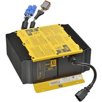
1625 - Battery charger CURTIS - Free user manual and instructions
Find the device manual for free 1625 CURTIS in PDF.


| Product Type | Battery Charger |
| Brand | Curtis |
| Model | 1625 |
| Compatible Battery Types | NiMH, NiCd, Li-Ion (AA/AAA) |
| Number of Charging Slots | 4 |
| Input Voltage | AC 100-240V, 50/60Hz |
| Output Voltage | 1.5V per battery (AA/AAA) |
| Charging Current | 200-500 mA (depending on battery type) |
| Charging Indicator | LED for each slot: red (charging), green (full) |
| Automatic Shut-off | Yes, when batteries are fully charged |
| Safety Features | Overcharge protection, short circuit protection, reverse polarity protection |
| Dimensions (L x W x H) | 100 x 70 x 25 mm |
| Weight | 150 g |
| Power Cord Length | 1.5 m |
| Housing Material | ABS plastic |
| Operating Temperature | 0°C to 40°C |
| Certification | CE, RoHS |
| Maintenance | Wipe with dry cloth; do not use liquids |
| Repairability | No user-serviceable parts; contact authorized service |
Frequently Asked Questions - 1625 CURTIS
User questions about 1625 CURTIS
0 question about this device. Answer the ones you know or ask your own.
Ask a new question about this device
Download the instructions for your Battery charger in PDF format for free! Find your manual 1625 - CURTIS and take your electronic device back in hand. On this page are published all the documents necessary for the use of your device. 1625 by CURTIS.
USER MANUAL 1625 CURTIS
Curtis Instruments, Inc.
200 Kisco Avenue
Mt. Kisco, NY 10549
www.curtisinstruments.com

Read Instructions Carefully!
Specifications are subject to change without notice.
© 2017 Curtis Instruments, Inc. ® Curtis is a registered trademark of Curtis Instruments, Inc.
© The design and appearance of the products depicted herein are the copyright of Curtis Instruments, Inc.
53099 Rev A 1/17
TABLE OF CONTENTS
1.0 Important Safety and Operating Instructions .... 1
Safe Operating Instructions ....2
2.0 Maintenance....3
3.0 Troubleshooting....4
4.0 Charging Profiles....5
Table 1 Troubleshooting Chart....4

1.0 IMPORTANT SAFETY AND OPERATING INSTRUCTIONS
This manual contains important safety and operating instructions for standard Curtis chargers. Please read this information in its entirety before using your Charger.

WARNING
Use charger only with an algorithm selected that is appropriate to the specific battery type. Other usage may cause personal injury and damage. Lead acid batteries may generate explosive hydrogen gas during normal operation. Keep sparks, flames, and smoking materials away from batteries. Provide adequate ventilation during charging. Never charge a frozen battery. Study all battery manufacturers' specific precautions (e.g. maximum charge rates and if cell caps should be removed while charging).

DANGER
Risk of electric shock. Connect charger power cord to an outlet that has been properly installed and grounded in accordance with all local codes and ordinances. A grounded outlet is required to reduce risk of electric shock – do not use ground adapters or modify plug. Do not touch uninsulated portions of output connector or uninsulated battery terminals. Disconnect the AC supply before making or breaking the connections to the battery. Do not open or disassemble charger. Do not operate this charger if the AC supply cord is damaged or if the charger has received a sharp blow, been dropped, or is damaged in any way – refer all repair work to the manufacturer, or qualified personnel. This charger is not intended for use by persons (including children) with reduced physical, sensory or mental capabilities, or lack of experience and knowledge on electrical systems and battery charging, unless they have been given supervision or instruction concerning use of the charger by a person responsible for their safety. Children should be supervised to ensure that they do not play with the charger.
Figure A
Model 1625
Battery Charger – Front view

SAFE OPERATING INSTRUCTIONS
- The charger may become hot during charging. Use hand protection to safely handle the charger during charging.
- Extension cords must be 3-wire cord no longer than 30m (100') at 10 AWG or 7.5m (25') at 16 AWG per UL guidelines.
- Only connect one 1625 Charger to a single 120VAC 15A circuit, or the circuit may become overloaded.
- The charger will conduct a self-test after being powered on, visible by flashing all of its LEDs in sequence.
Charger 10-LED Display
Ammeter
- If solid: Displays scale of output during bulk phase.
- If flashing: Output has been reduced due to high internal charger temperature. Displays charge profiles 1-6 for 11 seconds if no battery is connected.
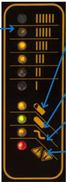
Bulk Charge Indicator
- If solid: Bulk charge phase complete (80% charged); in absorption phase.
- If flashing: Displays charge profile number if no battery is connected.
Charge Completion Indicator (Green Light)
- If solid: Charging complete and maintenance mode is active.
- If flashing: Absorption phase complete, in finishing phase.
AC Indicator
- If solid: AC voltage is above 185 volts.
- If flashing: AC voltage is between 105 volts and 185 volts.
- If off: AC voltage is below 105 volts.
Fault Indicator (Red Light)
- Charger error. Refer to troubleshooting information below.
Optional Charger Single-LED Display (internal or external)
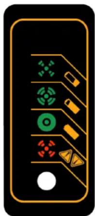
LED Color Indication
Green If solid: Charging complete and maintenance mode is active.
If flashing:
Short: <80% Charge.
Long: >80% Charge.
When battery is not connected: Charge Profile (Algorithm Number)
is displayed when first connected to AC, then will show “Battery low voltage” error.
Amber If flashing: Reduced power mode due to high internal charger temperature.
Red
If flashing: Charging error. Reset charger power and refer to Troubleshooting Instructions below.
2.0 MAINTENANCE INSTRUCTIONS
- Do not expose charger to high pressure water spray when cleaning vehicle.
- The enclosure of the charger meets IP66, making it dust-tight and protected against powerful water jets. The AC connection is rated to IP20, which is not protected against water. Protect the AC connection if used in wet or dusty environments.
-
If the detachable input power supply cord set is damaged, replace with a cord that is appropriate for your region:
-
This charger is provided with a cord set for connection to outlets operating at nominal 120 Volts (or 240 Volts as appropriate). If the input plug does not fit the power outlet, contact Curtis Instruments for the proper cord set terminating in an attachment plug of the proper configuration for the power outlet.
- 'North America: UL or CSA listed / approved detachable cord, 3 conductor, 16AWG minimum and rated SJT; terminated in a grounding type IEC 60320 C14 plug rated 250V, 13A minimum
- For all other regions: Safety approved detachable cord, 3 conductor, 1.5mm2 minimum, rated appropriately for industrial use. The cord set must be terminated on one end with a grounding type input connector appropriate for use in the country of destination and, on the other end, an output grounding type IEC 60320 C14 plug.
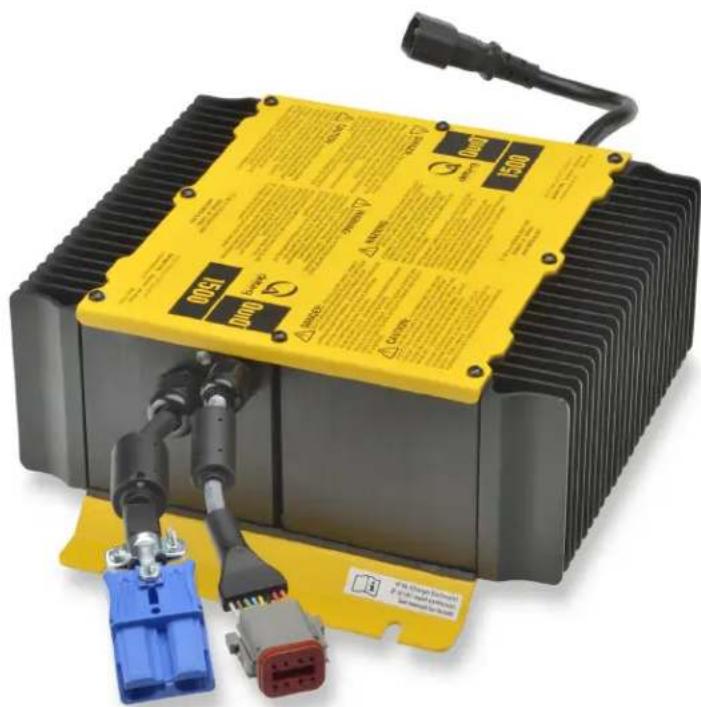
Figure B
Model 1625
Battery Charger – Rear view
3.0 TROUBLESHOOTING
If a fault occurs, count the number of red flashes between pauses and refer to the table below.
Table 1 Troubleshooting Chart
| Flashes Cause Solution | ||
 | Battery high voltage | Check battery size and condition. This fault will clear automatically once the condition has been corrected. |
 | Battery low voltage | Check battery size and condition. This fault will clear automatically once the condition has been corrected. |
 | Charge timeout caused by battery pack not reaching required voltage; or charger output reduced due to high temperatures. | Check connections, that battery type matches selected charge profile and operate the charger at a lower ambient temperature. Reset the charger by interrupting AC power for 15+ seconds. |
 | Battery could not be trickle charged up to minimum voltage. | Check for shorted or damaged cells. Reset the charger by interrupting AC power for 15+ seconds. |
 | Charger shutdown due to high internal temperature. | Ensure sufficient cooling airflow. Reset the charger by interrupting AC power for 15+ seconds. |
 | Internal charger fault | Reset the charger by interrupting AC power for 15+ seconds. Return to service depot if fault persists. |
NOTE: This is a Class A product complying with United States Federal Communications Commission, Code of Federal Regulations; 47CFR part 15. In a domestic environment this product may cause radio interference, in which case the user may be required to take adequate measures.
WARNING: Charger connectors must be mated to connectors from the same manufacturer. Failure to do so may void warranty and cause a hazardous condition or equipment damage.
4.0 SELECTING A CHARGE PROFILE
The 1625 Charger can store up to 10 charging profiles, also called charge algorithms. This section shows how to identify the default profile and select a new profile using the “tap method.”
Model 1625 chargers are also reprogrammable by using the dedicated programmer. Pre-2006 Model 1625 chargers with serial number prefix DQCP allow pre-loaded profiles to be selected but cannot be reprogrammed with new profiles.
Identify the default profile
-
Required supplies include an insulated wrench, eye protection and gloves.
-
Disconnect the AC power source from the charger, either from the wall outlet, or from the IEC320 connector on the charger (Figure 1).

Figure 1: Disconnect AC power.
- Use your insulated wrench to remove the positive lead from the positive terminal on the battery pack (Figure 2).

Figure 2: Remove positive lead from positive terminal on the battery pack.
- Reconnect AC power (Figure 3).
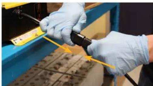
Figure 3: Reconnect AC power to the charger.
- Charger will conduct a self-test of its LED indicators (Figure 4).
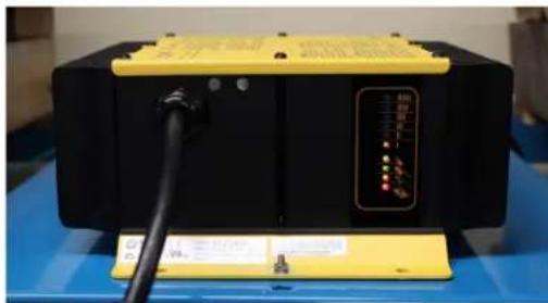
Figure 4: Charger LED indicator self-test.
6a. For 11 seconds after the self-test, the charger will display its default charge profile. Profiles #1-6 will display on the ammeter, as well as on the bulk charge indicator (Figure 5).

Figure 5: Charge profile #1 on the ammeter.
6b. Charge profiles #7 and above will display on the bulk charge indicator. If the charge profile number has two digits, it will be displayed by one or more flashes, a pause, then one or more flashes (e.g. #13 = Ⓞ ⚡️) (Figure 6).
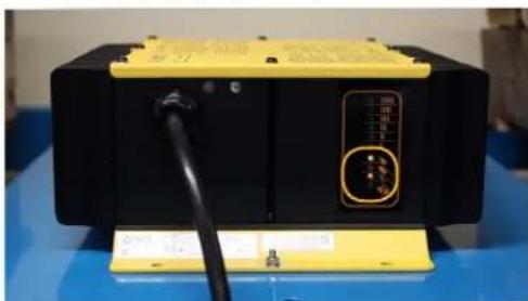
Figure 6: Bulk charge indicator displays charge profiles 7 and above.
SELECTING A CHARGE PROFILE CONT'D
Select a new profile
-
Disconnect AC power (Figure 1).
-
Reconnect AC power (Figure 3).
-
Touch the positive lead to the positive terminal for three seconds (+/- 0.5 seconds), then remove the lead. You will see the next profile displayed on the charger's display. Repeat this step until you reach the desired charge profile (Figure 7).
-
When the charger displays the desired charge profile, apply the positive lead to the positive battery terminal for 10 seconds. When the charge profile is locked, you will hear a click from the charger. See Figure 7 for how to apply the positive lead to the positive terminal.
-
Disconnect AC power, wait for the LED indicator display to turn off, then reconnect AC power. (Figure 3)
-
Check the LED display to ensure that the desired charge profile is selected.
-
Disconnect the charger from AC power and wait for the LED indicator display to turn off. (Figure 1)
-
Reconnect the positive lead to the positive battery terminal (Figure 8).

Figure 7: Touch the positive lead to the positive battery terminal for 3 seconds.

Figure 8: Reattach the positive lead to the positive terminal after disconnecting AC power.


- TABLE OF CONTENTS
- 1.0 IMPORTANT SAFETY AND OPERATING INSTRUCTIONS
- WARNING
- DANGER
- SAFE OPERATING INSTRUCTIONS
- CHARGER 10-LED DISPLAY
- AMMETER
- BULK CHARGE INDICATOR
- CHARGE COMPLETION INDICATOR (GREEN LIGHT)
- AC INDICATOR
- FAULT INDICATOR (RED LIGHT)
- OPTIONAL CHARGER SINGLE-LED DISPLAY (INTERNAL OR EXTERNAL)
- LED COLOR INDICATION
- 2.0 MAINTENANCE INSTRUCTIONS
- 3.0 TROUBLESHOOTING
- 4.0 SELECTING A CHARGE PROFILE
- IDENTIFY THE DEFAULT PROFILE
- SELECTING A CHARGE PROFILE CONT'D
- SELECT A NEW PROFILE
Brand : CURTIS
Model : 1625
Category : Battery charger