
24CR671N-2P - Desktop computer LG - Free user manual and instructions
Find the device manual for free 24CR671N-2P LG in PDF.
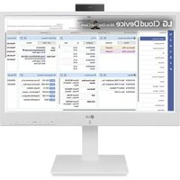


| Product Type | All-in-One Desktop Computer |
| Model Number | 24CR671N-2P |
| Display Size | 24 inches (diagonal) |
| Dimensions (W x H x D) | Approx. 540 x 400 x 200 mm |
| Weight | Approx. 5.0 kg |
| Power Supply | AC 100-240V, 50/60Hz, 19V DC output |
| Power Consumption (Max) | 65 W |
| Operating System | Windows 11 (pre-installed) |
| Processor | Intel Core i5 (12th gen or similar) |
| Memory (RAM) | 8 GB DDR4 |
| Storage | 256 GB SSD |
| Graphics | Integrated Intel UHD Graphics |
| Connectivity | Wi-Fi 6, Bluetooth 5.0, USB 3.0, HDMI |
| Main Functions | Home computing, web browsing, office applications, multimedia playback |
| Maintenance | Clean exterior with a soft dry cloth; avoid liquid contact; ensure proper ventilation |
| Safety Precautions | Use only provided power adapter; do not block air vents; keep away from water |
| Spare Parts & Repairability | Contact LG authorized service center for replacement parts; user-replaceable RAM and storage |
| General Information | Manufacturer: LG; Model year: 2023; Country of origin: China |
Frequently Asked Questions - 24CR671N-2P LG
User questions about 24CR671N-2P LG
0 question about this device. Answer the ones you know or ask your own.
Ask a new question about this device
Download the instructions for your Desktop computer in PDF format for free! Find your manual 24CR671N-2P - LG and take your electronic device back in hand. On this page are published all the documents necessary for the use of your device. 24CR671N-2P by LG.
USER MANUAL 24CR671N-2P LG
LG Cloud Device SERVICE MANUAL
CHASSIS : LM22G
MODEL : 24CR670N-6N/ 24CR670N6P 24CR670NK6N/24CR670NK6P 24CR671N-2P/ 24CR671N-6P 24CR671NK6P
CAUTION BEFORE SERVICING THE CHASSIS, READ THE SAFETY PRECAUTIONS IN THIS MANUAL.

P/NO : MFL71804641 (2311-REV01)
Any reproduction, duplication, distribution (including by way of email, facsimile or other electronic means), publication, modification, copying or transmission of this Service Manual is STRICTLY PROHIBITED unless you have obtained the prior written consent of the LG Electronics entity from which you received this Service Manual. The material covered by this prohibition includes, without limitation, any text, graphics or logos in this Service Manual.
CONTENTS
CONTENTS 2
SAFETY PRECAUTIONS .... 3
SPECIFICATION 4
BLOCK DIAGRAM 7
EXPLODED VIEW 8
TROUBLE SHOOTING GUIDE ...... 9
DISASSEMBLE GUIDE ...... APPENDIX
SOFTWARE UPDATE GUIDE ...... APPENDIX
SAFETY PRECAUTIONS
IMPORTANT SAFETY NOTICE
Many electrical and mechanical parts in this chassis have special safety-related characteristics. These parts are identified by ⚠ in the Exploded View.
It is essential that these special safety parts should be replaced with the same components as recommended in this manual to prevent Shock, Fire, or other Hazards.
Do not modify the original design without permission of manufacturer.
General Guidance
An isolation Transformer should always be used during the servicing of a receiver whose chassis is not isolated from the AC power line. Use a transformer of adequate power rating as this protects the technician from accidents resulting in personal injury from electrical shocks.
It will also protect the receiver and its components from being damaged by accidental shorts of the circuitry that may be inadvertently introduced during the service operation.
If any fuse (or Fusible Resistor) in this TV receiver is blown, replace it with the specified.
When replacing a high wattage resistor (Oxide Metal Film Resistor, over 1 W), keep the resistor 10 mm away from PCB.
Keep wires away from high voltage or high temperature parts.
Before returning the receiver to the customer,
always perform an AC leakage current check on the exposed metallic parts of the cabinet, such as antennas, terminals, etc., to be sure the set is safe to operate without damage of electrical shock.
Leakage Current Cold Check (Antenna Cold Check)
With the instrument AC plug removed from AC source, connect an electrical jumper across the two AC plug prongs. Place the AC switch in the on position, connect one lead of ohm-meter to the AC plug prongs tied together and touch other ohm-meter lead in turn to each exposed metallic parts such as antenna terminals, phone jacks, etc.
If the exposed metallic part has a return path to the chassis, the measured resistance should be between 1 MΩ and 5.2 MΩ.
When the exposed metal has no return path to the chassis, the reading must be infinite.
Another abnormality exists that must be corrected before the receiver is returned to the customer.
Leakage Current Hot Check (See Figure below)
Plug the AC cord directly into the AC outlet.
Do not use a line isolation transformer during this check.
Connect a 1.5 kΩ / 10 W resistor in parallel with a 0.15 μF capacitor between a known good earth ground (water pipe, conduit, etc.) and the exposed metallic parts.
Measure the AC voltage across the resistor using an AC voltmeter with 1000 ohms/volt or more sensitivity.
Reverse the plug of the AC cord into the AC outlet and repeat AC voltage measurements for each exposed metallic part. Any voltage measured must not exceed 0.75 V RMS, which corresponds to 0.5 mA.
In case any measurement is out of the limits specified, there is a possibility of shock hazard, and the set must be checked and repaired before it is returned to the customer.
Leakage Current Hot Check circuit
When 25 A is impressed between Earth and 2nd Ground for 1 second, resistance must be less than 0.1 Ω.
*Based on adjustment standard
SPECIFICATIONS
NOTE: Specifications and other information are subject to change without notice for improvement.
- General Specification
| Item Content Remark | |||||
| 1 | Customer BRAND LGE Product | ||||
| 2 | User Model Name 24CR67* | ||||
| 3 | Sale region Worldwide | ||||
| 4 | Feature 24"wide LCD Monitor with RFID Module, Webcam | ||||
| 5 | Chassis Name LM22G PCB, Product spec., Adjust- | ment spec. | |||
| 6 | GeneralScope | External SW & Adj. | Tact Key (Menu, Left, Right, OK/Input ,Down, Up Power) 7 Tack Key | ||
| Function OSD, | DDC2B, DDC2AB, HDCP, Control Lock, Wide/Original, Smart Energy Saving, Color Weakness, Black level, Reader mode, Flicker safe | ||||
| 7 | Input HDMI IN 1ea | ||||
| DP OUT 1ea | |||||
| USB-C | 1ea | ||||
| USB 2.0 2ea | |||||
| USB 3.1 4ea | |||||
| MIC/Audio Combo | 1ea | ||||
| Ethernet 1ea(RJ45) | |||||
| SFP(Fiber) | 1ea(Fiber Connection) | ||||
| WiFi+BT 1ea | |||||
| SOUND | 1ea(3W Speaker x 2ea) | ||||
| 8 | Power Cord | Length | 1.5m ± 0.05m: | ||
| Weight | 0.20kg ± 10%, | ||||
| Color | BLACK | ||||
| 9 | Power | Adapter | Input: 100-240 V ~ 50/60 Hz 1.5 A | ||
| Output: 19V, 6.32A | |||||
| 10 | Power Rating | Input: AC100~240V 50/60Hz, Output: 19V 6.32A | |||
- Engineering Specification
| No. | Item | Spec | Remarks | ||
| 1 | Operating Frequency | HDMI | Horizontal | 30 - 85kHz | |
| Vertical | 56 - 75 Hz | ||||
| 2 | Resolution | HDMI | Max. | 1920x1080 @ 75Hz | |
| Recommend | 1920x1080 @ 60Hz | ||||
| 3 | Power Input Voltage | Voltage: AC 100 ~ 240Vac, 50-60Hz, 1.8A-0.7A | |||
3. Signal Timing (Resolution)
3.1. Signal (Video & Sync)
- H/V Timing : HDMI
| No. | Section Pol. | Dot Clock | [MHz] | Frequen-cy[kHz]/[Hz] | Total Cycle(E) | Dis-play(A) | FrontPorch(D) | Sync.(C) | BackPorch(B) | Resolution Remark | |
| 1 | H(Pixels) - 25.175 | 31 | 469 800 640 | 16 96 48 640 | x 480 | ||||||
| V(Lines) | - | 59.94 | 525 | 480 | 10 | 2 | 33 | ||||
| 2 | H(Pixels) | - | 31.5 | 37.5 | 840 | 640 | 16 | 64 | 120 | 640 x 480 | |
| V(Lines) | - | 75 | 500 | 480 | 1 | 3 | 16 | ||||
| 3 | H(Pixels) | - | 28.321 | 31.468 | 900 | 720 | 18 | 108 | 54 | 720 x 400 | |
| V(Lines) | + | 70.08 | 449 | 400 | 12 | 2 | 35 | ||||
| 4 | H(Pixels) | + | 27 | 31.47 | 848 | 720 | 16 | 62 | 50 | 720 x 480 | |
| V(Lines) | + | 59.94 | 528 | 480 | 9 | 9 | 30 | ||||
| 5 | H(Pixels) | + | 40 | 37.879 | 1056 | 800 | 40 | 128 | 88 | 800 x 600 | |
| V(Lines) | + | 60.317 | 628 | 600 | 1 | 4 | 23 | ||||
| 6 | H(Pixels) | + | 49.5 | 46.875 | 1056 | 800 | 16 | 80 | 160 | 800 x 600 | |
| V(Lines) | + | 75 | 625 | 600 | 1 | 3 | 21 | ||||
| 7 | H(Pixels) | - | 65 | 48.363 | 1344 | 1024 | 24 | 136 | 160 | 1024 x 768 | |
| V(Lines) | - | 60 | 806 | 768 | 3 | 6 | 29 | ||||
| 8 | H(Pixels) | + | 78.75 | 60.023 | 1312 | 1024 | 16 | 96 | 176 | 1024 x 768 | |
| V(Lines) | + | 75.029 | 800 | 768 | 1 | 3 | 28 | ||||
| 9 | H(Pixels) | + | 108 | 67.5 | 1600 | 1152 | 64 | 128 | 256 | 1152 x 864 | |
| V(Lines) | + | 75 | 900 | 864 | 1 | 3 | 32 | ||||
| 10 | H(Pixels) | + | 74.25 | 45 | 1650 | 1280 | 110 | 40 | 220 | 1280 x 720 | |
| V(Lines) | + | 60 | 750 | 720 | 5 | 5 | 20 | ||||
| 11 | H(Pixels) | - | 83.5 | 49.702 | 1680 | 1280 | 72 | 128 | 200 | 1280 x 800 | |
| V(Lines) | + | 60 | 831 | 800 | 3 | 6 | 22 | ||||
| 12 | H(Pixels) | + | 108 | 63.981 | 1688 | 1280 | 48 | 112 | 248 | 1280 x 1024 | |
| V(Lines) | + | 60.023 | 1066 | 1024 | 1 | 3 | 38 | ||||
| 13 | H(Pixels) | + | 135 | 79.976 | 1688 | 1280 | 16 | 144 | 248 | 1280 x 1024 | |
| V(Lines) | + | 75.035 | 1066 | 1024 | 1 | 3 | 38 | ||||
| 14 | H(Pixels) | - | 121.75 | 65.317 | 1864 | 1400 | 88 | 144 | 232 | 1400 x 1050 | |
| V(Lines) | + | 59.978 | 1089 | 1050 | 3 | 4 | 32 | ||||
| 15 | H(Pixels) | - | 106.5 | 55.935 | 1904 | 1440 | 80 | 152 | 232 | 1440 x 900 | |
| V(Lines) | + | 59.887 | 934 | 900 | 3 | 6 | 25 | ||||
| 16 | H(Pixels) | + | 108 | 60 | 1800 | 1600 | 24 | 80 | 96 | 1600 x 900 | |
| V(Lines) | + | 60 | 1000 | 900 | 1 | 3 | 96 | ||||
| 17 | H(Pixels) | - | 146.25 | 65.29 | 2240 | 1680 | 104 | 176 | 280 | 1680 x 1050 | |
| V(Lines) | + | 59.954 | 1089 | 1050 | 3 | 6 | 30 | ||||
| 18 | H(Pixels) | + | 148.5 | 67.5 | 2200 | 1920 | 88 | 44 | 148 | 1920 x 1080 | |
| V(Lines) | + | 60 | 1125 | 1080 | 4 | 5 | 36 | ||||
| 19 | H(Pixels) | + | 174.5 | 83.89 | 2080 | 1920 | 48 | 32 | 80 | 1920 x 1080 | |
| V(Lines) | + | 74.97 | 1119 | 1080 | 3 | 5 | 31 | ||||
3.2. Video input: HDMI
| Factory support mode (Preset Mode) | Horizontal frequency (KHz) | Vertical frequency (Hz) | HDMI | |
| 1 480P | 31.5 60 O | |||
| 2 576P | 31.25 50 O | |||
| 3 720P | 37.5 50 O | |||
| 4 720P | 45 60 O | |||
| 5 1080P | 56.25 50 O | |||
| 6 1080P | 67.5 60 O | (Recommend Mode) |
BLOCK DIAGRAM
![```mermaid graph TD A["Hardware Module"] --> B["CPU"] B --> C["PC"] C --> D["Micro-In"] D --> E["IC"] E --> F["Micro-In"] F --> G["IC"] G --> H["Micro-In"] H --> I["Micro-In"] I --> J["Micro-In"] J --> K["Micro-In"] K --> L["Micro-In"] L --> M["Micro-In"] M --> N["Micro-In"] N --> O["Micro-In"] O --…](/content/2026/07/1481346/images/d1e8ed0ef9749757801319f86564a70ff9ea2bbf3bad58cbc174cae4e9bb96e6.jpg)
EXPLODED VIEW
IMPORTANT SAFETY NOTICE
Many electrical and mechanical parts in this chassis have special safety-related characteristics. These parts are identified by in the EXPLODED VIEW.
It is essential that these special safety parts should be replaced with the same components as recommended in this manual to prevent Shock, Fire, or other Hazards.
Do not modify the original design without permission of manufacturer.

TROUBLE SHOOTING GUIDE
First of all, Check whether there is SVC Bulletin in GSCS System for these model.
1. No Power On
Cold-Boot Power Sequence
![graph TD A["Adapter"] --> B["VDC_IN"] B -->|NO.1| C["VPOWERRAIL"] C -->|NO.2| D["V3A_EC (Vin=VPOWERRAIL)"] D -->|NO.3| E["A_PWR_ON"] E -->|NO.4| F["V3A (Vin=VPOWERRAIL)"] E -->|NO.5| G["V5A (Vin=VPOWERRAIL)"] F -->|NO.6| H["DSW_PWROK"] H -->|NO.7| I["SLP_SUS#"] I --> J["V1.8A (Vin=V3A)"] J -->|NO.8|…](/content/2026/07/1481346/images/7d36d7226bcad03507aa4c5bbb758f9664def3454d8d527a79aa0e12fda7586f.jpg)
![graph TD A["Forced shutdown less than 15sec power button press.<br>Press power button again if not automatically power on"] --> B["No Power on?"] B --> C["Check VPOWERRAIL voltage level (19V)?"] C -->|N| D["Check power connector"] D --> E["Replace power connector or adapter"] C -->|Y| F["Check EC_SY…](/content/2026/07/1481346/images/118c227caaabcb492e9d7abd3d2223e7cf29385a5afbeb92083b4e9dd4f723e3.jpg)
- No Screen On

3. No Video - HDMI
![graph TD A["check input signal format is it supported?"] -->|Y| B["Check HDMI cable for damage or open connection"] B -->|Y| C["check JK100 for proper connection or damage"] C -->|N| D["Replace connector"] C -->|Y| E["Check I2C signal (JK100)"] E -->|N| F["Re download EDID data"] E -->|Y| G["Replace…](/content/2026/07/1481346/images/f9f7ace021f85d0a134cfb2c2ae3a05efe52353cab1b2a0a623b4fc85c262255.jpg)
DISASSEMBLE GUIDE
Disassemble
- Stand


- Back Cover


- Cable 4. Side USB


Disassemble
5. Webcam


6. Speaker

7. Rear Shield

8. Control

9. Module

Disassemble
- W-LAN, Memory, SSD, Main Board

SOFTWARE UPDATE
SOFTWARE UPDATE
- Subject: SW Upgrade Guide
- Applied Model: xxCQ650 / xxCR650 / xxCR670
- Check the BIOS Version
- Press the Power button and press the [F2] Key to enter the "Setup Menu" - Choose the "Main > System Information", it will show the below screen.
- Check the BIOS Version

- How to upgrade the BIOS:
1) Run the "w.bat" file of shared BIOS flash files.
When run it, it will show the below-right screen, and then the set reboots automatically.


2) It will progress to upgrade the BIOS such as below screen, and then the set will reboot automatically.

Copyright © 2023 LG Electronics Inc. All rights reserved. Only training and service purposes.
SOFTWARE UPDATE
5. DMI String Update
- Use the same tool for updating the BIOS to update the DMI String. - Run the CMD as administrator in the folder of the BIOS Flash File.
Serial Number Update
- If you want to insert the Serial Number such as "1234567890", please refer to the below to update it. - In the CMD dialog, run [WinFlash64.exe /patch /dss "1234567890"]
Product Name Update
- If you want to insert the Product name such as "CQ600", please refer to the below to update it. - In the CMD dialog, run [WinFlash64.exe /patch /dps "CQ600"]
UUID Number Update
- If you want to insert the UUID, please refer to the below to update it. (UUID will be produced randomly.) - In the CMD dialog, run [WinFlash64.exe /patch /dus]
Serial Number / Product Name / UUID Number Update (at the same time)
- If you want to insert all items at the same time, please refer to the below to update it. - In the CMD dialog, run [WinFlash64.exe /patch /dus /dps "CQ600" /dss "1234567890"]
![Administrator: Windows PowerShell - WinFlash64.exe /patch /dus/dps "CQ600" /dss "1234567890" PS C:\Users\Admin\Desktop\J1TG0220> cnd Microsoft Windows [Version 10.0.19044.1288] (c) Microsoft Corporation. All rights reserved. C:\Users\Admin\Desktop\J1TG0220>WinFlash64.exe /patch /dus /dps "CQ600" /ds…](/content/2026/07/1481346/images/8271868ecc4527adbb74efbc8d4e4540738bc82dd48efd8063087cd8a31fb6bb.jpg)
6. How to check the DMI Information
- Press the Power button
and press the [F2] Key to enter the "Setup Menu"
- Choose "main > System Information", it will show the screen below. - Check the changed DMI information.

SOFTWARE UPDATE
7. How to install the Windows image
STEP 1: Prepare a WinPE bootable USB and copy the Windows OS image to the USB. STEP 2: Apply the OS image.
1) Turn on the thin client and enter the boot device selection by pressing F10. 2) Boot from the bootable USB.

3) Go to the image directory and run the image write script file (e.g., cd CQ6_LG_IMAGE\24CQ650_19044IE_EN08\24CQ650_19044IE_EN08.bat)

SOFTWARE UPDATE
4) After installing the image, eject the boot USB first, and exit the console.
![Microsoft Windows [Version 10.0.16281.1000] LG Image install script # Image ID : 24CQ650_19044IE_EN00 Start time : Thu 03/03/2022 0:27:45.04 *************** Fixed Hard Disk Information Index InterfaceType Size Status 0 SCSI 128834708480 OK This system has only one fixed hard disk. System disk to app…](/content/2026/07/1481346/images/3e1351e067f1e80a0de78bac2fe4f5404027c982728f2cfa795389e8a0bec8dc.jpg)

SOFTWARE UPDATE
5) The thin client will restart 2~3 times automatically (under 10 minutes) due to system configuration.


SOFTWARE UPDATE
8. How to check the windows image version
Execute LG Cloud Panel App on "Admin" account.
If you are "User" account, execute LG Cloud Panel App run as administrator (Password is "Admin")


SOFTWARE UPDATE
9. Firmware Version Check
-After power On, Change to HDMI Mode on the Input Menu -DC power off(by Power button) -Press the Power button and Menu Key at the same time during 3 sec -After Screen On, press the Menu Key to shows the OSD button

- How to update the firmware:
1) Preparation the F/W : - 24CQ650_Realtek_RTD2536WEC_V310_0408 A0FE_Rev5155_220223.bin 2) Connect the Cable
![graph LR A["PC or Notebook"] -->|USB Cable| B["Monitor JIG"] B -->|HDMI Cable| C["Monitor"]](/content/2026/07/1481346/images/294f99f381b0ec7ba05f446d2b0afff5c4d6d77c892e79a9084704abee908465.jpg)
3) Update F/W
- Method: Refer the attached file
Realtek ISP Guide
4) After update the F/W, It will do the Factory Reset

Connect the HDMI cable between HDMI port of Jig and HDMI port of monitor Connect the USB cable Between USB-B port of Jig And USB-A port of PC

LG
Life's Good

- LG CLOUD DEVICE SERVICE MANUAL
- CONTENTS
- SAFETY PRECAUTIONS
- IMPORTANT SAFETY NOTICE
- GENERAL GUIDANCE
- BEFORE RETURNING THE RECEIVER TO THE CUSTOMER
- LEAKAGE CURRENT COLD CHECK (ANTENNA COLD CHECK)
- DO NOT USE A LINE ISOLATION TRANSFORMER DURING THIS CHECK
- SPECIFICATIONS
- SIGNAL TIMING (RESOLUTION)
- SIGNAL (VIDEO & SYNC)
- BLOCK DIAGRAM
- EXPLODED VIEW
- TROUBLE SHOOTING GUIDE
- NO POWER ON
- COLD-BOOT POWER SEQUENCE
- NO VIDEO - HDMI
- DISASSEMBLE GUIDE
- DISASSEMBLE
- WEBCAM
- SPEAKER
- REAR SHIELD
- CONTROL
- MODULE
- SOFTWARE UPDATE
- DMI STRING UPDATE
- HOW TO CHECK THE DMI INFORMATION
- HOW TO INSTALL THE WINDOWS IMAGE
- HOW TO CHECK THE WINDOWS IMAGE VERSION
- FIRMWARE VERSION CHECK
Brand : LG
Model : 24CR671N-2P
Category : Desktop computer