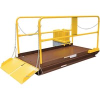
WL-100-6-710 - Plateforme élévatrice industrielle Vestil - Free user manual and instructions
Find the device manual for free WL-100-6-710 Vestil in PDF.


| Product Type | Hydraulic Lift Table |
| Brand | Vestil |
| Model | WL-100-6-710 |
| Load Capacity | 1000 lbs (454 kg) |
| Platform Size (L x W) | 48 in x 30 in (1219 mm x 762 mm) |
| Minimum Platform Height | 6 in (152 mm) |
| Maximum Platform Height | 30 in (762 mm) |
| Lifting Mechanism | Hydraulic foot pump |
| Power Source | Manual (hydraulic) |
| Net Weight | 250 lbs (113 kg) |
| Material | Steel with powder coat finish |
| Color | Yellow / Black |
| Shipped Weight | 270 lbs (122 kg) |
| Shipping Dimensions (L x W x H) | 52 in x 32 in x 12 in (1321 mm x 813 mm x 305 mm) |
| Included Components | Foot pedal, handle, safety prop |
| Maintenance | Regular lubrication of pivot points and hydraulic cylinder |
| Safety Features | Safety prop, overload protection valve |
| Standards Compliance | ANSI/ASME safety standards |
| Warranty | 1 year limited warranty |
Frequently Asked Questions - WL-100-6-710 Vestil
User questions about WL-100-6-710 Vestil
0 question about this device. Answer the ones you know or ask your own.
Ask a new question about this device
Download the instructions for your Plateforme élévatrice industrielle in PDF format for free! Find your manual WL-100-6-710 - Vestil and take your electronic device back in hand. On this page are published all the documents necessary for the use of your device. WL-100-6-710 by Vestil.
USER MANUAL WL-100-6-710 Vestil
Vestil Manufacturing Corp.
A company dedicated to solving loading dock and material handling problems since 1955.
2999 North Wayne Street, P.O. Box 507, Angola, IN 46703
Telephone: (260) 665-7586 -or- Toll Free: (800) 348-0868
Fax: (260) 665-1339
http://www.vestil.com/ email: info@vestil.com
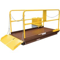
WL-100 Series Premium Truck Scissor Dock Lift
Instruction Manual

Model WL-100-5-68
Receiving instructions:
After delivery, remove the Premium Truck Scissor Dock Lift ("Lift") from its shipping pallet. Inspect the Lift to determine whether it sustained damage during transport. If damage is discovered, record a complete description of it o the bill of lading and file a claim with the carrier immediately! If the product is undamaged, discard the packaging.
NOTE:
The end user is solely responsible for confirming that product design, use, and maintenance comply with laws, regulations, codes, and mandatory standards applied where the Lift is used.
Replacement Parts and Technical Assistance:
If you have questions that are not addressed in these instructions, or to order replacement parts, labels, and accessories, call (260) 665-7586 and ask for the Service and Parts Department. You can also reach Service and Parts online at http://www.vestilmfg.com/parts_info.htm.
Electronic Copies of Instruction Manuals:
Additional copies of this instruction manual may be downloaded from https://www.vestil.com/page-manuals.php.
Table of Contents
This manual uses SIGNAL WORDS to direct the reader's attention to important safety-related messages. These messages describe uses of the product that could result in personal injury or property damage. Each signal word corresponds to a specific hazard level. The following are definitions of signal words that might appear in this manual.

Identifies a hazardous situation which, if not avoided, WILL result in DEATH or SERIOUS INJURY. Use of this signal word is limited to the most extreme situations.

Identifies a hazardous situation which, if not avoided, COULD result in DEATH or SERIOUS INJURY.

Indicates a hazardous situation which, if not avoided, COULD result in MINOR or MODERATE injury.

Identifies practices likely to result in product/property damage, such as operation that might damage the product.
HAZARDS
Vestil Manufacturing strives to identify all foreseeable hazards associated with the use of its products. However, material handling is dangerous and no manual can address every risk. The end user is ultimately responsible for exercising sound judgment at all times in the use of this product.
Improper or careless operation of this Lift might result in serious personal injuries.
- Read and understand this entire manual before installing, assembling, using or servicing this Premium Scissor Dock Lift ("Lift"). Keep this manual in a location known to persons who use the Lift. Read the manual whenever necessary to refresh your understanding of proper use, inspection, and maintenance procedures. Failure to read and understand this owner's manual before using or servicing the Lift constitutes a misuse of the product.
- The Lift presents pinch point and hydraulic pressure hazards to the user and bystanders. ALWAYS follow these instructions to avoid injury.
- The Lift is intended for use on a level concrete surface. DO NOT use a Lift that has not been anchored to a level concrete surface. See installation instructions starting on page 17.
- The Lift shall be installed only by trained and qualified personnel with access to appropriate equipment. Electrical connections shall be performed by a qualified electrician.
-
DO NOT load the Lift beyond its lift rated capacity. Handle only stable and safely arranged loads within the maximum capacity of the Lift. The lift capacity is printed on the nameplate on the hinged end of the platform.
-
ALWAYS use care to center and distribute loads evenly on the platform.
- DO NOT attempt to lift an overhanging or cantilever load.
- ALWAYS engage parking brakes or wheel locks on equipment before operating the Lift.
- DO watch the load for shifting when the Lift is in operation.
- ALWAYS keep clear of the Lift while it is moving.
- DO NOT place hands or feet under the platform. DO NOT put any body part in the scissor mechanism.
- DO NOT store objects under the platform.
• DO NOT use the Lift if any damage is observed, or unusual noises heard. - DO NOT operate a Lift with its perimeter toe guard removed, disabled, or inoperable.
- ALWAYS place the safety chains across the both ends of the platform before operating the Lift. ALWAYS keep the chains in place if a falling hazard exists.
- ALWAYS raise both bridge segments before operating the Lift.
- DO NOT board an elevated platform from the ground. DO NOT step from an elevated platform to ground level.
- Do not exceed a travel rate of two feet per second when moving across the platform.
- DO ensure that all information, safety, and warning labels remain in place and are legible. See the Labeling diagram on p. 29.
- ALWAYS remove any load from the platform before servicing the Lift or its hydraulic power unit. DO completely lower the platform, or use the attached maintenance prop bars to support the platform, before servicing this product.
- If additional oil is needed, DO use anti-wear hydraulic oil with a viscosity grade of 150 SUS at 100°F (ISO 32 cSt @ 40°C) or Dexron non-synthetic transmission fluid. DO NOT use brake fluid or jack oils in the hydraulic system.
- Maintenance and repairs are to be done only by personnel qualified to perform the required work. Consideration will not be given for warranty repair charges without prior written authorization by the manufacturer.
- DO NOT perform any modifications to the lift table without the manufacturer's written approval. Failure to receive authorization for changes to the equipment automatically voids the warranty, and may make the Lift unsafe for use.
NOTICE
Proper use and maintenance are essential for this product to function properly.
• Always use this product in accordance with the instructions in this manual.
- Periodically lubricate pivot points with bearing grease.
- Use only factory-approved replacement parts. Contact Vestil Manufacturing to order replacement or spare parts.
- Contact the manufacturer for SDS (Safety Data Sheet) information.
MODEL NUMBER AND CAPACITY
The Scissor Dock Lift model number, serial number and capacities are printed on the nameplate, found on the hinge end of the platform. Refer to the product catalog of the factory for further information. Include the model and serial numbers in all correspondence with your dealer or the factory.
The load capacity rating as printed on the nameplate of your Lift designates its net capacity. The addition of ancillary equipment to the Lift will necessitate a lowering of the load capacity. The Lift's load capacity must never be exceeded, as permanent damage or personal injury may result.
Space intentionally blank.
EXPLODED ASSEMBLY VIEWS

| ITEM | DESCRIPTION |
| 1 | BASE ASSEMBLY |
| 2 | LEGSET ASSEMBLY * |
| 3 | PERIMETER TOE GUARD ASSEMBLY (under platform) * |
| 4 | PLATFORM AND SAFETY RAILS * |
| 5 | POWER UNIT * |
* See separate illustrations and tables for service parts lists

WL-100 Legset Service Components
| ITEM | PART NUMBER | DESCRIPTION | QTY |
| 1 | 99-021-925 | CYLINDER, HYDRAULIC, 3\ 1/4" × 19", RAM STYLE | 2-4 |
| 2 | 05-612-300 | WELDMENT, ROLLER PIN ASSEMBLY | 4 |
| 3 | 05-527-300 | ROLLER, ASSEMBLY | 4 |
| 4 | 05-112-302 | CYLINDER PIN (ALL 2- AND 3-CYLINDER MODELS) | 2 |
| 01-112-015 | CYLINDER PIN (3-CYLINDER MODELS, CENTER PIN ONLY) | 1 | |
| 05-115-306 | CYLINDER PIN (ALL 4-CYLINDER MODELS) | 4 | |
| 5 | 01-145-006 | SHAFT COLLAR, SPLIT, 1\ 1/8" (4-CYLINDER MODELS, 6' AND 7' WD) | 2 |
| 6 | 05-112-301 | PIN, AXLE | 2 |
| 7 | 01-111-017 | BUSHING, POLYGON, 2" ID x 2 3/4" LG | 2 |
| 8 | 99-115-001 | WASHER, THRUST | 2 |
| 9 | 05-112-002-001 | PIN, HINGE | 2 |
| 10 | 01-111-022 | BUSHING, POLYGON, 1\ 1/8" ID x 1 1/4" LG | 4 |
| 11 | 32415 | 5/16 - 18 × 1/2 HWH THREAD CUTTING SCREW, TYPE F, ZINC | 4 |
| 12 | 64113 | SPRING PIN, PLAIN FINISH, 3/16" X 1" | 6 |
| 13 | 26335 | 3/8" × 2 SHOULDER BOLT | 2 |
| 14 | 33006 | 5/16" USS FLAT WASHER | 2 |
| 15 | 37021 | 5/16-18 NYLOCK NUT | 2 |
| 16 | 5546062 | GREASE ZERK, 3/16", STRAIGHT, DRIVE-IN | 6 |
PERIMETER TOE GUARD ASSEMBLY

WL-100 Perimeter Toe Guard Assembly Service Components
| ITEM | PART NUMBER | DESCRIPTION | QTY. |
| 1 & 2 | 01-015-305 | TOE GUARD EXTRUSION FOR 6 FT SIDES | 2 + 2 |
| 01-015-306 | TOE GUARD EXTRUSION FOR 7 FT SIDES | ||
| 01-015-301 | TOE GUARD EXTRUSION FOR 8 FT SIDES | ||
| 01-015-302 | TOE GUARD EXTRUSION FOR 10 FT SIDES | ||
| 01-015-303 | TOE GUARD EXTRUSION FOR 12 FT SIDESCONSULT FACTORY FOR OTHER LENGTHS | ||
| 3 | 01-015-009 | TOE GUARD SUPPORT, CAST RUBBER HOUSING | 4 |
| 4 | 01-015-017 | TOE GUARD, LIMIT SWITCH ACTUATOR | 4 |
| 5 | 01-145-010 | SPECIALTY HARDWARE, TOE GUARD BOLT | 4 |
| 6 | 24189 | #8-32 FHSCS | 4 |
| 7* | 01-022-022 | SWITCH, LIMIT (N. C. MICRO) | 4 |
| 8* | 24008 | 4-40 X 1/2 BHCS | 8 |
| 9 | 11015 | HEX BOLT, GRADE A, ZINC PLATED, 1/4"-20 X 3" | 4 |
| 10 | 37018 | NYLON LOCK NUT,GRADE 2, ZINC FINISH,1/4"-20 | 5 |
| 11 | 33004 | FLAT WASHER, USS, ZINC PLATED, ∅1/4" | 8 |
| 12^† | 01-022-001 | LIMIT SWITCH W/ROLLER ARM | 1 |
| 13^† | 22805 | ELEVATOR BOLT, LIMIT SWITCH | 1 |
* Item attaches to platform.
† Item attaches to base.
PLATFORM AND SAFETY RAILS
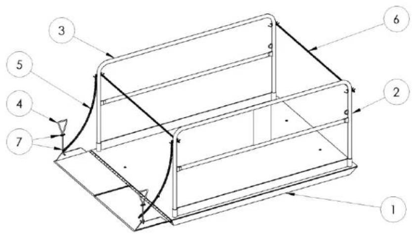
WL-100 Platform Service Components
| ITEM | PART NUMBER | DESCRIPTION | QTY |
| 1 | -- | PLATFORM | 1 |
| 2 | 05-524-001 | RIGHT SIDE HANDRAIL FOR 8' PLATFORMS | 1 |
| 05-524-002 | RIGHT SIDE HANDRAIL FOR 10' PLATFORMS | ||
| 05-524-003 | RIGHT SIDE HANDRAIL FOR 12' PLATFORMS | ||
| 3 | 05-524-004 | LEFT SIDE HANDRAIL FOR 8' PLATFORMS | 1 |
| 05-524-005 | LEFT SIDE HANDRAIL FOR 10' PLATFORMS | ||
| 05-524-006 | LEFT SIDE HANDRAIL FOR 12' PLATFORMS | ||
| 4 | 05-025-301 | HANDLE, WL-100 BRIDGE HANDLE | 2 |
| 5 | 08-145-029 | CHAIN, 48" LG | 2 |
| 6 | 08-145-029 | CHAIN FOR 4' WIDE PLATFORMS | 2 |
| 99-145-026 | CHAIN FOR 6' WIDE PLATFORMS | ||
| 99-145-098 | CHAIN FOR 7' WIDE PLATFORMS | ||
| 99-145-087 | CHAIN FOR 8' WIDE PLATFORMS | ||
| 7 | 99-145-055 | 1/4" QUICK LINK | 4 |
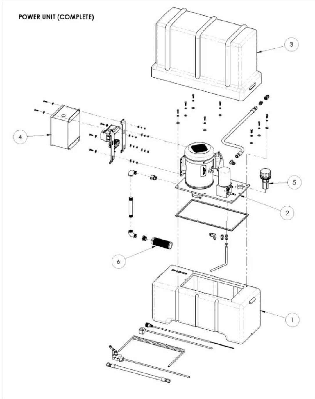
WL-100 Power Unit Assembly Bill of Materials
| ITEM | DESCRIPTION |
| 1 | HYDRAULIC RESERVOIR |
| 2 | MOTOR/PUMP SUBASSEMBLY (99-160-225) |
| 3 | COVER |
| 4 | ELECTRICAL ENCLOSURE |
| 5 | OIL FILLER/BREATHER (99-031-036) |
| 6 | INLET STRAINER (99-031-035) |
* See separate illustrations and tables for detailed parts lists
Space intentionally blank.
MOTOR/PUMP SUBASSEMBLY

MOTOR/PUMP SUBASSEMBLY (99-160-225 Rev. A)
| ITEM | PART NUMBER | DESCRIPTION | QTY |
| 1 | 22-031-027 | HYDRAULIC PUMP ADAPTER, 20" | 1 |
| 2 | 99-135-036 | MOTOR, 6.5 HP, 3 PH, 1750 RPM, 184T, 208-230/460V, 60 HZ, ELECTRIC, 9T SHAFT | 1 |
| 3 | 05-143-005 | PUMP, HYDRAULIC GEAR | 1 |
| 4 | 11107 | HEX BOLT, GRADE A, ZINC FINISH, 3/8"-16 x 1-1/4" | 2 |
| 5 | 11205 | HEX BOLT, GRADE A, ZINC PLATED, 1/2"-13X 1" | 4 |
| 6 | 33008 | FLAT WASHER, LOW CARBON, USS, ZINC PLATED, 3/8" | 2 |
| 7 | 33622 | SPLIT LOCK WASHER, CARBON STEEL, MEDIUM ZINC FINISH, 3/8" | 2 |
| 8 | 33626 | LOCK WASHER Z PLATED, ∅ 1/2 | 4 |
| 9 | 37024 | NYLON INSERT LOCK NUT, GRADE 2, ZINC FINISH, 3/8"-16 | 2 |
| 10 | 05-627-012 | ASSEMBLY, MANIFOLD | 1 |
| 11 | 11055 | HEX BOLT, GRADE A, ZINC PLATED, 5/16-18 X 1 | 4 |
| 12 | 33620 | LOCK WASHER, MEDIUM SPLIT, ∅5/16" | 4 |
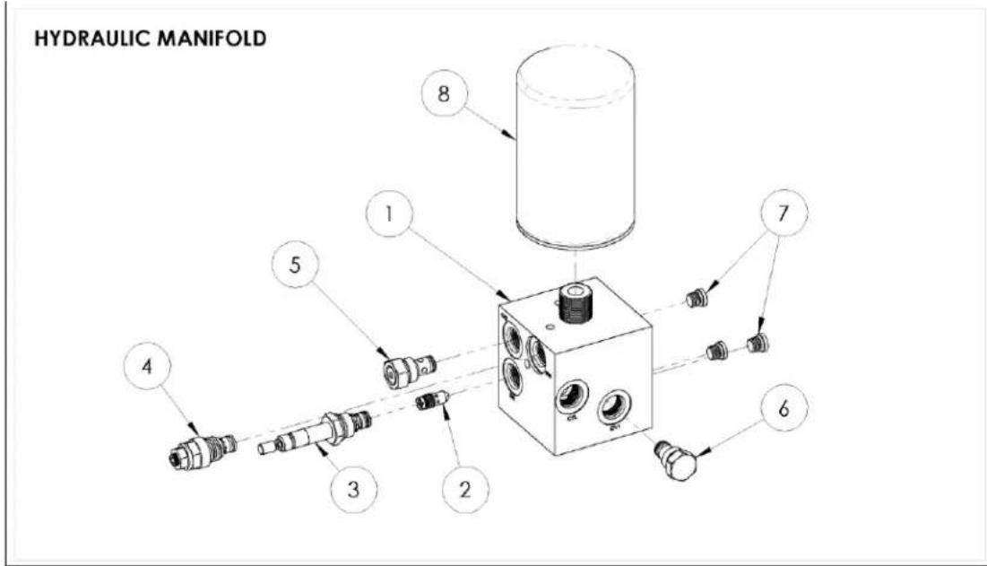

MANIFOLD ASSEMBLY AND HYDRAULIC SCHEMATIC (05-627-012 Rev. A)
| ITEM | PART NUMBER | DESCRIPTION | QTY |
| 1 | 05-127-010 | MANIFOLD, HYDRAULIC | 1 |
| 2 | 99-153-041-001 | FLOW CONTROL, PRES. COMP., 3.2 GAL | 1 |
| 3 | 99-153-016 | VALVE, CARTRIDGE, N.C., W/ MANUAL OVERRIDE, SIZE 08 | 1 |
| 4 | 99-153-006 | VALVE, PRESSURE RELIEF, 210 BAR | 1 |
| 5 | 99-153-068 | VALVE, CHECK, NOSE-IN/SIDE-OUT, 25 PSI | 1 |
| 6 | 99-153-011 | CHECK VALVE, SIZE 08, NOSE-IN/SIDE-OUT | 1 |
| 7 | 99-116-005 | FITTING, HYDRAULIC, 04MORB HOLLOW HEX PLUG | 3 |
| 8 | 22-031-007 | RESERVOIR, FILTER, HYDRAULIC, SPIN-ON, 1"-12 THREAD, 10 MICRON | 1 |
ELECTRICAL SYSTEM DIAGRAMS
WARNING
Care should be taken to identify all potential hazards and comply with applicable safety procedures before beginning work. Ensure that all system pressure and electrical power have been removed before attempting to work on the electrical or hydraulic systems. Follow all applicable lockout/tagout procedures.
WARNING
The load must be removed, and the platform either positively and adequately supported or fully lowered, before any work is performed on the Dock Lift.
Only qualified individuals trained to understand mechanical devices and their associated electrical and hydraulic circuits, as well as the hazards associated with them, should attempt troubleshooting and repair of this equipment.
Three-Phase Electric Circuit Diagram, 1/2 (05124024 Rev. C)
Note: Overcurrent & short circuit protection and disconnect must be provided by end user per the NEC (NFPA 70) and local codes.
OVERCURRENT & SHORT-CIRCUIT PROTECTION, AND DISCONNECT ARE TO BE PROVIDED BY THE END-USER PER THE NEC (NEPA 70) AND LOCAL CODES.


BE SURE ALL POWER IS OFF BEFORE ATTEMPTING TO WORK ON THIS EQUIPMENT!
CAUTION: SERVICE WORK SHOULD BE PERFORMED ONLY BY TRAINED & QUALIFIED PERSONNEL
* Number of toe guard switches can vary according to platform size.
Three-Phase Electric Circuit Diagram, 2/2 (05124024 Rev. C)
Note: Overcurrent & short circuit protection and disconnect must be provided by end user per the NEC (NFPA 70) and local codes.

Motor Lead Connections (99124021).
Applicable to all 2 HP, 5.5 HP, and 6.5 HP three-phase motors.

L1 L2 L3
![graph TD A["1"] --> B["460 VAC, 3-PHASE"] C["2"] --> B D["3"] --> B E["7"] --> B F["8"] --> B G["9"] --> B H["4"] --> B I["5"] --> B J["6"] --> B K["*THERMOSTAT"]](/content/2026/07/1460263/images/4062edb7fba95aaaebfe7f8b9893a534abc82c7c6c043c7ff00508508da47aab.jpg)
L1 L2 L3
* The two thermostat leads go to (1) the grounded side of the transformer secondary, and; (2) the motor relay coil.
Polarity across the thermostat leads may be reversed.

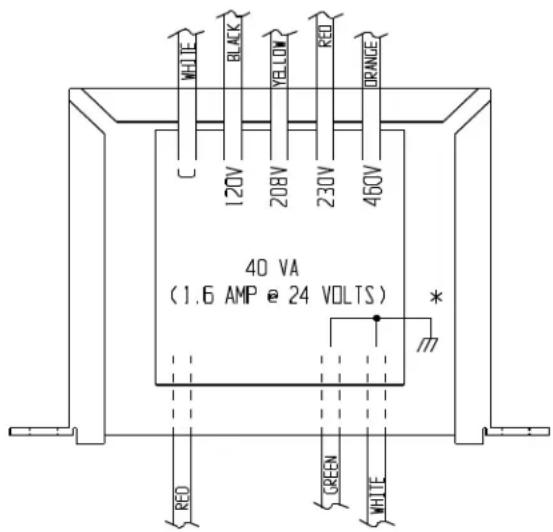
When changing the motor voltage configuration, you must also change the configuration of the control transformer to match the motor voltage.
Control Voltage Transformer (01129001 Rev. G).
INSTALLATION INSTRUCTIONS
Review this entire section before installing the Dock Lift.
Consult the factory in the event of questions or problems at the time of installation.
Modifications or additions to the Lift, without prior authorization by the manufacturer, automatically voids the warranty. See ANSI standard MH29.1-2003, Safety Requirements for Industrial Scissor Lifts, Section 12.6. Attaching ancillary equipment to the platform will lower its load capacity.
The installation shall comply with all applicable regulations for its location and use.
The end user is responsible for verifying that this lift table and its installation are suitable for its environment and application.
An architectural or engineering review of the planned installation is recommended.
This Lift shall be installed only by qualified and trained personnel with access to appropriate equipment. Electrical connections shall be performed by a qualified electrician.
Before You Begin.
The Dock Lift must be anchored to a smooth, level, and adequately strong concrete surface.
For pit installations, first determine where and how the electrical and/or hydraulic connections will be made when the Lift is in place. Reference the PIT DIAGRAM and dimensions table to plan your installation.
For installations using an approach ramp, ensure that there is adequate clearance beyond the ramp for equipment using the ramp, such as forklifts or pallet trucks.
Tools And Supplies.
The following tools and supplies may be needed to install your Dock Lift. These items are not supplied with the product.
- A fork truck or hoist and rigging, capable of unloading the Dock Lift and setting it in place. Weights vary from 2800 lb to 6700 lb, depending on model.
- A masonry drill and bits; hand tools, grout, and steel shims.
- A smooth, level concrete surface on which to mount the Scissor Lift.
- Eight 3/4 concrete anchors. The customer is responsible for selecting anchors appropriate for the Dock Lift model and concrete floor conditions. DO NOT operate an unsecured Scissor Lift.
- Five wires, 18 AWG or larger, or an appropriate hard service cable, 8 feet long. These connect the power unit enclosure to the Dock Lift frame.
- A power supply and electrical disconnect matching the pump motor's voltage and current requirements. Refer to the Dock Lift's data plate, labels on the control enclosure, and the electrical diagrams in this manual for more information. The end-user is responsible for supplying the required ground-fault and short-circuit protection on the supply. Motor overload protection is provided by a thermostat built into the motor.
- For pit installations, a minimum 2" conduit installing in the pit wall or floor to allow wire and hose access. Electrical lines are low-voltage (24 VAC), and may share a conduit with the hydraulic lines except where prohibited by local codes. Conduit shall have a minimum bend radius of 10". A pit drain should be installed. The end-user is responsible for purchasing materials and constructing the pit.
Pit Dimensions.

| MODEL | PIT DIMENSIONS | PREFERRED DRAIN LOCATION3 | ||||||||
| L11/2 | L22 | W11 | W2 | D | E | L3 | W3 | C | G | |
| WL-100-5-48 | 99 1⁄2" | 17 1⁄4" | 50" | 50" | 8 1⁄4" | 20 13/16" | 87" | 30°/8" | 5" | 15 1⁄4" |
| WL-100-5-68 | 99 1⁄2" | 17 1⁄4" | 74" | 74" | 8 1⁄4" | 23 1⁄4" | 87" | 52" | 5" | 16" |
| WL-100-5-78 | 99 1⁄2" | 17 1⁄4" | 86" | 74" | 8 1⁄4" | 29 1⁄4" | 87" | 52" | 5" | 16" |
| WL-100-5-88 | 99 1⁄2" | 17 1⁄4" | 98" | 74" | 8 1⁄4" | 24" | 87" | 76'/16" | 5" | 16" |
| WL-100-5-610 | 123.5 | 17 1⁄4" | 74" | 74" | 8 1⁄4" | 23 1⁄4" | 111" | 52" | 20 1⁄2" | 16" |
| WL-100-5-710 | 123.5 | 17 1⁄4" | 86" | 74" | 8 1⁄4" | 29 1⁄4" | 111" | 52" | 20 1⁄2" | 16" |
| WL-100-5-810 | 123.5 | 17 1⁄4" | 98" | 74" | 8 1⁄4" | 24" | 111" | 76'/16" | 20 1⁄2" | 16" |
| WL-100-6-68 | 99 1⁄2" | 17 1⁄4" | 74" | 74" | 10 1⁄4" | 23 1⁄4" | 87" | 52" | 5" | 16" |
| WL-100-6-78 | 99 1⁄2" | 17 1⁄4" | 86" | 74" | 10 1⁄4" | 29 1⁄4" | 87" | 52" | 5" | 16" |
| WL-100-6-88 | 99 1⁄2" | 17 1⁄4" | 98" | 74" | 10 1⁄4" | 24" | 87" | 76'/16" | 5" | 16" |
| WL-100-6-610 | 123.5 | 17 1⁄4" | 74" | 74" | 10 1⁄4" | 23 1⁄4" | 111" | 76'/16" | 20 1⁄2" | 16" |
| WL-100-6-710 | 123.5 | 17 1⁄4" | 86" | 74" | 10 1⁄4" | 29 1⁄4" | 111" | 76'/16" | 20 1⁄2" | 16" |
| WL-100-6-810 | 123.5 | 17 1⁄4" | 98" | 74" | 10 1⁄4" | 24" | 111" | 76'/16" | 20 1⁄2" | 16" |
| WL-100-8-68 | 99 1⁄2" | 17 1⁄4" | 74" | 74" | 10 1⁄4" | 23 1⁄4" | 87" | 52" | 5" | 16" |
| WL-100-8-78 | 99 1⁄2" | 17 1⁄4" | 86" | 74" | 10 1⁄4" | 29 1⁄4" | 87" | 52" | 5" | 16" |
| WL-100-8-88 | 99 1⁄2" | 17 1⁄4" | 98" | 74" | 10 1⁄4" | 24" | 87" | 76'/16" | 5" | 16" |
| WL-100-8-610 | 123.5 | 17 1⁄4" | 74" | 74" | 10 1⁄4" | 23 1⁄4" | 111" | 76'/16" | 20 1⁄2" | 16" |
| WL-100-8-710 | 123.5 | 17 1⁄4" | 86" | 74" | 10 1⁄4" | 29 1⁄4" | 111" | 76'/16" | 20 1⁄2" | 16" |
| WL-100-8-810 | 123.5 | 17 1⁄4" | 98" | 74" | 10 1⁄4" | 24" | 111" | 76'/16" | 20 1⁄2" | 16" |
| WL-100-10-68 | 99 1⁄2" | 17 1⁄4" | 74" | 74" | 14 1⁄4" | 23 1⁄4" | 87" | 52" | 5" | 16" |
| WL-100-10-78 | 99 1⁄2" | 17 1⁄4" | 86" | 74" | 14 1⁄4" | 29 1⁄4" | 87" | 52" | 5" | 16" |
| WL-100-10-88 | 99 1⁄2" | 17 1⁄4" | 98" | 74" | 14 1⁄4" | 24" | 87" | 76'/16" | 5" | 16" |
| WL-100-10-610 | 123.5 | 17 1⁄4" | 74" | 74" | 14 1⁄4" | 23 1⁄4" | 111" | 52" | 20 1⁄2" | 16" |
| WL-100-10-710 | 123.5 | 17 1⁄4" | 86" | 74" | 14 1⁄4" | 29 1⁄4" | 111" | 52" | 20 1⁄2" | 16" |
| WL-100-10-810 | 123.5 | 17 1⁄4" | 98" | 74" | 14 1⁄4" | 24" | 111" | 76'/16" | 20 1⁄2" | 16" |
| WL-100-10-612 | 147.5 | 171/4" | 74" | 74" | 141/4" | 231/4" | 111" | 52" | 201/2" | 16" |
| WL-100-10-712 | 147.5 | 171/4" | 86" | 74" | 141/4" | 291/4" | 111" | 52" | 201/2" | 16" |
| WL-100-10-812 | 147.5 | 171/4" | 98" | 74" | 141/4" | 24" | 111" | 76'/16" | 201/2" | 16" |
| WL-100-12-68 | 991/2" | 171/4" | 74" | 74" | 141/4" | 231/4" | 87" | 52" | 5" | 16" |
| WL-100-12-78 | 991/2" | 171/4" | 86" | 74" | 141/4" | 291/4" | 87" | 52" | 5" | 16" |
| WL-100-12-88 | 991/2" | 171/4" | 98" | 74" | 141/4" | 24" | 87" | 76'/16" | 5" | 16" |
| WL-100-12-610 | 123.5 | 171/4" | 74" | 74" | 141/4" | 231/4" | 111" | 52" | 201/2" | 16" |
| WL-100-12-710 | 123.5 | 171/4" | 86" | 74" | 141/4" | 291/4" | 111" | 52" | 201/2" | 16" |
| WL-100-12-810 | 123.5 | 171/4" | 98" | 74" | 141/4" | 24" | 111" | 76'/16" | 201/2" | 16" |
| WL-100-12-612 | 147.5 | 171/4" | 74" | 74" | 141/4" | 231/4" | 111" | 52" | 201/2" | 16" |
| WL-100-12-712 | 147.5 | 171/4" | 86" | 74" | 141/4" | 291/4" | 111" | 52" | 201/2" | 16" |
| WL-100-12-812 | 147.5 | 171/4" | 98" | 74" | 141/4" | 24" | 111" | 76'/16" | 201/2" | 16" |
Notes: 1 Dimension is +0/-1".
2 With Aluminum Bridge option (AL-ADDSATB), add 5" to L1 dimension, 2 1/4 " to L2 dimension.
3 Preferred drain region indicates where the Lift's base structure will not cover the drain. Install pit drains to suit local codes and weather conditions.
Installation.
- For pit installations, verify that the pit conforms to the pit diagram.
- Place the power unit in the desired location. The standard 8-foot hose allows the power unit to be mounted adjacent to the Dock Lift.
- For pit installations, feed the required electric and hydraulic lines through the conduit.
- Remove the cover from the power unit.
- Have a qualified electrician connect the end-user's power supply to the power unit's motor relay (M1 on the Electrical Diagram, p. 14). Verify that the supply voltage matches that listed on the Dock Lift data plate (located on the right side of the platform). Verify that the control transformer (1T) primary lead wiring corresponds to the supply voltage.
- Remove all steel strapping and shipping materials from the Lift. Remove the lag screws holding the Lift to its shipping pallet. Leave the eyebolts protruding through the deck in place.
- Use rigging to lift the Dock Lift by the eyebolts. Move the Lift into position.
a. For pit installations, connect the hydraulic hose from the conduit to the quick-connect fitting on the Lift's frame before fully lowering the Lift into the pit. Take care to avoid damaging the hose or electrical wires coming from the conduit.
b. For floor installations, the hydraulic hose may be connected after positioning the Lift.
-
REMOVE THE EYEBOLTS PROTRUDING THROUGH THE PLATFORM. The eyebolts will prevent the Lift from operating.
-
Install the handrails on the platform.
-
Open the accessory bag.
a. Remove one handle-chain-snap link subassembly from the accessory bag. Attach one snap link to the cold shut link on the handrail above the bridge; attach the other snap link to the hole in the bridge side rail. Repeat for the second handle-chain-snap link subassembly.
b. Attach one loose quick link to the end of the loose chain. Hang the chain across one end of the handrails. Repeat for the other end of the platform.
c. Connect the pendant control cord to the plug on the power unit.
-
Open the electrical enclosure. Install a jumper wire from terminal #3 to terminal #4 (1 TB).
-
Apply electrical power to the Lift. Use the pendant control to raise the platform just high enough to allow both safety maintenance props to be flipped up into the frame.
SAFETY PROP LOCATIONS

SAFETY PROP OUT

SAFETY PROP IN

Note: The WL-100-5-48, WL-100-10-###, and WL-100-12-### models use a drop-in safety prop (P/N 05-537-305). The drop-in safety props may be stored on the platform toe rail.
DROP-IN SAFETY PROP
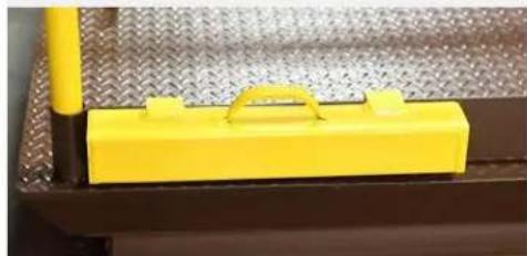
- Manually lower the legset until the rollers rest against the maintenance props.
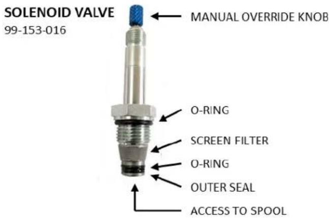
a. On the power unit, locate the manual override knob for the solenoid valve (illustration).
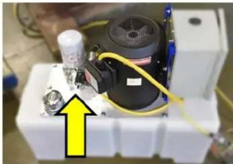
b. Push the knob in and twist counterclockwise to open the valve. This allows the Lift's platform to lower.

Make sure personnel are clear of the scissor leg set before lowering the platform!
c. Push the knob in and twist clockwise to close the valve.
Always close the manual valve override before operating the Dock Lift.


-
Remove electrical power from the Lift.
-
Remove the jumper wire between terminal #3 and terminal #4.
-
Connect the customer-supplied wires from the enclosure terminal block to the junction box on the frame. Five 18AWG wires are required (four signals, one ground). Connect the wires as shown in the wiring diagram. Be careful to not confuse the two black wires in the junction box – they are not interchangeable!
-
Close and secure the electrical enclosure door. Place the cover back on the power unit. Re-apply electrical power to the Lift.
-
Verify that the toe guard strips move freely. Verify that the electrical switch in the middle of each strip is not actuated.
-
Raise the platform to a 60-inch height, as measured from the bottom of the frame. Adjust the upper limit switch arm (mounted on the non-bridge end of the frame, below) so that it switches at this platform height.

-
Bleed the hydraulic cylinders. Follow the procedure in the INSPECTION AND MAINTENANCE section, page 25.
-
Flip or remove the maintenance props out from the rails. Fully lower the platform using the pendant control. Continue holding the DOWN pushbutton for several seconds after the platform reaches bottom. This allows any air trapped in the hoses to leave the system via the reservoir.
-
While lowered, check the platform for the proper lowered height. For pit installations, make sure the platform is flush with the ground surface. Remedy any trip hazards caused by a floor level change of 1/4 " (6 mm) or more.
-
Raise the Lift. Flip or lower the maintenance props back into the legs. Lower the Lift until the leg set rests against the props.
-
Anchor the frame to the floor through the four mounting holes at the corners of the frame.
-
Shim and/or grout to ensure the entire length of both base side frames are level and fully supported. The entire length of base frame rail must be fully supported with no gaps in its foundation for the Lift to function properly.
-
Operate the lift table through several full raise and lower cycles. Verify that actuating the upper travel limit switch (mounted on the base frame) prevents further upward travel of the platform. Verify that actuating the perimeter toe guard switches (under the platform) from any side of the lift table prevents further downward travel of the platform. DO NOT place a lift table in service if either of these devices isn't functioning properly.

PERIMETER TOE GUARD (UNDER PLATFORM EDGE)
UPPER TRAVEL
LIMIT SWITCH
- Check the hydraulic oil level. It should be filled to within 3" (75 mm) of the top of the reservoir. If oil is needed, use an anti-wear hydraulic oil with a viscosity grade of 150 SUS at 100°F (ISO 32 at 40°C) or a non-synthetic automatic transmission fluid.
- Clean up any debris or spilled oil. Verify that all of the information, safety, and warning labels are in good condition.
- If installing the optional approach ramp, put it in position, leaving a gap of 1/4 " -1" (6 mm – 25 mm) between it and the Lift platform. Anchor the ramp to the floor.
RECORD OF SATISFACTORY CONDITION
After assembling and installing the Dock Lift, and before using it for the first time, make a record describing its appearance. Thoroughly photograph the Lift from multiple angles, including all welds and anchor points, and all labeling applied to it. Describe where each label is located. Collect all photographs and writings into a file. Mark the file appropriately to identify it. This record documents satisfactory condition. Compare the results of future inspections to this record to determine if the Lift is in satisfactory condition. Do not use the Lift unless it is in satisfactory condition. Purely cosmetic changes, like damaged paint or powder coat, do not constitute changes from satisfactory condition. However, touchup paint should be applied to all affected areas as soon as damage occurs.
OPERATION INSTRUCTIONS
Consult ANSI standard MH29.1 (Industrial Scissor Lifts), Section 12 for the owner's/user's responsibilities regarding the operation, care, and maintenance of this Dock Lift.
The user shall ensure that operators understand that safe operation of the Lift is the operator's responsibility. The user shall also ensure that operators are knowledgeable of, and observe, the safety rules and practices in this section.
The Premium Truck Scissor Dock Lift is suitable for indoors and outdoors use in most non-classified industrial locations and many commercial locations. It is intended to lift freight and material handling equipment, such as pallet jacks and fork trucks, for loading and unloading box trucks and semi trailers.
WARNING
This Dock Lift is not intended, and DOES NOT meet ANSI standards, for service as: a lift platform for passengers; a vertical lift for mobility impaired persons; an elevated work platform, or; a vehicle service lift. DO NOT use the Lift for purposes other than lifting or lowering freight and equipment to and from a truck.
While not intended to carry passengers, a forklift driver or other qualified person, trained in the proper use of the Lift, may accompany equipment and freight on the Lift platform. No more than two people should be on the Lift while it is in motion.
The drawing identifies the major components of your Lift.

Inspection.
Inspect the Lift's perimeter toe guard for correct operation at the beginning of every shift. First raise the platform. Push and hold a section of the perimeter toe guard up against the platform. The platform should not move when the "LOWER" button is pressed. Perform this check on all four sides of the platform.
Check the condition of the guards, controls, scissor mechanism, hydraulic lines, and limit switches. If any item is in need of repair or otherwise contributes to an unsafe condition, remove the Lift from service until it has been restored to a safe operating condition. See the section on Inspection and Maintenance, p. 25.
Loading the platform.
The load rating, in pounds, is shown on the machine data plate located on the bridge plate end of the platform. This indicates the net capacity of the Dock Lift for a static load, centered and evenly distributed on the platform. Consult ANSI MH29.1, Section 3, for loading definitions.
Take care to balance loads on the platform. The Lift's maximum single-axle load is 65% of the rated capacity for side loading, and 75% for end loading (see diagram).

To prevent shifting of loads, engage parking brakes and/or wheel locks for any rolling equipment placed on the Lift.
Cross-traffic loads up to twice the Lift's capacity are allowed with the platform fully lowered. Do not exceed a travel speed of two feet per second when moving loads across the platform. Do not actuate the Lift while a load is in motion on the platform.

DO NOT exceed the lift table's load ratings. Injury to personnel or permanent damage to the lift table can result from exceeding the listed capacity. Take into account the weight of any equipment added to the platform by the user or third parties when determining the maximum working load to be placed on the platform.

The platform rollers are not captured. DO NOT overhang any load over the side of the platform. A cantilevered or overhanging load at the hinged end can cause the platform to tilt and dump the load. For applications involving side or end edge loading, consult the factory.
Operating the lift.
The Dock Lift is furnished with an external electric-hydraulic power unit and a handheld pushbutton control.
- Place the safety chains across the openings on both ends of the Lift.
- Make sure both bridge segments are raised.
- Press the “RAISE” pushbutton to energize the pump motor and raise the platform to the level of the truck. The platform will rise only while the pushbutton is pressed. When the pushbutton is released, the platform will stop and hold its position. The upper travel limit switch prevents upward travel beyond the platform’s maximum height.
- Use the handles to lower the bridge segments onto the truck's deck. If necessary, adjust the platform height to match that of the truck.
- Remove the safety chain between the platform and the truck. Load/unload the truck.
- When ready to lower the platform, place the safety chain back over the truck-side opening. Use the handles to lift both bridge segments.
- Press the “LOWER” pushbutton to open the hydraulic valve and lower the platform. Take care to prevent the cord from becoming pinched in the legset mechanism. The platform descends by gravity, and the pump motor will not run. Release the pushbutton to stop the motion of the platform. If the perimeter toe guard encounters an object, the valve will close and will prevent further descent of the platform.
- The WL-100 Lift is provided with hydraulic overload protection that will prevent it from raising a load in excess of its rated capacity. Its lowering speed is preset at the factory, and will not exceed a speed of 30 fpm. In the event of a hydraulic line failure, a velocity fuse internal to the cylinder will prevent the platform from lowering.
- In the event of a power failure, the Lift may be manually lowered. Follow the procedure for manually lowering the lift, p. 20.


Always watch the area around the platform and any load on the platform when it is in operation.

Never use the Dock Lift if any damage or unusual noise is observed, if it is in need of repair, or if any other malfunction is observed. Notify your supervisor or maintenance personnel.

Keep all personnel clear of the Lift when it is in operation. Before operating the Lift, make certain no part of any person or object is under the platform.
All guards shall be in place before operating the Lift.

Guards cannot protect against every possible condition, and should not be considered a substitute for good judgment and care in use, loading, handling, storage, etc. of the Dock Lift.
INSPECTION AND MAINTENANCE
Proper maintenance is essential for maximizing the service life of this product. If an inspection reveals any irregularities in the Dock Lift's condition, repair it before returning it to service. Only use manufacturer-approved replacement parts. Contact Technical Service if you have questions that are not addressed in these instructions or if you are uncertain how to address an issue discovered during an inspection. Technical Service can be contacted by calling (260) 665-7586 and asking for the Service and Parts Department or by submitting questions online at http://www.vestilmfg.com/parts_info.htm.
WARNING
Care should be taken to identify all potential hazards and comply with applicable safety procedures before beginning work.
WARNING
Remove any load and install the maintenance props before beginning any inspection or service on the Lift. See below.
Only qualified individuals trained to understand mechanical devices, electrical and hydraulic circuits, and the hazards associated with them, should attempt troubleshooting and repair of this equipment.
Inspection procedures.
Prior to performing any inspection or maintenance on this Lift:
- Read and understand these maintenance procedures.
- Remove the load from the platform. Do not attempt to service a loaded Dock Lift.
- Fully lower the platform, OR use both maintenance props to support the weight of the platform. To use the maintenance props, raise the platform to its full height. Rotate both props over to the inside of the frame rail (or place the drop-in props in front of the rollers, against the front edge of the base). Lower the platform until the rollers roll up against the props.
- Disconnect power. Follow established lockout/tagout policies as required.
Initial inspection.
Prior to use, any new, altered, modified, or repaired Scissor Dock Lift shall be inspected by a qualified person. Complete both the daily and monthly inspection items before releasing the Lift for regular use.
Daily inspection.
At the beginning of every shift, a designated person shall complete these inspections. Remove the lift table from service and repair or replace any damaged parts if any of the following is found.
1. Look for:
a. Frayed wires.
b. Oil leaks.
c. Pinched, chafed, worn, or cracking hydraulic hoses.
d. Damage, deformation, or cracks in any structural member or any weld. Give special attention to the hydraulic cylinder mounting brackets.
e. Loose or missing fasteners.
f. Unusual noise or evidence of binding.
- Test the function of the upper travel limit switch and the perimeter toe guard.
Monthly inspection.
Have a qualified person inspect for:
- Oil level. The oil should be within 3" below the top of the reservoir with the platform fully lowered. See the Annual Inspection section for the hydraulic oil specification.
- Worn or damaged hydraulic hoses or electrical wires.
- Wear in the pivot points on the legs. Apply grease to all pivot points.
- Looseness or wear in the rollers. Apply grease to all rollers.
- Integrity of the retaining hardware on all rollers and all pivot point pins.
- Integrity of the frame anchor bolts, and for cracks in the concrete around them.
- Proper functioning of the control pendant.
- Functional integrity of bridge lift chains, handles, and safety chains.
- Unusual noises or movement during operation.
- Condition of all information, safety, and warning labels. These should be clean and clearly legible.
- Dirt and debris. Clean, sweep, or wipe down as needed.
Annual inspection.
Check the condition of the oil. Change the oil if it darkens, becomes gritty, or turns a milky color (indicating the presence of water). Replace with an anti-wear hydraulic oil with a viscosity grade of 150 SUS at 100° F (ISO 32 cSt @ 40° C), such as AW 32, HO 150 or Dexron non-synthetic transmission fluid. You may use a synthetic transmission fluid if you flush the system with the synthetic fluid before filling the reservoir. 150 SUS at 100° F (ISO 32 cSt @ 40° C) or Dexron transmission fluid.
Solenoid valve maintenance.
In the event that the platform creeps down slowly after releasing the “DOWN” control, it will be necessary to remove the lowering cartridge valve for inspection and cleaning.
- Remove all loads from the platform.
-
Remove the cover from the power unit. Locate the manifold body.
-
Raise the platform. Rotate or place the maintenance props into the side frame. Lower the platform until the rollers rest against the props.
-
Remove the nut holding the solenoid coil on the solenoid valve stem (item (1), right). Remove the coil (2), then unscrew the valve from the manifold. Have a clean rag ready to contain any fluid that may leak from the opening.
-
Inspect the valve for contaminants. Inspect the O-rings and back-up washers for cuts, tears, or other damage.
-
With the valve immersed in mineral spirits or kerosene, insert a thin tool such as a small screwdriver or a small hex wrench in the hole at the bottom of the valve (illustration, next page). Push the spool in and out several times. A properly functioning spool should move freely, with about 1/16" of travel. Use mineral spirits to flush the valve.

-
If the spool continues to stick, the stem could be bent. The valve will need to be replaced.
-
Blow the valve off with a compressed-air gun while again pushing the spool in and out.
-
Inspect the bottom of the manifold's valve cavity for contaminants.
-
Make sure both O-rings and outer seal (flat) are seated on the valve body. Make sure the screen filter is in place and seated at the bottom of the threads on the valve body (illustration).
-
Reinstall the solenoid valve, tightening to 20 ft-lb of torque. Reattach the solenoid coil and the retaining nut.
Bleeding the hydraulic cylinders.
Air can enter the hydraulic system at any time its components are opened for service. Symptoms of air in the system include erratic or bouncing motion of the platform, sponginess in holding position, unusual noises, or foaming in the hydraulic fluid. Trapped air can also trigger the cylinder's velocity fuse, slowing or preventing the cylinder from lowering.
Cycling the platform up and down without a load can expel much of the trapped air through the hydraulic reservoir. If it becomes necessary to bleed air:
- It is best to open the bleeder valves on all cylinders simultaneously in order to bleed the valves. A two-person team is recommended.
- Remove all loads from the platform.
- Raise the platform. Rotate or lower the maintenance props into the side frame. Lower the platform until the rollers are about 1" away from props. Some motion is necessary to expel air from the system.
- Locate the bleeder valve on the top of each cylinder. Use a 1/4 " wrench to open each cylinder's bleeder valve about a half-turn. Hold a rag over the bleeder valve to capture expelled oil.
- Oil and air will sputter from the valves. Once no more air comes out, close the valves.
Space intentionally blank.
TROUBLESHOOTING GUIDE


Care should be taken to identify all potential hazards and comply with applicable safety procedures before beginning work.
Remove any load and install the maintenance props before beginning any inspection or service on the Dock Lift. See below.
Only qualified individuals trained to understand mechanical devices, electrical and hydraulic circuits, and the hazards associated with them, should attempt troubleshooting and repair of this equipment.
Consult the factory for any problems not addressed in this manual. ALWAYS have the product serial number or model number on hand when calling the factory.
| PROBLEM | POSSIBLE CAUSES | ACTION |
| Power unit doesn't run when "UP" button is pressed. | Transformer fuse is blown. | Test with meter. Replace if bad. |
| No supply voltage. | Test with meter. Check fuses, breakers, and overloads to determine the cause | |
| Upper-travel limit switch is engaged or bad. | Inspect and test switch for Normally Closed operation (continuity broken when switch engaged). Replace if bad. | |
| Bad control transformer. | Check for 24 VAC at secondary. Replace if bad. | |
| Bad motor relay coil. | Test with meter. Replace if bad. | |
| Motor runs but platform doesn't move. Power unit not noisy. | Motor runs in wrong direction. | Verify the motor runs in the direction indicated by its sticker. If not, reverse any two of L1, L2, L3 leads. |
| Pump fails to produce pressure. | Consult factory. | |
| Motor hums or pump squeals. Platform does not move, or moves slowly. | Pump fails to produce pressure. | Consult factory. |
| Excess voltage drop to motor, due to power wire size too small, wire run to long, or incoming voltage too low. | Check the power installation for adequacy. Check the incoming voltage while the motor is running. Correct any problems found. | |
| Motor is "single-phasing". | Determine and correct cause of voltage loss on phase. | |
| Pressure relief valve opens at full pressure. | Check for structural damage or binding of the scissor legs, etc. Check for platform overload condition. | |
| Contamination holding open the lowering valve or the check valve. | Remove and inspect valves. Clean per instructions in the "Inspection and Maintenance" section, p.26. | |
| Platform raises, then drifts down. | Contamination holding open the lowering valve or the check valve. | Remove and inspect valves. Clean per instructions in the "Inspection and Maintenance" section, p.26. |
| Spongy or jerky platform movement. | Excessive air in the hydraulic cylinders. | Bleed air per procedure described in the "Inspection and Maintenance" section, p.27. |
| Platform won't lower. | Perimeter toe guard actuated. | Check for a toe guard extrusion or rubber corner that is stuck. Adjust as necessary. |
| Perimeter toe guard switch or wire broken. | Inspect visually; check with mutimeter. Repair as needed. | |
| Solenoid coil is bad. | Check with multimeter using the diode-check function. (Reading for ohms will not provide an accurate test of the coil). Replace if bad. | |
| Physical blockage of the mechanism. | Inspect for foreign material or objects blocking the scissors or the rollers. | |
| Solenoid valve, flow control, or suction hose screen plugged. | Remove and inspect valves. Clean per instructions in the "Inspection and Maintenance" section, p.26. | |
| Platform lowers too slowly. | Solenoid valve, flow control, or suction hose screen plugged. | Remove and inspect valves. Clean per instructions in the "Inspection and Maintenance" section, p.26. |
| Velocity fuse locking (indicated by platform only slowly creeping down). | Check for air in hydraulic system. Bleed air as needed. | |
| Flow control valve spool sticking. | Remove and inspect valves. Clean per instructions in the "Inspection and Maintenance" section, p.26. | |
| Platform lowers too quickly. | Flow control valve spool sticking. | Remove and inspect valves. Clean per instructions in the "Inspection and Maintenance" section, p.26. |
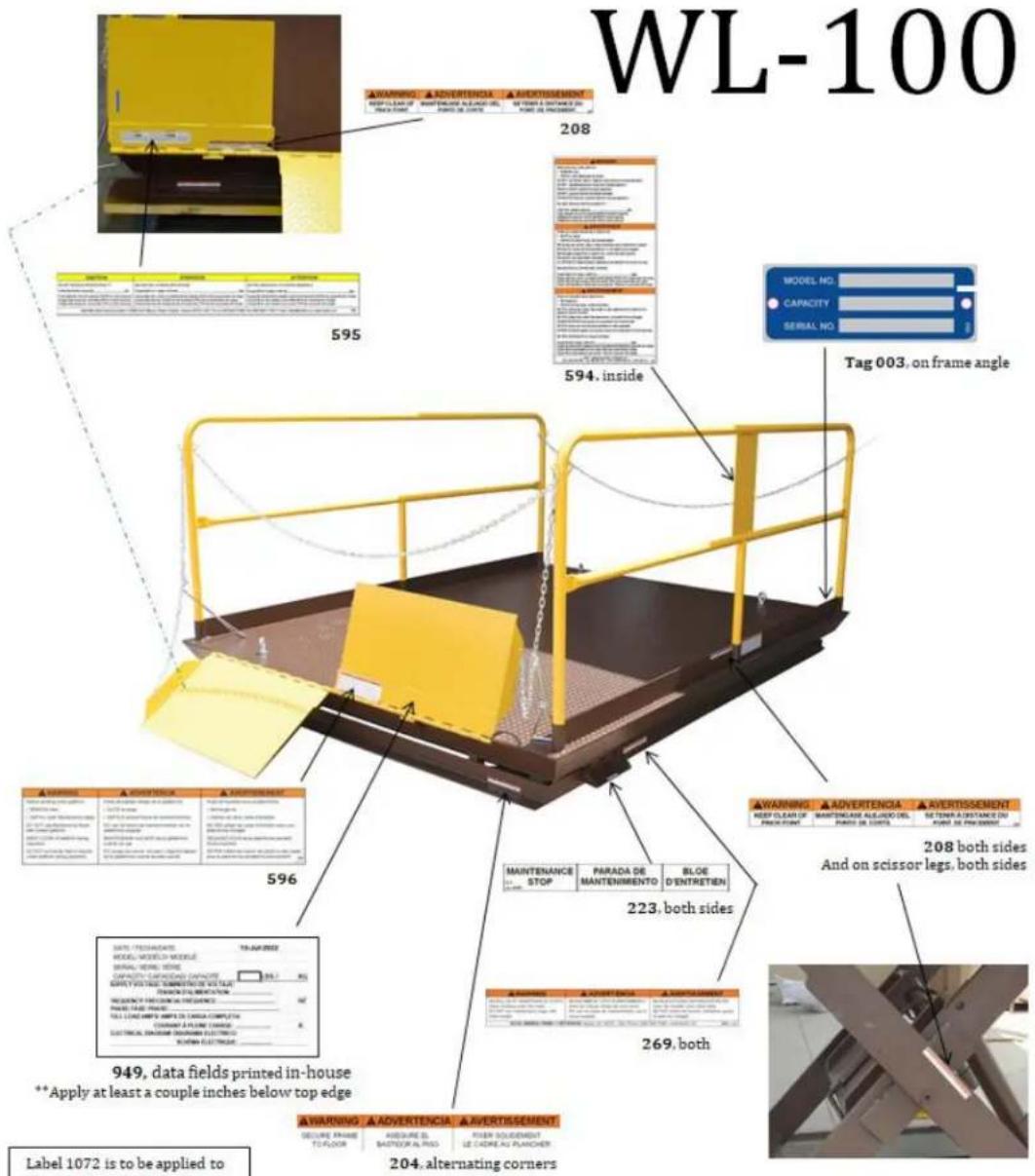
LABELING DIAGRAM
TheDock Lift should be labeled as shown in the diagrams. However, label content and location are subject to change so your product might not be labeled exactly as shown. Thoroughly photograph the Dock Lift when you first receive it as discussed in the Record of Satisfactory Condition section on p. 22. Make sure that your record includes a photograph of each label. Replace all labels that are or later become damaged, missing, or not easily readable (e.g. faded).
To order replacement labels, contact the technical service and parts department online at
http://www.vestilmfg.com/parts_info.htm. Alternatively, you may request replacement parts and/or service by calling
(260) 665-7586 and asking the operator to connect you to the Parts Department.
TRUCK SCISSOR DOCK LIFT
02/07/2025
LIMITED WARRANTY
Vestil Manufacturing Corporation ("Vestil") warrants this product to be free of defects in material and workmanship during the warranty period. Our warranty obligation is to provide a replacement for a defective, original part covered by the warranty after we receive a proper request from the Warrantee (you) for warranty service.
Who may request service?
Only a warrantee may request service. You are a warrantee if you purchased the product from Vestil or from an authorized distributor AND Vestil has been fully paid.
Definition of "original part"?
An original part is a part used to make the product as shipped to the Warrantee.
What is a "proper request"?
A request for warranty service is proper if Vestil receives: 1) a photocopy of the Customer Invoice that displays the shipping date; AND 2) a written request for warranty service including your name and phone number. Send requests by one of the following methods:
US Mail
| Vestil Manufacturing Corporation | (260) 665-1339 |
| 2999 North Wayne Street, PO Box 507 | Phone |
| Angola, IN 46703 | (260) 665-7586 |
Email
info@vestil.com
Enter "Warranty service request" in subject field
In the written request, list the parts believed to be defective and include the address where replacements should be delivered. After Vestil receives your request for warranty service, an authorized representative will contact you to determine whether your claim is covered by the warranty. Before providing warranty service, Vestil will require you to send the entire product, or just the defective part (or parts), to its facility in Angola, IN.
What is covered under the warranty?
The warranty covers defects in the following original, dynamic parts: motors, hydraulic pumps, motor controllers, and cylinders. It also covers defects in original parts that wear under normal usage conditions ("wearing parts"), such as bearings, hoses, wheels, seals, brushes, and batteries.
How long is the warranty period?
The warranty period for original dynamic components is 1 year. For wearing parts, the warranty period is 90 days. Both warranty periods begin on the date Vestil ships the product to the Warrantee. If the product was purchased from an authorized distributor, the periods begin when the distributor ships the product. Vestil may, at its sole discretion, extend a warranty period for products shipped from authorized distributors by up to 30 days to account for shipping time.
If a defective part is covered by the warranty, what will Vestil do to correct the problem?
Vestil will provide an appropriate replacement for any covered part. An authorized representative of Vestil will contact you to discuss your claim.
What is not covered by the warranty?
The Warrantee (you) are responsible for paying labor costs and freight costs to return the product to Vestil for warranty service.
Events that automatically void this Limited Warranty.
- Misuse;
- Negligent assembly, installation, operation or repair;
• Installation/use in corrosive environments; - Inadequate or improper maintenance;
• Damage sustained during shipping;
• Collisions or other accidents that damage the product;
• Unapproved modifications: Do not modify the product IN ANY WAY without first receiving written authorization from Vestil.
Do any other warranties apply to the product?
Vestil Manufacturing Corp. makes no other express warranties. All implied warranties are disclaimed to the extent allowed by law. Any implied warranty not disclaimed is limited in scope to the terms of this Limited Warranty. Vestil makes no warranty or representation that this product complies with any state or local design, performance, or safety code or standard. Noncompliance with any such code or standard is not a defect in material or workmanship.



- VESTIL MANUFACTURING CORP
- WL-100 SERIES PREMIUM TRUCK SCISSOR DOCK LIFT
- INSTRUCTION MANUAL
- RECEIVING INSTRUCTIONS
- NOTE
- REPLACEMENT PARTS AND TECHNICAL ASSISTANCE
- ELECTRONIC COPIES OF INSTRUCTION MANUALS
- HAZARDS
- NOTICE
- MODEL NUMBER AND CAPACITY
- EXPLODED ASSEMBLY VIEWS
- WL-100 POWER UNIT ASSEMBLY BILL OF MATERIALS
- ELECTRICAL SYSTEM DIAGRAMS
- WARNING
- THREE-PHASE ELECTRIC CIRCUIT DIAGRAM, 1/2 (05124024 REV. C)
- THREE-PHASE ELECTRIC CIRCUIT DIAGRAM, 2/2 (05124024 REV. C)
- MOTOR LEAD CONNECTIONS (99124021)
- INSTALLATION INSTRUCTIONS
- BEFORE YOU BEGIN
- TOOLS AND SUPPLIES
- PIT DIMENSIONS
- INSTALLATION
- RECORD OF SATISFACTORY CONDITION
- OPERATION INSTRUCTIONS
- INSPECTION
- LOADING THE PLATFORM
- OPERATING THE LIFT
- INSPECTION AND MAINTENANCE
- INSPECTION PROCEDURES
- INITIAL INSPECTION
- DAILY INSPECTION
- LOOK FOR
- MONTHLY INSPECTION
- ANNUAL INSPECTION
- SOLENOID VALVE MAINTENANCE
- BLEEDING THE HYDRAULIC CYLINDERS
- TROUBLESHOOTING GUIDE
- LABELING DIAGRAM
- LIMITED WARRANTY
- WHO MAY REQUEST SERVICE
- DEFINITION OF "ORIGINAL PART
- WHAT IS A "PROPER REQUEST
- WHAT IS COVERED UNDER THE WARRANTY
- HOW LONG IS THE WARRANTY PERIOD
- IF A DEFECTIVE PART IS COVERED BY THE WARRANTY, WHAT WILL VESTIL DO TO CORRECT THE PROBLEM
- WHAT IS NOT COVERED BY THE WARRANTY
- EVENTS THAT AUTOMATICALLY VOID THIS LIMITED WARRANTY
- DO ANY OTHER WARRANTIES APPLY TO THE PRODUCT
Brand : Vestil
Model : WL-100-6-710
Category : Plateforme élévatrice industrielle