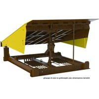
RR-68-50 - Niveauur de quai Vestil - Free user manual and instructions
Find the device manual for free RR-68-50 Vestil in PDF.


| Product Type | Drum Cradle |
| Model | RR-68-50 |
| Brand | Vestil |
| Capacity | 750 lb (340 kg) |
| Drum Compatibility | 55 gallon (208 L) steel or fiber drums |
| Overall Dimensions (L x W x H) | 30 in x 24 in x 18 in (76 cm x 61 cm x 46 cm) |
| Weight | 45 lb (20.4 kg) |
| Material | Heavy-duty steel |
| Finish | Powder coated yellow |
| Features | Tilting design for controlled pouring, roll-out base with swivel casters, drum retention strap, safety lock |
| Number of Casters | 4 (2 fixed, 2 swivel) |
| Caster Diameter | 4 in (10 cm) |
| Color | Yellow |
| Assembly Required | Yes |
| Warranty | 1 year limited |
| Safety Compliance | ANSI/ASME B30.20 |
| Uses | Handling and dispensing liquids from drums |
| Maintenance | Lubricate casters regularly, inspect for wear |
| Cleaning | Wipe with damp cloth; avoid abrasive cleaners |
| Spare Parts Availability | Contact Vestil for replacement casters and straps |
Frequently Asked Questions - RR-68-50 Vestil
User questions about RR-68-50 Vestil
0 question about this device. Answer the ones you know or ask your own.
Ask a new question about this device
Download the instructions for your Niveauur de quai in PDF format for free! Find your manual RR-68-50 - Vestil and take your electronic device back in hand. On this page are published all the documents necessary for the use of your device. RR-68-50 by Vestil.
USER MANUAL RR-68-50 Vestil
Vestil Manufacturing Corp.
2999 North Wayne Street, P.O. Box 507, Angola, IN 46703
Telephone: (260) 665-7586 -or- Toll Free (800) 348-0868
www.vestil.com info@vestil.com
RR-Series Dock Levelers

Receiving Instructions
After delivery, remove the packaging from the product. Inspect the product closely to determine whether it sustained damage during transport. If damage is discovered, record a complete description of it on the bill of lading. If the product is undamaged, discard the packaging.
NOTE: The end-user is solely responsible for confirming that product design, use, and maintenance comply with laws, regulations, codes, and mandatory standards applied where the product is used.
Technical Service & Replacement Parts
For answers to questions not addressed in these instructions and to order replacement parts, labels, and accessories, call our Technical Service and Parts Department at (260) 665-7586. The department can also be contacted online at https://www.vestil.com/page-parts-request.php.
Electronic copies of Instruction Manuals
Additional copies of this instruction manual may be downloaded from https://www.vestil.com/page-manuals.php.
TABLE OF CONTENTS
| Signal Words | 2 |
| Safety Instructions | 2 |
| RR-65, RR-66, RR-68, and RR-610 Exploded View & Bill of Materials | 3, 4 |
| RR-75, RR-76, RR-78, and RR-710 Exploded View & Bill of Materials | 5, 6 |
| Installing the Dock Leveler | 7 |
| Operating the Dock Leveler | 7 - 8 |
| Record of Satisfactory Condition | 8 |
| Inspections and Maintenance | 8 - 9 |
| Adjusting Spring Tension | 9 |
| Labeling Diagram | 10 |
| Limited Warranty | 11 |
SIGNAL WORDS
SIGNAL WORDS appear in this manual to draw the reader's attention to important safety-related messages.

DANGER

WARNING

CAUTION
NOTICE
Identifies a hazardous situation which, if not avoided, WILL result in DEATH or SERIOUS INJURY. Use of this signal word is limited to the most extreme situations.
Identifies a hazardous situation which, if not avoided, COULD result in DEATH or SERIOUS INJURY.
Indicates a hazardous situation which, if not avoided, COULD result in MINOR or MODERATE injury.
Identifies practices likely to result in product/property damage, such as operation that might damage the product.
SAFETY INSTRUCTIONS
Vestil strives to identify foreseeable hazards associated with the use of its products, but no manual can address every conceivable risk. Minimize the likelihood of injury by being mindful of the hazards identified below and by inspecting and maintaining the product as instructed in INSPECTIONS & MAINTENANCE on p. 8 - 9.
WARNING
Risks of death or serious personal injuries.
- Read and understand this entire manual before installing, assembling, using, or servicing this dock leveler.
Keep this manual in a location known to persons who use the dock leveler. Read the manual regularly to refresh your understanding of proper use, inspection, and maintenance procedures.
- The leveler presents falling, pinch point, and impact hazards to the user and bystanders. ALWAYS follow these instructions to avoid injury.
- DO weld the dock leveler securely to the dock face before use. DO anchor the dock leveler to the dock if necessary. See INSTALLING THE DOCK LEVELER on page 7.
- DO NOT install the dock leveler in a dock that is not flat and level. It is acceptable for the driveway surface below the dock to be inclined towards, or away from, the dock face.
- DO inspect the dock leveler for damage or defects prior to use every day. --DO NOT use a dock leveler that is damaged or is not working properly. See INSPECTIONS & MAINTENANCE on p. 8 - 9.
- DO NOT use a dock leveler that has not been welded continuously across its top edge to the dock face. DO NOT use a dock leveler if any welds are cracked.
- DO NOT use a dock leveler that wobbles while operating. Remove it from service until it is restored to SATISFACTORY CONDITION. See RECORD OF SATISFACTORY CONDITION on p. 8.
- DO wear appropriate PPE. At a minimum, use footwear compliant with ASTM F2413 (formerly ANSI Z41-1999) and eye guards compliant with ANSI Z87.1-2010.
- DO NOT use the dock leveler if you tire quickly or easily, or if you have experienced fainting spells. DO NOT use the dock leveler if you are under the influence of alcohol, medication, or other substances that affect your balance or coordination. Only use the dock leveler if you are in good physical health.
- DO NOT use means other than the factory-supplied electronic controls to operate the dock leveler.
- DO maintain a firm footing when operating the dock leveler.
- DO NOT extend the dock leveler while people in the truck bay are within reach of the unit.
- DO NOT store items on the dock leveler. DO NOT attempt to use the dock leveler if objects are on top of it. ALWAYS check the dock leveler for foreign objects before use. Only use this item as intended.
- DO NOT exceed the load limit for the dock leveler. The load limit appears on the data tag. See LABELING DIAGRAM on p. 10.
- DO NOT force the lip plate to extend using your hands or other mechanical means. Remove the leveler from service until it is restored to SATISFACTORY CONDITION.
- DO inspect the dock leveler as described in INSPECTIONS & MAINTENANCE on page 8 - 9. DO NOT use the dock leveler unless it is in SATISFACTORY CONDITION (p. 8). Only use manufacturer-approved replacement parts. DO NOT use this product UNLESS every label shown in the LABELING DIAGRAM (page 10) is in place, undamaged, and easily readable.
- DO NOT modify the dock leveler in any way without express, written approval from Vestil Manufacturing. Unapproved modifications automatically void the LIMITED WARRANTY p. 11 and can make the product unsafe to use.
RR-65, RR-66, RR-68 and RR-610 Exploded View Bill of Materials on Following Page
Deck shock assembly (attached to underside of item 2)
Used on RR-66, RR-68, RR-610, RR-76, RR-78, & RR-710


RR-65, RR-66, RR-68 and RR-610 Bill of Materials
| Item | Part no. | Description | Qty. | Item | Part no. | Description | Qty. |
| 1 | 07-514-002 | Base frame weldmentRR-65 | 1 | 8 | 07-146-006 | Spring, lip retainer | 1 |
| 07-514-003 | RR-66 | ||||||
| 07-514-004 | RR-68 | ||||||
| 07-514-005 | RR-610 | ||||||
| 2 | 06-513-020 | Deck assemblyRR-65 | 1 | 9 | 65132 | Extended prong cotter pin, zinc finish, 3/16" × 31/2" | 4 |
| 06-513-021 | RR-66 | ||||||
| 06-513-022 | RR-68 | ||||||
| 06-513-023 | RR-610 | ||||||
| 3 | 07-518-006 | Weldment, standard trunnion | 1 | 20 | 07-112-019 | Clevis pin, 3/4" × 23/4" | 1 |
| 4 | 07-042-001 | D-comp ratchet | 1 | 21 | 99-117-005 | 2" diameter x 1/4" steel ring | 1 |
| 5 | 07-527-014 | Subassembly, chain roller bearing | 1 | 22 | 06-014-011 | Frame, mechanical prop | 1 |
| 6 | 07-646-001 | Spring, subassembly, 800 camRR-65RR-66RR-68 & RR-610 | 6810 | 23 | 07-145-018 | D-comp limit chain | 1 |
| 7 | 07-646-003 | Subassembly, spring chain | 1 | 24 | 99-145-050 | Specialty hardware, S-hook | 1 |
| 8 | 07-016-029 | Counterbalance arm | 1 | 25 | 36109 | Hex nut, gr. A, plain finish, 1/2"-13 | 2 |
| 9 | 07-145-007 | Screw, threaded rodRR-65 | 6 | 26 | 06-024-015 | Guard, side skirtRR-65 | 2 |
| 07-145-007 | RR-66 | 06-024-015 | RR-66 | ||||
| 07-145-011 | RR-68 | 06-024-013 | RR-68 | ||||
| 07-145-012 | RR-610 | 06-024-016 | RR-610 | ||||
| 10 | 33016 | Flat washer, low carbon, USS, zinc plated, 3/8" | 12 | 27 | 11107 Hex bolt, gr. A, zinc finish, 3/8"-16x1/4" | 4 | |
| 11 | 01-145-011 | Specialty hardware, eyelet | 1 | 28 | 33008 | Flat washer, low carbon, USS, z-plated, 3/8" | 4 |
| 12 | 5546062 | Grease zerk, 3/16" , straight, drive-in | 2 | 29 | 99-145-013 | Cold shut | 3 |
| 13 | 47-112-001 | Clevis pin, 1" × 31/4" | 4 | 30 | 99-134-003 | Data tag (model, capacity, serial no.) | 1 |
| 14 | 28-112-031 | 3/4" × 41/2" clevis pin | 1 | 31 | 51441 | Star pin anchor, 3/16" × 31/6" | 2 |
| 15 | 65080 | Extended prong cotter pin, zinc finish, 1/8" × 2" | 2 | 32 | 99-145-113 | Specialty hardware, chain, trunnion chainRR-75 | 1 |
| 99-145-114 | RR-76 | ||||||
| 99-145-115 | RR-78 | ||||||
| 99-145-116 | RR-710 | ||||||
| 16 | 11119 Hex bolt, gr. A, zinc finish, 3/8"-16 × 4" | 1 | *33 | 07-145-014 | Specialty hardware, pull chainRR-75 | 1 | |
| 07-145-015 | RR-76 | ||||||
| 07-145-016 | RR-78 | ||||||
| 07-145-017 | RR-710 | ||||||
| 17 | 37024 | Nylon insert lock nut, gr. 2, zinc finish, 3/8"-16 | 3 | *34 | 29-001-251 | Laminated dock bumper, 41/2" × 101/4" × 10" | 2 |
* Not shown in diagram
| Item | Part no. | Description | Qty. | Item | Part no. | Description | Qty. |
| 36 | 07-016-065 | Bracket, angle, lip rod | 1 | 42 | 23-112-024 | Pin, clevis, 1/2" x 6" | 1 |
| 37 | 07-026-001 | Shaft, lip adjusting rod | 1 | 43 | 07-146-011 | Spring/shock absorber | 2 |
| 38 | 07-016-001 | Bracket, shock absorber, formed | 2 | 44 | 36219 | 1" – 8 plain finish hex jam nut | 1 |
| 39 | 07-016-036 | Bracket, lip adjusting rod, formed | 2 | 45 | 65080 | Extended prong cotter pin, zinc finish, 1/8" x 2" | 3 |
| 40 | 07-146-007 | Spring, plunger | 1 | 46 | 28-112-040 | Clevis pin, 1/2" x 2" | 2 |
| 41 | 33011 | Flat washer, USS, plain finish, 1/2" | 4 | 47 | 33446 | 10Ga machine bushing, 1"x18ga. | 1 |
RR-75, RR-76, RR-78 and RR-710 Exploded View Bill of Materials on Following Page
Deck shock assembly (attached to underside of item 2)
Used on RR-66, RR-68, RR-610, RR-76, RR-78, & RR-710


RR-75, RR-76, RR-78 and RR-710 Bill of Materials
| Item | Part no. | Description | Qty. | Item | Part no. | Description | Qty. |
| 1 | 07-514-006 | Base frame weldmentRR-75 | 1 18 | 18 | 07-146-006 | Spring, lip retainer | 1 |
| 07-514-007 | RR-76 | ||||||
| 07-514-008 | RR-78 | ||||||
| 07-514-009 | RR-710 | ||||||
| 2 | Deck assembly06-513-040 | RR-75 | 1 19 | 19 | 65132 | Extended prong cotter pin, zinc finish, 3/18" × 31/2" | 4 |
| 06-513-041 | RR-76 | ||||||
| 06-513-042 | RR-78 | ||||||
| 06-513-043 | RR-710 | ||||||
| 3 | 07-518-006 | Weldment, standard trunnion | 1 | 20 | 07-112-019 | Clevis pin, 3/4" × 23/4" | 1 |
| 4 | 07-042-001 | D-comp ratchet | 1 | 21 | 99-117-005 | 2" diameter x 1/4" steel ring | 1 |
| 5 | 07-527-014 | Subassembly, chain roller bearing | 1 | 22 | 06-014-011 | Frame, mechanical prop | 1 |
| 6 | 07-646-001 | Spring, subassembly, 800 cam | 10 | 23 | 07-145-018 | D-comp limit chain | 1 |
| 7 | 07-646-003 | Subassembly, spring chain | 1 | 24 | 99-145-050 | Specialty hardware, S-hook | 1 |
| 8 | 07-016-029 | Counterbalance arm | 1 | 25 | 36109 | Hex nut, gr. A, plain finish, 1/2 "-13 | 2 |
| 9 | 07-145-007 | Screw, threaded rodRR-75 | 10 26 | 26 | 06-024-015 | Guard, side skirtRR-75 | 2 |
| 07-145-007 | RR-76 | 06-024-015 | RR-76 | ||||
| 07-145-011 | RR-78 | 06-024-013 | RR-78 | ||||
| 07-145-012 | RR-710 | 06-024-016 | RR-710 | ||||
| 10 | 33016 | Flat washer, low carbon, USS, zinc plated, 5/8" | 20 27 | 27 | 11107 | Hex bolt, gr. A, zinc finish, 3/8" -16 11/4" | 4 |
| 11 | 01-145-011 | Specialty hardware, eyelet | 1 28 | 28 | 33008 | Flat washer, low carbon, USS, zinc plated, 3/8" | 4 |
| 12 | 5546062 | Grease zerk, 3/16" , straight, drive-in | 2 | 29 | 99-145-013 | Cold shut | 3 |
| 13 | 47-112-001 | Clevis pin, 1" x 3 1/4" | 4 | 30 | 99-134-003 | Data tag (model, capacity, serial no.) | 1 |
| 14 | 28-112-031 | 3/4" × 41/2" clevis pin | 1 | 31 | 51441 | Star pin anchor, 3/16" × 31/16" | 2 |
| 15 | 65080 | Extended prong cotter pin, zinc finish, 1/8" × 2" | 2 32 | 32 | 99-145-113 | Specialty hardware, chain, trunnion chainRR-75 | 1 |
| RR-76 | |||||||
| RR-78 | |||||||
| R-710 | |||||||
| 16 | 11119 | Hex bolt, gr. A, zinc finish, 3/8" -16 x 4" | 1 | *33 | 07-145-014 | Specialty hardware, pull chainRR-75 | 1 |
| RR-76 | |||||||
| RR-78 | |||||||
| RR-710 | |||||||
| 17 | 37024 | Nylon insert lock nut, gr. 2, zinc finish, 3/8" -16, RR-75 | 3 | *34 | 29-001-251 | Laminated dock bumper, 41/2" × 101/4" × 10" | 2 |
| RR-76, RR-78, & RR-710 | 5 |
* Not shown in diagram
| Item | Part no. | Description | Qty. | Item | Part no. | Description | Qty. |
| 36 | 07-016-065 | Bracket, angle, lip rod | 1 | 42 | 23-112-024 | Pin, clevis, 1/2" x 6" | 1 |
| 37 | 07-026-001 | Shaft, lip adjusting rod | 1 | 43 | 07-146-011 | Spring/shock absorber | 2 |
| 38 | 07-016-001 | Bracket, shock absorber, formed | 2 | 44 | 36219 | 1" – 8 plain finish hex jam nut | 1 |
| 39 | 07-016-036 | Bracket, lip adjust6ing rod, formed | 2 | 45 | 65080 | Extended prong cotter pin, zinc finish, 1/8" x 2" | 3 |
| 40 | 07-146-007 | Spring, plunger | 1 | 46 | 28-112-040 | Clevis pin, 1/2" x 2" | 2 |
| 41 | 33011 | Flat washer, USS, plain finish, 1/2" | 4 | 47 | 33446 | 10Ga machine bushing, 1" x 18ga. | 1 |
Never work under a dock leveler unless the maintenance prop is installed in its socket.
NOTICE
The Dock Leveler must be level to function properly.
Do not modify the dock leveler to fit in a pit.
- Measure the pit's dimensions.
- Using steel shims, position shims under the frame to prevent frame distortions and flex so the Dock Leveler's final, resting position meets the following:
• The Dock Leveler should be level.
- The Dock Leveler should be against the rear pit curb angle.
- The platform should be centered from side to side within the pit.
- The Dock Leveler's rear channel must be flush with the rear curb angle.
NOTICE
Do not allow the dock leveler to be above the pit's rear curb angle.
- With the shims in position, skip weld the rear hinge channel to the rear curb angel, 4 inches every 8 inches.
- Grind welds smooth.
Operating the Dock Leveler
NOTICE
Do not leave any cargo or equipment on the Dock Leveler deck at any time.
Before Use
1) When the truck is against the Dock Lever's bumpers, chock the truck's wheels on both sides.
2) Verify the truck's cargo area has ample room to accept the Dock Leveler lip. The lip will require about twelve inches (12") beyond the bumper for the standard sixteen inch (16") lip.
3) If the cargo area is not sufficiently clear, clear the area.
4) Verify the lip is in the vertical position and securely behind the lip keepers.
WARNING
People and equipment must be clear of the leveler. The deck will rise and the lip will automatically extend into the trailer.
5) If the deck is below dock height, release the pull & raise the deck a few inches above the dock floor.
6) Walk on the deck to lower it until the entire lip is setting on top of the trailer's floor.


7) For Models with the ES Option: If the trailer floor is below the dock's floor, the Emergency Stop's safety legs need to be retracted. Pull the ES ring, the rear-most ring on the Dock Leveler, to retract the safety legs and completely lower the lip onto the trailer's floor. Release the ES ring.
8) Load / unload the cargo.
After use
NOTICE If the truck departs before the dock leveler is retracted, the lip will fall to the down position. The lip might not be in the keepers.
1) Pull the recessed handle, releasing the deck, until the lip clears the truck.
2) After the deck completely retracts, walk on the deck until it returns to floor height.
3) Verify the lip is behind the keepers.
4) The trailer's overhead door and/or the building may now be closed and the wheel chocks removed.
Record of Satisfactory Condition
Before putting the dock leveler into service, make a record of its appearance and operations. Photograph the unit from multiple vantage points in the lowered and fully elevated and extended configurations. Take close range photographs of all labeling and information tags applied to the machine. Photograph the deck, the lip, supporting frame, side/foot guards, and anchoring fasteners (anchor bolts, etc.). Describe the motion of the deck as it elevates and descends, e.g. smoothly and evenly from side-to-side without binding or lurching. Describe the sound of the machine as it operates. Collect all photographs and writings in a file. Mark the file appropriately to identify it. This file is a record of the unit in satisfactory condition. Compare the results of all inspections to this RECORD to determine whether the leveler is in satisfactory condition. Do not use the leveler unless it is in satisfactory condition. Purely cosmetic changes, like damaged paint or powdercoat, are not changes from satisfactory condition. However, touchup paint should be applied as soon as damage occurs.
Inspections & Maintenance
WARNING
Any debris in, around, or under the Dock Leveler may impede its actuation. In some cases, an operator and/or equipment on top of the Dock Leveler may slide off and fall outside onto the ground causing damage and/or serious injury.
Before beginning maintenance, secure the deck in the raised configuration with the maintenance prop. The process requires 2 people: one person presses and holds the RAISE button to keep the deck raised with the lip extended, while the second person pivots the maintenance prop to align the free end of the prop with the socket on the underside of the deck.
Every Use
- Inspect the Dock Leveler operation.
- Clear debris. Debris can be found between the Dock Leveler and the pit walls.
Monthly
- Verify labels are present, legible and securely attached. Request replacements from vendor as necessary.
- Remove all debris from the pit. Clean the lip hinge and the lip operating mechanism. Wipe dirt and material from the ratchet mechanism including the ratchet and paw. Clean the deck hinge.
- Inspect pull chain(s). They should pull without obstruction. The chain should not have excessive wear. Replace as necessary.
- Use a graphite-based oil to liberally lubricate all moving parts. Include the hooking point at the end of the springs. The only exception is the ratchet bar and the locking paw which should not be oiled.
- Grease the following zerk fittings with a lithium based grease:
○ Lip hinge
o Pillow block at ends of trunnion
- Rotating cam in center of Dock Leveler deck
- If unit is equipped with safety stops grease both sides
- Inspect the springs.
- Inspect all welds for cracks and signs of metal fatigue, especially at the hinge.
WARNING
The springs are under high tension. If quickly released or pried loose, the springs can cause equipment damage and/or serious injury.
o Springs should not be corroded or rusty. Replace as necessary.
o Springs ends should be secured at either end.
- Inspect the Dock Leveler operation. If adjustments are needed, see below.
- If paint has chipped, prepare the surface and paint.
RR Models with the ES Option:
WARNING
If the pull chains, safety legs and safety leg's springs are hindered with debris or have excessive wear, the Dock Leveler will lower and bottom out during usage. Any persons or equipment on the Dock Leveler may slide off and fall causing injury and/or equipment damage.
- Inspect the linkage operation.
o The return spring on the safety legs should be functioning and securely connected.
- The D-rings guiding the Release Pull Chain should be greased. The chain's travel should be unobstructed.
Adjusting Spring Tension
Deck Lifting Mechanism
When adjusting the spring tension, stretch the springs to the same length. This will unify the spring force acting on the lifting mechanism. The lifting motion will be more uniform.
The deck's lifting speed impacts the lip extension. The deck's momentum provides the extra energy to extend the Lip outward. Hence, if the lifting speed is too slow, the lip will not extend.
Uniformly increase the spring force by uniformly lengthening each springs length until the lip extends.
Lip Extending Mechanism
Pulling the lip chain engages the lip's Counterbalance Spring and rotates the lip outward. The appropriate compression in the spring is important for this actuation. The spring's force should be maximized while still having the lip fall back to the vertical position. Too much spring force and the lip will not return to its stowed, vertical position.
Perform the following sequence of steps until the spring force is maximized and the lip still returns to its stowed, vertical position.

Adjustment Sequence
- Grab the lip end and manually extend lip.
- Release the lip.
- If it falls to the vertical position, tighten spring nut clockwise.
Labeling Diagrams
The unit should be labeled as shown in the diagram. However, label content and location are subject to change so your product might not be labeled exactly as shown. Compare this diagram to your RECORD OF SATISFACTORY CONDITION. Replace all labels that are damaged, missing, or not easily readable (e.g. faded). Order replacement labels by contacting the TECHNICAL SERVICE AND PARTS DEPARTMENT online at http://www.vestilmfg.com/parts_info.htm. Alternatively, you may request replacement parts and/or service by calling (260) 665-7586 and asking the operator to connect you to the PARTS DEPARTMENT.
RR series dock levelers
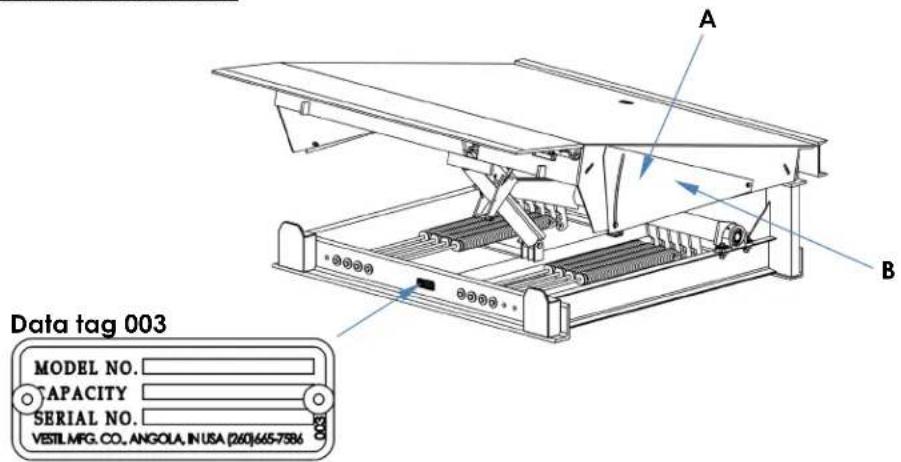
A: Label 288 (on both guards)
B: Label 367 (on both guards)
Vestil Manufacturing Corporation ("Vestil") warrants this product to be free of defects in material and workmanship during the warranty period. Our warranty obligation is to provide a replacement for a defective, original part covered by the warranty after we receive a proper request from the Warrantee (you) for warranty service.
Who may request service?
Only a warrantee may request service. You are a warrantee if you purchased the product from Vestil or from an authorized distributor AND Vestil has been fully paid.
Definition of "original part"?
An original part is a part used to make the product as shipped to the Warrantee.
What is a "proper request"?
A request for warranty service is proper if Vestil receives: 1) a photocopy of the Customer Invoice that displays the shipping date; AND 2) a written request for warranty service including your name and phone number. Send requests by one of the following methods:
US Mail
Vestil Manufacturing Corporation
2999 North Wayne Street, PO Box 507
Angola, IN 46703
Fax
(260) 665-1339
Phone
(260) 665-7586
info@vestil.com
Enter "Warranty service
request" in subject field.
In the written request, list the parts believed to be defective and include the address where replacements should be delivered. After Vestil receives your request for warranty service, an authorized representative will contact you to determine whether your claim is covered by the warranty. Before providing warranty service, Vestil will require you to send the entire product, or just the defective part (or parts), to its facility in Angola, IN.
What is covered under the warranty?
The warranty covers defects in the following original, dynamic parts: motors, hydraulic pumps, motor controllers, and cylinders. It also covers defects in original parts that wear under normal usage conditions ("wearing parts"), such as bearings, hoses, wheels, seals, brushes, and batteries.
How long is the warranty period?
The warranty period for original dynamic components is 1 year. For wearing parts, the warranty period is 90 days. Both warranty periods begin on the date Vestil ships the product to the Warrantee. If the product was purchased from an authorized distributor, the periods begin when the distributor ships the product. Vestil may, at its sole discretion, extend a warranty period for products shipped from authorized distributors by up to 30 days to account for shipping time.
If a defective part is covered by the warranty, what will Vestil do to correct the problem?
Vestil will provide an appropriate replacement for any covered part. An authorized representative of Vestil will contact you to discuss your claim.
What is not covered by the warranty?
The Warrantee (you) is responsible for paying labor costs and freight costs to return the product to Vestil for warranty service.
Events that automatically void this Limited Warranty.
- Misuse;
- Negligent assembly, installation, operation or repair;
• Installation/use in corrosive environments; - Inadequate or improper maintenance;
• Damage sustained during shipping;
• Collisions or other accidents that damage the product; - Unauthorized modifications: Do not modify the product IN ANY WAY without first receiving written authorization from Vestil.
Do any other warranties apply to the product?
Vestil Manufacturing Corp. makes no other express warranties. All implied warranties are disclaimed to the extent allowed by law. Any implied warranty not disclaimed is limited in scope to the terms of this Limited Warranty. Vestil makes no warranty or representation that this product complies with any state or local design, performance, or safety code or standard. Noncompliance with any such code or standard is not a defect in material or workmanship.



- VESTIL MANUFACTURING CORP
- RR-SERIES DOCK LEVELERS
- RECEIVING INSTRUCTIONS
- TECHNICAL SERVICE & REPLACEMENT PARTS
- ELECTRONIC COPIES OF INSTRUCTION MANUALS
- SIGNAL WORDS
- SAFETY INSTRUCTIONS
- WARNING
- RR-65, RR-66, RR-68 AND RR-610 EXPLODED VIEW BILL OF MATERIALS ON FOLLOWING PAGE
- RR-75, RR-76, RR-78 AND RR-710 EXPLODED VIEW BILL OF MATERIALS ON FOLLOWING PAGE
- NOTICE
- OPERATING THE DOCK LEVELER
- BEFORE USE
- AFTER USE
- NOTICE IF THE TRUCK DEPARTS BEFORE THE DOCK LEVELER IS RETRACTED, THE LIP WILL FALL TO THE DOWN POSITION. THE LIP MIGHT NOT BE IN THE KEEPERS
- RECORD OF SATISFACTORY CONDITION
- INSPECTIONS & MAINTENANCE
- EVERY USE
- MONTHLY
- ADJUSTING SPRING TENSION
- DECK LIFTING MECHANISM
- LIP EXTENDING MECHANISM
- ADJUSTMENT SEQUENCE
- LABELING DIAGRAMS
- WHO MAY REQUEST SERVICE
- DEFINITION OF "ORIGINAL PART
- WHAT IS A "PROPER REQUEST
- US MAIL
- FAX
- WHAT IS COVERED UNDER THE WARRANTY
- HOW LONG IS THE WARRANTY PERIOD
- IF A DEFECTIVE PART IS COVERED BY THE WARRANTY, WHAT WILL VESTIL DO TO CORRECT THE PROBLEM
- WHAT IS NOT COVERED BY THE WARRANTY
- EVENTS THAT AUTOMATICALLY VOID THIS LIMITED WARRANTY
- DO ANY OTHER WARRANTIES APPLY TO THE PRODUCT
Brand : Vestil
Model : RR-68-50
Category : Niveauur de quai