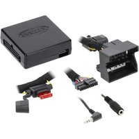
AXTC-MB3 - Interface de contrôle automobile Axxess - Free user manual and instructions
Find the device manual for free AXTC-MB3 Axxess in PDF.


| Product Type | Electronic Interface Module |
| Brand | Axxess |
| Model | AXTC-MB3 |
| Compatibility | Select vehicles (refer to vehicle fit guide) |
| Dimensions | 2.5 x 1.5 x 0.5 in (63.5 x 38.1 x 12.7 mm) |
| Weight | 0.2 lb (90 g) |
| Input Voltage | 12V DC (vehicle battery) |
| Operating Temperature | -40°F to 185°F (-40°C to 85°C) |
| Primary Functions | Vehicle integration, audio signal retention, chime preservation |
| Wiring Harness | Plug-and-play T-harness included |
| Installation | Professional installation recommended |
| Material | ABS plastic housing, copper wire |
| Certifications | CE, RoHS |
| Warranty | 1 year limited warranty |
| Manual Language | English (4 pages PDF) |
| Maintenance | Keep dry, avoid direct sunlight, no cleaning required |
| Safety | Disconnect battery before installation |
| Repairability | Non-repairable, replace if faulty |
Frequently Asked Questions - AXTC-MB3 Axxess
User questions about AXTC-MB3 Axxess
0 question about this device. Answer the ones you know or ask your own.
Ask a new question about this device
Download the instructions for your Interface de contrôle automobile in PDF format for free! Find your manual AXTC-MB3 - Axxess and take your electronic device back in hand. On this page are published all the documents necessary for the use of your device. AXTC-MB3 by Axxess.
USER MANUAL AXTC-MB3 Axxess
APPLICATIONS
Mercedes
C Class 2016-2021
ML/GL 2016-2021
Mercedes SWC (Steering Wheel Control) and Data Interface 2016-2021
INTERFACE FEATURES
- Designed for non-amplified models
- Provides accessory power (12 volt 10-amp)
- Provides wires for multimedia radios (park brake, reverse, speed sense)
- Retains audio controls on the steering wheel
- Designed to be compatible with all major radio brands
- Auto detects vehicle type, radio connection, and preset controls
- Ability to dual assign steering wheel control buttons
- Retains memory settings even after battery disconnection or interface removal (nonvolatile memory)
- Provides illumination output
- Micro-B USB updatable
INTERFACE COMPONENTS
- AXTC-MB3 Interface
• LD-SWXC-MB3 Harness
• 3.5mm Adapter
Product Info

TABLE OF CONTENTS
Connections: LD-SWCX-MB3 2
Programming......3
Troubleshooting....4
Connector View 4
Visit AxxessInterfaces.com for more detailed information
about the product and up-to-date vehicle specific applications.
TOOLS & INSTALLATION ACCESSORIES REQUIRED
• Crimping tool and connectors or
- Solder gun, solder, and heat shrink
- Tape
- Wire cutter
- Zip-ties
- Multimeter
ATTENTION: With the key out of the ignition, disconnect the negative battery terminal before installing this product. Ensure that all installation connections, especially the air bag indicator lights, are plugged in before reconnecting the battery or cycling the ignition to test this product.
NOTE: Refer also to the instructions included with the aftermarket accessory before installing this device.
CONNECTIONS: LD-SWCX-MB3 HARNESS

PROGRAMMING

Open the driver's door, and keep open during the programming process.

Cycle the ignition on.

Connect the AXTC-MB3 harness to the AXTC-MB3 Interface.

Locate the Volume Up button on the the steering wheel. Program the interface by tapping the Volume Up button until the LED stops flashing.
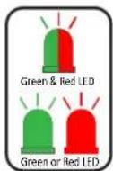
The LED light will flash Green & Red while the interface programs the radio to the steering wheel controls. Once programmed, the LED light will go out, then produce a pattern which will identify the radio type installed.

The LED light will go out, then once again quickly flash Green & Red while the interface programs itself to the vehicle. Once programmed, the LED light will go out again, then turn solid Green.

Cycle the ignition off, then back on.

Test all functions of the installation for proper operation.
TROUBLESHOOTING
1.2.

LED Light
Reset Button
If the interface fails to function, press and release the reset button, then repeat the programming process from step 5 to try again.
Final LED Feedback
At the end of programming the LED light will turn solid Green which indicates programming was successful. If the LED light didn't turn solid Green, reference the list below to understand which programming section the problem may stem from.
| LED Light | Radio Programming Section | Vehicle Programming Section |
| Solid Green | Pass | Pass |
| Slow Red Flash | Fail | Pass |
| Slow Green Flash | Pass | Fail |
| Solid Red | Fail | Fail |
Note: If the 3.5mm jack is not connected to the radio the LED feedback can still show Pass, as an open connection will be shown by the interface as an Alpine radio.
QR Code Scan Here

Further troubleshooting steps and information can be located at: axxessinterfaces.com
CONNECTOR VIEW
(4) corner wires only shown, just for reference
Pin-11 Yellow Pin-1 Yellow

Pin View of Connector
Pin-20 Blue/Pink (labeled on connector) Pin-10 Blue/Pink
Having difficulties? We're here to help.
Contact our Tech Support line at: 386-257-1187
Or via email at: techsupport@metra-autosound.com
Tech Support Hours (Eastern Standard Time)
Monday - Friday: 9:00 AM - 7:00 PM
Saturday: 10:00 AM - 5:00 PM
Sunday: 10:00 AM - 4:00 PM

KNOWLEDGE IS POWER
Enhance your installation and fabrication skills by enrolling in the most recognized and respected mobile electronics school in our industry. Log onto www.instellerinstitute.edu or call 386-672-5771 for more information and take steps toward a better tomorrow.

Metra recommends MECP certified technicians
- APPLICATIONS
- MERCEDES SWC (STEERING WHEEL CONTROL) AND DATA INTERFACE 2016-2021
- INTERFACE FEATURES
- INTERFACE COMPONENTS
- TABLE OF CONTENTS
- TOOLS & INSTALLATION ACCESSORIES REQUIRED
- PROGRAMMING
- TROUBLESHOOTING
- FINAL LED FEEDBACK
- CONNECTOR VIEW
- TECH SUPPORT HOURS (EASTERN STANDARD TIME)
- KNOWLEDGE IS POWER
- METRA RECOMMENDS MECP CERTIFIED TECHNICIANS
Brand : Axxess
Model : AXTC-MB3
Category : Interface de contrôle automobile