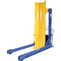
HDD-60-10-P-DC - Chariot élévateur hydraulique Vestil - Free user manual and instructions
Find the device manual for free HDD-60-10-P-DC Vestil in PDF.


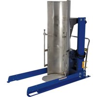
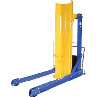
| Product Type | Hydraulic Drum Dumper |
| Model | HDD-60-10-P-DC |
| Brand | Vestil |
| Capacity | 1000 lbs (454 kg) |
| Drum Size Compatibility | 55-gallon steel or plastic drums |
| Power Source | 12V DC battery (integrated) |
| Lift Mechanism | Hydraulic pump with manual backup |
| Overall Dimensions (H x W x L) | 48 x 36 x 48 inches (122 x 91 x 122 cm) |
| Weight | 350 lbs (159 kg) |
| Frame Material | Heavy-duty steel with powder coat finish |
| Wheels | Two fixed and two swivel casters with brakes |
| Dumping Angle | Up to 135 degrees |
| Control Type | Push button pendant with 10 ft cord |
| Safety Features | Emergency stop button, drum locking clamp, overload relief valve |
| Maintenance | Check hydraulic fluid level monthly; lubricate pivot points every 3 months |
| Cleaning Instructions | Wipe with damp cloth; do not use abrasive cleaners |
| Spare Parts Availability | Replaceable hydraulic pump, motor, battery, and caster assemblies |
| Warranty | 1 year limited warranty |
| Compliance | ANSI/ASME B30.20, OSHA standards |
Frequently Asked Questions - HDD-60-10-P-DC Vestil
User questions about HDD-60-10-P-DC Vestil
0 question about this device. Answer the ones you know or ask your own.
Ask a new question about this device
Download the instructions for your Chariot élévateur hydraulique in PDF format for free! Find your manual HDD-60-10-P-DC - Vestil and take your electronic device back in hand. On this page are published all the documents necessary for the use of your device. HDD-60-10-P-DC by Vestil.
USER MANUAL HDD-60-10-P-DC Vestil
Vestil Manufacturing Corp.
2999 North Wayne Street, P.O. Box 507, Angola, IN 46703
Telephone: (260) 665-7586 -or- Toll Free (800) 348-0868
Fax: (260) 665-1339
Web: www.vestilmfg.com e-mail: info@vestil.com
HDD-Series Hydraulic Drum Dumpers
Instruction Manual

Receiving Instructions
After delivery, remove the packaging from the product. Inspect the product closely to determine whether it sustained damage during transport. If damage is discovered, record a complete description of it on the bill of lading. If the product is undamaged, discard the packaging.
NOTE: The end-user is solely responsible for confirming that product design, use, and maintenance comply with laws, regulations, codes, and mandatory standards applied where the product is used.
Technical Service & Replacement Parts
For answers to questions not addressed in these instructions and to order replacement parts, labels, and accessories, call our Technical Service and Parts Department at (260) 665-7586. The department can also be contacted online at http://www.vestilmfg.com/parts_info.htm.
Electronic copies of Instruction Manuals
Additional copies of this instruction manual may be downloaded from https://www.vestil.com/page-manuals.php.
Table of Contents
| Specifications | 2 - 3 |
| Signal Words | 4 |
| Safety Instructions | 4 |
| Applying Floor Locks | 4 |
| Installation | 11 |
| Loading the Dumper | 11 |
| Record of Satisfactory Condition | 11 |
| Inspections | 11 - 12 |
| *Power Unit Operation | 12 - 13 |
| Troubleshooting | 23 |
| Labeling Diagram | 24 |
| Limited Warranty | 25 |
Table of Figures
| FIG. 1: HDD-36-S exploded view | 5 |
| FIG. 2: HDD-48-S exploded view | 5 |
| FIG. 3: HDD-60-S exploded view | 6 |
| FIG. 4: HDD-72-S exploded view | 6 |
| FIG. 5: HDD-36-P exploded view | 7 |
| FIG. 6: HDD-48-P exploded view | 8 |
| FIG. 7: HDD-60-P exploded view | 9 |
| FIG. 8: HDD-72-S exploded view | 10 |
| FIG. 9: Hydraulic Circuit Diagram | 13 |
| *FIGS. 10A-10F: Electrical Circuit Diagrams | 14 - 19 |
| *FIG. 11: Motor Lead Diagrams & Transformer Diagram | 20 |
| *FIGS. 12A-12B: Modular Power Unit Parts Diagram | 21 - 22 |
*NOTE: Figures 10A – 12B are views of the modular power unit. These diagrams only apply to units manufactured before 12-01-2018. Units manufactured on or after 12-01-2018 receive a redesigned modular power unit (MPU GEN2). Diagrams and operating instructions for GEN2 power units are provided in separate MPU-AC/DC manuals.*
Specifications:
Dimensions and other product attributes appear in the diagrams and table below:
Stationary (bolt-down) HDD models

| Model A | B | C | D | E | F | Capacity | Net weight | |||||
| HDD-36-7-S | 36" | 9 | 3/4" | 14" | 60" | 95 | 3/4" | 611/2 | 750 lb. | 709 lb. | ||
| HDD-36-10-S | 36" | 93/4" | 14" | 60" | 95 | 3/4" | 611/2 | 1,000 lb. | 727 lb. | |||
| HDD-36-15-S | 36" | 93/4" | 14" | 60" | 95 | 3/4" | 611/2 | 1,500 lb. | 786 lb. | |||
| HDD-48-7-S | 48" | 93/4" | 14" | 72" | 116" | 71 | 1/2 | 750 lb. | 800 lb. | |||
| HDD-48-10-S | 48" | 93/4" | 14" | 72" | 116" | 71 | 1/2 | 1,000 lb. | 792 lb. | |||
| HDD-48-15-S | 48" | 93/4" | 14" | 72" | 116" | 71 | 1/2 | 1,500 lb. | 814 lb. | |||
| HDD-60-7-S | 60" | 93/4" | 14" | 84" | 136 | 3/4" | 80" | 750 lb. | 988 lb. | |||
| HDD-60-10-S | 60" | 93/4" | 14" | 84" | 136 | 3/4" | 80" | 1,000 lb. | 942 lb. | |||
| HDD-60-15-S | 60" | 93/4" | 14" | 84" | 136 | 3/4" | 80" | 1,500 lb. | 937 lb. | |||
| HDD-72-7-S | 72" | 91/2" | 131/2" | 951/4" | 1571/4" | 92" | 750 lb. | 1,113 lb. | ||||
| HDD-72-10-S | 72" | 91/2" | 131/2" | 951/4" | 1571/4" | 92" | 1,000 lb. | 1,055 lb. | ||||
| HDD-72-15-S | 72" | 91/2" | 131/2" | 951/2" | 1571/4" | 92" | 1,500 lb. | 1,036 lb. |
Portable HDD models

| Model A B C D E F Capacity Net weight | ||||||||
| HDD-36-7-P 36" 9 | 3/4" 14" 63 | 3/4" 96" 61 | 1/2" 750 lb. | 788 lb. | ||||
| HDD-36-10-P 36" 9 | 3/4" 14" 63 | 3/4" 96" 61 | 1/2" 1,000 lb. | 763 lb. | ||||
| HDD-36-15-P | 36" 9 | 3/4" 14" 63 | 3/4" 96" 61 | 1/2" 1,500 lb. | 776 lb. | |||
| HDD-48-7-P | 48" 9 | 3/4" 14" 72 | 1/2" | 1163/4" | 711/2" 750 lb. | 864 lb. | ||
| HDD-48-10-P | 48" 9 | 3/4" 14" 72 | 1/2" | 1163/4" | 711/2" 1,000 lb. | 862 lb. | ||
| HDD-48-15-P | 48" 9 | 3/4" 14" 72 | 1/2" | 1163/4" | 711/2" 1,500 lb. | 880 lb. | ||
| HDD-60-7-P | 60" 9 | 3/4" 14" 84 | 1/2" | 1371/4" | 80" | 750 lb. | 1,019 lb. | |
| HDD-60-10-P | 60" 9 | 3/4" 14" 84 | 1/2" | 1371/4" | 80" 1,000 lb. | 1,042 lb. | ||
| HDD-60-15-P | 60" 9 | 3/4" 14" 84 | 1/2" | 1371/4" | 80" 1,500 lb. | 1,026 lb. | ||
| HDD-72-7-P | 72" 9 | 1/4" 13 1/2" | 96" 157 1/2" | 92" | 750 lb. | 1,034 lb. | ||
| HDD-72-10-P | 72" 9 | 1/4" 13 1/2" | 96" 157 1/2" | 92" 1,000 lb. | 1,100 lb. | |||
| HDD-72-15-P | 72" 9 | 1/4" 13 1/2" | 96" 157 1/2" | 92" 1,500 lb. | 1,115 lb. | |||
SIGNAL WORDS
This manual uses SIGNAL WORDS to draw attention to uses of the product that could result in personal injuries, as well as the probable seriousness of those injuries. Other signal words call attention to uses likely to cause property damage. Signal words used in this manual appear below along with the definition of each word.

Identifies a hazardous situation which, if not avoided, WILL result in DEATH or SERIOUS INJURY. Use of this signal word is limited to the most extreme situations.

Identifies a hazardous situation which, if not avoided, COULD result in DEATH or SERIOUS INJURY.

Indicates a hazardous situation which, if not avoided, COULD result in MINOR or MODERATE injury.

Identifies practices likely to result in product/property damage, such as operation that might damage the product.
SAFETY INSTRUCTIONS
We strive to identify all hazards associated with the use of our products. However, material handling is dangerous and no manual can address every risk. The most effective way to avoid injury is for the end-user to exercise sound judgment whenever using this product.
WARNING
Improper or careless operation of this drum dumper might result in serious personal injuries.
- Failure to read and understand the entire manual before assembling, using or servicing the product constitutes misuse. Read the manual whenever necessary to refresh your understanding of proper use and maintenance procedures.
- ONLY use the dumper as a means for emptying drums. ALWAYS properly load the dumper according to the directions in Loading the Dumper on p. 11.
- DO NOT use a damaged dumper. Inspect the dumper according to the Inspection instructions on p. 11-12. DO NOT continue to use the dumper unless it is in Satisfactory Condition.
- DO NOT stand beneath or travel under the dumper chute while it is elevated.
- DO NOT load or operate the chute of a portable dumper unless both floor locks (part no. 08-025-008 in figures 5, 6, 7, and 8 on pages 7, 8, 9, and 10) solidly contact the floor. Floor locks are located on either side of the handle. Wind the locks through the threaded receivers in the frame until they solidly contact the ground.
- DO NOT use this dumper UNLESS every label shown in the Labeling Diagram on p. 24 is in place, undamaged, and easily readable.
- DO NOT exceed the capacity of the dumper. The capacity of each model appears in the tables on pp. 2-3 as well as on label 287. See Labeling diagram on p. 24. The weight of the container to be dumped plus the weight of its contents must not exceed the capacity.
- DO NOT modify the dumper in any way UNLESS you first obtain written approval from Vestil. Modifying the dumper without first receiving approval automatically voids the Limited Warranty and might make the dumper unsafe to use.
NOTICE
DO NOT fill the hydraulic system with brake fluid or jack oils. Only fill the hydraulic system with either anti-wear hydraulic oil, viscosity grade 150 SUS at 100° F (ISO 32cSt at 40° C) or Dexron transmission fluid.
APPLYING FLOOR LOCKS (HDD-##-#-P units only)
A floor lock is provided on both sides of the handle. In Figures 5, 6, 7, and 8 on pages 7, 8, 9, and 10, floor locks are identified as part no. 08-025-008. Once the dumper is in the necessary position and before loading the chute with a drum, wind the floor locks through the threaded receivers (welded to the frame) until they solidly contact the floor. Do not turn the locks so far that the casters are noticeably lifted off of the floor because the dumper might become unstable if 1 or more casters are lifted off of the floor. It is only necessary for the locks to press against the floor. Try to push the dumper to confirm that the locks are engaged. The dumper should resist movement although all 4 casters remain in contact with the floor.
FIG. 1: HDD-36-S series stationary dumpers exploded view and bill of materials

| Item | Part no. | Description | Qty. | Item | Part no. | Description | Qty. |
| 1 | 99-002-122 | Final assembly without power unit | 1 | 9 | 36102 | Hex nut, grade A, zinc-plated, 1/4 " - 20 | 1 |
| 2 | 09-514-131 | Weldment, frame, stationary | 1 | 10 | 22805 | Elevator bolt, limit switch | 1 |
| 3 | 09-512-001 | Hinge block assembly | 2 | 11 | 09-545-028 | Weldment, subassembly, chute | 1 |
| 4 | 09-537-013 | Assembly, drum clamp, casting | 2 | 12 | 12365 | 3/4 " – 10UNC x 3" zinc-plated #5 bolt | 4 |
| 5 | 37039 Nylock nut, zinc-plated, 3/4 " – 10 4 | 13 | 99-021-909-001 | Hydraulic cylinder, 21/2 " x 18" 1 | |||
| 6 | 24-612-003 | Pin assembly, cylinder | 1 | 14 | 99-160-097 | Modular power unit, GEN2 (display only) | 1 |
| 7 | 09-145-020 | Threaded pipe cap | 2 | 15 | 31802 | Screw, self-tapping screw | 2 |
| 8 | 01-022-021 | Switch, limit, roller arm | 1 |
FIG. 2: HDD-48-S series stationary dumpers exploded view and bill of materials
| Item | Part no. | Description | Qty. |
| 1 9 | 9-002-123 | Final assembly without power unit | 1 |
| 2 | 09-514-129 | Weldment, frame, stationary | 1 |
| 3 | 09-512-001 | Hinge block assembly | 2 |
| 4 0 | 9-537-013 | Assembly, drum clamp, casting | 2 |
| 5 3 | 7039 | Nylock nut, zinc-plated, 3/4 " - 10 | 4 |
| 6 | 24-612-003 | Pin assembly, cylinder | 1 |
| 7 | 09-145-020 | Threaded pipe cap | 2 |
| 8 | 01-022-021 | Switch, limit, roller arm | 1 |
| 9 3 | 6102 | Hex nut, grade A, zinc-plated, 1/4 " - 20 | 1 |
| 10 | 22805 | Elevator bolt, limit switch | 1 |
| 11 0 | 9-545-030 | Weldment, subassembly, chute | 1 |
| 12 1 | 3365 | 3/4 " - 10UNC x 3" zinc-plated #5 bolt | 4 |
| 13 | 99-021-909-001 | Hydraulic cylinder, 21/2 " x 18" | 1 |
| 14 9 | 99-160-097 | Modular power unit, GEN2 (display only) | 1 |
| 15 | 31802 | Screw, self-tapping screw | 2 |

FIG. 3: HDD-60-S series stationary dumpers exploded view and bill of materials

| Item | Part no. | Description Qty. | |
| 1 | 99-002-124 | Final assembly without power unit | 1 |
| 1.1 | 09-514-127 | Weldment, frame, stationary | 1 |
| 1.2 | 09-512-001 | Hinge block assembly 2 | |
| 1.3 | 09-537-013 | Assembly, drum clamp, casting | 2 |
| 1.4 | 37039 | Nylock nut, zinc-plated, 3/4 " - 10 | 4 |
| 1.5 | 24-612-003 | Pin assembly, cylinder 1 | |
| 1.6 | 09-145-020 | Threaded pipe cap 2 | |
| 1.7 | 01-022-021 | Switch, limit, roller arm 1 | |
| 1.8 | 36102 | Hex nut, grade A, zinc-plated, 1/4 " - 20 | 1 |
| 1.9 | 22805 | Elevator bolt, limit switch 1 | |
| 1.10 | 09-545-031 | Weldment, subassembly, chute | 1 |
| 1.11 | 13365 | 3/4 " - 10UNC x 3" zinc-plated #5 bolt | 4 |
| 1.12 | 99-021-909-001 | Hydraulic cylinder, 21/2 " x 18" | 1 |
| 2 | 99-160-097 | Modular power unit, GEN2 (display only) | 1 |
| 3 | 31802 | Screw, self-tapping screw | 2 |
FIG. 4: HDD-72-S series stationary dumpers exploded view and bill of materials

| Item | Part no. | Description | Qty. |
| 1 9 | 9-002-125 | Final assembly without power unit | 1 |
| 1.1 | 09-514-125 | Weldment, frame, stationary | 1 |
| 1.2 | 09-512-001 Hinge block assembly | 2 | |
| 1.3 | 09-537-013 | Assembly, drum clamp, casting | 2 |
| 1.4 | 37039 | Nylock nut, zinc-plated, 3/4 " - 10 | 4 |
| 1.5 | 24-612-003 | Pin assembly, cylinder | 1 |
| 1.6 | 09-145-020 Threaded pipe cap 2 | ||
| 1.7 | 01-022-021 | Switch, limit, roller arm | 1 |
| 1.8 | 22805 Elevator bolt, limit switch 1 | ||
| 1.9 | 09-545-031 | Weldment, subassembly, chute | 1 |
| 1.10 | 13365 | 3/4 " - 10UNC x 3" zinc-plated #5 bolt | 4 |
| 1.11 | 36102 | Hex nut, grade A, zinc-plated, 1/4 " - 20 | 1 |
| 1.12 | 99-021-909-001 | Hydraulic cylinder, 21/2 " x 18" | 1 |
| 2 9 | 99-160-097 | Modular power unit, GEN2 (display only) | 1 |
| 3 | 31802 | Screw, self-tapping screw | 2 |
FIG. 5: HDD-36-P series portable dumpers exploded view and bill of materials

| Item | Part no. | Description | Qty. | Item | Part no. | Description | Qty. |
| 1 | 09-002-126 | Final assembly without power unit | 1 | 15 | 16-132-216 | Caster, 8", glass filled nylon | 2 |
| 2 | 09-514-131 | Weldment, frame, stationary | 1 | 16 | 09-525-009 | Weldment, handle bracket, right | 1 |
| 3 | 09-512-001 | Hinge block assembly | 2 | 17 | 16-025-028 | Handle, push handles, chromed | 1 |
| 4 | 09-537-013 | Assembly, drum clamp, casting | 2 | 18 | 09-525-008 | Weldment, handle bracket, left | 1 |
| 5 | 37039 | Nylock nut, zinc-plated, 3/4 " – 10 | 4 | 19 | 11055 | 5/16 "–18 x 1" HHCS #2 zinc-plated bolt | 2 |
| 6 | 24-612-003 | Pin assembly, cylinder | 1 | 20 | 36104 | 5/16 "–18 grade A zinc-plated hex nut | 2 |
| 7 | 09-145-020 | Threaded pipe cap | 2 | 21 | 09-016-169 | Bracket, wheel | 2 |
| 8 | 01-022-021 | Switch, limit, roller arm | 1 | 22 | 33012 | 1/2 " flat washer, low carbon, zinc finish | 20 |
| 9 | 36102 | Hex nut, grade A, zinc-plated, 1/4 " - 20 | 1 | 23 | 37030 | Nylock nut, zinc-plated, 1/2 " – 13 | 10 |
| 10 | 22805 | Elevator bolt, limit switch | 1 | 24 | 11219 | 1/2 "–13 x 4" hex head bolt | 10 |
| 11 | 09-545-028 | Weldment, subassembly, chute | 1 | 25 | 16-111-003 | Sleeve bearing for 2" wheel | 8 |
| 12 | 08-025-008 | 4-handle bolt, 4" | 2 | 26 | 99-612-001 | 3/8 "–16 x 5" bolt and nut combo. | 2 |
| 13 | 12365 | 3/4 " – 10 x 3" HHCS #5 plain bolt 4 27 | 99-021-909-001 | Hydraulic cylinder, 21/2 " x 18" 1 | |||
| 14 | 16-132-262 | 6" x 2" glass filled nylon swivel caster | 2 | 28 | 99-160-097 | Modular power unit, GEN2 (display only) | 1 |
| 29 | 31802 | Screw, self-tapping screw | 2 |
FIG. 6: HDD-48-P series portable dumpers exploded view and bill of materials

| Item | Part no. | Description | Qty. | Item | Part no. | Description | Qty. |
| 1 | 09-002-127 | Final assembly without power unit | 1 | 15 | 13365 | 3/4" - 10 × 3" HHCS #5 plain bolt | 4 |
| 2 | 09-514-129 | Weldment, frame, stationary | 1 | 16 | 09-525-008 | Weldment, handle bracket, left | 1 |
| 3 | 09-512-001 | Hinge block assembly | 2 | 17 | 09-525-009 | Weldment, handle bracket, right | 1 |
| 4 | 99-021-909-001 | Hydraulic cylinder, 21/2" × 18" 1 18 16-025-028 | Handle, push handles, chromed 1 | ||||
| 5 | 09-537-013 | Assembly, drum clamp, casting | 2 | 19 | 16-132-216 | Caster, 8", glass filled nylon | 2 |
| 6 | 37039 | Nylock nut, zinc-plated, 3/4" - 10 | 4 | 20 | 16-132-262 | 6" x 2" glass filled nylon swivel caster | 2 |
| 7 | 24-612-003 | Pin assembly, cylinder | 1 | 21 | 11055 | 5/16" - 18 × 1" HHCS #2 zinc-plated bolt | 2 |
| 8 | 09-145-020 | Threaded pipe cap | 2 | 22 | 36104 | 5/16" - 18 grade A zinc-plated hex nut | 2 |
| 9 | 01-022-021 | Switch, limit, roller arm | 1 | 23 | 09-016-169 | Bracket, wheel | 2 |
| 10 | 36102 | Hex nut, grade A, zinc-plated, 1/4" - 20 | 1 | 24 | 11219 | 1/2" - 13 × 4" hex head bolt | 10 |
| 11 | 22805 | Elevator bolt, limit switch | 1 | 25 | 16-111-003 | Sleeve bearing for 2" wheel | 8 |
| 12 | 09-545-030 | Weldment, subassembly, chute | 1 | 26 | 33012 | 1/2" flat washer, low carbon, zinc finish | 20 |
| 13 | 08-025-008 | 4-handle bolt, 4" | 2 | 27 | 99-612-001 | 3/8" - 16 × 5" bolt and nut combo. | 2 |
| 14 | 37030 Nylock nut, zinc-plated, 1/2" - 13 10 28 | 99-160-097 | Modular power unit, GEN2 (display only) | 1 | |||
| 29 | 31802 | Screw, self-tapping screw | 2 | ||||
FIG. 7: HDD-60-P series portable dumpers exploded view and bill of materials

| Item | Part no. | Description | Qty. | Item | Part no. | Description | Qty. |
| 1 | 09-002-128 | Final assembly without power unit | 1 | 1.14 | 09-525-008 | Weldment, handle bracket, left | 1 |
| 1.1 | 09-514-127 | Weldment, frame, stationary | 1 | 1.15 | 09-525-009 | Weldment, handle bracket, right | 1 |
| 1.2 | 09-512-001 | Hinge block assembly | 2 | 1.16 | 16-025-028 | Handle, push handles, chromed | 1 |
| 1.3 | 99-021-909-001 | Hydraulic cylinder, 21/2 " x 18" 1 1.17 | 16-13 | 2-262 | 6" x 2" glass filled nylon swivel caster | 2 | |
| 1.4 | 09-537-013 | Assembly, drum clamp, casting | 2 | 1.18 | 11055 | 1/4 “-20 x 1” HHCS #2 zinc-plated bolt | 2 |
| 1.5 | 37039 | Nylock nut, zinc-plated, 3/4 “ - 10 | 4 | 1.19 | 36104 | 5/16 “-18 grade A zinc-plated hex nut | 2 |
| 1.6 | 24-612-003 | Pin assembly, cylinder | 1 | 1.20 | 16-132-216 | Caster, 8", glass filled nylon | 2 |
| 1.7 | 09-145-020 | Threaded pipe cap | 2 | 1.21 | 09-016-169 | Bracket, wheel | 2 |
| 1.8 | 01-022-021 | Switch, limit, roller arm | 1 | 1.22 | 16-111-003 | Sleeve bearing for 2" wheel | 8 |
| 1.9 | 36102 Hex nut, | grade A, zinc-plated, 1/4 " - 20 | 1 1.23 | 33012 | 1/2 flat washer, low carbon, zinc finish | 20 | |
| 1.10 | 22805 | Elevator bolt, limit switch | 1 | 1.24 | 37030 | Nylock nut, zinc-plated, 1/2 " - 13 | 10 |
| 1.11 | 09-545-031 | Weldment, subassembly, chute | 1 | 1.25 | 11219 | 1/2 “-13 x 4" hex head bolt | 10 |
| 1.12 | 08-025-008 | 4-handle bolt, 4" | 2 | 1.26 | 99-612-001 | 3/8 “-16 x 5" bolt and nut combo. | 2 |
| 1.13 | 13365 | 3/4 " - 10 x 3" HHCS #5 plain bolt | 4 | 2 | 99-160-097 | Modular power unit, GEN2 (display only) | 1 |
| 3 | 31802 | Screw, self-tapping screw | 2 |
FIG. 8: HDD-72-P series portable dumpers exploded view and bill of materials

| Item | Part no. | Description | Qty. | Item | Part no. | Description | Qty. |
| 1 | 09-002-129 | Final assembly without power unit | 1 | 1.14 | 11055 | 1/4 “-20 x 1” HHCS #2 zinc-plated bolt | 2 |
| 1.1 | 09-514-125 | Weldment, frame, stationary | 1 | 1.15 | 16-025-028 | Handle, push handles, chromed | 1 |
| 1.2 | 09-512-001 | Hinge block assembly | 2 | 1.16 | 16-132-262 | 6" x 2" glass filled nylon swivel caster | 2 |
| 1.3 | 09-537-013 | Assembly, drum clamp, casting | 2 | 1.17 | 36104 | 5/16 “-18 grade A zinc-plated hex nut | 2 |
| 1.4 | 37039 | Nylock nut, zinc-plated, 3/4 ” - 10 | 4 | 1.18 | 36102 | Hex nut, grade A, zinc-plated, 1/4 ” - 20 | 1 |
| 1.5 | 24-612-003 | Pin assembly, cylinder | 1 | 1.19 | 16-132-216 | Caster, 8", glass filled nylon | 2 |
| 1.6 | 09-145-020 | Threaded pipe cap | 2 | 1.20 | 09-016-169 | Bracket, wheel | 2 |
| 1.7 | 01-022-021 | Switch, limit, roller arm | 1 | 1.21 | 16-111-003 | Sleeve bearing for 2" wheel | 8 |
| 1.8 | 22805 | Elevator bolt, limit switch | 1 | 1.22 | 33012 | 1/2 " flat washer, low carbon, zinc finish | 20 |
| 1.9 | 09-545-032 | Weldment, subassembly, chute | 1 | 1.23 | 11219 | 1/2 “-13 x 4" hex head bolt | 10 |
| 1.10 | 08-025-008 | 4-handle bolt, 4" | 2 | 1.24 | 37030 | Nylock nut, zinc-plated, 1/2 ” - 13 | 10 |
| 1.11 | 13365 | 3/4 ” - 10 x 3" HHCS #5 plain bolt | 4 | 1.25 | 99-612-001 | 3/8 “-16 x 5" bolt and nut combo. | 2 |
| 1.12 | 09-525-008 Weldment, handle bracket, left 1 1.26 | 99-021-909-001 | Hydraulic cylinder, 21/2 " x 18" 1 | ||||
| 1.13 | 09-525-009 Weldment, handle bracket, right 1 2 99-160-097 | Modular power unit, GEN2 (display only) | 1 | ||||
| 3 | 31802 | Screw, self-tapping screw | 2 | ||||
INSTALLATION (STATIONARY UNITS)
Step 1: Position the dumper where desired with a forklift.
Step 2: Drill holes approximately 4in. (10cm) deep.
Step 3: Secure the dumper to the floor by inserting 3/4 " anchor bolts through the bolt holes in the base frame.
Step 4: Shim and/or grout the sides of the frame as necessary to achieve levelness.
Step 5: (AC powered units) Connect the power cord to the power supply.

LOADING THE DUMPER: Before loading the dumper, apply the floor locks. See APPLYING FLOOR LOCKS on p. 4.
- Load a drum onto the chute: HDD-series dumpers are designed to accept 33 gallon and 55 gallon steel, plastic, and fiber drums. Place the drum on the base plate of the chute. The drum should rest against the chute wall.
- Apply the drum retainers (see diagrams in "Inspections" below): to prevent the drum from sliding out of the chute, move the retainers up or down the rails as necessary and into solid contact with the top of the drum. To move the retainers, press the rail clamps down. The hooked end of each retainer must contact the inside wall of the drum.
- Dump the drum: press the white (raise) button on the pendant controller to raise the chute to the dumping position. In response to the input from the controller, the piston extends and raises the bottom end of the chute. The piston extends only while the operator presses the white button. When the button is released, the cylinder stops extending and the chute stops moving. The chute maintains position when the button is released.
NOTE: If the net weight of the drum and its contents exceeds the capacity of the dumper, a relief valve in the hydraulic circuit opens. The cylinder cannot extend and consequently the chute will not move.
- Return the chute to the loading position: press the black (lower) button on the controller to retract the piston. As the piston retracts, it pulls the bottom end of the chute towards the ground. If the DOWN button is released before the chute is completely lowered, the chute will maintain its position.
RECORD OF SATISFACTORY CONDITION
Before putting the unit into service, make a record of its condition. Thoroughly photograph the unit from multiple angles. Include close range photographs of the drum retainers, pivot points, labeling, the chute, frame elements, and casters and wheels (mobile units) or anchoring sites (stationary units). Use the pendant controller to raise and lower the chute. Describe the motion of the chute, e.g. smooth and at a constant rate, as well as sounds produced by the power unit and the frame. Remove the cover of the power unit and photograph the internal components.
Collate all photographs and writings into a single file. Identify the file appropriately. This file is a record of the unit in satisfactory condition. Compare the results of all inspections to this record to determine whether the unit is in satisfactory condition. Do not use the dumper unless it is in satisfactory condition. Purely cosmetic changes, like damaged paint/powdercoat, do not constitute changes from satisfactory condition. However, touchup paint should be applied to all affected areas as soon as damage occurs to prevent rusting and/or corrosion from occurring.
INSPECTIONS: Compare results to the Record.
Refer to the appropriate FIG. 1, 2, 3, 4, 5, 6, 7, or 8 on p 5-10. Before each use, inspect the listed components:
- Modular power unit, pendant controller, and wiring: examine all wires for frays, cuts, tears, etc. (DC-powered units) Check battery charge status. Cycle the chute all the way up and all the way down. Recharge the battery, if necessary.
- Hydraulic system: check the reservoir and all hoses for pinches, kinks, punctures, and leaks.
- Drum retainers and clamp rails: examine the retainers for damage including bends, cracks, and looseness. Each clamp should maintain position along the rail (i.e. should not slide).
- Frame: check the hinge blocks, pivot shafts, cylinder brackets (at each end of cylinder at attachment points to the frame and the chute), legs, vertical frame, and chute for cracks, damaged welds, severe wear, and corrosion.
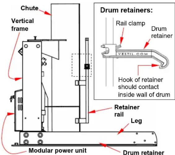
- Cylinder and limit switches: verify normal function. Cycle the chute through a complete dumping sequence (fully rotated and back to the ground). When the chute reaches dumping height, the power unit should stop running. The piston should extend and retract smoothly without binding or jerking. Listen for unusual sounds that might indicate binding or grinding during operation and watch for unusual movement. If you observe any unusual sound or movement, do not use the dumper until it has been restored to normal operating condition.
At least once per month, inspect the dumper as follows:
- Oil level: remove the cover from the modular power unit. Then, fully raise the chute (to the 45° “dumping position”) and observe the level of oil in the reservoir. The surface of the oil should be 1 to 11/2 inches below the fill hole. If oil is needed, add oil as specified below in Oil specifications.
- Pivot points: check the dumper for excessive wear. Pay particular attention to pivot points between hydraulic cylinders and cylinder brackets, and between pivot shafts and hinge blocks.
- Floor connection points: anchor bolts should prevent the frame from lifting off of the ground during chute operation. Concrete around each anchor bolt should be intact, i.e. not cracked or chipped.
- Fasteners: check each fastener connection (nuts, bolts, pins, etc.). Tighten loose connections. Replace all damaged hardware.
- Hydraulic hoses and electrical wires: check each wire and hose for damage (frays, kinks etc.).
6.Labels: labels should be easily readable, undamaged, and be affixed to the dumper as shown in the Labeling diagram on p. 23.
Oil specifications: Change the hydraulic oil at least once per year. Change the oil as soon as it becomes gritty or looks milky which indicates that water is present. Lower the chute, drain the oil, and replace it with either Dexron transmission fluid or anti-wear hydraulic oil viscosity grade 150 SUS at 100° F (ISO 32 cSt at 40° C.
POWER UNIT OPERATION: If your unit was manufactured on or after Dec. 1, 2018, see the NOTE in the Table of Contents on the cover page.
The drum dumper is powered by an electric motor directly coupled to a gear pump. The pump pressurizes the hydraulic fluid. Fluid pressure causes the piston of the hydraulic cylinder to extend. Piston extension causes the bottom of the chute to rotate until it is elevated above the top of the chute. A hydraulic manifold bolted directly onto the gear pump houses the hydraulic control components. Each component is rated for 3,000 psi working pressure. Important components of the power unit include:
- Electric motor: the motor is either AC powered (wall socket) or DC powered (battery). AC-powered motors can be wired for either single-phase or three-phase operation. Regardless of phase configuration, every motor is dual-voltage capable.
- Gear pump: the pump shaft is directly coupled to the shaft of the electric motor. Several displacements are available to match the horsepower of the motor selected.
- Check valve: prevents backflow of fluid through the pump and to the reservoir. Because fluid can only flow in response to an electrical signal from the pendant controller, the chute can maintain any position between the raised and lowered configurations.
- Pressure relief valve: opens a path for fluid to flow back to the reservoir if fluid pressure exceeds 3,000psi.
- Lowering solenoid valve: electrically-operated cartridge valve with an integral screen to keep contaminants from entering the valve.
- Pressure compensated flow control spool: this feature regulates the flow of hydraulic oil from the cylinder back to the reservoir. It is located beneath the lowering valve. This component allows the table to lower at a predetermined constant rate regardless of the weight of the dumper and contents. Several sizes are available.
- Displacement style hydraulic cylinder: each cylinder includes a bleeder valve located at top end for removing air from the hydraulic system.
- Velocity fuse: a safety device installed in the hose port of each cylinder. If a hose is punctured while the unit is operating, the velocity fuse closes automatically. The chute is stationary until pressure is reapplied to the system.
- Hydraulic fluid: HO150 hydraulic fluid. To replenish the fluid, add anti-wear hydraulic fluid with a viscosity grade of 150 SUS at 100°F (ISO 32 @ 40°C ) like AW-32 or Dexron transmission fluid.
Sequence of operation:
Raise/tilt the chute by pressing the white (UP) button. In response, the motor turns and rotates the gear pump. As the pump rotates, oil is drawn from the reservoir, passes through the suction filter, and enters the pump.
- The gear pump propels oil through the check valve to the lift cylinder.
- Releasing the white button during operation immediately halts chute movement. Additionally, an electrical upper travel limit switch automatically turns off the motor when the chute reaches a 45° angle to the ground (horizontal).
Lower the chute by pressing the black (DOWN) button.
- Lowering valve opens which bypasses the check valve and allows oil in the cylinder to flow to the reservoir (through return hoses). Oil flow to the reservoir is regulated by the pressure compensated flow control valve. By regulating the volume of oil that can flow through the spool, the speed at which the chute lowers is kept constant.
- Releasing the DOWN button during operation causes all chute movement to stop. The chute will remain in the same position until you press either button on the pendant controller.
Cleaning lowering solenoid valve: If the chute slowly loses elevation without pressing the DOWN button, lower the chute completely. Then, remove, inspect, and clean the lowering cartridge valve in the following manner:
- Lower the chute completely. Turn off electrical power to the unit. If your dumper is AC powered, unplug the electrical cord from the wall socket. If your unit is battery powered, turn the power switch to the OFF position.
- Unload the dumper.
- Remove the nut that fastens the solenoid coil to the valve stem; then remove the coil and unscrew the valve from the manifold.
- Inspect the valve for blockage.
- Inspect O-rings and back-up washers for cuts, tears, etc.
- Submerge the valve in mineral spirits or kerosene.
- Use a thin tool, e.g. a small screwdriver, to push the poppet in and out several times from the bottom end of the valve. The valve should move freely, about 1/16" between the closed and open positions. If the poppet sticks, the valve stem might be bent. Replace the poppet if it doesn't free up after cleaning.
- Remove mineral oil from the valve with compressed air.
- Move the poppet in and out.
- Inspect the bottom of the valve cavity in the manifold for foreign matter.
- With the thin tool, press the middle of the flow control spool, which is located in the bottom of the cavity. It should move down and up smoothly.
- Reinstall the valve in the manifold and tighten it to 20 lb·ft of torque.
Bleeding air from hydraulic system: If the chute lowers extremely slowly or does not lower, air in the cylinders might be the culprit. Air in the hydraulic system causes the velocity fuse to close, which traps oil in the cylinder. To overcome this problem, air must be “bled” from the system.
- Completely lower the chute and unload it;
- Locate the bleeder valve located at the top of the cylinder (it looks like a grease zerk). Hold a rag over the valve and open it about a half turn with a 1/4" or 5/16" wrench. Oil and air will sputter from the valve. Jog the motor by pressing the white (UP) button for just a second. If air continues to escape from the bleeder valve, jog the motor several more times. Wait at least 5 seconds between successive jogs.
- Close the valve once air no longer is heard or seen bubbling out of the valve. At this point, just a clear stream of oil is seen flowing from the bleeder valve. Close the valve.
- Remove the cover from the modular power unit and check the oil level in the reservoir. If the surface of the oil is lower than 1 to 1 1/2 in. below the fill hole, then add oil until it is between 1 and 1 1/2 inches of the fill hole. Add only anti-wear hydraulic fluid with a viscosity grade of 150 SUS at 100° F (ISO 32 @ 40° C ) like AW-32 or Dexron transmission fluid.
![graph TD A["1"] --> B["2"] B --> C["3"] C --> D["4"] D --> E["5"] E --> F["6"] F --> G["7"] G --> H["8"] H --> I["9"] I --> J["01-127-010 mW C"] style A fill:#f9f,stroke:#333 style B fill:#ccf,stroke:#333 style C fill:#cfc,stroke:#333 style D fill:#fcc,stroke:#333 style E fill:#cff,stroke:#333 style…](/content/2026/07/1459913/images/e420dcd86edca185f4e7a9212e9fe4c2cc71caf547fbcea39deb81260d39854d.jpg)
| Item | Part no. | Description | Qty. |
| 1 01 | -127-010 | Manifold, aluminum, w/o valves | 1 |
| 2 01 | -135-052 | 2HP, 3-phase, 1725 RPM motor | 1 |
| 3 01 | -143-908 | Gear pump, 0.153 displacement | 1 |
| 4 99 | -021-909 | Cylinder, 21/2 " x 18" ram style | 2 |
| 5 99 | -153-006 | Relief valve, 210 bar, size 08 | 1 |
| 6 99 | -031-029 | Inlet screen, 100 mesh 2" pancake | 1 |
| 7 99 | -153-038 | Flow control, PC, 1/16 " - 20, 2gpm | 1 |
| 8 01 | -531-001 | Velocity fuse, adjustable, brass | 2 |
| 9 99 | -153-015 | Valve, cartridge, NC, no coil, w/ nut | 1 |
| 10 | 99-153-011 | Check valve, size 08 | 1 |
| 11 99 | -023-002 | Reservoir, L-shaped, 1.16 gal., 1.0 gal. nominal | 1 |
FIG. 10A: 115VAC, Electrical Circuit Diagram (09124017 Rev. D)
*Refer to MPU-GEN2 manual if your unit was manufactured on or after 12-01-2018.*
NOTE: In this diagram, all components are represented with the chute in "home" location, i.e. resting, lowered position.

FIG. 10B: 115VAC, Upper & Lower Limit Switches, Electrical Circuit Diagram (09124014 Rev. C)
*Refer to MPU-GEN2 manual if your unit was manufactured on or after 12-01-2018.*
NOTE: In this diagram, all components are represented with the chute in "home" location, i.e. resting, lowered position.
115VAC, 3 /4HP
12 FLA, 1725 RPM
NOTE: Overcurrent and short-circuit protection should be provided by the end user in accordance with recommendations and requirements in NEC (NFPA 70) and local codes.
![graph TD A["CONTROL RELAY BASE LAYOUT (TOP VIEW)"] --> B["8"] A --> C["12"] A --> D["4"] A --> E["3"] A --> F["7"] A --> G["11"] A --> H["10"] A --> I["2"] A --> J["6"] A --> K["1"] A --> L["5"] A --> M["9"] A --> N["13"] B --> O["14"] C --> P["14"] D --> Q["14"] E --> R["14"] F --> S["14"] G --> T[…](/content/2026/07/1459913/images/8dc65c5d769a241eead6f146ec13c8db1bc0d832c8c3068f76ebc1534929967c.jpg)
FIG. 10C: 208-230VAC, 1-phase, electrical circuit diagram (09124018 Rev. C) *Refer to MPU-GEN2 manual if your unit was manufactured on or after 12-01-2018.*
NOTE: In this diagram, all components are represented with the chute in "home" location, i.e. resting, lowered position.

NOTE: Overcurrent and short-circuit protection should be provided by the end user in accordance with recommendations and requirements in NEC (NFPA 70) and local codes.
![graph TD A["8"] --> B["4"] C["12"] --> D["11"] E["3"] --> F["7"] G["2"] --> H["6"] I["1"] --> J["5"] K["9"] --> L["10"] M["14"] --> N["13"] style A fill:#f9f,stroke:#333 style C fill:#f9f,stroke:#333 style E fill:#f9f,stroke:#333 style G fill:#f9f,stroke:#333 style I fill:#f9f,stroke:#333 style K fi…](/content/2026/07/1459913/images/caa61b4c061270bcf10033798c38e6d49dc582d1c0bc7a86c49821d8318cd862.jpg)
FIG. 10D: 208-230VAC, Upper & Lower Limit Switches, 1-phase electrical circuit diagram (09124015 Rev. C)
*Refer to MPU-GEN2 manual if your unit was manufactured on or after 12-01-2018.*
NOTE: In this diagram, all components are represented with the chute in "home" location, i.e. resting, lowered position.
---- Indicates wire and/or components end-user must provide
208-230VAC, 1.5 HP 12 FLA, 1725 RPM
NOTE: Overcurrent and short-circuit protection should be provided by the end user in accordance with recommendations and requirements in NEC (NFPA 70) and local codes.
![graph TD A["CONTROL RELAY BASE LAYOUT (TOP VIEW)"] --> B["8"] A --> C["12"] A --> D["4"] A --> E["3"] A --> F["7"] A --> G["11"] A --> H["10"] A --> I["14"] A --> J["13"] A --> K["2"] A --> L["6"] A --> M["1"] A --> N["5"] A --> O["9"]](/content/2026/07/1459913/images/4ecdb52c48a647fc9c6d641b80858c44fe2f4394d3b4a6c0b1f9f9245d7640c9.jpg)
FIG. 10E: 3-phase 208-230/460 VAC, electrical circuit diagram (09124019 Rev. C) *Refer to MPU-GEN2 manual if your unit was manufactured on or after 12-01-2018.*
NOTE: In this diagram, all components are represented with the chute in "home" location, i.e. resting, lowered position.

FIG. 10F: 3-phase 208-230/460 VAC, Upper & Lower Limit Switches, electrical circuit diagram (09124016 Rev. C)
*Refer to MPU-GEN2 manual if your unit was manufactured on or after 12-01-2018.*
NOTE: In this diagram, all components are represented with the chute in "home" location, i.e. resting, lowered position. —— Indicates wire and/or components end-user must provide 208-230/460 VAC, 2 HP 7.8-6.2/3.1 FLA, 1725 RPM -OR- 208-230/460 VAC, 2 HP 5.6/2.8 FLA, 3450RPM
NOTE: Overcurrent and short-circuit protection should be provided by the end user in accordance with recommendations and requirements in NEC (NFPA 70) and local codes.
![graph TD A["CONTROL RELAY BASE LAYOUT (TOP VIEW)"] --> B["8"] A --> C["12"] A --> D["4"] A --> E["3"] A --> F["7"] A --> G["11"] A --> H["10"] A --> I["14"] A --> J["13"] A --> K["2"] A --> L["6"] A --> M["1"] A --> N["5"] A --> O["9"]](/content/2026/07/1459913/images/c7400f4f7b865525e034a19f83a61a68188b631c8667532d67564ec66af8f0f6.jpg)
FIG. 11: Motor lead connection diagrams for all 0.5HP, 0.75HP, & 3hp single-phase motors and for all 2HP, 5.5HP, and 6.5HP three phase motors *Refer to MPU-GEN2 manual if your unit was manufactured on or after 12-01-2018.*


L1 L2

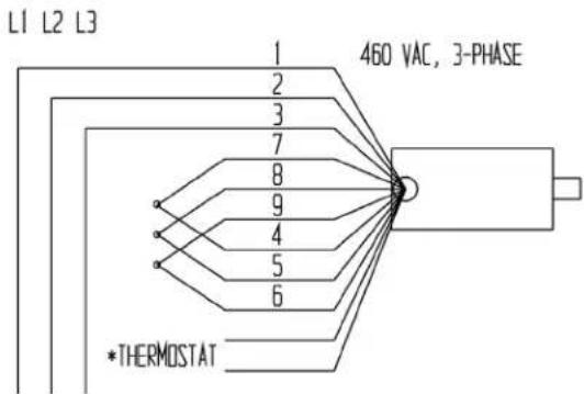
L1 L2 L3
Attach thermostat leads to:
1) Grounded side of the transformer secondary; and
2) Motor relay coil.
It does not matter which lead attaches to each location.
Transformer wiring diagram:

FIG. 12A: DC modular power unit exploded parts diagram and bill of materials *Refer to MPU-GEN2 manual if your unit was manufactured on or after 12-01-2018.*

| Item no. | Part no. | Description | Quantity | Item no. | Part no. | Description | Quantity |
| 1 | 99-016-933 | Base | 1 | 16 | Zb2bz009 | Contact block base | 2 |
| 2 | 21-034-008 | Battery charger | 1 | 17 | Zb2be101 | Contact block, N.O. | 2 |
| 3 | 99-533-008 | Adaptor, hand control 1 18 Zb2ba2c | Operator, black, flush, non-illuminated | 2 | |||
| 4 | 37927 | Tinnerman clip | 4 | 21 | 99-024-010 | Cover, plastic | 1 |
| 5 | 99-023-001 | Reservoir | 1 | 22 | HS52 | Clamp, worm gear hose | 1 |
| 6 | 99-034-013 | Battery strap | 1 | 23 | 01-143-906 | Pump, hydraulic gear | 1 |
| 7 | 99-139-003 | Battery | 1 | *24 | 01-627-010 | Manifold assembly (see p. 16) | 1 |
| 8 | 01-116-003 | Breather, vent, brass fitting | 1 | 25 | 29201 | Screw, machine, 1/4 "-20x 13/4 " | 2 |
| 9 | 15-533-013 | 23" black #4 AWG battery cable | 1 | 26 | 29185 | Screw, machine, 1/4 "-20x1" | 2 |
| 10 | 15-533-014 | 23" black #4 AWG battery cable | 1 | 27 | 2325533687 | Bolt, socket head, 5/16 "-18x1"Washer, lock, 5/16 " | 44 |
| 11 | 23305 | 3/8 "-16x1" socket head bolt | 2 | Molded cord, charger connect | 1 | ||
| 33688 | 3/8 " lock washer | 2 | 28 | 152400-03 | |||
| 33008 | 3/8 " flat washer | 2 | |||||
| 12 | 99-135-011 | Motor | 1 | 29 | 21-034-025 | Flanged inlet w/ locking ring | 1 |
| 13 | 15-022-004 | Relay, start solenoid | 1 | 30 | 3MTST3540 | 1" hook & loop strip | 10" |
| 14 | HS64 | Clamp, worm gear hose | 1 | ||||
| 15 | BG-12V | Gauge, battery, charge indicator | 1 |
FIG. 12B: AC modular power unit exploded parts diagram and bill of materials *Refer to MPU-GEN2 manual if your unit was manufactured on or after 12-01-2018.*

| Item | Part no. | Description | Qty. | Item | Part no. | Description | Qty. |
| 1 | 99-016-933 | MPU base bracket | 1 | 15 | 99-024-029 | Plastic cover (gray) | 1 |
| 2 | Electric box assembly | 1 | 16 | 99-034-008 | Coil, 24V AC | 1 | |
| 3 | 21-034-005 | Connector, flanged inlet plug | 1 | 17 | 99-153-006 | Valve, pressure relief | 1 |
| 4 | 37927 | U nut | 4 | 18 | 99-144-007 | O-Ring | 1 |
| 5 | 99-023-001 | Reservoir | 1 | 19 | 99-531-005 | Filter | 1 |
| 6 | Motor brace | 1 | 20 | 99-153-038 | Flow control, 1.0GPM | 1 | |
| 7 | 2325533687 | 5/16" - 18 × 1" socket head bolt 5/16" lock washer | 44 | 21 | 99-135-003 Motor, 3/4 HP 1 | ||
| 8 | 01-116-003 | Breather, vent, brass fitting | 1 | 22 | 11005330043361836102 | 1/4" - 20 - 1" hex head bolt 1/4" flat washer 1/4" lock washer 1/4" - 20 hex nut | 66666 |
| 9 | 29185 | 1/4" - 20 × 1" Phillips head truss machine screw | 2 | ||||
| 10 | 29201 | 1/4" - 20 × 13/4" machine screw | 2 | ||||
| 11 | 233053368833008 | 3/8" - 16 × 1" socket head bolt 3/8" lock washer 3/8" flat washer | 222 | 23 | 01-127-010 | Manifold, LHL standard | 1 |
| 24 | 99-153-011 | Valve, check, #8, 1 bar spring | 1 | ||||
| 25 | 99-144-023 | O-ring, large | 1 | ||||
| 12 | 01-627-010 | LHL manifold assembly | 1 | 26 | 99-144-022 | O-ring | 1 |
| 13 | 01-143-906 | Hydraulic gear pump | 1 | 27 | 99-153-015 | Valve, cartridge, NC | 1 |
| 14 | 99-145-061 | Worm gear hose clamp | 1 | ||||
| A | 71616 | 10-32 x 5/8" truss head machine screw | 4 | F | 99-034-941 | 39" rail, din, aluminum | 3" |
| B | 01-129-001 | Control transformer | 1 | G | 01-029-006 | Junction box with screw lid | 1 |
| C | 132560 | Contactor, motor, UL Listed | 1 | H | 99-029-142 | Plate, enclosure | 1 |
| D | 27531 | 10-32 x 1/4" z-plated machine screw | 4 | I | 99-034-037 | Connector, clamp, NM, Romex | 4 |
| E | 32028 | #8 – 18 x 1/2" self-tapping screw | 4 |
TROUBLESHOOTING
WARNING
DO NOT attempt to resolve any issue discussed below UNTIL the chute is fully lowered and the power connected.
| Issue: | Possible cause(s): | Solution: |
| 1. Power unit doesn't run when white (UP) button is pressed. | 1a. Transformer fuse is blown.b. No supply voltage.c. Upper-travel limit switch is engaged or bad.d. Faulty connection in control circuit.e. Bad control transformer.f. Open motor relay coil.g. (DC units) Low battery voltage. | 1a. Test with meter; replace if bad.b. Test with meter. Check fuses, breakers, and overloads to determine the cause.c. Inspect and test switch. Replace if bad.d. Test all parts of circuit with meter.e. Check for 24 VAC; replace if bad.f. Test with meter; replace if bad.g. Test with meter. Charge battery if low. Is motor relay LED on? |
| 2. Motor runs properly, but chute doesn't move. Motor and pump are quiet. | 2a. Incorrect motor rotation.b. Pump failure.c. Low hydraulic fluid level. | 2a. Verify motor shaft rotates counterclockwise.b. Consult factory for replacement.c. Ensure reservoir is filled. |
| 3. Motor hums, chatters, or buzzes, or some type of squeal can be heard, but the chute does not move or only moves very slowly. | 3a. See 2b above.b. Excess voltage drop to motor because power cord gauge too small, wire run too long, or incoming voltage too low.c. (3-phase motors) Motor is “single-phasing”.d. Pressure relief opening at full pressure.e. Contamination holding open the lowering valve or the check valve. | 3a. Same as 2b.b. Check power installation for adequacy. Check incoming voltage while motor is running. Correct problem(s).c. Determine cause of loss of voltage on one phase; correct.d. Check for structural damage or binding of the rollers, etc. Check for chute overload condition.e. Remove and inspect. Clean the valve with mineral spirits. |
| 4. Chute elevates, then drifts down. | 4. See 3e above. | 4. Same as 3e. |
| 5. Chute lowers too slowly. | 5a. Flow control spool is stuck.b. Pinched hose.c. Velocity fuse locking (chute only slowly creeps down). | 5a. Remove plug from FC port; push down on the center of the flow spool to ensure it moves freely.b. Check pressure, supply, and return hoses for kinks.c. Same as 7 (below). |
| 6. Chute lowers too quickly. | 6a. See 3e.b. Flow control spool is stuck. | 6a. Same as 3e.b. Same as 5a. |
| 7. Spongy or jerky chute motion. | 7. Air in the hydraulic cylinders. | 7. Bleed air per procedure described on p. 13 of this manual. |
LABELING DIAGRAM
Each unit should be labeled as shown in the diagram. However, label content and location are subject to change so your product might not be labeled exactly as shown. Compare this diagram to your Record of Satisfactory Condition. If there are differences between actual labeling and this diagram, adapt the diagram to reflect actual labeling. Replace all labels that are damaged, missing, or not easily readable (e.g. faded). To order replacement labels or to inquire whether your unit is properly labeled, contact the technical service and parts department online at http://www.vestilmfg.com/parts_info.htm or by calling (260) 665-7586 and asking for the Parts Department.
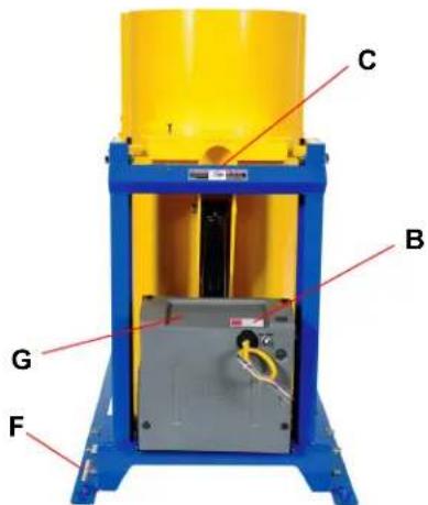
A: Label 287 (model, capacity, serial no.)
| DATE / FECHA/DATE | |
| MODEL/ MODELO/ MODELÉ | |
| SERIAL/ SERIE/ SÉRIE | |
| CAPACITY/ CAPACIDAD/ CAPACITÉ | |
| SUPPLY VOLTAGE/ SUMINISTRO DE VOLTAJE/TENSION D'ALIMENTATION: | AC |
| FREQUENCY/ FRECUENCIA/ FRÉQUENCE: | HZ |
| PHASE/ FASE/ PHASE: | |
| FULL LOAD AMPS/ AMPS DE CARGA COMPLETA/COURANT À PLEINE CHARGE: | A |
| ELECTRICAL DIAGRAM/ DIAGRAMA ELECTRICO/SCHÉMA ÉLECTRIQUE: | |
C: Label 220 (both sides of chute; "Keep clear when in use")
| WARNING | ADVERTENCIA | AVERTISSEMENT |
| KEEP CLEARWHEN IN USE | MANTENGASE ALEJADOCUANDO SE ESTA OPERANDO | SE TENIR À DISTANCELORS DU FONCTIONNEMENT |
E: Label 208 (both sides of frame; "Keep clear of pinch point")
| WARNING | ADVERTENCIA | AVERTISSEMENT |
| KEEP CLEAR OF PINCH POINT | MANTENGASE ALEJADO DEL PUNTO DE CORTE | SE TENIR À DISTANCE DU POINT DE PINCEMENT2014 |
F: Label 204 (both sides; "Secure frame to floor")
| ▲WARNING | ▲ADVERTENCIA | ▲AVERTISSEMENT |
| SECURE FRAME TO FLOOR | ASEGURE EL BASTIDOR AL PISO | FIXER SOLIDEMENT LE CADRE AU PLANCHER |
G: Label 206 (on reservoir inside; hydraulic fluid specifications)


B: Label 221 (risk of electric shock)

D: Label 248 or 249 (electrical system specifications)

Label 249

H: Label 717

LIMITED WARRANTY
Vestil Manufacturing Corporation ("Vestil") warrants this product to be free of defects in material and workmanship during the warranty period. Our warranty obligation is to provide a replacement for a defective, original part covered by the warranty after we receive a proper request from the Warrantee (you) for warranty service.
Who may request service?
Only a warrantee may request service. You are a warrantee if you purchased the product from Vestil or from an authorized distributor AND Vestil has been fully paid.
Definition of "original part"?
An original part is a part used to make the product as shipped to the Warrantee.
What is a "proper request"?
A request for warranty service is proper if Vestil receives: 1) a photocopy of the Customer Invoice that displays the shipping date; AND 2) a written request for warranty service including your name and phone number. Send requests by one of the following methods:
US Mail
Vestil Manufacturing Corporation
2999 North Wayne Street, PO Box 507
Angola, IN 46703
Fax
(260) 665-1339
Phone
(260) 665-7586
info@vestil.com
Enter "Warranty service request"
in the subject field.
In the written request, list the parts believed to be defective and include the address where replacements should be delivered. After Vestil receives your request for warranty service, an authorized representative will contact you to determine whether your claim is covered by the warranty. Before providing warranty service, Vestil will require you to send the entire product, or just the defective part (or parts), to its facility in Angola, IN.
What is covered under the warranty?
The warranty covers defects in the following original, dynamic parts: motors, hydraulic pumps, motor controllers, and cylinders. It also covers defects in original parts that wear under normal usage conditions (“wearing parts”), such as bearings, hoses, wheels, seals, brushes, and batteries.
How long is the warranty period?
The warranty period for original dynamic components is 1 year. For wearing parts, the warranty period is 90 days. Both warranty periods begin on the date Vestil ships the product to the Warrantee. If the product was purchased from an authorized distributor, the periods begin when the distributor ships the product. Vestil may, at its sole discretion, extend a warranty period for products shipped from authorized distributors by up to 30 days to account for shipping time.
If a defective part is covered by the warranty, what will Vestil do to correct the problem?
Vestil will provide an appropriate replacement for any covered part. An authorized representative of Vestil will contact you to discuss your claim.
What is not covered by the warranty?
The Warrantee (you) is responsible for paying labor costs and freight costs to return the product to Vestil for warranty service.
Events that automatically void this Limited Warranty.
- Misuse;
- Negligent assembly, installation, operation or repair;
- Installation/use in corrosive environments;
- Inadequate or improper maintenance;
- Damage sustained during shipping;
• Collisions or other accidents that damage the product;
- Unauthorized modifications: Do not modify the product IN ANY WAY without first receiving written authorization from Vestil.
Do any other warranties apply to the product?
Vestil Manufacturing Corp. makes no other express warranties. All implied warranties are disclaimed to the extent allowed by law. Any implied warranty not disclaimed is limited in scope to the terms of this Limited Warranty. Vestil makes no warranty or representation that this product complies with any state or local design, performance, or safety code or standard. Noncompliance with any such code or standard is not a defect in material or workmanship.



- VESTIL MANUFACTURING CORP
- HDD-SERIES HYDRAULIC DRUM DUMPERS
- INSTRUCTION MANUAL
- RECEIVING INSTRUCTIONS
- TECHNICAL SERVICE & REPLACEMENT PARTS
- ELECTRONIC COPIES OF INSTRUCTION MANUALS
- SPECIFICATIONS
- SIGNAL WORDS
- SAFETY INSTRUCTIONS
- WARNING
- NOTICE
- APPLYING FLOOR LOCKS (HDD-##-#-P UNITS ONLY)
- INSTALLATION (STATIONARY UNITS)
- RECORD OF SATISFACTORY CONDITION
- INSPECTIONS: COMPARE RESULTS TO THE RECORD
- SEQUENCE OF OPERATION
- FIG. 10B: 115VAC, UPPER & LOWER LIMIT SWITCHES, ELECTRICAL CIRCUIT DIAGRAM (09124014 REV. C)
- FIG. 10D: 208-230VAC, UPPER & LOWER LIMIT SWITCHES, 1-PHASE ELECTRICAL CIRCUIT DIAGRAM (09124015 REV. C)
- FIG. 10F: 3-PHASE 208-230/460 VAC, UPPER & LOWER LIMIT SWITCHES, ELECTRICAL CIRCUIT DIAGRAM (09124016 REV. C)
- TROUBLESHOOTING
- LABELING DIAGRAM
- LIMITED WARRANTY
- WHO MAY REQUEST SERVICE
- DEFINITION OF "ORIGINAL PART
- WHAT IS A "PROPER REQUEST
- WHAT IS COVERED UNDER THE WARRANTY
- HOW LONG IS THE WARRANTY PERIOD
- IF A DEFECTIVE PART IS COVERED BY THE WARRANTY, WHAT WILL VESTIL DO TO CORRECT THE PROBLEM
- WHAT IS NOT COVERED BY THE WARRANTY
- EVENTS THAT AUTOMATICALLY VOID THIS LIMITED WARRANTY
- DO ANY OTHER WARRANTIES APPLY TO THE PRODUCT
Brand : Vestil
Model : HDD-60-10-P-DC
Category : Chariot élévateur hydraulique