
EH-68-35 - Niveleur de quai Vestil - Free user manual and instructions
Find the device manual for free EH-68-35 Vestil in PDF.


| Product Type | Electric Hydraulic Lift Table |
| Model | EH-68-35 |
| Brand | Vestil |
| Platform Dimensions | 68 in x 35 in (1727 mm x 889 mm) |
| Lift Capacity | 3500 lb (1588 kg) |
| Lift Range | 33 in to 63 in (838 mm to 1600 mm) |
| Weight | Approximately 950 lb (431 kg) |
| Power Source | 110V AC, 60 Hz, single phase |
| Motor Power | 1 HP (0.75 kW) |
| Hydraulic Oil Type | ISO VG 32 or equivalent |
| Control Method | Push-button pendant control |
| Safety Features | Emergency stop button, overload protection, pinch point guards |
| Maintenance | Regularly check hydraulic fluid level and inspect for leaks |
| Cleaning | Wipe with a damp cloth; avoid harsh chemicals |
| Spare Parts Availability | Replaceable parts include hydraulic cylinder, pump unit, and control switch |
| Repairability | Designed for component replacement; repair by qualified technician recommended |
| Certifications | ANSI/ASME B30.9 compliant |
| Operating Environment | Indoor use, dry conditions, temperature 50-104°F (10-40°C) |
| Shipping Dimensions | 74 in x 42 in x 48 in (1880 mm x 1067 mm x 1219 mm) |
| Warranty | 1 year limited warranty |
Frequently Asked Questions - EH-68-35 Vestil
User questions about EH-68-35 Vestil
0 question about this device. Answer the ones you know or ask your own.
Ask a new question about this device
Download the instructions for your Niveleur de quai in PDF format for free! Find your manual EH-68-35 - Vestil and take your electronic device back in hand. On this page are published all the documents necessary for the use of your device. EH-68-35 by Vestil.
USER MANUAL EH-68-35 Vestil
Vestil Manufacturing Corp.
2999 North Wayne Street, P.O. Box 507, Angola, IN 46703
Telephone: (260) 665-7586 -or- Toll Free (800) 348-0868
www.vestil.com info@vestil.com
EH-Series Dock Levelers

Receiving Instructions
After delivery, remove the packaging from the product. Inspect the product closely to determine whether it sustained damage during transport. If damage is discovered, record a complete description of it on the bill of lading. If the product is undamaged, discard the packaging.
NOTE: The end-user is solely responsible for confirming that product design, use, and maintenance comply with laws, regulations, codes, and mandatory standards applied where the product is used.
Technical Service & Replacement Parts
For answers to questions not addressed in these instructions and to order replacement parts, labels, and accessories, call our Technical Service and Parts Department at (260) 665-7586. The department can also be contacted online at https://www.vestil.com/page-parts-request.php.
Electronic copies of Instruction Manuals
Additional copies of this instruction manual may be downloaded from https://www.vestil.com/page-manuals.php.
TABLE OF CONTENTS
PAGE
| Signal Words | 2 |
| Safety Instructions | 2 |
| EH-65, EH-66, EH-68 and EH-610 Exploded View & Bill of Materials | 3 |
| EH-75, EH-76, EH-78 and EH-710 Exploded View & Bill of Materials | 4 |
| Power Unit Exploded View and Bill of Materials [EH-65; EH-66; & EH-68] | 5 |
| Power Unit Exploded View and Bill of Materials [EH-610; EH-75; EH-76; EH-78; & EH-710] | 6 |
| Manifold Exploded View and Bill of Materials [EH-65; EH-66; & EH-68] | 7 |
| Manifold Exploded View and Bill of Materials [EH-610; EH-75; EH-76; EH-78; & EH-710] | 7 |
| Electrical Circuit Diagram, 115V AC, 1-Phase | 8 |
| Electrical Circuit Diagram, 208-230V AC, 1-Phase | 9 |
| Electrical Circuit Diagram, 208V, 230V, & 460V, 3-Phase AC | 10 |
| Electrical System Operation | 11 |
| Hydraulic Circuit Sequence of Operation | 11 |
| Adjusting Hydraulic Settings | 12 |
| Installation | 13 |
| Operating the Dock Leveler | 13, 14, 15 |
| Record of Satisfactory Condition | 15 |
| Troubleshooting | 16 |
| Inspections and Maintenance | 17 - 18 |
| Labeling Diagram | 18 |
| Limited Warranty | 19 |
SIGNAL WORDS
SIGNAL WORDS appear in this manual to draw the reader's attention to important safety-related messages.

DANGER

WARNING

CAUTION
NOTICE
Identifies a hazardous situation which, if not avoided, WILL result in DEATH or SERIOUS INJURY. Use of this signal word is limited to the most extreme situations.
Identifies a hazardous situation which, if not avoided, COULD result in DEATH or SERIOUS INJURY.
Indicates a hazardous situation which, if not avoided, COULD result in MINOR or MODERATE injury.
Identifies practices likely to result in product/property damage, such as operation that might damage the product.
SAFETY INSTRUCTIONS
Vestil strives to identify foreseeable hazards associated with the use of its products, but no manual can address every conceivable risk. Minimize the likelihood of injury by being mindful of the hazards identified below and by inspecting and maintaining the product as instructed in INSPECTIONS & MAINTENANCE on p. 17 - 18.

WARNING
Risks of death or serious personal injuries.
- Read and understand this entire manual before installing, assembling, using, or servicing this dock leveler.
Keep this manual in a location known to persons who use the dock leveler. Read the manual regularly to refresh your understanding of proper use, inspection, and maintenance procedures.
- The leveler presents falling, pinch point, and impact hazards to the user and bystanders. ALWAYS follow these instructions to avoid injury.
- DO weld the dock leveler securely to the dock face before use. DO anchor the dock leveler to the dock if necessary. See the INSTALLATION INSTRUCTIONS on page 13.
- DO NOT install the dock leveler in a dock that is not flat and level. It is acceptable for the driveway surface below the dock to be inclined towards, or away from, the dock face.
- DO inspect the dock leveler for damage or defects prior to use every day. DO NOT use a dock leveler that is damaged or is not working properly. See INSPECTIONS & MAINTENANCE on p. 17-18.
- DO NOT use a dock leveler that has not been welded continuously across its top edge to the dock face. DO NOT use a dock leveler if any welds are cracked.
- DO NOT use a dock leveler that wobbles while operating. Remove it from service until it is restored to SATISFACTORY CONDITION. See RECORD OF SATISFACTORY CONDITION on p. 15.
- DO wear appropriate PPE. At a minimum, use footwear compliant with ASTM F2413 (formerly ANSI Z41-1999) and eye guards compliant with ANSI Z87.1-2010.
- DO NOT use the dock leveler if you tire quickly or easily, or if you have experienced fainting spells. DO NOT use the dock leveler if you are under the influence of alcohol, medication, or other substances that affect your balance or coordination. Only use the dock leveler if you are in good physical health.
- DO NOT use means other than the factory-supplied electronic controls to operate the dock leveler.
- DO maintain a firm footing when operating the dock leveler.
- DO NOT extend the dock leveler while people in the truck bay are within reach of the unit.
- DO NOT store items on the dock leveler. DO NOT attempt to use the dock leveler if objects are on top of it. ALWAYS check the dock leveler for foreign objects before use. Only use this item as intended.
- DO NOT exceed the load limit for the dock leveler. The load limit appears on the data tag. See LABELING DIAGRAM on p. 18.
- DO NOT force the lip plate to extend using your hands or other mechanical means. Remove the leveler from service until it is restored to SATISFACTORY CONDITION.
- DO inspect the dock leveler as described in INSPECTIONS & MAINTENANCE on page 17-18. DO NOT use the dock leveler unless it is in SATISFACTORY CONDITION (p. 15). Only use manufacturer-approved replacement parts. DO NOT use this product UNLESS every label shown in the LABELING DIAGRAM (page 18) is in place, undamaged, and easily readable.
- DO NOT modify the dock leveler in any way without express, written approval from Vestil Manufacturing. Unapproved modifications automatically void the LIMITED WARRANTY p. 19 and can make the product unsafe to use.
EH-65, EH-66, EH-68 and EH-610 Exploded View and Bill of Materials

| Item | Part no. | Description | Qty. | Item | Part no. | Description | Qty. |
| 1 | 06-514-001 | Frame WeldmentEH-65 | 1 | 10 | 06-014-013 | Maintenance PropEH-65 | 1 |
| 06-514-003 | EH-66 | 06-014-013 | EH-66 | ||||
| 06-514-005 | EH-68 | 06-014-011 | EH-68 | ||||
| 06-514-007 | EH-610 | 06-014-015 | EH-610 | ||||
| 2 | Deck06-513-020 | WeldmentEH-65 | 1 | 11 | 99-134-003 | Tag, Model no., capacity, serial no. | 1 |
| 12 | 06-024-015 | Guard, side skirtEH-65 | 2 | ||||
| 06-513-023 | EH-66 | 06-024-015 | EH-66 | ||||
| 06-513-026 | EH-68 | 06-024-013 | EH-68 | ||||
| 06-513-029 | EH-610 | 06-024-016 | EH-610 | ||||
| 3 | 99-021-933-001 | Cylinder, hydraulic, 2" x 8" piston style with clevis mounts | 1 | 13 | 11107 Hex bolt, gr. A, zinc finish, 3/8 "-16 x 11/4 " | 4 | |
| 4 | 06-521-00106-521-002 | Assembly, cylinder, hydraulic: EH-65; EH-66; and EH-68: 2" x 18" EH-610: 21/2 " x 18" | 1 | 14 | 33008 | Flat washer, low carbon, USS, zinc plated. 3/8 " | 4 |
| 5 | 47-112-001 | Pin, clevis, 1" x 31/4 " | 5 | 15 | 37024 | Nylon insert lock nut, gr. 2, zinc finish, 3/8 "-16 | 2 |
| 6 | 06-112-014 | Pin, clevis, 1" x 21/2 " | 1 | 16 | 51441 | Star pin anchor, 3/16 " x 3/16 " | 2 |
| 7 | 65132 | Extended prong cotter pin, zinc finish, 3/16 " x 31/2 " | 6 | *17 | 29-001-251 | Bumper, laminated dock, 4.5" x 10.25" x 10" | 2 |
| 8 | 11211 Bolt, HHCS, 1/2 "-13UNCx2", zinc plated | 1 | *Not shown in diagram | ||||
| 9 | 36109 | Hex nut, gr. A, plain finish, 1/2 "-13 | 1 | ||||
EH-75, EH-76, EH-78 and EH-710 Exploded View & Bill of Materials

| Item | Part no. | Description | Qty. |
| 1 | 06-514-002 | Weldment, frameEH-75 | 1 |
| 06-514-004 | EH-76 | ||
| 06-514-006 | EH-78 | ||
| 06-514-008 | EH-710 | ||
| 2 | 06-513-120 | Weldment, deckEH-75 | 1 |
| 06-513-123 | EH-76 | ||
| 06-513-126 | EH-78 | ||
| 06-513-129 | EH-710 | ||
| 3 | 06-521-00106-521-002 | Assembly, cylinder, hydraulic: EH-75; EH-76; and EH-78: 2" x 18" EH-710: 2 1/2 " x 18" | 1 |
| 4 | 99-021-933-001 | Cylinder, hydraulic, 2" x 8" piston style with clevis mounts | 1 |
| 5 | 47-112-001 | Pin, clevis, 1" x 3 1/4 " | 5 |
| 6 | 06-024-015 | Guard, side skirtEH-75 | 2 |
| 06-024-015 | EH-76 | ||
| 06-024-013 | EH-78 | ||
| 06-024-016 | EH-710 |
| Item | Part no. | Description | Qty. |
| 7 | 65132 | Extended prong cotter pin, zinc finish, 3/16" × 31/2" | 6 |
| 8 | 06-014-013 | Maintenance propEH-75 | 1 |
| 06-014-013 | EH-76 | ||
| 06-014-011 | EH-78 | ||
| 06-014-015 | EH-710 | ||
| 9 | 11211 Bolt, HHCS, 1/2"-13UNCx2", zinc plated | 1 | |
| 10 | 36109 Hex nut, gr. A, plain finish, 1/2"-13 | 1 | |
| 11 | 11107 Hex bolt, gr. A, zinc finish, 3/8"-16 × 11/4" | 4 | |
| 12 | 33008 | Flat washer, low carbon, USS, zinc plated, 3/8" | 4 |
| 13 | 37024 | Nylon insert lock nut, gr. 2, zinc finish, 3/8"-16 | 2 |
| 14 | 99-134-003 | Tag: model no. capacity, serial no. | 1 |
| 15 | 06-112-014 | Pin, clevis, 1" × 21/2" | 1 |
| 16 | 51441 Star pin anchor, 3/16" × 3/16" | 2 | |
| *17 | 29-001-251 | Bumper, laminated dock, 4.5"x10.25"x10" | 2 |
| * Not shown in diagram | |||
Power Unit Exploded View and Bill of Materials
EH-65, EH-66, & EH-68

| Item | Part no. | Description | Qty. |
| 1 06-627-003 | Subassembly, Manifold, Lift-Lower, Double Acting LIP (detail view on p. 7) | 1 | |
| 2 | 99-137-033-003 | Motor-and-Pump subassembly:208-230V AC, 3-phase, 2HP, 3450rpm, 0.180 displacement | 1 |
| 99-137-033-004 | 460V AC, 3-phase, 2HP, 3450rpm, 0.180 displacement | 1 | |
| 99-137-013-002 | 208-230V AC, 1-phase, 2HP, 3450rpm, 0.122 displacement | 1 | |
| 99-137-008-001 | 115V AC, 1-phase, 0.75HP, 1725rpm, 0.073 displacement | 1 | |
| 99-137-008-002 | 208-230V AC, 1-phase, 0.75HP, 1725rpm, 0.073 displacement | 1 | |
| 3 | 99-116-001 | Suction fitting, mini-manifold | 1 |
| 4 | 33687 | Lock washer, high collar, 5/16 " | 4 |
| 5 | 23255 | 5/16 "-18 x 1" socket head cap screw | 4 |
| 6 | 06-023-003 | Hydraulic tank | 1 |
| 7 | 99-145-061 | Clamp, worm gear hose, 213/16 " - 33/4 " | 1 |
| 8 | 99-144-007 | O-ring, manifold, 3" outer diameter | 1 |
| 9 | 99-031-029 | Accessories, hydraulic | 1 |
| 10 | 01-116-003 | Breather, 1/2 " NPT | 1 |
| 11 | 99-144-009 | O-ring, manifold, 3/4 " outer diameter | 1 |
| 12 | 99-144-008 | O-ring, manifold, 1/2 " outer diameter | 1 |
| 13 | 99-031-033 | Accessories, nipple, close pipe | 1 |
Power Unit Exploded View and Bill of Materials
EH-610, EH-75, EH-76, EH-78, & EH-710

| Item | Part no. | Description | Qty. |
| 1 06-627-004 | Subassembly, Manifold, Lift-Lower, Double Acting LIP (detail view on p. 7) | 1 | |
| 2 | 99-137-033-003 | Motor-and-Pump subassembly:208-230V AC, 3-phase, 2HP, 3450rpm, 0.180 displacement | 1 |
| 99-137-033-004 | 460V AC, 3-phase, 2HP, 3450rpm, 0.180 displacement | 1 | |
| 99-137-013-002 | 208-230V AC, 1-phase, 2HP, 3450rpm, 0.122 displacement | 1 | |
| 99-137-008-001 | 115V AC, 1-phase, 0.75HP, 1725rpm, 0.073 displacement | 1 | |
| 99-137-008-002 | 208-230V AC, 1-phase, 0.75HP, 1725rpm, 0.073 displacement | 1 | |
| 3 | 99-116-001 | Suction fitting, mini-manifold | 1 |
| 4 | 33687 | Lock washer, high collar, 5/16 " | 4 |
| 5 | 23255 | 5/16 "-18 x 1" socket head cap screw | 4 |
| 6 | 06-023-003 | Hydraulic tank | 1 |
| 7 | 99-145-061 | Clamp, worm gear hose, 213/16 " - 33/4 " | 1 |
| 8 | 99-144-007 | O-ring, manifold, 3" outer diameter | 1 |
| 9 | 99-031-029 | Accessories, hydraulic | 1 |
| 10 | 01-116-003 | Breather, 1/2 " NPT | 1 |
| 11 | 99-144-009 | O-ring, manifold, 3/4 " outer diameter | 1 |
| 12 | 99-144-008 | O-ring, manifold, 1/2 " outer diameter | 1 |
| 13 | 99-031-033 | Accessories, nipple, close pipe | 1 |
Manifold Exploded View (06-627-003)
EH-65; EH-66; & EH-68

Return to Power Unit Exploded View on Page 5
| Item | Part no. | Description | Qty. |
| 1 | 06-127-005 | Manifold, hydraulic | 1 |
| 2 99-153-020 | Pilot-to-close check valve | 1 | |
| 3 99-153-004 | Valve pressure relief, 100 bar | 1 | |
| 4 99-153-005 | Valve, pressure relief, 33 bar | 1 | |
| 5 99-153-011 | Check valve, size 08, nose inside-out | 1 | |
| 6 99-153-054 | Cartridge valve, sequence, 3-way, adjustable | 1 | |
| 7 99-153-055 | Cartridge valve, sequence, 2-way with pilot | 1 | |
Manifold Exploded View (06-627-004)
EH-610; EH-75; EH-76; EH-78, & EH-710

Return to Power Unit Exploded View on Page 6
| Item | Part no. | Description | Qty. |
| 1 | 06-127-005 | Manifold, hydraulic 1 | |
| 2 | 99-153-020 | Pilot-to-close check valve | 1 |
| 3 | 99-153-004 | Valve pressure relief, 100 bar | 2 |
| 4 | 99-153-011 | Check valve, size 08, nose inside-out | 1 |
| 5 | 99-153-054 | Cartridge valve, sequence, 3-way, adjustable | 1 |
| 6 | 99-153-055 | Cartridge valve, sequence, 2-way with pilot | 1 |
EH Dock Leveler Electrical Circuit Diagram, 115VAC, 1-phase
06-124-029 rev. B

NOTES:
| Installation Guideline | ||||
| Supplied to motor | Motor FLA | Fusing/Breaker | Wire Go | Max. run fron breaker panel |
| 115V 1∅ | 12 Amps | 20A | 12 AWG | 85 FT. |
-- The wire sizing and maximum run figures given in the chart above are calculated based on the properties of stranded copper THN wire.
Reference motor/pump ossy. drying 06-160-001
- - - - - - Indicates wire and/or components supplied by others
○ Roll Mount Control Enclosure
Junction Box in Frone
WARNING
Turn off all sources of electrical power and lock and tag them out before beginning this n. conduit is recommended for this installation to allow adequate room for auxiliary at might be added in the future, such as dock locks and lights.
Always turn off all power sources before beginning work on this equipment.
The end-user must provide overcurrent and short circuit protection compliant with NEC guidelines and local codes.
EH Dock Leveler Electrical Circuit Diagram, 208-230VAC, 1-phase 06-124-030 rev. A

NOTES:
Reference motor/pump ossy. drowing 06-160-001
- - - - - - - Indicates wire and/or components supplied by others
○ Wall Mount Control Enclosure
Junction Box in Frame
WARNING
Turn off all sources of electrical power and lock and tag them out before beginning this installation. 2in. conduit is recommended for this installation to allow adequate room for auxiliary equipment that might be added in the future, such as dock locks and lights.
Always turn off all power sources before servicing this equipment.
The end-user must provide overcurrent and short circuit protection compliant with NEC guidelines and local codes.
EH Dock Leveler Electrical Circuit Diagram, 208, 230, & 460VAC, 3-phase 06-124-031 rev. A

NOTES:
Reference motor/pump assy. drawing 06-160-001
- - - - - - - Indicates wire and/or components supplied by others
○ Wall Mount Control Enclosure
Junction Box in Frame
WARNING
Turn off all sources of electrical power and lock and tag them out before beginning this n. conduit is recommended for this installation to allow adequate room for auxiliary at might be added in the future, such as dock locks and lights.
Always turn off all power sources before servicing this equipment.
The end-user must provide overcurrent and short circuit protection compliant with NEC guidelines and local codes.
Electrical System Operation
The electric circuit consists of a push-and-hold motor start circuit with thermal protection. The timer circuit activates and runs the motor for approximately 10 seconds. The timer is actuated by either a limit switch in automatic mode, or by pressing the RESET button in manual mode.
![graph TD A["11 LIFT"] --> B["9"] B --> C["10"] C --> D["12 LIP"] D --> E["6"] D --> F["2B"] F --> G["1"] D --> H["6"] H --> I["2A"] I --> J["13"] style A fill:#f9f,stroke:#333 style J fill:#f9f,stroke:#333](/content/2026/07/1459841/images/75ee100c3778f40a1c66ac6886045164f5787da4e2322307d95e2c88c0502511.jpg)
- Manifold
2A. Safety Relief Valve
2B. Lip Relief Valve - Outlet Check Valve
- Pilot to Close Check Valve
- Lip Dump Valve
- Lip Sequence Valve
- Pump
- Motor
- Pressure Compensated Flow Control Valve
- Velocity Fuse
- Deck Cylinder
- Lip Cylinder
- Reservoir
The safety
relief valve (2A) is factory preset to 1500 PSI_DO NOT change the relief valve setting!
WARNING
Hydraulic Circuit Sequence of Operation, EH Series [Numbers in Parentheses () Correspond to Numbers in the Diagram Above]
EH-series dock levelers are hydraulically powered through a sequence of steps. The pressure required to raise the deck varies with deck size. However, the pressure always remains below the pressure setting of the lip sequence valve (6). The sequence valve is factory set to 700 PSI, unless the deck's weight requires a different setting, and should not be changed.
Pressing the "RAISE" button activates the pump. Oil pressure increases until it equals the cracking pressure of the outlet check valve (3). The pressure closes valve (4), a pilot-to-close check valve with a 3:1 ratio. When the pilot pressure exceeds one third of the inlet pressure, the valve closes. As pressure builds in the deck cylinder, the deck rises and the lip rotates outward. When the pressure exceeds 40 PSI, the lip's dump valve, (5), closes. The dump valve is a normally open "pilot-to-close" directional valve.
As the lip rotates outward, oil from the cap end of the lip cylinder (12) is forced across the lip relief valve (2B). The pressure setting of the lip relief valve divides oil flow between the deck cylinder (11) and the lip cylinder (12), and controls the lip's movement. If the pressure is too low, the lip will not fully extend. If pressure is too high, the lip will retract too slowly and fail to return to its stowed position. The lip should completely rotate outward when the deck rises approximately 18 inches.
After the deck cylinder fully extends, hydraulic pressure continues to increase until the lip sequence valve (6) shifts. When the valve shifts, there is pressure on both sides of the lip cylinder. Because there is more pressure applied to the cap end of the cylinder than to the rod end, the lip cylinder retracts.
Releasing the RAISE button deactivates the pump and the hydraulic pressure declines. When the pump output pressure drops below one third of the lift pressure, the pilot-to-close check valve (4) opens and the deck begins to descend. A pressure-compensated flow control valve (9) controls the deck's rate of descent. Pressure continues to decrease after the deck returns to its fully lowered position. When the pressure drops below 40 PSI, the lip dump valve (5) opens and allows the lip to return to its stowed position.
The hydraulic system includes a safety device, called a velocity fuse, which prevents the deck from collapsing if system pressure suddenly drops (for example, if the flow control valve fails or a hose is punctured). The fuse is integrated into the cylinder. When the fuse closes oil cannot flow back to the reservoir.

- Adjust system pressure, controlled by relief value A (RVA) smooth lift refraction can be achieved with careful adjustment. The adjustment process must require a number of cycles to fine tune. However, then the RVB setting must be increased. Turn the adjustment hex clockwise to increase the setting. The adjustment process must be adjusted. Turn the adjustment hex clockwise to increase the system pressure should be adjusted if: 1) the deck won't size; or 2) the fill does not extend. Adjusting the RVA setting requires the use of a pressure connected to the "deck" point on the hyduraltic manifold. Increase pressure by turning the adjustment hex of RVA clockwise. Cycle deck and observe the pressure reading on the gauge. System pressure must exceed 1500 psi. Be sure that adjustment mode to the system pressure does not cause the motor to demand more camps than its ringing. Electrical specifications for the motor appear on a data tag diffixed to it.
- Adjust timing of ip refraction, which is controlled by relief value B (RVB); The ip should drop (teract) offer the deck is fully lowered. If ip refraction timing is off, specifically calloutously remove the maintenance stop from its keeper below the deck. Then, release the RASE button and allow the deck to shift down to its resting position. a. Use a 5mm hex wrench to turn the adjustment hex clockwise until you begin to feel resistance. b. Cycle the deck up and drop a few times and note how quickly the lip drops down or interfaces. c. If the ip either if it represents too quickly when cycling the deck. diffs down to the refacted position while the deck is descending. OR .. if it refers to quickly when cycling the deck.
We are ready to begin adapting the values. 1. Adjust timing of lap extension, which is controlled by the sequence value (SV): The IIP should extend when the deck teaches its fully raised position. However, right now the lap will not kick out when the deck is fully raised because we interested the SV setting to the maximum in step A2 above. Now, we need to decrease the setting. To accomplish this, while until the lap extends.
-
Assuming it has not been adjusted since it left the factory - let's leave it alone for the moment. Now, TURN THE SELECTOR SWITCH for the decadeler to OFF
-
Turn the relief-valve B adjustment counter-clockwise until it feels loose. C. RVA
-
Turn the sequence-valve adjustment clockwise until it stops B. RVB
A. Sequence valve Referring to the diagram below, locate the three valves identified on the drawing to the left.
- 5nm or 3/16" hex wrench . And person to operate the "raise" button at the control panel Lift the deck and insert the maintenance drop
Tools required: . Adjustable wrench . 3/4" hex wrench
Adjuding EH dockeleter hydraulic settings
INSTALLATION
WARNING
Never work under a dock leveler unless the maintenance prop is installed in its socket.
NOTICE
The Dock Leveler must be level to function properly.
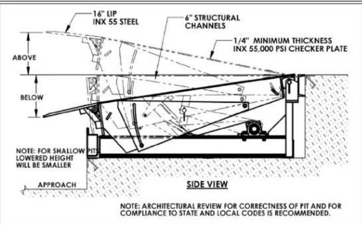
Do not modify the dock leveler to fit in a pit.
- Measure the pit's dimensions.
- Using steel shims, position shims under the frame to prevent frame distortions and flex so the Dock Leveler's final, resting position meets the following:
• The Dock Leveler should be level.
- The Dock Leveler should be against the rear pit curb angle.
- The platform should be centered from side to side within the pit.
- The Dock Leveler's rear channel must be flush with the rear curb angle.
NOTICE
Do not allow the Dock Leveler to be above the pit's rear curb angle.
- With the shims in position, skip weld the rear hinge channel to the rear curb angel, 4 inches every 8 inches.
- Grind welds smooth.
Operating the Dock Leveler
The Dock Leveler has an electric motor directly coupled to a gear-type hydraulic pump to pressurize the hydraulic system. Hydraulic pressure allows the cylinders to lift the platform and extend the lip. The hydraulic control components are housed within a manifold bolted directly onto the gear pump. All hydraulic components are rated for 3,000 psi working pressure.
Power unit parts include:
- Electric motor: The A/C motor operates on either single-phase or 3-phase AC, depending on the motor ordered.
- Gear pump: The pump shaft is coupled directly to the electric motor shaft.
- Pressure relief valve: At pressures greater than 1,500 psi, fluid flows back into the reservoir.
- Lip relief valve: The adjustable valve controls the Lip's retract rate after the platform has risen.
- Check valve: It prevents fluid backflow through the pump.
- Pilot-operated check valve: This valve is closed while the leveler rises and it opens when the pilot pressure drops to less than 1/3 of the inlet pressure, causing the deck to descend.
- Pilot-to-close, two-position valve: Normally open, this valve closes when the pilot pressure exceeds 40 psi. It holds the lip in the extended position until either the platform or the lip is physically supported.
- Pilot-operated sequence valve: When system pressure is \~700 psi, the valve shifts to extend the lip.

- Pressure-compensated flow control valve: Regulates the deck's lowering rate. Located in the deck cylinder's port.
- Hydraulic cylinders:
a. Deck cylinder - A displacement-style cylinder with a bleeder valve located at the top end raises and lowers the deck. The bleeder valve allows air to be removed from the hydraulic system.
b. Lip cylinder - A double-acting cylinder extends and retracts the Lip.
- Safety velocity fuse: Located in the deck cylinder's hose port, it closes quickly in the event of a catastrophic hose failure to prevent the deck from collapsing. The deck remains elevated until pressure is reapplied to the cylinder.
- Hydraulic fluid: The system uses HO150 hydraulic fluid. Anti-wear hydraulic oil with a viscosity grade of 150 SUS at 100°F (ISO 32 at 40°C), such as AW 32 or a non-synthetic transmission fluid is acceptable.
Pressing the RAISE button activates the dock leveler. The motor turns and spins the hydraulic gear pump. Oil is drawn from the reservoir through the suction filter and into the pump. The pump forces pressurized oil through the hydraulic manifold to the deck cylinder. Pressure first acts on the deck cylinder causing it to extend, and then, causes the lip cylinder to extend. When the RAISE button is released, the lip remains extended and the deck descends at a rate determined by the pressure-compensated flow control valve. The lip eventually rests on the back end of the trailer. If the deck descends and contacts the supporting frame, a limit switch is engaged. When in "AUTO" mode, the limit switch causes the leveler to reset itself to the resting/cross-traffic position by turning on the motor for approximately 3 seconds. This brief period is long enough to raise the deck and retract the lip. If the unit is in "MANUAL" mode, engaging the limit switch only causes the lip to drop.
Issues & Solutions: additional solutions are found in the INSPECTIONS AND MAINTENANCE section.
Before beginning work to resolve either of the issues identified below, unload the dock leveler and apply the maintenance prop. To install the prop, press and hold the RAISE button. Continue to hold the button after the deck reaches its maximum elevation. A second person should install the free end of the maintenance prop into the socket on the underside of the deck. Release the RAISE button to allow the maintenance prop to seat firmly in the socket.
- If the deck does not rise while the pump runs, remove the pilot-to-close check valve. Inspect and clean the valve in the following manner:
a. Locate the pilot-to-close check valve, which is identified with the number "4" on the hydraulic manifold, and remove it from the manifold.
b. Inspect the valve for debris. Inspect O-rings & back-up washers for cuts, tears, or other damage.
c. Immerse the valve in mineral spirits or kerosene. Use a thin tool, like a small screwdriver or a small hex wrench, to push the check ball in several times from the bottom end of the valve. The ball should move freely. If it sticks in, the valve might be defective. Replace the valve if the ball still does not move freely after cleaning. Blow the valve off with compressed air, while simultaneously pushing the check ball in-and-out.
d. Inspect the bottom of the valve cavity in the manifold (the chamber in the manifold that houses the valve) for debris. Clean the valve cavity as needed.
e. Reinstall the valve. Tighten the valve in the manifold to approximately 20 lb·ft of torque.
- If the platform lowers slowly or not at all, the velocity fuse of the deck cylinder might be closed. This is typically caused by air in the cylinder. Bleed air from the hydraulic system to correct the problem. Hold a rag over the bleeder valve of the deck cylinder. The valve looks like a grease zerk. Use a 1/4 in. wrench to turn the valve about 1/2 turn. Jog the motor by quickly pressing and releasing the RAISE button. Oil and air will sputter from the valve. Continue this process until air no longer escapes from the valve; then close the valve.
Modes of Operation, EH Series
The leveler can be operated in either of two modes—automatic or manual. Before using the leveler, confirm normal operation by running the leveler through a complete cycle:
1) Automatic mode: Press and hold the "RAISE" button on the remote control box. The deck will rise to its maximum elevation and then the lip will extend. When the lip fully extends, release the "RAISE" button. The deck should lower smoothly until the lip rests on the truck bed. The deck will descend to the fully lowered configuration when the truck pulls away from the dock leaving the lip unsupported. The power unit will restart and raise the deck to maximum elevation; the lip will lower; the power unit will shut off; and the deck will settle in to its stored position flush with the surrounding surface.
NOTICE DO NOT operate in automatic mode if the truck bed is below the level of the dock.
2) Manual mode: Use the leveler in this mode if a truck bed is below dock level. In manual mode, the dock leveler functions nearly identically to automatic mode. However, the power unit does not automatically start to return the deck to the stored position when the leveler reaches the lower limit. Instead, after a truck leaves the deck descends to its fully lowered position and the lip drops to avoid being damaged by the next truck.
"RESET" button: press the button to automatically return the leveler to the stored position while in manual mode.
3) To put the leveler into stored configuration, from either manual or automatic mode, while a truck occupies the loading dock:
a) Press and hold the "RAISE" button until the deck reaches its maximum elevation;
b) Release the button;
c) The leveler will return to its stored position.
4) (Optional) Lip control: "LIP" button on the remote control extends the lip. First, press the "RAISE" button to elevate the deck sufficiently that the lip will not contact the back of the truck as it extends; then press the "LIP" button to extend the lip. Release the "RAISE" and "LIP" buttons and the lip will settle on the bed of the truck. If the RAISE button is released but you continue to hold the LIP button, the leveler will maintain its position. Release the LIP button to allow the lip to settle on the truck bed.
5) Emergency stop button: Pressing this button cuts all power to the unit. If the emergency stop button is pressed at any time during the cycle of operation, the leveler will return to its stored position. Pull out the emergency stop button to reset the switch and restore power.
Record of Satisfactory Condition
Before putting the dock leveler into service, make a record of its appearance and operations. Photograph the unit from multiple vantage points in the lowered and fully elevated and extended configurations. Take close range photographs of all labeling and information tags applied to the machine. Photograph the control box, the deck, the lip, supporting frame, side/foot guards, and anchoring fasteners (anchor bolts, etc.). Describe the motion of the deck as it elevates and descends, e.g. smoothly and evenly from side-to-side without binding or lurching. Describe the sound of the machine as it operates. Collect all photographs and writings in a file. Mark the file appropriately to identify it. This file is a record of the unit in satisfactory condition. Compare the results of all inspections to this RECORD to determine whether the leveler is in satisfactory condition. Do not use the leveler unless it is in satisfactory condition. Purely cosmetic changes, like damaged paint or powdercoat, are not changes from satisfactory condition. However, touchup paint should be applied as soon as damage occurs.
Troubleshooting
The following information is provided to diagnose and correct issues with EH-series dock levelers.
| Issue | Cause | Solution |
| Motor does not run and deck does not rise | 1. Emergency stop button activated (pressed)2. Transformer fuse blown or tripped circuit breaker3. No supply voltage4. Bad control transformer5. Malfunctioning motor relay coil6. Malfunctioning RAISE push button7. Thermal-overload switch tripped | 1. Pull up emergency stop button.2. Replace fuse or reset circuit breaker.3. Test voltage with meter, Check fuses, breakers, and overloads.4. Check for 24VAC; replace if bad.5. Test with meter; replace if bad.6. Test with meter; replace if bad.7. Wait for motor to cool. |
| Motor runs, but deck does not rise and don't hear motor running | 1. Motor rotation is wrong2. Pumps failing to pressurize hydraulic system3. Load on the deck (leveler will only lift its own weight) | 1. Confirm that motor turns clockwise opposite the shaft end.2. Contact the factory.3. Unload the deck. |
| Motor hums or pump squeals but deck does not rise or rises very slowly | 1. Excessive voltage drop to motor because power cord wire size too small, wire length too long, or incoming voltage too low.2. Motor running slowly, is hot, or lost one phase (3-phase motors)3. Pressure relief valve opening at full system pressure.4. Pilot-to-close check valve failing to close5. Load applied to deck | 1. Check power installation. Check incoming voltage while motor running.2. Check voltage on all legs; check fuses; repair as necessary.3. Check for frame damage or binding at the deck hinge, etc. Check for platform overload condition.4. Remove valve and inspect.5. Remove load from deck. |
| Deck does not automatically return to stored position when truck leaves dock | 1. Auto/Manual switch in manual position2. Defective limit switch (deck fails to engage the below dock limit switch, or switch malfunctioning3. Defective timer, or timer period set too short4. Bad (AUTO/Manual) selector switch contact block | 1. Move switch to "auto" position2. Change auto/manual switch to Manual mode and press RESET button.3. Check the timer setting. Test for timer output and replace if bad.4. Test with meter; replace if bad. |
| Deck does not lower | 1. Velocity fuse, item 10, in deck cylinder is locked.2. Pressure-compensated flow control valve stuck. | 1. Press and release RAISE button to unlock fuse. If problem persists, check for air in oil.2. Replace valve. |
| Lip retracts too quickly causing rough action | Lip relief valve, item #2B, pressure setting too low | Turn adjustment on valve clockwise (quarter turn or less) |
| Lip does not retract | Lip relief valve, item #2B, pressure setting too high | Turn adjustment on valve counterclockwise (quarter turn or less) |
| Lip retracts before contacting truck bed | 1. Lip relief valve, item #2B, pressure setting too low2. Faulty lip cylinder, item #12,3. Faulty power unit | 1. Turn adjustment on valve clockwise (quarter turn or less)2. Repair or replace3. Repair or replace |
| Lip does not extend when deck reaches top position | 1. Defective lip cylinder2. Faulty power unit | 1. Repair or replace2. Repair or replace |
Inspections & Maintenance
Before beginning maintenance, secure the deck in the raised configuration with the maintenance prop. The process requires 2 people: one person presses and holds the RAISE button to keep the deck raised with the lip extended, while the second person pivots the maintenance prop to align the free end of the prop with the socket on the underside of the deck.
WARNING
DO NOT use the Dock Leveler if adjustments and/or repairs are incomplete! Return it to after finishing all necessary repairs and adjustments. The reader should understand the between necessary adjustments and repairs, and modifications.
An adjustment is a simple correction that restores the lifter to normal operating condition, such as tightening loose fasteners, or removing dirt or other debris from the surface of the dumper; a repair refers to replacing worn parts with new, factory-approved replacement parts.
A modification is a change that alters the machine from normal operating condition, like bending the structural members or removing a part or several parts. NEVER modify the unit. Modifications automatically void the LIMITED WARRANTY (p.19) and might make the leveler unsafe to use.
NOTICE
Regular maintenance is essential to keep the dock leveler operating properly. ONLY use ISO-aulic fluid or its equal in the hydraulic system.
All inspections and repairs should be performed by qualified persons. Compare the results of each inspection to the RECORD OF SATISFACTORY CONDITION. Do not use the leveler unless every part is in satisfactory condition. If you have any questions about the condition of your lifter, contact the TECHNICAL SERVICE department. [The phone number is provided on the cover page of this manual.] Never make temporary repairs of damaged or missing parts. Only use manufacturer-approved replacement parts to restore the lifter to SATISFACTORY CONDITION.
Inspections
(A) Inspect daily for the following:
1) Frayed wires and loose conduit fittings
2) Damage and deformation of the structural members, cylinder brackets, etc.
3) Run the leveler through a complete cycle. Listen for unusual noises and watch the leveler and lip for binding or unusual movement, or evidence thereof, during operation.
4) Confirm that the side skirt guards are securely fastened to the deck.
(B) Inspect the following each month:
1) Oil leaks – check hoses, cylinders, fittings, etc. for leaks. Check the oil level in the reservoir. Oil should be 1"-1½" below the fill hole in the reservoir. See Yearly Maintenance section for oil specifications.
2) Hydraulic hoses & electrical wiring - look for worn or damaged hydraulic hoses or electrical wires.
3) Hinge and cylinder pivot points – check for excessive wear at pivot points.
4) Welds – check all welds for cracks and signs of metal fatigue, especially at the hinge.
5) Mode functions – cycle the leveler through each mode (AUTO and Manual) to confirm proper functioning in both modes. Carefully watch and listen to the leveler during operation. The leveler should operate without unusual noises or movement.
5) Limit switch - confirm normal operation of the below-dock limit switch in AUTO mode.
6) Hardware – check all hardware/fasteners, especially pivot point pins and pin retaining hardware.
7) Anchorage - closely examine the frame, anchor bolts, and the concrete around the anchor bolts for cracks, warping, etc.
8) Labels – confirm that each label is in place and in good condition.
9) Leveler surfaces - clean dirt and debris from the surfaces of the leveler, especially debris underneath and around the power unit.
(C) Yearly Maintenance: perform biannually if regularly used more than 5 times per day.
1) Grease the lip hinge and all cylinder pivot points.
2) The oil should be changed if it darkens, becomes gritty, or has a milky appearance (indicating the presence of water). Replace with anti-wear hydraulic oil with a viscosity grade of 150 SUS at 100° F, (ISO 32 at 40° C). E.g. AW 32 or HO 150 hydraulic oil or a non-synthetic transmission fluid. Synthetic transmission fluid can be used after flushing the system with the synthetic fluid prior to filling the reservoir.
Labeling Diagram
The unit should be labeled as shown in the diagram. However, label content and location are subject to change so your product might not be labeled exactly as shown. Compare this diagram to your RECORD OF SATISFACTORY CONDITION. Replace all labels that are damaged, missing, or not easily readable (e.g. faded). Order replacement labels by contacting the TECHNICAL SERVICE AND PARTS DEPARTMENT online at http://www.vestilmfg.com/parts_info.htm. Alternatively, you may request replacement parts and/or service by calling (260) 665-7586 and asking the operator to connect you to TECHNICAL SERVICE.

A: Label 367 on both guards (left & right side)
Label 206: Applied to oil tank near fill plug
| ISO 32 / 150 SUS |
| HYDRAULIC OIL OR NON-SYNTHETIC TRANSMISSION FLUIDACEITE HIDRAULICO O LIQUIDOS DE TRANSMISION NO SINTETICOSHUILE OU LIQUIDE HYDRAULIQUE NON-SYNTHÉTIQUE Rev. 1003 |
| VESTIL MANUFACTURING CORPORATION • Phone (260) 665-7586 • www.vestil.com |
B: Data tag 003
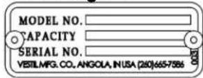
Label 483: On control box

LIMITED WARRANTY
Vestil Manufacturing Corporation ("Vestil") warrants this product to be free of defects in material and workmanship during the warranty period. Our warranty obligation is to provide a replacement for a defective, original part covered by the warranty after we receive a proper request from the Warrantee (you) for warranty service.
Who may request service?
Only a warrantee may request service. You are a warrantee if you purchased the product from Vestil or from an authorized distributor AND Vestil has been fully paid.
Definition of "original part"?
An original part is a part used to make the product as shipped to the Warrantee.
What is a "proper request"?
A request for warranty service is proper if Vestil receives: 1) a photocopy of the Customer Invoice that displays the shipping date; AND 2) a written request for warranty service including your name and phone number. Send requests by one of the following methods:
US Mail
Vestil Manufacturing Corporation
2999 North Wayne Street, PO Box 507
Angola, IN 46703
Fax
(260) 665-1339
Phone
(260) 665-7586
info@vestil.com
Enter "Warranty service
request" in subject field.
In the written request, list the parts believed to be defective and include the address where replacements should be delivered. After Vestil receives your request for warranty service, an authorized representative will contact you to determine whether your claim is covered by the warranty. Before providing warranty service, Vestil will require you to send the entire product, or just the defective part (or parts), to its facility in Angola, IN.
What is covered under the warranty?
The warranty covers defects in the following original, dynamic parts: motors, hydraulic pumps, motor controllers, and cylinders. It also covers defects in original parts that wear under normal usage conditions ("wearing parts"), such as bearings, hoses, wheels, seals, brushes, and batteries.
How long is the warranty period?
The warranty period for original dynamic components is 1 year. For wearing parts, the warranty period is 90 days. Both warranty periods begin on the date Vestil ships the product to the Warrantee. If the product was purchased from an authorized distributor, the periods begin when the distributor ships the product. Vestil may, at its sole discretion, extend a warranty period for products shipped from authorized distributors by up to 30 days to account for shipping time.
If a defective part is covered by the warranty, what will Vestil do to correct the problem?
Vestil will provide an appropriate replacement for any covered part. An authorized representative of Vestil will contact you to discuss your claim.
What is not covered by the warranty?
The Warrantee (you) is responsible for paying labor costs and freight costs to return the product to Vestil for warranty service.
Events that automatically void this Limited Warranty.
- Misuse;
- Negligent assembly, installation, operation or repair;
• Installation/use in corrosive environments; - Inadequate or improper maintenance;
• Damage sustained during shipping;
• Collisions or other accidents that damage the product; - Unauthorized modifications: Do not modify the product IN ANY WAY without first receiving written authorization from Vestil.
Do any other warranties apply to the product?
Vestil Manufacturing Corp. makes no other express warranties. All implied warranties are disclaimed to the extent allowed by law. Any implied warranty not disclaimed is limited in scope to the terms of this Limited Warranty. Vestil makes no warranty or representation that this product complies with any state or local design, performance, or safety code or standard. Noncompliance with any such code or standard is not a defect in material or workmanship.


- VESTIL MANUFACTURING CORP
- RECEIVING INSTRUCTIONS
- TECHNICAL SERVICE & REPLACEMENT PARTS
- ELECTRONIC COPIES OF INSTRUCTION MANUALS
- SIGNAL WORDS
- SAFETY INSTRUCTIONS
- WARNING
- MANIFOLD EXPLODED VIEW (06-627-003)
- MANIFOLD EXPLODED VIEW (06-627-004)
- ELECTRICAL SYSTEM OPERATION
- HYDRAULIC CIRCUIT SEQUENCE OF OPERATION, EH SERIES [NUMBERS IN PARENTHESES () CORRESPOND TO NUMBERS IN THE DIAGRAM ABOVE]
- ADJUDING EH DOCKELETER HYDRAULIC SETTINGS
- INSTALLATION
- NOTICE
- OPERATING THE DOCK LEVELER
- POWER UNIT PARTS INCLUDE
- MODES OF OPERATION, EH SERIES
- NOTICE DO NOT OPERATE IN AUTOMATIC MODE IF THE TRUCK BED IS BELOW THE LEVEL OF THE DOCK
- RECORD OF SATISFACTORY CONDITION
- TROUBLESHOOTING
- INSPECTIONS & MAINTENANCE
- INSPECTIONS
- LABELING DIAGRAM
- LIMITED WARRANTY
- WHO MAY REQUEST SERVICE
- DEFINITION OF "ORIGINAL PART
- WHAT IS A "PROPER REQUEST
- US MAIL
- FAX
- WHAT IS COVERED UNDER THE WARRANTY
- HOW LONG IS THE WARRANTY PERIOD
- IF A DEFECTIVE PART IS COVERED BY THE WARRANTY, WHAT WILL VESTIL DO TO CORRECT THE PROBLEM
- WHAT IS NOT COVERED BY THE WARRANTY
- EVENTS THAT AUTOMATICALLY VOID THIS LIMITED WARRANTY
- DO ANY OTHER WARRANTIES APPLY TO THE PRODUCT
Brand : Vestil
Model : EH-68-35
Category : Niveleur de quai