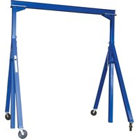
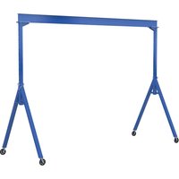
AHS-2-15-9 - Grue d'atelier ajustable Vestil - Free user manual and instructions
Find the device manual for free AHS-2-15-9 Vestil in PDF.


| Product Type | Hydraulic Lift Table |
| Brand | Vestil |
| Model | AHS-2-15-9 |
| Load Capacity | 2,000 lbs (907 kg) |
| Platform Size (L x W) | 36" x 24" (91.4 x 61 cm) |
| Lowered Height | 6" (15.2 cm) |
| Raised Height | 15" (38.1 cm) |
| Power Source | Manual hydraulic pump with foot pedal |
| Weight | 350 lbs (159 kg) |
| Construction Material | Steel with powder coat finish |
| Wheel Options | Optional casters available |
| Safety Features | Locking safety bars, overload relief valve |
| Operation | Foot pedal raise, manual release valve lower |
| Maintenance | Regular lubrication of pivot points, check hydraulic fluid level |
| Cleaning | Wipe with damp cloth; avoid harsh chemicals |
| Spare Parts Availability | Replacement hydraulic units, foot pedals, and safety bars |
| Repair | Sealed hydraulic unit; professional service recommended |
| Certifications | ANSI/ASME safety standards compliant |
| Warranty | 1 year limited warranty |
Frequently Asked Questions - AHS-2-15-9 Vestil
User questions about AHS-2-15-9 Vestil
0 question about this device. Answer the ones you know or ask your own.
Ask a new question about this device
Download the instructions for your Grue d'atelier ajustable in PDF format for free! Find your manual AHS-2-15-9 - Vestil and take your electronic device back in hand. On this page are published all the documents necessary for the use of your device. AHS-2-15-9 by Vestil.
USER MANUAL AHS-2-15-9 Vestil
Vestil Manufacturing Co.
2999 North Wayne Street, P.O. Box 507, Angola, IN 46703
Telephone: (260) 665-7586 -or- Toll Free (800) 348-0868
Fax: (260) 665-1339
Url: www.vestil.com
Email: info@vestil.com
AHS-Series Steel Adjustable-Height Gantry Cranes
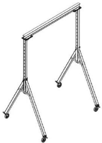
Receiving Instructions
After delivery, remove the packaging from the product. Inspect the product closely to determine whether it sustained damage during transport. If damage is discovered, record a complete description of it on the bill of lading. If the product is undamaged, discard the packaging.
NOTE: The end-user is solely responsible for confirming that product design, use, and maintenance comply with laws, regulations, codes, and mandatory standards applied where the product is used.
Technical Service & Replacement Parts
For answers to questions not addressed in these instructions and to order replacement parts, labels, and accessories, call our Technical Service and Parts Department at (260) 665-7586. The department can also be contacted online at https://www.vestil.com/page-parts-request.php.
Electronic copies of Instruction Manuals
Additional copies of this instruction manual may be downloaded from https://www.vestil.com/page-manuals.php.
| Table of Contents | Page | Table of Figures | Page |
| Specifications...... | 2 - 3 | Fig. A Exploded View AHS-2-10-12, 2-10-14, & 2-10-16.... | 5 |
| Signal Words...... | 4 | Fig. B Exploded View AHS-2-15 series...... | 6 |
| Safety Instructions...... | 4 | Fig. C Exploded View AHS-2-20-12, 2-20-14, & 2-20-16.... | 7 |
| Assembly Instructions...... | 18, 19, 20, 21 | Fig. D Exploded View AHS-4-10-12, 4-10-14, & 4-10-16.... | 8 |
| Using the Crane...... | 22 – 23 | Fig. E Exploded View AHS-4-15 series...... | 9 |
| Festoon Kit...... | 23 | Fig. F Exploded View AHS-4-20-12, 4-20-14, & 4-20-16.... | 10 |
| Record of Satisfactory Condition. | 24 | Fig. G Exploded View AHS-6-10-12, 6-10-14, & 6-10-16.... | 11 |
| National Standards...... | 24 | Fig. H Exploded View AHS-6-15 series...... | 12 |
| Inspections & Maintenance...... | 24 – 25 | Fig. I Exploded View AHS-6-20-12, 6-20-14, & 6-20-16.... | 13 |
| Labeling Diagram...... | 25 | Fig. J Exploded View AHS-8-10-12, 8-10-14, & 8-10-16.... | 14 |
| Limited Warranty...... | 26 | Fig. K Exploded View AHS-8-15 series...... | 15 |
| Fig. L Exploded View AHS-8-20-12, 8-20-14, & 8-20-16.... | 16 | ||
| Fig. M Exploded View AHS-10-15-10.... | 17 |
SPECIFICATIONS
Dimensions, net weight, and capacity information for each AHS-series crane are provided in the tables on pages 2 & 3. However, product design changes might alter specifications, particularly dimensions and net weight, for 1 or more model. Specifications documents for AHS-series cranes are provided on Vestil's website. To access the appropriate specifications document, navigate to the relevant webpage: https://www.vestil.com/product.php?FID=517. Click the "Product Specifications Table" drop-down menu bar partway down the page. Scroll down to the entry for the model you purchased and click the button in the column titled "PDF's" that looks like a pencil inside a box. A PDF file will open. This file is the specifications document. Print a copy of the document and keep it with your copy of this manual. The following is an exemplar specifications document. NOTE: 1 or more models listed in the following tables might be discontinued between revisions of this manual.

| Model | A:Overall width | B:Overall Beam Length | C:Beam height | D:Overall height | E:Usable beam length | F:Height adjustment range | Capacity | Net Weight |
| AHS-2-10-12 | 761/8 in.193.4 cm | 1199/4 in.304.2 cm | 6in.15.2 cm | 14915/16 in.380.8 cm | 893/4 in.228.0 cm | (90 - 144)in.(228.6 - 365.8)cm | 2,000 lb.909 kg | 753.5 lb.342.5kg |
| AHS-2-10-14 | 881/2 in.224.8 cm | 1199/4 in.304.2 cm | 6in.15.2 cm | 1741/16 in.442.1 cm | 893/4 in.228.0 cm | (102 - 168)in.(259.1 - 426.7)cm | 2,000 lb.909 kg | 832.4 lb.378.4 kg |
| AHS-2-10-16 | 881/2 in.224.8 cm | 1199/4 in.304 cm | 6in.15.2 cm | 1981/16 in.503.1 cm | 893/4 in.228.0 cm | (126 - 192)in.(320.0 - 487.7)cm | 2,000 lb.909 kg | 881.0 lb.400.4 kg |
| AHS-2-15-7 | 463/8 in.117.8 cm | 1799/4 in.456.6 cm | 6in.15.2 cm | 903/16 in.229.1 cm | 1499/4 in.380.4 cm | (60 - 84)in.(152.4 - 213.4)cm | 2,000 lb.909 kg | 594.0 lb.270.0 kg |
| AHS-2-15-9 | 583/8 in.148.3 cm | 1799/4 in.456.6 cm | 6in.15.2 cm | 1141/4 in.290.2 cm | 1499/4 in.380.4 cm | (72 - 108)in.(183.0 - 274.3)cm | 2,000 lb.909 kg | 654.4 lb.297.5 kg |
| AHS-2-15-10 | 641/4 in.163.2 cm | 1799/4 in.456.6 cm | 6in.15.2 cm | 126 in.320.0 cm | 1499/4 in.380.4 cm | (78 - 120)in.(198.1 - 304.8)kg | 2,000 lb.909 kg | 737.2 lb.335.1 kg |
| AHS-2-15-12 | 761/8 in.193.4 cm | 1799/4 in.456.6 cm | 6in.15.2 cm | 14915/16 in.380.8 cm | 1499/4 in.380.4 cm | (90 - 144)in.(228.6 - 365.8)cm | 2,000 lb.909 kg | 814.0 lb.370.0 kg |
| AHS-2-15-14 | 881/2 in.224.8 cm | 1799/4 in.456.6 cm | 6in.15.2 cm | 1741/16 in.442.1 cm | 1499/4 in.380.4 cm | (102 - 168)in.(259.1 - 426.7)cm | 2,000 lb.909 kg | 892.9 lb.405.8 kg |
| AHS-2-15-16 | 881/2 in.224.8 cm | 1799/4 in.456.6 cm | 6in.15.2 cm | 1981/16 in.503.1 cm | 1499/4 in.380.4 cm | (126 - 192)in.(320.0 - 487.7)cm | 2,000 lb.909 kg | 941.4 lb.427.9 kg |
| AHS-2-20-12 | 761/8 in.193.4 cm | 2399/4 in.609.0 cm | 101/8 in.25.7 cm | 154 in.391.2 cm | 2099/4 in.532.8 cm | (90 - 144)in.(228.6 - 365.8)cm | 2,000 lb.909 kg | 972.3 lb.442.0 kg |
| AHS-2-20-14 | 881/2 in.224.8 cm | 2399/4 in.609.0 cm | 101/8 in.25.7 cm | 178 1/8 in.452.4 cm | 2099/4 in.532.8 cm | (102 - 168)in.(259.1 - 426.7)cm | 2,000 lb.909 kg | 1051.2 lb.477.8 kg |
| AHS-2-20-16 | 881/2 in.224.8 cm | 2399/4 in.609.0 cm | 101/8 in.25.7 cm | 2021/8 in.513.4 cm | 2099/4 in.532.8 cm | (126 - 192)in.(320.0 - 487.7)cm | 2,000 lb.909 kg | 1099.8 lb.499.9 kg |
| AHS-4-10-12 | 761/8 in.193.4 cm | 1199/4 in.304.2 cm | 81/9 in.20.6 cm | 153 in.388.6 cm | 893/4 in.228.0 cm | (91 - 145)in.(231.2 - 368.3)cm | 4,000 lb.1,818 kg | 763.7 lb.347.2 kg |
| AHS-4-10-14 | 881/2 in.224.8 cm | 1199/4 in.304.2 cm | 81/9 in.20.6 cm | 1771/8 in.449.9 cm | 893/4 in.228.0 cm | (103 - 169)in.(261.7 - 429.3)cm | 4,000 lb.1,818 kg | 843.2 lb.383.3 kg |
| AHS-4-10-16 | 881/2 in.224.8 cm | 1199/4 in.304 cm | 81/9 in.20.6 cm | 2011/8 in.510.9 cm | 893/4 in.228.0 cm | (127 - 193)in.(322.6 - 490.3)cm | 4,000 lb.1,818 kg | 892.1 lb.405.5 kg |
| AHS-4-15-7 | 463/8 in.117.8 cm | 1799/4 in.456.6 cm | 81/9 in.20.6 cm | 931/4 in.236.9 cm | 1499/4 in.380.4 cm | (61 - 85 1/4 )in.(155.0 - 216.6)cm | 4,000 lb.1,818 kg | 644.5 lb.293.0 kg |
| AHS-4-15-9 | 583/8 in.148.3 cm | 1799/4 in.456.6 cm | 81/9 in.20.6 cm | 1175/16 in.298.0 cm | 1499/4 in.380.4 cm | (73 - 109)in.(185.5 - 276.9)cm | 4,000 lb.1,818 kg | 722.8 lb.328.6 kg |
TABLE OF CONTENTS Rev. 5/23/2025 AHS MANUAL
| Model | A:Overall width | B:Overall beam length | C:Beam height | D:Overall height | E:Usable beam length | F:Height adjustment range | Capacity | Net weight |
| AHS-4-15-10 | 64/4in.163.2 cm | 179/4in.456.6 cm | 81/8in.20.6 cm | 129/16in.328.5 cm | 149/4in.380.4 cm | (79 - 121)in.(200.7 - 307.4)cm | 4,000 lb.1,818 kg | 761.6 lb.346.2 kg |
| AHS-4-15-12 | 76/8in.193.4 cm | 179/4in.456.6 cm | 81/8in.20.6 cm | 153 in.388.7 cm | 149/4in.380.4 cm | (91 - 145)in.(231.2 - 368.3)cm | 4,000 lb.1,818 kg | 839.2 lb.381.5 kg |
| AHS-4-15-14 | 88/2in.224.8 cm | 179/4in.456.6 cm | 81/8in.20.6 cm | 177/8in.449.9 cm | 149/4in.380.4 cm | (103 - 169)in.(261.7 - 368.3)cm | 4,000 lb.1,818 kg | 918.7 lb.417.6 kg |
| AHS-4-15-16 | 88/2in.224.8 cm | 179/4in.456.6 cm | 81/8in.20.6 cm | 201/8in.510.9 cm | 149/4in.380.4 cm | (127 - 193)in.(322.6 - 490.3)cm | 4,000 lb.1,818 kg | 967.6 lb.439.9 kg |
| AHS-4-20-12 | 76/8in.193.4 cm | 239/4in.609.0 cm | 123/16in.30.0 cm | 157 in.398.8 cm | 209/4in.532.8 cm | (91 - 145)in.(231.2 - 368.3)cm | 4,000 lb.1,818 kg | 992.0 lb.450.9 kg |
| AHS-4-20-14 | 88/2in.224.8 cm | 239/4in.609.0 cm | 123/16in.30.0 cm | 181/16in.460.3 cm | 209/4in.532.8 cm | (103 - 169)in.(261.7 - 429.3)cm | 4,000 lb.1,818 kg | 1071.4 lb.487.0 kg |
| AHS-4-20-16 | 88/2in.224.8 cm | 239/4in.609.0 cm | 123/16in.30.0 cm | 205/16in.521.2 cm | 209/4in.532.8 cm | (127 - 193)in.(322.6 - 490.3)cm | 4,000 lb.1,818 kg | 1120.3 lb.509.3 kg |
| AHS-6-10-12 | 77/8in.196.5 cm | 119/4in.304.2 cm | 81/8in.20.6 cm | 153 lb.388.6 kg | 89/4in.228.0 cm | (91 - 145)in.(231.1 - 368.3)cm | 6,000 lb.2,727 kg | 856.5 lb.389.3 kg |
| AHS-6-10-14 | 89/4in.228.0 cm | 119/4in.304.2 cm | 81/8in.20.6 cm | 177/8in.449.9 cm | 89/4in.228.0 cm | (103 - 169)in.(261.6 - 429.3)kg | 6,000 lb.2,727 kg | 959.1 lb.436.0 kg |
| AHS-6-10-16 | 89/4in.228.0 cm | 119/4in.304.2 cm | 81/8in.20.6 cm | 201/8in.510.9 cm | 89/4in.228.0 cm | (127 - 193)in.(322.6 - 490.2)kg | 6,000 lb.2,727 kg | 1007.7 lb.458.0 kg |
| AHS-6-15-7 | 47/8in.121.0 cm | 179/4in.456.6 cm | 101/8in.25.7 cm | 95/4in.241.9 cm | 149/4in.380.4 cm | (61 - 85)in.(154.9 - 215.9)cm | 6,000 lb.2,727 kg | 766.4 lb.348.4 kg |
| AHS-6-15-9 | 59/8in.151.4 cm | 179/4in.456.6 cm | 101/8in.25.7 cm | 119/16in.303.1 cm | 149/4in.380.4 cm | (73 - 109)in.(185.4 - 276.9)kg | 6,000 lb.2,727 kg | 844.1 lb.383.7 kg |
| AHS-6-15-10 | 65/2in.166.4 cm | 179/4in.456.6 cm | 101/8in.25.7 cm | 131/16in.333.5 cm | 149/4in.380.4 cm | (79 - 121)in.(200.7 - 307.3)cm | 6,000 lb.2,727 kg | 882.7 lb.401.2 kg |
| AHS-6-15-12 | 77/8in.196.5 cm | 179/4in.456.6 cm | 101/8in.25.7 cm | 155 in.393.7 cm | 149/4in.380.4 cm | (91 - 145)in.(231.1 - 368.3)cm | 6,000 lb.2,727 kg | 960.2 lb.436.5 kg |
| AHS-6-15-14 | 89/4in.228.0 cm | 179/4in.456.6 cm | 101/8in.25.7 cm | 179/8in.455.0 cm | 149/4in.380.4 cm | (103 - 169)in.(261.6 - 429.3)cm | 6,000 lb.2,727 kg | 1062.8 lb.483.1 kg |
| AHS-6-15-16 | 89/4in.228.0 cm | 179/4in.456.6 cm | 101/8in.25.7 cm | 203/8in.515.9 cm | 149/4in.380.4 cm | (127 - 193)in.(322.6 - 490.2)kg | 6,000 lb.2,727 kg | 1111.4 lb.505.2 kg |
| AHS-6-20-12 | 77/8in.196.5 cm | 239/4in.609.0 cm | 125/16in.31.3 cm | 157/4in.399.4 cm | 209/4in.532.8 cm | (91 - 145)in.(231.1 - 368.3)cm | 6,000 lb.2,727 kg | 1305.2 lb.593.3 kg |
| AHS-6-20-14 | 89/4in.228.0 cm | 239/4in.609.0 cm | 125/16in.31.3 cm | 181/8in.460.7 cm | 209/4in.532.8 cm | (103 - 169)in.(261.6 - 429.3)cm | 6,000 lb.2,727 kg | 1407.8 lb.639.9 kg |
| AHS-6-20-16 | 89/4in.228.0 cm | 239/4in.609.0 cm | 125/16in.31.3 cm | 205/8in.93.4 cm | 209/4in.532.8 cm | (127 - 193)in.(322.6 - 490.2)kg | 6,000 lb.2,727 kg | 1456.3 lb.662.0 kg |
| AHS-8-10-12 | 76/2in.194.3 cm | 119/4in.304.2 cm | 81/8in.20.6 cm | 152/8in.388.3 cm | 89/4in.228.0 cm | (91 - 145)in.(231.1 - 368.3)cm | 8,000 lb.3,636 kg | 1047.7 lb.476.2 kg |
| AHS-8-10-14 | 88/16in.224.3 cm | 119/4in.304.2 cm | 81/8in.20.6 cm | 176/16in.448.2 cm | 89/4in.228.0 cm | (103 - 169)in.(261.6 - 429.3)cm | 8,000 lb.3,636 kg | 979.7 lb.445.3 kg |
| AHS-8-10-16 | 88/4in.224.2 cm | 119/4in.304.2 cm | 81/8in.20.6 cm | 200/16in.509.1 cm | 89/4in.228.0 cm | (127 - 193)in.(322.6 - 490.2)cm | 8,000 lb.3,636 kg | 1028.3 lb.467.4 kg |
| AHS-8-15-7 | 45/4in.116.2 cm | 179/4in.456.6 cm | 101/8in.25.7 cm | 94/16in.239.2 cm | 149/4in.380.4 cm | (61 - 85)in.(154.9 - 215.9)cm | 8,000 lb.3,636 kg | 757.8 lb.344.4 kg |
| AHS-8-15-9 | 57/4in.146.7 cm | 179/4in.456.6 cm | 101/8in.25.7 cm | 118/16in.300.2 cm | 149/4in.380.4 cm | (73 - 109)in.(185.4 - 276.9)cm | 8,000 lb.3,636 kg | 850.3 lb.386.5 kg |
| AHS-8-15-10 | 63/4in.161.9 cm | 179/4in.456.6 cm | 101/8in.25.7 cm | 130/4in.330.8 cm | 149/4in.380.4 cm | (79 - 121)in.(200.7 - 307.3)kg | 8,000 lb.3,636 kg | 896.7 lb.407.6 kg |
| AHS-8-15-12 | 76/2in.194.3 cm | 179/4in.456.6 cm | 101/8in.25.7 cm | 154/8in.393.4 cm | 149/4in.380.4 cm | (91 - 145)in.(231.1 - 368.3)cm | 8,000 lb.3,636 kg | 1043 lb.474.1 kg |
| AHS-8-15-14 | 88/16in.224.3 cm | 179/4in.456.6 cm | 101/8in.25.7 cm | 178/2in.453.4 cm | 149/4in.380.4 cm | (103 - 169)in.(261.6 - 429.3)cm | 8,000 lb.3,636 kg | 1083.4 lb.492.5 kg |
| AHS-8-15-16 | 88/4in.224.2 cm | 179/4in.456.6 cm | 101/8in.25.7 cm | 207/16in.526.9 cm | 149/4in.380.4 cm | (127 - 193)in.(322.6 - 490.2)cm | 8,000 lb.3,636 kg | 1132.0 lb.514.5 kg |
| AHS-8-20-12 | 76/2in.194.3 cm | 239/4in.609.0 cm | 125/16in.31.3 cm | 157/8in.399.1 cm | 209/4in.532.8 cm | (91 - 145)in.(231.1 - 368.3)cm | 8,000 lb.3,636 kg | 1496.7 lb.680.3 kg |
| AHS-8-20-14 | 88/16in.224.3 cm | 239/4in.609.0 cm | 125/16in.31.3 cm | 180/16in.458.9 cm | 209/4in.532.8 cm | (103 - 169)in.(261.6 - 429.3)kg | 8,000 lb.3,636 kg | 1428.4 lb.649.3 kg |
| AHS-8-20-16 | 88/4in.224.2 cm | 239/4in.609.0 cm | 125/16in.31.3 cm | 204/16in.519.9 cm | 209/4in.532.8 cm | (127 - 193)in.(322.6 - 490.2)cm | 8,000 lb.3,636 kg | 1476.9 lb.671.3 kg |
| AHS-10-15-10 | 64/2in.163.8 cm | 179/4in.456.6 cm | 121/8in.30.8 cm | 132/4in.335.9 cm | 148/4in.377.8 cm | (78 - 120)in.(198.1 - 304.8)cm | 10,000 lb.4,545 kg | 1033.4 lb.469.7 kg |
SIGNAL WORDS
This manual uses SIGNAL WORDS to indicate the likelihood of personal injuries, as well as the probable seriousness of those injuries, if the product is misused in the ways described. Other signal words call attention to uses of the product likely cause property damage. The signal words used appear below along with the meaning of each word.

Identifies a hazardous situation which, if not avoided, WILL result in DEATH or SERIOUS INJURY. Use of this signal word is limited to the most extreme situations.
Identifies a hazardous situation which, if not avoided, COULD result in DEATH SERIOUS INJURY.
Indicates a hazardous situation which, if not avoided, COULD result in MINOR or MODERATE injury.
Identifies practices likely to result in product/property damage, such as operation that might damage the crane.
SAFETY INSTRUCTIONS
Vestil strives to identify foreseeable hazards associated with the use of its products. However, no manual can address every conceivable risk. The most effective way to avoid injury is to exercise sound judgment when assembling, using, inspecting, and maintaining this crane. Keep a copy of this manual with the crane at all times. For example, put the copy inside a plastic pouch and attach the pouch to the frame.
! DANGER
Electrocution might result if the crane contacts electrified wires.
➢ DO NOT assemble, maintain, or use the crane in an area where it could contact electrified wires.
➢ Regularly inspect electrical wiring in the area where the crane is used. DO NOT contact electrical wiring, especially wiring with exposed conductors (damaged insulation) with the crane.
WARNING
Material handling is dangerous. Improper or careless operation might result in serious personal luce the risk of injury:
- Inspect the usage area each time the crane is used. Make sure that all debris on the ground is removed.
- DO NOT use a damaged or malfunctioning crane. ALWAYS inspect the crane before each use by following the INSPECTIONS & MAINTENANCE instructions on p. 24-25. DO NOT use the crane unless it passes every part of the appropriate inspection, i.e. is in SATISFACTORY CONDITION. See RECORD OF SATISFACTORY CONDITION page 24.
- DO NOT attempt to adjust the height of the crane while a load is applied.
- DO NOT adjust the height of the crane until any hoist and/or trolley is secured at the center of the I-beam. The hoist should not be able to move while height adjustments are performed.
-
DO NOT attempt to lift a load that weighs more than the capacity of your crane. Capacity information for each AHS model crane is provided in the SPECIFICATIONS tables on p. 2-3. Capacity information also appears in the LABELING DIAGRAM section of this manual on p. 25, as well as on capacity labels applied to the crane.
-
Keep clear of the suspended load. DO NOT put any part of your body under a suspended load.
- DO NOT stand beneath or travel under the crane if a load is suspended, and DO NOT permit any person to stand beneath or travel under the load.
- Inform all persons in the area that you are going to use the crane; instruct them to stay clear of the device and the supported load during operation.
- DO NOT lift people with the crane. DO NOT lift loads over people.
- DO NOT allow people to climb on the load or the crane.
- DO NOT operate manual motions with other than manual power.
- DO NOT push or pull the crane with a vehicle. Slowly & carefully push the trailing end of the crane to move it. DO NOT stand beneath the I-beam while pushing the crane. Only traverse even, level ground.
- ALWAYS load the crane in accordance with PROPER LOADING recommendations on p. 22-23.
- DO NOT lift a load unless it is centered under your hoist. A swinging load might cause serious injury.
- DO NOT remove or obscure any label on the crane. DO NOT use the crane if any label is damaged, missing, or not easily readable. See LABELING DIAGRAM on p. 25. Contact Vestil for replacement labels.
- DO NOT modify the crane in any way without the express approval of Vestil in writing. Unapproved modifications automatically void the LIMITED WARRANTY and might make the crane unsafe to use.
- DO NOT use the crane to transport loads. ONLY use the crane to lift loads!
FIG. A: AHS-2-10-12, AHS-2-10-14, & AHS-2-10-16 Exploded View & Bill of Materials 28-006-067

| Item no. | Part no. | Description | Quantity |
| 1 | 33620 | 5/16 in. zinc-plated lock washer | 16 |
| 2 | 11053 | 5/16 in. - 18 x 3/4 in. HHCS #2 zinc-plated bolt | 16 |
| 3 | 28-514-016 | Frame, leg assembly: | |
| AHS-2-10-12 | 2 | ||
| 28-514-017 | AHS-2-10-14 | 2 | |
| 28-514-017 | AHS-2-10-16 | 2 | |
| 4 | 28-514-009 | Assembly frame, upright: | |
| AHS-2-10-12 | 2 | ||
| 28-514-010 | AHS-2-10-14 | 2 | |
| 28-514-124 | AHS-2-10-16 | 2 | |
| 5 | 33006 | 5/16 in. zinc-plated USS flat washer | 16 |
| 6 | 33626 | 1/2 in. zinc-plated lock washer | 8 |
| *7 | 19211-A | 1/2 in. - 13 A325 structural nut | 8 |
| *8 | 19211-B | 1/2 in. - 13 x 2 in. A325 structural bolt | 8 |
| 9 | 16-132-249 | GFN-8/2-S locking caster | 4 |
| 10 | 28-516-053 | Beam clamp (either spur clamp or welded beam clamp) | 4 |
| 11 | 28-014-384 | Frame, domestic steel I-beam | 1 |
| 12 | 28-612-003 | 1 in. x 7 in. retaining pin | 2 |
| 13 | 45282 | #6 hitch pin | 2 |
*Part numbers 19211-A & 19211-B equivalent to, and interchangeable with, part no. 0129020.
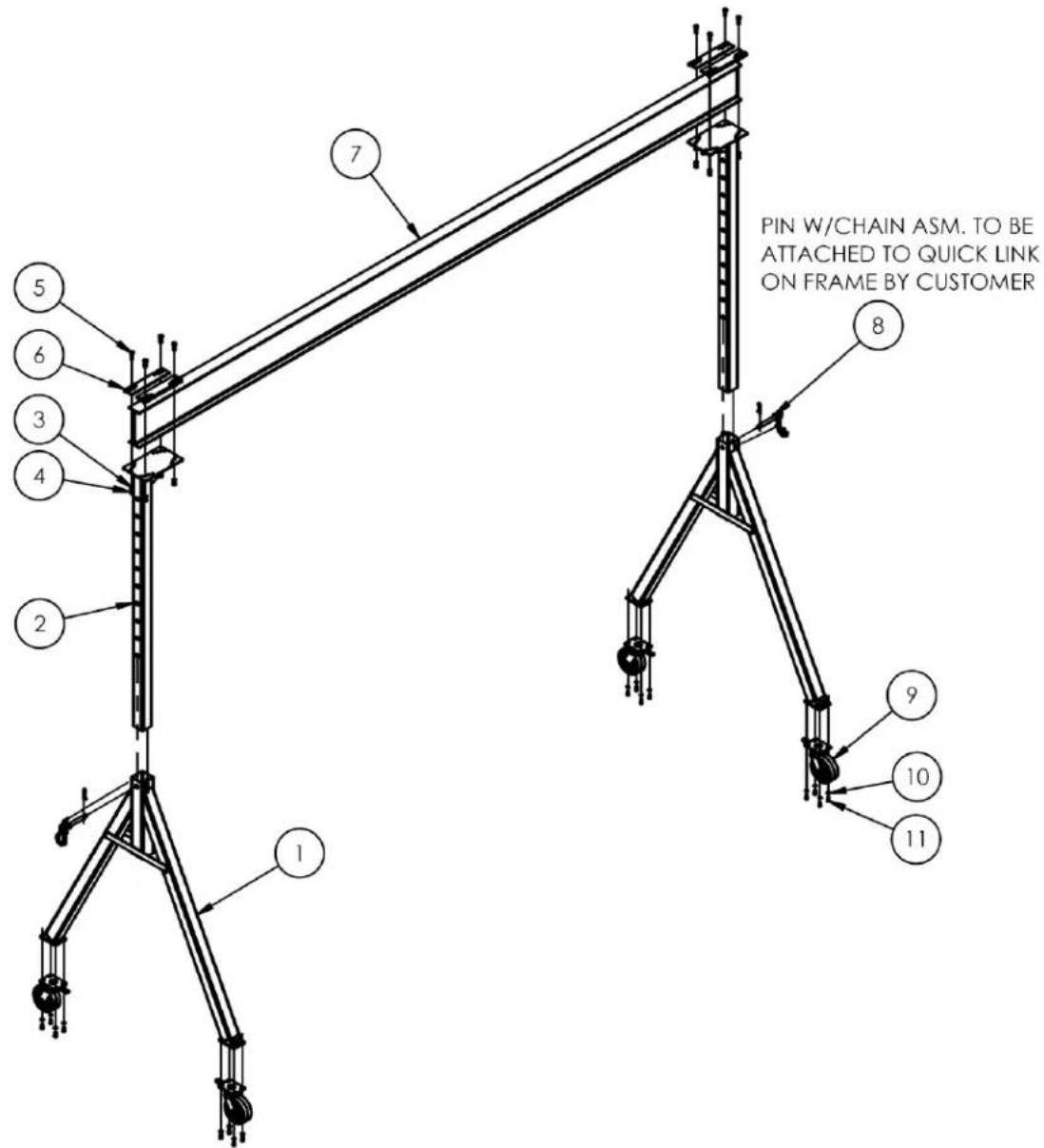
FIG. B: AHS-2-15-7, AHS-2-15-9, AHS-2-15-10, AHS-2-15-12, AHS-2-15-14, AHS-2-15-16 Exploded View & Bill of Materials (28-006-204)

| Item no. | Part no. | Description | Quantity |
| 1 | Frame, leg assembly: | ||
| 28-514-145 | AHS-2-15-7 | 2 | |
| 28-514-144 | AHS-2-15-9 | 2 | |
| 28-514-143 | AHS-2-15-10 | 2 | |
| 28-514-016 | AHS-2-15-12 | 2 | |
| 28-514-017 | AHS-2-15-14 | 2 | |
| 28-514-017 | AHS-2-15-16 | 2 | |
| 2 | Assembly frame, upright: | ||
| 28-514-151 | AHS-2-15-7 | 2 | |
| 28-514-150 | AHS-2-15-9 | 2 | |
| 28-514-149 | AHS-2-15-10 | 2 | |
| 28-514-009 | AHS-2-15-12 | 2 | |
| 28-514-010 | AHS-2-15-14 | 2 | |
| 28-514-124 | AHS-A-15-16 | 2 | |
| 3 | 16-132-249 | GFN-8/2-S locking caster | 4 |
| 4 | 33626 | 1/2 in. zinc-plated lock washer | 8 |
| *5 | 19211-A | 1/2 in. - 13 A325 structural nut | 8 |
| *6 | 19211-B | 1/2 in. - 13 x 2 in. A325 structural bolt | 8 |
| 7 | 33620 | 5/16 in. zinc-plated lock washer | 16 |
| 8 | 11053 | 5/16 in. - 18 x 3/4 in. HHCS #2 zinc-plated bolt | 16 |
| 9 | 33006 | 5/16 in. zinc-plated USS flat washer | 16 |
| 10 | 28-014-263 | Frame, domestic steel l-beam | 1 |
| 11 | 28-516-053 | Weldment, l-beam clamp | 4 |
| 12 | 28-612-003 | 1 in. x 7 in. retaining pin | 2 |
| 13 | 45282 | #6 hitch pin | 2 |
*Part numbers 19211-A & 19211-B equivalent to, and interchangeable with, part no. 0129020.
FIG. C: AHS-2-20-12, AHS-2-20-14, & AHS-2-20-16 Exploded View & Bill of Materials 28-006-071

| Item no. | Part no. | Description | Quantity |
| 1 | 28-514-016 | Frame, leg assembly: | |
| AHS-2-20-12 | 2 | ||
| 28-514-017 | AHS-2-20-14 | 2 | |
| 28-514-017 | AHS-2-20-16 | 2 | |
| 2 | 28-514-009 | Assembly frame, upright: | |
| AHS-2-20-12 | 2 | ||
| 28-514-010 | AHS-2-20-14 | 2 | |
| 28-514-124 | AHS-2-20-16 | 2 | |
| 3 | 16-132-249 | GFN-8/2-S locking caster | 4 |
| 4 | 33626 | 1/2 in. zinc-plated lock washer | 8 |
| *5 | 19211-A | 1/2 in. - 13 A325 structural nut | 8 |
| *6 | 19211-B | 1/2 in. - 13 x 2 in. A325 structural bolt | 8 |
| 7 | 33620 | 5/16 in. zinc-plated lock washer | 16 |
| 8 | 11053 | 5/16 in. - 18 x 3/4 in. HHCS #2 zinc-plated bolt | 16 |
| 9 | 33006 | 5/16 in. zinc-plated USS flat washer | 16 |
| 10 | 28-516-053 | Weldment, l-beam clamp | 4 |
| 11 | 28-014-392 | Frame, domestic steel l-beam | 1 |
| 12 | 28-612-003 | 1 in. x 7 in. retaining pin | 2 |
| 13 | 45282 | #6 hitch pin | 2 |
*Part numbers 19211-A & 19211-B equivalent to, and interchangeable with, part no. 0129020.
FIG. D: AHS-4-10-12, AHS-4-10-14, & AHS-4-10-16 Exploded View & Bill of Materials 28-006-074

| Item no. | Part no. | Description | Quantity |
| 1 | 28-514-016 | Frame, leg assemblyAHS-4-10-12 | 2 |
| 28-514-017 | AHS-4-10-14 | 2 | |
| 28-514-017 | AHS-4-10-16 | 2 | |
| 2 | 28-514-009 | Assembly frame, uprightAHS-4-10-12 | 2 |
| 28-514-010 | AHS-4-10-14 | 2 | |
| 28-514-124 | AHS-4-10-16 | 2 | |
| 3 | 33626 | LOCK WASHER Z PLATED, ∅ 1/2 | 8 |
| *4 | 19211-A | ∅1/2-13 NUT - COMES W/BOLT IN COMBO #19211 | 8 |
| *5 | 19211-B | ∅1/2-13 x 2" A325 BOLT(ORDER COMBO #19211W/NUT) | 8 |
| 6 | 28-516-053 | WELDMENT, I-BEAM CLAMP | 4 |
| 7 | 28-014-387 | FRAME, DOMESTIC STEEL I-BEAM | 1 |
| 8 | 28-612-003 | ASSEMBLY, PIN ADJUSTMENT W/CHAIN | 2 |
| 9 | 16-132-064 | ∅8" x 3" PHENOLIC 4 WAY SWIVEL LOCK CASTER | 4 |
| 10 | 33624 | LOCK WASHER, Z PLATED, ∅ 7/16 | 16 |
| 11 | 13155 | HHCS #5 Z PLATED, GRADE 5, 7/16-14 UNC x 1 LG. | 16 |
*Part numbers 19211-A & 19211-B equivalent to, and interchangeable with, part no. 0129020.
FIG. E: AHS-4-15-7, AHS-4-15-9, AHS-4-15-10, AHS-4-15-12, AHS-4-15-14, & AHS-4-15-16 Exploded View & Bill of Materials (28-006-207)

| Item no. | Part no. | Description | Quantity |
| 1 | Frame, leg assembly: | ||
| 28-514-145 | AHS-4-15-7 | 2 | |
| 28-514-144 | AHS-4-15-9 | 2 | |
| 28-514-143 | AHS-4-15-10 | 2 | |
| 28-514-016 | AHS-4-15-12 | 2 | |
| 28-514-017 | AHS-4-15-14 | 2 | |
| 28-514-017 | AHS-4-15-16 | 2 | |
| 2 | Assembly frame, upright: | ||
| 28-514-151 | AHS-4-15-7 | 2 | |
| 28-514-150 | AHS-4-15-9 | 2 | |
| 28-514-149 | AHS-4-15-10 | 2 | |
| 28-514-009 | AHS-4-15-12 | 2 | |
| 28-514-010 | AHS-4-15-14 | 2 | |
| 28-514-124 | AHS-4-15-16 | 2 | |
| 3 | 33626 | LOCK WASHER Z PLATED, ∅ 1/2 | 8 |
| *4 | 19211-A | ∅1/2-13 NUT - COMES W/BOLT IN COMBO #19211 | 8 |
| *5 | 19211-B | ∅1/2-13 x 2" A325 BOLT(ORDER COMBO #19211 W/NUT) | 8 |
| 6 | 28-516-053 | WELDMENT, I-BEAM CLAMP | 4 |
| 7 | 28-014-388 | FRAME, DOMESTIC STEEL I-BEAM | 1 |
| 8 | 28-612-003 | ASSEMBLY, PIN ADJUSTMENT W/CHAIN | 2 |
| 9 | 16-132-064 | ∅8" x 3" PHENOLIC 4 WAY SWIVEL LOCK CASTER | 4 |
| 10 | 33624 | LOCK WASHER, Z PLATED, ∅ 7/16 | 16 |
| 11 | 13155 | HHCS #5 Z PLATED, GRADE 5, 7/16-14 UNC x 1 LG. | 16 |
*Part numbers 19211-A & 19211-B equivalent to, and interchangeable with, part no. 0129020.
FIG. F: AHA-4-20-12, AHA-4-20-14, & AHA-4-20-16 Exploded View & Bill of Materials 28-006-078
| Item | Part no. | Description | Quantity |
| 1 | 28-514-016 | Frame, leg assembly | |
| AHS-4-20-12 | 2 | ||
| 28-514-017 | AHS-4-20-14 | 2 | |
| 28-514-017 | AHS-4-20-16 | 2 | |
| 2 | 28-514-009 | Assembly frame, upright | |
| AHS-4-20-12 | 2 | ||
| 28-514-010 | AHS-4-20-14 | 2 | |
| 28-514-124 | AHS-4-20-16 | 2 | |
| 3 | 33626 | LOCK WASHER Z PLATED, ∅ 1/2 | 8 |
| *4 | 19211-A | ∅1/2-13 NUT - COMES W/BOLT IN COMBO #19211 | 8 |
| *5 | 19211-B | ∅1/2-13 x 2" A325 BOLT(ORDER COMBO #19211 W/NUT) | 8 |
| 6 | 28-516-053 | WELDMENT, I-BEAM CLAMP | 4 |
| 7 | 28-014-394 | FRAME, DOMESTIC STEEL I-BEAM | 1 |
| 8 | 28-612-003 | ASSEMBLY, PIN ADJUSTMENT W/CHAIN | 2 |
| 9 | 16-132-064 | ∅8" x 3" PHENOLIC 4 WAY SWIVEL LOCK CASTER | 4 |
| 10 | 33624 | LOCK WASHER, Z PLATED, ∅ 7/16 | 16 |
| 11 | 13155 | HHCS #5 Z PLATED, GRADE 5, 7/16-14 UNC x 1 LG. | 16 |
*Part numbers 19211-A & 19211-B equivalent to, and interchangeable with, part no. 0129020.
FIG. G: AHS-6-10-12, AHS-6-10-14, & AHA-6-10-16 Exploded View & Bill of Materials 28-006-080

| Item no. | Part no. | Description | Quantity |
| 1 | 28-514-019 | Frame, leg assemblyAHS-6-10-12 | 2 |
| 28-514-020 | AHS-6-10-14 | 2 | |
| 28-514-020 | AHS-6-10-16 | 2 | |
| 2 | 28-514-009 | Assembly frame, uprightAHS-6-10-12 | 2 |
| 28-514-010 | AHS-6-10-14 | 2 | |
| 28-514-124 | AHS-6-10-16 | 2 | |
| 3 | 16-132-064 | 8in. x 3in. phenolic 4-way swivel lock caster | 4 |
| 4 | 33626 | 1/2 in. zinc-plated lock washer | 8 |
| 5 | 19211-A | 1/2 in. -13 A325 structural nut | 8 |
| 6 | 19211-B | 1/2 in. -13 x 2in. A325 structural bolt | 8 |
| 7 | 33624 | 7/16 in. – 14 zinc-plated lock washer | 16 |
| 8 | 13155 | 7/16 in. – 14 UNC x 1 in. zinc-plated HHCS #5 bolt | 16 |
| 9 | 28-516-053 | Beam clamp (either spur clamp or welded beam clamp) | 4 |
| 10 | 28-014-387 | Frame, domestic steel l-beam | 2 |
| 11 | 28-612-003 | 1 in. x 7 in. retaining pin | 2 |
| 12 | 45282 | #6 hitch pin | 2 |
*Part numbers 19211-A & 19211-B equivalent to, and interchangeable with, part no. 0129020.
FIG. H: AHS-6-15-7, AHS-6-15-9, AHS-6-15-10, AHS-6-15-12, AHS-6-15-14 & AHS-6-15-16 Exploded View & Bill of Materials (28-006-210)

| Item no. | Part no. | Description | Quantity |
| 1 | Frame, leg assembly: | ||
| 28-514-148 | AHS-6-15-7 | 2 | |
| 28-514-147 | AHS-6-15-9 | 2 | |
| 28-514-146 | AHS-6-15-10 | 2 | |
| 28-514-019 | AHS-6-15-12 | 2 | |
| 28-514-020 | AHS-6-15-14 | 2 | |
| 28-514-020 | AHS-6-15-16 | 2 | |
| 2 | Assembly frame, upright: | ||
| 28-514-151 | AHS-6-15-7 | 2 | |
| 28-514-150 | AHS-6-15-9 | 2 | |
| 28-514-149 | AHS-6-15-10 | 2 | |
| 28-514-009 | AHS-6-15-12 | 2 | |
| 28-514-010 | AHS-6-15-14 | 2 | |
| 28-514-124 | AHS-6-15-16 | 2 | |
| 3 | 16-132-064 | 8in. x 3in. phenolic 4-way swivel lock caster | 4 |
| 4 | 33626 | 1/2 in. zinc-plated lock washer | 8 |
| 5 | 19211-A | 1/2 in. -13 A325 structural nut | 8 |
| 6 | 19211-B | 1/2 in. -13 x 2in. A325 structural bolt | 8 |
| 7 | 33624 | 7/16 in. – 14 zinc-plated lock washer | 16 |
| 8 | 13155 | 7/16 in. – 14 UNC x 1 in. zinc-plated HHCS #5 bolt | 16 |
| 9 | 28-516-053 | Beam clamp (either spur clamp or welded beam clamp) | 4 |
| 10 | 28-014-391 | Frame, domestic steel I-beam | 1 |
| 11 | 28-612-003 | 1 in. x 7 in. retaining pin | 2 |
| 12 | 45282 | #6 hitch pin | 2 |
*Part numbers 19211-A & 19211-B equivalent to, and interchangeable with, part no. 0129020.
FIG. I: AHS-6-20-12, AHS-6-20-14, & AHS-6-20-12 Exploded View & Bill of Materials 28-006-084

| Item no. | Part no. | Description | Quantity |
| 1 | 16-132-064 | 8in. x 3in. phenolic 4-way swivel lock caster | 4 |
| 2 | 33626 | 1/2 in. zinc-plated lock washer | 8 |
| *3 | 19211-A | 1/2 in. - 13 A325 structural nut (part of nut and bolt combo.) | 8 |
| *4 | 19211-B | 1/2 in. - 13 x 2 in. structural bolt (part of nut and bolt combo.) | 8 |
| 5 | 33624 | 7/16 in. zinc-plated lock washer | 16 |
| 6 | 13155 | 7/16 in. - 14 UNC x 1 in. HHCS #5 zinc-plated bolt | 16 |
| 7 | 28-514-019 | Frame, leg assembly, gantry crane: | |
| AHS-6-20-12 | 2 | ||
| 28-514-020 | AHS-6-20-14 & AHS-6-20-16 | 2 | |
| 8 | 28-014-417 | Frame, domestic steel l-beam | 1 |
| 9 | 28-514-009 | Assembly frame, upright: | |
| AHS-6-20-12 | 2 | ||
| 28-514-010 | AHS-6-20-14 | 2 | |
| 28-514-124 | AHS-6-20-16 | 2 | |
| 10 | 28-516-053 | Weldment, l-beam clamp | 4 |
| 11 | 28-113-022 | Shim, top plate clamp shim | 4 |
| 12 | 28-612-003 | 1 in. x 7 in. retaining pin | 2 |
| 13 | 45282 | #6 hitch pin | 2 |
*Part numbers 19211-A & 19211-B equivalent to, and interchangeable with, part no. 0129020. TABLE OF CONTENTS Copyright 2022 Vestil Manufacturing Corp. Page 13 of 26
FIG. J: AHS-8-10-12, AHS-8-10-14, & AHS-8-10-16 Exploded View & Bill of Materials 28-006-086

| Item no. | Part no. | Description | Quantity |
| 1 | 28-514-122 | Frame, leg assembly:AHS-8-10-12 | 2 |
| 28-514-123 | AHS-8-10-14 | 2 | |
| 28-514-123 | AHS-8-10-16 | 2 | |
| 2 | 28-514-009 | Assembly frame, upright:AHS-8-10-12 | 2 |
| 28-514-010 | AHS-8-10-14 | 2 | |
| 28-514-124 | AHS-8-10-16 | 2 | |
| 3 | 16-132-064 | 8in. x 3in. phenolic 4-way swivel lock caster | 4 |
| 4 | 33626 | 1/2 in. zinc-plated lock washer | 8 |
| *5 | 19211-A | 1/2 in. -13 A325 structural nut | 8 |
| *6 | 19211-B | 1/2 in. -13 x 2in. A325 structural bolt | 8 |
| 7 | 11209 | 1/2 in. -13 x 11/2 in. zinc-plated HHCS #2 bolt | 16 |
| 8 | 37030 | 1/2 in. -13 nylon insert lock nut | 16 |
| 9 | 28-516-053 | Weldment, l-beam clamp | 4 |
| 10 | 28-014-387 | Frame, domestic steel l-beam | 1 |
| 11 | 28-612-003 | 1 in. x 7 in. retaining pin | 2 |
| 12 | 45282 | #6 hitch pin | 2 |
*Part numbers 19211-A & 19211-B equivalent to, and interchangeable with, part no. 0129020.
FIG. K: AHS-8-15-7, AHS-8-15-9, AHS-8-15-10, AHS-8-15-12, AHS-8-15-14, & AHS-8-15-16 Exploded View & Bill of Materials (28-006-214)

| Item no. | Part no. | Description | Quantity |
| 1 | Assembly frame, upright: | ||
| 28-514-151 | AHS-8-15-7 | 2 | |
| 28-514-150 | AHS-8-15-9 | 2 | |
| 28-514-149 | AHS-8-15-10 | 2 | |
| 28-514-009 | AHS-8-15-12 | 2 | |
| 28-514-010 | AHS-8-15-14 | 2 | |
| 28-514-124 | AHS-8-15-16 | 2 | |
| 2 | 16-132-064 | 8in. x 3in. phenolic 4-way swivel lock caster | 4 |
| 3 | Frame, leg assembly: | ||
| 28-514-155 | AHS-8-15-7 | 2 | |
| 28-514-154 | AHS-8-15-9 | 2 | |
| 28-514-153 | AHS-8-15-10 | 2 | |
| 28-514-122 | AHS-8-15-12 | 2 | |
| 28-514-123 | AHS-8-15-14 | 2 | |
| 28-514-123 | AHS-8-15-16 | 2 | |
| 4 | 33626 | 1/2 in. zinc-plated lock washer | 8 |
| *5 | 19211-A | 1/2 in. -13 A325 structural nut | 8 |
| *6 | 19211-B | 1/2 in. -13 x 2in. A325 structural bolt | 8 |
| 7 | 11209 | 1/2 in. - 13 x 11/2 in. zinc-plated HHCS #2 bolt | 16 |
| 8 | 37030 | 1/2 in. - 13 nylon insert lock nut | 16 |
| 9 | 28-516-053 | Weldment, I-beam clamp | 4 |
| 10 | 28-014-391 | Frame, domestic steel I-beam | 1 |
| 11 | 28-612-003 | 1 in. x 7 in. retaining pin | 2 |
| 12 | 45282 | #6 hitch pin | 2 |
*Part numbers 19211-A & 19211-B equivalent to, and interchangeable with, part no. 0129020.
FIG. L: AHS-8-20-12, AHS-8-20-14, & AHS-8-20-16 Exploded View & Bill of Materials 28-006-090

| Item no. | Part no. | Description | Quantity |
| 1 | 16-132-064 | 8 in. x 3 in. phenolic 4-way swivel lock caster | 4 |
| 2 | 33626 | 1/2 in. zinc-plated lock washer | 8 |
| *3 | 19211-A | 1/2 in. - 13 A325 structural nut (part of nut and bolt combo.) | 8 |
| *4 | 19211-B | 1/2 in. - 13 x 2in. A325 structural bolt (part of nut and bolt combo.) | 8 |
| 5 | 11209 | 1/2 in. - 13 1/2 in. HHCS #2 zinc-plated bolt | 16 |
| 6 | 37030 | 1/2 in. - 13 nylon insert lock nut | 16 |
| 7 | 28-514-12228-514-123 | Frame, leg assembly:AHS-8-20-12AHS-8-20-14 & AHS-8-20-16 | 22 |
| 8 | 28-014-417 | Frame, domestic steel I-beam | 1 |
| 9 | 28-514-00928-514-01028-514-124 | Assembly frame, upright:AHS-8-20-12AHS-8-20-14AHS-8-20-16 | 222 |
| 10 | 28-516-053 | Weldment, I-beam clamp | 4 |
| 11 | 28-113-022 | Shim, top plate clamp shim | 5 |
| 12 | 28-612-003 | 1 in. x 7 in. retaining pin | 2 |
| 13 | 45282 | #6 hitch pin | 2 |
*Part numbers 19211-A & 19211-B equivalent to, and interchangeable with, part no. 0129020.
FIG. M: AHS-10-15-10 Exploded View & Bill of Materials (28-006-215)

| Item no. | Part no. | Description | Quantity |
| 1 | 16-132-243 | 8 x 3 ductile steel caster | 4 |
| 2 | 28-514-157 | Assembly frame, upright | 2 |
| 3 | 28-514-156 | Frame, leg assembly | 2 |
| 4 | 33626 | 1/2 in. zinc-plated lock washer | 8 |
| 5 | 19211-A | 1/2 in. -13 A325 structural nut | 8 |
| 6 | 19211-B | 1/2 in. -13 x 2in. A325 structural bolt | 8 |
| 7 | 11209 | 1/2 in. - 13 x 11/2 in. zinc-plated HHCS #2 bolt | 16 |
| 8 | 37030 | 1/2 in. - 13 nylon insert lock nut | 16 |
| 9 | 28-516-053 | Beam clamp (either spur clamp or welded beam clamp) | 4 |
| 10 | 28-014-393 | Frame, domestic steel l-beam | 1 |
| 11 | 16-132-305 | Batwing, caster position lock | 4 |
| 12 | 28-612-003 | 1 in. x 7 in. retaining pin | 2 |
| 13 | 45282 | #6 hitch pin | 2 |
*Part numbers 19211-A & 19211-B equivalent to, and interchangeable with, part no. 0129020.
ASSEMBLING THE CRANE
WARNING
If the crane is improperly assembled, it might malfunction and result in serious personal
injuries. Read this instruction manual in its entirety before assembling the crane; only assemble the crane if you fully understand both the associated risks and the manufacturer-approved assembly procedure discussed below.
- ONLY qualified personnel should assemble the crane.
• DO NOT modify the crane in any way unless and until you receive written approval from Vestil. - DO NOT use the crane if you notice damage to or deformation of the beam, uprights, or any component of either of the leg assemblies. Using the crane despite weakness of a structural component could result in crane collapse.
- DO NOT use the crane if any of the hardware (bolts, nuts, clamps, etc.) is damaged; you could sustain serious injuries if the crane collapses. Contact Vestil to order replacement parts.
- DO NOT use the crane if any of the casters is damaged. A damaged caster may cause the crane to tip over while hoisting or supporting a load.
NOTICE
- Modifying the crane in any way without first receiving written approval of the modification from Vestil automatically voids the limited warranty.
- The crane is designed for both indoor and outdoor use. However, it should be sheltered from the weather when not in use.
- Inspect the crane for damage before each use.
Step 1A: Fasten the uprights to the leg assemblies (FIG. 1A); then fasten two beam clamps to the beam bracket (FIG. 1a shows diagram for All AHS models except those listed in Step 1B). Lay the leg assemblies (2) flat on the ground. Then, slide the uprights (3) into the corresponding sleeves of the leg assemblies. Insert the telescoping tubes (uprights) until the pinhole in the uprights aligns with the pinhole in the leg assemblies as indicated in Fig. 1A below. Each upright must be pinned to a leg assembly through the same pinhole (diagram below shows pinning through 3d pinhole). To pin an upright to a leg assembly, use a 1 in. x 6 in. retaining pin (see exploded parts diagram that corresponds to your crane model).

Step 1B: [Models AHS-6-20-12, AHS-6-20-14, AHS-6-20-16, AHS-8-20-12, AHS-8-20-14 & AHS-8-2016] Fasten the uprights to the leg assemblies; then fasten two beam clamps to the beam bracket.
Lay the leg assemblies on the ground. Then, slide the uprights into the leg channels of the leg assemblies. Insert the telescoping tubes (uprights) until the 3 rd pinhole in the uprights aligns with the pinhole in the leg assemblies as indicated in Fig. 1B below. Each upright must be pinned to a leg assembly through the same pinhole (diagram below shows pinning through 3 rd pinhole). To pin an upright to a leg assembly, use a 1 in. x 6 in. retaining pin. See exploded view that corresponds to your crane model.
FIG. 1B: Upright-to-Leg Assembly

FIG. 1b: Beam Clamp-to-Beam Bracket
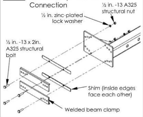

Step 2: Fasten I-beam to uprights. [NOTE: Shim only used in models AHS-6-20-12, AHS-6-20-14, AHS-6-20-16, AHS-8-20-12, AHS-8-20-14 & AHS-8-2016.]
Insert the flange of the I-beam into the gap between the beam clamp and the top of the uprights (circled in FIG. 2B below); then clamp the flange on the opposite side of the beam to the beam bracket with the remaining beam clamps as shown in the diagram below.
FIG. 2A: End View of I-beam Connection to Beam Bracket of Upright
FIG. 2B: Clamp the I-beam to the tops of the uprights


FIG. 2C: Exploded Parts View of Beam Clamp Connection to Beam
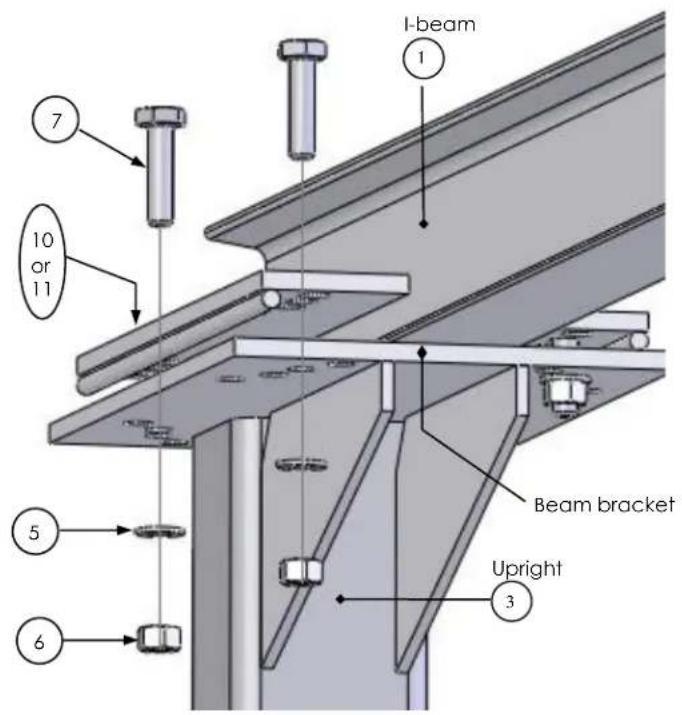
FIG. 2D: Top view of beam connection to upright

| Item no. | Part no. | Description | Quantity |
| 5 | 33626 | 1/2 in. lock washer | 8 |
| *6 | 19211-A | 1/2 in. - 13 structural nut | 8 |
| *7 | 19211-B | 1/2 in. - 13 x 2 in. bolt | 8 |
| 10 or 11 | 28-516-053 | Welded beam clamp | 4 |
*Part numbers 19211-A & 19211-B equivalent to, and interchangeable with, part no. 0129020.
FIG. 2E: Beam clamp connection to beam bracket [Models AHS-6-20-12, AHS-6-20-14, AHS-6-20-16, AHS-8-20-12, AHS-8-20-14 & AHS-8-2016]

FIG. 2F: Close-up view of connection including shim

Step 3: Tighten the beam clamp fasteners to 50 - 52 ft lb of torque.
Step 4: Stand the crane on its feet.
Rotate the crane onto its feet in a controlled manner. For instance, attach a hoist chain to the I-beam and then slowly raise the beam until the crane rotates to stand on its feet. Alternatively, raise the crane with a fork truck. Position the forks under the I-beam and slowly raise the beam until the crane rotates onto its feet in a controlled manner.
Approach the crane with a fork truck from this side, and slide the forks under the I-beam.
Slowly raise the beam and slowly drive forward until the crane stands on its feet.
⚠ WARNING DO NOT raise the beam unless all other persons have moved to a location away from and behind the fork truck.

Step 5: Connect the casters to the legs (instructions show standard casters). Attach each caster to the foot of each leg using the hardware shown in Fig. 5B. Raise the crane 8 to 10 inches off of the ground with a fork lift or hoist. Position a caster underneath each foot as shown in Figures 5A & 5B below. Slide a lock washer (8) followed by a flat washer (10) onto a 1-1/4in. bolt (5), and feed the bolt up through the bolt holes in the caster and foot cap (photo D). Put a lock washer (8) onto the bolt and fasten a nut (7) to the end of the bolt.
FIG. 5A: Caster installation
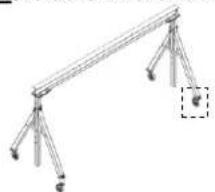
FIG. 5B: AHS 10-15-10

1 1/2 in. - 13 x 2in. HHCS #5 zinc-plated bolt
2 ∅8in. x 3in. ductile steel caster
3 Batwing caster position lock 4 ½ in. - 13 lock nut
FIG. 5C: AHS 2k and 4k models
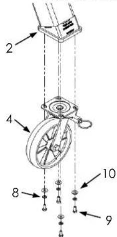
2 Leg Assembly
4 GFN-8/2-S caster
8 5/16 in. zinc-plated lock washer
9 5/16 in. - 18 x 3/4 in. HHCS #2 zinc-plated bolt
FIG. 5D: AHS 6k & 8k models
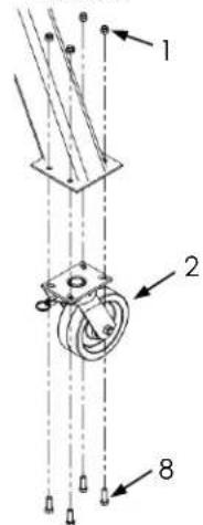
1 1/2in. -13 nylon insert lock nut
2 8in. x 3in. phenolic 4-way swivel lock caster
8 1/2 in. -13 x 1 1/2 in. HHCS #2 zinc-plated bolt
FIG. 5E: Dual pneumatic casters

2 Dual pneumatic caster
3 Caster mount bracket
5 1/2" -13 zinc-plated hex;
nut
6 1/2" zinc finish flat washer

USING THE CRANE
Before using the crane for the first time, perform a BEFORE AND AFTER EACH USE inspection (see p. 24).
WARNING
Crane operators are responsible for operating the crane in a safe manner. To reduce the serious personal injuries or death resulting as a consequence of negligent operation:
- Only qualified, designated crane operators should use this device. The operating instructions in this manual supplement safe crane and hoist operation practices learned during your training program.
- ALWAYS apply the safe material handling practices learned during your training program (for example, practical operating examination).
- All personnel not participating in crane use must stay out of the crane operation area during use. Be certain no part of any person or object is under any part of the boom (l-beam) or the suspended load at any time and particularly before lowering it. Instruct all persons to remain at a safe distance during operation.
• Always carefully watch the boom and any load hanging from it while using the crane.
• Always follow the hoist and trolley manufacturers' instructions regarding proper use of their products. - BEFORE the load is connected to the hoist, lock or immobilize the casters (for instance with chocks).
- DO NOT use the crane and notify your supervisor and authorized maintenance personnel if: 1) you observe any damage or hear unusual noise during operation; 2) if you observe any warping or deformation of the beam, the uprights, the load hook or chain (or cable).
Height adjustment:
Support the I-beam so that the height adjustment pins can be removed, for instance with the tines of a fork truck or by attachment to an overhead hoist. Raise the beam to the desired height; then pin the uprights to the leg assemblies. Each pin must extend completely through the leg assemblies. See Fig. 6.
Proper loading:
Position the trolley and hoist directly above the load. Proper centering requires the operator to center the trolley and hoist above the center of the load as well as to position the long axis of the I-beam above the center of the load. Proper positioning is diagrammed below in Fig 7.
FIG. 7: Proper Load Lifting
Properly centered hoist & trolley

Improperly centered hoist & trolley


Fig. 6: Pin upright at selected height

Connect the load to the hoist chain/cable, according to the instructions supplied with your hoist and the method applied at your work site; then raise the load only as high as is necessary to position it. Once the load is properly centered above the work location, lower the load until it is fully supported by the ground or work surface and disconnect the load from the hoist. Return the crane and hoist to their storage locations.
If you must move the load to a different location, return the load to the ground or other supporting surface, e.g. pallet, and disconnect it from the hoist. Move the crane and load separately to the desired work location. Only use the crane to lift loads.
FESTOON KIT (OPTION)

| Item no. | Part no. | Description | Quantity |
| 2 | 28-016-169 | Hold down plate | 2 |
| 3 | 28-145-002 | I-beam clamp | 4 |
| 4 | 42234 | 3/8 in. -16 x 1in. turned eye bolt | 2 |
| 5 | 33008 | 3/8 in. zinc-plated flat washer | 2 |
| 6 | 36106 | 3/8 in. -16 zinc-plated hex nut | 2 |
| 7 | 37030 | 1/2 in. – 13 nylon insert lock nut | 4 |
| 8 | 11211 | 1/2 in. – 13 x 2 in. HHCS zinc-plated bolt | 4 |
| 9 | 33012 | 1/2 in. zinc-plated USS flat washer | 8 |
| 10 | 45503 | 1/8 in. wire rope (1 in. longer than 1-beam) | 1 |
| 11 | 34785T4 | Quick-grip wire rope clamp | 2 |
| 12 | CV200 | Plastic cable tie | 7 |
| 13 | O-RING15 | Metal ring | 6 |
| 14 | FCOIL 143-001 | Coiled power cord | 1 |
RECORD OF SATISFACTORY CONDITION (THE "RECORD")
Thoroughly inspect the crane after assembling it and before putting it into service. Record the condition and appearance of each of the frame members (I-beam, upright assemblies, leg assemblies), the wheels and/or casters, beam clamp, and all fasteners (bolts, nuts, etc.). Thoroughly photograph the crane from multiple angles. Include close range photographs of the casters and/or wheels, all labeling, and all beam clamp connections. Add the photographs to the record. Collect all photographs and writings in a single file. This file is a record of the crane in satisfactory condition. Compare the results of all INSPECTIONS to this RECORD to determine whether the crane is in satisfactory condition. Do not use the crane unless it is in satisfactory condition. Purely cosmetic changes, like damaged paint or powdercoat, are not changes from satisfactory condition. However, touchup paint should be applied as soon as damage occurs. If your crane is not painted or powdercoated, touchup paint is not required.
NATIONAL STANDARDS
This product is a portable A-frame gantry crane (PGC). ASME standard B30.17 (the "Standard") applies to PGC's. You should acquire a copy of the latest version of the standard. Follow all use and maintenance/care instructions provided in the Standard as well as all other provisions for PGC owners and users. If any content in this manual is inconsistent with a recommendation or mandatory provision in the Standard, apply the provision from the Standard. Vestil encourages you to immediately contact Technical Service to report inconsistencies.
INSPECTIONS AND MAINTENANCE
NOTE: Inspection procedures are included in the most current revision of ASME B30.17. As stated above in the NATIONAL STANDARDS section, Vestil recommends that you acquire a copy of the most recent revision of this standard. Apply all use and maintenance/care instructions in the standard. Vestil also recommends that you contact your local occupational health and safety authority to determine if any laws, regulations, codes, ordinances, etc. apply inspection requirements where the crane is used.
Inspections and all necessary repairs should be performed by qualified persons. Compare the results of each inspection to the RECORD OF SATISFACTORY CONDITION. Do not use the crane unless every part is in satisfactory condition. DON'T GUESS! If you have any questions about the condition of your crane, contact the Technical Service department. The phone number is provided on the cover page of this manual. Never make temporary repairs of damaged or missing parts. Only use manufacturer-approved replacement parts to restore the crane to satisfactory condition.
A. Before and after each use, including first use, unload the crane and inspect the following components:
1) I-Beam - Examine the beam, especially the lower flanges, for bends, cracks, and other damage.
2) Beam clamps and beam clamp fasteners – Clamp connections are shown in Step 2 on p. 19-20. Verify that all lock washers are fully compressed. The clamps should equally overlap the I-beam flange.
3) Beam brackets – Look for cracks, elongations around bolt holes, warps, bends, etc.
4) Casters and caster fasteners - Examine each caster for cracks, warps, tears, grooves, pitting, and significant wear. Push the crane a short distance. All 4 casters should be in continuous contact with the ground. Confirm that the casters roll smoothly without wobbling or skidding. Make sure that caster fasteners are tightly connected. Fastener connections are shown in Step 5 on p. 21.
5) Pins - Check both adjustment pins. Pinned connections are shown in Steps 1A and 1B on p. 18-19. Both adjustment pins should be fully inserted and pin stops should be perpendicular to the pins to secure them in place. All 4 of the clevis pins should be fully inserted and secured in place with cotter pins.
6) Leg assemblies – Inspect both leg assemblies. Look for cracks, bends, warps, and other forms of damage. Pay particular attention to pin holes & bolt holes. Look for elongations, cracks, etc.
B. Monthly inspections – Unload the crane and inspect the following:
1) Beam clamps and beam clamp fasteners – Use a torque wrench to tighten each bolt and nut to 50-52ft·lb. Examine all of the clamps for damage such as deformations and cracks. The I-beam flange should be solidly/immovably clamped to the tops of the uprights.
2) Lay the crane over so that the l-beam is on the ground and inspect:
a) Adjustment pins – One at a time, remove each adjustment pin and examine it. Look for cracks, warps, pitting, and other forms of damage. Confirm that the pin stop operates normally. Reinsert each pin after inspecting it.
b) Leg tubes – Examine the pin holes in the top end of each leg. Look for elongations, cracks, and other forms of damage. Reinstall each leg once its inspection is finished.
C. Once per year: Perform a load test. Lift a load equal to 125% of its rated load (capacity). Only lift the load high enough to ensure that it is entirely supported by the crane. Transport the load by means of your hoist (or hoist & trolley) the full usable length of the I-beam (dimension E in SPECIFICATIONS diagram and table). Return the test load to the ground. Perform inspections A (Before and after each use) and B (Monthly). NOTE: Perform this part C (Load test and a Before & after use inspection) whenever the crane is partially or fully disassembled and reassembled, e.g. after installing replacement parts.
LABELING DIAGRAM
Label content and location are subject to change so your product might not be labeled exactly as shown. Compare the diagram below to your Record of Satisfactory Condition. If there are any differences between actual labeling and this diagram, contact Technical Service. Replace all labels that are damaged, missing, or not easily readable (e.g. faded). To order replacement labels or to inquire whether your unit is properly labeled, contact the technical service and parts department online at http://www.vestilmfg.com/parts_info.htm or by calling (260) 665-7586 and asking for the Parts Department.

LIMITED WARRANTY
Vestil Manufacturing Company ("Vestil") warrants this product to be free of defects in material and workmanship during the warranty period. Our warranty obligation is to provide a replacement for a defective, original part covered by the warranty after we receive a proper request from the Warrantee (you) for warranty service.
Who may request service?
Only a warrantee may request service. You are a warrantee if you purchased the product from Vestil or from an authorized distributor AND Vestil has been fully paid.
Definition of "original part"?
An original part is a part used to make the product as shipped to the Warrantee.
What is a "proper request"?
A request for warranty service is proper if Vestil receives: 1) a photocopy of the Customer Invoice that displays the shipping date; AND 2) a written request for warranty service including your name and phone number. Send requests by one of the following methods:
| US MailVestil Manufacturing Company2999 North Wayne Street, PO Box 507Angola, IN 46703 | Fax(260) 665-1339Phone(260) 665-7586 | Emailinfo@vestil.comWrite “Warranty service request”in the subject field. |
In the written request, list the parts believed to be defective and include the address where replacements should be delivered. After Vestil receives your request for warranty service, an authorized representative will contact you to determine whether your claim is covered by the warranty. Before providing warranty service, Vestil will require you to send the entire product, or just the defective part (or parts), to its facility in Angola, IN.
What is covered under the warranty?
The warranty covers defects in the following original, dynamic parts: motors, hydraulic pumps, motor controllers, and cylinders. It also covers defects in original parts that wear under normal usage conditions ("wearing parts"), such as bearings, hoses, wheels, seals, brushes, and batteries.
How long is the warranty period?
The warranty period for original dynamic components is 1 year. For wearing parts, the warranty period is 90 days. Both warranty periods begin on the date Vestil ships the product to the Warrantee. If the product was purchased from an authorized distributor, the periods begin when the distributor ships the product. Vestil may, at its sole discretion, extend a warranty period for products shipped from authorized distributors by up to 30 days to account for shipping time.
If a defective part is covered by the warranty, what will Vestil do to correct the problem?
Vestil will provide an appropriate replacement for any covered part. An authorized representative of Vestil will contact you to discuss your claim.
What is not covered by the warranty?
The Warrantee (you) is responsible for paying labor costs and freight costs to return the product to Vestil for warranty service.
Events that automatically void this Limited Warranty.
- Misuse;
- Negligent assembly, installation, operation or repair;
• Installation/use in corrosive environments; - Inadequate or improper maintenance;
• Damage sustained during shipping;
• Collisions or other accidents that damage the product; - Unauthorized modifications: Do not modify the product IN ANY WAY without first receiving written authorization from Vestil.
Do any other warranties apply to the product?
Vestil Manufacturing Co. makes no other express warranties. All implied warranties are disclaimed to the extent allowed by law. Any implied warranty not disclaimed is limited in scope to the terms of this Limited Warranty. Vestil makes no warranty or representation that this product complies with any state or local design, performance, or safety code or standard. Noncompliance with any such code or standard is not a defect in material or workmanship.




- VESTIL MANUFACTURING CO
- AHS-SERIES STEEL ADJUSTABLE-HEIGHT GANTRY CRANES
- RECEIVING INSTRUCTIONS
- TECHNICAL SERVICE & REPLACEMENT PARTS
- ELECTRONIC COPIES OF INSTRUCTION MANUALS
- SPECIFICATIONS
- SIGNAL WORDS
- SAFETY INSTRUCTIONS
- DANGER
- WARNING
- ASSEMBLING THE CRANE
- NOTICE
- STEP 4: STAND THE CRANE ON ITS FEET
- USING THE CRANE
- HEIGHT ADJUSTMENT
- PROPER LOADING
- RECORD OF SATISFACTORY CONDITION (THE "RECORD")
- NATIONAL STANDARDS
- INSPECTIONS AND MAINTENANCE
- LABELING DIAGRAM
- LIMITED WARRANTY
- WHO MAY REQUEST SERVICE
- DEFINITION OF "ORIGINAL PART
- WHAT IS A "PROPER REQUEST
- WHAT IS COVERED UNDER THE WARRANTY
- HOW LONG IS THE WARRANTY PERIOD
- IF A DEFECTIVE PART IS COVERED BY THE WARRANTY, WHAT WILL VESTIL DO TO CORRECT THE PROBLEM
- WHAT IS NOT COVERED BY THE WARRANTY
- EVENTS THAT AUTOMATICALLY VOID THIS LIMITED WARRANTY
- DO ANY OTHER WARRANTIES APPLY TO THE PRODUCT
Brand : Vestil
Model : AHS-2-15-9
Category : Grue d'atelier ajustable