
D-250-HD - Trémie industrielle Vestil - Free user manual and instructions
Find the device manual for free D-250-HD Vestil in PDF.


| Product Type | Drum Handler / Dumper |
| Model | D-250-HD |
| Brand | Vestil |
| Capacity | 250 lbs (113 kg) |
| Overall Dimensions | 48" H x 36" W x 42" D (122 x 91 x 107 cm) |
| Weight | 150 lbs (68 kg) |
| Material | Heavy-duty steel with powder coat finish |
| Operation | Manual, hand-operated pump mechanism |
| Functions | Lift, tilt, and transport standard 55-gallon drums |
| Power Source | None (manual operation) |
| Wheel Type | Two swivel casters and two rigid wheels |
| Maintenance | Lubricate pivot points monthly; inspect welds for cracks |
| Cleaning | Wipe with damp cloth; avoid abrasive cleaners |
| Safety Precautions | Do not exceed rated capacity; wear safety shoes and gloves |
| Spare Parts | Replacement casters, pump kits, and handle grips available |
| Warranty | 1 year limited warranty against defects |
| Compliance | ANSI/ASME safety standards |
| Intended Use | Industrial material handling of steel or plastic drums |
| Manual Language | English |
Frequently Asked Questions - D-250-HD Vestil
User questions about D-250-HD Vestil
0 question about this device. Answer the ones you know or ask your own.
Ask a new question about this device
Download the instructions for your Trémie industrielle in PDF format for free! Find your manual D-250-HD - Vestil and take your electronic device back in hand. On this page are published all the documents necessary for the use of your device. D-250-HD by Vestil.
USER MANUAL D-250-HD Vestil
Vestil Manufacturing Co.
2999 North Wayne Street, P.O. Box 507, Angola, IN 46703
Telephone: (260) 665-7586 -or- Toll Free (800) 348-0868
Fax: (260) 665-1339
Website: www.vestil.com e-mail: info@vestil.com
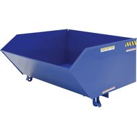
D-SERIES HOPPERS

Receiving instructions
After delivery, remove the packaging from the product. Inspect the product closely to determine whether it sustained damage during transport. If damage is discovered, record a complete description of it on the bill of lading. If the product is undamaged, discard the packaging.
NOTE: The end-user is solely responsible for confirming that product design, use, and maintenance comply with laws, regulations, codes, and mandatory standards applied where the product is used.
Technical Service & Replacement Parts
For answers to questions not addressed in these instructions and to order replacement parts, labels, and accessories, call our Technical Service and Parts Department at (260) 665-7586. The department can also be contacted online at https://www.vestil.com/page-parts-request.php.
Electronic Copies of Instruction Manuals
Additional copies of this instruction manual may be downloaded from https://www.vestil.com/page-manuals.php.
| Table of Contents | Page | Table of Figures | Page |
| Specifications.... | 2, 3, 4 | D-25 exploded view & bill of materials.... | 4 |
| Signal Words.... | 14 | D-33 exploded view & bill of materials.... | 5 |
| Safety Instructions.... | 14 | D-50 exploded view & bill of materials.... | 6 |
| National Standards.... | 15 | D-75 exploded view & bill of materials.... | 7 |
| Using the Hopper.... | 15 - 16 | D-100 exploded view & bill of materials.... | 8 |
| Record of Satisfactory Condition.... | 16 | D-150 exploded view & bill of materials.... | 9 |
| Inspections & Maintenance.... | 16 | D-200 exploded view & bill of materials.... | 10 |
| Labeling Diagram.... | 17 | D-250 exploded view & bill of materials.... | 11 |
| Limited Warranty.... | 18 | D-300 exploded view & bill of materials.... | 12 |
| D-300-HD-NA, D-350-HD, D-400-HD, and D-500-HD exploded view & bill of materials.... | 13 |
SPECIFICATIONS
Dimensions, net weight, and capacity figures are provided in the following tables.
| Light duty fabricated from 12 gauge steel | |||||
| Model | Volume | Capacity | Overall Dimensions(W x L x H) | Distance betweenFork Pocket Centers | Net Weight |
| D-25-LD | 1/4 yd3 (0.19 m3) | 2,000 lb.(909 kg) | 26" x 517/8" x 38"(66.0 x 131.8 x 96.5)cm | 18"(45.7cm) | 341 lb.155 kg |
| D-33-LD | 1/3 yd3 (0.25 m3) | 2,000 lb.(909 kg) | 26" x 517/8" x 38"(66.0 x 131.8 x 96.5)cm | 18"(45.7cm) | 341 lb.155 kg |
| D-50-LD | 1/2 yd3 (0.38 m3) | 2,000 lb.(909 kg) | 329/16" x 513/4" x 38"(85.6 x 131.4 x 96.5)cm | 18"(45.7cm) | 364 lb.165.5 kg |
| D-75-LD | 3/4 yd3 (0.57 m3) | 2,000 lb.(909 kg) | 329/16" x 611/8" x 4211/16"(85.6 x 155.3 x 108.4)cm | 18"(45.7cm) | 448 lb.203.6 kg |
| D-100-LD | 1 yd3(0.76 m3) | 2,000 lb.(909 kg) | 429/16" x 611/8" x 4211/16"(105.9 x 155.3 x 108.4)cm | 18"(45.7cm) | 478 lb.217.3 kg |
| D-150-LD | 11/2 yd3 (1.15 m3) | 2,000 lb.(909 kg) | 429/16" x 685/16" x 5113/16"(111.0 x 173.5 x 131.6)cm | 28"(71.1cm) | 565 lb.256.8 kg |
| D-200-LD | 2 yd3(1.53 m3) | 2,000 lb.(909 kg) | 5611/16" x 685/16" x 513/16"(144.0 x 173.5 x 130.0)cm | 28"(71.1cm) | 612 lb.278.2 kg |
| D-250-LD | 21/2 yd3 (1.91 m3) | 2,000 lb.(909 kg) | 699/16" x 683/8" x 513/4"(176.7 x 173.7 x 131.4)cm | 28"(71.1cm) | 863 lb.392.3 kg |
| D-300-LD | 3 yd3(2.29 m3) | 2,000 lb.(909 kg) | 813/4" x 685/8" x 513/16"(207.6 x 174.3 x 130.0)cm | 28"(71.1cm) | 940 lb.427.3 kg |
| Medium fabricated from 10 gauge steel | |||||
| D-25-MD | 1/4 yd3 (0.19 m3) | 4,000 lb.(1,818 kg) | 26" x 513/8" x 381/16"(66.0 x 130.5 x 96.7)cm | 18"(45.7cm) | 396 lb.180 kg |
| D-33-MD | 1/3 yd3 (0.25 m3) | 4,000 lb.(1,818 kg) | 26" x 513/8" x 381/16"(66.0 x 130.5 x 96.7)cm | 18"(45.7cm) | 396 lb.180 kg |
| D-50-MD | 1/2 yd3 (0.38 m3) | 4,000 lb.(1,818 kg) | 329/16" x 517/8" x 381/16"(85.2 x 131.8 x 96.7)cm | 18"(45.7cm) | 435 lb.197.7 kg |
| D-75-MD | 3/4 yd3 (0.57 m3) | 4,000 lb.(1,818 kg) | 329/16" x 611/8" x 423/4"(80.2 x 155.3 x 108.6)cm | 18"(45.7cm) | 542 lb.246.4 kg |
| D-100-MD | 1 yd3(0.76 m3) | 4,000 lb.(1,818 kg) | 429/16" x 611/8" x 423/4"(105.6 x 155.3 x 108.6)cm | 18"(45.7cm) | 590 lb.268.2 kg |
| D-150-MD | 11/2 yd3 (1.15 m3) | 4,000 lb.(1,818 kg) | 429/16" x 683/8" x 5113/16"(110.6 x 173.7 x 131.6)cm | 28"(71.1cm) | 714 lb.324.5 kg |
| D-200-MD | 2 yd3(1.53 m3) | 4,000 lb.(1,818 kg) | 565/8" x 685/16" x 5113/16"(1430. x 173.5 x 131.6)cm | 28"(71.1cm) | 700 lb.318.2 kg |
| D-250-MD | 21/2 yd3 (1.91 m3) | 4,000 lb.(1,818 kg) | 699/16" x 683/8" x 513/4"(176.7 x 173.7 x 131.4)cm | 28"(71.1cm) | 863 lb.392.3 kg |
| D-300-MD | 3 yd3(2.29 m3) | 4,000 lb.(1,818 kg) | 813/4" x 685/8" x 5113/16"(207.6 x 174.3 x 131.6)cm | 28"(71.1cm) | 940 lb.427.3 kg |
| Heavy duty fabricated from 8 gauge steel | |||||
| D-25-HD | 1/4 yd3 (0.19 m3) | 6,000 lb.(2,727.3 kg) | 26" x 517/8" x 381/16"(66.0 x 131.8 x 96.7)cm | 18"(45.7cm) | 396 lb.180 kg |
| D-33-HD | 1/3 yd3 (0.25 m3) | 6,000 lb.(2,727.3 kg) | 26" x 517/8" x 381/16"(66.0 x 131.8 x 96.7)cm | 18"(45.7cm) | 396 lb.180 kg |
| D-50-HD | 1/2 yd3 (0.38 m3) | 6,000 lb.(2,727.3 kg) | 329/16" x 517/8" x 381/16"(82.7 x 131.8 x 96.7)cm | 18"(45.7cm) | 435 lb.197.7 kg |
| D-75-HD | 3/4 yd3 (0.57 m3) | 6,000 lb.(2,727.3 kg) | 329/16" x 611/8" x 423/4"(80.2 x 155.3 x 108.6)cm | 18"(45.7cm) | 542 lb.246.4 kg |
| D-100-HD | 1 yd3(0.76 m3) | 6,000 lb.(2,727.3 kg) | 429/16" x 611/8" x 423/4"(105.6 x 155.3 x 108.6)cm | 18"(45.7cm) | 590 lb.268.2 kg |
| D-150-HD | 11/2 yd3 (1.15 m3) | 6,000 lb.(2,727.3 kg) | 429/16" x 683/8" x 5113/16"(110.6 x 173.7 x 131.6)cm | 28"(71.1cm) | 714 lb.324.5 kg |
| D-200-HD | 2 yd3(1.53 m3) | 6,000 lb.(2,727.3 kg) | 569/16" x 685/16" x 5113/16"(143.7 x 173.5 x 131.6)cm | 28"(71.1cm) | 788 lb.358.2 kg |
Table of Contents Rev. 6/17/2024 D MANUAL
| D-250-HD | 21/2 yd3 (1.91 m3) | 6,000 lb. (2,727.3 kg) | 699/16'' × 683/8'' × 513/4'' (176.7 × 173.7 × 131.4) cm | 28"(71.1cm) | 863 lb.392.3 kg |
| D-300-HD | 3 yd3 (2.29 m3) | 6,000 lb. (2,727.3 kg) | 813/4'' × 685/8'' × 5113/16'' (207.6 × 174.3 × 131.6) cm | 28"(71.1cm) | 940 lb.427.3 kg |
| D-300-HD-NA | 3 yd3 (2.29 m3) | 6,000 lb. (2,727.3 kg) | 555/16'' × 793/8'' × 643/8'' (140.5 × 201.6 × 163.5) cm | 28 in.(71.1cm) | 1115 lb.506.8 kg |
| D-350-HD | 31/2 yd3 (2.69 m3) | 6,000 lb. (2,727.3 kg) | 64'' × 793/8'' × 643/8'' (162.6 × 201.6 × 163.5) cm | 28 in.(71.1cm) | 1169 lb.531.4 kg |
| D-400-HD | 4 yd3 (3.08 m3) | 6,000 lb. (2,727.3 kg) | 7211/16'' × 793/8'' × 643/8'' (184.6 × 201.6 × 163.5) cm | 28 in.(71.1cm) | 1224 lb.556.4 kg |
| D-500-HD | 5 yd3 (3.85 m3) | 6,000 lb. (2,727.3 kg) | 90'' × 793/8'' × 643/8'' (228.6 × 201.6 × 163.5) cm | 28 in.(71.1cm) | 1332 lb.605.5 kg |
Options
| Model | Description | Net Weight |
| LEKP | “Leak proof” welded hopper | 5 lb. (2.3kg) |
| D-DPLG-75 | 3/4in. drain plug option | 2 lb. (0.9kg) |
| D-DPLG-2 | 2in. drain plug option | 2 lb. (0.9kg) |
| LUG | 4 welded lifting lugs (around perimeter of hopper mouth) | 23 lb. (10.5kg) |
| D-PIN | Steel fork retaining pin (tine lock) | 5 lb. (2.3kg) |
| D-TILT | Sideways chute dumping configuration; D-75-LD and D-100-LD models only | 130 lb. (59.1kg) |
Heavy-duty polyethylene lids
| Lid Model | Parts | Description | Fits Hopper Models | Net Weight |
| PLID-D-25 | 37-024-087-00237-112-02837-016-03437-016-033 | Plastic lidProp rod / hinge pinBracket, Lid hinge, rightBracket, lid hinge, left | D-25-LD, D-25-MD, D-25-HD | 16 lb. (7.3kg) |
| PLID-D-33 | 37-024-087-00237-112-02837-016-03437-016-033 | Plastic lidProp rod / hinge pinBracket, Lid hinge, rightBracket, lid hinge, left | D-33-LD, D-33-MD, D-33-HD | 16 lb. (7.3kg) |
| PLID-D-50 | 37-024-087-00137-112-02937-016-03437-016-033 | Plastic lidProp rod / hinge pinBracket, Lid hinge, rightBracket, lid hinge, left | D-50-LD, D-50-MD, D-50-HD | 21 lb. (9.5kg) |
| PLID-D-75 | 37-024-086-00237-112-03037-016-03437-016-033 | Plastic lidProp rod / hinge pinBracket, Lid hinge, rightBracket, lid hinge, left | D-75-LD, D-75-MD, D-75-HD | 22 lb. (10kg) |
| PLID-D-100 | 37-024-086-00137-112-03137-016-03437-016-033 | Plastic lidProp rod / hinge pinBracket, Lid hinge, rightBracket, lid hinge, left | D-100-LD, D-100-MD, D-100-HD | 28 lb. (12.7kg) |
| PLID-D-150 | 37-024-085-00437-112-03237-016-03437-016-033 | Plastic lidProp rod / hinge pinBracket, Lid hinge, rightBracket, lid hinge, left | D-150-LD, D-150-MD, D-150-HD | 33 lb. (15kg) |
| PLID-D-200 | 37-024-08937-112-03337-016-03437-016-033 | Plastic lidProp rod / hinge pinBracket, Lid hinge, rightBracket, lid hinge, left | D-200-LD, D-200-MD, D-200-HD | 58 lb. (26.4kg) |
| PLID-D-250 | 37-024-085-00237-112-03437-016-03437-016-033 | Plastic lidProp rod / hinge pinBracket, Lid hinge, rightBracket, lid hinge, left | D-250-LD, D-250-MD, D-250-HD | 51 lb. (23.2kg) |
| PLID-D-300 | 37-024-085-00137-112-03537-016-03437-016-033 | Plastic lidProp rod / hinge pinBracket, Lid hinge, rightBracket, lid hinge, left | D-300-LD, D-300-MD, D-300-HD | 61 lb. (27.7kg) |
Table of Contents Copyright 2022 Vestil Manufacturing Co. Page 3 of 18
Caster kits
| Model | Dimensions | Uniform Capacity | Caster Material | Quantity per Order | Net Weight |
| D-CK4-SC6-2 | 6" x 2"(151⁄4 x 5.1)cm | 4,800 lb.(2,182 kg) | Semi-steel | 4 | 33 lb.(15kg) |
| D-CK4-SC8-2 | 8" x 2"(20.3 x 5.1)cm | 4,800 lb.(2,182 kg) | Semi-steel | 4 | 42 lb.(19.1kg) |
| D-CK4-MR6-2 | 6" x 2"(151⁄4 x 5.1)cm | 2,400 lb.(1,091 kg) | Mold-on rubber | 4 | 29 lb.(13.2kg) |
| D-CK4-MR8-2 | 8" x 2"(20.3 x 5.1)cm | 2,400 lb.(1,091 kg) | Mold-on rubber | 4 | 37 lb.(16.8kg) |
| D-CK4-PU6-2 | 6" x 2(151⁄4 x 5.1)cm | 4,800 lb.(2,182 kg) | Polyurethane on steel | 4 | 31 lb.(14.1 kg) |
| D-CK4-PU8-2 | 8" x 2"(20.3 x 5.1)cm | 5,000 lb.(2,273 kg) | Polyurethane on steel | 4 | 42 lb.(19.1 kg) |
| D-CK4-GFN6-2 | 6" x 2"(151⁄4 x 5.1)cm | 4,800 lb.(2,182kg) | Glass-filled nylon | 4 | 19 lb.(8.6 kg) |
| D-CK4-GFN8-2 | 8" x 2"(20.3 x 5.1)cm | 5,000 lb.(2,273 kg) | Glass-filled nylon | 4 | 22 lb.(10 kg) |
| D-CK4-SC6-2HD | 6" x 2"(151⁄4 x 5.1)cm | 8,000 lb.(2,727 kg) | Ductile steel | 4 | 43 lb.(19.5 kg) |
NOTE: Select a caster kit whose capacity equals or exceeds the maximum rated load of your hopper!
D-25 series hoppers exploded parts diagram & bill of materials

D-PIN TINE LOCK OPTION

| Item | Part no. | Description | Qty. |
| 1 | 37-514-007 | Frame, weldment, base | 1 |
| 2 | 37-545-04137-545-011 | Weldment, chute: D-25-LDD-25-MD & D-25-HD | 11 |
| 3 | 37-037-040 | Bumper release for D-hoppers | 1 |
| 4 | 37-537-021 | Weldment, lock, release, lever assembly | 1 |
| 5 | 37-612-005 | Subassembly, pin, main connection pin | 1 |
| 6 | 37-537-007 | Release lever rod weldment | 1 |
| 7 | 37-112-006 | Pin, bumper plate | 1 |
| 8 | 99-145-037 | 5/16" chain 36" long | 1 |
| 9 | 37-146-005 | Spring, torsion, hopper release | 1 |
| 10 | 99-145-053 | 5/16" quick link | 1 |
| 11 | 65127 | Cotter pin, zinc-plated, 3/16" × 2" | 3 |
| 12 | 28-112-043 | Pin, 3/4" × 2" retaining clevis | 1 |
| 13 | 65080 | Extended prong cotter pin, zinc finish, 1/8" × 2" | 1 |
| 14 | 99-145-084 | Lap link | 1 |
D-33 series hoppers exploded parts diagram & bill of materials
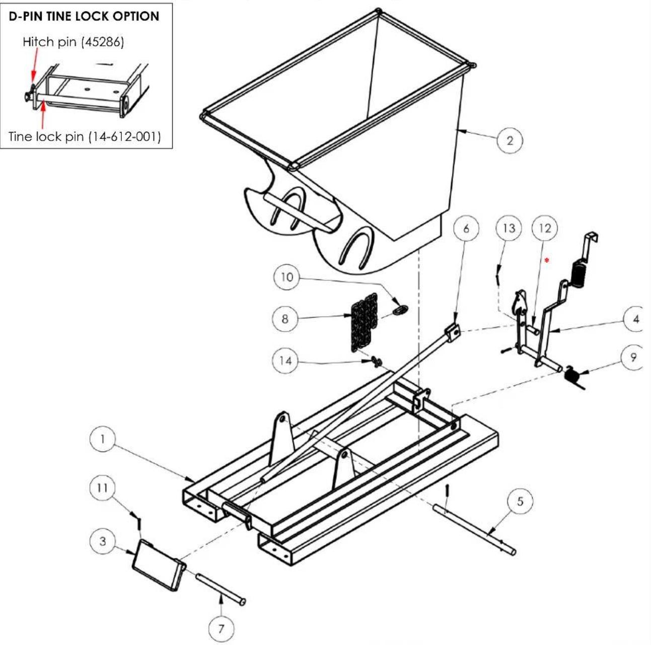
| Item | Part no. | Description | Qty. | Item | Part no. | Description | Qty. |
| 1 | 37-514-007 | Frame, weldment, base | 1 | 8 | 99-145-037 | 5/16" chain 36" long | 1 |
| 2 | 37-545-04137-545-011 | Weldment, chute:D-25-LDD-25-MD & D-25-HD | 11 | 9 | 37-146-005 | Spring, torsion, hopper release | 1 |
| 3 | 37-037-040 | Bumper release for D-hoppers | 1 | 10 | 99-145-053 | 5/16" quick link | 1 |
| 4 | 37-537-021 | Weldment, lock, release, lever assembly | 1 | 11 | 65127 | Cotter pin, zinc-plated, 3/16" x 2" | 3 |
| 5 | 37-612-005 | Subassembly, pin, main connection pin | 1 | 12 | 28-112-043 | Pin, 3/4" x 2" retaining clevis | 1 |
| 6 | 37-537-007 | Release lever rod weldment | 1 | 13 | 65080 | Extended prong cotter pin, zinc finish, 1/8" x 2" | 1 |
| 7 | 37-112-006 | Pin, bumper plate | 1 | 14 | 99-145-084 | Lap link | 1 |
D-50 series hoppers exploded parts diagram & bill of materials

| Item | Part no. | Description | Qty. | Item | Part no. | Description | Qty. |
| 1 | 37-514-007 | Frame, weldment, base | 1 | 8 | 99-145-037 | 5/16" chain 36" long | 1 |
| 2 | 37-545-043 | Weldment, chute: D-50-LD | 1 | 9 | 37-146-005 | Spring, torsion, hopper release | 1 |
| 37-545-012 | D-50-MD & D-50-HD | 1 | |||||
| 3 | 37-037-040 | Bumper release for D-hoppers | 1 | 10 | 99-145-053 | 5/16" quick link | 1 |
| 4 | 37-537-021 | Weldment, lock, release, lever assembly | 1 | 11 | 99-145-084 | Lap link | 1 |
| 5 | 37-612-005 | Subassembly, pin, main connection pin | 1 | 12 | 65127 | Cotter pin, zinc-plated, 3/16" x 2" | 3 |
| 6 | 37-537-007 | Release lever rod weldment | 1 | 13 | 28-112-043 | Pin, 3/4" x 2" retaining clevis | 1 |
| 7 | 37-112-006 | Pin, bumper plate | 1 | 14 | 65080 | Extended prong cotter pin, zinc finish, 1/8" x 2" | 1 |
D-75 series hoppers exploded parts diagram & bill of materials

| Item | Part no. | Description | Qty. | Item | Part no. | Description | Qty. |
| 1 | 37-514-008 | Frame, weldment, base | 1 | 8 | 99-145-084 | Lap link | 1 |
| 2 | 37-545-05037-545-013 | Chute weldment:D-75-LDD-75-MD & D-75-HD | 11 | 9 | 37-146-005 | Spring, torsion, hopper release | 1 |
| 3 | 37-037-040 | Bumper release for D-hoppers | 1 | 10 | 99-145-053 | 5/16" quick link | 1 |
| 4 | 37-537-021 | Weldment, lock, release, lever assembly | 1 | 11 | 99-145-037 | 5/16" chain 36" long | 1 |
| 5 | 37-612-005 | Subassembly, pin, main connection pin | 1 | 12 | 65127 | Cotter pin, zinc plated, 3/16" x 2" | 3 |
| 6 | 37-537-006 | Release lever rod weldment | 1 | 13 | 28-112-043 | Pin, 3/4" x 2" long retaining clevis | 1 |
| 7 | 37-112-006 | Pin, bumper plate | 1 | 14 | 65080 | Extended prong cotter pin, zinc finish, 1/8" x 2" | 1 |
D-100 series hoppers exploded parts diagram & bill of materials

*37-154-044 RELEASE HANDLE AND CABLE REPLACEMENT KIT

| Item | Part no. | Description | Qty. |
| 1 | 37-025-002 | HANDLE, CHUTE RELEASE | 1 |
| 2 | 37-145-001 | SPECIALTY HARDWARE CABLE | 1 |
| 3 | 43383 | SWAGE SLEEVE ∅1/8" X 5/8" LONG | 1 |
| 4 | 43403 | 1/4" WIRE CLAMP | 2 |
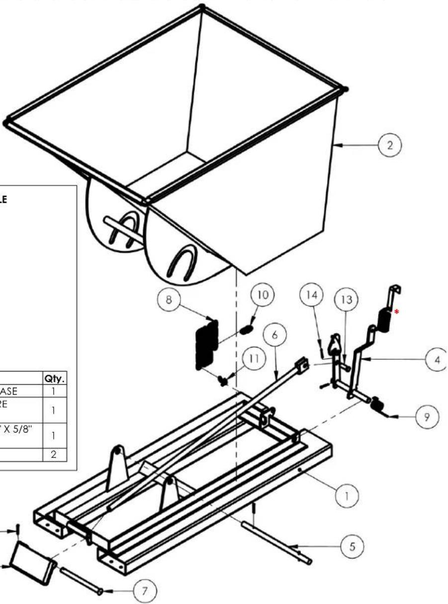
| Item | Part no. | Description | Qty. | Item | Part no. | Description | Qty. |
| 1 | 37-514-008 | Frame, weldment, base | 1 | 8 | 99-145-037 | 5/16" chain 36" long | 1 |
| 2 | 37-545-02237-545-04537-545-014 | Chute, weldment:D-100-LDD-100-MDD-100-HD | 1 | 9 | 37-146-005 | Spring, torsion, hopper release | 1 |
| 3 | 37-037-040 | Bumper release for D-hoppers | 1 | 10 | 99-145-053 | 5/16" quick link | 1 |
| 4 | 37-537-021 | Weldment, lock, release, lever assembly | 1 | 11 | 99-145-084 | Lap link | 1 |
| 5 | 37-612-005 | Subassembly, pin, main connection pin | 1 | 12 | 65127 | Cotter pin, zinc plated, 3/16" x 2" | 3 |
| 6 | 37-537-006 | Release lever rod weldment | 1 | 13 | 28-112-043 | Pin, 3/4" x 2" long retaining clevis | 1 |
| 7 | 37-112-006 | Pin, bumper plate | 1 | 14 | 65080 | Extended prong cotter pin, zinc finish, 1/8" x 2" | 1 |
D-150 series hoppers exploded parts diagram & bill of materials

| Item | Part no. | Description | Qty. | Item | Part no. | Description | Qty. |
| 1 | 37-514-004 | Frame, weldment, base | 1 | 8 | 99-145-037 | 5/16" chain 36" long | 1 |
| 2 | 37-545-04637-545-015 | Weldment, chute:D-150-LDD-150-MD & D-150-HD | 11 | 9 | 37-146-005 | Spring, torsion, hopper, release | 1 |
| 3 | 37-037-040 | Bumper release for D-hoppers | 1 | 10 | 99-145-053 | 5/16" quick link | 1 |
| 4 | 37-537-020 | Weldment, lock, release, lever assembly, hopper | 1 | 11 | 99-145-084 | Lap link | 1 |
| 5 | 37-612-006 | Subassembly, pin, main connection pin | 1 | 12 | 65127 | Cotter pin, zinc plated, 3/16" x 2" | 3 |
| 6 | 37-537-006 | Release lever rod weldment | 1 | 13 | 28-112-043 | Pin, 3/4" x 2" retaining clevis | 1 |
| 7 | 37-112-006 | Pin, bumper plate | 1 | 14 | 65080 | Extended prong cotter pin, zinc finish, 1/8" x 2" | 1 |
D-200 series hoppers exploded parts diagram & bill of materials
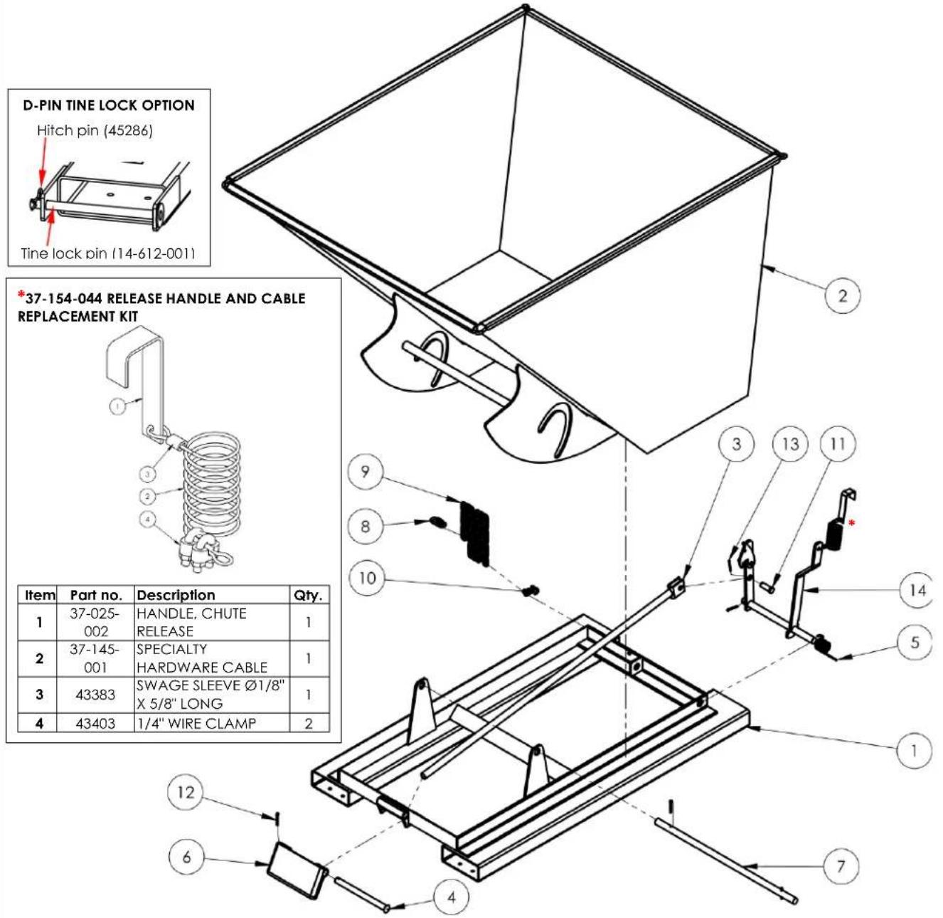
| Item | Part no. | Description | Qty. | Item | Part no. | Description | Qty. |
| 1 | 37-514-004 | Frame, weldment, base | 1 | 8 | 99-145-053 | 5/16" quick link | 1 |
| 2 | 37-545-025 | Weldment, chute: D-200-LD | 1 | 9 | 99-145-037 | 5/16" chain 36" long | 1 |
| 37-545-026 | D-200-MD | 1 | |||||
| 37-545-007 | D-200-HD | 1 | |||||
| 3 | 37-537-006 | Release lever rod assembly | 1 | 10 | 99-145-084 | Lap link | 1 |
| 4 | 37-112-006 | Pin, bumper plate | 1 | 11 | 28-112-043 | Pin, 3/4" × 2" long retaining clevis | 1 |
| 5 | 37-146-005 | Spring, torsion, hopper release | 1 | 12 | 65127 | Cotter pin, zinc plated | 3 |
| 6 | 37-037-040 | Bumper release for D-hoppers | 1 | 13 | 65080 | Extended prong cotter pin, zinc finish, 1/8" × 2" | 1 |
| 7 | 37-612-006 | Subassembly, pin, main connection pin | 1 | 14 | 37-537-020 | Weldment, lock, release, lever assembly, hopper | 1 |
D-250 series hoppers exploded parts diagram & bill of materials

| Item | Part no. | Description | Qty. | Item | Part no. | Description | Qty. |
| 1 | 37-514-004 | Frame, weldment, base | 1 | 8 | 99-145-037 | 5/16" chain 36" long | 1 |
| 2 | 37-545-016 | Weldment, chute | 1 | 9 | 37-146-005 | Spring torsion, hopper release | 1 |
| 3 | 37-037-040 | Bumper release for D-hoppers | 1 | 10 | 99-145-053 | 5/16" quick link | 1 |
| 4 | 37-537-020 | Weldment, lock, release, lever assembly, hopper | 1 | 11 | 99-145-084 | Lap link | 1 |
| 5 | 37-612-006 | Subassembly, pin, main connection pin | 1 | 12 | 65127 | Cotter pin, zinc plated, 3/16" × 2" | 3 |
| 6 | 37-537-006 | Release lever rod weldment | 1 | 13 | 28-112-043 | Pin, 3/4" × 2" long retaining clevis | 1 |
| 7 | 37-112-006 | Pin, bumper plate | 1 | 14 | 65080 | Extended prong cotter pin, zinc finish, 1/8" × 2" | 1 |
D-300 series hoppers exploded parts diagram & bill of materials

| Item | Part no. | Description | Qty. | Item | Part no. | Description | Qty. |
| 1 | 37-514-004 | Frame, weldment, base | 1 | 8 | 99-145-037 | 5/16 " chain 36" long | 1 |
| 2 | 37-545-006 | Weldment, chute | 1 | 9 | 37-146-005 | Spring, torsion, hopper release | 1 |
| 3 | 37-037-040 | Bumper release for D-hoppers | 1 | 10 | 99-145-053 | 5/16 " quick link | 1 |
| 4 | 37-537-020 | Weldment, lock, release, lever assembly, hopper | 1 | 11 | 99-145-084 | Lap link | 1 |
| 5 | 37-612-006 | Subassembly, pin, main connection pin | 1 | 12 | 65127 | Cotter pin, zinc plated, 3/16 " x 2" | 3 |
| 6 | 37-537-006 | Release lever rod weldment | 1 | 13 | 28-112-043 | Pin, 3/4 " x 2" long retaining clevis | 1 |
| 7 | 37-112-006 | Pin, bumper plate | 1 | 14 | 65080 | Extended prong cotter pin, zinc finish, 1/8 " x 2" | 1 |
D-300-HD-NA, D-350-HD, D-400-HD and D-500-HD series hoppers exploded parts diagram & bill of materials
*37-154-044 RELEASE HANDLE AND CABLE REPLACEMENT KIT

| Item | Part no. | Description | Qty. |
| 1 | 37-025-002 | HANDLE,CHUTERELEASE | 1 |
| 2 | 37-145-001 | SPECIALTYHARDWARECABLE | 1 |
| 3 | 43383 | SWAGESLEEVE ∅1/8"X 5/8" LONG | 1 |
| 4 | 43403 | 1/4" WIRECLAMP | 2 |
D-PIN TINE LOCK OPTION

Tine lock pin (14-612-001)

| Item | Part no. | Description | Qty. | Item | Part no. | Description | Qty. |
| 1 | 37-514-081 | Weldment, frame, base | 1 | 9 | 37-112-006 | Pin, bumper plate | 1 |
| 2 | 32415 | 5/16" - 18 × 1/2" HWH thread cutting screw, type F, zinc | 2 | 10 | 99-145-053 | 5/16" quick link | 1 |
| 3 | 37-545-106 | Weldment, chute: D-300-HD-NA | 1 | 11 | 65125 | Cotter pin, zinc plated, 3/16" x 11/2" | 1 |
| 37-545-104 | D-350-HD | ||||||
| 37-545-090 | D-400-HD | ||||||
| 37-545-088 | D-500-HD | ||||||
| 4 | 37-612-004 | Weldment, pin, main, connection pin | 2 | 12 | 99-145-084 | Lap link | 1 |
| 5 | 37-537-019 | Weldment, release lever rod | 1 | 13 | 65127 | Cotter pin, zinc plated, 3/16" x 2" | 1 |
| 6 | 37-537-020 | Weldment, lock, release, lever assembly, hopper | 1 | 14 | 37-037-040 | Bumper release for D-hoppers | 1 |
| 7 | 28-112-043 | Pin, 3/4" x 2" long retaining clevis | 1 | 15 | 99-145-037 | 5/16" chain 36" long | 1 |
| 8 | 37-146-005 | Spring, torsion, hopper release | 1 | 16 | 65080 | Extended prong cotter pin, zinc finish, 1/8" x 2" | 1 |
SIGNAL WORDS
SIGNAL WORDS in this manual draw the reader's attention to important safety-related messages.

DANGER

WARNING

CAUTION
NOTICE
Identifies a hazardous situation which, if not avoided, WILL result in DEATH or SERIOUS INJURY. Use of this signal word is limited to the most extreme situations.
Identifies a hazardous situation which, if not avoided, COULD result in DEATH or SERIOUS INJURY.
Indicates a hazardous situation which, if not avoided, COULD result in MINOR or MODERATE injury.
Identifies practices likely to result in product/property damage, such as operation that might damage the product.
SAFETY INSTRUCTIONS
Vestil strives to identify all foreseeable hazards associated with the use of its products, but no manual can address every conceivable risk. Prevent injury by applying sound judgment whenever using this device. Acquire a copy of the latest version of ITSDF/ANSI B56.1 ("B56.1" or the "Standard"). The Standard is freely downloadable on www.ITSDF.org. Apply all portions of Part II "For the User" about the use of attachments and removable attachments. The following instructions complement provisions of B56.1.
WARNING
Risk of serious personal injuries or death! Always apply the following safety instructions.
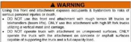
- Before this product may be used, U.S. Occupational Safety and Health Administration rule 1910.178(a)(4) and (a)(5) require that the owner/user: 1) Obtain written approval from the manufacturer(s) of all forklifts [or from a professional engineer] that will be used with the hopper; 2) Change capacity, operation, & maintenance instruction plates, tags, or decals accordingly; AND 3) Mark the forklift truck to identify the beam and show the approximate weight of the truck and beam combination at maximum elevation with load laterally centered. Requirements are published at https://www.osha.gov/pls/oshaweb/owadisp.show_document?p_table=STANDARDS&p_id=9828
- DO NOT use this hopper with rough terrain lift trucks or telehandlers (boom trucks). ONLY use this hopper with high lift fork trucks utilizing a vertical mast and carriage. DO NOT mount the hopper on stackers or manually propelled lift trucks. - DO NOT operate the truck carrying this hopper on unimproved surfaces. Only operate on concrete or asphalt surfaces. - Read & understand this entire manual before using, inspecting, or servicing the hopper. - Inspect the hopper as directed in the INSPECTIONS & MAINTENANCE section on p. 16. DO NOT use it unless it is in SATISFACTORY CONDITION. See RECORD OF SATISFACTORY CONDITION on p. 16. - DO NOT use the hopper if the carriage chain is damaged or missing. DO NOT lift the hopper until it is securely connected to the carriage of the fork truck with the carriage chain.
- DO NOT fill the hopper beyond its maximum rated load. See SPECIFICATIONS tables on page 2.
- NO ONE should travel under the hopper at any time while it is elevated.
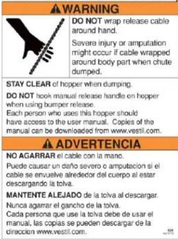
- NEVER wrap the release cable around your hand, fingers, or any other part of your body!
- Hoppers with lifting lugs can be lifted with overhead hoists and cranes. DO NOT lift a hopper unless the chute is securely latched to the frame.
- DO NOT allow people to ride on or in the hopper.
- DO NOT use the hopper if any label is unreadable or missing. Apply replacement labels before returning the hopper to service. See LABELING DIAGRAM on p. 17.
- ALWAYS apply proper lift truck operation techniques learned during your training program. Before raising the hopper from the floor, tilt the (forklift) mast toward the cab of the truck to ensure that the hopper will not slide off of the forks.
- DO NOT modify the hopper without first obtaining written approval from Vestil! Unapproved modifications might make the hopper unsafe & automatically void the LIMITED WARRANTY on p. 12.
- DO NOT dump the hopper UNLESS everyone in the vicinity is a safe distance from the dumping site.
- DO NOT dump the hopper unless the forklift is on an even, level surface.
- DO NOT exceed the load ratings or fill the hopper above the side walls. Injury to personnel or permanent damage to the equipment could result from overloading.
NOTE: This self-dumping hopper helps to prevent non-compliance with US Federal OSHA rule 1910.178(m)(5). Subpart 1910.178(m)(5)(iii) requires operators of powered trucks to fully lower the "load engaging means" [forks], neutralize truck controls, and set brakes whenever they dismount a lift truck &remain within 25ft of it. Operators can remain at the controls of their trucks throughout the dumping process while using this hopper.
NATIONAL STANDARDS
US OSHA Rule 1910.178 (29 CFR 1910.178; the "Rule") classifies this device as a "front-end attachment" whenever it is mounted on a lift truck. The Rule incorporates American National Standard ANSI/ITSDF B56.1 (the "Standard"). The Standard is published by the Industrial Truck Standards Development Foundation on its website (www.itsdf.org) where it is freely downloadable at http://www.itsdf.org/cue/b56-standards.html.
Before putting this device into service, acquire a copy of the Standard. Apply all relevant parts of Part II: For the User. If instructions provided in this manual apparently conflict with the Standard, then apply the instructions in the Standard. Vestil requests that you immediately bring to its attention any conflicts you discover by contacting its TECHNICAL SERVICE department. Contact information is provided on the cover page of this manual.
USING THE HOPPER
Because this product is self-dumping, it helps to prevent non-compliance with US Federal OSHA rule 1910.178(m)(5). In particular, subpart 1910.178(m)(5)(iii), requires operators of powered trucks to fully lower the "load engaging means" (forks), neutralize truck controls, and set brakes whenever they dismount a lift truck and remain within 25ft of it. By allowing lift truck operators to remain at the controls of their trucks throughout the dumping process, there is no need to dismount the lift truck while dumping the hopper.
Confirm that the hopper chute is latched to the base frame (i.e. NOT released and cannot rotate) before filling the chute with refuse. Standard self-dumping hoppers are suitable for use indoors and outdoors and in most industrial and commercial settings. They are intended to be used with rider forklift trucks as a means for dumping non-hazardous refuse into larger trash receptacles. The chute rotates through a 70° dump angle. D-series hoppers can be dumped in 2 ways: 1) Manually—by pulling the release cable; and 2) Remotely—by pressing the bumper plate against an object.
Step 1: Drive the lift truck forward and insert the forks into the fork tubes. Drive forward until either: 1) the tips of the forks begin to stick out of the ends of the tubes; or 2) if the forks are not long enough to extend all the way through the tubes, drive forward as far as possible. If your hopper includes tine lock option D-PIN, drive as far forward as possible. Then, insert the tine lock pins (14-612-001 through the pin holes in the pin brackets at the end of each fork tube. Secure the tine lock pins in place with hitch pins (45286).
Step 2: Wrap the chain around part of the fork carriage. Connect the quick link at the end of the chain to a link in the chain with as little slack as possible.
⚠ WARNING DO NOT wrap the release cable around any part of your body, especially your hands. DO NOT attach the handle to your clothing. If you do and the chute is released, you might be seriously injured.
Step 3: If you will release the chute manually by pulling the release handle, store the handle within reach of the forklift operator, for example by hooking it to the frame of the cab. Make sure that there is plenty of slack in the cable to avoid accidentally releasing/dumping the chute.
NOTE: If you will use the bumper plate mechanism to dump the chute, attach the handle to the hopper frame. Do not hook the handle to the chute! It could be torn from the cable when the chute is dumped.
Step 4: Drive the forklift to the trash receptacle. Before raising the hopper, unlock the latch lever by pulling the finger tab until the lock disengages the latch bar. See diagrams with Step 5.
Step 5: Raise the forks and tilt the forklift mast backwards (towards the cab). Tilting the mast backwards makes it easier to release the latch. The hopper can now be dumped manually or remotely:
A) Manually: elevate the entire hopper above the side wall of the dumpster. See diagram A. Tilt the mast forward slightly and pull the release cable.
NOTE: NEVER wrap the release cable around any part of your body, particularly fingers, hands, and arms.
B) Remotely: elevate the hopper so that the bumper plate can contact the side of the dumpster at or near the top. See diagram B. Drive the forklift toward the dumpster and press the bumper plate against the top of the side wall. Tilt the mast forward slightly, if necessary, to dump the chute.


Step 6: Return the chute to the latched position. Tilt the forklift mast toward the cab and back away from the dumpster. The hopper should automatically return to the latched position. Confirm that the chute is latched to the base by tilting the mast forward (away from the cab). The chute should not dump. If the chute will not latch by tilting the mast backwards, set the hopper on the ground and manually latch the chute to the frame. Press down on the rear wall of the chute until the latch lever engages the latch bar. Apply the lock.
RECORD OF SATISFACTORY CONDITION
After receiving the unit and before using it for the first time, create a record that describes the appearance and operation of the hopper. Thoroughly photograph the unit from multiple angles. Take close range photographs of the labels, release mechanisms, safety chain—particularly at each end, pivot points, and pivot point hardware. Mount the hopper of the forks of your forklift and apply the safety chain. Elevate the hopper and release the chute. Record your observations about how the unit looks and sounds as the chute rotates. Lower the unit and secure the chute to the frame. Record your observations. This written record establishes satisfactory condition. Compare the results of all inspections to this record to determine whether a component is in satisfactory condition or requires repair or replacement. If issues are discovered during an inspection, DO NOT use the hopper until it is restored to satisfactory condition. Purely cosmetic changes, like damaged surface coating (paint or powdercoat) are not changes from satisfactory condition. However, touchup paint should be applied wherever the finish is damaged as soon as damage occurs.
INSPECTIONS & MAINTENANCE
Inspections and repairs should only be performed by qualified persons. Compare the results of each inspection to the RECORD OF SATISFACTORY CONDITION (the "RECORD"). Do not use the hopper unless all parts are in satisfactory condition. Replace parts that are not in satisfactory condition before using the hopper again. DON'T GUESS! If you have any questions about the condition of your hopper, speak with TECHNICAL SERVICE personnel. The phone number is provided on the cover page of this manual. Never make temporary repairs of damaged or missing parts. Only use manufacturer-approved replacement parts.
Step 1: At least once per month, tag the hopper "Out of Service."
Step 2: Inspect the hopper. Replace any component that is not in satisfactory condition.
1) Pivot points: Check for excessive wear, warping, or other significant damage to pivot pins, cotter pins, and pin receivers.
2) Hopper chute and base frame: Examine the structures for damage, deformation, and corroded or excessively rusted regions. Remove rust with a steel bristle brush and apply touch-up paint to exposed metal.
3) Hardware (bolts, nuts, pins, cotter pins, retaining rings): Inspect hardware for looseness and severe wear. Tighten loose connections and replace all damaged hardware.
4) Casters (if hopper is equipped with caster kit): Check for looseness, excessive wear, and damage to the caster wheels, caster bearings, mounting brackets, and mounting hardware.
5) Release mechanism: The torsion spring should cause the latch lever to automatically recoil and the lever should firmly contact the release lock bar. Check the release cable for frays, thinning, corrosion, and bird-caging. Replacement kit 37-154-044 (shown in exploded views on p. 5-13) includes a handle, cable, and 2 wire clamps (1/4"). To install a replacement handle and cable kit, loosen the nuts of both wire clamps and feed the free end of the cable through the clamps. Insert the end of the cable through the hole in the manual chute release lever (see diagram on p. 15). Feed the cable back through the clamps and tighten all 4 nuts.
6) Pivot points: Listen for unusual sounds. Watch for irregular movements. Remove dirt and debris from areas that could affect the dumping motion.
7) Carriage chain: Examine the chain, the attachment to the base frame, & the quick links for damage.
8) Labels: All labels should be present in the locations shown in the Labeling Diagram on p. 17.
Step 3: Make all adjustments, replacements, and repairs necessary to restore satisfactory condition.
WARNING
DO NOT modify the hopper in any way without first obtaining written approval from Vestil.
Modifications automatically void the Limited Warranty and might make the hopper unsafe to use. Modifications are changes that alter the hopper, like or removing or bending a component.
Step 4: Make a dated record of all repairs and replacements.
LABELING DIAGRAM
The unit should be labeled as shown in the diagram. Label content and location are subject to change so your product might not be labeled exactly as shown. Compare this diagram to your Record of Satisfactory Condition. Replace all labels that are damaged, missing, or not easily readable (e.g. faded). Order replacement labels by contacting the Replacement Parts Department online at https://www.vestil.com/page-parts-request.php. Alternatively, you may request replacement parts and/or service by calling (260) 665-7586 and asking the operator to connect you to the Parts Department.

B: Label 1037 (CAUTION on side of hopper)

C: Label 1023 (CAUTION on side of hopper)

D: Label 220 (both sides)

E: Label 208 (both fork tubes)

F: Label 995

G: Model specific label (see tables)

A: Label 620 (left side in-line with manual release handle)
H: Label 1210
I: Label 1049

| Model | Label | Model | Label |
| D-25-LD | 549 | D-75-LD | 549 |
| D-25-MD | 549 | D-75-MD | 549 |
| D-25-HD | 549 | D-75-HD | 592 |
| D-33-LD | 549 | D-100-LD | 630 |
| D-33-MD | 549 | D-100-MD | 1050 |
| D-33-HD | 591 | D-100-HD | 644 |
| D-50-LD | 549 | D-150-LD | 549 |
| D-50-MD | 549 | D-150-MD | 549 |
| D-50-HD | 542 | D-150-HD | 544 |
| Model | Label |
| D-200-LD | 540 |
| D-200-MD | 541 |
| D-200-HD | 545 |
| D-250-LD | 549 |
| D-250-MD | 549 |
| D-250-HD | 593 |
| D-300-LD | 549 |
| D-300-MD | 631 |
| D-300-HD | 546 |
| D-300-HD-NA | 549 |
| D-350-HD | 549 |
| D-400-HD | 549 |
| D-500-HD | 549 |
LIMITED WARRANTY
Vestil Manufacturing Company ("Vestil") warrants this product to be free of defects in material and workmanship during the warranty period. Our warranty obligation is to provide a replacement for a defective, original part covered by the warranty after we receive a proper request from the Warrantee (you) for warranty service.
Who may request service?
Only a warrantee may request service. You are a warrantee if you purchased the product from Vestil or from an authorized distributor AND Vestil has been fully paid.
Definition of "original part"?
An original part is a part used to make the product as shipped to the Warrantee.
What is a "proper request"?
A request for warranty service is proper if Vestil receives: 1) a photocopy of the Customer Invoice that displays the shipping date; AND 2) a written request for warranty service including your name and phone number. Send requests by one of the following methods:
| US Mail | Fax | |
| Vestil Manufacturing Company | (260) 665-1339 | info@vestil.com |
| 2999 North Wayne Street, PO Box 507 | Phone | Enter "Warranty service request" in the subject field. |
| Angola, IN 46703 | (260) 665-7586 |
In the written request, list the parts believed to be defective and include the address where replacements should be delivered. After Vestil receives your request for warranty service, an authorized representative will contact you to determine whether your claim is covered by the warranty. Before providing warranty service, Vestil will require you to send the entire product, or just the defective part (or parts), to its facility in Angola, IN.
What is covered under the warranty?
The warranty covers defects in the following original, dynamic parts: motors, hydraulic pumps, motor controllers, and cylinders. It also covers defects in original parts that wear under normal usage conditions ("wearing parts"), such as bearings, hoses, wheels, seals, brushes, and batteries.
How long is the warranty period?
The warranty period for original dynamic components is 90 days. For wearing parts, the warranty period is 90 days. Both warranty periods begin on the date Vestil ships the product to the Warrantee. If the product was purchased from an authorized distributor, the periods begin when the distributor ships the product. Vestil may, at its sole discretion, extend a warranty period for products shipped from authorized distributors by up to 30 days to account for shipping time.
If a defective part is covered by the warranty, what will Vestil do to correct the problem?
Vestil will provide an appropriate replacement for any covered part. An authorized representative of Vestil will contact you to discuss your claim.
What is not covered by the warranty?
The Warrantee (you) is responsible for paying labor costs and freight costs to return the product to Vestil for warranty service.
Events that automatically void this Limited Warranty.
- Misuse;
- Negligent assembly, installation, operation or repair;
• Installation/use in corrosive environments; - Inadequate or improper maintenance;
• Damage sustained during shipping;
• Collisions or other accidents that damage the product; - Unauthorized modifications: Do not modify the product IN ANY WAY without first receiving written authorization from Vestil.
Do any other warranties apply to the product?
Vestil Manufacturing Co. makes no other express warranties. All implied warranties are disclaimed to the extent allowed by law. Any implied warranty not disclaimed is limited in scope to the terms of this Limited Warranty. Vestil makes no warranty or representation that this product complies with any state or local design, performance, or safety code or standard. Noncompliance with any such code or standard is not a defect in material or workmanship.




- VESTIL MANUFACTURING CO
- RECEIVING INSTRUCTIONS
- TECHNICAL SERVICE & REPLACEMENT PARTS
- ELECTRONIC COPIES OF INSTRUCTION MANUALS
- SPECIFICATIONS
- D-300-HD-NA, D-350-HD, D-400-HD AND D-500-HD SERIES HOPPERS EXPLODED PARTS DIAGRAM & BILL OF MATERIALS
- SIGNAL WORDS
- SAFETY INSTRUCTIONS
- WARNING
- NATIONAL STANDARDS
- USING THE HOPPER
- RECORD OF SATISFACTORY CONDITION
- INSPECTIONS & MAINTENANCE
- LABELING DIAGRAM
- LIMITED WARRANTY
- WHO MAY REQUEST SERVICE
- DEFINITION OF "ORIGINAL PART
- WHAT IS A "PROPER REQUEST
- WHAT IS COVERED UNDER THE WARRANTY
- HOW LONG IS THE WARRANTY PERIOD
- IF A DEFECTIVE PART IS COVERED BY THE WARRANTY, WHAT WILL VESTIL DO TO CORRECT THE PROBLEM
- WHAT IS NOT COVERED BY THE WARRANTY
- EVENTS THAT AUTOMATICALLY VOID THIS LIMITED WARRANTY
- DO ANY OTHER WARRANTIES APPLY TO THE PRODUCT
Brand : Vestil
Model : D-250-HD
Category : Trémie industrielle