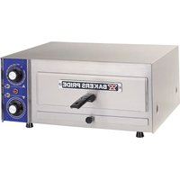
PX-14 - Pizza oven Bakers Pride - Free user manual and instructions
Find the device manual for free PX-14 Bakers Pride in PDF.


| Product Type | Commercial Pizza Oven |
| Brand | Bakers Pride |
| Model | PX-14 |
| Category | Countertop Electric Pizza Oven |
| Dimensions (W x D x H) | 38 in x 33 in x 18 in (96.5 cm x 83.8 cm x 45.7 cm) |
| Weight | 195 lbs (88.5 kg) |
| Power Source | Electric |
| Voltage | 208/240V, Single Phase |
| Wattage | 5,000 W |
| Temperature Range | 200°F to 600°F (93°C to 316°C) |
| Cooking Surface Material | Refractory Ceramic Deck |
| Number of Decks | 1 |
| Heating Type | Top and Bottom Elements (Thermostatically Controlled) |
| Control Type | Manual Thermostat with On/Off Switch |
| Safety Features | Cool-Touch Handle, Automatic Safety Shutoff, Pilot Light Indicator |
| Cleaning | Stainless Steel Exterior, Removable Crumb Tray, Smooth Deck Surface |
| Warranty | 1 Year Limited Parts and Labor |
| Included Accessories | Pizza Peel, Instruction Manual |
| Certifications | ETL, NSF |
Frequently Asked Questions - PX-14 Bakers Pride
User questions about PX-14 Bakers Pride
0 question about this device. Answer the ones you know or ask your own.
Ask a new question about this device
Download the instructions for your Pizza oven in PDF format for free! Find your manual PX-14 - Bakers Pride and take your electronic device back in hand. On this page are published all the documents necessary for the use of your device. PX-14 by Bakers Pride.
USER MANUAL PX-14 Bakers Pride
OPERATION MANUAL
HEARTHBAKE SERIES COUNTERTOP DECK OVENS
SERIES: DP, BK, PX, & P-18, 22, 24, 44, 46, 48


BUILT BY CRAFTSMEN. TESTED BY TIME.
COUNTERTOP ELETRIC OVENS
Series:
PX-14, PX-16, P-18, BK-18, P-22S, P-22BL, P-24S, P-44S, P-44BL, P-46S, P-48S, DP-2
Bakers Pride Oven Company, LLC is a wholly owned subsidiary of Standex International Corporation.
All gas operated Bakers Pride ® ovens are intended for use with the type of gas specified on the rating plate and for installation will be in accordance with National Fuel Gas Code ANSI Z223.1 (latest edition).
WARNING
FOR YOUR SAFETY: Do not store or use gasoline or other flammable vapors or liquids in the vicinity of this or any other appliance.
CAUTION
Improper installation, adjustment, alteration, service or maintenance can cause property damage, injury or death. Read the installation, operating and maintenance instructions thoroughly before installing or servicing this equipment.
NOTICE
Only Pizza or Bread can have direct contact with Fibrament decks. All other food products must be placed in a pan or container to avoid direct contact with ceramic decks.
Please retain this manual for future references.
This equipment is design engineered for commercial use only.

TABLE OF CONTENTS
| ITEM | PAGE |
| SAFETY PRECAUTIONS 1 | |
| INSTALLATION INSTRUCTIONS 2 | |
| Minimum Clearance for Installation 2 | |
| Location | 2 |
| Electrical Connections 2 | |
| Requirements for Installation 2 | |
| Initial Start Up 2 | |
| OPERATING INSTRUCTIONS 3 | |
| General Baking 3 | |
| General Baking Tips 3 | |
| Special Features 4 | |
| Cleaning | 4 |
| Service and Trouble Shooting 4 | |
| Installation of Decks 5 | |
WIRING DIAGRAMS & SCHEMATICS 6
| P Series - 2 Chamber - 1 Ph, 2 W or 3 Ph, 3 W (Wiring Diagram) | 6 |
| P Series - 2 Chamber - 3 Ph, 4 W - Star (Wiring Diagram) | 7 |
| ITEM | PAGE |
| P Series - 1 Chamber - 3 Ph, 4 W - Star (Wiring Diagram) | 8 |
| P Series - 1 Chamber - 1 Ph, 2 W or 3 Ph, 3 W(Wiring Diagram) | 9 |
| P Series Countertop Ovens - 2 Chamber (Schematic) | 10 |
| P Series Counter Top Ovens - 1 Chamber (Schematic) | 10 |
| PX-14 & PX-16 (Wiring Diagram & Tables) | 11 |
| EXPLODED VIEWS & PARTS LISTS | |
| PX -14, PX-16 (New Style) | 12 |
| PX -14, PX-16 (Old Style) | 13 |
| P18-S & BK18 | 14 |
| P-22BL, P-22S & P-24S | 16 |
| P-44S, P-44BL & P-48S | 18 |
| DP-2 | 20 |
| WARRANTY | 22 |
SAFETY PRECAUTIONS
DANGER
This symbol warns of imminent hazard which will result in serious injury or death.
WARNING
This symbol refers to a potential hazard or unsafe practice, which could result in serious injury or death.
CAUTION
This symbol refers to a potential hazard or unsafe practice, which may result in or moderate injury or product or property damage.
NOTICE
This symbol refers to information that needs special attention or must be fully understood even though not dangerous.
INSTALLATION INSTRUCTIONS
Minimum Clearance for Installation
From combustible or non-combustible construction: Right side, Left side and Back: 3" (76mm)
Location
Due to the heat a countertop oven may produce, it must be placed on a non-combustible surface. Do not store combustible materials on top of any oven.
Electrical Connections
Suitable means, which will disconnect all ungrounded conductors of the circuit simultaneously, must be provided by the installer.
Make sure electrical supply corresponds with that specified on the rating plate located in the rear of the oven.
When installed, the unit must be connected by an earthing cable to all other units within the complete installation and thence to an independent earth connection.
Use copper conductors only, rated at 90° C.
If a line cord is used for the installation of the unit in Europe, it should be a minimum of H07RN-F type conforming to EN60 335-1 and/or local codes.
Use minimum conductor size as below:
- For models PX-14, PX-16, P-18, BK-18 and P-24S: 14 Gauge (1.5mm) for 220-240V, single phase supply.
- For models P-22S, P-22BL, P-44S, P-44BL, P-46S, P-48S and DP-2: 10 Gauge (2.5mm) for 220-240/380-415V, 3 phase supply.
Requirements For Installation
For portable units (Model PX-14 and PX-16) there are no special requirements.
For shipping purposes the optional 4" (100mm) legs are not mounted. For mounting legs, follow steps a - g.
a. Remove the outer shipping carton and paper and place the oven on the floor or other flat surface.
b. Remove legs, baking decks and any other materials from inside the unit.
c. With sufficient help, tilt the unit back far enough to mount the two front legs and tighten with an adjustable wrench.
d. After the front legs are tight, lift rear of unit approximately 5" (125mm) off the surface and block in position using wood or some other solid material. Now mount the two rear legs and tighten.
e. Using the proper lifting equipment, move the unit to its final location.
f. Adjust the bottom portion of legs to make level.
g. Slide baking decks into each shelf. (See Installation of Decks on Page 5.)
Initial Start Up
After the electrical connections have been made, the oven will need approximately 2 to 3 hours to burn off.
CAUTION
Overexposure to smoke or fumes may cause nausea and dizziness.
Initial heating of the oven may generate smoke or fumes and must be done in a well ventilated area.
For initial heating of the new oven, follow the steps below:
- Place the oven in a well ventilated area.
- Open the oven doors and remove any instructions or samples shipped within the unit. Make sure the oven cavity is empty and the baking decks are properly installed.
- With the oven doors open, turn the temperature knobs to 400° F (205° C) for one hour. Close the oven door. Increase the temperature to 500° F (260° C) for at least 1 1/2 hours.
This procedure will dry out the insulation and deck material and will help to insure optimum baking results thereafter.
OPERATING INSTRUCTIONS
NOTICE
Only Pizza or Bread can have direct contact with Fibrament decks. All other food products must be placed in a pan or container to avoid direct contact with ceramic decks.
General Baking
Models: P-18, BK-18, P-22S, P-22BL, P-24S, P-44S, P-44BL, P-46S, P-48S, PX-14 and PX-16
- Preheat the oven by setting the thermostat to the desired temperature. When the thermostat light goes out and has cycled three times, the oven is ready for use.
- These ovens have been designed to bake both fresh and frozen products. Frozen fruit pies should be taken directly from the freezer and placed into the oven. Cooking time will vary with the size of the pie, but under normal conditions a frozen pie should bake approximately in the same time as a fresh pie.
- These ovens work well for toasting, melting cheese, baking frozen entrees, roasting small meat items, etc.
- The temperature range for pizza baking is usually between 500° F (260° C) and 575° F (300° C) depending on the individual product.
- Allow the pizza to bake until the cheese bubbles and the bottoms are evenly brown. (Rotate if necessary)
- The design of the PX-14 and PX-16 is such that normal baking temperature may be too high for good results. Set the thermostat approximately 25° F (15°C) BELOW normal setting. Adjust temperature as needed.
- Do not keep the oven door open too long when loading since heat will escape, resulting in slower baking.
- When production requirements are low, keep the temperature low to prevent the bottoms from burning.
- As demand increases, temperature should be raised for faster recovery.
- Fresh dough generally requires a slightly lower baking temperature and longer bake time than defrosted pre-baked crusts.
General Baking Tips
- Pizza crusts should be fully defrosted before baking.
- Wet areas on the bottom of a pizza will cause them to stick to the deck. Avoid spills.
- For fresh dough pizza, flour or corn meal on the peel will prevent sticking and ease placement of the pizza on the deck.
- Increasing bake temperature during heavy production assists in maintaining temperature. After the rush is over, reduce temperature to prevent burning.
- Heavily topped pizzas require longer bake times at lower temperatures.
- Placing a screen under pizza will allow the top to cook without overcooking the bottom.
Frequently scrape and brush off decks to remove burned residue which can cause an off flavor to the product. Residue build-up can slow bake times. A deck scraper/brush specially designed for this available from Bakers Pride.
- Clean heavily soiled pizza decks by scraping down, brushing off, removing from oven, turning over and putting back. This procedure will burn off the decks and should be repeated every six months. DO NOT USE WATER TO CLEAN THE DECKS as this could cause the decks to crack.
- Using shiny pans or screens will produce products with light bottom color. We strongly suggest that all pans and screens be seasoned before use.
OPERATING INSTRUCTIONS
Special Features
- Timer: An electric timer is provided to give an audible, continuous signal at the end of a preset time up to 15 minutes (18 minutes with 50Hz supply) on pizza ovens, or 60 minutes (72 minutes with 50Hz supply) on bake ovens.
- Optional Electronic Timer: A Digital electronic 99 minute timer can be provided on all models to give an audible signal at the end of a pre-set time.
NOTICE
Timer does not control the oven.
- For PX-14 and PX-16 only: Individual switches are provided to turn off the top or the bottom heating element. This allows baking items that do not require direct top or bottom heat.
- For DP-2 only: Optional infinite control switches can be provided for fine balancing of top and bottom heat.
Cleaning
- Periodic cleaning is suggested to keep your oven in good shape.
CAUTION
Always Clean The Oven When It Is Cold.
- When cleaning stainless steel, always wipe in the direction of the grain. Scrapers, brushes and stainless steel cleaner can be ordered from Bakers Pride for this purpose.
- From time to time the spillage should be scraped out. For hard to clean spillage, the following is suggested
- Turn the thermostat up to the highest setting and let the oven run for 1/2 hour with the door closed.
- Allow the oven to cool down.
- Brush residue from the deck.
NOTICE
Do Not Use Water To Clean Decks. Cracking May Result.
- Stainless steel surfaces should be cleaned with Bakers Pride stainless steel cleaner.
Service and Troubleshooting
The ovens are designed to be as trouble free as possible. Keeping the oven clean is all that is normally required. All servicing should be performed by a factory authorized technician only.
However, if your oven stops operating, please check the following:
- Power supply cord is plugged into the supply receptacle.
- Power supply fuse/circuit breaker has not tripped.
If the oven still does not operate, take the following steps:
- Disconnect the power supply to the unit by removing the supply cord and/or turning off the main switch.
- Contact the factory, factory representative or an authorized service agency.
NOTICE
Infinite control switches must be in a set position (other than off) in model DP-2 with optional infinite switches, for elements to operate.
A system wiring diagram is a part of this manual and is provided on the back of the unit.
For further information and to purchase the deck scraper/brush, or stainless steel cleaner, call Bakers Pride at: (972) 908-6148.
OPERATING INSTRUCTIONS
Troubleshooting Chart
| PROBLEM PROBABLE CAUSE SOLUTION | ||
| Indicator light is out | Set temperature has been reached. | Take no action. The thermostat has turned off the power to the heat control switches, indicator lamps, contactors and heating elements. When oven starts to cool, all functions will be restored. |
| The infinite top and bottom heat control switches are "OFF". (DP-2 w/Infinite Switches only) | Turn switches to a position other than "OFF". This will allow indicator lamps, contactors and heating elements to operate. | |
| Power supply fuses or circuit breakers are blown or have been tripped. | Replace fuse or reset circuit breaker. | |
| Power cord is unplugged. Plug in power cord. | ||
| No power Power supply | fuses or circuit breakers are blown or have been tripped. | Replace fuse or reset circuit breaker. |
| Power cord is unplugged. Plug in power cord. | ||
| Oven too Hot Thermostat | at set too high. Lower the thermostat setting. Allow ample time for heat to regulate. | |
| Thermostat may be defective. Call local authorized Bakers Pride Service Agent. | ||
| Bottom of pies are undercooked | Bottom infinite switch set too low.(DP-2 w/Infinite Switches only) | Increase setting. |
| Top Infinite switch set too high.(DP-2 w/Infinite Switches only) | Decrease setting. | |
| Bottom of pies burn before toppings are cooked | Deck temperature too hot - especially during slow periods. | Reduce Thermostat setting by 50° - 75° below normal bake temperature. When decks cool begin cooking and immediately increase the thermostat setting by 50° - 75°. |
| Bottom infinite switch set too high. (DP-2 w/ Infinite Switches only). | Decrease setting. | |
| Bottom infinite switch set too high. (DP-2 w/ Infinite Switches only). | Increase setting. | |
| Pies cook unevenly Areas adjacent to oven walls are generally hotter. | Rotate pies (180°), once during each bake or keep to the center of oven. | |
Installation of Decks

WIRING DIAGRAMS

P-Series 2-Chamber - 1 PH, 2 W OR 3 PH, 3 W - Electrical Wiring Diagram & Tables
| I PHASE - 2 WIRE 3 PHASE - 3 WIRE | ||||||||||||
| Model | Volt A/C | Ampere | Plug & No. AMF | -No Light AMF | -W. Light | |||||||
| UNIT | GOILS NO | L. W.L. | USA CAN | L1 L2 | L3 L1 L2 | L3 | ||||||
| DP2 | 200 | 200 | 25.3 | 25.7 | 12.6 | 12.6 | 25.3 | 13.0 | 13.0 | 25.3 | ||
| 208 | 208 | 24.3 | 24.7 | 6-30P | 12.1 | 12.1 | 24.3 | 12.5 | 12.5 | 24.3 | ||
| 240 | 230 | 22.0 | 22.3 | 6-30P | 11.0 | 11.0 | 22.0 | 11.4 | 11.4 | 22.0 | ||
| P48S | 200 | 200 | 21.5 | 21.9 | 10.8 | 10.8 | 21.5 | 11.2 | 11.2 | 21.5 | ||
| 208 | 208 | 20.7 | 21.1 | 6-30P | 10.3 | 10.3 | 20.7 | 10.7 | 10.7 | 20.7 | ||
| 240 | 230 | 18.7 | 19.0 | 6-30P | 9.3 | 9.3 | 18.7 | 9.7 | 9.7 | 18.7 | ||
| P46S | 200 | 200 | 28.8 | 29.4 | 18.0 | 18.0 | 21.5 | 18.6 | 18.6 | 21.5 | ||
| 208 | 208 | 27.6 | 28.2 | 6-30P | 17.3 | 17.3 | 20.7 | 17.9 | 17.9 | 20.7 | ||
| 240 | 230 | 25.0 | 25.5 | 6-50P | 15.7 | 15.7 | 18.7 | 16.2 | 16.2 | 18.7 | ||
| P44S | 200 | 200 | 36.0 | 36.8 | 25.3 | 25.3 | 21.5 | 26.1 | 26.1 | 21.5 | ||
| 208 | 208 | 34.6 | 35.4 | 6-50P | 24.3 | 24.3 | 20.7 | 25.0 | 25.0 | 20.7 | ||
| 240 | 230 | 31.3 | 32.1 | 6-50P | 22.0 | 22.0 | 18.7 | 22.7 | 22.7 | 18.7 | ||
| P44SH | 200 | 200 | 39.8 | 40.6 | 27.1 | 27.1 | 25.3 | 27.9 | 27.9 | 25.3 | ||
| 208 | 208 | 38.2 | 39.0 | 6-50P | 26.1 | 26.1 | 24.3 | 26.9 | 26.9 | 24.3 | ||
| 240 | 230 | 34.6 | 35.3 | 6-50P | 23.6 | 23.6 | 22.0 | 24.3 | 24.3 | 22.0 | ||
| Coil Location | Watt Per Heating Coil & Total Watt Per Unit | ||||
| DP2 | P48S | P46S | P44S P44SH | ||
| UT – Upper Top | 1,075 | 1,075 | 1,075 | 1,075 | 1,075 |
| UC – Upper Ctr | ---- | ---- | 1,450 | 1,450 | 1,450 |
| UB – Upper Btm | 1,450 | 1,075 | 1,075 | 1,075 | 1,450 |
| LT – Lower Top | 1,075 | 1,075 | 1,075 | 1,075 | 1,075 |
| LC – Lower Ctr | ---- | ---- | ---- | 1,450 | 1,450 |
| LB – Lower Btm | 1,450 | 1,075 | 1,075 | 1,075 | 1,450 |
| Total No Light | 5,050 | 4,300 | 5,750 | 7,200 | 7,950 |
| Total W. Light | 5,080 | 4,330 | 5,795 | 7,260 | 8,010 |
WIRING DIAGRAMS

P-Series 2-Chamber - 3 PH, 4 W - Star - Electrical Wiring Diagram & Tables
| Model | Volt A/C | AMP - No | Light AMP - W. Light | |||||||
| UNIT COILS L1 | L2 L3 N | L1 L2 L3 | N | |||||||
| DP2 | ||||||||||
| 230 | 230 22.0 | - - - - | - 22.0 | 22.3 | - - - - | 22.3 | ||||
| 230/400 | 230 | 9.3 | 0.0 | 12.6 | 3.3 | 9.7 | 0.0 | 12.6 | 2.9 | |
| P48S | ||||||||||
| 230 | 230 18.7 | - - - - | - - - 18 | 7 19.0 | - - - - | 19.0 | ||||
| 230/400 | 230 | 9.3 | 0.0 | 9.3 | - - - | 9.7 | 0.0 | 9.3 | 0.4 | |
| P46S | ||||||||||
| 230 | 230 25.0 | - - - - | - - - | 25.5 | - - - - | 25.5 | ||||
| 230/400 | 230 | 9.3 | 6.3 | 9.3 | 3.0 | 9.9 | 6.3 | 9.3 | 3.6 | |
| P44S | ||||||||||
| 230 | 230 31.3 | - - - - | - - - | 32.0 | - - - - | 32.0 | ||||
| 230/400 | 230 | 9.3 | 12.6 | 9.3 | 3.3 | 10.0 | 12.6 | 9.3 | 3.3 | |
| P44SH | ||||||||||
| 230 | 230 34.6 | - - - - | - - - | 35.3 | - - - - | 35.3 | ||||
| 230/400 | 230 | 9.3 | 12.6 | 12.6 | 3.3 | 10.0 | 12.6 | 12.6 | 2.6 | |
| Coil Location | Watt Per Heating Coil & Total Watt Per Unit | ||||
| DP2 | P48S | P46S | P44S | P44SH | |
| UT – Upper Top | 1,075 | 1,075 | 1,075 | 1,075 | 1,075 |
| UC – Upper Ctr | ---- | ---- | 1,450 | 1,450 | 1,450 |
| UB – Upper Btm | 1,450 | 1,075 | 1,075 | 1,075 | 1,450 |
| LT – Lower Top | 1,075 | 1,075 | 1,075 | 1,075 | 1,075 |
| LC – Lower Ctr | ---- | ---- | ---- | 1,450 | 1,450 |
| LB – Lower Btm | 1,450 | 1,075 | 1,075 | 1,075 | 1,450 |
| Total No Light | 5,050 | 4,300 | 5,750 | 7,200 | 7,950 |
| Total W. Light | 5,080 | 4,330 | 5,795 | 7,260 | 8,010 |
WIRING DIAGRAMS

P-Series 1-Chamber 3 PH, 4W - Star - Electrical Wiring Diagram & Tables
| Model | Volt A/C | AMP - No | Light AMP - W. Light | |||||||
| UNIT COILS L1 | L2 L3 N | L1 L2 L3 | N | |||||||
| BK18 | ||||||||||
| 230 | 230 7.4 | - - - - | 7.4 | 7.6 - | - | - - - | 7.6 | |||
| 230/400 | 230 | 3.7 | 0.0 | 3.7 | 0.0 | 3.7 | 0.2 | 3.7 | 0.2 | |
| P18S | ||||||||||
| 230 | 230 | 12.4 | - - - | - - - | 12.4 | 12.7 | - - - | - - - | 12.7 | |
| 230/400 | 230 | 3.7 | 4.3 | 4.3 | 0.6 | 3.7 | 4.7 | 4.3 | 1.0 | |
| P24S | ||||||||||
| 230 230 | 9.3 - | - - - - | 9.3 | 9.5 - | - | - - - | 9.5 | |||
| 230/400 | 230 | 4.7 | 0.0 | 4.7 | 0.0 | 4.8 | 0.2 | 4.8 | 0.2 | |
| P22S | ||||||||||
| 230 | 230 | 15.7 | - - - | - - - | 15.7 | 16.0 | - - - | - - - | 16.0 | |
| 230/400 | 230 | 4.7 | 6.3 | 4.7 | 1.4 | 4.7 | 6.7 | 4.7 | 2.0 | |
| P22SH | ||||||||||
| 230 | 230 | 17.3 | - - - | - - - | 17.3 | 17.6 | - - - | - - - | 17.6 | |
| 230/400 | 230 | 4.7 | 6.3 | 6.3 | 1.6 | 4.7 | 6.7 | 6.3 | 2.0 | |
| Coil Location | Watt Per Heating Coil & Total Watt Per Unit | |||
| BK18 P1 | 8S P24S P2 | 2S P22SH | ||
| TE -Top Element | 850 | 850 1,075 1,075 1,075 | ||
| ---- 1 | 000 ---- 1,450 1,450 | |||
| BE - Btm Element 8 | 50 1,000 1 | 075 1,075 1,450 | ||
| Total No Light | 1,700 2 | 850 2,150 3,600 3,975 | ||
| Total W. Light | 1,715 2 | 880 2,165 3,630 4,005 | ||
WIRING DIAGRAMS

| Coil Location | Watt Per Heating Coil & Total Watt Per Unit | ||||||
| BK18 P1 | 8S-1 P16 | S-2 P24S | P22S P23 | SH | |||
| TE - Top Element | 850 | 600 | 850 | 1,075 | 1,075 | 1,075 | |
| CE - Ctr Element | -- | 600 | 1,000 | -- | 1,450 | 1,450 | |
| BE - Btm Element | 850 | 600 | 1,000 | 1,075 | 1,075 | 1,450 | |
| Total No Light | 1,700 | 1,800 | 2,850 | 2,150 | 3,600 | 3,975 | |
| Total W. Light | 1,715 | 1,830 | 2,880 | 2,165 | 3,630 | 4,005 | |

P-Series 1-Chamber 1 PH, 2W or 3 PH, 3W - Electrical Wiring Diagram & Tables
3 Phase 3 Wire 1 PH 2 Wire Plug Configuration & Number
| Model | Volt A/C | AMP-No Light | AMP-W. Light | Ampere | USA | CAN | JAPAN | UK | EUROPE | |||||||
| UNIT | COILS | L1 | L2 | L3 | L1 | L2 | L3 | NO L. | W.L. | (W800) | (6C4K) | (7C8Z) | (643Y) | (857S) | ||
| BK18 | 100 100 | 17.0 | 17.4 | |||||||||||||
| 120 120 | 14.2 | 14.5 | ||||||||||||||
| 200 200 | 8.5 0.0 8.5 | 8.7 0.2 8.5 | 8.5 8.7 | (ZXYB) | (BATW) | (CAD5) | (TVHX) | (A68T) | ||||||||
| 208 208 | 8.2 0.0 8.2 | 8.4 0.2 8.2 | 8.2 8.4 | |||||||||||||
| 240 230 | 8.1 0.0 8.1 | 8.2 0.1 8.1 | 8.1 | 8.2 | ||||||||||||
| P18S-1 | (H7HC) | (KDK2) | (WHCH) | (WHCH) | (AT9T) | |||||||||||
| 100 100 | 18.0 | 18.8 | ||||||||||||||
| 120 120 | 15.0 | N/A | ||||||||||||||
| P18S-2 | 200 | 200 | 14.3 | 5.0 | 9.3 | 14.7 | 5.4 | 9.3 | 14.3 | 14.7 | (6WDG) | (X4DW) | (K67S) | (B20X4) | CE(72YX) | |
| 208 208 | 13.7 4.8 | 8.9 | 14.1 5.2 | 8.9 13.7 | 14.1 | |||||||||||
| 240 230 | 13.5 4.7 | 8.8 | 13.9 5.1 | 8.8 13.5 | 13.9 | |||||||||||
| P24S | 200 | 200 | 10.8 | 0.0 | 10.8 | 11.0 | 0.2 | 10.8 | 10.8 | 11.0 | (67BK) | (T2HS) | (C4CW) | (WH3X) | CE(VSK8) | |
| 208 | 208 | 10.3 | 0.0 | 10.3 | 10.5 | 0.2 | 10.3 | 10.3 | 10.5 | |||||||
| 240 | 230 | 10.2 | 0.0 | 10.2 | 10.4 | 0.2 | 10.2 | 10.2 | 10.4 | |||||||
| P22S | 200 | 200 | 18.0 | 7.2 | 10.8 | 18.4 | 7.7 | 10.8 | 18.0 | 18.4 | (64K2) | (C2X7) | (72C2) | (KW3A) | (YC0Z) | |
| 208 | 208 | 17.3 | 7.0 | 10.3 | 17.7 | 7.4 | 10.3 | 17.3 | 17.7 | |||||||
| 240 | 230 | 17.1 | 6.9 | 10.2 | 17.4 | 7.2 | 10.2 | 17.1 | 17.4 | |||||||
| P22SH | 200 | 200 | 19.9 | 7.2 | 12.6 | 20.3 | 7.7 | 12.6 | 19.9 | 20.3 | (0) | (2) | (0) | N/A | N/A | |
| 208 | 208 | 19.1 | 7.0 | 12.1 | 19.5 | 7.4 | 12.1 | 19.1 | 19.5 | |||||||
| 240 | 230 | 18.8 | 6.9 | 12.0 | 19.2 | 7.2 | 12.0 | 18.8 | 19.2 | 6-20P | 6-30P | 6-20P | ||||


WIRING DIAGRAMS
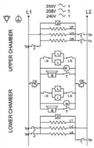


LEGEND
N. L1, L2, L3 = FROM TERMINAL BLOCK
TH = THERMOSTAT 2 POLE (3 POLE)
P = THERMOSTAT INDICATOR LIGHT
CB = CIRCUIT BREAKER
M = SYNCHRONOUS TIMER (OR TIMER MOTOR)
T = INTERVAL TIMER CONTACTS (IF PROVIDED)
B = BUZZER (IF PROVIDED)
LS = LIGHT SWITCH DPST ON-OFF (IF PROVIDED)
L = INTERIOR LIGHTS (IF PROVIDED)
HEATER COILS
UT = UPPER CHAMBER, TOP ELEMENT
UC = UPPER CHAMBER, CENTER ELEMENT
(P44 & P46 ONLY)
UB = UPPER CHAMBER, BOTTOM ELEMENT
LT = LOWER CHAMBER, TOP ELEMENT
LC = LOWER CHAMBER, CENTER ELEMENT (P44 ONLY)
LB = LOWER CHAMBER, BOTTOM ELEMENT
P-Series 2 Chambers – Electrical Wiring & Tables
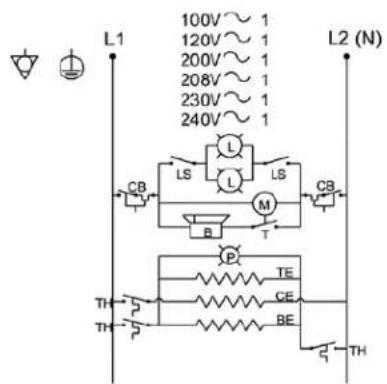
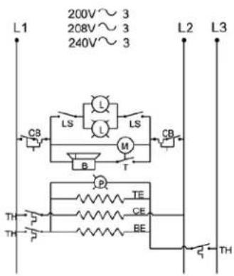
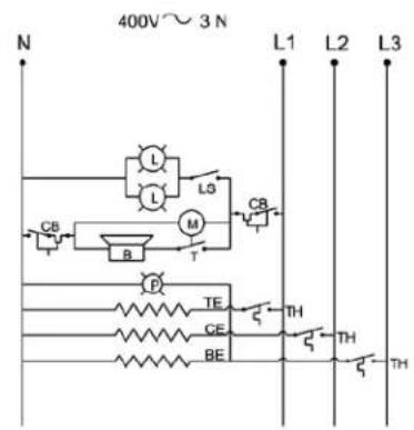
LEGEND HEATER COILS
N, L1, L2, L3 = FROM TERMINAL BLOCK TE = TOP ELEMENT
TH = THERMOSTAT 2 POLE (3 POLE) CE = CENTER ELEMENT (IF PROVIDED)
P = THERMOSTAT INDICATOR LIGHT BE = BOTTOM ELEMENT
CB = CIRCUIT BREAKER
M = SYNCHRONOUS TIMER (OR TIMER MOTOR)
T = INTERVAL TIMER CONTACTS (IF PROVIDED)
B = BUZZER (IF PROVIDED)
LS = LIGHT SWITCH DPST ON-OFF (IF PROVIDED)
L = INTERIOR LIGHTS (IF PROVIDED)
P-Series 1 Chamber – Electrical Wiring Schematics
WIRING DIAGRAMS
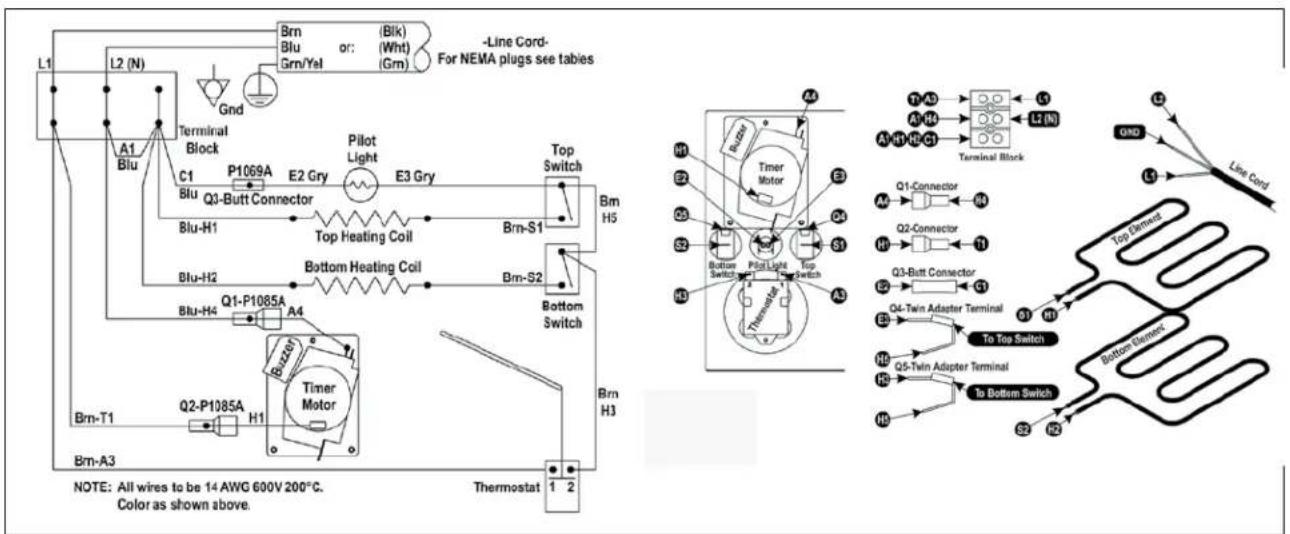
PX-14 & PX-16 – Electrical Wiring Diagram Tables
PX-14
| Volts A/C/Phase | AMP NEMA | Plug Configuration & Number Heating Coils | Watts/Volts | Timer Motor Volts/Hz | ||||
| USA CANADA UK EUROPE JAPAN | ||||||||
| 100/1 15 |  | 750/100 120/60 | ||||||
| 120/1 12.5 |  5-15P 5-20P 5-15P 5-20P |  — — | 750/100 120/60 | |||||
| 200/1 7.5 |  | 750/200 250/60 | ||||||
| 208-240/1 8.1 |  6-15P 6-15P 6-15P 6-15P |  — — | 750/220 250/60 | |||||
| 220-240/1 8.1 | [DSAA]BS 1363A CEE7-VII |  | 750/220 250/60 | |||||
PX-16
| Volts A/C/Phase | AMP NEMA | Plug Configuration & Number Heating Coils | Watts/Volts | Timer Motor Volts/Hz | ||||
| USA CANADA UK EUROPE JAPAN | ||||||||
| 100/1 18 9 | 00/100 125/60 |  | ||||||
| 120/1 15 | [W80C]5-15P 5-20P |  | 900/100 125/60 | |||||
| 200/1 9 | 6-15P | 900/200 250/60 | ||||||
| 208-240/1 9.7 | [28YD]6-15P 6-15P |  | 900/220 250/60 | |||||
| 220-240/1 9.7 |  BS 1363A CE E7-VII BS 1363A CE E7-VII | [CZXBH] | 900/220 250/60 | |||||
EXPLODED VIEWS & PARTS LISTS
PX-14 Beginning: Serial #4633, 12/09/99 (120V) or Serial #6547, 11/22/99 (208/240V)
PX-16 Beginning: Serial #959, 11/11/99 (120V) or Serial #1783, 12/01/99 (208/240V)
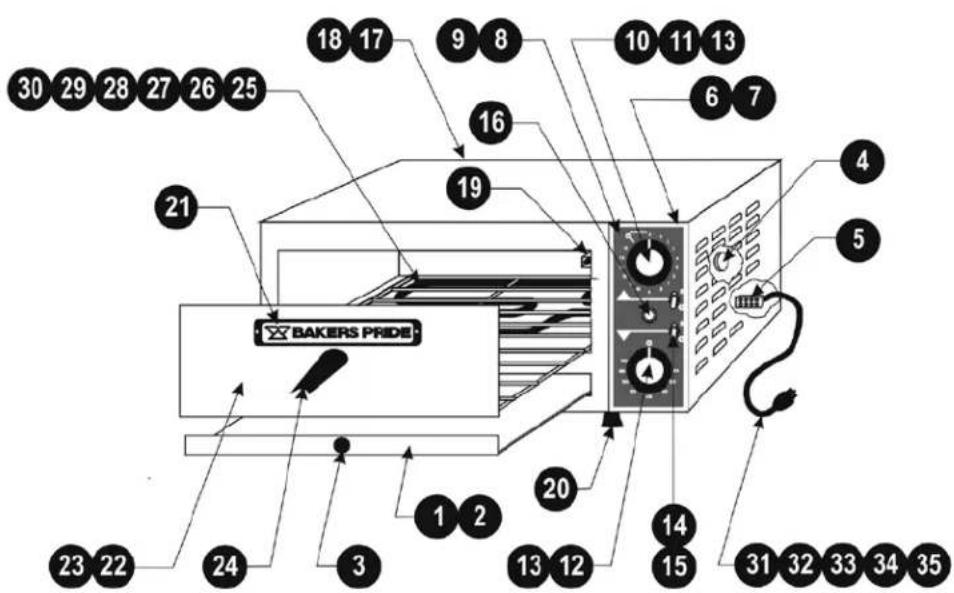
PX-14/16 New Style
| Item P/N Description |
| 1 D5023X Crumb Pan Assy w/Knob (PX-14) |
| 2 D5123X Crumb Pan Assy w/Knob (PX-16) |
| 3 S1153X Knob (Crumb Pan) |
| 4 M1335X Audio Alarm |
| 5 P1003X Terminal Block, 3 Pole |
| 6 D5027U Control Panel Assy, Front (PX-14) |
| 7 D5127X Control Panel Assy, Front (PX-16) |
| 8 U1308A Control Panel Overlay, 60hz |
| 9 U1309A Control Panel Overlay, 50hz |
| 10 M1383A Timer, Electro-Mechanical, 15 Minutes, 120V |
| 11 M1384A Timer, Electro-Mechanical, 15 Minutes, 220V |
| 12 M1119X Thermostat, EGO, 300-650 deg (No Knob) |
| 13 S1311X Knob (Thermostat & Timer) |
| 14 M1037X Switch, Toggle, On/Off |
| 15 S1038X Rubber Boot, On/Off Switch (Export) |
| 16 P1127X Pilot Light, Amber |
| 17 D5038U Rear Panel Assy, (PX-14) |
| 18 D5138U Rear Panel Assy, (PX-16) |
| Item P/N Description | |
| 19 D5043U Capillary | Retainer Assy |
| 20 S1392A Leg, each | |
| 21 U1044X Bakers Pride Nameplate, 8" | |
| 22 D5037U Peel Tray | Assy w/Wire Rack & Hdl (PX-14) |
| 23 D5141U Peel Tray | Assy w/Wire Rack & Hdl (PX-16) |
| 24 S1031X Handle, w/Nut & Bolt | |
| 25 L1065X Element, PX-14, 120V/750W (2) | |
| 26 L1148X Element, PX-16, 120V/900W (2) | |
| 27 L1066X Element, PX-14, 220V/750W (2) | |
| 28 L1149X Element, PX-16, 220V/900W (2) | |
| 29 L1067X Element, PX-14, 100V/750W (2) Japan | |
| 30 L1156X Element, PX-16, 200V/900W (2) Japan | |
| 31 P5004X Line Cord, 125V/15A | |
| 32 P5383A Line Cord, 125V/20A (Canada) | |
| 33 P5005X Line Cord, 250V/15A | |
| 34 P5006X Line Cord, CEE7-VII (Europe) | |
| 35 P5343X Line Cord w/Fuse, 13A/240V (U.K.) | |
Note: When ordering, always specify Part#, Model#, Serial# and Voltage/Phase.
EXPLODED VIEWS & PARTS LISTS
PX-14 Before: Serial #4633, 12/09/99 (120V) or Serial #6547, 11/22/99 (208/240V)
PX-16 Before: Serial #959, 11/11/99 (120V) or Serial #1783, 12/01/99 (208/240V)

PX-14/16 Old Style
| Item P/N Description |
| 1 D5023X Crumb Pan Assy w/Knob (PX-14) |
| 2 D5123X Crumb Pan Assy w/Knob (PX-16) |
| 3 S1153X Knob (Crumb Pan) |
| 4 P1003X Terminal Block, 3 Pole |
| 5 M1017X Timer, Mech, 15 Minutes (w/Knob/Plate) |
| 6 S1052X Knob, Timer |
| 7 S1025X Plate, Timer |
| 8 M1120X Thermostat, EGO, 650F deg (w/Knob) |
| 9 M1119X Thermostat, EGO, 370C deg (w/Knob) |
| 10 S1155X Knob, Thermostat (650F) |
| 11 S1154X Knob, Thermostat (370C) |
| 12 M1037X Switch Toggle, On/Off |
| 13 S1038X Rubber Boot, On/Off Switch (Export) |
| 14 P1127X Pilot Light, Amber |
| 15 D5038U Rear Panel Assy, (PX-14) |
| 16 D5138U Rear Panel Assy, (PX-16) |
| 17 D5043U Capillary Retainer Assy |
| 18 S1392A Leg, each |
| Item P/N Description |
| 19 U 1044X Bakers Plide Nameplate, 8" |
| 20 D 5037U Peel Tray Assy w/Wire Rack (PX-14) |
| 21 D 5141U Peel Tray Assy w/Wire Rack (PX-16) |
| 22 S 1031X Handle, w/Nut & Bolt |
| 23 L 1065X Element, PX-14, 120V/750W (2) |
| 24 L 1148X Element, PX-16, 120V/900W (2) |
| 25 L 1066X Element, PX-14, 220V/750W (2) |
| 26 L 1149X Element, PX-16, 220V/900W (2) |
| 27 L 1067X Element, PX-14, 100V/750W (2) Japan |
| 28 L 1156X Element, PX-16, 200V/900W (2) Japan |
| 29 P 5004X Line Cord, 125V/15A |
| 30 P 5383A Line Cord, 125V/20A (Canada) |
| 31 P 5005X Line Cord, 250V/15A |
| 32 P 5006X Line Cord, CEE7-VII (Europe) |
| 33 P 5343X Line Cord w/Fuse, 13A/240V (U.K.) |
Note: When ordering, always specify Part#, Model#, Serial# and Voltage/Phase.
EXPLODED VIEWS & PARTS LISTS

P18-S, BK18 Exterior / Door / Controls (Electro-Mechanical Timers)
| Item P/N Description |
| 1 M1098X Thermostat w/Knob, EGO (Standard) P-18 |
| 2 M1192X Thermostat w/Knob, EGO (High Heat) P-18 |
| 3 M1110X Thermostat w/Knob, KA-72, 550deg (BK-18) |
| 4 S1311X Knob (Thermostat & Timer) |
| 5 M1381A Timer, Elec-Mech, 60 Min, 120V (BK-18) |
| 6 M1382A Timer, Elec-Mech, 60 Min, 220V (BK-18) |
| 7 M1383A Timer, Elec-Mech, 15 Min, 120V (P-18) |
| 8 M1384A Timer, Elec-Mech, 15 Min, 220V (P-18) |
| 9 D3157K Control Panel |
| 10 M1330A Circuit Breaker, 3 Amp |
| 11 M1335X Audio Alarm (Discontinued) |
| 12 P1127X Pilot Light, Amber |
| 13 P1089A Terminal Block, 3 Pole |
| 14 P6004X Line Cord 125V/15A (US) P & BK |
| 15 P6005X Line Cord 250V/15A (US & Japan) P & BK |
| 16 P6383X Line Cord 125V/20A (Canada) |
| 17 P6009X Line Cord 250V/20A (Canada) |
| 18 P6006X Line Cord, 230V/16A “C” Type (CE) |
| 19 P6343X Line Cord, 230V/13A (UK) |
| Item P/N Description | |
| 20 U | 1302X Control Panel Overlay, EGO (P-18) |
| 21 U | 1307A Control Panel Overlay, EGO Hi-Heat (P-18) |
| 22 U | 1314A Control Panel Overlay (BK-18) |
| 23 U | 1297A 18 Minute Timer Overlay (50 cycles) |
| 24 U | 1296A 72 Minute Timer Overlay (50 cycles) |
| 25 S | 3019X Bushing, Door |
| 26 D | 3106X Door Assy w/Handle |
| 27 S | 3001X Door Rod |
| 28 Q | 3021X Door Rod Spacer Kit (1 Kit per Door) |
| 29 D | 3105K Outer Back |
| 30 S | 1316U Door Handle Assy, 10" |
| 31 Q | 2041A Screw, 1/4-20 x 1/2 Rd Hd (Door Handle) |
| 32 U | 1044X Bakers Pride Nameplate, 8" |
| 33 S | 1014X 4" Adjustable Leg (Set/4) |
| 34 S | 1014Y 4" Adjustable Leg (each) |
| 35 T | 3150A Intermediate Wire Rack (Option, BK18) |
| 36 D | 3162U Wire Rack Support Assy, Left (Option) |
| 37 D | 3163U Wire Rack Support Assy, Right (Option) |
| N/S D | 2069X Stacking Kit |


Deck Arrangement by Model
Note: When ordering, always specify Part#, Model#, Serial# and Voltage/Phase.
EXPLODED VIEWS & PARTS LISTS
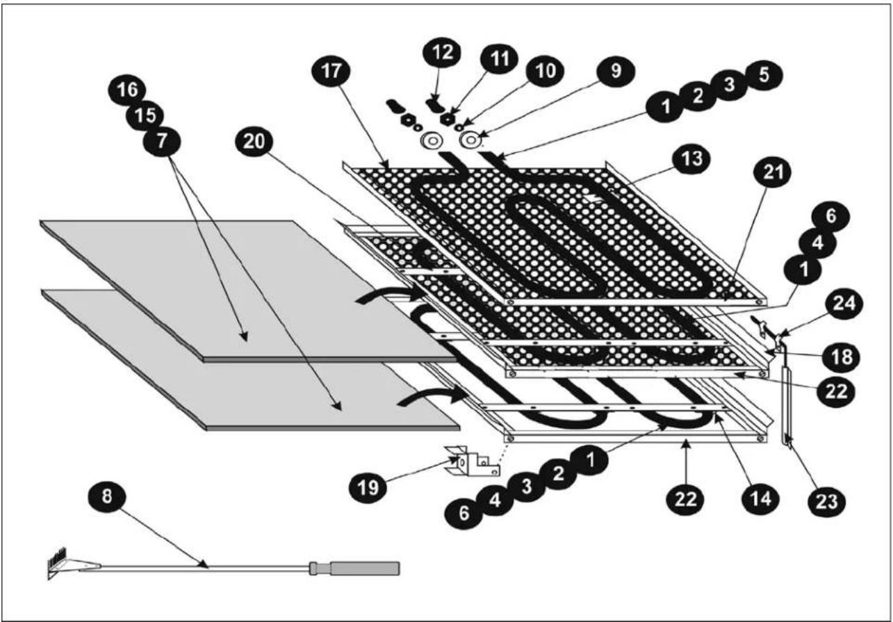
P18, BK18 Interior Components & Accessories
| Item P/N Description | ||
| 1 L1024X Element 115V/600W (US/Can) P-18, T,C & B | ||
| 2 L1171X Element 115V/850W (US/Can) BK-18, T & B | ||
| 3 L1025X Element 208-240V/850W (US/Can/CE)P Top, BK T&B | ||
| 4 L1026X Element 208-240V/1KW (US/Can/CE) P-18 C & B | ||
| 5 L1112X Element 200V/850W (Japan) P-18 Top | ||
| 6 L1113X Element 200V/1000W (Japan) P-18 C & B | ||
| 7 T5118X Steel Bake Deck (BK18 Only) | ||
| 8 T5107Y Deck Scraper Brush | ||
| 9 P1019X Porcelain Spacer | ||
| 10 Q3016A Washer Star, #6 | ||
| 11 Q1002A Nut, 6-32 | ||
| 12 S1061X 6-32 Terminal Cap |
| Item P/N Description | ||
| 13 K1355X Baffle & Top Elem. Clips (5) BK | ||
| 14 P1042A Element Clip, 5/16", Center & Bottom | ||
| 15 T1120Y Ceramic Deck, 17 1/2 x 17 3/4 x 1/2 (each) | ||
| 16 T1120X Ceramic Deck, 17 1/2 x 17 3/4 x 1/2 (set/2) | ||
| 17 D3140Z Fresh Dough Baffle | ||
| 18 D3152T Hearth Frame Assy | ||
| 19 D4039K Deck Support | ||
| 20 D3151K Element Support | ||
| 21 D3131K Baffle Trim | ||
| 22 D3142K Deck Trim | ||
| 23 D1134K Capillary Cover | ||
| 24 Q4021X Clip 3/16", Temp Sensor (2) |
Note: When ordering, always specify Part#, Model#, Serial# and Voltage/Phase.
EXPLODED VIEWS & PARTS LISTS

P-22BL, P-22S, P-24S Exterior / Door / Controls (Electro-Mechanical Timers)
![graph LR A["11"] --> B["09:18"] B --> C["14"] C --> D["1"] C --> E["2"] C --> F["3"] C --> G["4"] C --> H["5"] C --> I["20"] C --> J["21"] C --> K["22"] B --> L["9"] B --> M["8"] B --> N["12"] B --> O["14"]](/content/2026/07/1447475/images/cae76976ba3990991be8984c0c5b272ed3ba73f5967a644204870105484b9bc5.jpg)
Control Panel with Digital Timer (Optional)

Deck Arrangement by Model
| Item P/N Description |
| 1 M1098X Thermostat w/Knob, 650F (EGO) |
| 2 M1192X Thermostat w/Knob, CE “430C” (High Heat) |
| 3 M1110X Thermostat w/Knob, 550F, KA-72 (P-24S) |
| 4 M1342X Thermostat Kit w/Knob, 250F (Special) |
| 5 S1311X Knob (T-s at “F”, 15 Min Timer: Rot-Elec) |
| 6 M1384A Timer, Electro-Mech, 15 Min, (P-22S & P-22BL) |
| 7 M1382A Timer, Electro-Mech, 60 Min (P-24S) |
| 8 M1275X Timer, Electronic (Digital Readout) 60 cycle |
| 9 M1274X Timer, Electronic (Digital Readout) 50 cycle |
| 10 D1157K Control Panel (Rot/Elect Timer) |
| 11 D1156K Control Panel (Electronic Timer) |
| 12 M1330A Circuit Breaker, 3A |
| 13 M1335X Audio Alarm (Discontinued) |
| 14 P1127X Pilot Light, Amber |
| 15 P1003X Terminal Block, 3 Pole, 1 Phase |
| 16 P1004X Terminal Block, 4 Pole, 3 Phase |
| 17 P6009X Line Cord, 250V/20A (USA & Canada) |
| 18 P6385A Line Cord, 250V/30A (Can. 208V only) P22S/BL |
| 19 P6005X Line Cord, 250V/15A (P-24S) |
| 20 U1302X Control Panel Overlay, 22S & 22BL |


| Item P/N Description |
| 21 U1307A Control Panel Overlay, Hi Heat, 22S & 22BL |
| 22 U1314A Control Panel Overlay, P-24S |
| 23 U1297A 18 Minute Timer Overlay (50 cycle) |
| 24 U1296A 72 Minute Timer Overlay (50 cycle) |
| 25 S3019X Door Bushing |
| 26 D1106X Door Assy (No Window) |
| 27 S1020X Window Assy (Door) |
| 28 D1143U Door Assy (w/Window) |
| 29 S3001X Door Rod |
| 30 Q3021X Door Rod Spacer Kit (1 Kit per Door) |
| 31 D1105K Outer Back |
| 32 S1316U Door Handle |
| 33 Q2041A Screws, 1/4-20 x 1/2 RH (Door Handle) |
| 34 U1044X Bakers Pride Nameplate, 8" |
| 35 S1014X 4" Adjustable Leg (Set/4) |
| 36 S1014Y 4" Adjustable Leg (each) |
| 37 T3139X Intermediate Wire Rack (Option, P-24) |
| 38 D1162U Wire Rack Support Assy, Left (Option) |
| 39 D1163U Wire Rack Support Assy, Right (Option) |
| 40 D2069X Stacking Kit |
Note: When ordering, always specify Part#, Model#, Serial# and Voltage/Phase.
EXPLODED VIEWS & PARTS LISTS

P-22BL, P-22S, P-24S Interior Components & Accessories
| Item P/N Description |
| 1 L1072X Element, 208V/1075W, Top & Bottom |
| 2 L1071X Element, 208V/1450W, Center |
| 3 L1035X Element, 230V/1075W, Top & Bottom |
| 4 L1034X Element, 230V/1450W, Center |
| 5 L1116X Element, 200V/1075W, Top & Bottom (Japan) |
| 6 L1117X Element, 200V/1450W, Center (Japan) |
| 7 P1019A Porcelain Spacer |
| 8 Q3016A Washer, Star, #6 |
| 9 Q1002A Nut, 6-32 |
| 10 S1061X Terminal Cap, 6-32 |
| 11 K1355X Element Clip |
| 12 D1158U Ceramic Top Frame Assy (B/L Only) |
| Item P/N Description | ||
| 13 T | 120Y Deck, ea. | 17 3/4 x 17 1/2 x 1/2 (P-22BL only) |
| 14 T | 121Y Deck, 20 | 13/16 x 20 13/16 x 1/2 (each) |
| 15 T | 121X Deck, 20 | 13/16 x 20 13/16 x 1/2 (set/2) |
| 16 D | 4040X Fresh Dough Baffle | |
| 17 D | 1152T Hearth Frame Assy (No Element) | |
| 18 D | 4039K Deck Support | |
| 19 D | 4031X Baffle Trim | |
| 20 D | 1142K Hearth Trim | |
| 21 D | 1134K Capillary Cover | |
| 22 Q | 4021X Clip, 3/16" | |
| 23 T | 1222K Steel Bake Deck (Optional) | |
| 24 T | 5107Y Deck Scraper Brush | |
Note: When ordering, always specify Part#, Model#, Serial# and Voltage/Phase.
EXPLODED VIEWS & PARTS LISTS

P-44S, P-44BL, P-46S, P-48S Exterior/Door/Controls (No Lights, Electro-Mechanical Timers)

Control Panel with Lights & Digital Timers (Optional)
| Item P/N Description |
| 1 M1098X Thermostat w/Knob, 650F EGO, 44(2) 46(1) |
| 2 M1192X Thermostat w/Knob, CE “430C” High Heat 44 |
| 3 M1342X Thermostat Kit w/Knob, 250F (Special) |
| 4 M1110X Thermostat w/Knob, 550F KA72, 46 (1), 48 (2) |
| 5 S1311X Knob (T-stat “F”, 15 Min Timer: Rot-Elec) |
| 6 M1384A Timer, Elec-Mech, 15 Min, 44(2) 46(1) |
| 7 M1382A Timer, Elec-Mech, 60 Min, 46(1) 48(2) |
| 8 M1275X Timer, Electronic (Digital Readout) 60 cycle |
| 9 M1274X Timer, Electronic (Digital Readout) 50 cycle |
| 10 M1259X Toggle Switch (Lights, On/Off) |
| 11 D2157K Control Panel (Rot/Elect Timer-No Lights) |
| 12 D2101K Control Panel (Rot/Elect Timer-w/Lights) |
| 13 D2156K Control Panel (Electronic Timer-No Lights) |
| 14 D2102K Control Panel (Electronic Timer-w/Lights) |
| 15 M1330A Circuit Breaker, 3A |
| 16 P1127X Pilot Light, Amber |
| 17 P1003X Terminal Block, 3 Pole, 1 Phase |
| 18 P1004X Terminal Block, 4 Pole, 3 Phase |
| 19 P6399A Line Cord, 125/250V, 50A |
| 20 P6385A Line Cord, 250V, 30A (P-46 & P-48) |
| 21 U1304A Control Panel Overlay (44 & 44BL) |
| 22 U1310A Control Panel Overlay, Hi Heat (44 & 44BL) |
| 23 U1316A Control Panel Overlay (P-46) |
| 24 U1318A Control Panel Overlay (P-48) |
| Item P/N Description | |
| 25 U | 1297A 18 Minute Timer Overlay (50 cycles) |
| 26 U | 1296A 72 Minute Timer Overlay (50 cycles) |
| 27 S | 3019X Door Bushing |
| 28 D | 1106U Door Assy (No Window) |
| 29 S | 1020X Window Assy (Door) |
| 30 D | 1143U Door Assy (w/Window) |
| 31 P | 1145X Light Fixture (w/240V,15W Bulb) |
| P1129X Light Fixture (Old Style, 3" Diameter) | |
| 32 P | 1147X Light Bulb, 240V/15W |
| P1020X Light Bulb, (Old Style, 115V) | |
| P1122X Light Bulb, (Old Style, 250V) | |
| 33 S | 3001X Door Rod |
| 34 Q | 3021X Door Rod Spacer Kit (1 Kit per Door) |
| 35 D | 2105K Outer Back |
| 36 S | 1316U Door Handle |
| 37 Q | 2041A Screws, 1/4-20 x 1/2 RH (Door Handle) |
| 38 U | 1044X Bakers Pride Nameplate, 8" |
| 39 S | 1014X 4" Adjustable Leg (Set/4) |
| 40 S | 1014Y 4" Adjustable Leg (each) |
| 41 T | 139A Intermediate Wire Rack (Option 46 & 48) |
| 42 D | 1162U Wire Rack Support Assy, Left (Option) |
| 43 D | 1163U Wire Rack Support Assy, Right (Option) |
| 44 M | 1335A Audio Alarm (Discontinued) |
| 45 D | 2069X Stacking Kit |
Note: When ordering, always specify Part#, Model#, Serial# and Voltage/Phase.
EXPLODED VIEWS & PARTS LISTS
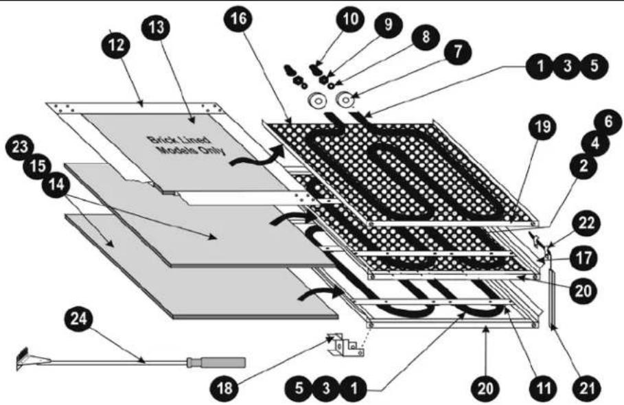
P-44S, P-44BL, P-46S, P-48S Interior Components & Accessories


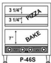

Deck Arrangement by Model
| Item P/N Description | |
| 1 L1072X Element, 208V/1075W, Top & Bottom | |
| 2 L1071X Element, 208V/1450W, Center | |
| 3 L1035X Element, 230V/1075W, Top & Bottom | |
| 4 L1034X Element, 230V/1450W, Center | |
| 5 L1117X Element, 200V/1075W, Top & Bottom (Japan) | |
| 6 L1116X Element, 200V/1450W, Center (Japan) | |
| 7 P1019A Porcelain Spacer | |
| 8 Q3016A Washer, Star, #6 | |
| 9 Q1002A Nut, 6-32 | |
| 10 S1061X Terminal Cap, 6-32 | |
| 11 K1355X Element Clip | |
| 12 D1158U Ceramic Top Frame Assy (P-44BL Only) | |
| Item P/N Description | ||
| 13 T | 120Y Deck, ea. | 17 3/4 x 17 1/2 x 1/2 (P-44BL only) |
| 14 T | 121Y Deck, 20 | 13/16 x 20 13/16 x 1/2 (each) |
| 15 T | 121X Deck, 20 | 13/16 x 20 13/16 x 1/2 (set/2) |
| 16 D | 4040X Fresh Dough Baffle | |
| 17 D | 1152T Hearth Frame Assy (No Element) | |
| 18 D | 4039K Deck Support | |
| 19 D | 4031X Baffle Trim | |
| 20 D | 1142K Hearth Trim | |
| 21 D | 1134K Capillary Cover | |
| 22 Q | 4021X Clip, 3/16" | |
| 23 T | 222K Steel Bake Deck (Optional) | |
| 24 T | 107Y Deck Scraper Brush | |
Note: When ordering, always specify Part#, Model#, Serial# and Voltage/Phase.
EXPLODED VIEWS & PARTS LISTS
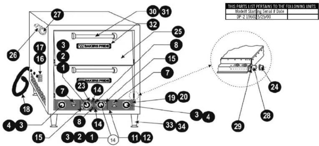
DP-2 Exterior / Door / Controls (Electro-Mechanical Timers)

Control Panel with Digital Timers & Infinite Switches (Optional)
| Item P/N Description |
| 1 M 098X Thermostat w/Knob, EGO |
| 2 M 192X T-stat w/knob, CE “430C” (High Heat) |
| 3 S 311X Knob (Thermostat & Timer) |
| 4 M 384A Timer, Elec-Mech, 15 Min (220V) |
| 5 M 275X Timer, Electronic, 60Hz (Domestic) |
| 6 M 274X Timer, Electronic, 50Hz (CE) |
| 7 M 335X Audio Alarm (Discontinued) |
| 8 M 259X Toggle Switch (Lights, On/Off) |
| 9 M 367A Infinite Switch, 208V |
| 10 S 205X Knob, Infinite Switch |
| 11 D 2101U Control Panel (Rot-Elec Timer) |
| 12 D 4046U Control Panel (Rot-Elec Timer/Infinite Sw.) |
| 13 D 4045U Control Panel (Electronic Timer/Infinite Sw.) |
| 14 M 1330A Circuit Breaker, 3A |
| 15 P 1127X Pilot Light, Amber |
| 16 P 1003X Terminal Block, 3 Pole (Domestic) |
| 17 P 1004X Terminal Block, 4 Pole (CE) |
| Item P/N Description |
| 18 P5385A Line Cord, 250V/30A |
| 19 U1304A Control Panel Overlay |
| 20 U1310A Control Panel Overlay (High-Heat) |
| 21 U1289A Overlay, Top Infinite Controls |
| 22 U1288A Overlay, Bottom Infinite Controls |
| 23 U1297A 18 Minute Timer Overlay (50 cycles) |
| 24 S3019X Door Bushing |
| 25 D4006X Door Assembly |
| 26 P1145X Light Fixture (w/240V, 15W Bulb) |
| 27 P1147X Light Bulb, 240V/15W |
| 28 S3001X Door Rod |
| 29 Q3021X Door Rod Spacer Kit (1 Kit per Door) |
| 30 S1316U Door Handle |
| 31 Q2041A Screws, 1/4-20 x 1/2 RH (Door Handle) |
| 32 U1044X Bakers Pride Nameplate, 8" |
| 33 S1014Y 4" Adjustable Leg (each) |
| 34 S1014X 4" Adjustable Leg (Set/4) |
| N/S D2069X Stacking Kit |
Note: When ordering, always specify Part#, Model#, Serial# and Voltage/Phase.
EXPLODED VIEWS & PARTS LISTS

DP-2 Interior Components
| Item P/N Description |
| 1 L1072X Element, 208V/1075W, Top |
| 2 L1071X Element, 208V/1450W, Bottom |
| 3 L1034X Element, 230V/1075W, Top |
| 4 L1035X Element, 230V/1450W, Bottom |
| 5 L1117X Element, 200V/1075W, Top (Japan) |
| 6 L1116X Element, 200V/1450W, Bottom (Japan) |
| 7 P1019X Porcelain Spacer |
| 8 Q3016A Washer, Star, #6 |
| 9 Q1002A Nut, 6-32 |
| 10 S1061X Terminal Cap, 6-32 |
| Item P/N Description | |
| 11 K1355X Element Clip | |
| 12 T1121Y Hearth Deck 20 13/16 x 20 13/16 x 1/2 (each) | |
| 13 T1121X Hearth Deck 20 13/16 x 20 13/16 x 1/2 (Set/2) | |
| 14 D4040X Fresh Dough Baffle | |
| 15 D1152T Hearth Frame Assy | |
| 16 D4039K Deck Support | |
| 17 D4031K Baffle Trim | |
| 18 D4034K Capillary Cover | |
| 19 Q4021X Clip, 3/16†(Capillary) | |
| 20 D1142K Deck Trim | |
Note: When ordering, always specify Part#, Model#, Serial# and Voltage/Phase.
BAKERS PRIDE LIMITED WARRANTY
WHAT IS COVERED
This warranty covers defects in material and workmanship under normal use, and applies only to the original purchaser providing that:
- The equipment has not been accidentally or intentionally damaged, altered or misused;
- The equipment is properly installed, adjusted, operated and maintained in accordance with National and local codes and in accordance with the installation instruction provided with the product;
- The serial number rating plate affixed to the equipment has not been defaced or removed.
WHO IS COVERED
This warranty is extended to the original purchaser and applies only to equipment purchased for use in the U.S.A.
COVERAGE PERIOD
Cyclone Convection Ovens: BCO Models: One (1) Year limited parts and labor; (1) Year limited door warranty.
GDCO Models: Two (2) Year limited parts and labor; (2) Year limited door warranty.
CO11 Models: Two (2) Year limited parts and labor; (5) Year limited door warranty.
All Other Products: One (1) Year limited parts and labor. Warranty period begins the date of dealer invoice to customer or ninety (90) days after shipment date from Bakers Pride - whichever comes first.
WARRANTY
This warranty covers on-site labor, parts and reasonable travel time and travel expenses of the authorized service
COVERAGE
Representative up to (100) miles, round trip, and (2) hours travel time. The purchaser, however, shall be responsible for all expenses related to travel, including time, mileage and shipping expenses on smaller counter models that may be carried into a Factory Authorized Service Center, including the following models: PX-14, PX-16, P18, P22S, P24S, PD-4, PDC, WS Series and BK-18.
EXCEPTIONS All removable
parts in Bakers Pride ® cooking equipment, including but not limited to: Burners, Grates, Radiants, Stones and Valves, are covered for a period of SIX MONTHS. All Ceramic Baking Decks are covered for a period of THREE MONTHS. The installation of these replacement decks is the responsibility of the purchaser. The extended Cyclone door warranty years 3 through 5 is a parts only warranty and does not include labor, travel, mileage or any other charges.
EXCLUSIONS
- Negligence or acts of God,
- Failures caused by erratic voltages or gas supplies,
• Thermostat calibrations after (30) days from equipment installation date, - Unauthorized repair by anyone other than a Bakers Pride Factory Authorized Service Center,
• Air and Gas adjustments, - Damage in shipment,
• Light bulbs, -
Alteration, misuse or improper installation,
• Glass doors and door adjustments, -
Thermostats and safety valves with broken capillary tubes,
- Fuses,
• Char-broiler work decks and cutting boards, - Tightening of conveyor chains,
- Adjustments to burner flames and cleaning of pilot burners,
- Tightening of screws or fasteners,
- Accessories — spatulas, forks, steak turners, grate lifters, oven brushes, scrapers, peels. etc.,
• Freight — other than normal UPS charges,
• Ordinary wear and tear.
INSTALLATION
Leveling and installation of decks as well as proper installation and check out of all new equipment — per appropriate installation and use materials — is the responsibility of the dealer or installer, not the manufacturer.
REPLACEMENT PARTS
Bakers Pride genuine Factory OEM parts receive a (90) day materials warranty effective from the date of installation by a Bakers Pride Factory Authorized Service Center.
This Warranty is in lieu of all other warranties, expressed or implied, and all other obligations or liabilities on the manufacturer's part. Bakers Pride shall in no event be liable for any special, indirect or consequential damages, or in any event for damages in excess of the purchase price of the unit. The repair or replacement of proven defective parts shall constitute a fulfillment of all obligations under the terms of this warranty.
Form #U4177A 1/07
IMPORTANT FOR FUTURE REFERENCE
Please complete this information and retain this manual for the life of the equipment. For Warranty Service and/or Parts, this information is required.
Model Number Serial Number Date Purchased
NOTES

Standex
Food Service Equipment Group
The Standex Food Service Equipment Group (FSEG) is a manufacturer of innovative commercial food service equipment offering a wealth of refrigeration and cooking expertise. Products include walk-in coolers and freezers; hot and cold display cabinets, cases, and storage systems; commercial ovens, rotisseries, and cooking equipment; and rotary vane pumps.
Ask your sales representative about how the power of all Standex brands can work for you.
www.standex.com/segments/food-service

Be sure to keep up with new product announcements and events on social media!


You Tube
- COUNTERTOP ELETRIC OVENS
- WARNING
- CAUTION
- NOTICE
- SAFETY PRECAUTIONS
- DANGER
- INSTALLATION INSTRUCTIONS
- MINIMUM CLEARANCE FOR INSTALLATION
- LOCATION
- ELECTRICAL CONNECTIONS
- REQUIREMENTS FOR INSTALLATION
- INITIAL START UP
- OPERATING INSTRUCTIONS
- GENERAL BAKING
- GENERAL BAKING TIPS
- SPECIAL FEATURES
- CLEANING
- SERVICE AND TROUBLESHOOTING
- WIRING DIAGRAMS
- LEGEND
- HEATER COILS
- EXPLODED VIEWS & PARTS LISTS
- BAKERS PRIDE LIMITED WARRANTY
- WHAT IS COVERED
- WHO IS COVERED
- COVERAGE PERIOD
- WARRANTY
- COVERAGE
- EXCEPTIONS ALL REMOVABLE
- EXCLUSIONS
- INSTALLATION
- REPLACEMENT PARTS
- IMPORTANT FOR FUTURE REFERENCE
- NOTES
- STANDEX
Brand : Bakers Pride
Model : PX-14
Category : Pizza oven