
HDC-305-84 - Appareil de manutention hydraulique Vestil - Free user manual and instructions
Find the device manual for free HDC-305-84 Vestil in PDF.


| Product Type | Drum Dolly |
| Brand | Vestil |
| Model | HDC-305-84 |
| Weight Capacity | 1000 lb (454 kg) |
| Handle Length | 84 in (213 cm) |
| Dimensions (L x W x H) | 30 x 24 x 84 in (76 x 61 x 213 cm) |
| Net Weight | 25 lb (11.3 kg) |
| Frame Material | Steel |
| Finish | Yellow Powder Coat |
| Wheel Material | Polyurethane |
| Number of Wheels | 4 |
| Compatible Drum Size | 55 gal (standard steel or plastic) |
| Safety Features | Non-slip handle grip; welded steel construction |
| Maintenance | Lubricate wheel axles every 6 months; clean with mild detergent |
| Replacement Parts Availability | Replacement wheels (model WHEEL-305) and handle grips available |
| Warranty | 1 year limited |
| Country of Origin | USA |
| Usage Instructions | See user manual for detailed assembly and operation |
Frequently Asked Questions - HDC-305-84 Vestil
User questions about HDC-305-84 Vestil
0 question about this device. Answer the ones you know or ask your own.
Ask a new question about this device
Download the instructions for your Appareil de manutention hydraulique in PDF format for free! Find your manual HDC-305-84 - Vestil and take your electronic device back in hand. On this page are published all the documents necessary for the use of your device. HDC-305-84 by Vestil.
USER MANUAL HDC-305-84 Vestil
VESTIL MANUFACTURING CORPORATION
2999 North Wayne Street, P.O. Box 507
Angola, Indiana 46703 USA
Phone (260) 665-7586 • Fax (260) 665-1339
sales@vestil.com • www.vestil.com
Revised 05-04 09-126-108
A company dedicated to solving ergonomic and material handling problems since 1955.
OWNER'S
MANUAL
HYDRAULIC DRUM CARRIER/ROTATOR
MODEL HDC-305-60/72/84/96
Contents
Warnings and Safety Instructions .... 1
Receiving Instructions 1
Loading Instructions 2
Operating Instructions 2
Instructions for Battery-Powered Units....3
Periodic Maintenance Instruction 4
Exploded Parts Drawing/Lists 5-8
The Power Unit's Operation....9
Electrical Schematic 10
Hydraulic Schematic/Parts List 11-13
Troubleshooting 14
Warning Label Identification 15
Limited Warranty/Service Record 16
WARNINGS & SAFETY INSTRUCTIONS
Read owner's manual completely before operating unit!
- Remove drum & disconnect power before working on unit.
- The carrier is designed to be used for dumping only fluid or semi-fluid loads from open-topped steel 55 gallon drums. Dumping capacity is reduced to 500 lbs. for drums whose fill level is 50% or less.
- Do not attempt to lift or rotate damaged drums.
- Always have the floor lock engaged solidly with the floor surface when a drum is being rotated.
- Verify that the drum is securely held by the carrier before lifting or rotating it.
- Drums must be vertical while being transported.
- Always watch the carriage and the barrel carefully when the carrier is in operation.
- Stand behind and to the side of the carriage when a drum is being rotated.
- Be alert to the possibility of splashing when dumping wet and / or dense loads.
- Do not allow personnel underneath any part of the drum carrier while it is raised.
- For battery-powered units, review the additional warning included elsewhere in this manual.
- Ensure that all safety and warning labels stay in place and are legible. See the labels page in this manual.
- Do not use the carrier if any damage or unusual noise is observed.
- Do not perform any modifications to the carrier without the manufacturer's approval. Failure to receive authorization for changes to the equipment could void the warranty.
- The load must be removed from the carriage and the carriage must be fully lowered before any work is performed on the carrier.
- Maintenance and repairs are to be done only by personnel qualified to perform required work.
- Do not use brake fluid or jack oils in the hydraulic system. If oil is needed, use an anti-wear hydraulic oil with a viscosity grade of 150 SUS at 100°F , (ISO 32 @ 40°C ) or Dexron transmission fluid.
- Use only replacement parts either supplied or approved by the manufacturer.
RECEIVING INSTRUCTIONS
Every unit is thoroughly tested and inspected prior to shipment. However, it is possible that the unit may incur damage during transit. If you see damage when unloading make a note of it on the SHIPPER RECEIVER.
Remove all packing and strapping material, inspect for damage. IF DAMAGE IS EVIDENT, FILE A CLAIM WITH THE CARRIER IMMEDIATELY! Also, check the unit size, type of power unit, etc., to ensure the unit is correct for the intended application.

HYDRAULIC DRUM CARRIER/ROTATOR
HDC-305 SERIES - D/C POWER
OPERATING INSTRUCTIONS
LOADING:
NOTE: Always make sure that the shackle pin (see item 28 on p. 5) is secure before applying a load to the load hook. Tighten the screw pin before each use.
The drum carrier/rotator is designed to carry standard steel 55 gallon steel drums, and to carry and/or rotate fluid or semi-fluid loads in open top steel 55 gallon drums. Insert the drum so it is against the back of the carrier assembly. Close the ratchet door, insert the chain into the binder catch from the underside, and rotate the binder handle clockwise to cinch the drum securely in the carriage. The maximum load rating of the carrier/rotator is 800 lbs. for a full barrel, but only 500 lbs. for a half-filled barrel. Permanent damage to the machine or injury to the personnel could result from exceeding these ratings.
OPERATION: To Lift ...
Manual Foot Pump Units:
The triangular foot treadle should be pinned so that it projects out an upward angle away from the foot pump. For lighter loads, the speed selector bar on the top of the pump can be slid forward. Repeatedly press and release the treadle with your foot to raise the carriage. For heavier loads, or if the treadle requires too much effort to comfortably lift the load, slid the speed selector bar on the top of the pump outward. When raised, the carriage will maintain any position indefinitely.
Powered Units:
The drum carrier is supplied with a constant pressured (dead-man) pushbutton control. Pressing the "UP" pushbutton will turn on the power unit to raise the carriage. The carriage will raise only while the control is pressed. Upon releasing the control, the carriage will stop and hold its position. A limit will turn off the motor when the carriage reaches its maximum dump height. Pressing the "DOWN" pushbutton will energize the lowering valve to allow the carriage to descend. Again releasing the control will stop the carriage movement, and the unit will hold its position. Be certain no part of any person or object is under any part of the carriage before lowering the unit. On DC powered units, attempting to raise the carrier when the battery is low will cause the motor relay protection to prevent the motor's operation. Adequate battery voltage is indicated by a green LED on the motor relay. In the event the load exceeds the dumping capacity, the hydraulic system's relief valve will open and not allow the unit to rotate the carrier.
To Raise ...
The drum is rotated by a hand crank on the 60" dump height models, and by a chain pull on all others. Pull the chain down with one hand and let the opposite side of the chain slide loosely through the opposite hand.
- A lifting boom attachment with a lifting hood will be found stored on one of the straddle legs. Its lifting capacity is 800 lbs. To install, pin the boom at the hole just above the top of the cylinder.
- A fiber drum adapter and a steel saddle for 30 gallon drums is available for this model.
SAFETY:
- Keep all personnel clear of the machine when it is in operation.
- Always be alert for material that can become airborne when dumping the contents of a drum.
- Regularly inspect the carriage's ratchet door binder mechanism and chain.
- Never use the carrier if it is in need of repairs or if it seems to be malfunctioning.
- Notify your maintenance personnel if you notice anything out of the ordinary, such as odd noises, erratic motion, or damage to any part of the carrier or its components.
- See more details regarding operating of battery powered units later on in manual.
ORDERING REPLACEMENT OR EXTRA PARTS
We take pride in using quality parts on the equipment we manufacture. We are not responsible for equipment problems resulting from the use of unapproved replacement parts.
To order replacement or spare parts for this equipment, contact the factory.
In any communication with the factory please be prepared to provide the machine's serial number, which is indicated on the machine dataplate.
ADDITIONAL INSTRUCTIONS FOR BATTERY-POWERED UNITS
WARNING!
- Working with or near lead acid batteries is dangerous. Batteries contain sulfuric acid and produce explosive gases. A battery explosion could result in loss of eyesight or serious burns.
- Do not smoke or allow a spark or flame near batteries. Charge batteries in locations which are clean, dry, and well-ventilated. Do not lay tools or anything metallic on top of any battery. All repairs to a battery must be made by experienced and qualified personnel.
- When working with batteries, remove personal items such as rings, bracelets, necklaces, and watches. Batteries can produce enough energy to weld jewelry to metals, causing a sever burn.
• Always have fresh water and soap nearby in case battery acid contacts skin, clothing, or eyes. - Operating the battery with a low battery voltage can cause premature motor contact failure.
- Do not expose the lift or charger to rain or adverse conditions.
- Replace defective cords or wires immediately.
- Check the battery's water level frequently.
BATTERY CHARGER OPERATING INSTRUCTIONS
Never operate the charger with either cable coiled. Operating a battery charger with the cord either coiled or wrapped around itself can cause the cord to overheat, melt, and cause a short-circuit or a fire.
Plug the charger into a standard 115V receptacle. If an extension cord must be used, keep it as short as possible.
Connection: The ribbed wire of the charger's output cord must be connected to the battery's negative (-) terminal. The non-ribbed wire must be connected to the batter's positive (+) terminal. Reversing this polarity will blow the charger's output fuse.
When properly connected, the charger will indicate the status of charger output:
Flashing green LED - the charger is not seeing a good connection to the battery, or the charger's output use has blown.
Solid yellow LED - the charger is providing charging current to the battery.
Green only - the charger is maintaining a fully-charged battery.
Caution: Remember to unplug the charger before moving the equipment. Failure to do so could cause damage to cords, receptacles and other equipment.
TROUBLESHOOTING
If the unit does not operate, check all the wiring connections to make sure they're both mechanically and electrically sound - specifically at the battery, the motor, and at any location a wire is connected to the chassis. Also make sure the quick-connect plug on the end of the pendant control cord is plugged in correctly.
ROUTINE MAINTENANCE & SAFETY CHECKS
- Care should be taken to identify all potential hazards and comply with applicable safety procedures before beginning work.
- Fully lower the carrier to the floor before beginning any inspection or work on the unit.
- Only qualified individuals trained to understand mechanical devices and their associated electrical and hydraulic circuits should attempt troubleshooting and repair of this equipment.
(A) Before Each Use Inspect Any and All Safety Devices
1.) Frayed wires.
2.) Oil leaks.
3.) Pinched or chafed hoses.
4.) Damage to the foot pump treadle.
5.) Damaged or loose carrier door or chain binder.
6.) Damage or structural deformation to the structural members, the cylinder brackets, etc.
7.) Unusual noise or binding, or evidence thereof.
8.) Floor lock makes solid contact with floor surface.
9.) Proper functioning of any limits.
(B) Monthly Inspections
1.) The oil level. Oil should be 1" to 1-1/2" below the reservoir's fill hole with the carrier fully raised.
2.) Worn or damaged hydraulic hoses and electrical wires.
3.) Wear or damage to the foot pump treadle or its hardware, the pump piston, or the release lever.
4.) Damage or excessive wear to the carrier parts, gears and chains.
5.) Pivot point wear at the hinge pins and cylinder ends.
6.) All pins and clevis retaining rings and/or fasteners are intact.
7.) Looseness, wear, or damage to the casters' bearings, mounting hardware, or surface material.
8.) Excess wear to the floor lock friction pad.
9.) Proper water level in the battery. (DC units only.)
10.) Unusual noises.
11.) Information and warning labels being in place and in good condition.
12.) The need to clean off dirt and debris.
(C) Yearly Inspection
The oil should be changed if the oil darkens, becomes gritty, or turns a milky color (indicating the presence of water). Replace with an anti-wear hydraulic oil with a viscosity grade of 150 SUS at 100° F, (ISO 32 @ 40° C). Ex: AW-32 or HO 150 hydraulic fluid, or Dexron transmission fluid.
HDC-305 SERIES HYDRAULIC DRUM CARRIER/ROTATOR

PARTS IDENTIFICATION HDC-305 SERIES HYDRAULIC DRUM CARRIER/ROTATOR
| ITEM NO. | DESCRIPTION | ENGINEER NO. | PART NO. | QTY |
| 1 | HDC cradle ass'y | 09-002-004 | HDC305-CA | 1 |
| 2 | Hydraulic cyl., 1-1/2" dia. x 18" (HDC-305-60/72) | 99-021-904 | HDC305-HC | 1 |
| Hydraulic cyl. 1-1/2" dia. x 18" (HDC-305-84/96) | 99-021-904 | HDC305-HC96 | 2 | |
| 3 | Caster, wheel 8 x 2, GFN-8/2-W | 16-132-216 | HDC305-LHN | 2 |
| 4 | Locking hex nut, 1/2"-20 UNF | n/a | n/a | 2 |
| 5 | Bolt with grease zerk, 1/2"-13 x 3 1/2"L | n16-145-031 | n/a | 2 |
| 6 | Clevis pin, 3/4" dia. x 3 3/4"L | 33-112-034 | HDC305-CP | 4 |
| 7 | Hitch pin clip, # 11 (Fastenal) | 45286 | HDC305-HPC | 4 |
| 8 | Floor brake | 16-132-269 | HDC305-FLB | 1 |
| 9 | Hex nut, 3/8"-16 UNC | n/a | n/a | 4 |
| 10 | Reservoir | 15-023-001 | HDC305-RSVR | 1 |
| 11 | Battery box strap (included with box) | n/a | n/a | |
| 12 | Battery box (includes lid) | 15-139-002 | HDC305-BBS | 1 |
| 13 | Battery | 15-139-001 | HDC305-BATT | 1 |
| 14 | 12V D/C Motor | 20-135-001 | HDC305-DCMTR | 1 |
| 15 | Motor start switch w/ cartridge valve ass'y(includes 12V coil) | 15-022-004 | HDC305-MSSC | 1 |
| 16 | Motor/pump mounting plate | 01-031-006 | HDC305-M/PMP | 1 |
| 17 | Hydraulic pump | 01-143-002 | HDC305-HP | 1 |
| 18 | Motor/pump cover | 15-024-006 | HDC305-M/PCVR | 1 |
| 19 | 3/8" USS plated lock washer | n/a | n/a | 2 |
| 20 | Bolt, HHCS, 3/8"-16 x 1"L | n/a | n/a | 6 |
| 21 | Handle grip | 13-025-023 | n/a | 2 |
| 22 | Cord coil | 01-033-014 | HDC305-CC | 1 |
| 23 | UP/DOWN hand pendent control(with cord & molded plug) | 01-522-022 | HDC305-HDCNT | 1 |
| 24 | Spring pin, 3/16" x 1-1/2" Lg. (HDC-305-60 only) | n/a | n/aSP | 1 |
| 25 | Boom | 09-514-031 | HDC305-BM | 1 |
| 26 | Reservoir hose | 09-623-001 | HDC305-RH | 1 |
| 27 | Hydraulic hose (HDC-305-60) | 09-623-002 | HDC305-HH60 | 1 |
| Hydraulic hose (HDC-305-72) | 09-623-003 | HDC305-HH72 | 1 | |
| Hydraulic hose (HDC-305-84) | 09-623-004 | HDC305-HH84 | 1 | |
| Hydraulic hose (HDC-305-96) | 09-623-005 | HDC305-HH96 | 1 | |
| 28 | 2 Ton Shackle | 08-145-010 | HDC305-2SHKL | 1 |
| 29 | Clevis Grab Hook 7/16 | 08-145-001 | HDC305-CGH | 1 |
n/a Not Available
PARTS DIAGRAM FOR CRADLE ASSEMBLY (DRUM CARRIER/ROTATOR) HDC-305 SERIES

PARTS IDENTIFICATION FOR CRADLE ASSEMBLY
(DRUM CARRIER/ROTATOR)
HDC-305 SERIES
| ITEM NUMBER | DESCRIPTION | ENGINEERING NUMBER |
| 1 | Nut, for Pull Chain Wheel | DCR-1-03 |
| 2 | Washer | DCR-2-03 |
| 3 | Pull Chain Guide | DCR-3-03 |
| 4 | Pull Chain Wheel | DCR-4-03 |
| 5 | Pull Chain Wheel, Brackets, Bolts, Washers | DCR-5-03 |
| 6 | Small Single Sprocket | DCR-6-03 |
| 7 | Chain for Single Sprocket | DCR-7-03 |
| 8 | Grease Zerk | DCR-8-03 |
| 9 | Shaft Collar | DCR-9-03 |
| 10 | Pin, Gear | DCR-10-03 |
| 11 | Pull Chain | DCR-11-03 |
| 12 | Large Gear | DCR-12-03 |
| 13 | Pinion Gear (11 tooth with key) | DCR-13-03 |
| 14 | Small Double Sprocket | DCR-14-03 |
| 15 | Chain for Double Sprocket | DCR-15-03 |
| 16 | Large Sprocket | DCR-16-03 |
| 17 | Gear Mounting Block | DCR-17-03 |
| 18 | Gear Cover | DCR-18-03 |
| 19 | Set Screw (for Gear Cover) | DCR-19-03 |
| 20 | Hinge Pin & Nuts | DCR-20-03 |
| 21 | Pawl | DCR-21-03 |
| 22 | Pawl Shoulder Screw & Nut | DCR-22-03 |
| 23 | Pawl Spring | DCR-23-03 |
| 24 | Snap Ring | DCR-24-03 |
| 25 | Ratchet Lever | DCR-25-03 |
| 26 | Handle Grip | DCR-26-03 |
| 27 | Ratchet Plate / Door | DCR-27-03 |
| 28 | Binder Chain | DCR-28-03 |
| 29 | Chain Bolt & Nut | DCR-29-03 |
| 30 | Washer | DCR-30-03 |
| 31 | Cradle Assembly | DCR-31-03 |
The Power Unit's Operation - HDC-305
The electric / hydraulic drum carrier / rotator utilizes an electric motor directly coupled to a gear-type hydraulic pump to produce the needed fluid pressure and flow to allow the cylinders to perform the work of lifting a drum
A hydraulic manifold houses the hydraulic control components, and is bolted directly onto the gear pump.
The power unit's hydraulic components are all rated for 3,000 psi working pressure.
Important parts of the power unit included:
- The electric motor. Motors are available for operation on single - or three-phase AC supplied (all are dual-voltage capable), or on a 12 VDC battery.
- The gear pump. Its shaft is coupled directly to the shaft of the electric motor. Several displacements are available, depending on the motor horsepower used.
- The check valve. Its purpose is to prevent the backflow of fluid through the pump. In this way it allows the platform to be held at a given elevation indefinitely.
- The pressure relief valve. Its job is to open a path for fluid to flow back to the reservoir in the event that the fluid pressure built up by the pump exceeds 3,000 psi. Thus the system cannot see more than 3,000 psi.
- The lowering solenoid valve. This is an electrically-operated cartridge. It contains a screen to keep contaminants from entering the valve.
- The pressure-compensated flow control spool. This rests under the lowering valve, and regulates the fluid flow back into the reservoir when the valve opens. It allows the table to always lower at the same rate regardless of whether there is a load on the platform or not. Several sizes are available.
- The hydraulic lift cylinder. This is a displacement-style cylinder, oriented rod-end up.
- The safety velocity fuse. This is a device that is installed in the cylinder's hose port. It closes quickly in the event of a catastrophic hose failure to prevent the carrier from collapsing down. The carrier remains stationary until pressure is reapplied to the system.
- The hydraulic fluid. The system uses HO150 hydraulic fluid. Any anti-wear hydraulic fluid with a viscosity grade of 150 SUS at 100°F (ISO 32 @ 40°C ) such as AW-32 or Dexron transmission fluid are acceptable.
When the carrier is to be raised, press the "UP" pushbutton. The motor turns, and in turning it spins the hydraulic gear pump. Oil is drawn from the reservoir through the suction filter and into the pump. The pump pushes the then-pressurized oil through the check valve and out to the lift cylinder.
When the carrier is to be lowered, press the "DOWN" pushbutton. The lowering valve opens, bypassing the check valve and allowing the oil in the cylinder to return back to the reservoir through the return hose. The rate at which the platform lowers is regulated by the internal pressure-compensated flow spool.
In the event that the carrier creeps down slowly after releasing the "DOWN" control, it will be necessary to remove the lowering cartridge valve for inspection and cleaning, as follows:
- Lower the carrier until it is fully lowered.
- Remove any load from the carrier.
- Remove the nut holding the solenoid coil on the valve stem, then remove the coil, and then unscrew the valve from the manifold.
- Inspect the valve for contaminants, and the valve's o-rings and back-up washers for cuts, tears, or other damage.
- With the valve immersed in mineral spirits or kerosene, use a thin tool such as a small screwdriver or small hex wrench to push the poppet in and out several times from the bottom end of the valve. The valve should move freely, about 1/16" from the closed to open position. If it sticks in, the valve stem could be bent and will need to be replaced if it doesn't free up after cleaning. Blow the valve off with a compressed-air gun while again pushing the poppet in and out.
- Inspect the bottom of the manifold's valve cavity for contaminants.
- Again wit the thin tool, press on the middle of the flow control spool located in the bottom of the cavity. It should move down and back up freely.
- Reinstall the valve into the manifold, tightening the valve with approximately 20 lb-ft of torque.
If the platform lowers extremely slowly, or not at all, the cylinder's velocity fuse could be closing. This can be caused by air in the hydraulic cylinders. To bleed the air from the system:
- Lower the carrier until it is fully lowered.
- Remove any load from the carrier.
- Raise the carrier 2-3 inches.
- Hold a rag over the cylinder hose fitting and loosen the fitting about 1/2 turn with a wrench. Oil and air will sputter from the fitting - once no more sputtering is observed, tighten the fitting.
AC-powered HDC-305 electrical system diagram:
! DANGER
Electrocution
hazard: Disconnect the power cord from the energy source BEFORE opening or removing the plastic housing.
DO NOT modify the power unit.

DC-powered HDC-305 electrical system diagram:

HYDRAULIC DIAGRAM - HDC-305
- WARNING: Care should be taken to identify all potential hazards and comply with applicable safety procedures before beginning work. Fully lower the carriage and ensure that system pressure and power have been removed before attempting to work on any of the hydraulic components!
- Only qualified individuals trained to understand mechanical devices and their associated electrical and hydraulic circuits along with the hazards that could result from them, should attempt troubleshooting and repair of this equipment.
- Caution: Do not use brake fluid or jack oils in the hydraulic system. If oil is needed, uses an anti-wear hydraulic fluid with a viscosity of 150 SUS at 100°F (ISO 32 at 40°C ) or a non-synthetic transmission fluid.
![graph TD A["1 MTR"] --> B["PUMP"] B --> C["TO PUMP"] C --> D["FROM PUMP"] D --> E["RV"] E --> F["T"] F --> G["R"] G --> H["DC"] H --> I["DV"] I --> J["RL"] J --> K["RL"] K --> L["RL"] L --> M["From PUMP"] M --> N["SWMO"] N --> O["RL"] O --> P["RL"]](/content/2026/07/1446486/images/4d234411405a037bacfa0c8ca5a569264adbe9dd7f524d62a930e71a24ade99b.jpg)
GEAR PUMP HYORAULIC LOGIC DIAGRAM
![graph TD A["TWO-SPEED FOOT PUMP"] --> B["Pressure Check Valve"] B --> C["ADJ. PRESSURE RELIEF VALVE"] C --> D["LOWERING VALVE"] D --> E["PRESS. COMPENSATED FLOW CONTROL"] E --> F["Ground"] G["Ground"] --> H["FOOT PUMP HYDRAULIC LOGIC DIAGRAM"] style A fill:#f9f,stroke:#333 style B fill:#ccf,stroke:#…](/content/2026/07/1446486/images/beac923054a3119bdc67b6c769e6bc0f52934bd47cc00924b1a827bd1e47d3c5.jpg)
Parts Diagram for Single and Two-speed Hydraulic Foot Pumps
Single-speed Pump Linkage
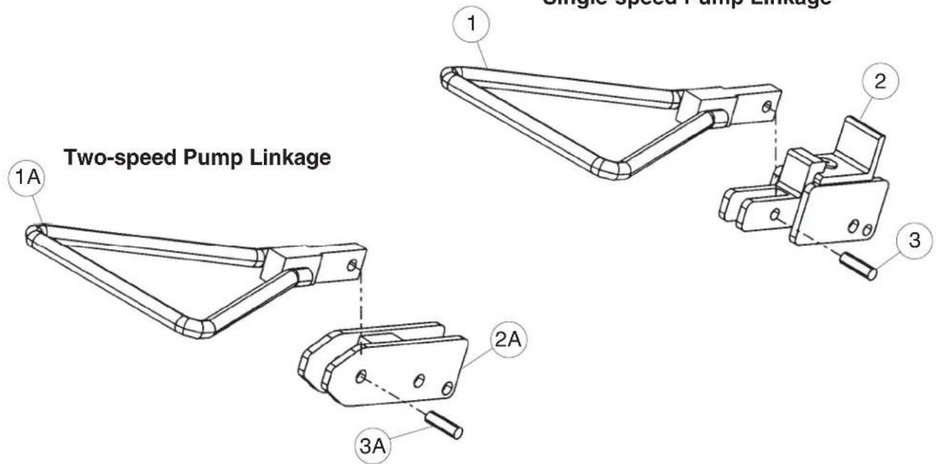
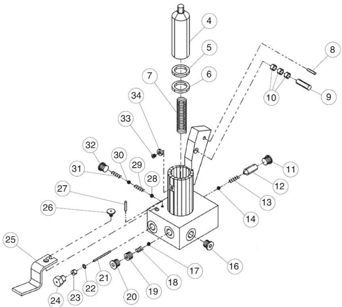
Parts Identification for Single and Two-speed Hydraulic Foot Pump
| DESCRIPTION | PART NO. | QTY | |
| 1 | Assembly, lever delta foot pedal, double speed | 01-540-003 | 1 |
| 1A | Assembly, lever delta foot pedal, single speed | 01-540-004 | 1 |
| 2 | Linkage for single-speed foot pump | NFP-LNK1 | 1 |
| 2A | Linkage for two-speed foot pump | NFP-LNK2 | 1 |
| 3 | 3/8" x 1-3/4" dia. detent pin | 01-130-004 | 1 |
| 3A | 3/8" x 1-1/4" dia. detent pin | 01-130-005 | 1 |
| 4 | Pump plunger | 01-041-0041 | 1 |
| B 5 | Piston wiper seal | 550110 | 1 |
| B 6 | Piston U-cup seal | 532101 | 1 |
| 7 | Piston return spring | 01-146-004 | 1 |
| 8 | 1/4" x 1-1/2" spring pin | 64251 | 1 |
| 9 | 3/8" x 1-3/4" dia. Drive-Lock pin | 01-130-004 | 1 |
| 10 | Sleeve sintered bronze bearing | 01-111-038 | 3 |
| 11 | Fitting, "O"-ring plug | 01-116-007 | 1 |
| 12 | Pressure compensated flow control valve | 01-127-007 | 1 |
| 13 | Release check spring | 01-146-002 | 1 |
| 14 | 5/16" dia. steel ball | 01-145-001 | 1 |
| 15 | Pump body | NFP-BDYMAN | 1 |
| 16 | Fitting, "O"-ring plug | 01-116-007 | 1 |
| 17 | 3/8" dia. chrome steel ball | 01-145-003 | 1 |
| 18 | Pressure relief spring | 01-146-005 | 1 |
| B 19 | Fitting, pressure adjustment plug | 01-116-006 | 1 |
| 20 | Fitting, "O"-ring plug | 01-116-007 | 1 |
| 21 | Release pin | 01-112-016 | 1 |
| B 22 | Release pin seal retaining ring | 565011 | 1 |
| B 23 | Release rod U-cup seal | 01-144-002 | 1 |
| 24 | Fitting, hydraulic plug | 01-116-004 | 1 |
| 25 | Release lever | 01-040-001 | 1 |
| 26 | Release lever retaining screw | 01-119-001 | 1 |
| 27 | 3/16" x 1-1/8" spring pin | 64134 | 1 |
| 28 | 5/16" dia. chrome steel ball | 01-145-001 | 1 |
| 29 | Inlet check spring | 01-146-001 | 1 |
| 30 | 7/16" dia. chrome steel ball | 01-145-004 | 1 |
| 31 | Outlet check spring | 01-146-001 | 1 |
| 32 | Fitting, "O"-ring plug | 01-116-007 | 1 |
| 33 | 1/4" -20 x 1/4" socket head cap screw | 562008 | 1 |
| B 34 | 1/4" sealing washer (copper with rolled core) | 577004 | 1 |
| B | Foot Pump rebuild kit (includes items 5,6,19,22,23,34) | 01-136-403 | 1 |

Kit item (included with purchase of
kit)
A/L Available at local hardware store
Note: Please provide serial number of lift when ordering replacement parts.
TROUBLESHOOTING GUIDE - HDC-305
Before performing any task, always lower the carrier fully to the floor and disconnect the power supply.
Consult the factory for problems at time of installation, or for any problems not addressed below.
*Check the DC notes page for troubleshooting other problems specific to battery-powered units.
| Possible Cause(s) | ActionProblem | |
| Power unit doesn't run when "UP" button is pressed. | Transformer fuse is blown.No supply voltage. | Test with meter; replace if bad.Test with meter. Check fuses, break-ers, and overloads to determine the cause. |
| Upper-travel limit switch is engaged or bad. | Inspect and test switch. Replace if bad | |
| Bad connection in control circuit. | Test all parts of circuit with meter. | |
| Bad control transformer. | Check for 24 VAC; replace if bad. | |
| Open motor relay coil. | Test with meter; replace if bad. | |
| Battery voltage low. | Test with meter. Charge battery if low (is motor relay LED on?) | |
| Motor runs properly, carrier doesn't move. Motor and pump not noisy. | Motor rotation is wrong. | Verify motor shaft rotates CCW. |
| Pump has failed. | Consult factory for replacement. | |
| Fluid level is low. | Ensure reservoir is filled. | |
| Motor or control enclosure hums, chatters, or buzzes, or some type of squeal can be heard; the carrier does not move, or the carrier moves only slowly. | See second item above, for when carrier doesn't raise. | Same as above. |
| Excess voltage drop to motor, due to power wire size too small, wire run to long, or incoming voltage too low. | Check power installation for adequacy. Check incoming voltage while motor is running. Correct problem found. | |
| Motor is "single-phasing". | Determine cause of loss of voltage on one phase; correct. | |
| Pressure relief opening a full pressure. | Check for structural damage or binding of the scissor legs, etc. Check for carrier overload condition. | |
| Contamination holding open the lowering valve or the check valve. | Remove and inspect. Clean per instructions in this manual. | |
| Carrier raises, then drifts down. | See last paragraph, above. | Same as above. |
| Carrier lowers too quickly. | See above. | Same as above. |
| Flow control spool is stuck. | See below. | |
| Carrier lowers too slowly. | Flow control spool is stuck. | Remove plug from FC port; push on flow spool to ensure it is fully pressed into the cavity. |
| Pinched hose. | Check pressure, supply, and return hoses for kinks. | |
| Velocity fuse locking (carrier only slowly creeps down). | Same as for jerky carrier motion. | |
| Carrier won't lower. | Velocity fuse locking. | Same as for jerky carrier motion. |
| Control transformer fuse blown. | Test with meter; replace if bad. | |
| No supply-voltage. | Test with meter. Check for cause of power loss. | |
| Valve solenoid is bad. | Check with multimeter on diode-check function. (Reading for ohms will not provide an accurate test of the coil.) | |
| Bad connection in control circuit. | Test all parts of circuit with meter. | |
| Physical blockage of the structure. | Inspect for foreign material or objects that might block the leg set or its rollers. | |
| Solenoid valve or suction hose screen plugged. | Remove and inspect. Clean per instructions in this manual. | |
| Spongy or jerky carrier motion. | Excessive air in the hydraulic cylinder. | Bleed air per procedure described in manual |
Warning Label Identification

E
(on rear panel of power unit)
D: Label #203-1


C
A: Label #220
| WARNING | ADVERTENCIA | AVERTISSEMENT |
| KEEP CLEARWHEN IN USE | MANTENGASEALEJADO CUANDO SEESTA OPERANDO | SE TENIR ÀDISTANCE LORS DUFONCTIONNEMENT220 Rev. 08/03 |
B: Label #232
| CAUTION | ATENCIÓN | ATTENTION |
| DRUM MUST BE INVERTICAL POSITIONWHEN MOVING | EL TAMBOR DEBE DE ESTAREN LA POSICIÓN VERTICALCUANDO EN MOVIMIENTO | LE BIDON DOIT ÊTRE ENPOSITION VERTICALELORS D'UN DÉPLACEMENT |
C: Label #206
| ISO 32 / 150 SUS |
| HYDRAULIC OIL OR NON-SYNTHETIC TRANSMISSION FLUID |
| ACEITE HIDRAULICO O LIQUIDOS DETRANSMISION NO SINTETICOS |
| HUILE OU LIQUIDE HYDRAULIQUE NON-SYNTHÉTIQUE |
E: Label #295
WARNING
Enclosed battery contains hazardous chemicals.
DO NOT handle enclosed battery UNLESS wearing eye protection and other appropriate personnel protective equipment.
DO NOT directly contact skin with battery.
DO NOT expose to sparks or extreme heat; battery contains explosive gases.
ADVERTENCIA
Vestil Manufacturing Corporation ("Vestil") warrants this product to be free of defects in material and workmanship during the warranty period. Our warranty obligation is to provide a replacement for a defective original part, if the part is covered by the warranty, after we receive a proper request from the warrantee (you) for warranty service.
Who may request service?
Only a warrantee may request service. You are a warrantee if you purchased the product from Vestil or from an authorized distributor AND Vestil has been fully paid.
What is an "original part"?
An original part is a part used to make the product as shipped to the warrantee.
What is a "proper request"?
A request for warranty service is proper if Vestil receives: 1) a photocopy of the Customer Invoice that displays the shipping date; AND 2) a written request for warranty service including your name and phone number. Send requests by any of the following methods:
| Fax | ||
| Vestil Manufacturing Corporation | (260) 665-1339 | sales@vestil.com |
| 2999 North Wayne Street, PO Box 507 | Phone | |
| Angola, IN 46703 | (260) 665-7586 |
In the written request, list the parts believed to be defective and include the address where replacements should be delivered.
What is covered under the warranty?
After Vestil receives your request for warranty service, an authorized representative will contact you to determine whether your claim is covered by the warranty. Before providing warranty service, Vestil may require you to send the entire product, or just the defective part or parts, to its facility in Angola, IN. The warranty covers defects in the following original dynamic components: motors, hydraulic pumps, electronic controllers, switches and cylinders. It also covers defects in original parts that wear under normal usage conditions (“wearing parts”): bearings, hoses, wheels, seals, brushes, batteries, and the battery charger.
How long is the warranty period?
The warranty period for original dynamic components is 1 year. For wearing parts, the warranty period is 90 days. Both warranty periods begin on the date when Vestil ships the product to the warrantee. If the product was purchased from an authorized distributor, the periods began when the distributor shipped the product. Vestil may extend the warranty period for products shipped from authorized distributors by up to 30 days to account for shipping time.
If a defective part is covered by the warranty, what will Vestil do to correct the problem?
Vestil will provide an appropriate replacement for any covered part. An authorized representative of Vestil will contact you to discuss your claim.
What is not covered by the warranty?
- Labor;
- Freight;
- Occurrence of any of the following, which automatically voids the warranty:
• Product misuse;
- Negligent operation or repair;
• Corrosion or use in corrosive conditions;
- Inadequate or improper maintenance;
• Damage sustained during shipping;
• Accidents involving the product;
- Unauthorized modifications: DO NOT modify the product IN ANY WAY without first receiving written authorization from Vestil. Modification(s) might make the product unsafe to use or might cause excessive and/or abnormal wear.
Do any other warranties apply to the product?
Vestil Manufacturing Corp. makes no other express warranties. All implied warranties are disclaimed to the extent allowed by law. Any implied warranty not disclaimed is limited in scope to the terms of this Limited Warranty.


- VESTIL MANUFACTURING CORPORATION
- OWNER'S
- MANUAL
- CONTENTS
- WARNINGS & SAFETY INSTRUCTIONS
- READ OWNER'S MANUAL COMPLETELY BEFORE OPERATING UNIT
- RECEIVING INSTRUCTIONS
- OPERATING INSTRUCTIONS
- LOADING
- OPERATION: TO LIFT
- POWERED UNITS
- TO RAISE
- SAFETY
- ORDERING REPLACEMENT OR EXTRA PARTS
- ADDITIONAL INSTRUCTIONS FOR BATTERY-POWERED UNITS
- WARNING
- BATTERY CHARGER OPERATING INSTRUCTIONS
- TROUBLESHOOTING
- ROUTINE MAINTENANCE & SAFETY CHECKS
- BEFORE EACH USE INSPECT ANY AND ALL SAFETY DEVICES
- MONTHLY INSPECTIONS
- YEARLY INSPECTION
- THE POWER UNIT'S OPERATION - HDC-305
- AC-POWERED HDC-305 ELECTRICAL SYSTEM DIAGRAM
- DANGER
- HYDRAULIC DIAGRAM - HDC-305
- PARTS DIAGRAM FOR SINGLE AND TWO-SPEED HYDRAULIC FOOT PUMPS
- E: LABEL #295
- ADVERTENCIA
- WHO MAY REQUEST SERVICE
- WHAT IS AN "ORIGINAL PART
- WHAT IS A "PROPER REQUEST
- WHAT IS COVERED UNDER THE WARRANTY
- HOW LONG IS THE WARRANTY PERIOD
- IF A DEFECTIVE PART IS COVERED BY THE WARRANTY, WHAT WILL VESTIL DO TO CORRECT THE PROBLEM
- WHAT IS NOT COVERED BY THE WARRANTY
- DO ANY OTHER WARRANTIES APPLY TO THE PRODUCT
Brand : Vestil
Model : HDC-305-84
Category : Appareil de manutention hydraulique