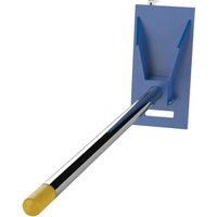
CR-60-3 - Handling tool Vestil - Free user manual and instructions
Find the device manual for free CR-60-3 Vestil in PDF.


| Product Type | Utility Cart / Hand Truck |
| Brand | Vestil |
| Model | CR-60-3 |
| Capacity (Weight Limit) | 60 lb (27 kg) |
| Overall Dimensions | 45" L x 20" W x 36" H (1143 x 508 x 914 mm) |
| Platform Dimensions | 30" L x 20" W (762 x 508 mm) |
| Handle Height | 36" (914 mm) |
| Wheel Diameter | 6" (152 mm) |
| Wheel Type | Swivel casters (front), rigid (rear) |
| Weight | 35 lb (15.9 kg) |
| Material | Steel frame, plastic platform |
| Color | Blue |
| Assembly Required | Yes |
| Warranty | 1 year limited |
| Maintenance | Keep clean, lubricate wheels |
| Safety | Load evenly, do not exceed capacity |
| Use | For transporting boxes, equipment |
Frequently Asked Questions - CR-60-3 Vestil
User questions about CR-60-3 Vestil
0 question about this device. Answer the ones you know or ask your own.
Ask a new question about this device
Download the instructions for your Handling tool in PDF format for free! Find your manual CR-60-3 - Vestil and take your electronic device back in hand. On this page are published all the documents necessary for the use of your device. CR-60-3 by Vestil.
USER MANUAL CR-60-3 Vestil
Vestil Manufacturing Company
2999 North Wayne Street, P.O. Box 507, Angola, IN 46703
Telephone: (260) 665-7586 -or- Toll Free (800) 348-0868
Fax: (260) 665-1339
Web: www.vestil.com e-mail: info@vestil.com
CR-series Carpet Poles

Receiving Instructions
After delivery, remove the packaging from the product. Inspect the product closely to determine whether it sustained damage during transport. If damage is discovered, record a complete description of it on the bill of lading. If the product is undamaged, discard the packaging.
NOTE: The end-user is solely responsible for confirming that product design, use, and maintenance comply with laws, regulations, codes, and mandatory standards applied where the product is used.
Technical Service & Replacement Parts
For answers to questions not addressed in these instructions and to order replacement parts, labels, and accessories, call our Technical Service and Parts Department at (260) 665-7586. The department also be contacted online at https://www.vestil.com/page-parts-request.php.
Electronic copies of Instruction Manuals
Additional copies of this instruction manual may be downloaded from https://www.vestil.com/page-manuals.php.
| Table of Contents | Page |
| Signal Words | 2 |
| Safety Instructions | 2 |
| Specifications | 3 |
| CR (class 2 carriage) Exploded View & Bill of Materials | 4 |
| CR (class 3 carriage) Exploded View & Bill of Materials | 5 |
| Attaching the Carpet Pole to a Lift Truck Carriage | 6 |
| National Standards | 7 |
| Using the Carpet Pole | 7 |
| Record of Satisfactory Condition | 7 |
| Inspecting the Carpet Pole | 7 - 8 |
| Maintaining the Carpet Pole | 8 |
| Labeling Diagram | 9 |
| Limited Warranty | 10 |
SIGNAL WORDS
SIGNAL WORDS appear in this manual to draw the reader's attention to important safety-related messages. The following are signal words used in this manual and their definitions.

DANGER

WARNING

CAUTION
NOTICE
Identifies a hazardous situation which, if not avoided, WILL result in DEATH or SERIOUS INJURY. Use of this signal word is limited to the most extreme situations.
Identifies a hazardous situation which, if not avoided, COULD result in DEATH or SERIOUS INJURY.
Indicates a hazardous situation which, if not avoided, COULD result in MINOR o MODERATE injury.
Identifies practices likely to result in product/property damage, such as operations that might damage the product.
SAFETY INSTRUCTIONS
Vestil strives to identify foreseeable hazards associated with the use of its products, but no manual can address every conceivable risk. Minimize the likelihood of injury by observing the hazards identified below and by inspecting and maintaining the product as instructed in the INSPECTIONS and MAINTENANCE sections of this manual on p. 6-7.
WARNING
Risks of serious personal injuries or death. Always apply material handling techniques learned during training and use the product properly.
- Read and understand the entire manual before assembling, using or servicing the product.
- Before using this (forklift) front end attachment, you must contact the manufacturers of all forklifts that will use it to request: 1) written approval; and 2) markings for each forklift that identify the coil carrier AND give the approximate weight of the forklift and carrier at maximum elevation with a laterally-centered load. DO NOT use the carpet pole until all forklifts are appropriately marked.
- Read and understand the entire manual before installing, using, or servicing the product. Read the manual to refresh your understanding of proper use, inspection, and maintenance procedures whenever necessary.
• DO NOT exceed the capacity of your unit. See LABELING DIAGRAM, label 1153, p. 9.
- Inspect the carpet pole before each use as described in INSPECTING THE CARPET POLE on p. 7-8.
- Before attaching the carpet pole to the carriage of your fork lift, inspect the carriage and confirm that all parts are structurally sound and in satisfactory condition. See RECORD OF SATISFACTORY CONDITION on p. 6.
- Always connect the safety chain to the carriage of your forklift without slack. The unit must not be able to slide on the forks.
- Verify that the load is stable by lifting the carpet just a few inches above the ground. Load swing should be minimal and the carpet pole should not shift on the forks. If the load is not stable while elevated, return it to the ground and use another device to transport it.
- ALWAYS apply the rules governing use of (forklift) front end attachments applied at your work site.
- DO NOT cover or remove any label. Verify the location and legibility of all labels. Label placement is shown in the LABELING DIAGRAM on p. 9. DO NOT use this device UNLESS all product labels are readable and undamaged.
• DO NOT ride or sit on the carpet pole.
- DO NOT use the carpet pole to push objects. Only use the product to transport a roll of carpet.
- ONLY use this product when traveling on firm, level, even ground.
- Carpet roll must not be longer than the pole. The carpet roll must not hang over the end of the pole. See USING THE CARPET POLE on p. 7 for loading instructions.
- DO NOT leave elevated rolls of carpet unattended. Always lower the load to the ground before leaving the forklift.
- DO NOT modify the carpet pole in any way UNLESS you first obtain written approval from Vestil. Unauthorized modifications automatically void the LIMITED WARRANTY (p. 10) and might make the product unsafe to use.
SPECIFICATIONS
Documents that provide specifications for CR-series carpet poles are available online to anyone who visits Vestil's website. Specifications include dimensions, net weight, and center of gravity information. To access the appropriate specifications document, navigate to the CR webpage at https://www.vestil.com/product.php?FID=496. Scroll the page to the entry for model you purchased. Click the button in the "PDF" column that looks like a pencil inside a blue box. A PDF file will open. This file is the specifications document. Print a copy of the document and keep it with your copy of this manual. The following is an exemplar specification document, in this case, for model CR-108-3 (08-007-103).
CLASS III CARRIAGE MOUNTED RUG-RAM - CR-108-3
APPROX WEIGHT: 296.10 lbs
DOES NOT INCLUDE WEIGHT OF POWER OR PACKAGING!!
*** ANY ADDITIONS, DELETIONS, OR OMISSIONS MUST BE CORRECTED ON THIS DRAWING AS THIS DRAWING WILL BE CONSIDERED ALL INCLUSIVE *** ALL GRAPHICS PROVIDED ARE FOR REFERENCE ONLY. IF CERTAIN DIMENSIONS ARE CRITICAL PLEASE VERIFY THOSE DIMENSIONS WITH YOUR SALESPERSON

POLE DIMENSION TOLERANCE ± 1/2"
DUE TO VARIATIONS IN FORK TRUCK CARRIAGES, PLEASE HAVE THE CUSTOMER VERIFY THAT THEIR CARRIAGE WILL CONFORM TO THE DIMENSIONS SHOWN TO THE RIGHT. IF NOT, PLEASE HAVE THE CUSTOMER VERIFY DIMENSIONS B, T2, T3 & H4 TO BE ABLE TO QUOTE A SPECIAL BACKPLATE TO FIT.
SPECIAL FEATURES
STANDARD FEATURES
MODEL NUMBER: CR-108-3
CAPACITY: 2,500 LBS. UNIFORM CAPACITY
POLE LENGTH: 108 1/2"
POLE DIAMETER: 2 3/4"
FITS CLASS III CARRIAGE
DURABLE LIQUID PAINT BLUE FRAME
NONE
HORIZONTAL CENTER OF GRAVITY: 36 3/16"
VERTICAL CENTER OF GRAVITY: 9 9/16"
LOST LOAD: 295 LBS. (APPROX.)
NOTE: NEVER EXCEED LOAD CENTER RATING PER
FORK TRUCK MANUFACTURER'S GUIDELINES.
DO NOT USE THIS FORK TRUCK ATTACHMENT
IF LOAD WILL EXCEED FORK TRUCK
MANUFACTURER'S LOAD CENTER RATING.
DIMENSION TOLERANCE ± 1/4"
| I. THE UNDERSIGNED, AGREE THAT THE PRODUCT AS REPRESENTED SATISFIES DESIGN AND DIMENSION REQUIREMENTS. I ALSO ACKNOWLEDGE MY DUTY TO CONFIRM PRODUCT AND INSTALLATION COMPLIANCE WITH ALL APPLICABLE FEDERAL, STATE AND LOCAL REGULATIONS AND STANDARDS. UNITS REQUIRING APPROVAL DRAWINGS OR MODIFIED ARE NON-RETURNABLE [ ] As drawn [ ] As marked | |||
| Signed: Date: | |||
| Printed Name: | |||
| LEAD TIME WILL START UPON RECEIPT OF SIGNED APPROVAL DRAWING |
EXPLODED VIEW OF CR-SERIES CARPET POLE: Class 2 carriage, welded carriage clamp (08-006-100)
Torque specifications for clamp fasteners:
Item no. 2 (pole mounting bolts; 5/8 in. - 11 x 6in. grade 8 SHCS bolt) should be fastened to hex nuts (item no. 3) with 238 ft.*lbs. of torque.
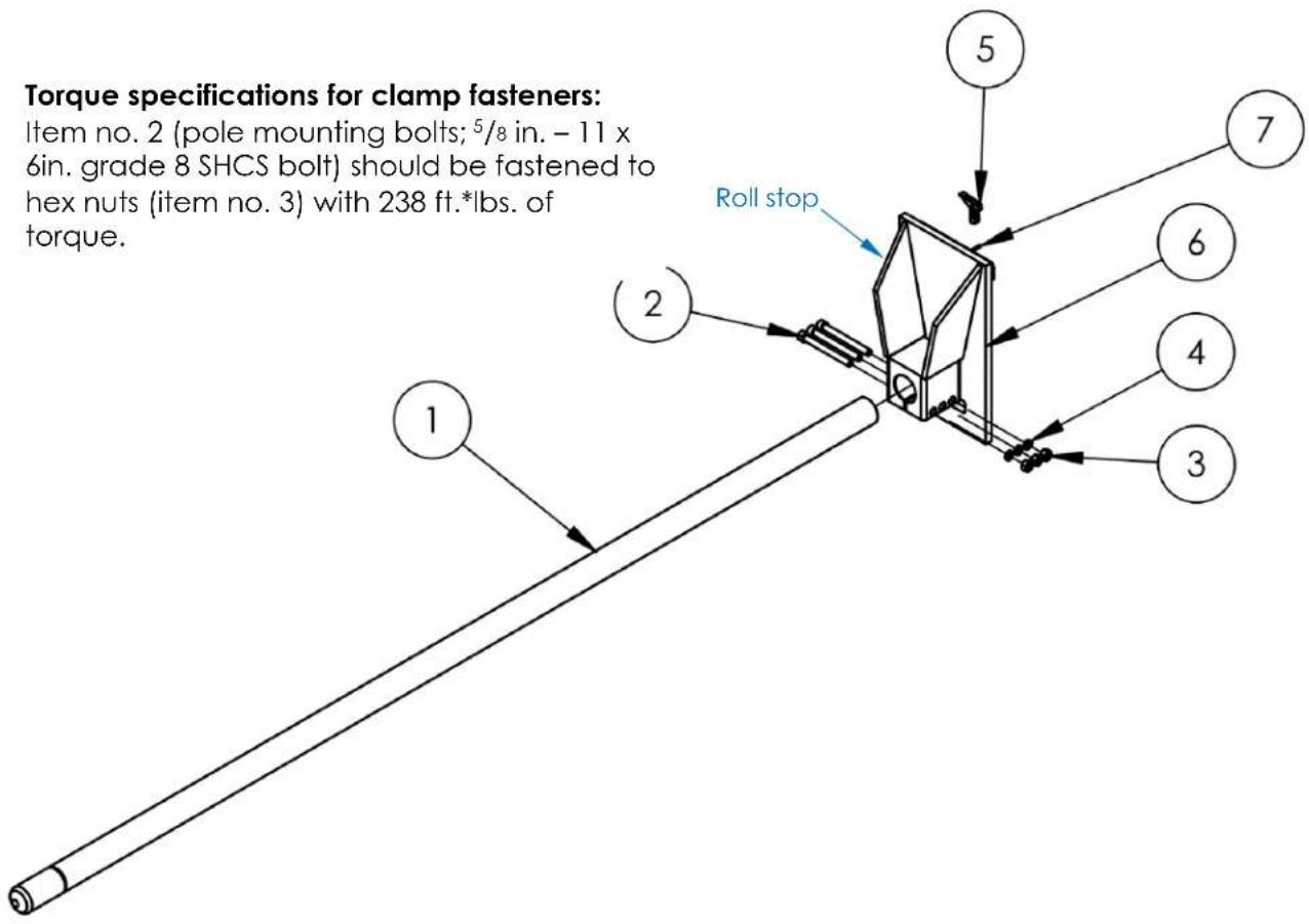
| Item | Part no. | Description | Quantity |
| 1 | Pole weldment: | ||
| 08-514-383 | CR-48-2 (4ft.) | 1 | |
| 08-514-384 | CR-60-2 (5ft.) | 1 | |
| 08-514-385 | CR-96-2 (8ft.) | 1 | |
| 08-514-092 | CR-108-2 (9ft.) | 1 | |
| 08-514-093 | CR-120-2 (10ft.) | 1 | |
| 08-514-094 | CR-144-2 (12ft.) | 1 | |
| 2 | 23525 | 5/8 in. – 11 x 6in. grade 8 SHCS bolt | 3 |
| 3 | 36414 | 5/8 in. – 11 grade 8 UNC hex nut | 3 |
| 4 | 33692 | 5/8 in. high collar lock washer | 3 |
| 5 | 08-154-004 | Locking mechanism kit | 1 |
| 6 | 08-538-001-002 | Carriage back plate weldment | 1 |
| 7 | 40580 | M5 x 32mm heavy duty plain finish metric spring pin | 1 |
EXPLODED VIEW OF CR-SERIES CARPET POLE: Class 3 carriage, welded carriage clamp (08-006-103)
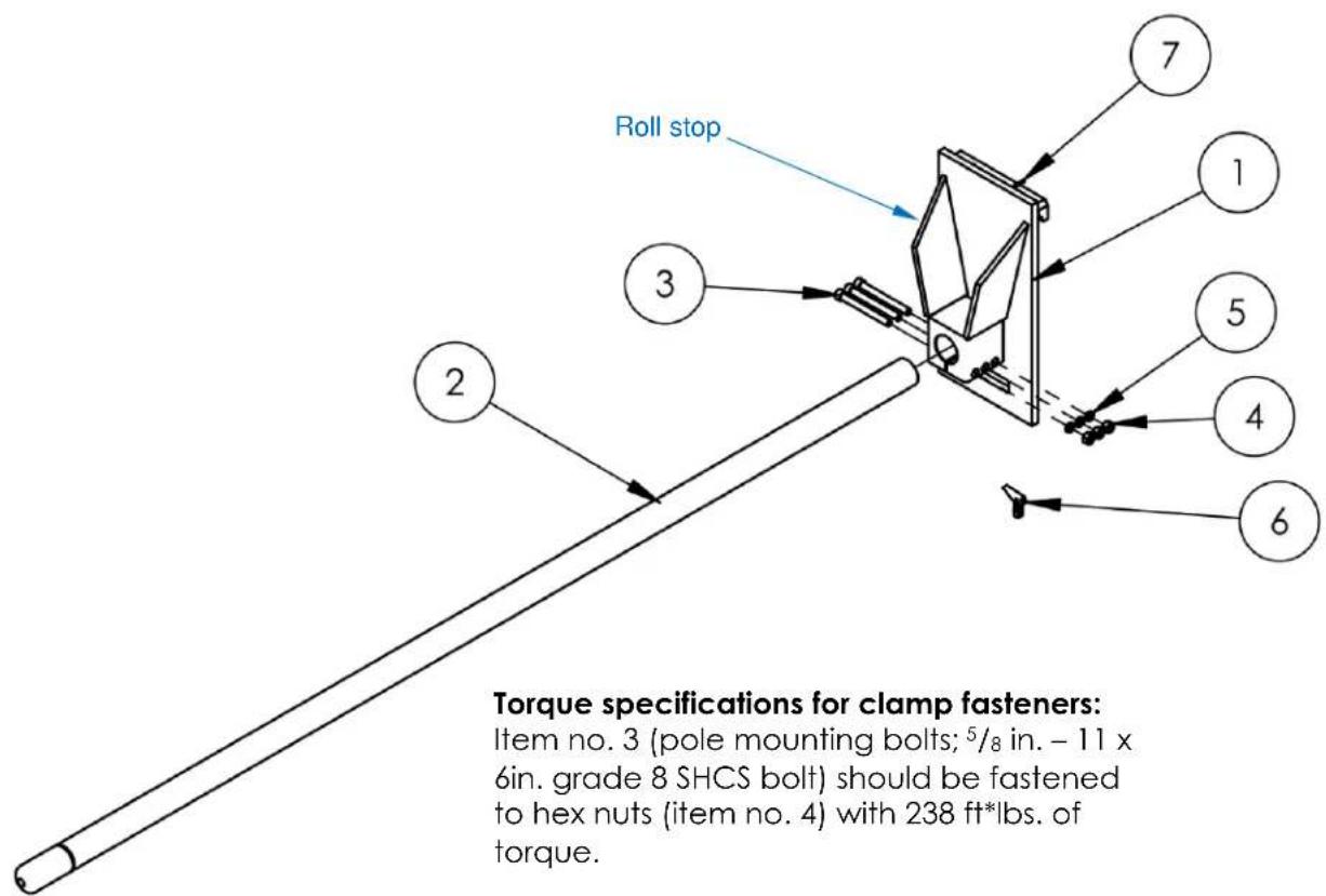
| Item | Part no. | Description | Quantity |
| 1 | 08-538-002 | Carriage back plate weldment | 1 |
| 2 | Pole weldment: | ||
| 08-514-383 | CR-48-3 (4ft.) | 1 | |
| 08-514-384 | CR-60-3 (5ft.) | 1 | |
| 08-514-385 | CR-96-3 (8 ft.) | 1 | |
| 08-514-092 | CR-108-3 (9ft.) | 1 | |
| 08-514-093 | CR-120-3 (10ft.) | 1 | |
| 08-514-094 | CR-144-3 (12ft.) | 1 | |
| 3 | 23525 | 5/8 in. – 11 x 6in. grade 8 SHCS bolt | 3 |
| 4 | 36414 | 5/8 in. – 11 grade 8 UNC hex nut | 3 |
| 5 | 33692 | 5/8 in. high collar lock washer | 3 |
| 6 | 08-154-004 | Locking mechanism kit | 1 |
| 7 | 40580 | M5 x 32mm heavy duty plain finish metric spring pin | 1 |
ATTACHING THE CARPET POLE TO A LIFT TRUCK CARRIAGE
Step 1: Remove the tines from the lift truck carriage.
Step 2: Referring to the diagram below, rotate the latch lever to the open position. Set the left side of the upper carriage bracket on the upper carriage crossbar of your lift truck.
Right side
Turn latch lever to open position (shown closed)
Upper carriage bracket
Set the upper carriage bracket on the carriage crossbar of your forklift. Then, slide the bracket along the carriage crossbar until the lower carriage bracket fits into the notch in the lower carriage crossbar of your forklift.
Carpet pole back

NOTE: The latch can be attached to either the left or right side of the upper bracket (shown installed on left side).
Left side
Step 3: Slide the upper carriage bracket along the carriage crossbar. Adjust position to allow the lower carriage bracket to fit into the notch in the lower carriage crossbar (of the forklift). The notch is probably located at the center of the crossbar. Next, slide the back plate to the left or right as necessary to center the carpet pole on the carriage.
Step 4: Secure the carpet pole to the lift truck carriage by closing the latch.
[NOTE: The latch lever will only rotate back to the closed position if the latch aligns with a notch in the upper crossbar. If necessary, adjust the position of the pole until the latch aligns with a notch.]
NATIONAL STANDARDS
According to US Federal Occupational Safety and Health Administration (OSHA) Rule 1910.178 (29 CFR 1910.178; the "Rule"), this device is a front end attachment for a lift truck whenever it is mounted on the carriage of a lift truck. The Rule incorporates American National Standard ANSI/ITSDF B56.1 (the "Standard") published by the Industrial Truck Standards Development Foundation (ITSDF) on its website (www.itsdf.org). The standard is freely downloadable at http://www.itsdf.org/cue/b56-standards.html. Before putting this carpet pole into service, you must acquire a copy of the Standard. Apply all relevant parts of Part II: For the User. Lift truck users must mark/label the truck to identify the carpet pole, show the weight of the truck and pole combination, and show the capacity of the truck with the pole at maximum elevation with the load laterally centered. If instructions in this manual conflict with instructions in the Standard then the instructions in the Standard should be applied. Please contact our TECHNICAL SERVICE department if you believe that these instructions conflict with the Standard. Contact information for TECHNICAL SERVICE appears on the cover page of this manual.
USING THE CARPET POLE
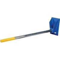
Step 1: Insert the pole into the core of a roll of carpet. Drive forward until the end of the roll contacts the receiver. The yellow end of the pole must extend beyond the end of the roll. Do not use the carpet pole to lift and/or move a carpet roll unless the pole is long enough to extend beyond the end of the carpet roll.
Step 2: Raise the forks only as high as necessary to lift the roll of carpet off of the ground and to avoid contact with objects during transport. Always watch and listen to the pole for abnormalities during use. DO NOT leave a raised roll unattended. Always unload the carpet pole before leaving the forklift.
RECORD OF SATISFACTORY CONDITION
Before using the carpet pole for the first time, make a written record of its appearance. Describe the condition of the frame, pole, carriage brackets, and the latch. Take photographs and/or videos of all features. Make sure that all features are clearly captured in your photos/videos. Similarly record all labels applied to the carpet pole in such a way that the labels can be clearly seen as can their locations. Collect all photos, videos, and writings in a file. The file is a record of the unit in satisfactory condition. When conducting any inspection, compare your observations to the record to determine if the unit is in satisfactory condition. Do not use the carpet pole unless every component is in satisfactory condition. Cosmetic changes, like damaged paint/powder coat or superficial rust, do not constitute changes from satisfactory condition. However, touchup paint should be applied to all affected areas that previously were painted/powder coated as soon as damage occurs.
INSPECTING THE CARPET POLE
Inspections and repairs should only be performed by qualified persons. Compare the results of each inspection to the RECORD OF SATISFACTORY CONDITION (the "RECORD"). Do not use the carpet pole unless all parts are in satisfactory condition. Replace parts that are not in satisfactory condition before returning the pole to service. DON'T GUESS! If you have any questions about the condition of your carpet pole, contact the TECHNICAL SERVICE department. The phone number is provided on the cover page of this manual. Never make temporary repairs of damaged or missing parts. Only use manufacturer-approved replacement parts. Replace the entire unit if it cannot be restored to satisfactory condition.
Before each use, perform the following inspections:
-
Check the surface of the pole for dirt, oil, or other matter.
-
Examine hardware & fasteners, including but not limited to bolts, nuts, pins, and latch. Look for cracks, bends, significant rust or corrosion. Tighten loose fasteners. Replace damaged fasteners.
- Examine pole, back plate weldment, and pole clamp for looseness or excessive wear, corrosion/rusting, metal fatigue, and other forms of damage (e.g. impact damage). Confirm that the pole mounting bolts and nuts are tightened to the torque specification provided in the applicable EXPLODED VIEW on either p. 4 or p. 5.
- Confirm that the carriage brackets are in satisfactory condition.
- Check all labels. Replace labels that are damaged or not easily readable (e.g. faded). Refer to the LABELING DIAGRAM on p. 9.
- Examine the whole structure for rusting/metal erosion. Remove rust/corrosion with a mild abrasive or steel wool. Clean the area and apply touchup paint if the affected area was previously painted. For stainless steel surfaces, after removing rust, apply a thin layer of oil to the affected area.
Annual evaluation — At least once per year, qualified inspection personnel should use the carpet pole to list a full capacity load. Afterwards, conduct a Before Each Use Inspection to confirm that the product is in satisfactory condition.
MAINTAINING THE CARPET POLE
Implement a maintenance program to ensure that the product functions properly and is adequately maintained. The OSHA "General Industry" standard for "Powered industrial trucks" (29 CFR 1910.178) provides recommended maintenance procedures. The following steps should be utilized in conjunction with those procedures. ONLY trained, authorized personnel or contractors should perform inspection, maintenance, or repair work.
NOTE: It is the end-user's responsibility to select and train employees to work with/on (assemble, use, inspect, and maintain) the carpet pole.
Step 1: Tag the pole, "Out of Service."
Step 2: Remove any dirt or other matter from all surfaces.
Step 3: Conduct a "Before each use" inspection. DO NOT use the product if you discover damage that compromises the structural integrity of the pole. Such damage includes, but is not limited to, severe rusting/corrosion that has eroded metal from weight-bearing members). Permanently remove it from service.
Step 4: Perform all necessary adjustments, replacements and/or repairs but DO NOT modify the pole.
NOTE: There are significant differences between necessary adjustments/repairs and modifications. An “adjustment” is a simple correction that restores the device to satisfactory condition, such as tightening loose fasteners, or removing dirt or other debris from the surface. “Repair” refers to removing worn parts and installing replacement parts. A “modification” is a change that alters the carpet pole from its original condition, like bending the structural members or removing a part or several parts. NEVER modify the device without first obtaining express, written approval from Vestil. Modifications automatically void the LIMITED WARRANTY (see p. 10) and might make the device unsafe to use.
Step 5: Make a dated record of all repairs, adjustments and/or replacements performed.
LABELING DIAGRAM
The unit should be labeled as shown in the diagram. Label content and location are subject to change so your product might not be labeled exactly as shown. Compare this diagram to your RECORD OF SATISFACTORY CONDITION. Replace all labels that are damaged, missing, or not easily readable (e.g. faded). Order replacement labels by contacting the TECHNICAL SERVICE & PARTS DEPARTMENT online at https://www.vestil.com/page-parts-request.php. Alternatively, you may request replacement parts and/or service by calling (260) 665-7586 and asking the operator to connect you to the PARTS DEPARTMENT.
A: Label 985
B: Label 1153; Model, serial no. capacity
| MODEL/MODÉLO/MODELE | |
| STATIC CAPACITY (evenly distributed) | Ibs. |
| LA CAPACIDAD CONSTANTE (distribuida uniformemente) | kgs. |
| CAPACITÉ STATIQUE (distribuée régulièrement) | kgs. |
| SERIAL/SERIE/SÉRIE | |
C: Label 1049
▲ WARNING
Improper use of this fork attachment might result in death or serious injury.
- Before using this fork attachment, US Federal regulation 29 CFR 1910.178 requires you to contact the manufacturer of your lift truck and request:
1. Willen approval [29 CFR 1910.178(a)(4)]
2. Markings for (fork) lift truck that:
- Identify the attachment:
- Give approximate weight of truck and attachment at maximum evaluation with laterally-centered load. [29 CFR 1910.178(s)(5)].
• DO NOT use UNTIL lift truck is marked with corrected capacity tags. 1949
D: Label 1001 (on top)
USE THIS SIDE UP ONLY
E: Label 1049 (Forklift must be marked to identify carpet pole)
▲WARNING
Improper use of this fork attachment might result in death or serious injury.
Before using this fork attachment, US Federal regulation 29 CFR 1910.178 requires you to contact the manufacturer of your lift truck and request:
1. Written approval [29 CFR 1910.178(a)(4)]
2. Markings for (fork) lift truck that:
- Give approximate weight of truck and attachment at maximum evaluation with laterally-centered load. [29 CFR 1910.178(a)(5)]
DO NOT use UNTIL lift truck is marked with corrected capacity tags. 1048
LIMITED WARRANTY
Vestil Manufacturing Company ("Vestil") warrants this product to be free of defects in material and workmanship during the warranty period. Our warranty obligation is to provide a replacement for a defective, original part covered by the warranty after we receive a proper request from the Warrantee (you) for warranty service.
Who may request service?
Only a warrantee may request service. You are a warrantee if you purchased the product from Vestil or from an authorized distributor AND Vestil has been fully paid.
Definition of "original part"?
An original part is a part used to make the product as shipped to the Warrantee.
What is a "proper request"?
A request for warranty service is proper if Vestil receives: 1) a photocopy of the Customer Invoice that displays the shipping date; AND 2) a written request for warranty service including your name and phone number. Send requests by one of the following methods:
US Mail____ Fax Email
Vestil Manufacturing Company
2999 North Wayne Street, PO Box 507
Angola, IN 46703
(260) 665-1339
Phone
(260) 665-7586
info@vestil.com
Enter "Warranty service request"
in subject field.
In the written request, list the parts believed to be defective and include the address where replacements should be delivered. After Vestil receives your request for warranty service, an authorized representative will contact you to determine whether your claim is covered by the warranty. Before providing warranty service, Vestil will require you to send the entire product, or just the defective part (or parts), to its facility in Angola, IN.
What is covered under the warranty?
The warranty covers defects in the following original, dynamic parts: motors, hydraulic pumps, electronic controllers, switches, and cylinders. It also covers defects in original parts that wear under normal usage conditions ("wearing parts"), such as bearings, hoses, wheels, seals, brushes, and batteries.
How long is the warranty period?
The warranty period for original dynamic components is 90 days. For wearing parts, the warranty period is 90 days. Both warranty periods begin on the date Vestil ships the product to the Warrantee. If the product was purchased from an authorized distributor, the periods begin when the distributor ships the product. Vestil may, at its sole discretion, extend a warranty period for products shipped from authorized distributors by up to 30 days to account for shipping time.
If a defective part is covered by the warranty, what will Vestil do to correct the problem?
Vestil will provide an appropriate replacement for any covered part. An authorized representative of Vestil will contact you to discuss your claim.
What is not covered by the warranty?
The Warrantee (you) are responsible for paying labor costs and freight costs to return the product to Vestil for warranty service.
Events that automatically void this Limited Warranty.
- Misuse;
- Negligent assembly, installation, operation or repair;
• Installation/use in corrosive environments; - Inadequate or improper maintenance;
• Damage sustained during shipping;
• Collisions or other accidents that damage the product; - Unauthorized modifications: Do not modify the product IN ANY WAY without first receiving written authorization from Vestil.
Do any other warranties apply to the product?
Vestil Manufacturing Co. makes no other express warranties. All implied warranties are disclaimed to the extent allowed by law. Any implied warranty not disclaimed is limited in scope to the terms of this Limited Warranty. Vestil makes no warranty or representation that this product complies with any state or local design, performance, or safety code or standard. Noncompliance with any such code or standard is not a defect in material or workmanship.




- VESTIL MANUFACTURING COMPANY
- RECEIVING INSTRUCTIONS
- TECHNICAL SERVICE & REPLACEMENT PARTS
- ELECTRONIC COPIES OF INSTRUCTION MANUALS
- SIGNAL WORDS
- SAFETY INSTRUCTIONS
- WARNING
- SPECIFICATIONS
- STANDARD FEATURES
- EXPLODED VIEW OF CR-SERIES CARPET POLE: CLASS 2 CARRIAGE, WELDED CARRIAGE CLAMP (08-006-100)
- TORQUE SPECIFICATIONS FOR CLAMP FASTENERS
- EXPLODED VIEW OF CR-SERIES CARPET POLE: CLASS 3 CARRIAGE, WELDED CARRIAGE CLAMP (08-006-103)
- ATTACHING THE CARPET POLE TO A LIFT TRUCK CARRIAGE
- NATIONAL STANDARDS
- USING THE CARPET POLE
- RECORD OF SATISFACTORY CONDITION
- INSPECTING THE CARPET POLE
- MAINTAINING THE CARPET POLE
- LABELING DIAGRAM
- C: LABEL 1049
- ▲ WARNING
- D: LABEL 1001 (ON TOP)
- USE THIS SIDE UP ONLY
- E: LABEL 1049 (FORKLIFT MUST BE MARKED TO IDENTIFY CARPET POLE)
- ▲WARNING
- LIMITED WARRANTY
- WHO MAY REQUEST SERVICE
- DEFINITION OF "ORIGINAL PART
- WHAT IS A "PROPER REQUEST
- WHAT IS COVERED UNDER THE WARRANTY
- HOW LONG IS THE WARRANTY PERIOD
- IF A DEFECTIVE PART IS COVERED BY THE WARRANTY, WHAT WILL VESTIL DO TO CORRECT THE PROBLEM
- WHAT IS NOT COVERED BY THE WARRANTY
- EVENTS THAT AUTOMATICALLY VOID THIS LIMITED WARRANTY
- DO ANY OTHER WARRANTIES APPLY TO THE PRODUCT
Brand : Vestil
Model : CR-60-3
Category : Handling tool