
KDPR11 - Industrial oven Doyon - Free user manual and instructions
Find the device manual for free KDPR11 Doyon in PDF.


| Product Type | Commercial Convection Oven |
| Model | KDPR11 |
| Brand | Doyon |
| Dimensions (W x D x H) | 38.5 x 32.5 x 28 inches |
| Weight | 120 lb |
| Power Supply | 208-240 V, 60 Hz, 1-phase, 15 A |
| Main Functions | Baking, roasting, proofing |
| Construction Material | Stainless steel interior and exterior |
| Number of Racks | 4 rack positions |
| Temperature Range | 150°F to 500°F (65°C to 260°C) |
| Control Type | Thermostatic dial with indicator light |
| Safety Features | Temperature limit switch, cool-touch handle |
| Maintenance | Clean with damp cloth; avoid abrasive cleaners |
| Spare Parts Availability | Heating elements, thermostat, door gasket, knobs |
| Repairability | User-serviceable parts with manual instructions |
| Documentation | 32-page user manual in English (PDF available) |
Frequently Asked Questions - KDPR11 Doyon
User questions about KDPR11 Doyon
0 question about this device. Answer the ones you know or ask your own.
Ask a new question about this device
Download the instructions for your Industrial oven in PDF format for free! Find your manual KDPR11 - Doyon and take your electronic device back in hand. On this page are published all the documents necessary for the use of your device. KDPR11 by Doyon.
USER MANUAL KDPR11 Doyon
KDP SERIES INSTALLATION MANUAL
UNIT SERIAL NUMBER
Table of Contents
INTRODUCTION....3
ATTENTION....3
CONSTRUCTION 3
SHIPPING 3
IMPORTANT-RECEPTION OF THE MERCHANDISE....3
INSTALLATION....4
IMPORTANT INSTALLATION AND SERVICE 4
FOR YOUR SAFETY....4
IN GENERAL......4
INSTALLERS....4
TO THE ELECTRICIAN 4
TO THE PLUMBER....4
DISTANCES TO RESPECT ....4
ASSEMBLY 5
Foreword 5
TOOLS REQUIRED....5
KDP SERIES CONFIGURATION DIAGRAMS....6
WALL PANEL CONFIGURATIONS....6
TOP PANEL CONFIGURATIONS ....7
ELECTRICAL PANEL CONFIGURATIONS ....8
REFRIGERATION MODULE PLACEMENT 8
ERECTING WALLS 10
INSTALLING CORNER BRACKETS 13
INSTALLING TOPS 12
INSTALLING ELECTRICAL PANELS....13
INSTALLING REFRIGERATION MODULES (RETARDER MODELS) 15
INSTALLING HEATERS ....16
INSTALLING FANS....18
INSTALLING HUMIDY SYSTEM....19
INSTALLING HUMIDY SYSTEM CONT. 19
INSTALLING DOORS....21
INSTALLING FACADES 22
FINAL INSPECTION....23
OPERATION OF THE PROOFER....24
PROOFER MODE 25
RETARDING MODE 26
AUTOMATIC PROOFING/RETARDING MODE SET UP 27
REAL TIME CLOCK SETUP....28
MAINTENANCE AND CLEANING 29
INTRODUCTION
THE MANUFACTURER SUGGESTS TO READ THIS MANUAL CAREFULLY.
This equipment is manufactured with finest quality material by experienced technicians. Proper installation and maintenance will guarantee a reliable service for years to come.
A nameplate fixed to the side of the proofer specifies the serial number, model number, number of phase, amperage, voltage and frequency.
ATTENTION
DOYON is not responsible for damages to the property or the equipment caused by personnel who is not certified by known organizations. The customer is responsible for finding qualified technicians in electricity and plumbing for the installation of the oven.
CONSTRUCTION
You just bought the most advanced proofer in the world, "DOYON" technology at its best. This proofer is manufactured using the highest quality components and material.
DOYON equipment is designed with parts that are easy to find.
SHIPPING
For your safety, this equipment has been verified by qualified technicians and carefully crated before shipment. The freight company assumes full responsibility concerning the delivery in good condition of the equipment in accepting to transport it.
IMPORTANT-RECEPTION OF THE MERCHANDISE
Take care to verify that the received equipment is not damaged before signing the delivery receipt. If a damage or a lost part is noticed, write it clearly on the receipt. If it is noticed after the carrier has left, contact immediately the freight company in order that they do their inspection.
We do not assume the responsibility for damages or losses that may occur during transportation.
INSTALLATION
IMPORTANT INSTALLATION AND SERVICE
Installation and service must be done by specialized technicians. Contact a certified electrician and plumber for set up.
Furthermore, assembly of the KDP series proofer requires two people to assembly the unit.
FOR YOUR SAFETY
DO NOT STORE OR USE GASOLINE OR OTHER FLAMMABLE VAPORS AND LIQUIDS IN THE VICINITY OF THIS OR ANY APPLIANCE.
IN GENERAL
Take off the packaging material with care. Take off all the material used for packing and accessories.
INSTALLERS
TO THE ELECTRICIAN
Electrical supply installation must be in accordance with the electrical rating on the nameplate. The proofer must be connected to the utility and electrically grounded in conformity to the effective local regulations. If these are not established, the oven must be connected according to the Canadian Electrical Code (CSA-C22.1-XX) or National Electrical Code (NFPA 70-XX). Refer to last edition year for XX
TO THE PLUMBER
IMPORTANT: THIS UNIT NEEDS TO BE INSTALLED WITH ADEQUATE BACKFLOW PROTECTION TO COMPLY WITH APPLICABLE FEDERAL, STATE AND LOCAL CODES.
IMPORTANT: THIS UNIT REQUIRES A SCREEN OF AT LEAST 100 MESH TO BE INSTALLED IMMEDIATELY UPSTREAM OF ALL CHECK VALVE TYPE BACKFLOW PREVENTERS USED FOR WATER SUPPLY PROTECTION. THE SCREEN SHALL BE ACCESSIBLE AND REMOVABLE FOR CLEANING OR REPLACEMENT.
This equipment is to be installed to comply with the applicable federal, state or local plumbing codes.
Connect the humidity system (1/4 tubing) to the cold water distribution network. We highly recommend to use a water softener to eliminate minerals in the water. We suggest you to use CUNO # CFS6135 (Doyon part number PLF240).
DISTANCES TO RESPECT
- 10' ceiling height required for proper airflow and service access.
- Back and sides: 1" clearance.
- Floor: level surface within 1/8" per foot for proper installation. Slope should not exceed 3/4" in all directions.
ASSEMBLY
Foreword
Our proofers are constructed of modular panels that interlock together allowing for quick construction. It is important to note that when any foam core panels are attached to each other that the locks are firmly engage into the other panel.
TOOLS REQUIRED
- CAULK GUN
• 5/16 ALLEN WRENCH
• 3/16 ALLEN WRENCH - LEVELS
• STUBBY PHILIP SCREW DRIVER
• LONG #2 PHILIPS SCREWDRIVER
• LONG #3 PHILIPS SCREWDRIVER - 5/16 SOCKET/DRIVER
• 7/16 SOCKET/DRIVER - LOCKING PLIERS
- AJUSTABLE WRENCH
• ELECTRIC DRILL - FISH TAPE
KDP SERIES CONFIGURATION DIAGRAMS
WALL PANEL CONFIGURATIONS
SIDE PANELS

TOP PANEL CONFIGURATIONS
PANELS FOR RETARDER UNIT ARE IN PARENTHASIS
| 50039121(50039130)KDP11 | 50039124(50039141)KDP12 | 50039138(50039138) | 50039124(50039141)KDP13 | 50039127(50039127) | 50039138(50039138) | ||||
| 50039122(50039131) | 50039125(50039133)KDP22 | 50039139(50039142) | 50039125(50039133) | 50039128(50039136)KDP23 | 50039139(50039142) | ||||
| 50039123(50039132) | 50039126(50039134)KDP_0206 | 50039140(50039143) | 50039126(50039134)KDP_0206 | 50039129(50039137)KDP_0206KDP33 | 50039140(50039143) |
FRONT
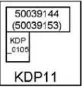
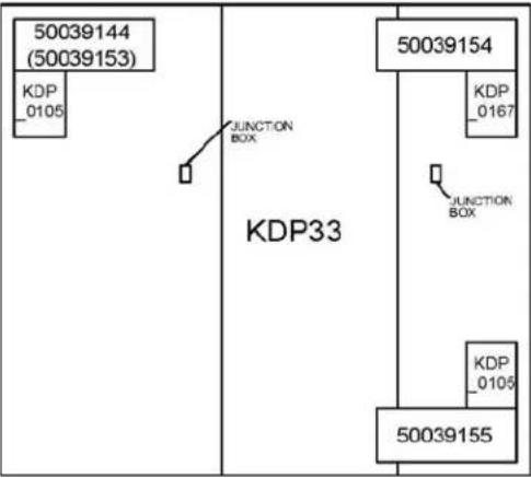
ELECTRICAL PANEL CONFIGURATIONS
 |  |  |
 |  |  |
 |  |  |
FRONT
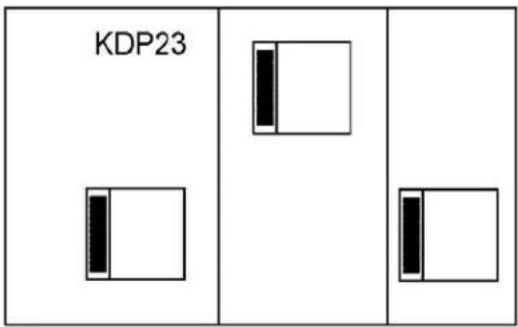
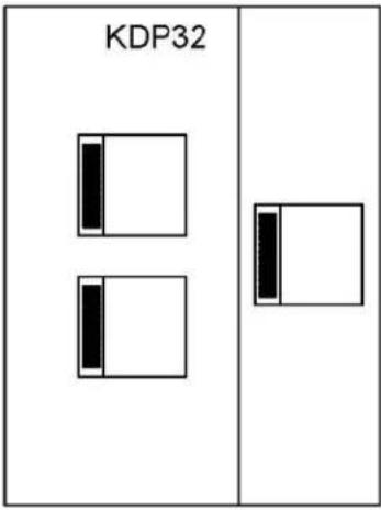
REFRIGERATION MODULE PLACEMENT
 |  |  |
 |  |  |
 |  |  |
FRONT
ERECTING WALLS (NON PASS THRU UNIT)

- WHILE REFFERING TO THE WALL PANEL CONFIGURATIONS DIAGRAM, ERECT THE REAR WALL PANELS FIRST AND LOCK THEM TOGETHER USING A 5/16 HEX WRENCH TO ROTATE THE LOCKS UNTIL THE LOCK ARE ENGAGED.
- AFTER THE REAR PANELS ARE LOCKED, CONTINUE ATTACHING/LOCKING PANELS TILL ALL WALL PANELS ARE ATTACHED.
- AFTER INSTALLING THE HEADER, INSTALL TWO REFORCEMENT BRACKETS, USING FOUR 10-32 HEX HEAD SCREWS EACH, INSIDE OF THE UNIT WHERE THE HEADER AND CORNERS MEET
- WHEN FINISHED ERECTING PANELS, ATTACH INSTALLATION JIG TO THE FRONT CORNERS
ERECTING WALLS (PASS THRU UNIT)

- PASS THROUGH UNITS USE A ADDITIONAL SET OF FRONT PANEL IN THE REAR AS SHOWN IN THE WALL PANEL CONFIGURATIONS DIAGRAM
- WHILE REFFERING TO THE WALL PANEL CONFIGURATIONS DIAGRAM, ERECT THE REAR PANELS FIRST AND LOCK THEM TOGETHER USE A 5/16 HEX WRENCH TO ROTATE THE LOCKS UNTIL THE LOCK ARE ENGAGED.
○ WHEN THE REAR PANELS ARE ERECTED, ATTACH INSTALLATION JIG TO THE REAR CORNERS - AFTER THE REAR PANELS ARE LOCKED AND INSTALLATION JIG INSTALL, CONTINUE ATTACHING/LOCKING PANELS TILL ALL WALL PANELS ARE ATTACHED.
- AFTER INSTALLING THE HEADERS, INSTALL FOUR REFORCEMENT BRACKETS, USING FOUR 10-32 HEX HEAD SCREWS EACH, INSIDE OF THE UNIT WHERE THE HEADERS AND CORNERS MEET
- WHEN FINISHED ERECTING PANELS, ATTACH INSTALLATION JIG TO THE FRONT CORNER.

- WHILE REFFERING TO TOP PANEL CONFIGURATIONS DIAGRAM, INSTALL TOPS AND LOCK TOGETHER
○ START WITH THE REAR PANEL FIRST.
○ MAKE SURE ALL PANEL SURFACES ARE FLUSH WITH ONE ANOTHER
- WHEN DONE
■ FILL LATCH ACCESS HOLES WITH SUPPLIED PLUGS (50-1641)
- USE SUPPLIED SILICONE TO SEAL ALL INTERNAL SEAMS OF THE UNIT
- IF YOUR UNITS IS A KDP(R)32 OR KDP(R)33 INSTALLATION OF REINFORCEMENT BRACES IS NESSECARY AS SHOWN IN THE FIGURE ABOVE
o PART NUMBERS FOR THE BRACES ARE INCLUDED IN THE TOP PANEL CONFIGURATIONS DIAGRAM
- WHEN DONE, USE SUPPLIED SILICONE TO SEAL ALL INTERNAL SEAMS OF THE UNIT
INSTALLING CORNER BRACKETS


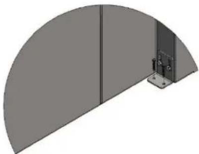
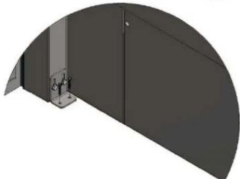
- INSTALL TWO FRONT CORNER BRACKETS (KDP_0050) TO FRONT INNER CORNERS USING TWO 1/4" WASHERS (53-0023) AND TWO 1/4-20 HEX BOLTS (ASBP105) EACH.
o PASS THROUGH UNITS GET ANOTHER SET OF CORNER BRACKETS IN THE REAR
• USINGS THE SUPPLIED MASONARY BIT (51-1407) AND TWO CONCRETE SCREWS (53-0003) DRILL AND SCREW ONE OF THE CORNER MOUNTS TO THE FLOOR.
○ FOR PASS THROUGH UNITS, SCREW THE REAR BRACKET DIAGONALLY ACROSS FROM THE SECURED FRONT BRACKET - AFTER ASSURING THE DOOR FRAME OF THE UNIT IS SQUARE, DRILL AND SCREW (53-0003) THE REMAING CORNER BRACKETS TO THE FLOOR.
- WHEN ALL CORNER BRACKETS ARE SECURED, REMOVE AND DISCARD THE INSTALLATION JIG(S)
INSTALLING ELECTRICAL PANELS

- INSTALL ELECTRICAL BOXES AS SHOWN USING 1/4-20 SS PAN HEAD SCREWS (53-0840) AND 10-32 FLANGED SCREWS (ASBP120)
o REFER TO ELECTRICAL PANEL CONFIGURATIONS TO PLACE THE CORRECT PANEL IN THE PROPER LOCATION - WHEN THE ELECTRICAL PANELS ARE INSTALLED, RUN THE PREINSTALLED CONDUIT LINE FROM THE CONTROL BOX( UPPER FRONT LEFT SIDE OF UNIT ) TO THE OTHER ELECTRICAL BOXES
- IF A RETARDER UNIT, INSTALL JUNCTION BOXES AT LOCATIONS CALLED OUT ON THE ELECTRICAL PANEL CONFIGURATIONS DIAGRAM
- LEAVE COVERS OFF THE ELECTRICAL PANEL TILL ALL ELECTRICAL CONNECTIONS ARE MADE.
INSTALLING REFRIGERATION MODULES (RETARDER MODELS)

- FOR KDPR UNITS, PLACE REFRIGERATION UNITS IN THE OPENINGS ON TOP - REFER TO REFRIGERATION MODULES PLACEMENT DIAGRAM
- CONNECT REFRIGERATION MODULE TO ELECTRICAL SYSTEM - REFER TO WIRING SCHEMATIC PROVIDED - FOR UNITS WITH MORE THAN ONE REFRIGERATION MODULE MAKE CONNECTIONS IN SUPPLIED JUNCTION BOXES
PLUMBING (ONLY ON KDPR MODELS)

- INSERT STAINLESS DRAIN TUBE INTO THE REAR LEFT CORNER WITH ADAPTER ELBOW (31-0470) ATTACHED TO THE INTERIOR SIDE OF THE TUBE
o SEAL TUBE WHERE IT ENTERS THE HOLE WITH SUPPLIED SILCONE
- RUN SUPPLIED CLEAR TUBING FROM THE STEM END OF THE ELBOW ADAPTER TO THE TO DRAIN UNDER THE REFRIGERATION UNIT
○ USE SUPPLIED TUBE CLAMPS TO SECURE TUBING TO THE REAR OF THE UNIT INSTALLING HEATERS
■ USE THE SUPPLIED 10-32 SCREWS TO ATTACH THE CLAMPS TO THE WALL
FEED ELEMENT WIRE THOUGH THE GROMMETS ABOVE. UNITS THAT HAVE WAGOS ATTACH TO THE ELEMENT LEAD, MUST RUN THE WAGO CONNECTION THROUGHT THE GROMMET INTO THE ELECTRICAL BOX. IN ORDER TO RUN THE WAGO CONNECTION THROUGH THE GROMMETS THE WAGO HAS TO BE TEMPORARLY REMOVED


NOTE: ALL HEATERS ARE INSTALLED UNDER A ELECTRICAL BOX
- INSTALL DUCT SUPPORTS(50039149+50039150) USING (2) 1/4-20 SS PHILIP PAN HEAD SCREWS (53-0037) EACH
• FINISH INSTALLING DUCT SUPPORTS(50039149+50039150) USING (4) 1/4-20 SS PHILIP PAN HEAD SCREWS (53-0037) EACH
- MOUNT BOTH ELEMENT MOUNT ASSEMBLIES (50039146), USING (4) 10-32 SS PHILIP PAN HEAD SCREWS (53-0110) EACH.
- FEED ELEMENT AND PROBE LEADS THROUGH GROMMETS ON CEILING ABOVE ELEMENTS.
- WE RECOMMEND USING A FISH TAPE TO PULL THE ELEMENT WIRES INTO THE ELECTRICAL BOXES
○ MAKE SURE SHEATH ON PROBE LEAD IS POSITIONED IN THE BOX AND NOT GOING THROUGH THE GROMET OPENING
○ CONNECT ELEMENT AND PROBE LEADS (REFER TO SUPPLIED ELECTRICAL DIAGRAM IN CONTROL BOX)
- INSERT HIGH LIMIT PROBE INTO BRACKET
o BEND CORNERS ON BRACKET TO SECURE PROBE
INSTALLING FANS


- FEED FAN PROBE LEADS THROUGH GROMMETS AND SILCONE AROUND ALL WIRES GOING THROUGH GROMETS WIRES.
- WE RECOMMEND USING A FISH TAPE TO PULL THE FAN PROBE LEADS INTO THE ELECTRICAL BOXES
○ CONNECT THE WIRES TO THE CORRECT LOCATION STATED ON THE WIRING DIAGRAM.
• INSTALL FAN ASSEMBLIES (50039145) ONTO ELEMENT MOUNT ASSEMBLIES AS SHOWN
o FAN ASSEMBLY NEEDS TO GO IN HORIZONTALY UNTIL THE SLOTS DROP ON TO THE FIRST SET OF PINS
- LOWER FAN ASSMBLY
- INSTALL INTAKE COVERS (KDP_0136) USING (3) 8-32 MACHINE SCREWS (53-0050) PER HEATER ASSEMBLY
• HANG DUCT COVERS (50039152) ONTO DUCT SUPPORTS USING THE SLOT AND PINS
- INSTALL INTAKE COVERS(KDP_0136) USING (3) 8-32 MACHINE SCREWS (53-0050) FOR EACH HEATER ASSEMBLY
o PUSH COVER IN THEN TO FASTEN WITH THE THREE 8-32 SCREWS
INSTALLING HUMIDY SYSTEM


• INSTALL WATER LEVEL SENSOR AS SHOWN
o RUN A BEAD OF SILICONE AROUND THE BOTTOM SIDE OF THE MOUNTING FLANGE
• CONNECT WATER LEVEL SENSOR LEADS
o REFER TO SUPPLIED ELECTRICAL DIAGRAM
- INSTALL 1/4" COPPER TUBING TO WATER SOLENOIDS AND INSERT OTHER END OF TUBE INTO OPEN HOLE ABOVE THE WATER PAN IN THE CAVITY
- SEAL WITH SILICONE WERE THE TUBE IS INSERT INTO THE HOLE
• ATTACH WATER SOLENOID TO ENCLOSURE WITH SUPPLIED SCREWS
- CONNECT WATER SOLENOID TO SOURCE
- IF YOUR UNIT HAS MULTIPLE HUMIDITY SYSTEMS, CONNECT THE WATER SOLENOIDS TOGETHER WITH THE PLASTIC TUBING THAT IS ALREADY CONFIGURED FOR YOU UNIT
INSTALLING HUMIDY SYSTEM CONT.
MAKE SURE
STEEL WASHERS
ARE ON THE
EXTERIOR SIDE
OF THE MOUNT
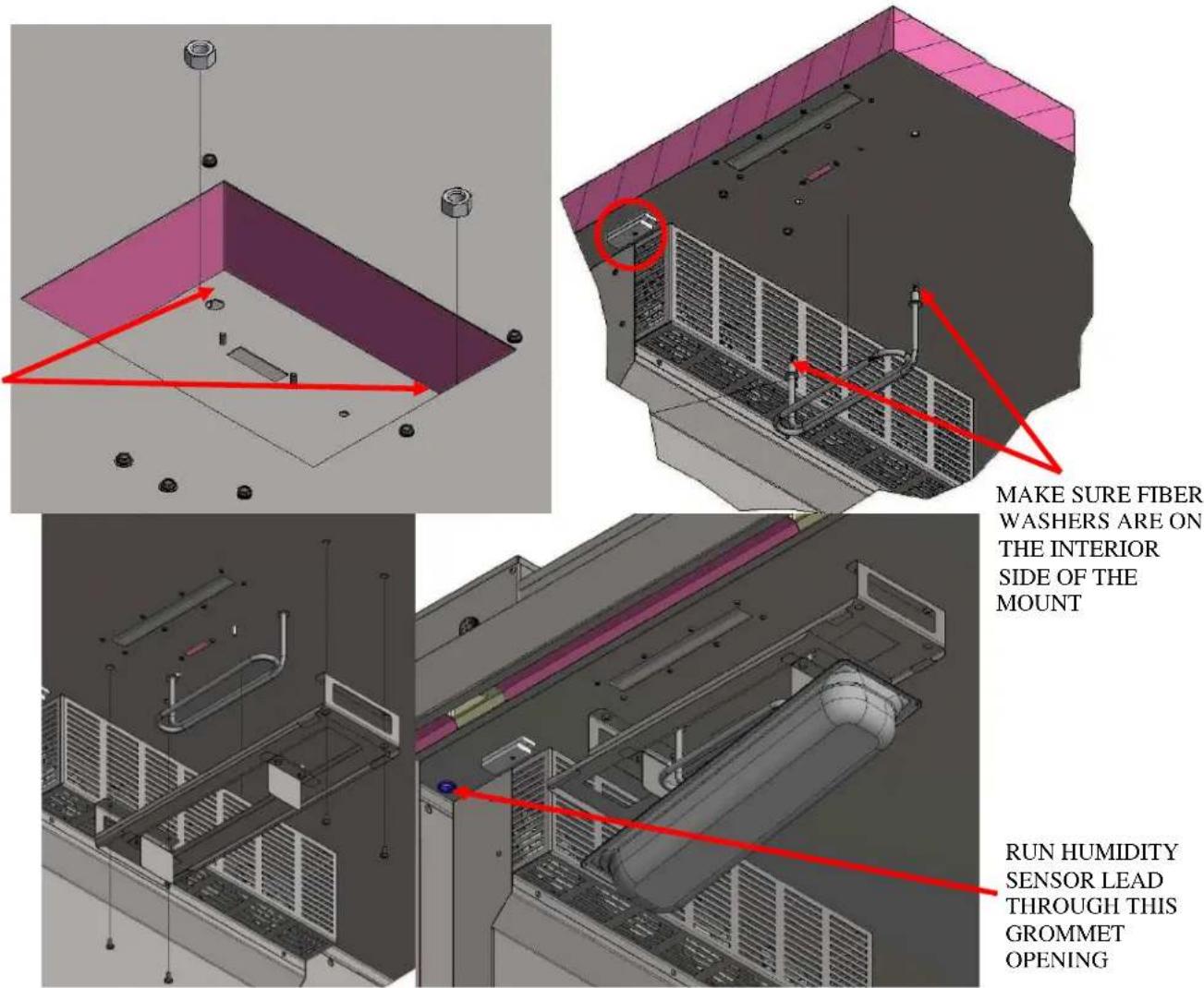
- INSTALL WATER HEATER ELEMENTS (18612-0367) USING THE NUTS SUPPLIED WITH THE ELEMENTS.
○ MAKE SURE GASKET IS IN THE INTERIOR SIDE OF THE MOUNT - INSTALL TWO WATER PAN MOUNTS (50039148) USING (4) 1/4-20 SS PAN HEAD SCREWS (53-0840) EACH
NOTE: USE LONG PHILILPS SCREW DRIVER TO ACCESS ALL FOUR MOUNT HOLES - INSTALL HUMIDITY SENSOR (66-1146) (CIRCLED IN RED), FEED WIRE THROUGH GROMET
- ROUTE HUMIDITY SENSOR LEAD AND ATTACH THE LEAD PORT LABELED "TH SENSOR", AS SHOWN
• SLIDE PANS SLIDE OUT ON PAN MOUNTS AND INSTALL PANS (50039148). - WHEN PANS ARE IN POSITION, MOVE SLIDES BACK

• INSTALL DOOR STRYKERS AS SHOWN WITH TWO 10-32 PHILIPS
o SINGLE DOOR UNITS GET ONE STRYKER
- TWO DOOR UNITS GET TWO STRYKER
• INSTALL DOOR GASKET AS SHOWN.
NOTE: MAKE SURE GASKET IS FULLY SEATED WHEN DONE
- INSTALL DOOR(S) WITH HINGES INSTALLED, AS SHOWN USING (8) 1/4-20 PAN HEAD SCREWS(53-0840) PER DOOR
- USE HINGES SHIMS (KDP_0201) AS NEEDED TO PREVENT DOOR SAG
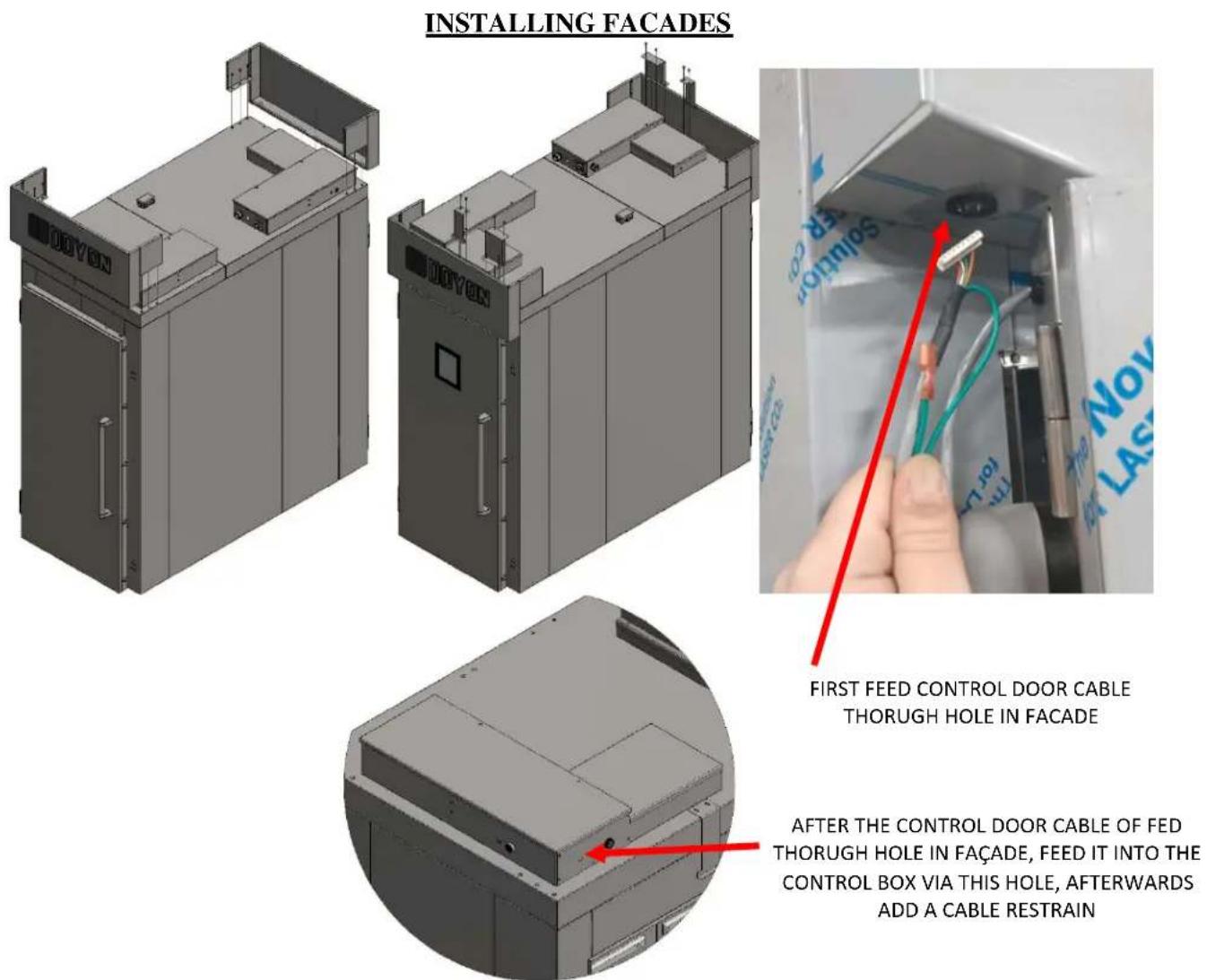
- ATTACH FAÇADE(S) AS SHOWN WITH (6) ¼-20 FLANGE SCREWS (53-0840) PER FACADE
- INSTALL FACADE SUPPORTS (KDP_0048) AND DOOR SWITCH BRACKET (KDP_0049) WITH 10-32 SCREWS AND 1/4 -20 SCREWS (2 EACH BRACKET)
NOTE 1: FACADE SUPPORT (KDP_0048) INTERLOCKS WITH FAÇADE
- CONNECT DOOR SENSOR (REFER TO SUPLLIED ELECTRICAL DRAWING)
NOTE 2: DOOR SWITCH BRACKET(KDP_0049) MUST BE INSTALL ON SAME SIDE AS DOOR HANDLE
- ATTACH DOOR SENSOR WIRES TO THE LEADS IN THE ELECTRICAL BOX
- RUN PIGTAIL ATTACHED TO THE CONTROL DOOR THOUGH THE OPENING ON THE FACADE AND ROUTE IT INTO THE CONTROL BOX
- WHEN ROUTED, PLUG THE CABLE TO PORT LABELED "TO DISPLAY" ON THE CONTROL BOARD
- PLUG GREEN TERMINAL TO THE PORT LABELED "GND" ON THE CONTROL BOARD
o ATTACH CABLE RESTRAIN TO THE CABLE AND BOX WHEN DONE
FINAL INSPECTION
- VERIFY ALL CONNECTIONS ARE CORRECT BY REFERRING TO THE SUPPLIED ELECTRICAL DIAGRAM
• SILICONE OPENINGS WITH WIRE LEADS GOING THROUGH
• REINSTALL COVERS ON ELECTRICAL BOXES - REMOVE ALL PLASTIC FILM FROM THE INTERIOR AND EXTERIOR OF THE UNIT.
- AFTER ALL CONNECTIONS ARE VERIFIED, HOOK UP MAIN POWER TO ELECTRICAL ENTRANCE
• WAIT 8 HRS TO LET SILICONE FULLY CURE BEFORE POWERING UP UNIT
INITIAL START UP
To turn unit on, push the black push button on the electrical box. The box is located on the top of the unit towards the front left corner. Once this button is pushed, there will be no need to use it again during normal operation.

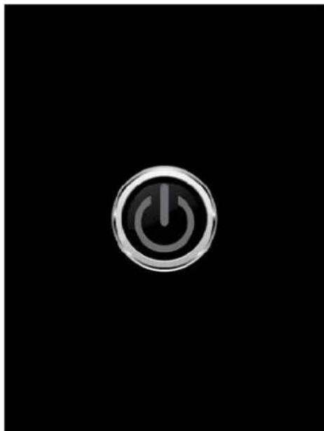
SPLASH SCREEN
This screen is displayed when the unit powers on.
STANDBY SCREEN
This screen is displayed when the unit is in Standby mode. When in standby mode, the unit is powered but is neither proofing nor retarding. Pushing the power icon will activate last used mode.

Temperature Control (Heating) Tapping on this icon will let you enter the desired proofing temperature. Retarding mode Tapping this icon will make the unit go into Retarding mode
Temperature Display Displays set temperature in white font. When you tap on the display it will show you the actual temperature inside of the unit in yellow/orange font.
Humidity Level Display Displays set humidity level in white font. When you tap on the display it will show you the actual humidity level inside of the unit in yellow/orange font.
Humidity Control Tapping on this icon will let you enter the desired humidity level
Tapping this icon will bring up the command screen. When in the command screen, enter
"7123" then press the icon to bring up the setup page for the automatic proofing and retarding mode.
Tapping this icon will turn on automatic proofing and retarding. When the icon is green the automatic control is on. When the icon is green the automatic control is off.
Timer
Pushing the +5 button will add 5 minutes to the
displayed time. Pushing the button will start the timer. When the timer is running, pushing the
button will rest the timer to 5 mins

RETARDING MODE
![graph TD A["40F"] --> B["Proofing Mode"] B --> C["Tapping this icon will make the unit go into Proofing mode"] C --> D["Temperature Display"] D --> E["Displays set temperature in white font. When you tap on the display it will show you the actual temperature inside of the unit in yellow/orange font.…](/content/2026/07/1445047/images/eb15f246df759655b42275e52b97777c76cea3e151e8ee09e3f884f0ceaa45fb.jpg)
Tapping this icon will turn on automatic proofing and retarding. When the icon is green the automatic control is on. When the icon is green the automatic control is off.
AUTOMATIC PROOFING/RETARDING MODE SET UP
This page lets you set up what time your proofer turns on and when it switches to retarder mode
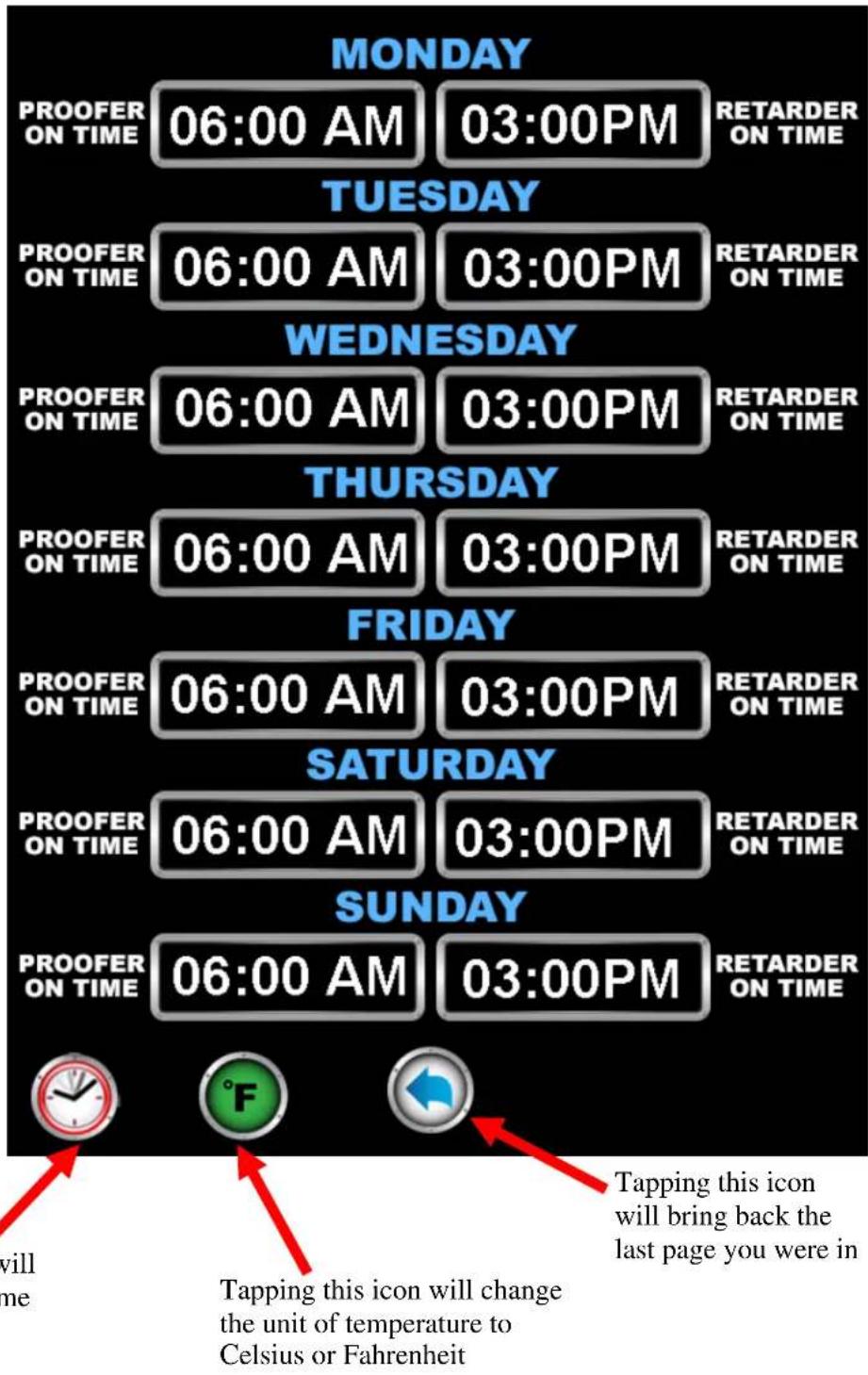
Tapping this icon will bring up the real time clock setup
Tapping this icon will change the unit of temperature to Celsius or Fahrenheit
REAL TIME CLOCK SETUP
This page lets you set up your current time and a day of the week.
REAL TIME CLOCK SETUP

03:00PM

MAINTENANCE AND CLEANING
| Questions | Solutions |
| Clean the inside of the unit with water and soap. | We recommend and sell: Dirt Buster III: Action foam cleaner CHEMCO Part number: NEB201 |
| Clean the unit exterior with a stainless steel cleaner. | We recommend and sell: Stainless steel cleaner SANY or CURTIS (comestible) Part number : NES201 |
| Clean the water system inside of the unit. | Twice a year clean the water pan and the immersion element, Is very important to use a high quality water filter on water system to prevent water line obstruction and scale problem in the water tank. |
LIMITED WARRANTY
(Continental United States Of America And Canada Only)
Doyon Equipment Inc. guarantees to the original purchaser only that its product are free of defects in material and workmanship, under normal use.
This warranty does not cover any light bulbs, thermostat calibration or defects due to or resulting from handling, abuse, misuse, nor shall it extend to any unit from which the serial number has been removed or altered, or modifications made by unauthorised service personnel or damage by flood, fire or other acts of God. Nor will this warranty apply as regards to the immersion element damaged by hard water.
The extent of the manufacturer's obligation under this warranty shall be limited to the replacement or repair of defective parts within the warranty period. The decision of the acceptance of the warranty will be made by Doyon Equipment service department, which decision will be final.
The purchaser is responsible for having the equipment properly installed, operated under normal conditions with proper supervision and to perform periodic preventive maintenance.
If any parts are proven defective during the period of one year from date of purchase, Doyon Equipment Inc. hereby guarantees to replace, without charge, F.O.B. Linière, Quebec, Canada, such part or parts.
Doyon Equipment Inc will pay the reasonable labour charges in connection with the replacement parts occurring within one year from purchase date. Travel over 50 miles, holiday or overtime charges are not covered. After one year from purchase date, all labour and transportation charges in connection with replacement parts will be the purchaser's responsibility.
Doyon Equipment Inc. does hereby exclude and shall not be liable to purchaser for any consequential or incidental damages including, but not limited to, damages to property, damages for loss of use, loss of time, loss of profits or income, resulting from any breach or warranty.
In no case, shall this warranty apply outside Canada and continental United States unless the purchaser has a written agreement from Doyon Equipment Inc.
GARANTIE LIMITÉE
Menominee, MI, United States 49858
Tel.: 1 (906) 863-4401
Toll Free: 1 (800) 338-9886
Internet: http://www.doyon.qc.ca
E-mail: service@nu-vu.com

- TABLE OF CONTENTS
- INTRODUCTION
- THE MANUFACTURER SUGGESTS TO READ THIS MANUAL CAREFULLY
- ATTENTION
- CONSTRUCTION
- SHIPPING
- IMPORTANT-RECEPTION OF THE MERCHANDISE
- INSTALLATION
- IMPORTANT INSTALLATION AND SERVICE
- FOR YOUR SAFETY
- INSTALLERS
- TO THE ELECTRICIAN
- TO THE PLUMBER
- DISTANCES TO RESPECT
- ASSEMBLY
- FOREWORD
- TOOLS REQUIRED
- KDP SERIES CONFIGURATION DIAGRAMS
- WALL PANEL CONFIGURATIONS
- TOP PANEL CONFIGURATIONS
- REFRIGERATION MODULE PLACEMENT
- INSTALLING REFRIGERATION MODULES (RETARDER MODELS)
- FINAL INSPECTION
- INITIAL START UP
- SPLASH SCREEN
- STANDBY SCREEN
- TIMER
- RETARDING MODE
- AUTOMATIC PROOFING/RETARDING MODE SET UP
- REAL TIME CLOCK SETUP
- MAINTENANCE AND CLEANING
- LIMITED WARRANTY
- (CONTINENTAL UNITED STATES OF AMERICA AND CANADA ONLY)
- GARANTIE LIMITÉE
Brand : Doyon
Model : KDPR11
Category : Industrial oven