
E30 - Floor Cleaner Minuteman - Free user manual and instructions
Find the device manual for free E30 Minuteman in PDF.


| Product Type | Automatic Floor Scrubber |
| Brand | Minuteman |
| Model | E30 |
| Dimensions (L x W x H) | 45 x 20 x 35 inches (114 x 51 x 89 cm) |
| Weight | 350 lbs (159 kg) |
| Power Source | 24V DC Battery (2 x 12V deep cycle) |
| Battery Capacity | 180 Ah (typical) |
| Solution Tank Capacity | 20 gallons (76 liters) |
| Recovery Tank Capacity | 18 gallons (68 liters) |
| Cleaning Width | 30 inches (76 cm) |
| Brush Speed | 150-300 rpm (adjustable) |
| Brush Pressure | Up to 80 lbs (36 kg) |
| Vacuum Motor Power | 0.5 HP (373 W) |
| Drive Type | Self-propelled (traction drive) |
| Speed Range | 0-2.5 mph (0-4 km/h) |
| Water Filtration | Float shut-off valve in recovery tank |
| Squeegee Width | 36 inches (91 cm) |
| Maintenance Interval | Daily: empty tanks, clean squeegee; Weekly: inspect brushes, check battery water |
| Safety Features | Emergency stop button, key switch, battery disconnect |
| Spare Parts Availability | Brushes, squeegees, filters, batteries available from authorized dealers |
| Repairability | Modular design; major components (motors, pumps) replaceable |
| Warranty | 1 year standard (check dealer for details) |
| User Manual | Free downloadable PDF at notice-facile.com (42 pages) |
Frequently Asked Questions - E30 Minuteman
User questions about E30 Minuteman
0 question about this device. Answer the ones you know or ask your own.
Ask a new question about this device
Download the instructions for your Floor Cleaner in PDF format for free! Find your manual E30 - Minuteman and take your electronic device back in hand. On this page are published all the documents necessary for the use of your device. E30 by Minuteman.
USER MANUAL E30 Minuteman
E28/E30/E33 (7062.12/.15/.18)
Introduction
Preface
Dear customer, It is our desire that the good characteristics of the E 28/E30/E33 should justify the confidence you demonstrated by making this purchase. Prior to the first use, carefully read the chapter "Safety Information" as this will ensure your safe operation of the machine.
Your own safety, as well as the safety of others, depends to a great extent on how the machine is moved and operated. Therefore, this operation and maintenance manual must be read and understood prior to the machine being used for the first time.
The manual provides valuable information about operation, service and maintenance. The warning symbols as used in this manual identifies items relevant to safety. Please observe the safety provisions (see chapter "Safety Information").
Your authorized Minuteman dealer will be pleased to answer further questions regarding the vehicle or the operation and maintenance manual.
Please be advised explicitly that we cannot accept any legal issues out of the contents of this manual. If repair work has to be performed make sure that only genuine spare parts are used; only genuine spare parts may guarantee a dependable machine. We reserve the right for technical improvement..
Valid as of: July 2007
Minuteman International Inc. 14N845 U.S. ROUTE 20 PINGREE GROVE, IL 60140-8893 U.S.A.
Proper use
The machine is a vacuum scrubbing machine for wet cleaning of hard-surfaced floors. Using the machine beyond this scope of application will be deemed improper use; The manufacturer cannot be held liable for consequential damages; the user alone bears the risk.
The term of proper use also includes operation, maintenance and repair work to be performed in compliance with the manufacturer's specifications.
The E 28/E30/E33 may only be used by persons that are familiar with the machine and aware of possible hazards involved.
If modifications to the machine are made in absence of the manufacturer's prior consent, the latter cannot be held liable for damage resulting from such unauthorized modification.
Introduction
Notes on warranty
The terms of the sales contract apply. Damages are not subject to warranty if they are due to non-compliance with the maintenance and service provisions. The maintenance work has to be performed by an authorized Minuteman service center and confirmed in the "Maintenance certificate" which is the warranty document.
The following is excluded from warranty: fuses, natural wear, damages caused by overload, inexpert handling and unauthorized modification of the machine. Moreover, any claim for warranty cannot be accepted if damages of the machine are caused by fitting parts or accessories without Minuteman's prior and explicit consent or by non-compliance with the maintenance instructions.
Acceptance of the machine
Upon arrival, check machine for possible damages in transit. Follow unpacking instructions on shipping pallet. Each unit has been tested and thoroughly inspected before shipment. Any damage is the responsibility of the delivery carrier who should be notified immediately.
Minuteman International Inc. 14N845 U.S. ROUTE 20 PINGREE GROVE, IL 60140-8893 U.S.A.
Table of Content
Introduction 2
Preface....2
Proper use 2
Notes of warranty ..... 3
Acceptance of the machine .. 3
1 Safety information ..... 5
1.1 Safety and Warning Symbols. 5
1.2 General Provisions....6
1.3 Provisions for Operation.....6
1.4 Maintenance instructions .... 7
1.5 Specific Hazards 8
1.6 Information for Protection of Environment 8
1.7 Labels at the Machine ..... 9
2 First Operation ..... 10
2.1 Instruction..... 10
2.2 Initial charging procedure...10
2.3 Before Taking into Operation 10
2.4 Start Machine ..... 10
2.5 Operation ..... 11
2.6 Stop Machine ..... 11
2.7 After Work 11
2.8 Transporting Machine ..... 11
3 Operation 12
3.1 Method of operation ..... 12
3.1.1 Brush Deck....12
3.1.2 Solution Tank ..... 12
3.1.3 Squeegee....13
3.1.4 Recovery Tank 13
3.1.5 Traction Drive.....13
3.1.6 Batteries and Charger ..... 13
3.1.7 Options.... 13
3.2 Operating and Indicating Elements ..... 14
3.2.1 Operating Panel ..... 14
3.2.2 At the machine ..... 17
4 Technical Data ..... 20
5 Maintenance and Care .... 22
5.1 System Maintenance ..... 22
5.2 Maintenance document .... 23
5.3 Maintenance Schedule.....23
5.4 Battery Systems ..... 28
5.4.1 Charge Batteries ..... 29
5.4.2 Low Discharge Signal sender (LDS) 29
5.4.3 Maintenance of Drive Batteries 29
5.4.4 Remove Batteries.....29
5.4.5 Install Batteries.....29
5.4.6 Disposal of Batteries ..... 29
5.5 Solution Tank 30
5.5.1 Fill Solution Tank ..... 31
5.5.2 Empty Solution Tank ..... 31
5.5.3 Clean Solution Filter..... 31
5.6 Recovery Tank.... 32
5.6.1 Empty Recovery Tank ..... 33
5.6.2 Clean Recovery Tank.....33
5.6.3 Clean Suction Filter ..... 33
5.7 Disc brush Deck.... 34
5.7.1 Clean Brushes ..... 34
5.7.2 Change Brushes 34
5.7.3 Change Roller Bumper..... 34
5.7.4 Change Sealing Strip ..... 34
5.8 Cylindrical brush deck ..... 35
5.8.1 Clean dirt hopper ..... 35
5.8.2 Remove brushes ..... 35
5.8.3 Clean brushes 35
5.8.4 Fit brushes 35
5.8.5 Change roller bumper ..... 35
5.9 Squeegee....36
5.9.1 Clean Squeegee 36
5.9.2 Change Squeegee Blades . . 36
5.9.3 Adjust Squeegee Blades . . . 37
Minuteman Limited Warranty 40
Safety information
1 Safety information
1.1 Safety and Warning Symbols
All paragraphs in this manual referring to your personal safety, the safety of your machine and the environment protection are attributed one of the following warning symbols:
| Safety Symbols Description | |
WARNING Indicates a haz  situation which could result in death or serious injury. situation which could result in death or serious injury. | |
| NOTICE NOTICE | Indicates a potentially hazardous situation which may result in equipment or property damage. |
| Additional Symbols Description | |
Ecological hazard  | Indicates the use of substances representing an inherent danger to the health of the environment |
| Note Indicates important or Additional information. |
Safety information
1.2 General Provisions
- Apart from the provisions contained in this instruction manual, the general safety provisions and the accident prevention regulations as imposed by law have to be complied with.
- Before taking your machine into operation, carefully read the instruction manual as well as other separate instructions for accessories or attached implements and comply with all points mentioned there during work.
- Persons being trained by qualified Minuteman technicians only are authorized to operate, service and repair the machine.
- You are advised to thoroughly study the safety instructions since precise knowledge helps prevent errors during machine operation and thus guarantee proper use of the machine.
- The operating instructions have to be at hand at the place of use of the machine, and therefore have to be kept readily available at the machine.
- When selling or letting the machine for rent, hand out these documents
to the new owner/operator and have the transfer certified!
- The warning and instruction plates attached to the machine contain valuable advice about safe operation. Immediately replace incomplete or illegible labels.
- As far as safety standards are concerned, use only genuine spare parts!
1.3 Provisions for Operation
- Before first operation of the machine, fully charge the battery with an initial charging procedure and comply with the operating instructions of the charger as well as with those of the battery manufacturer. Minuteman cannot be held liable for damages resulting from an insufficient initial charge.
- Before taking into operation, check the machine for operational safety! Immediately repair any malfunctions!
-
It is indispensable for the operator to get acquainted with all attached implements and controls as well as with their function before operation begins. Once you have started to work, no time will be left to do so!
-
When working with the machine use firm and skid proof shoes.
- The machine may be used only on such surfaces clearly specified by the owner or his authorized representative.
- When working with the machine, pay strict attention to any persons in the close vicinity.
- Start moving immediately after brush deck has switch on otherwise the brush might leave traces on the floor. Lift the brush head before moving over obstacles (doorsteps).
- Only fold open empty recovery tank.
- Use only cleaning agents suitable for automatic machines (low-foaming) and comply with the instructions for use, disposal and with the warning information specified by the cleaning agent's manufacturer.
- The machine is not designed for collecting hazardous, flammable or explosive dusts or substances.
- Usage of the machine in explosive areas is prohibited.
- Remove the key to avoid unauthorized use of the machine.
- Before transporting the machine, lift the squeegee and the brush deck.
Safety information
Adapt driving habits to local conditions.
- The machine may be used only for operation on flat floors with a maximum inclination of up to 2%.
1.4 Maintenance instructions
- The daily and weekly maintenance and repair task must be performed by a qualified operator. For further maintenance and repair work please contact your local Minuteman service center.
- Observe the maintenance activities and intervals set out in the instruction manual.
- Maintenance and repair work may be carried out only by means of appropriate tools.
- Have the machine checked for safe condition by an expert at regular intervals (recommendation: at least once yearly) as well as after modifications or repair.
- Spare parts have to equal the technical requirements as specified by the manufacturer! Genuine spare parts guarantee compliance with these requirements.
- Switch off the engine and remove
the key before inspecting the machine or performing any maintenance work.
- To prevent the machine from being used by unauthorized persons, the control key must be removed.
- When performing work at the electrical system, be sure to disconnect the battery plug.
- Make sure to protect the recovery tank against accidental closing or tilting down before working in the area of a lifted tank lid.
- Do not clean the electrical parts by means of high-pressure cleaning equipment.
- The use of aggressive detergents is prohibited.
- Let the machine dry after cleaning. Do not stroe the machine with liquid remaining in the tanks
- All protective devices must be in place before operating the machine.
1.5 Specific Hazards
Electric system
- Only use genuine fuses with specified ratings.
- In case of malfunction of the electric system, shut the machine down im-
mediately and have it serviced.
- Only qualified personnel are authorised to work on the electrical system and only according to electro-technical rules.
- Inspect/check the electrical equipment of the machine at regular intervals.Clear up any defects immediately, such as loose connections or damaged cables..
Battery
- Observe the operating instructions of the battery manufacturer.
- Never place metal objects or tools on batteries - short-circuit hazard!
- Due to alteration of the center of gravity, only use batteries as released and at the prescribed position only.
- Charge batteries only in areas with sufficient ventilation. – Explosion hazard!
Safety information
1.6 Information for Protection of Environment
- For safe use of substances inheriting a danger to health and environment specific knowledge is required.
- Observe the legal directives and local regulations for disposal of detergents.
• Used batteries labelled as recyclable contain reusable economic goods. According to the crossed dustbin label these batteries must not be added to the normal waste.
Safety information
1.7 Labels at the Machine
The following safety and information labels are legibly attached to the machine. Replace missing or illegible labels immediately.
Minuteman nameplate (Fig. 1/1)
Minuteman®
Machine identification number (Fig. 1/2)

Recovery tank drain hose (Fig. 1/3)
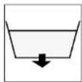
A = Read and observe the instruction manual
B = Maximum inclination of 2%
C = Do not clean the machine by means of high-pressure cleaning equipment

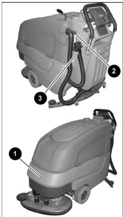
Fig.1
First Operation
2 First Operation
2.1 Instruction
Only persons trained by qualified Minuteman technicians are authorized to operate, service and repair the machine. Operators must read and understand this manual before operating or maintaining this machine.
2.2 Initial charging procedure
NOTICE
Before first operation of the machine, fully charge the battery with an initial charging procedure and comply with the operating instructions of the charger as well as with those of the battery manufacturer. Minuteman cannot be held liable for damages resulting from an insufficient initial charge.
2.3 Before Putting into Operation
Complete the following inspections before taking the machine into operation:
- Check the area around the machine for signs of leakage. Hoses, lines and tanks must be free from any leakage or damage.
- Install brushes and squeegee, see
maintenance chapter.
- Install batteries and connect battery plug, see maintenance chapter.
- Check battery charge and recharge if required. An initial charge is required before first operation of the machine.
- Empty recovery tank and clean it if required, see maintenance chapter.
- Refill solution tank and add cleaning agent according to the manufacturer's recommendations.
NOTICE
Use only cleaning agents suitable for automatic machines (low-foaming) and comply with the instructions for use, disposal and with the warning information specified by the cleaning agent's manufacturer.
2.4 Start Machine
Proceed with the following to set the machine to operating mode:
- Disconnect mains plug of the charger from outlet and fasten to holder.
- Switch on machine by actuation of key switch from position (0) to position (1).
First Operation
2.5 Operation
- Switch on the machine.
- Use lever (Fig5/4) to lower squee-gee. Vacuum motor switches on automatically.
- Use solution control (Fig5/3) to set the desired flow rate.
- Use pedal (Fig5/1) to lower brush deck. The solution supply switches on automatically.
- Use speed control knob (Fig.4/9b) to adjust work speed. Use the direction switch (Fig.4/9a) to select forward or reverse. Pull the bail handle (Fig.4/9c) to start moving.
NOTICE Start moving machine immediately after switching on the brush deck, otherwise the brushes leave traces on the floor. Lift brush deck before passing over steps and other obstacles.
2.6 Stop Machine
When the bail handle is released it automatically returns to the neutral position. The machine stops. Secure the machine against unintentional movements or against being started.
2.7 After Work
- Move machine to a suitable site for maintenance.
- Stop machine, lift squeegee and brush deck and remove the key.
- Empty and clean recovery tank.

Observe the legal directives and local regulations for disposal of detergents.
- Check solution filter.
- Check seals and suction hose.
- Check operating fluid levels, function and setting.
- Charge batteries.
- Clean the machine.
Empty the solution tank before shutting down the machine for a longer time.
NOTICE Do not clean the electrical parts by means of high-pressure cleaning equipment.
2.8 Transporting the machine
To transport the machine to the work area, switch it on, lift-out squeegee and brush deck, pull the bail handle start movement.
2.9 Tie-down points
When transporting on a vehicle or trailer, the machine has to be secured. Tie the machine down firmly by using the front eye bolts (Fig. 2/1) and the rear chassis (Fig. 2/2) as tie-down points.


Fig.2
Operation
3 Operation
3.1 Method of Operation General
The E 28/E30/E33 is a vacuum scrubbing machine for wet cleaning of hard-surfaced floors.
3.1.1 Brush Deck
Lower brush deck (Fig. 3/1) via pedal before scrubbing. The brushes rotate and solution supply switches on automatically. When the machine stops, brushes and solution supply switch off automatically.
3.1.2 Solution Tank
Fill the solution tank (Fig. 3/2) after removing the cover. The solution tank holds 23.8 gallons and the filling level can be checked visually (through transparent hose). Regulation of solution amount is available via adjustment handle.

Fig.3
Operation
3.1.3 Squeegee
The movable squeegee (Fig. 3/3) consists of the squeegee lift mechanism, the vacuum motor and squeegee blades. The soiled water is wiped from the floor by means of squeegee blades. Squeegee is lowered via hand lever. Simultaneously, the vacuum switches on. The vacuum motor works independent of direction of travel and even if the machine stops. Second actuation of the hand lever lifts the squeegee up again and vacuum motor is automatically switched off with a delay of 15 seconds.
3.1.4 Recovery Tank
The soiled water is taken from squee-gee to the recovery tank (Fig. 3/4) by vacuum motor and suction hose.
3.1.5 Traction Drive
The machine features a continuous traction drive (Fig. 3/6). The electronic traction drive control realises modification of travel speed, direction as well as dynamic braking.
3.1.6 Batteries and Charger
The machine is equipped with 235 Ah batteries (Fig. 3/5), an automatic charger unit (Fig. 3/7) and a low discharge signal sender (LDS) for protection against low discharge.
3.1.7 Options
- Extraction hose including suction pipe, joint nozzle and wet suction nozzle
- Mop holder and tool-box for cleaning utensils

Accessories such as brushes, rollers, pads, pad holder with centerlock and sealing strips are available. Contact your Minuteman Dealer for more information.
Operation
3.2 Operating and Indicating Elements
3.2.1 Operating Panel
1 Display
2 Keys switch
3 Battery charge indication
4 LDS indicator
5 Symbol brush drive
6 Symbol vacuum drive
7 Hourmeter
8 Symbol Service indicator
9 free
10 Symbol Silence Kit (optional)
11 Symbol solution flow
12 Tip-switch Silence Kit (optional)
13 Tip-switch solution dosage
14 Tip-switch solution supply On/Off
15 Symbol vacuum scrubbing tool (optional)
16 Drive direction control (16a) with speed control knob (16b) and bail handle (16c)
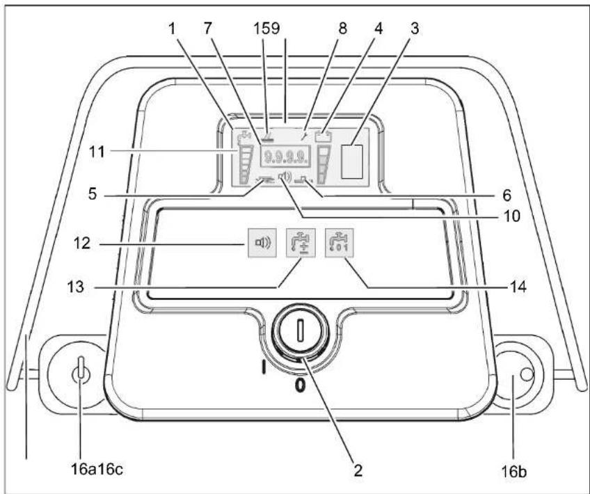
Fig.4
Operation
Display (Fig. 4/1)
This panel allows centralized monitoring of functions and detection of all available operating modes.

The key switch turns the electrical system on and off.

Remove the key to avoid un- authorized use of the machine.

Battery charge indication (Fig. 4/3)
Battery charge indication appears on the panel during the charging procedure and shows the current charge condition of batteries during the procedure.
The following symbols appear: Battery symbol A < charge of 20 % Battery symbol B = charge of 80 % Battery symbol C = charge of 100 % Battery symbol D (flashes) = error

LDS indicator (Fig. 4/4)
Upon switching on, the LDS indication is output on the panel to show the current battery charge condition during operation. Additional Information see chapter maintenance.

Symbol brush drive (Fig. 4/5)
This symbol appears when brush drive is switched on.

Symbol vacuum motor (Fig. 4/6)
This symbol appears when vacuum motor drive is switched on.

Upon switching on, the hourmeter briefly displays the software version and the last error code. Then the current operating hour level is shown.

Service indicator (Fig. 4/8)
The service indicator lights after occurrence of a system error and cleaning or transporting procedure is interrupted. In addition to the service indicator, a 4-digit code is displayed on the hourmeter.
Operation

free (Fig. 4/9)

Silence Kit tip symbol (optional) (Fig. 4/10)
This symbol appears when Silence Kit tip-switch is switched on.
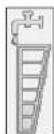
Solution flow symbol (Fig. 4/11)
This symbol appears upon actuation of the solution flow tip-switch.

Silence Kit tip-switch (optional) (Fig. 4/12)
This tip-switch is used to change vacuum motor to silent mode. The silent mode symbol appears in the display.

Solution flow tip-switch (Fig. 4/13)
This tip-switch is used to regulate the amount of solution. Additionally, solution amount is adapted to driving speed. The display shows a six-stage symbol for the supplied amount of solution.

Solution supply ON/OFF tip-switch (Fig. 4/14)
This tip-switch is used to switch solution supply ON or OFF.

Scrubbing tool symbol (optional) (Fig. 4/15)
This symbol appears when scrubbing tool-switch (A) is switched on

Hand cleaning tool (optional)
Hand-cleaning tool with spray function for the E 24 with scrubbing tool connection for thorough cleaning on areas which are difficult to reach.
Drive direction control with speed control knob/bail handle (Fig. 4/16)
The drive direction control (16a) is used to control the driving direction (forward or reverse). The bail handle (16c) must be pressed in order to drive. The speed can be adjusted continuously by means of the speed control knob (16b). The machine stops when the bail handle is released (deadman function).

Protect the machine against rolling off before leaving it un-attended.
Operation
3.2.2 At the machine
1 Brush deck pedal
2 Opening of solution tank
3 Squeegee lever
4 Solution filter
5 Recovery drain hose
6 Solution level indication
7 Brush ejector
8 Power connection charger unit

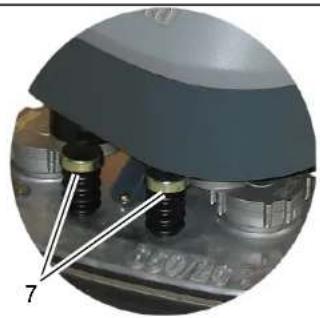


Fig.5
Operation
Brush deck pedal(Fig. 5/1)
Use this pedal to lift and lower the brush deck.
Opening of solution tank (Fig. 5/2)
The solution tank is filled after folding up the opening.
Squeegee lever (Fig. 5/3)
Use this hand lever to lift and lower the squeegee.
Solution filter (Fig. 5/4)
While solution flows from tank to brush deck, it is cleaned by the filter element.
Recovery tank drain hose (Fig. 5/5)
This hose allows draining the collected soiled water from the tank.
Solution tank drain hose (Fig. 5/6)
This hose allows draining the solution tank.
Brush ejector (Fig. 5/7)
The brush ejector makes brush removal fast and easy.
Power connection charger unit (Fig. 5/8)
The power connection supplies the charger unit with power.
Operation
Dirt hopper guiding rail (Fig. 6/1)
The dirt hopper located at the cylindrical brush deck is fastened by a guiding rail. This dirt hopper may be easily removed for cleaning.
Lever for cylindrical brush seating (Fig. 6/2)
This lever (both sides) is used to release/lock the cylindrical brush seating. The cylindrical brushes may be easily removed without tools.
Swing aside squeegee
Swing the squeegee aside in lifted position to allow passage through narrow clearances. This can be done by foot or by hand by swinging the squeegee to the left in the area of the deflector bail / roller bumper until the locking pin (Fig. 6/3) catches. In order to release locking of the squeegee, actuate the hand lever (Fig. 5/3) of the squeegee lift mechanism (lowering).

Fig.6 1 Dirt hopper guiding rail
2 Lever for cylindrical brush seating
3 locking pin
Technical Data
4 Technical Data
| Disc brush deck Cylindrical brush deck | ||||||||
| Machine length | 68.0 in 173 cm 65.0 in 165 cm | |||||||
| Machine height 43.7 in 111 cm 43.7 in 111 cm | ||||||||
| Machine width without Squeegee 34.7 in 88 cm 30 in 76 cm | ||||||||
| Machine width with Squeegee 43.3 in 110 cm 43.3 in 110 cm | ||||||||
| Working width 33.5 in 85 cm 27.6 in 70 cm | ||||||||
| Squeegee width 43.3 in 110 cm 43.3 in 110 cm | ||||||||
| Surface performance theoretical | 36600 ft 2 /h | 3400 m 2 /h | 30140 ft 2 /h | 2800 m 2 /h | ||||
| Service voltage | 24 V | 24 V | 24 V | 24 V | ||||
| Nominal power drive motor | 260 W | 260 W | 260 W | 260 W | ||||
| Nominal power vacuum motor | 520 W | 520 W | 520 W | 520 W | ||||
| Nominal power brush motor | 2x720 W | 2x720 W | 2x720 W | 2x720 W | ||||
| Number of brushes | 2 Qty. | 2 Qty. | 2 Qty. | 2 Qty. | ||||
| Diameter of brushes | 17 in 43 cm 5.9 | in 15 cm | ||||||
| Working speed | 3.1 mph | 5,0 km/h | 3.1 mph | 5,0 km/h | ||||
| Solution tank | 23.8 gal 90 l | 23.8 gal 90 l | ||||||
| Recovery tank | 21.7 gal 82 l | 21.7 gal 82 l | ||||||
| Weight without batteries and solution | 496 lb | 225 kg | 441 lb | 200 kg | ||||
| Weight with solution and batteries | 1155 lb | 524 kg | 1100 lb | 499 kg | ||||
Technical Data
| Noise emissionThe sound pressure level measured under maximum conditions of use (LwA) according to DIN EN 60335-2-72 amounts to: dB (A) 82The sound pressure level measured (at the ear of the driver) under normal conditions of use (LpA) according to DIN EN 60335-2-72 amounts to:Measurement inaccuracy (KpA): dB (A) 1,6 | dB (A) | 67 |
| VibrationThe frequency weighted acceleration measured according to DIN EN ISO 5349 which have an effect upon the upper limbs (hand-arm-system) amounts under normal working conditions: | m/s2 < 2,5 |
Maintenance and Care
5 Maintenance and Care General

Before proceeding to maintenance and care work you are advised to read and comply with the Safety Information chapter!
Compliance with the recommended maintenance work will ensure that you always have a reliable machine available.
Daily or weekly maintenance and repair work may be executed by the driver/operator having been trained accordingly. Further Minuteman system maintenance work must be completed executed by qualified personnel only. Please contact your local Minuteman Service Center or Minuteman contract dealer. We cannot be held liable for damages resulting from non-compliance with these instructions.
Please indicate the machine's serial number with any enquiry or spare part order, see paragraph 1.7 - Nameplate.
5.1 Minuteman System Maintenance
The Minuteman System Maintenance:
• guarantees reliable operability of the Minuteman machines (preventive maintenance)
- minimizes operating costs, repair costs and maintenance costs
- ensures long service life and operability of the machine
The Minuteman System Maintenance is structured in separate modules and determines specific technical works to be executed as well as the intervals for such maintenance works. For any specific maintenance type, the replacement parts are determined and listed in spare part kits.
System Maintenance K:
To be performed by the customer in accordance to the maintenance and care instructions contained in the operating instructions (daily or weekly). The driver/operator will be instructed upon delivery of the machine.
System Maintenance I :
(every 125 hours of operation)
To be performed by qualified personnel of authorized Minuteman Service Centre in accordance with the machine-specific system maintenance including spare part kit.
System Maintenance II:
(every 250 hours of operation)
To be performed by qualified personnel of authorized Minuteman Service Centre in accordance with the machine-specific system maintenance including spare part kit.
System Maintenance S:
(every 500 hours of operation safety check)
To be performed by qualified personnel of authorized Minuteman Service Centre in accordance with the machine-specific system maintenance including spare part kit.
Maintenance and Care
5.2 Maintenance Document
| Handing overUpgradeTest driveHandling over to the customerInstructioncarried out on:at ____ operating hours | System Maintenance I125 operating hoursWorkshop stampcarried out on:at ____ operating hours | System Maintenance II250 operating hoursWorkshop stampcarried out on:at ____ operating hours | System Maintenance I375 operating hoursWorkshop stampcarried out on:at ____ operating hours |
| System Maintenance S500 operating hoursWorkshop stampcarried out on:at ____ operating hours | System Maintenance I625 operating hoursWorkshop stampcarried out on:at ____ operating hours | System Maintenance II750 operating hoursWorkshop stampcarried out on:at ____ operating hours | System Maintenance I875 operating hoursWorkshop stampcarried out on:at ____ operating hours |
| System Maintenance S1000 operating hoursWorkshop stampcarried out on:at ____ operating hours | System Maintenance I1125 operating hoursWorkshop stampcarried out on:at ____ operating hours | System Maintenance II1250 operating hoursWorkshop stampcarried out on:at ____ operating hours | System Maintenance I1375 operating hoursWorkshop stampcarried out on:at ____ operating hours |
Maintenance and Care
5.3 Maintenance Schedule
System Maintenance Customer
The daily and weekly maintenance intervals must be performed by the customer/operator.
| To be performed | Interval | |
| daily weekly | ||
| Fill solution tank and proceed to chemical agent dosage | o | |
| Charge batteries o | ||
| Check brush head and clean if required o | ||
| Check squeegee and clean if required o | ||
| Clean tank lid seal of the recovery tank o | ||
| Empty recovery tank. Clean recovery tank and suction filter o | ||
| Check brushes/pads and replace if required o | ||
| Clean suction hose of recovery tank o | ||
| Check squeegee sealing strips and turn around or replace if required | o | |
| Clean drain hose of solution tank o | ||
| Check solution supply to brushes and clean if required o | ||
| Check solution filter and clean if required o | ||
| Test drive and function test o | ||
Maintenance and Care
System Maintenance I
The following maintenance work must be performed by an authorized Minute-man Service workshop.
| To be performed | Interval |
| every 125 hours of operation | |
| Check battery charger o | |
| Check tank lid seal of the recovery tank and replace if required | o |
| Check drain hose of the recovery tank and replace if required | o |
| Grease joints at the brush lift-out o | |
| Check wheel fixing screws and tighten (24 lb ft) if required | o |
| Check condition of tires o | |
| Grease joints at the squeegee holder o | |
| Test drive and function test o |
Maintenance and Care
System Maintenance II
The following maintenance work must be performed by an authorized Minute-man Service workshop.
| To be performed | Interval |
| every 250 hours of operation | |
| Perform maintenance works according to System Maintenance I | o |
| Inspect steering rollers for tread damages and bearing slackness and replace if required | o |
| Check drain hose of the recovery tank and replace if required | o |
| Check deflector roller of the brush head and replace if required | o |
| Check suction hose for tight fitting and damages and replace if required | o |
| Check supporting wheel of the squeegee and replace if required | o |
| Test drive and function test o |
Maintenance and Care
System Maintenance S (Safety check)
The following maintenance work must be performed by an authorized Minute-man Service workshop at least once a year.
| To be performed | Interval |
| every 500 hours of operation | |
| Perform maintenance works according to System Maintenance II o | |
| Clean travel drive motor from carbon dust and check carbon brushes for smooth operation and wearing and replace carbon brushes if required | o |
| Clean brush motors from carbon dust and check carbon brushes for smooth operation and wearing and replace carbon brushes if required | o |
| Test drive and function test o |
Maintenance and Care
5.4 Battery Systems
1 LDS display
2 Charger indicator
3 Charger
4 Mains cable charger
5 Battery connector
6 Batteries
7 Recovery tank
8 Support
9 Wiring diagram

Handling and changing the batteries may be performed only by maintenance staff.

Fig.7
Maintenance and Care
5.4.1 Charge Batteries
Use the integrated battery charger (Fig. 7/3) to charge batteries. Proceed to connection of the charger by means of the mains cable (Fig. 7/4) with safety plug. Charging batteries is recommended if at least one bar of the LDS display has extinguished after operation of the machine. On this behalf you are requested to observe the operating instructions of the charger 88-60-2723 as well as the operating instructions of the battery manufacturer. In case it is intended to change the type of battery the charger has to be adjusted only by Minuteman contract workshops.
NOTICE
Charge the batteries properly before starting the machine for the first time. Minuteman cannot be held liable for battery damage resulting from failure to initially charge batteries.

Provide for sufficient ventilation of areas where batteries are charged. – Explosion hazard!
5.4.2 Low Discharge Signal sender (LDS)
The machine has been equipped with a charge indicator to preclude the batteries from low discharge. This low discharge signal sender has been integrated into the electronics. If other batteries are used, readjustment of the low discharge signal sender is required.
NOTICE
Only Minuteman contract workshops are authorized to adjust the low discharge signal sender.
5.4.3 Maintenance of Drive Batteries
Refer to operating instructions 88-60-2556 for information on care of drive batteries.
5.4.4 Remove Batteries
- Park machine on level ground.
- Switch off machine by key switch.
- Open empty recovery tank (Fig. 7/7) and secure by support (Fig. 7/8).
- Disconnect battery connector (Fig. 7/5).
- Disconnect battery connection cables.
- Remove batteries.
5.4.5 Install Batteries

Due to alteration of the center of gravity, only use batteries as released and at the prescribed position only.
- Switch off machine by key switch.
- Open empty recovery tank (Fig. 7/7) and secure by support (Fig. 7/8).
- Place batteries into trough according to figure.
- Connect battery poles and enclosed connecting cables according to wiring diagram (Fig. 7/9). Provide for tight fitting and grease poles.
5.4.6 Disposal of Batteries
Used batteries labelled by the recycling sign contain re-usable substances. Such batteries must not be added to normal household waste. Obtain local information for the proper disposal of used batteries.
Maintenance and Care
5.5 Solution tank
1 Solution tank
2 Marker
3 Fill level hose
4 Solution filter
5 Tank lid

Fig.8
Maintenance and Care
5.5.1 Fill solution tank
Fill solution tank (Fig. 8/1) before work or as required. Park vehicle on level ground. Open tank lid (Fig. 8/5) and fill tank up to the maximum (1/1 marker) (Fig. 8/2).
Alternatively, filling of the machine via quick coupling (Fig. 8/6) is available. Before doing so, connect the filling hose of the dosage unit and the quick coupling. The floater valve automatically closes after the maximum filling level has been attained.
(Refer to specific operating instructions for information on operation of the dosage unit)
The maximum admissible service pressure of the floater unit is 87psi.
5.5.2 Empty solution tank
Park vehicle such that the fill level hose (Fig. 8/3) is located above the drain aperture in the floor. Take fill level hose from holder and remove lid.
5.5.3 Solution Filter
Check solution filter (Fig. 8/4) at weekly intervals and clean or replace if required.
NOTICE Only clean solution filter when the solution tank is empty.
- Empty solution tank (Fig. 8/1), siehe Abschnitt 5.5.2.
- Unscrew filter cap.
- Remove the filter element from the filter case for cleaning. Replace if required.
- Re-install filter element and filter cap.
Maintenance and Care
5.6 Recovery tank
1 Recovery tank
2 Drain hose
3 Suction filter
4 Tank lid

Fig.9
Maintenance and Care
5.6.1 Empty recovery tank
Clean recovery tank (Fig. 9/1) at daily intervals, as required or upon acoustic signal (increased suction turbine speed).
- Take machine to appropriate place for discharge.
- Park machine such that drain hose attains drain aperture in the floor.
- Switch off machine.

Observe the legal provisions and the local regulations for disposal of detergents!
- Take drain hose (Fig. 9/2) from holder and empty recovery tank completely.
5.6.2 Clean recovery tank
Clean recovery tank (Fig. 9/1) at daily intervals or as required.
- Empty recovery tank, siehe Abschnitt 5.6.1.
- Open tank lid (Fig. 9/4) of the recovery tank.
- Take drain hose (Fig. 9/2) from holder and empty recovery tank completely.
- Remove remaining dirt by rinsing with clean water.
- Rinse drain hose as well.
5.6.3 Clean Suction Filter
Check suction filter (Fig. 9/3) for function at daily intervals and clean if required. The suction filter is clipped and can be easily removed.
Maintenance and Care
5.7 Disc brush deck
1 Brush deck pedal
2 Brush deck
3 Brush ejectors
4 Roller bumper
5 Sealing strip
5.7.1 Clean Brushes
Clean brushes of the brush deck (Fig.
10/2) at daily intervals or as required.
- Use pedal (Fig. 10/1) to lift up brush deck.
- Press brush ejectors (Fig. 10/3) down to remove brushes for cleaning.


5.7.2 Change Brushes
Check brushes of the brush deck for wearing at weekly intervals. Replace brushes if bristles are worn down to a length of 5/8".
- Use pedal (Fig. 10/1) to lift up brush deck.
- Press brush ejectors (Fig. 10/3) down to remove old brushes.
- Push new brush under brush deck and use both hands to press it into seating.
5.7.3 Change Roller Bumper
Check roller bumper(Fig. 10/4) at weekly intervals or replace as required.
5.7.4 Change Sealing Strip
Check sealing strip (Fig. 10/5) at weekly intervals or as required. Before doing so, open toggle-type fastener and remove sealing strip. Proceed to mounting in reverse order.
Fig.10
Maintenance and Care
5.8 Cylindrical Brush Deck
1 Brush deck pedalt
2 Dirt hopper
3 Cylindrical brush deck
4 Roller bumpers
5 Quick-release
6 Feed inlet
7 Brush seating
8 Locking lever

Fig.11
5.8.1 Clean dirt hopper
Clean dirt hopper (Fig. 11/2) at daily intervals or as required.
Remove dirt hopper from the right machine side (seen in direction of travel).
Use quick-release (Fig. 11/5) to loosen feed inlet (Fig. 11/6) and clean dirt hopper.
5.8.2 Remove brushes
- Lift up cylindrical brush deck (Fig. 11/3) by pedal (Fig. 11/1).
- Release brush seating (Fig. 11/7) by locking lever (Fig. 11/8).
- Remove brush seating by lowering and removing it to the front.
- Remove and check the brushes.
5.8.3 Clean brushes
Clean brushes in the brush deck at daily intervals or as required.
5.8.4 Fit brushes
Check brushes in the brush deck for wearing at weekly intervals and replace as required.
- Insert brush into brush deck and let it catch (teeth A have to point to the outside).
- Place brush seating and lock by lever.
5.8.5 Change roller bumper
Check roller bumpers (Fig. 11/4) at weekly intervals and replace if required.
Maintenance and Care
5.9 Squeegee
1 Squeegee
2 Star-shaped knob
3 Adjusting screw for angle adjustment
4 Suction hose
5 Fastening device
6 Washers for height adjustment
5.9.1 Cleaning the Squeegee
Check the squeegee (Fig. 12/1) daily and clean as necessary.
To clean it lift up the squeegee, pull off the suction hose (Fig. 12/4), loosen the two star-shaped knobs (Fig. 12/2) and remove the squeegee.
5.9.2 Change the Squeegee Blades
Check the inner and outer squeegee blades on the squeegee (Fig. 12/1) weekly for signs of wear. The squeegee blades can be used fourfold by turning them.
- Lift the squeegee up.
- remove the suction hose, loosen the two star-shaped knobs and remove the squeegee.
- Unlock the fastening device (Fig. 12/5) and remove the outer squeegee blade. Turn the squeegee blade or install a new one. Change the inner squeegee blade in the same way.

Fig.12
Maintenance and Care
5.9.3 Adjusting the Blades Angle Adjustment
The angle adjustment is the decisive factor in ensuring that the squeegee blades on the squeegee lie evenly on the floor.
- Park the machine on a level surface and lower the squeegee.
- Loosen the counternut on the adjusting screw (Fig. 12/3) and adjust the squeegee using the adjusting screw so that the ends of the squeegee blades have contact with the floor. Figure A
Turn the adjusting screw counterclockwise: The clearance between squeegee blade and floor is reduced in the center.
Figure B
Turn the screw clockwise: The clearance between squeegee blade and floor is increased in the center.
- Switch the machine on and check the suction pattern. When the machine is operating, the entire surface of the squeegee blades (center and outer areas) must be applied as evenly as possible.
- Tighten the counternut on the adjusting screw at 5 lb ft.
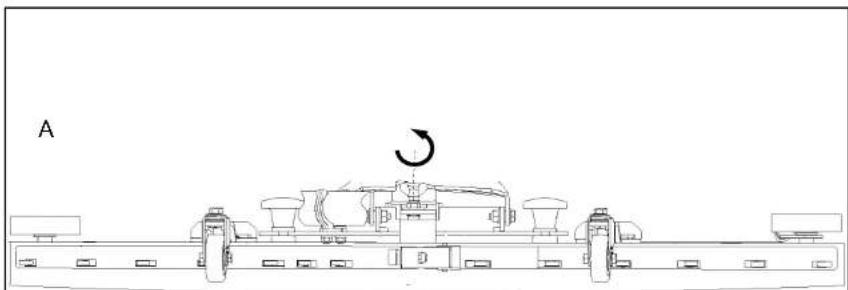

Fig.13
Maintenance and Care
Height Adjustment
The height adjustment is set to 3 mm at the factory. If streaks are produced, despite an optimum angle adjustment, the clearance between the casters and floor must be adjusted by changing the number of washers on the holder.
In cases of very smooth floors, e.g. finished floors, PVC, linoleum, etc. Number of washers = 2. This corresponds to a clearance of approx. 2 mm.
In cases of very uneven floors, e.g. poorly laid tiles (water does not run off) Number of washers = 4. This corresponds to a clearance of approx. 4 mm.

The Squeegee 110 cm (7569) is equipped with two additional rollers which are adjusted at the factory to a distance of 10 mm to the floor by means of spacers.
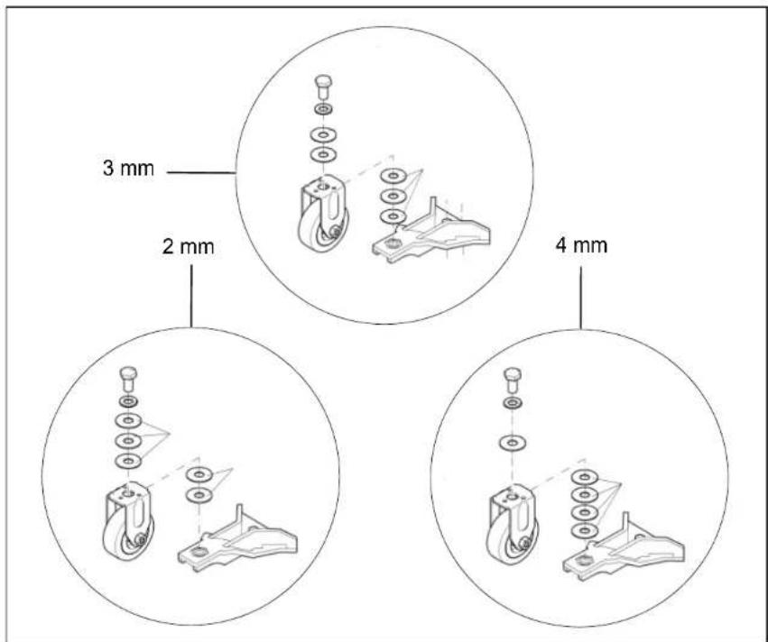
Fig.14
Maintenance and Care
Minuteman International Made Simple Commercial Limited Warranty
Minuteman International, Inc. warrants to the original purchaser/user that the product is free from defects in workmanship and materials under normal use. Minuteman will, at its option, repair or replace without charge, parts that fail under normal use and service when operated and maintained in accordance with the applicable operation and instruction manuals. All warranty claims must be submitted through and approved by factory authorized repair stations.
This warranty does not apply to normal wear, or to items whose life is dependent on their use and care, such as belts, cords, switches, hoses, rubber parts, electrical motor components or adjustments. Parts not manufactured by Minuteman are covered by and subject to the warranties and/or guarantees of their manufacturers. Please contact Minuteman for procedures in warranty claims against these manufacturers.
Special warning to purchaser -- Use of replacement filters and/or prefilters not manufactured by Minuteman or its designated licensees, will void all warranties expressed or implied. A potential health hazard exits without original equipment replacement.
All warranted items become the sole property of Minuteman or its original manufacturer, whichever the case may be.
Minuteman disclaims any implied warranty, including the warranty of merchantability and the warranty of fitness for a particular purpose. Minuteman assumes no responsibility for any special, incidental or consequential damages.
This limited warranty is applicable only in the U.S.A. and Canada, and is extended only to the original user/purchaser of this product. Customers outside the U.S.A. and Canada should contact their local distributor for export warranty policies. Minuteman is not responsible for costs or repairs performed by persons other than those specifically authorized by Minuteman. This warranty does not apply to damage from transportation, alterations by unauthorized persons, misuse or abuse of the equipment, use of non-compatible chemicals, or damage to property, or loss of income due to malfunctions of the product.
Minuteman International Made Simple Commercial Limited Warranty
If a difficulty develops with this machine, you should contact the dealer from whom it was purchased.
This warranty gives you specific legal rights, and you may have other rights which vary from state to state. Some states do not allow the exclusion or limitation of special, incidental or consequential damages, or limitations on how long an implied warranty lasts, so the above exclusions and limitations may not apply to you.
| Cord Electric Group | Three years parts, two years labor, ninety days travel (Not to exceed two hours) |
| Exceptions | Port-A-Scrub, one year parts, six months laborMPV 13, one year partsMPV 14 and 18, two years parts, one year laborRapidAir blower, one year parts, one year laborExplosion-Proof Vacuum, one year parts, one year laborPneumatic Vacuums, three years parts, one year laborEX 12 and EX12H, one year parts, one year labor |
| Battery Operated Group | Three years parts, two years labor, ninety days travel(Not to exceed two hours) |
| Exceptions | Sweepers, one year parts, one year labor, ninety days travel(Not to exceed two hours) |
| Internal Combustion Group | One year parts, one year labor, ninety day travel(Not to exceed two hours) |
Replacement Parts Ninety days
Batteries 0-3 months replacement, 4-12 months pro-rate
Polypropylene Plastic Tanks Ten years, no additional labor
Minuteman® Excellence Meets Clean
88-10-2795
Minuteman International Inc. · 14N845 U.S. ROUTE 20 · PINGREE GROVE, IL 60140-8893 · U.S.A.
Phone: 630 627-6900 · Fax 630-627-1130
www.minutemanintl.com
A Member of the Hako Group
- INTRODUCTION
- PREFACE
- PROPER USE
- NOTES ON WARRANTY
- ACCEPTANCE OF THE MACHINE
- TABLE OF CONTENT
- SAFETY INFORMATION
- 1 SAFETY INFORMATION
- 1.1 SAFETY AND WARNING SYMBOLS
- 1.2 GENERAL PROVISIONS
- 1.3 PROVISIONS FOR OPERATION
- 1.4 MAINTENANCE INSTRUCTIONS
- 1.5 SPECIFIC HAZARDS
- ELECTRIC SYSTEM
- BATTERY
- 1.6 INFORMATION FOR PROTECTION OF ENVIRONMENT
- 1.7 LABELS AT THE MACHINE
- MINUTEMAN®
- FIRST OPERATION
- 2 FIRST OPERATION
- 2.1 INSTRUCTION
- 2.2 INITIAL CHARGING PROCEDURE
- NOTICE
- 2.3 BEFORE PUTTING INTO OPERATION
- 2.4 START MACHINE
- 2.5 OPERATION
- 2.6 STOP MACHINE
- 2.7 AFTER WORK
- 2.8 TRANSPORTING THE MACHINE
- 2.9 TIE-DOWN POINTS
- OPERATION
- 3 OPERATION
- 3.1 METHOD OF OPERATION GENERAL
- 3.1.1 BRUSH DECK
- 3.1.2 SOLUTION TANK
- 3.1.3 SQUEEGEE
- 3.1.4 RECOVERY TANK
- 3.1.5 TRACTION DRIVE
- 3.1.6 BATTERIES AND CHARGER
- 3.1.7 OPTIONS
- 3.2 OPERATING AND INDICATING ELEMENTS
- 3.2.1 OPERATING PANEL
- DISPLAY (FIG. 4/1)
- BATTERY CHARGE INDICATION (FIG. 4/3)
- LDS INDICATOR (FIG. 4/4)
- SYMBOL BRUSH DRIVE (FIG. 4/5)
- SYMBOL VACUUM MOTOR (FIG. 4/6)
- SERVICE INDICATOR (FIG. 4/8)
- 3.2.2 AT THE MACHINE
- BRUSH DECK PEDAL(FIG. 5/1)
- OPENING OF SOLUTION TANK (FIG. 5/2)
- SQUEEGEE LEVER (FIG. 5/3)
- SOLUTION FILTER (FIG. 5/4)
- RECOVERY TANK DRAIN HOSE (FIG. 5/5)
- SOLUTION TANK DRAIN HOSE (FIG. 5/6)
- BRUSH EJECTOR (FIG. 5/7)
- POWER CONNECTION CHARGER UNIT (FIG. 5/8)
- DIRT HOPPER GUIDING RAIL (FIG. 6/1)
- LEVER FOR CYLINDRICAL BRUSH SEATING (FIG. 6/2)
- SWING ASIDE SQUEEGEE
- TECHNICAL DATA
- MAINTENANCE AND CARE
- 5 MAINTENANCE AND CARE GENERAL
- 5.1 MINUTEMAN SYSTEM MAINTENANCE
- SYSTEM MAINTENANCE K
- SYSTEM MAINTENANCE I
- SYSTEM MAINTENANCE II
- SYSTEM MAINTENANCE S
- 5.3 MAINTENANCE SCHEDULE
- SYSTEM MAINTENANCE CUSTOMER
- SYSTEM MAINTENANCE S (SAFETY CHECK)
- 5.4 BATTERY SYSTEMS
- 5.4.1 CHARGE BATTERIES
- 5.4.2 LOW DISCHARGE SIGNAL SENDER (LDS)
- 5.4.3 MAINTENANCE OF DRIVE BATTERIES
- 5.4.4 REMOVE BATTERIES
- 5.4.5 INSTALL BATTERIES
- 5.4.6 DISPOSAL OF BATTERIES
- 5.5 SOLUTION TANK
- 5.5.1 FILL SOLUTION TANK
- 5.5.2 EMPTY SOLUTION TANK
- 5.5.3 SOLUTION FILTER
- 5.6 RECOVERY TANK
- 5.6.1 EMPTY RECOVERY TANK
- 5.6.2 CLEAN RECOVERY TANK
- 5.6.3 CLEAN SUCTION FILTER
- 5.7 DISC BRUSH DECK
- 5.7.1 CLEAN BRUSHES
- 5.7.2 CHANGE BRUSHES
- 5.7.3 CHANGE ROLLER BUMPER
- 5.7.4 CHANGE SEALING STRIP
- 5.8 CYLINDRICAL BRUSH DECK
- 5.8.1 CLEAN DIRT HOPPER
- 5.8.2 REMOVE BRUSHES
- 5.8.3 CLEAN BRUSHES
- 5.8.4 FIT BRUSHES
- 5.8.5 CHANGE ROLLER BUMPER
- 5.9 SQUEEGEE
- 5.9.1 CLEANING THE SQUEEGEE
- 5.9.2 CHANGE THE SQUEEGEE BLADES
- 5.9.3 ADJUSTING THE BLADES ANGLE ADJUSTMENT
- HEIGHT ADJUSTMENT
- MINUTEMAN INTERNATIONAL MADE SIMPLE COMMERCIAL LIMITED WARRANTY
- MINUTEMAN® EXCELLENCE MEETS CLEAN
Brand : Minuteman
Model : E30
Category : Floor Cleaner