
LO-J - Vérin stabilisateur pour remorque Vestil - Free user manual and instructions
Find the device manual for free LO-J Vestil in PDF.


| Product Type | Manual Lift Table |
| Model | LO-J |
| Brand | Vestil |
| Load Capacity | 500 lbs (227 kg) |
| Platform Dimensions | 24" x 30" (61 x 76 cm) |
| Overall Dimensions | 30" x 36" x 36" (76 x 91 x 91 cm) |
| Weight | 120 lbs (54 kg) |
| Power Source | Manual (foot pump) |
| Lift Range | 6" to 30" (15 to 76 cm) |
| Main Functions | Lifting, lowering, and positioning loads |
| Construction Material | Steel frame with powder coat finish |
| Wheels | 4 swivel casters with brakes |
| Safety Features | Overload protection valve, safety pin lock |
| Maintenance | Periodic lubrication of moving parts |
| Cleaning | Wipe with damp cloth; avoid harsh chemicals |
| Spare Parts Availability | Contact Vestil customer service |
| Repairability | Modular design; replacement parts available |
| Warranty | 1-year limited warranty |
| Certifications | ANSI/ASME compliant |
| Intended Use | Light-duty industrial lifting |
Frequently Asked Questions - LO-J Vestil
User questions about LO-J Vestil
0 question about this device. Answer the ones you know or ask your own.
Ask a new question about this device
Download the instructions for your Vérin stabilisateur pour remorque in PDF format for free! Find your manual LO-J - Vestil and take your electronic device back in hand. On this page are published all the documents necessary for the use of your device. LO-J by Vestil.
USER MANUAL LO-J Vestil
VESTIL MANUFACTURING CORP.
2999 N. Wayne St., Angola, IN 46703
Ph: 260-665-7586 · Fax: 260-665-1339
E-mail: sales@vestil.com · Website:
www.vestilmfg.com
USE & MAINTENANCE MANUAL
TRAILER STABILIZING JACKS
(BFSJ-2748, LO-J-BEAM, H-LO-J-BEAM, CJ-BEAM, LO-J, HI-J, SP-TOP, SP-TOP-R, SJ-35, SJ-35-EF)
Use Instructions 2
Routine Maintenance & Safety Checks .... 3
Exploded Parts Diagrams & Bills os Materials ..... 4-7
Installation of foam-filled wheels ....8
Labeling diagram 9
Warranty 10
WARNING: Improper or careless use of this product might result in death or serious personal injuries sustained by the operator and bystanders.
0 Failre to read and understand this manual before using or servicing a trailer stabilizing jack is misuse. Any person who will use or maintain this product must be familiar with all instructions and warning in this manual.
o DO NOT perform maintenance on or repair a loaded (in use) jack.
DO NOT use this product unless all labels (see "Label placement diagram on p.9) are in place and legible.
o DO NOT use a stabilizing jack if it is damaged.
ONLY use the stabilizing jack on compacted, improved surfaces (i.e. concrete) that are even and level. This product will not stabilize trailers parked on uneven or sloped ground.
DO NOT use a stabilizing jack to support trailers. This jack designed to stabilize trailers that are supported by landing gear (trailer dolly jack). NEVER use a stabilizing jack without deployed landing gear in normal condition.
ONLY qualified maintenance personnel should maintain and repair this product. Improperly maintained stabilizing jacks might become unsafe to use.
o DO NOT modify a trailer stabilizing jack in any way without first obtaining written authorization from VESTIL. Unauthorized modifications automatically void the Limited Warranty (see p. 10) and might make the product unsafe to use.
o H-LO-J-BEAM only: when necessary, replace oil with a mineral-based hydraulic oil of viscosity grade of 75 SUS at 100°F (ISO 15 cSt @ 40°C).


SJ-35
LO-J & SP-TOP-R

WHEN ORDERING
REPLACEMENT PARTS:
We take pride in using quality parts on the equipment we manufacture. We are not responsible for equipment problems resulting from the use of unapproved replacement parts.
To order replacement or spare parts for this equipment, contact the factory.
RECEIVING INSTRUCTIONS
It is possible that this product could incur damage during transit.
Inspect the unit closely when it arrives. If you see evidence of damage or rough handling to either the packaging or to the product when it is being unloaded, immediately make a note of it on the Bill Of Lading!
It is important that you remove the product's packaging upon its arrival to ensure that there is no concealed damage or to enable a timely claim with the carrier for freight damage.
Also verify that the product and its specifications are as ordered.
USE INSTRUCTIONS - TRAILER STABILIZING JACK (ALL MODELS)
Review OSHA standard 29 CFR 1910.178 "Powered Industrial Trucks" before using trailer stabilizing jacks. The following provisions are relevant to the use of stabilizing jacks
29 CFR 1910.178(k)(1) -- "The brakes of highway trucks shall be set and wheel chocks placed under the rear wheels to prevent the trucks from rolling while they are boarded with powered industrial trucks.
29 CFR 1910.178(k)(3) -- "Fixed jacks may be necessary to support a semitrailer and prevent upending during the loading or unloading when the trailer is not coupled to a tractor"
29 CFR 1910.178(m)(7) -- "Brakes shall be set and wheel blocks shall be in place to prevent movement of trucks, trailers, or railroad cars while loading or unloading. Fixed jacks may be necessary to support a semitrailer during loading or unloading when the trailer is not coupled to a tractor. The flooring of trucks, trailers, and railroad cars shall be checked for breaks and weakness before they are driven onto."
Use and Operation:
The standard model trailer stabilizing jack is intended to be used to support the ends of a semitrailer that is parked against a loading dock and not connected to a truck's fifth-wheel. The semitrailer must be situated on a flat, stable, improved (preferably concrete) surface.
The load rating in pounds is shown on the information label located on the side of the jack (see Label placement diagram on p. 9). Two ratings appear on the label: 1) a static rating = how much weight the jack will stabilize; and 2) a lifting rating = how much weight the screw mechanism of the jack can lift.
NOTE: The need to use trailer stabilizing jacks, the number necessary, and the exact placement of jacks under the semitrailer must be determined by a qualified persons responsible for the loading or unloading of the trailer.
The following is a list (not all-inclusive) of circumstances under which use of a trailer jack is recommended:
- To reduce the risk of the semitrailer's landing gear failure.
- To reduce the risk that the front of the semitrailer might tend to tip up when a fork truck enters the rear of the semitrailer, such as with trailers having axles that are further away from the dock than is typical.
- The heavier the fork truck and load, the more likely it is that a trailer stabilizing jack(s) will be needed.
- Shorter semitrailers are more likely to need two jacks -- one under each corner of the nose end.
WARNING: Improper or careless use of this product might result in death or serious personal injuries sustained by the operator and bystanders. Before installing stabilizing jacks beneath a semitrailer:
1) It must be entirely and stably supported by its landing gear.
2) The trailer wheels must be properly immobilized to resist creep or roll.
3) The surface on which the jack(s) will be used must be even, level, compacted and improved (concrete) to prevent the jack from sinking into the ground.
4) Confirm that the underside of the trailer is sound where the stabilizing jack(s) will contact it. If the point of contact is unsound, the jack might break through the trailer.
5) DO NOT exceed the load ratings!
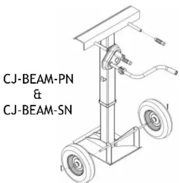
To raise and lower the top cap: models BFSJ-2748, LO-J-BEAM, LO-J, HI-J, and SP-TOP-R all utilize a ratcheting mechanism (the same handle used for moving the jack around is used for the ratchet), models SP-TOP, SJ-35, and SJ-35-EF utilize handles that are affixed to the screw hub, model CJ-BEAM uses a dual-shaft (for two speeds) hand crank mechanism, and model H-LO-J-BEAM utilizes a hydraulic jack.
Tip the stabilizing jack onto its wheels and roll it under the hitch-end (front) of the semitrailer. If using a single jack, place it on the centerline of the trailer's width. When using two jacks, place one under each front corner.
NOTE: Additional stabilizing jacks might be required under the rear corners of the semitrailer if the distance from the rear axle to the back end of the semi-trailer is more than 1/4 of the overall length of the trailer.
Adjust the height of the jack so that the top cap of the jack presses firmly against the underside of the semitrailer frame. However, the trailer landing gear must at all times remain in solid contact with the ground in order to provide support for the front end of the trailer
Jacks must be removed before backing a tractor underneath the semitrailer. To remove a trailer jack, lower the top cap so that it no longer contacts the bottom of the trailer. Tip the jack backwards and roll it away from the trailer
RECORD OF SATISFACTORY CONDITION
Record the condition of the device before putting it into service for the first time. Include observations about all features such as the handle, welds, the frame, top cap, wheels, and axle. Thoroughly photograph the unit so that all features are clearly imaged. Take close range photographs of all labels applied to the unit. Add the photographs to the record. Describe where each label is located. This record establishes satisfactory condition. During future inspections, compare your observations to the record to determine if the unit is in satisfactory condition. See Inspections & Maintenance on p. 3.
INSPECTIONS & MAINTENANCE (ALL MODELS)
Only qualified individuals trained to inspect and maintain stabilizing jacks should perform inspections and maintenance.
Inspect the jack as described in parts A and B below.
WARNING: If damage is evident, or if any problems are discovered during an inspection, immediately tag the jack "Out of service" and remove it from service UNTIL it is restored to normal operating condition.
(A) Each day inspect the jack for the following conditions:
1.) Visible damage to the screw, base, or screw hub.
2.) Free movement of the top cap.
3.) Oil leaks (H-LO-J-BEAM only).
(B) At least once per month, inspect the following components. DO NOT use the jack until it is restored to normal operating condition.:
1.) Screw threads
a. Determine if threads are adequately greased: apply a standard bearing grease to the screw threads. Fully extend the screw & apply grease liberally to the threads; then wind the screw into the jack to coat the threads. In colder climates, synthetic grease will reduce the amount of effort required to install the jack but is optional. Remove grease from the frame and handles before returning the jack to service. b. Inspect threads for severe wear or damage: if the screw wobbles inside the screw hub, the screw assembly is significantly worn and should be replaced before returning the jack to service.
3.) Screw adjustment mechanism - the mechanism should operate smoothly.
4.) Jack frame: examine the jack for cracked welds or metal fatigue.
5.) Wheels, axles, or wheel bearings: inspect for looseness, excessive wear, or damage.
6.) Handle grips: damaged, loose, or missing Install adhesive to the inside of the grips and reinstall them if they become loose.
7.) Hydraulic oil (H-LO-J-BEAM only): the oil level should be just below the fill hole of the reservoir with the jack in the lowered position. Replace the oil with hydraulic oil of viscosity grade 70 to 85 SUS at 100° F, (ISO 15 at 40° C).
8.) Labels (see "Label placement diagram" on p. 9): the jack should be labeled at all times as shown in the diagram. Replace any label that is damaged or not easily readable.
The following requirements are from OSHA standard 1910.244 titled, "Hand and Portable Powered Tools and Other Hand-Held Equipment":
1910.244(a) -- Jacks -
1910.244(a)(1) -- Loading and marking.
1910.244(a)(1)(i) -- The operator shall make sure that the jack used has a rating sufficient to lift and sustain the load.
1910.244(a)(1)(ii) -- The rated load shall be legibly and permanently marked in a prominent location on the jack by casting, stamping, or other suitable means.
1910.244(a)(2) -- Operation and maintenance.
1910.244(a)(2)(i) -- In the absence of a firm foundation, the base of the jack shall be blocked. If there is a possibility
of slippage of the cap, a block shall be placed in between the cap and the load.
1910.244(a)(2)(ii) -- The operator shall watch the stop indicator, which shall be kept clean, in order to determine the limit of travel. The indicated limit shall not be overrun.
1910.244(a)(2)(iii) -- After the load has been raised, it shall be cribbed, blocked, or otherwise secured at once.
1910.244(a)(2)(iv) -- Hydraulic jacks exposed to freezing temperatures shall be supplied with an adequate antifreeze liquid.
1910.244(a)(2)(v) -- All jacks shall be properly lubricated at regular intervals.
1910.244(a)(2)(vi) -- Each jack shall be thoroughly inspected at times which depend upon the service conditions. Inspections shall be not less frequent than the following:
1910.244(a)(2)(vi)(a) -- For constant or intermittent use at one locality, once every 6 months,
1910.244(a)(2)(vi)(b) -- For jacks sent out of shop for special work, when sent out and when returned,
1910.244(a)(2)(vi)(c) -- For a jack subjected to abnormal load or shock, immediately before and immediately thereafter.
1910.244(a)(2)(vii) -- Repair or replacement parts shall be examined for possible defects.
1910.244(a)(2)(viii) -- Jacks which are out of order shall be tagged accordingly, and shall not be used until repairs are made.
EXPLODED PARTS DIAGRAMS AND BILLS OF MATERIALS

LO-J-BEAM & LO-J-BEAM-100 exploded view and bill of materials
| ITEM | PART NO. | DESCRIPTION | QUANTITY |
| 1 | 13-514-043 | LO-J-BEAM: WELDMENT, FRAMELO-J-BEAM-100: WELDMENT, FRAME | 11 |
| 2 | 13-025-023 | HANDLE, GRIP, 1 1/8" I.D., RED | 2 |
| 3 | 13-112-001 | PIN, AXLE, STABILIZING JACKS | 1 |
| 4 | 11115 | HHCS, #2 Z PLATED, 3/8 - 16 x 3 LG. | 1 |
| 5 | 33008 | FLAT WASHER, LOW CARBON, USS,ZINC PLATED, 3/8" | 2 |
| 6 | 33012 | FLAT WASHER, LOW CARBON, ZINCFINISH, 1/2" | 1 |
| 7 | 37024 | NYLON INSERT LOCK NUT, GRADE 2,ZINC FINISH, 3/8"-16 | 1 |
| 8 | 65077 | COTTER PIN, ZINC PLATED, 1/8" X 1-1/4" | 1 |
| 9 | 13-525-001 | HANDLE ASS'Y | 1 |
| 10 | 16-132-007 | 4 X 1-1/4 SEMI STEEL WHEEL (3/8"PLAIN BORE) | 1 |
| 11 | 16-132-287 | WHEEL, ∅10" x 2 1/2", 13mm STEELHUB | 2 |

SP-TOP exploded view and bill of materials
| ITEM | PART NO. | DESCRIPTION | QUANTITY |
| 1 | 13-112-001 | PIN, AXLE, STABILIZING JACKS | 1 |
| 2 | 16-132-287 | WHEEL, 10'' × 2\ 1/2'', 13mm STEEL HUB | 2 |
| 3 | 13-514-01213-514-059 | SP-TOP: WELDMENT, FRAMESP-TOP-100: WELDMENT FRAME | 11 |
| 4 | 13-525-001 | HANDLE ASS'Y | 1 |
| 5 | 33012 | FLAT WASHER, LOW CARBON,ZINC FINISH, 1/2'' | 1 |
| 6 | 65077 | COTTER PIN, ZINC PLATED, 1/8'' × 1-1/4'' | 1 |
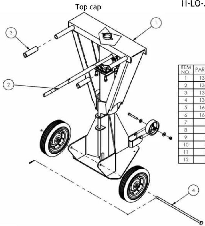
H-LO-J-BEAM exploded view and bill of materials
| ITEM NO. | PART NUMBER | DESCRIPTION | QTY. |
| 1 | 13-514-010 | WELDMENT, FRAME | 1 |
| 2 | 13-543-001 | ASSEMBLY, J-20 TON JACK & HANDLE | 1 |
| 3 | 13-025-023 | HANDLE, GRIP, 1 1/8" I.D., RED | 2 |
| 4 | 13-112-001 | PIN, AXLE, STABILIZING JACKS | 1 |
| 5 | 16-132-007 | 4 X 1-1/4 SEMI STEEL WHEEL (3/8" PLAIN BORE) | 1 |
| 6 | 16-132-287 | WHEEL, ∅10" x 2 1/2", 13mm STEEL HUB | 2 |
| 7 | 11115 | HHCS, #2 Z PLATED, 3/8 - 16 x 3 LG. | 1 |
| 8 | 11205 | HEX BOLT, GRADE A, ZINC PLATED, 1/2"-13X 1" | 3 |
| 9 | 25334 | 1/4-20 X 1" LG SOCKET SET SCREW | 2 |
| 10 | 33008 | FLAT WASHER, LOW CARBON, USS, ZINC PLATED, 3/8" | 2 |
| 11 | 37024 | NYLON INSERT LOCK NUT, GRADE 2, ZINC FINISH, 3/8"-16 | 1 |
| 12 | 65125 | COTTER PIN Z PLATED, 3/16" x 1 1/2" | 1 |
HI-J exploded view and bill of materials

| ITEM | PART NO. | DESCRIPTION | QUANTITY |
| 1 | 13-112-001 | PIN, AXLE, STABILIZING JACKS | 1 |
| 2 | 13-514-058 | WELDMENT, FRAME | 1 |
| 3 | 13-525-001 | HANDLE ASS'Y | 1 |
| 4 | 16-132-287 | WHEEL, 10'' × 2\ 1/2'', 13mm STEEL HUB | 2 |
| 5 | 33012 | FLAT WASHER, LOW CARBON, ZINC FINISH, 1/2'' | 1 |
| 6 | 65125 | COTTER PIN Z PLATED, 3/16'' × 1\ 1/2'' | 1 |
SJ-35 exploded view and bill of materials

| ITEM | PART NO. | DESCRIPTION | QUANTITY |
| 1 | 13-514-023 | SJ-35: WELDMENT, FRAME, 4 HANDLE | 1 |
| 13-514-024 | SJ-35-2H: WELDMENT, FRAME 2 HANDLE | 1 | |
| 2 | 13-025-043 | SJ-35: HANDLE/GRIP/KNOB | 4 |
| SJ-35-2H: HANDLE/GRIP/KNOB | 2 |
SJ-35-EF exploded view and bill of materials

| 10 | 65077 | COTTER PIN, ZINC PLATED, 1/8" X 1-1/4" | 1 |
| 9 | 33010 | WASHER, FLAT | 2 |
| 8 | 16-132-254 | WHEEL, 8" HARD RUBBER | 2 |
| 7 | 08-145-008 | SPECIALTY HARDWARE, SNAP HOOK, ∅1/4 | 1 |
| 6 | 13-112-006 | PIN, 8" WHEEL | 1 |
| 5 | 13-025-043 | HANDLE/GRIP/KNOB | 4 |
| 4 | 13-036-003 | HEAD ASSEMBLY, 4 HANDLES | 1 |
| 3 | 13-014-019 | FRAME, ADJUSTABLE PIPE, INNER | 1 |
| 2 | 99-112-057 | PIN HEIGHT ADJUSTMENT | 1 |
| 1 | 13-514-046 | WELDMENT, TRAILER STABILIZING JACKS | 1 |
| ITEM NO. | PART NUMBER | DESCRIPTION | QTY. |

BFSJ-2748 exploded view and bill of materials
| ITEM | PART NO. | DESCRIPTION | QUANTITY |
| 1 | 13-514-007 | FRAME, WELDMENT | 1 |
| 2 | 13-112-001 | PIN, AXLE, STABILIZING JACKS | 1 |
| 3 | 13-525-001 | HANDLE ASS'Y | 1 |
| 4 | 16-132-287 | WHEEL, ∅10" x 2 1/2", 13mm STEEL HUB | 2 |
| 5 | 33012 | FLAT WASHER, LOW CARBON, ZINC FINISH, 1/2" | 1 |
| 6 | 65125 | COTTER PIN Z PLATED, 3/16" x 1 1/2" | 1 |
| *7 | 13-025-023 | GRIP, HANDLE, RED W/ OPENING (INCLUDED WITH 13-525-001) | 2 |
LO-J & S P -TOP-R exploded view and bill of materials

| ITEM | PART NO. | DESCRIPTION | QUANTITY |
| 1 | 13-112-001 | PIN, AXLE, STABILIZING JACKS | 1 |
| 2 | 16-132-287 | WHEEL, 10'' × 2\ 1/2'', 13mm STEEL HUB | 2 |
| 3 | 13-514-019 | LO-J: WELDMENT, FRAME | 1 |
| 13-514-019 | LO-J-100: WELDMENT, FRAME | 1 | |
| 13-514-001 | SP-TOP-R: WELDMENT, FRAME | 1 | |
| 13-514-019 | SP-TOP-R-100: WELDMENT, FRAME | 1 | |
| 13-514-019 | LO-J-125: WELDMENT, FRAME | 1 | |
| 4 | 13-525-001 | HANDLE ASS'Y | 1 |
| 5 | 33012 | FLAT WASHER, LOW CARBON, ZINC FINISH, 1/2'' | 1 |
| 6 | 65125 | COTTER PIN Z PLATED, 3/16'' × 1\ 1/2'' | 1 |
CJ-BEAM-PN & CJ-BEAM-SN exploded view and bill of materials
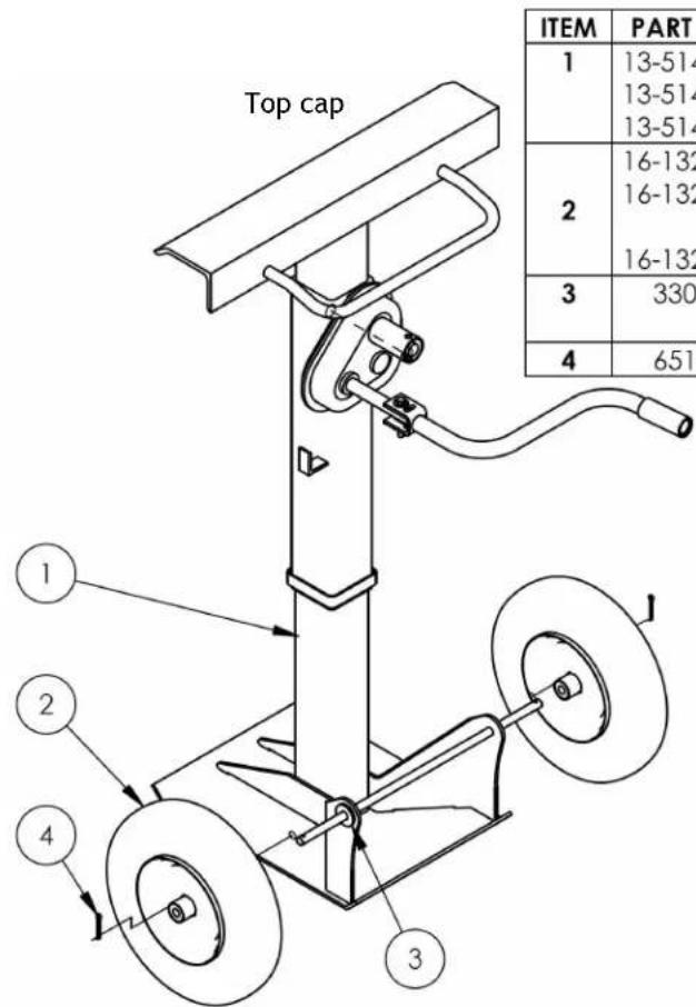
| ITEM | PART NO. | DESCRIPTION | QUANTITY |
| 1 | 13-514-055 | CJ-BEAM-PN: WELDMENT, FRAME | 1 |
| 13-514-055 | CJ-BEAM-SN: WELDMENT, FRAME | 1 | |
| 13-514-070 | CJ-BEAM-SN-AH: WELDMENT, FRAME | 1 | |
| 2 | 16-132-126 | CJ-BEAM-PN: PNEUMATIC TIRE, 4" X 16" | 2 |
| 16-132-246 | CJ-BEAM-SN: FOAM-FILLED WHEEL, 16" x 4" | 2 | |
| 16-132-246 | CJ-BEAM-SN-AH: | 2 | |
| 3 | 33016 | FLAT WASHER, LOW CARBON, USS, ZINC PLATED, 5/8" | 4 |
| 4 | 65127 | COTTER PIN Z PLATED, 3/16 x 2 | 2 |
INSTALLATION OF OPTIONAL FOAM-FILLED WHEEL (JACK-UFBL-KIT-REL)
To properly install optional foam-filled wheels, the hubs must face each other as shown in the diagrams.


LABELING DIAGRAM
Label content and location are subject to change so your product might not be labeled exactly as shown. Compare the diagram below to your RECORD OF SATUSFACTORY CONDITION. If differences between actual labeling and this diagram exist, contact TECHNICAL SERVICE. Replace all labels that are damaged, missing, or not easily readable (e.g. faded). To order replacement labels, or to inquire whether your unit is properly labeled, contact the technical service and parts department online at http://www.vestilmfg.com/parts_info.htm or by calling (260) 665-7586 and asking for the Parts Department

LIMITED WARRANTY
Vestil Manufacturing Corporation ("Vestil") warrants this product to be free of defects in material and workmanship during the warranty period. Our warranty obligation is to provide a replacement for a defective, original part covered by the warranty after we receive a proper request from the Warrantee (you) for warranty service.
Who may request service?
Only a warrantee may request service. You are a warrantee if you purchased the product from Vestil or from an authorized distributor AND Vestil has been fully paid.
Definition of "original part"?
An original part is a part used to make the product as shipped to the Warrantee.
What is a "proper request"?
A request for warranty service is proper if Vestil receives: 1) a photocopy of the Customer Invoice that displays the shipping date; AND 2) a written request for warranty service including your name and phone number. Send requests by one of the following methods:
US Mail
Vestil Manufacturing Corporation
2999 North Wayne Street, PO Box 507
Angola, IN 46703
Fax Email
(260) 665-1339
Phone
(260) 665-7586
info@vestil.com
Enter "Warranty service request"
in subject field.
In the written request, list the parts believed to be defective and include the address where replacements should be delivered. After Vestil receives your request for warranty service, an authorized representative will contact you to determine whether your claim is covered by the warranty. Before providing warranty service, Vestil will require you to send the entire product, or just the defective part (or parts), to its facility in Angola, IN.
What is covered under the warranty?
The warranty covers defects in the following original, dynamic parts: motors, hydraulic pumps, motor controllers, and cylinders. It also covers defects in original parts that wear under normal usage conditions ("wearing parts"), such as bearings, hoses, wheels, seals, brushes, and batteries.
How long is the warranty period?
The warranty period for original dynamic components is 90 days. For wearing parts, the warranty period is 90 days. Both warranty periods begin on the date Vestil ships the product to the Warrantee. If the product was purchased from an authorized distributor, the periods begin when the distributor ships the product. Vestil may, at its sole discretion, extend a warranty period for products shipped from authorized distributors by up to 30 days to account for shipping time.
If a defective part is covered by the warranty, what will Vestil do to correct the problem?
Vestil will provide an appropriate replacement for any covered part. An authorized representative of Vestil will contact you to discuss your claim.
What is not covered by the warranty?
The Warrantee (you) is responsible for paying labor costs and freight costs to return the product to Vestil for warranty service.
Events that automatically void this Limited Warranty.
- Misuse;
- Negligent assembly, installation, operation or repair;
• Installation/use in corrosive environments; - Inadequate or improper maintenance;
• Damage sustained during shipping;
• Collisions or other accidents that damage the product; - Unauthorized modifications: Do not modify the product IN ANY WAY without first receiving written authorization from Vestil.
Do any other warranties apply to the product?
Vestil Manufacturing Corp. makes no other express warranties. All implied warranties are disclaimed to the extent allowed by law. Any implied warranty not disclaimed is limited in scope to the terms of this Limited Warranty. Vestil makes no warranty or representation that this product complies with any state or local design, performance, or safety code or standard. Noncompliance with any such code or standard is not a defect in material or workmanship.
- USE & MAINTENANCE MANUAL
- TRAILER STABILIZING JACKS
- WHEN ORDERING
- REPLACEMENT PARTS
- RECEIVING INSTRUCTIONS
- USE INSTRUCTIONS - TRAILER STABILIZING JACK (ALL MODELS)
- USE AND OPERATION
- RECORD OF SATISFACTORY CONDITION
- INSPECTIONS & MAINTENANCE (ALL MODELS)
- EXPLODED PARTS DIAGRAMS AND BILLS OF MATERIALS
- SJ-35-EF EXPLODED VIEW AND BILL OF MATERIALS
- LO-J & S P -TOP-R EXPLODED VIEW AND BILL OF MATERIALS
- CJ-BEAM-PN & CJ-BEAM-SN EXPLODED VIEW AND BILL OF MATERIALS
- INSTALLATION OF OPTIONAL FOAM-FILLED WHEEL (JACK-UFBL-KIT-REL)
- LABELING DIAGRAM
- LIMITED WARRANTY
- WHO MAY REQUEST SERVICE
- DEFINITION OF "ORIGINAL PART
- WHAT IS A "PROPER REQUEST
- WHAT IS COVERED UNDER THE WARRANTY
- HOW LONG IS THE WARRANTY PERIOD
- IF A DEFECTIVE PART IS COVERED BY THE WARRANTY, WHAT WILL VESTIL DO TO CORRECT THE PROBLEM
- WHAT IS NOT COVERED BY THE WARRANTY
- EVENTS THAT AUTOMATICALLY VOID THIS LIMITED WARRANTY
- DO ANY OTHER WARRANTIES APPLY TO THE PRODUCT
Brand : Vestil
Model : LO-J
Category : Vérin stabilisateur pour remorque