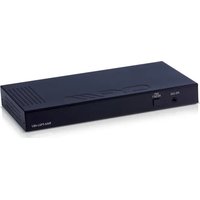
RAX-PSU-48V - Power Supply CYP - Free user manual and instructions
Find the device manual for free RAX-PSU-48V CYP in PDF.


| Product Type | Power Supply Unit |
| Brand | CYP |
| Model | RAX-PSU-48V |
| Input Voltage | 100-240 VAC, 50/60 Hz |
| Output Voltage | 48 VDC |
| Output Current | Up to 5 A (typical) |
| Output Power | 240 W |
| Dimensions (W x D x H) | 200 x 100 x 50 mm (approx.) |
| Weight | 1.2 kg (approx.) |
| Cooling Method | Convection cooled |
| Protections | Overload, short circuit, overvoltage |
| Operating Temperature | 0°C to 40°C |
| Storage Temperature | -20°C to 60°C |
| Input Connector | IEC C14 (typical) |
| Output Connector | Screw terminal or DC jack |
| Safety Certifications | CE, RoHS |
| Usage | Indoor use only |
| Mounting | Desktop or wall-mountable (brackets included) |
Frequently Asked Questions - RAX-PSU-48V CYP
User questions about RAX-PSU-48V CYP
0 question about this device. Answer the ones you know or ask your own.
Ask a new question about this device
Download the instructions for your Power Supply in PDF format for free! Find your manual RAX-PSU-48V - CYP and take your electronic device back in hand. On this page are published all the documents necessary for the use of your device. RAX-PSU-48V by CYP.
USER MANUAL RAX-PSU-48V CYP
RAX-PSU-48V
48V DC Power Manager
OPERATION MANUAL
DISCLAIMERS
The information in this manual has been carefully checked and is believed to be accurate. CYP (UK) Ltd assumes no responsibility for any infringements of patents or other rights of third parties which may result from its use.
CYP (UK) Ltd assumes no responsibility for any inaccuracies that may be contained in this document. CYP (UK) Ltd also makes no commitment to update or to keep current the information contained in this document.
CYP (UK) Ltd reserves the right to make improvements to this document and/or product at any time and without notice.
COPYRIGHT NOTICE
No part of this document may be reproduced, transmitted, transcribed, stored in a retrieval system, or any of its part translated into any language or computer file, in any form or by any means—electronic, mechanical, magnetic, optical, chemical, manual, or otherwise—without express written permission and consent from CYP (UK) Ltd.
© Copyright 2011 by CYP (UK) Ltd.
All Rights Reserved.
Version 1.1 August 2011
TRADEMARK ACKNOWLEDGMENTS
All products or service names mentioned in this document may be trademarks of the companies with which they are associated.
SAFETY PRECAUTIONS
Please read all instructions before attempting to unpack, install or operate this equipment and before connecting the power supply.
Please keep the following in mind as you unpack and install this equipment:
- Always follow basic safety precautions to reduce the risk of fire, electrical shock and injury to persons.
- To prevent fire or shock hazard, do not expose the unit to rain, moisture or install this product near water.
- Never spill liquid of any kind on or into this product.
- Never push an object of any kind into this product through any openings or empty slots in the unit, as you may damage parts inside the unit.
- Do not attach the power supply cabling to building surfaces.
- Use only the supplied power supply unit (PSU). Do not use the PSU if it is damaged.
- Do not allow anything to rest on the power cabling or allow any weight to be placed upon it or any person walk on it.
- To protect the unit from overheating, do not block any vents or openings in the unit housing that provide ventilation and allow for sufficient space for air to circulate around the unit.
REVISION HISTORY
VERSION NO. DATE SUMMARY OF CHANGE
| v1.00 19/03/2018 First release | ||
CONTENTS
- Introduction......6
- Applications ......6
- Package Contents ......6
- System Requirements ......6
- Features......7
- Operation Controls and Functions .....8
6.1 Front Panel 8
6.2 Rear Panel....9
6.3 RS-232 Protocol....10
6.4 RS-232 and Telnet Commands......10
6.5 Telnet Control....12
6.6 WebGUI Control ....13
- Connection Diagram ...... 18
- Specifications....19
- Acronyms......19
1. INTRODUCTION
This 8-Port 48V DC Power Manager is a DC power splitter which can distribute up to 300 milliamps of 48 volt power to up to eight connected devices via 2-pin terminal block connections (115 watts total across all 8 outputs). Ideal for professional applications, this unit provides direct per-port power control via WebGUI, Telnet or RS-232. An integrated, battery backed-up, clock allows for detailed power scheduling based on a repeating daily/weekly schedule, or single events. Up to 2 fans may be connected and their speed can be either automatically controlled based on a detected temperature, or set to a single static speed. Detailed status information about the power input, each power output, current fan speed, and system temperature is provided to give a comprehensive system overview.
2. APPLICATIONS
Entertainment Rooms & Home Theaters
Showrooms & Demo Rooms
Lecture Hall Presentations
■ Public Commercial Displays
AV equipment and control rooms
3. PACKAGE CONTENTS
1×8-Port 48V DC Power Manager
1×48V/3.12A DC Power Adaptor
1×Power Cord
8×2-pin Terminal Block to 48V DC Power Adaptor Cable
1×4-pin Terminal Block
1×3.5mm to 9-pin D-sub Adaptor Cable
1×Operation Manual
4. SYSTEM REQUIREMENTS
48V powered equipment requiring less than 14 watts of power using 2-pin 3.5mm terminal block terminated power cables.
5. FEATURES
Power management system providing voltage-controlled current (48V) on each output
Battery backed up clock for scheduling power events
Integrated WebGUI for control and power analysis
Unit's overall maximum power consumption is only 143 watts
Supports 8 power output ports with professional 2-pin 3.5mm terminal block connectors
115 watts of total power provided across all 8 outputs (14 watts per output, or up to 45 watts over a single port, if additional ports have been turned off)
6. OPERATION CONTROLS AND FUNCTIONS
6.1 Front Panel

1 RS-232: Connect directly to your PC/laptop using a 3.5mm mini-jack to 9-pin adapter to send RS-232 commands to control the unit.
2 ISP/RESET: This button has multiple functions, see below.
2a ISP MODE: Press and hold this button while powering the unit on to enter ISP mode.
2b FACTORY RESET: Press and hold this button for 5+ seconds, after the unit is already powered on, to perform a full factory reset of the unit.
2c REBOOT: Momentarily press this button, after the unit is already powered on, to reboot the unit.
6.2 Rear Panel

1 48V POWER OUT & LEDs 1\~8: Connect power cables with 3.5mm 2-pin terminal blocks from units requiring 48V power. Up to 8 devices can be powered. When power is available from a port, the associated LED will be green. When a power port is disabled its LED will turn off.
2 12V FAN A/B: Connect to a dedicated dual-fan power and control cable. Fan speed can be controlled via WebGUI, Telnet, or RS-232.
3 SERV.: This slot is reserved for firmware update use only.
4 CONTROL: Connect directly, or through a network switch, to your PC/laptop to control the unit via Telnet/WebGUI.
5 DC 48V: Plug the 48V DC power adapter into the unit and connect it to an AC wall outlet for power.
6 ON/OFF: Flip this switch to turn the unit ON or OFF after connecting a 48V power source.
6.3 RS-232 Protocol
| UNIT | |
| Pin Definition Pin Definition | |
| 1 NC 1 NC | |
| 2 TxD 2 RxD | |
| 3 RxD 3 TxD | |
| 4 NC 4 NC | |
| 5 GND 5 GND | |
| 6 NC 6 NC | |
| 7 NC 7 NC | |
| 8 NC 8 NC | |
| 9 NC 9 NC | |
6.4 RS-232 and Telnet Commands
| COMMAND DESCRIPTION AND PARAMETERS | |
| HELP Show the full command list. | |
| ? Show the full command list. | |
| HELP N1 Show a description of command N1.N1 = {Command Name} | |
| IPCFG | Display the current IP configuration. |
| IPSTATIC N1 N2 N3 | Set the full static IP configuration.N1 = X.X.X.X [X = 0 ~ 255, IP Address]N2 = X.X.X.X [X = 0 ~ 255, Netmask]N3 = X.X.X.X [X = 0 ~ 255, Gateway] |
| IPDHCP N1 | Enable or disable DHCP for obtaining the unit's IP configuration.N1 = ON, OFF |
| VERSION | Show the unit's firmware version. |
| FADEFAULT | Reset the unit to the factory defaults. |
| REBOOT | Reboot the unit. |
| PWR N1 N2 Enable or disable | power output N1.N1 = 1 ~ 8 [Port number]N2 = ON, OFF |
| PWR N1 NAME N2 Rename power output N1.N1 = 1 ~ 8 [Port number]N2 = {Name String} [16 characters max] | |
| PWR_STATUS N1 Show the current power state (volts, watts, amps) of power output N1.N1 = 1 ~ 8 [Port number] | |
| TEMPERATURE Show details of the unit's temperature and fan control settings. | |
| FAN_SET N1 Set non-“Auto Mode” fan speed or enable “Fan Auto Mode”.Available values for N1:0 ~ 100 [Disable Fan Auto Modeand set the fan speed to theselected percentage]AUTO [Enable Fan Auto Mode] | |
| FAN_SET N1 N2 N3 Set the fan speed and temperature threshold for the selected automatic speed tier.Available values for N1:AUTO_LOW [Auto fan setting to adjust]AUTO_MIDAUTO_HIGHN2 = 0 ~ 100 [Temperature threshold in °C]N3 = 0 ~ 100 [Fan speed in percent] | |
Note: Commands will not be executed unless followed by a carriage return. Commands are not case-sensitive.
6.5 Telnet Control
Before attempting to use Telnet control, please ensure that both the unit and the PC/Laptop are connected to the same active networks.
| To access the Command Line Interface (CLI) | |
| In Windows 7 | Click Start, type “cmd” in the search field, and press Enter. |
| In Windows XP | Click Start > Run, type “cmd”, and press Enter. |
| In Mac OS X | Click Go > Applications > Utilities > Terminal. |
Once in the Command Line Interface (CLI) type "Telnet" followed by the IP address of the unit (and the port number if it is non-standard) and then hit "Enter". See below for reference.
Microsoft Windows [Version 6.1.7601]
Copyright (c) 2009 Microsoft Corporation. All rights reserved.
C:\Users\Administrator>telnet 192.168.1.50 23
This will connect us to the unit we wish to control. Type "help" to list the available commands.
Note: The unit's default IP address is 192.168.1.50. If the IP address is changed then the IP address required for Telnet access will also change accordingly.
6.6 WebGUI Control
Device Discovery APP
Please obtain the Device Discovery software from your authorised dealer and save it in a directory where you can easily find it.
Connect the unit and your PC/Laptop to the same active network and execute the Device Discovery software. Click on "Find Devices on Network" and a list of devices connected to the local network will show up indicating their current IP address.

Note: The unit's default IP address is 192.168.1.50.
By clicking on one of the listed devices you will be presented with the network details of that particular device.

(1) IP Mode: If you choose, you can alter the static IP network settings for the device, or switch the unit into DHCP mode to automatically obtain proper network settings from a local DHCP server. To switch to DHCP mode, please select DHCP from the IP mode drop-down, then click "Save" followed by "Reboot".
(2) WebGUI Hotkey: Once you are satisfied with the network settings, you may use them to connect via Telnet or WebGUI. The network information window provides a convenient link to launch the WebGUI directly.
WebGUI Overview
After connecting to the WebGUI's address in a web browser, log into the unit by entering the appropriate user name and password.
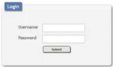
All primary functions of this unit are controllable via the built in WebGUI, including Status, Device Settings, Schedule, and System settings. The individual functions will be introduced in the following section.
6.6.1 Status
This tab displays the current status of the various components of the unit in real-time.

(1) Power In: Displays the voltage, current and wattage of the unit's main power supply.
(2) Power Out: Displays the voltage, current and wattage of each of the 8 individual power outputs.
(3) System Temperature: Displays the unit's temperature as measured at 3 locations inside the case on the PCB.
(4) System Fan: Displays the current state of 2 external fans (optional) including individual fan RPM, and the current fan speed thresholds, if auto mode is enabled.
6.6.2 Device Settings
This tab provides controls for all 8 power output ports as well as control over the optional external fans' speed and temperature thresholds.
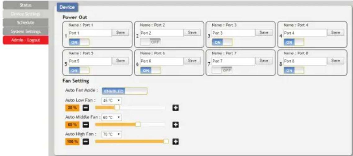
(1) Power Out: This section provides control over each individual power output. The outputs may be turned on, turned off, and renamed.
(2) Fan Setting: This section provides controls for any connected fans. When Auto Fan Mode is enabled the fan speed will be controlled based on the 3, user set, temperature thresholds and speed selections. The preferred fan speed at each threshold is also user configurable. If Auto Fan Mode is disabled, the fan speed can be set as a static percentage of maximum power. If 2 fans are connected to the unit, both will follow the same settings.
Note: The highest of the 3 System Temperature measurements is used to determine which Auto Fan Mode speed (low, middle, or high) is active when Auto Fan Mode is enabled.
6.6.3 Schedule
The Schedule tab provides multiple ways to automate and schedule the powering on and off of any of the 8 power ports on this unit.

(1) Repeat Mode: Items in this section will execute at their set times on the selected days (Sunday through Saturday) every week as long as they are marked as "Active".
(2) Once Mode: Items in this section are scheduled to occur a single time on a specific date at the specified time. Each item will automatically change to "None Active" after they have been executed once.

Note: Each schedule item must be set as "Active" for it to activate at the scheduled time.
6.6.4 System Settings
This tab provides system configuration options including changing the network settings, downloading/restoring saved system configurations, modifying the username and password, system time setting, and updating the firmware.

(1) Network: This section allows for setting the unit to either Static or DHCP mode for its IP information. When in Static mode, the IP, Netmask, and Gateway may be set manually.
(2) Web User Setting: This section allows for the login password to be changed. The username is "admin" and the default password is also "admin".
(3) System Time: This section allows user to set the system time and date.
Note: The new setting will not take effect until "Save" is clicked.
(4) Download Current Configuration: This section allows the user to download the current system configuration to a local PC for restoration later.
(5) Restore Configuration: This section allows user to restore a previously downloaded system configuration.
(6) Firmware Upgrade: This section allows for new firmware to be uploaded into the unit.
7. CONNECTION DIAGRAM
![graph TD A["RS-232 Equipped PC/Laptop"] --> B["LANRS-232"] B --> C["48V Power Outputs"] C --> D["Up to 8 Powered Device Units"] C --> E["12V Power Outputs"] D --> F["Rackmount Cooling Fan"] E --> G["Rackmount Cooling Fan"] H["Power Supply"] --> I["LANRS-232"] I --> J["48V Power Outputs"] J --> K["Ra…](/content/2026/07/1437078/images/70cf067dc869876093553842dd3fa610468bcbe8fe5ef4c47fff44a63cee1863.jpg)
8. SPECIFICATIONS
Output Ports 8×48V Power [2-pin Terminal Blocks]
2×12V Power [4-pin Terminal Block]
Control Interfaces 1×RS-232 [3.5mm]
1×IP Control [RJ-45]
Baud Rate 19200bps
Power Supply 48V/3.12A DC (US/EU standards, CE/FCC/UL
certified)
ESD Protection Human Body Model:
±12kV (Air Discharge)
±8kV (Contact Discharge)
Silkscreen Colour Black
Operating Temperature 0°C - 40°C/32°F - 104°F
Storage Temperature -20°C - 60°C / -4°F - 140°F
Relative Humidity 20 - 90% RH (Non-condensing)
Power Consumption 143W
9. ACRONYMS
| ACRONYM | COMPLETE TERM |
| CLI | Command Line Interface |
| DC | Direct Current |
| GUI | Graphical User Interface |
| IP | Internet Protocol |

CYP (UK) Ltd., Unit 7, Shepperton Business Park, Govett Avenue, Shepperton, Middlesex, TW17 8BA
Tel: +44 (0) 20 3137 9180 | Fax: +44 (0) 20 3137 6279
Email: sales@cypeurope.com
www.cypeurope.com
v1.00

- RAX-PSU-48V
- DISCLAIMERS
- COPYRIGHT NOTICE
- TRADEMARK ACKNOWLEDGMENTS
- SAFETY PRECAUTIONS
- REVISION HISTORY
- CONTENTS
- INTRODUCTION
- APPLICATIONS
- PACKAGE CONTENTS
- SYSTEM REQUIREMENTS
- FEATURES
- OPERATION CONTROLS AND FUNCTIONS
- 6.1 FRONT PANEL
- 6.2 REAR PANEL
- 6.3 RS-232 PROTOCOL
- 6.4 RS-232 AND TELNET COMMANDS
- 6.5 TELNET CONTROL
- 6.6 WEBGUI CONTROL
- DEVICE DISCOVERY APP
- WEBGUI OVERVIEW
- 6.6.1 STATUS
- 6.6.2 DEVICE SETTINGS
- 6.6.3 SCHEDULE
- 6.6.4 SYSTEM SETTINGS
- CONNECTION DIAGRAM
- SPECIFICATIONS
- ACRONYMS
Brand : CYP
Model : RAX-PSU-48V
Category : Power Supply