
P-MST-8T-200 - Boîtier de connexion électrique Panduit - Free user manual and instructions
Find the device manual for free P-MST-8T-200 Panduit in PDF.


| Brand | Panduit |
| Model | P-MST-8T-200 |
| Product Type | Managed Network Switch |
| Number of Ports | 8 |
| Port Type | 10/100/1000Base-T |
| Form Factor | Desktop / 1U Rackmount |
| Dimensions (W x D x H) | 330 x 200 x 44 mm |
| Weight | 2.5 kg |
| Power Supply | AC 100-240V, 50-60Hz, internal |
| Power Consumption | 25W max |
| Switching Capacity | 16 Gbps |
| Management | Web, CLI, SNMP |
| VLAN Support | Yes, up to 256 VLANs |
| Quality of Service | Yes, with 8 priority queues |
| Cooling | Fanless passive cooling |
| Operating Temperature | 0°C to 50°C |
| Storage Temperature | -20°C to 85°C |
| Safety Certifications | CE, FCC, RoHS |
| Maintenance | Keep in clean, dry environment; clean dust with soft cloth; avoid liquids. |
| Spare Parts | Power supply unit, replacement fan (if applicable) |
Frequently Asked Questions - P-MST-8T-200 Panduit
User questions about P-MST-8T-200 Panduit
0 question about this device. Answer the ones you know or ask your own.
Ask a new question about this device
Download the instructions for your Boîtier de connexion électrique in PDF format for free! Find your manual P-MST-8T-200 - Panduit and take your electronic device back in hand. On this page are published all the documents necessary for the use of your device. P-MST-8T-200 by Panduit.
USER MANUAL P-MST-8T-200 Panduit
MST MOUNTING OPTIONS
The Multiport Service Terminal (MST) can be installed using any one of several standard Outside Plant (OSP) enclosures. However, it doesn't necessitate an OSP enclosure and can be mounted openly on a pole or strand. The following describes various mounting options.
HAND-HOLE MOUNTING (below ground)
A hand-hole enclosure (Figure 1) an underground muunting option for the MST and similar product, ensuring a secure installation that aligns flush with the ground surface. The enclosure comprises a base unit and a top cover. The base unit is securely mounted in the ground, with cables and conduit entering from the bottom.
Figure 1: Typical Hand-Hole Mounting

PEDESTAL MOUNTING (at final grade)
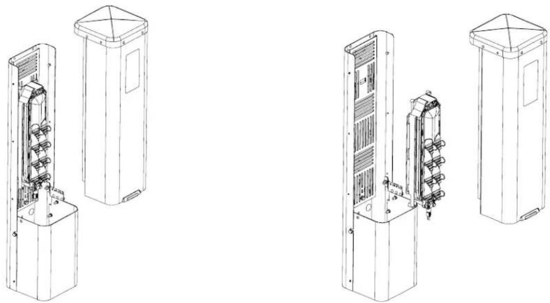
Pedestal enclosures, as depicted in Figure 2, offer a solution for installing the MST at ground level. These enclosures are comprised of a base assembly and a top cover. The base assembly is partially mounted in the ground, with cables and conduit entering from the bottom.
Figure 2: Pedestal Mounting
POLE-MOUNTING (aerial)
The MST can be affixed to a utility pole, demonstrated in figure 3. The Multiport Service Terminal Mounting Case (MC) can be secured to the pole using lag screws or construction screws. Apart from these fasteners, no additional components are needed for pole-mounting.
Figure 3: Pole-Mount Installation

STRAND-MOUNTING (aerial)
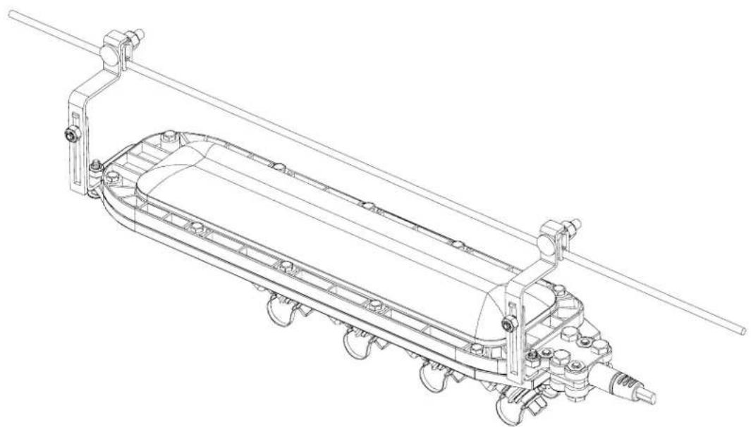
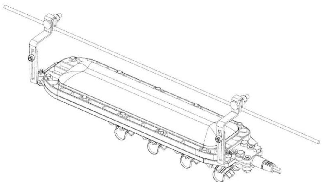
A kit comprising a strand-mount bracket (P-MSW-ASB) facilitates aerial mounting of the MST from an overhead strand, demonstrated in Figure 4. These brackets are installed onto the MC and subsequently clamped securely onto the strand. The MST conveniently snaps into place within the MC.
Figure 4: Strand-Mount Installation
Installing the MST and Multiport Service Terminal Mounting Case (MC)
The MC accompanies every MST unit for effortless installation. This bracket enables secure mounting of the MST onto diverse surfaces. Figure 5 illustrates the options for attaching the MC to different surfaces using various fasteners. The MC features multiple holes and slots to accommodate screws, nails, and cable ties, offering flexibility in fastening methods. Choose the preferred method to firmly secure the MC onto the chosen mounting surface.
Figure 5: The Multiport Service Terminal Mounting Case Installation (MC)

Once the MC has been mounted, proceed to install the MST within it according to the guidelines depicted in Figure 6. Begin by inserting the cable end of the MST into the MC, then push the front of the MST into the MC until the security latch securely snaps closed.
Figure 6: Installing the MST in the Mounting Case

If the MST will be supported from a strand, secure the front of the MST to the MC with cables ties as shown in Figure 7.
Figure 7: Installing the MST supported from a strand
Connecting Drop Cable to MST Optical Port
Use the following procedure to connect a drop cable to an optical port on the MST enclosure:
- Unscrew the dust cap from the drop connector.
-
Inspect the drop cable connector O-rings for dryness and apply O-ring lubricant to each O-ring if dry. Note: The connector O-rings are pre-lubricated by the factory and should not require additional lubrication for initial assembly.
-
Use the 216B key tool to unscrew the dust cap from the MST optical port.
-
Clean both the optical port adapter and the drop cable connector.
-
Align the drop cable connector with the optical port as shown in Figure 8. The pointer on the drop cable connector should line up with the notch on the optical port.
-
Insert the drop cable connector into the optical port. If the drop cable connector does not insert all the way to the bottom of the port, rotate the drop cable connector slightly to either side until it slides freely into place.
Figure 8: Connecting Drop Cable to MST Optical Port

For Instructions in Local Languages and Technical Support:
www.panduit.com
PANDUIT
www.panduit.com
E-mail:


Brand : Panduit
Model : P-MST-8T-200
Category : Boîtier de connexion électrique