
NTM302SS - Range hood NuTone - Free user manual and instructions
Find the device manual for free NTM302SS NuTone in PDF.


| Product Type | Under-cabinet Range Hood |
| Brand | NuTone |
| Model | NTM302SS |
| Color / Finish | Stainless Steel |
| Width | 30 inches (76.2 cm) |
| Depth | Approximately 18 inches (45.7 cm) |
| Height | Adjustable from 6 to 12 inches (15.2 to 30.5 cm) |
| Weight | Approximately 25 lbs (11.3 kg) |
| Power Supply | 120V, 60Hz, 15A circuit recommended |
| Lighting | 2 x 40W incandescent or LED equivalent (not included) |
| Fan Speeds | 3 speeds (Low, Medium, High) |
| Maximum Airflow | Approximately 400 CFM (cubic feet per minute) |
| Noise Level | Approximately 55 dB on high speed |
| Ducting Type | Convertible (vented or recirculating with charcoal filter) |
| Duct Size | 6 inches round (15.2 cm) |
| Filter Type | Aluminum mesh grease filter (dishwasher safe) |
| Charcoal Filter | Optional for recirculating mode (model NTMCHF30) |
| Controls | Push buttons with light and fan controls |
| Installation Type | Under cabinet or wall mount with canopy |
| Energy Star Rated | No (standard model) |
| Warranty | 1 year limited parts and labor |
Frequently Asked Questions - NTM302SS NuTone
User questions about NTM302SS NuTone
0 question about this device. Answer the ones you know or ask your own.
Ask a new question about this device
Download the instructions for your Range hood in PDF format for free! Find your manual NTM302SS - NuTone and take your electronic device back in hand. On this page are published all the documents necessary for the use of your device. NTM302SS by NuTone.
USER MANUAL NTM302SS NuTone
HB0112
NTM SERIES
READ AND SAVE THESE INSTRUCTIONS
INSTALLER: LEAVE THIS MANUAL WITH HOMEOWNER. HOMEOWNER: USE AND CARE INFORMATION ON PAGES 9-10.
Broan-NuTone LLC; Hartford, Wisconsin www.nutone.com 1-888-336-3948 Venmar Ventilation ULC; Drummondville, Québec www.nutone.ca 1-877-896-1119 REGISTER YOUR PRODUCT ON LINE AT: www.nutone.com/register or www.nutone.ca/register
IMPORTANT SAFETY INSTRUCTIONS
⚠ WARNING
TO REDUCE THE RISK OF FIRE, ELECTRIC SHOCK OR INJURY TO PERSON(S), OBSERVE THE FOLLOWING:
- Use this unit only in the manner intended by the manufacturer. If you have questions, contact the manufacturer at the address or telephone number listed in the warranty.
- Before servicing or cleaning unit, switch power off at service panel and lock service disconnecting means to prevent power from being switched on accidentally. When the service disconnecting means cannot be locked, securely fasten a prominent warning device, such as a tag, to the service panel.
- Installation work and electrical wiring must be done by qualified personnel in accordance with all applicable codes and standards, including fire-rated construction codes and standards.
- Sufficient air is needed for proper combustion and exhausting of gases through the flue (chimney) of fuel burning equipment to prevent backdrafting. Follow the heating equipment manufacturer's guidelines and safety standards such as those published by the National Fire Protection Association (NFPA) and the American Society for Heating, Refrigeration and Air Conditioning Engineers (ASHRAE) and the local code authorities.
- When cutting or drilling into wall or ceiling, do not damage electrical wiring and other hidden utilities.
- Ducted fans must always be vented to the outdoors.
- Do not use this unit with any solid-state speed control device.
- To reduce the risk of fire, use only metal ductwork.
- This unit must be grounded.
- When performing installation, servicing or cleaning the unit, it is recommended to wear safety glasses and gloves.
- When applicable local regulations comprises more restrictive installation and/or certification requirements, the aforementioned requirements prevail on those of this document and the installer agrees to conform to these at his own expenses.
TO REDUCE THE RISK OF A RANGE TOP GREASE FIRE:
a) Never leave surface units unattended at high settings. Boilovers cause smoking and greasy spillovers that may ignite. Heat oils slowly on low or medium settings.
b) Always turn hood ON when cooking at high heat or when flaming foods (i.e.: Crêpes Suzette, Cherries Jubilee, Peppercorn Beef Flambé).
c) Clean ventilating fans frequently. Grease should not be allowed to accumulate on fan, filters or in exhaust ducts.
d) Use proper pan size. Always use cookware appropriate for the size of the surface element.
⚠ WARNING
TO REDUCE THE RISK OF INJURY TO PERSON(S) IN THE EVENT OF A RANGE TOP GREASE FIRE, OBSERVE THE FOLLOWING*:
- SMOTHER FLAMES with a close fitting lid, cookie sheet or metal tray, then turn off the burner. BE CAREFUL TO PREVENT BURNS. IF THE FLAMES DO NOT GO OUT IMMEDIATELY, EVACUATE AND CALL THE FIRE DEPARTMENT.
- NEVER PICK UP A FLAMING PAN — You may be burned.
- DO NOT USE WATER, including wet dishcloths or towels — This could cause a violent steam explosion.
- Use an extinguisher ONLY if:
A. You own a Class ABC extinguisher and you know how to operate it.
B. The fire is small and contained in the area where it started.
C. The fire department has been called.
D. You can fight the fire with your back to an exit.
* Based on "Kitchen Fire Safety Tips" published by NFPA.
CAUTION
- For indoor use only.
- For general ventilating use only. Do not use to exhaust hazardous or explosive materials and vapors.
- To avoid motor bearing damage and noisy and/or unbalanced impellers, keep drywall spray, construction dust, etc. off power unit.
- Your hood motors have a thermal overload which will automatically shut off the motors if it becomes overheated. The motors will restart when it cools down. If the motors continues to shut off and restart, have the hood serviced.
- The bottom of the hood MUST NOT BE LESS than 26" and at a maximum of 30" above cooktop for best capture of cooking impurities. For a gas range, the bottom of the hood MUST NOT BE LESS than 28" above cooktop.
- Two installers are recommended because of the size of this hood.
- To reduce the risk of fire and to properly exhaust air, be sure to duct air outside — Do not exhaust air into spaces within walls or ceiling or into attics, crawl space or garage.
- Because of the high exhausting capacity of this hood, you should make sure enough air is entering the house to replace exhausted air by opening a window close to or in the kitchen.
- Please read specification label on product for further information and requirements.
Please take note this manual uses the following symbols to emphasize particular information:
WARNING
Identifies an instruction which, if not followed, might cause serious personal injuries including possibility of death.
CAUTION
Denotes an instruction which, if not followed, may severely damage the unit and/or its components.
NOTE: Indicates supplementary information needed to fully complete an instruction.
TABLE OF CONTENT
- INSTALL DUCTWORK ....3
- PREPARE THE INSTALLATION 4
- PREPARE THE HOOD .....5-6
- INSTALL THE HOOD 6
- CONNECT WIRING....7
- LIGHT BULBS 8
- CLEANING AND MAINTENANCE 9-10
- OPERATION 10
- WIRING DIAGRAM 11
- SERVICE PARTS 11
- WARRANTY 12
1. INSTALL DUCTWORK
Choose where the ductwork will run between the hood and outdoors.
A straight, short duct run will allow the hood to perform most efficiently.
Long duct runs and elbows will reduce the performance of the hood. Use as few of them as possible.
Install proper-sized ductwork, elbow(s) and roof or wall cap for the type of discharge chosen. Use 2" metal foil duct tape to seal joints.
VERTICAL DISCHARGE
USING 6" ROUND DUCT
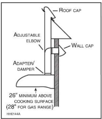
VERTICAL DISCHARGE USING 3 1/4 " X 10" DUCT
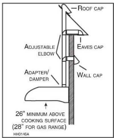
HORIZONTAL DISCHARGE USING 3 1/4 " X 10" DUCT

NOTE: We recommend to install the hood at a minimum of 26" from an electric range and at 28" from a gas range. For optimal performance, the hood should not be installed more than 30" from cooking surface.
2. PREPARE INSTALLATION
WARNING
When performing installation, servicing or cleaning the unit, it is recommended to wear safety glasses and gloves.
Tools needed to install the range hood:
- Phillips screwdriver no. 2
- Pair of long nose pliers
- Flat blade screwdriver (to open the electrical knockout hole)
- Scissors (to cut metal foil duct tape)
- Wire stripper
Make sure the following items are included:
- Hood
- Adapter/dampers: Horizontal 3¼" x 10", vertical 3¼" x 10" and vertical 6" round
- Halogen bulbs (2) (JC type, 12 V, 20 W, G4 base)
- Parts bag including: 1 wire clamp, 4 no. ST4.8 x 15 mm mounting screws, 3 wire connectors
NOTE: If the bottom of the cabinet is recessed, attach wood strips (not included), as shown beside, in order to properly install the range hood under the cabinet. The wood strips must be as thick as recess.

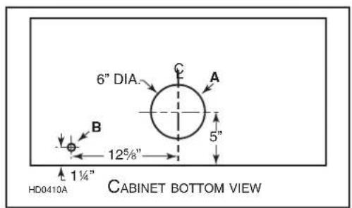
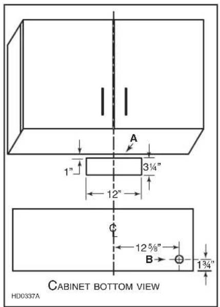
Cut-out the openings for duct (A) and power cable (B), in cabinet or wall, according to the direction of discharge chosen. See illustrations below.
VERTICAL DISCHARGE (6"ROUND DUCT)
VERTICAL DISCHARGE (3¼" x 10" DUCT)

HORIZONTAL DISCHARGE
3. PREPARE THE HOOD
3.1 ALL INSTALLATIONS
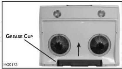
- Lay the hood on its top on a table. Use a piece of cardboard to avoid damaging the table or the hood. Slide the main grease cup out and set aside. Remove the bottom panel 7 retaining screws. Set bottom panel and screws aside.
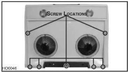
- Remove both electrical box cover retaining screws. Remove cover and set aside with screws. Turn the hood over and punch out the wiring knock-out located on TOP of the unit and install the wire clamp (included).

3.2 VERTICAL DISCHARGE ONLY
- Remove the shutoff plate 10 retaining screws. Set the screws aside and discard the shutoff plate.

6" ROUND DUCT INSTALLATION
- Mount the 6" round adapter/damper on top of the hood, using the 10 screws previously removed.

3¼" x 10" DUCT INSTALLATION
- Mount the 3 1/4 " x 10" adapter/damper on top of the hood, using the 10 screws previously removed.

3. PREPARE THE HOOD (CONT'D)
3.3 HORIZONTAL DISCHARGE ONLY
- Remove the large shutoff plate 5 retaining screws located on the BACK of the hood. Discard the shutoff plate and its screws.
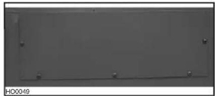
- Remove the small shutoff plate 10 retaining screws located INSIDE the back of the hood. Set the screws aside and discard the shutoff plate.

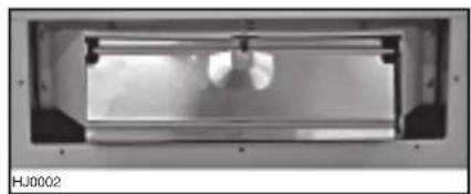
- Using the 10 screws previously removed in step 2, install the adapter in the inside back of the hood.

- Install the damper in the adapter, as shown beside.
4. INSTALL THE HOOD
Run power cable to installation location. Place the hood close to its location and insert the cable in the hood.
Place the hood under the cabinet and tighten the wire clamp to secure the cable. Make sure the adapter/damper assembly enters the ducting and the damper opens freely. Secure the hood by installing and tightening the 4 no. ST4.8 x 15 mm mounting screws (included) completely at sides locations (A).

5. CONNECT WIRING
WARNING
Risk of electrical shock. Electrical wiring must be done by qualified personnel in accordance with all applicable codes and standards. Before connecting wires, switch power off at service panel and lock service disconnecting means to prevent power from being switched on accidentally.
- Connect cable to range hood wiring using included wire connectors. Connect BLACK to BLACK, WHITE to WHITE and GREEN or BARE wire to GREEN wire.
- Reinstall wiring box cover using both screws previously removed in step 3.1.

- Reinstall bottom panel using the 7 screws previously removed in step 3.1. Make sure both grease guides are aligned with the holes.
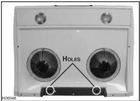
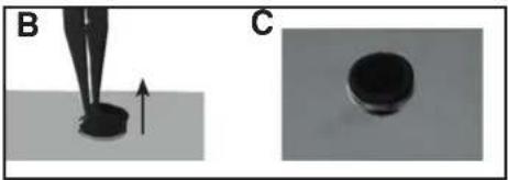
- Using long nose pliers, pull out the end of each grease guides (B). Then set them in such a way their flange slightly protrudes above the bottom panel surface (C).
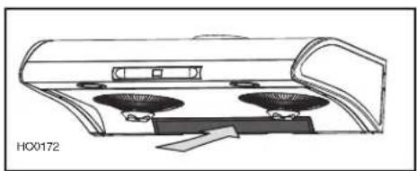
- Slide the main grease cup back in.
6. LIGHT BULBS
WARNING
Make sure power is switched off at service panel before carrying out any operation on the hood.
This range hood requires two UL approved halogen bulbs (JC type, 12 V, 20 W, G4-base), included. To replace bulbs:
CAUTION
Take care not to damage the hood finish while using the screwdriver.
- Carefully insert the blade of a small flat blade screwdriver between light cover and rim and gently pry out light assembly.
WARNING
In order to prevent the risk of personal injury, the halogen lamps must cool down before removing them.

- Remove light cover from light assembly and set aside.

- Replace bulb with a new JC type, 12 V, 20 W Max, G4 base halogen bulb.
CAUTION
Do not touch replacement bulb with bare hands!
- To reinstall the light cover, insert the 3 light cover tabs in the light assembly slots and gently push until secured.

7. CLEANING AND MAINTENANCE
- Slide out main grease cup.

- Disengage the small grease guard cups from the metal guards by turning counterclockwise and remove.
- Remove the screw retaining the metal guards to the hood.
- Remove the metal guards from the hood. Then remove the bottom panel.


- Unscrew the clips and remove the wheel grease collector.
- Remove the wheel center cap.
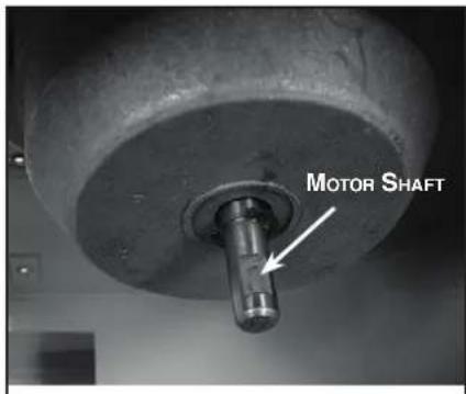
- Loosen the wheel set screw in order to disengage the wheel from its motor shaft.
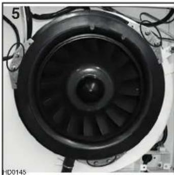


Let soak all removed parts in warm water with soft soap for 30 minutes. Rinse and dry completely before reinstalling.
NOTE: When reinstalling the wheel, align the end of the set screw with the flat part of the motor shaft.
7. CLEANING AND MAINTENANCE (CONT'D)
STAINLESS STEEL CLEANING:
Do:
- Regularly wash with clean cloth or rag soaked with warm water and mild soap or liquid dish detergent.
• Always clean in the direction of original polish lines. - Always rinse well with clear water (2 or 3 times) after cleaning. Wipe dry completely.
- You may also use a specialized household stainless steel cleaner.
Don't:
- Use any steel or stainless steel wool or any other scrapers to remove stubborn dirt.
- Use any harsh or abrasive cleansers.
- Allow dirt to accumulate.
- Let plaster dust or any other construction residues reach the hood. During construction or renovation, cover the hood to make sure no dust adheres to stainless steel surface.
Avoid when choosing a detergent:
- Any cleaners that contain bleach will attack stainless steel.
- Any products containing: chloride, fluoride, iodide, bromide will deteriorate surfaces rapidly.
- Any combustible products used for cleaning such as acetone, alcohol, ether, benzol, etc., are highly explosive and should never be used close to a range.
ENAMEL FINISH:
Clean with warm water and mild detergent only. If discoloration occurs, use a good enamel polish such as automotive polish. DO NOT use rough abrasive cleaner or porcelain cleaner.
8. OPERATION
Always turn on the hood before beginning cooking in order to establish an air flow in the kitchen. Let the blower run for a few minutes to clear the air after turning off the range.
The hood is operated using the push buttons located on its front panel.

1) Lighting push button
2) Less push button
3) More push button
4) ON/OFF push button
-
LIGHTING: Press the lighting push button (1) once to turn the lights on, press once more to turn them off.
NOTE: When lights are on, press the ON/OFF push button (4) twice to turn them off (the blower will start after the first push, but will stop after the second. If blower and lights are on, press the ON/OFF push button (4) only once to turn lights and blower off. -
BLOWER: The ON/OFF push button (4) turns the blower on to three speed settings: LOW, MEDIUM or HIGH. Press the ON/OFF (4) push button once to turn the blower on at the last selected speed (blower symbol will be activated). To increase the blower speed, press the more push button (3) until the desired speed is obtained. To decrease the blower speed, press the less push button (2) until the desired speed is obtained. Press the ON/OFF push button (4) to turn the blower off. The last speed used will be memorized.
9. WIRING DIAGRAM

REPLACEMENT PARTS AND REPAIR:
In order to ensure your ventilation unit remains in good working condition, you must use Broan-NuTone LLC or Venmar Ventilation ULC genuine replacement parts only. Broan-NuTone LLC or Venmar Ventilation ULC genuine replacement parts are specially designed for each unit and are manufactured to comply with all the applicable certification standards and maintain a high standard of safety. Any third party replacement part used may cause serious damage and drastically reduce the performance level of your unit, which will result in premature failing. Broan-NuTone LLC or Venmar Ventilation ULC also recommend to contact a Broan-NuTone LLC or Venmar Ventilation ULC certified service depot for all replacement parts and repair.

11. WARRANTY
VENMAR VENTILATION ULC
One Year Limited Warranty
Venmar Ventilation ULC warrants to the original purchaser of its products that such products will be free from defects in material and workmanship for a period of one (1) year from the date of original purchase. THERE ARE NO OTHER WARRANTIES, EXPRESSED OR IMPLIED, INCLUDING, BUT NOT LIMITED TO, IMPLIED WARRANTIES OR MERCHANTABILITY OR FITNESS FOR A PARTICULAR PURPOSE.
During this one-year period, Venmar Ventilation ULC will, at its option, repair or replace, without charge, any product or part which is found to be defective under normal use and service.
THIS WARRANTY DOES NOT EXTEND TO FLUORESCENT LAMP STARTERS OR TUBES, BULBS OR BATTERIES, FILTERS DUCT, ROOF CAPS, WALL CAPS AND OTHER ACCESSORIES FOR DUCTING. This warranty does not cover (a) normal maintenance and service or (b) any products or parts which have been subject to misuse, negligence, accident, improper maintenance or repair (other than by Venmar Ventilation ULC or an authorized representative), faulty installation or installation contrary to recommended installation instructions.
The duration of any implied warranty is limited to the one-year period as specified for the express warranty.
VENMAR VENTILATION ULC'S OBLIGATION TO REPAIR OR REPLACE, AT VENMAR VENTILATION ULC'S OPTION, SHALL BE THE PURCHASER'S SOLE AND EXCLUSIVE REMEDY UNDER THIS WARRANTY. VENMAR VENTILATION ULC SHALL NOT BE LIABLE FOR INCIDENTAL, CONSEQUENTIAL OR SPECIAL DAMAGES ARISING OUT FOR OR IN CONNECTION WITH PRODUCT USE OR PERFORMANCE. This warranty supersedes all prior warranties.
To qualify for warranty service, you must (a) notify Venmar Ventilation ULC at the address stated below or telephone number 1-877-896-1119, (b) give the model number and part identification and (c) describe the nature of any defect in the product or part. At the time of requesting warranty service, you must present evidence of the original purchase date.
Date of installation Builder or Installer
Model No. and Product Description
IF YOU NEED ASSISTANCE OR SERVICE:
For the location of your nearest Venmar Ventilation ULC dealer
Dial Free 1-877-896-1119
Please be prepared to provide:
Product model number • Date and proof of purchase • The nature of the difficulty
Venmar Ventilation ULC
550 boulevard Lemire, Drummondville, Québec, Canada J2C 7W9
www.nutone.ca


- NTM SERIES
- IMPORTANT SAFETY INSTRUCTIONS
- ⚠ WARNING
- TO REDUCE THE RISK OF FIRE, ELECTRIC SHOCK OR INJURY TO PERSON(S), OBSERVE THE FOLLOWING
- TO REDUCE THE RISK OF A RANGE TOP GREASE FIRE
- TO REDUCE THE RISK OF INJURY TO PERSON(S) IN THE EVENT OF A RANGE TOP GREASE FIRE, OBSERVE THE FOLLOWING
- CAUTION
- WARNING
- INSTALL DUCTWORK
- PREPARE INSTALLATION
- WHEN PERFORMING INSTALLATION, SERVICING OR CLEANING THE UNIT, IT IS RECOMMENDED TO WEAR SAFETY GLASSES AND GLOVES
- PREPARE THE HOOD
- 3.1 ALL INSTALLATIONS
- 3.2 VERTICAL DISCHARGE ONLY
- PREPARE THE HOOD (CONT'D)
- 3.3 HORIZONTAL DISCHARGE ONLY
- INSTALL THE HOOD
- CONNECT WIRING
- LIGHT BULBS
- CLEANING AND MAINTENANCE
- CLEANING AND MAINTENANCE (CONT'D)
- STAINLESS STEEL CLEANING
- DO
- DON'T
- AVOID WHEN CHOOSING A DETERGENT
- ENAMEL FINISH
- OPERATION
- WIRING DIAGRAM
- REPLACEMENT PARTS AND REPAIR
- WARRANTY
- VENMAR VENTILATION ULC
- ONE YEAR LIMITED WARRANTY
- IF YOU NEED ASSISTANCE OR SERVICE
Brand : NuTone
Model : NTM302SS
Category : Range hood