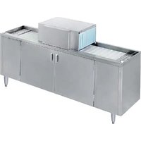
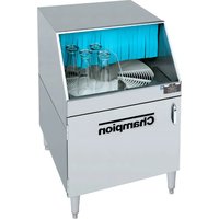
CG6 - Dishwasher Champion - Free user manual and instructions
Find the device manual for free CG6 Champion in PDF.


| Product Type | Dishwasher |
| Brand | Champion |
| Model | CG6 |
| Installation Type | Built-in / Integrated |
| Dimensions (H x W x D) | 81.5 x 59.8 x 55.5 cm |
| Weight | 45 kg |
| Power Supply | 220-240 V, 50 Hz, 10 A |
| Energy Consumption | 0.95 kWh per cycle |
| Water Consumption | 9.5 L per cycle |
| Number of Place Settings | 12 |
| Number of Programs | 5 |
| Programs | Intensive, Eco, Quick, Glass, Rinse |
| Noise Level | 47 dB(A) |
| Control Type | Electronic buttons with display |
| Safety Features | Child lock, overflow protection, aquastop |
| Maintenance | Clean filters, rinse aid refill, salt refill |
| Repairability Index | 7.5 / 10 |
| Spare Parts Availability | Available for 10 years |
| Included Accessories | Salt funnel, rinse aid cap, instruction manual |
Frequently Asked Questions - CG6 Champion
User questions about CG6 Champion
0 question about this device. Answer the ones you know or ask your own.
Ask a new question about this device
Download the instructions for your Dishwasher in PDF format for free! Find your manual CG6 - Champion and take your electronic device back in hand. On this page are published all the documents necessary for the use of your device. CG6 by Champion.
USER MANUAL CG6 Champion
The Dishwashing Machine Specialists
Technical Manual

Pass-Through
Glasswasher
Model
CG4
CG6
Machine Serial No.
June, 2001
Manual P/N 111557 REV. E
Complete the information below so it will be available for quick reference.
Model Number ____ Serial Number ____
Voltage and Phase ____
Champion Parts Distributor ____ Phone ____
Champion Service Agency ____ Phone ____
Champion Industries Service: 1-800-858-4477 Champion Service Fax: 1-336-661-1660
We strongly recommend that you Fax your orders.
NOTE: When calling to order parts, be sure to have the model number, serial number, voltage, and phase of your machine.
Revision History
Revision Revised Serial Number Comments Date Pages Effectivity
| 02/18/91 All 5181 Issued manual and service parts list, Revision A |
| 10/12/94 4 6106 Tank switch shuts down machine, revised the schematic |
| 05/10/95 4 6216 Changed to new style chemical injection board, revised the schematic |
| 06/07/95 — 6226 Changed to narrow control box, eliminated float rod bearing |
| 02/02/97 All — Reissue of manual and service parts lists, Revision B |
| 02/28/00 43 — Revised wash down Hose Assy. Parts List |
| 06/18/00 38-39 G2182 Revised vacuum breaker part nos. |
| 06/18/01 43 — Added panels to optional accessories |
CONTENTS
Page
WARRANTY 4
INTRODUCTION.... 5
INSTALLATION.... 6
Unpacking 6
Measurements 7
Utility Locations 7
Electrical Connections.... 8
Plumbing Connections.... 8
Water Connections.... 8
Drain Connections 8
OPERATION....9
General 9
To Fill The Wash Tank 9
Operating Instructions 9
Approximate Chemical Settings.... 10
Plumbing Diagram.... 12
MAINTENANCE.... 13
Daily Cleaning Instructions.... 13
Weekly Cleaning Instructions.... 13
TROUBLESHOOTING.... 14
REPLACEMENT PARTS.... 17
ELECTRICAL SCHEMATICS 44
LIST OF FIGURES
Page
Figure 1 — Unpacking Parts.... 6
Figure 2 — Machine Measurements 7
Figure 3 — Wash Tank.... 9
Figure 4 — Plumbing Diagram.... 12
Figure 5 — Main Frame Assembly.... 18
Figure 6 — Spray Assembly 20
Figure 7 — Main Tank Assembly 22
Figure 8 — Lift Bracket and Drive Assembly .... 24
Figure 9 — Hood Assembly 26
Figure 10 — Control Box 28
Figure 11 — Control Box Cover/Chemical Injector Board.... 30
Figure 12 — Detergent Tank 32
Figure 13 — Inlet Plumbing.... 34
Figure 14 — Sanitizer Plumbing.... 36
Figure 15 — Vacuum Breaker Plumbing 38
Figure 16 — Wash Pump Assembly 40
Figure 17 — Cleaning Accessories 42
Figure 18 — Optional Accessories .... 43
Figure 19 — Electrical Diagram (S/N 5181 through 6105).... 44
Figure 20 — Electrical Diagram (S/N 6106 through 6215).... 45
Figure 21 — Electrical Diagram (beginning with S/N 6216).... 46
LIMITED WARRANTY
Champion Industries Inc. (herein referred to as Champion), P.O. Box 4149, Winston-Salem, North Carolina 27115, and P.O. Box 301, 2674 N. Service Road, Jordan Station, Canada LOR 1S0, warrants machines, and parts, as set out below.
Warranty of Machines: Champion warrants all new machines of its manufacture bearing the name
“Champion” and installed within the United States and Canada to be free from defects in material and workmanship for a period of one (1) year after the date of installation or fifteen (15) months after the date of shipment by Champion, whichever occurs first. [See below for special provisions relating to glasswashers.] The warranty registration card must be returned to Champion within ten (10) days after installation. If warranty card is not returned to Champion within such period, the warranty will expire after one year from the date of shipment.
Champion will not assume any responsibility for extra costs for installation in any area where there are jurisdictional problems with local trades or unions.
If a defect in workmanship or material is found to exist within the warranty period, Champion, at its election, will either repair or replace the defective machine or accept return of the machine for full credit; provided, however, as to glasswashers, Champion's obligation with respect to labor associated with any repairs shall end (a) 120 days after shipment, or (b) 90 days after installation, whichever occurs first. In the event that Champion elects to repair, the labor and work to be performed in connection with the warranty shall be done during regular working hours by a Champion authorized service technician. Defective parts become the property of Champion. Use of replacement parts not authorized by Champion will relieve Champion of all further liability in connection with its warranty. In no event will Champion's warranty obligation exceed Champion's charge for the machine. The following are not covered by Champion's warranty:
a. Lighting of gas pilots or burners.
b. Cleaning of gas lines.
c. Replacement of fuses or resetting of overload breakers.
d. Adjustment of thermostats.
e. Adjustment of clutches.
f. Opening or closing of utility supply valves or switching of electrical supply current.
g. Cleaning of valves, strainers, screens, nozzles, or spray pipes.
h. Performance of regular maintenance and cleaning as outlined in operator's guide.
i. Damages resulting from water conditions, accidents, alterations, improper use, abuse, tampering, improper installation, or failure to follow maintenance and operation procedures. j. Wear on Pulper cutter blocks, pulse vanes, and auger brush.
Examples of the defects not covered by warranty include, but are not limited to: (1) Damage to the exterior or interior finish as a result of the above, (2) Use with utility service other than that designated on the rating plate, (3) Improper connection to utility service, (4) Inadequate or excessive water pressure, (5) Corrosion from chemicals dispensed in excess of recommended concentrations, (6) Failure of electrical components due to connection of chemical dispensing equipment installed by others, (7) Leaks or damage resulting from such leaks caused by the installer, including those at machine table connections or by connection of chemical dispensing equipment installed by others, (8) Failure to comply with local building codes, (9) Damage caused by labor dispute.
Warranty of Parts: Champion warrants all new machine parts produced or authorized by Champion to be free from defects in material and workmanship for a period of 90 days from date of invoice. If any defect in material and workmanship is found to exist within the warranty period Champion will replace the defective part without charge.
DISCLAIMER OF WARRANTIES AND LIMITATIONS OF LIABILITY. CHAMPION'S WARRANTY IS ONLY TO THE EXTENT REFLECTED ABOVE. CHAMPION MAKES NO OTHER WARRANTIES, EXPRESS OR IMPLIED, INCLUDING, BUT NOT LIMITED, TO ANY WARRANTY OF MERCHANTABILITY, OR FITNESS OF PURPOSE. CHAMPION SHALL NOT BE LIABLE FOR INCIDENTAL OR CONSEQUENTIAL DAMAGES. THE REMEDIES SET OUT ABOVE ARE THE EXCLUSIVE REMEDIES FOR ANY DEFECTS FOUND TO EXIST IN CHAMPION DISHWASHING MACHINES AND CHAMPION PARTS, AND ALL OTHER REMEDIES ARE EXCLUDED, INCLUDING ANY LIABILITY FOR INCIDENTALS OR CONSEQUENTIAL DAMAGES.
Champion does not authorize any other person, including persons who deal in Champion dishwashing
INTRODUCTION
Welcome to Champion...
and thank you for allowing us to take care of your glass washing needs.
This manual covers the Models CG4 and CG6 glasswashers.
Your machine was completely assembled, inspected, and thoroughly tested at our factory before it was shipped to your installation site.
This manual contains:
- Warranty Information
• Operation and Cleaning Instructions - Maintenance Instructions
- Troubleshooting Guide
- Basic Service Information
- Replacement Parts Lists
• Electrical Schematics
Complete and return your warranty registration card within ten (10) days after the installation of your machine.
All information, illustrations and specifications contained in this manual are based upon the latest product information available at the time of publication. Champion constantly improves its products and reserves the right to make changes at any time or to change specifications or design without notice and without incurring obligation.
For your protection, factory authorized parts should always be used for repairs.
Replacement parts may be ordered directly from Champion authorized parts distributor or authorized service agency. When ordering parts, please supply the model number, serial number, voltage, and phase of your machine, the part number, part description and quantity.
INSTALLATION
Unpacking
- Remove all packing from inside and on top of the machine.
- Remove all packing from glass operated switch and left and right pick-up plates. Check that the left and right hand pick-up plates are positioned properly.
- Check the position of the splash curtains.
- Check that the conveyor is aligned with the drive sprockets and the lift bracket on the right hand side is firmly engaged over track adjusters.
- Remove the packing from within and above the detergent tank.
- Ensure the standpipe is in position in the detergent tank. Ensure the short standpipe is in position on the right hand side of the wash tank underneath the conveyor lift bracket.

NOTE:
The wash tank standpipe is located inside the wash return screen for shipping.
- Ensure that the wash return screen in the detergent tank is in position.
- Check that the lower drain screen is in position.

Figure 1 — Unpacking Parts
INSTALLATION (Cont'd)
Measurements
| Uncrated CratedSW-400 SW-600 SW-400 SW-600 | ||||
| Height 38 | -1/2" (978) 38-1/2" | (978) 49" (1244) | 46-1/2" (1181) | |
| Width 48 | "(1219) 72" (1182) | 25-1/4" (640) 27" | (685) | |
| Depth 22 | "(559) 22" (559) | 25-1/8" (638) | 27-1/2" (698) | |
| Ship Wt. | 225lb/102kg | 285lb/129kg | 154lb/70kg | 176lb/80kg |
*adjustable foot height 1-3/4" (45)
max. height 40-3/4" (1035)
![SW400 6' [1829] ELECTRIC WITH PLU 19" [483] -24" [610] 22" [559] 12" [305] 2 2" [57] 48" [1219] 12 2" [311] 6" [152] ① ②](/content/2026/07/1432254/images/c6d418c11190055cfeeaeedf9eda8fd82832f8023676e4677d4aa83b449195a6.jpg)
![SW600 CORD G 6" [1829] ELECTRIC CORD WITH PLUG 31" [787] 36" [914] 3 22" [559] 12" [305] 14½" [362] 12½" [311] 6" [152] 72" [1829] ① ②](/content/2026/07/1432254/images/89841026e163020f60db2658121819d077efc07fc849f83828aaee7ac72f82a3.jpg)
![Plan View 10 ½" [261] VERTICAL CLEARANCE 9 ½" [235] 23 ½" [591] 38 ½" [978] 6" [152] 6" [152] 48" [1219]](/content/2026/07/1432254/images/89e06d023f0deee7fcfb218c8ec2820a88411d5db3d1470d9e5b083f6f886cdb.jpg)
Front View
![Plan View 10½" [261] VERTICAL CLEARANCE 9½" [235] 23½" [591] 6" [152] 72" [1829] 38½" [978] 6" [152]](/content/2026/07/1432254/images/6a38056896986a8aa3f251a6ec4525af9e43d241383a0997b67a29d5a1fc71cc.jpg)
DIMENSIONS SHOWN IN
INCHES AND MILLIMETERS
Front View
Figure 2 — Machine Measurements
Utility Locations
- Hot Water
- Cold Water
- Drain

CAUTION:
Allow 2" (50mm) additional vertical clearance above hood to permit hood removal when installing unit under a counter top.
INSTALLATION (Cont'd)
Electrical Connections
- The Glass Washer has a six foot power cord with a "U" ground tandem plug for connection to a power receptacle.
- Provide a nonlocking 250 volt, 15 ampere, 2 pole, 3 wire grounding receptacle within four feet of the base of the Glass Washer(CSA TYPE 6-15R). This should be installed by a qualified electrician to meet the specifications of the local electrical code.
- This machine operates from 208 to 240 volts.

NOTE:
This machine is 50Hz and 60Hz capatable.
Plumbing Connections
Hot Water Connection
- Connect a minimum 1/2" water line to the hot water solenoid valve. Supply temperature must be minimum 140°F/60°C, with a flow pressure between 25-95 PSI/172-656 kPa.
- Hot water consumption is approximately 10 Imp. gph./12 U.S. gph/45 litres/h.
Cold Water Connection
- Connect a minimum 1/2" water line to the cold water solenoid valve. Flow pressure must be between 25-95 PSI/172-656 kPa.
- Open mixing valve located between hot and cold solenoid valves for areas with very cold rinse water to heat the rinse water which will prevent glasses from cracking.
- Cold water consumption is approximately 2.4 Imp. gpm/2.8 U.S. gpm/10.6 litres/min.

NOTE:
Install check valves on the hot and cold water lines as close as possible to the water inlet.
Drain Connection
- This machine is gravity drain. Connect a 1-1/2" drain line where indicated.
- PVC pipe is generally recommended as copper is prone to attack by the sanitizing chemicals.

WARNING:
Plumbing and electrical connections should be made by a qualified workman who will observe all the applicable plumbing, sanitary and safety codes. Before all utilities are installed, ensure that all the bullet feet are in contact with the floor and at the desired level.
OPERATION
General
- The wash tank is equipped with a float assembly that operates a single cam-operated switch.
- The water temperature is controlled by a heater and a thermostat. The thermostat should be between 140°F/60°C and 160°F/71°C.
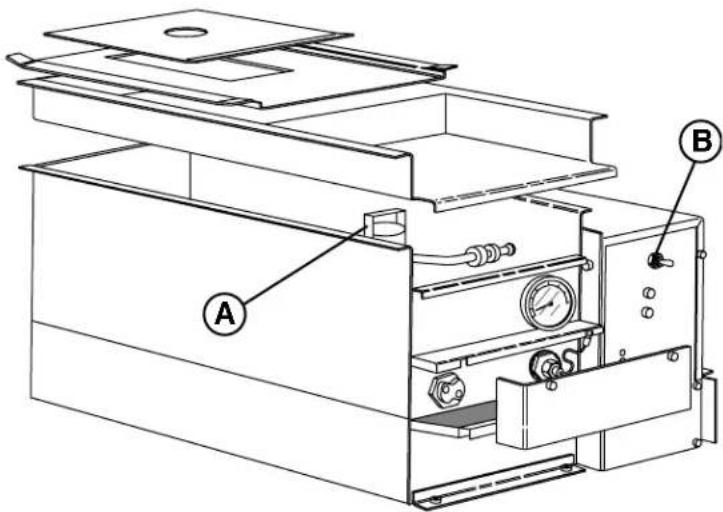
Figure 3 — Wash Tank
To Fill the Wash Tank
Ensure that the standpipe (A) is in place. Put switch (B) up to the “ON-FILL” position. The water will fill until the proper level is reached. The heating element will then turn on automatically once the tank has filled.
Detergent is fed from the supply container into the detergent tank in controlled amounts by the detergent pump. Use detergent at a strength of 0.35% or as recommended by your chemical supplier.
To Flush the Wash Tank
The selector switch (B) may be pushed down to the “FLUSH” position to clean the detergent tank during cleaning operations. The glasswasher will not wash dishes in the flush position. To use the flush function: Remove the standpipe (A) and drain the tank. Push the selector switch (B) down to the flush position. Water will enter the detergent tank as long as the switch is held in the “FLUSH” position. When desired flushing is complete, release switch (B).

NOTE:
Use a commercial grade NON-CHLORINATED liquid detergent manufactured specifically for glassware washing machines. Your chemical representative should test the solution to ensure the proper strength to achieve the best cleaning results.

NOTE:
Many of the chemicals used in glass and dishwashers are harmful to the skin and eyes in their concentrated form. Use extreme caution when handling containers to prevent accidental exposure.
Operating Instructions
- Open front door, flip toggle switch located on wash tank to the "ON-FILL" position. Wash tank will automatically fill.
- Ensure there is product in the detergent, sanitizer and rinse agent containers.
- Load glasses on the conveyor. Start machine with round start/stop knob located on the front load side of unit. Machine will now stop with shut-off rod and can be restarted with the round stop/start knob or shut-off rod.
OPERATION (Cont'd)
APPROXIMATE CHEMICAL SETTINGS
General
Approximate chemical settings can be obtained by counting the revolutions of the injector rotors.
- For detergent, one revolution per second equals approximately 0.35% concentration.

NOTE:
Detergent pump only operates when hot water tank is filling.
- For sanitizer, one revolution in 5 seconds equals approximately 12.5 ppm lodine or 50 ppm chlorine.
- For rinse agent, one revolution in 8 seconds is recommended.
To Adjust Detergent Injector:
- When a new detergent container is installed, push the prime button in and hold until the detergent feed tube is full.
- Install the detergent tank standpipe and switch tank fill toggle switch up to the "ON-FILL" position. The detergent feeder will now feed detergent into the detergent tank with water fill.
- To increase detergent volume, turn the detergent adjustment screw clockwise.
- To decrease the detergent volume, turn the detergent adjustment screw counter-clockwise.
To Adjust Sanitizer Injector:
- When a new sanitizer container is installed, push the prime button in and hold until sanitizer feed tube is full.
- Start the washer with rocker switch located on the front of the machine. Take a sample from the final rinse spray tube to check sanitizer level.
- To increase the volume of sanitizer, turn the adjustment screw clockwise.
- To decrease the volume of sanitizer, turn the adjustment screw counter-clockwise.

NOTE:
If Iodopher is being used as a sanitizer, it is not necessary to use a separate rinse agent. To turn rinse agent injector “OFF” in this case, turn the adjustment screw counter-clockwise until the pump stops turning.

NOTE:
OPERATION (Cont'd)
To Adjust Rinse Agent Injector:
- When a new rinse agent container is installed, push the prime button in and hold until the rinse injector feed tube is full.
- Start the washer. Take a sample from the final rinse spray tubes.
- To increase the volume of rinse agent, turn the adjustment screw clockwise.
- To decrease the volume of rinse agent, turn the adjustment screw counter-clockwise.

NOTE:
To meet the requirements of N.S.F. standards, Iodophor in a concentration of 12.5 ppm or chlorine at 50 ppm must be used in the final rinse.
OPERATION (Cont'd)
![graph TD A["WASH"] --> B["RINSE"] B --> C["1"] C --> D["2"] D --> E["3"] E --> F["4"] F --> G["5"] G --> H["6"] H --> I["TO DRAIN"] J["WASH WATER TANK"] --> K["7"] K --> L["MAIN TANK STANDPIPE"] K --> M["CHEMICAL INJECTOR"] K --> N["INJECTION FITTING"] K --> O["WATER INLET VALVES"] K --> P["MIXING V…](/content/2026/07/1432254/images/2ec2882d12fb2926670e6b6ae60054de29ce1383e1ac13ee0fd7541f215ea8ad.jpg)
Figure 4 — Plumbing Diagram
MAINTENANCE
CLEANING
Daily Cleaning Instructions
- Clear the conveyor of glassware and turn glasswasher off by flipping the toggle switch located on the wash tank to the "off" position.
- Remove load and unload end pick-up plates and splash curtains. Wash them with hot soapy water, rinse thoroughly, then dry.
- Lift and remove spray hood and set it aside.
- At right hand side of machine, raise conveyor lift bracket to stop position. Remove any debris from catch pan located below spray tubes and in area surrounding overflow tube.
- Remove overflow tube at right side of upper tank area. Starting at the left side of the machine, flush all debris from left to right side of machine using a wash down nozzle.

NOTE:
Do not leave water in tank overnight!!!
- Replace overflow tube, lower lift bracket to adjusters and ensure brackets are solidly engaged over track adjusters.
- Replace spray hood, ensuring hood hose connections are firmly engaged. Replace curtains and pick-up plates.
- Remove and clean upper and lower wash tank screens. Remove standpipe from the detergent tank; wash down then rinse the interior of the detergent tank.
- Replace stand pipe. Replace both upper and lower screens.
- Ensure there is product in the detergent, sanitizer and rinse agent containers. Close doors.
Weekly Cleaning Instructions
- Lift and remove front spray-hood cover and open front doors. Remove upper and lower manifold end caps and clean spray tubes with reamer, tube brush, and tube scraper provided.
- Remove detergent, sanitizer, and rinse agent feed lines from containers and place them in a container of hot water. Hold prime buttons in until the feed lines have been thoroughly flushed. Replace the feed lines to their proper container and prime product through lines.
TROUBLESHOOTING
CONDITION CAUSE SOLUTION
| Conveyor does not turn No power......Check fuse panelTurn power switch onDrive motor burnt out ......ReplaceObstruction in wash or rinse ......Remove obstructionMicro-switch on switch support......Adjust or replacebracket faulty or not makingcontactConveyor not in position......Position properlyConveyor tension too loose......Adjust tension with track adjustersConveyor catching on spray......Ensure spray tube retaining clips are intube support positionDrive sprocket slipping ......Tighten set screwDrive chain too slack ......Adjust tensionDrive chain seized or broken ......Lubricate or replace | |
| Excessive overspray Splash curtain not in position ......Install or adjustfrom hood section Washer running without any......Keep conveyor loaded with glassesglasses on conveyorSpray tubes at wrong angle......Ensure spray tube ends arc in slotsprovided to ensure proper spray angleSpray tubes plugged......Clear and clean with reamer, scraper, andbrush | |
| Lack of pressure at wash No water in detergent tank......Ensure water supply is onspray tubes Ensure detergent tank stand pipe is in positionEnsure the tank fill switch is in “ON-FILL”position and that tank fills with waterEnsure the float switch is activated by the floatcamEnsure the tank fill solenoid valve isoperationalObstruction in wash arm ......Clear obstructionPump not operating ......Check power supply to machineCheck pump capacitorReplace pump if requiredPump operating but no pressure......Check condition of impeller and stub shaftReplace if neededPump supply line plugged......Clear line of cause | |
| Lack of pressure in rinse Rinse spray tubes dirty......Clean thoroughly with reamer, scraper, andspray tubes brush providedShut-off valve on supply......Open valveline closedLow water pressure ......Minimum 25PSI flow pressure requiredRinse solenoid valve will ......Check coilnot operate Check and install rebuild kitReplace if necessaryRinse solenoid valve strainer ......Remove screen and cleanplugged | |
| Water continues to flow to Solenoid valve not seating ......Clean seatdetergent tank or spray tubeswith machine off | Install diaphragm kitReplace valve |
CONDITION CAUSE SOLUTION
| Water temperature low Thermostat setting low......Adjust thermostat in detergent tank Thermostat defective......ReplaceDefective float switch ......ReplaceHeater burnt out ......Check and replaceEnsure water level is above elementIncoming water temp. low ......Hot water supply min. 145°F/66°C |
| Water on floor around Pump seal leaking ......Replace machine Rinse drain in wash area plugged ......Clear obstruction, clean machineWash return screen in detergent......Cleantank pluggedDrain screen under detergent ......Cleantank pluggedMain drain plugged ......CleanDetergent tank covers are not ......Position all top covers to completely cover positioned properly causing top of tank condensationFill chute has lime build-up ......De-scale detergent tankSpray tube clean out caps loose ......Tighten caps or o-rings damaged Replace o-rings |
| Chemical containers filling Dirty rinse tubes ......Refer to cleaning section with water Element tube worn ......ReplaceWorn flow washer in solenoid ......Replace valve |
| Chemicals not feeding No product in containers......Refill containerProduct gelling or crystallizing......Flush all lines with hot water and use fresh in chemical line supply of chemicalChemical supply strainer plugged......Clean with hot waterSpeed adjustment set too low......Increase by turning clockwise while machine is running/fillingNo power to pump ......Check power LED on chemical control boardCheck signal LED for detergent, sanitize/rinse on boardReplace board if necessaryPump motor defective ......Replace pump motorElement tube stretched ......Replace |
REPLACEMENT PARTS
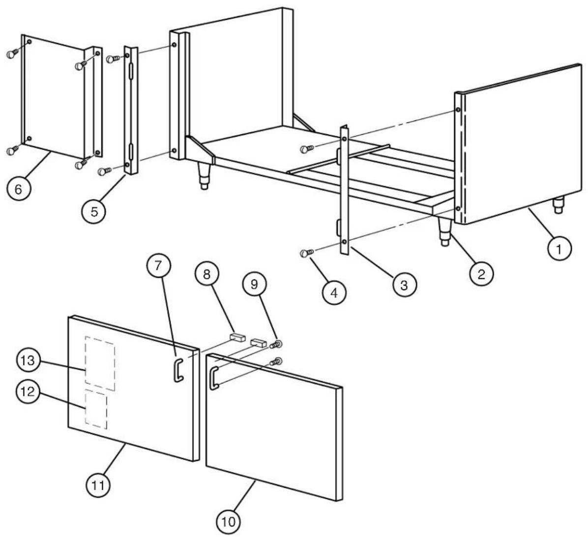
Figure 5 — Main Frame Assembly
MAIN FRAME ASSEMBLY
Fig. 5 Part Part Description Qty. Item No. No.
1 0707561 Frame Assembly, SW600.... 1
1 0707673 Frame Assembly, SW400.... 1
2 0501873 Grey Cast Foot 4
3 0703003 Hinge Rail, Right Side .... 1
4 0501412 Screw, 10-32 x 3/8"....8
5 0703002 Hinge Rail, Left Side .... 1
6 0308100 Front Side Panel, SW600 only....2
7 0501921 Door Handle 2
8 0501885 Magnetic Door Catch 2
9 0501464 Screw, 10-24 x 3/8"....4
10 0707514 Door Assembly, Right Hand .... 1
11 0707515 Door Assembly, Left Hand .... 1
12 0507836 Label, Wiring Schematic.... 1
13 0507582 Label, Cleaning .... 1

Figure 6 — Spray Assembly
SPRAY ASSEMBLY
Fig. 6 Part Part Description Qty. Item No. No.
| 1 | 0501746 Manifold Cap | 10 |
| 2 | 0501753 O-Ring | 10 |
| 3 | 0301790 Manifold, Triple | 2 |
| 4 | 0501745 O-Ring | 10 |
| 5 | 0503589 O-Ring | 10 |
| 6 | 0501716 Manifold Retaining Nut | 10 |
| 7 | 0307502 Manifold Plug | 1 |
| 8 | 0301795 Manifold, Double | 2 |
| 9 | 0303009 Retaining Rod, Triple | 2 |
| 10 | 0303010 Retaining Rod, Double | 2 |
| 11 | 0501718 Spray Tube, Rinse (14 Holes) | 2 |
| 12 | 0501719 Spray Tube, Rinse (13 Holes) | 2 |
| 13 | 0501717 Spray Tube, Wash | 5 |
| 14 | 0501407 Screw, 8-32 x 1/4" | 10 |
| 15 | 0501497 Washer, Lock | 10 |
| 16 | 0303091 Retainer, L.H. | 6 |
| 17 | 0303092 Retainer, R.H. | 4 |

Figure 7 — Main Tank Assembly (R-L Shown)
MAIN TANK ASSEMBLY
Fig. 7 Part Part Description Qty.
Item No. No.
| 1 | 0707562 | Main Tank, SW600 | 1 |
| 1 | 0707497 | Main Tank, SW400 | 1 |
| 2 | 0707498 | Main Tank Standpipe | 1 |
| 3 | 0303221 | Pick Up Plate, Load End | 1 |
| 4 | 0307500 | Wash Return Pan | 1 |
| 5 | 0303224 | Pick Up Plate, Slotted, Unload End | 1 |
| 6 | 0707485 | Shut-off Rod | 1 |
| 7 | 0501736 | Bushing, Shut-off Rod | 2 |
| 8 | 0501728 | Pivot Cap | 2 |
| 9 | 0501721 | Pivot, Activator Channel | 2 |
| 10 | 0302975 | Slide Washer | 2 |
| 11 | 0501727 | Activator Channel Guide | 2 |
| 12 | 0501408 | Screw, 8-32 x 1/4" | 4 |
| 13 | 0707576 | Activator Channel, SW600 | 1 |
| 13 | 0707503 | Activator Channel, SW400 | 1 |
| 14 | 0307518 | Retainer, for Pick-up Plate | 4 |
| 15 | 0501539 | Nut, 1/4-20 | 4 |
| 16 | 0501501 | Lock Washer, 1/4" | 4 |
| 17 | 0501412 | Screw, 10-32 x 3/8" | 4 |
| 18 | 0703080 | Disconnect Tube Assembly | 1 |
| 19 | 0504825 | Label, Rating | 1 |
| 20 | 0302970 | Door Catch Plate | 1 |
| 21 | 0507583 | Label, Caution | 1 |
| 22 | 0307489 | Switch Cover, SW600 | 1 |
| 22 | 0307488 | Switch and Chain Cover, SW400 | 1 |
| 23 | 0503301 | Label, (disconnect from supply) | 1 |
| 24 | 0503723 | Screw, 6-32 x 1" | 2 |
| 25 | 0501375 | Trip Switch | 1 |
| 26 | 0503574 | Strain Relief Bushing | 1 |
| 27 | 0307506 | Activating Switch Bracket | 1 |
| 28 | 0502977 | Dual Weld Nut, 6-32 | 1 |
| 29 | 107964 | Bushing, snap 1/2" | 2 |
| — | 0507493 | Insulation, tank (CG4) | 1 |
| — | 0507587 | Insulation, tank (CG6) | 2 |
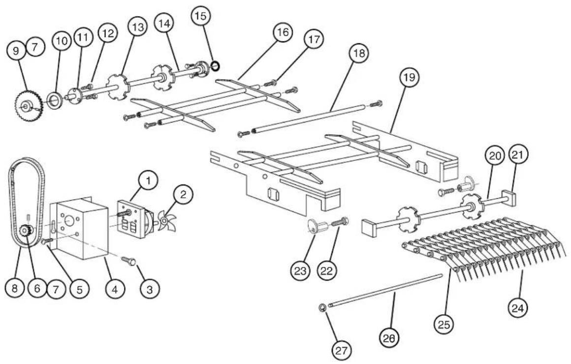
Figure 8 — Lift Bracket and Drive Assembly
LIFT BRACKET AND DRIVE ASSEMBLY
| Fig. 8 Part Item No. | No. | Part Description | Qty. |
| 1 | 0501345 Drive Motor, 230 Volt c/w Fan | 1 | |
| 2 | 0501355 Motor Fan, 2-5/8" Dia | 1 | |
| 3 | 0501456 Bolt, 1/4-20 x 1/2" | 3 | |
| 4 | 0702979 Motor Mount Assembly | 1 | |
| 5 | 0501408 Screw, 8-32 x 1/4" | 4 | |
| 6 | 0501793 Sprocket, 16 Tooth c/w Set Screw | 1 | |
| 7 | 0501395 Set Screw, 1/4-20 x 5/16" | 2 | |
| 8 | 0501899 Drive Chain | 1 | |
| 9 | 0501706 Sprocket, 54 Tooth c/w Set Screw | 1 | |
| 10 | 0501731 Spacer, Drive Shaft | 1 | |
| 11 | 0501729 Drive Shaft Bushing | 2 | |
| 12 | 0501419 Screw, 1/4-20 x 1/2" | 6 | |
| 13 | 0501710 Sprocket, Conveyor | 4 | |
| 14 | 0501732 Drive Shaft, 5/8" Dia | 1 | |
| 15 | 0501702 Retaining Ring | 1 | |
| 16 | 0704576 Slide Rail Assembly, SW600 | 1 | |
| 16 | 0703029 Slide Rail Assembly, SW400 | 1 | |
| 17 | 0501418 Screw, 1/4-20 x 1/2" | 6 | |
| 18 | 0501593 Cross Rod | 2 | |
| 19 | 0703213 Lift Bracket Assembly, SW600 | 1 | |
| 19 | 0703154 Lift Bracket Assembly, SW400 | 1 | |
| 20 | 0501733 Idler Shaft, 2 - 5/8" Dia | 1 | |
| 21 | 0501722 Bushing, Idler Shaft | 2 | |
| 22 | 0501420 Bolt, 1/4-20 x 1" | 2 | |
| 23 | 0701724 Cam, Belt Adjustment | 2 | |
| 24 | 0503401 Conveyor Belt, SW600 | 1 | |
| 24 | 0503705 Conveyor Belt, SW400 | 1 | |
| 25 | 0501590 Conveyor Belt Link, SW600 | 1596 | |
| 25 | 0501590 Conveyor Belt Link, SW400 | 1036 | |
| 26 | 0501589 Conveyor Rod, SW600 | 57 | |
| 26 | 0501589 Conveyor Rod, SW400 | 37 | |
| 27 | 0503664 Retaining Ring, SW600 | 114 | |
| 27 | 0503664 Retaining Ring, SW400 | 74 | |
| — | 0704862 Idler Shaft Assembly, (items 13, 20, 21) | 1 | |
| — | 0704863 Drive Shaft Assembly, (items 9 - 15) | 1 |
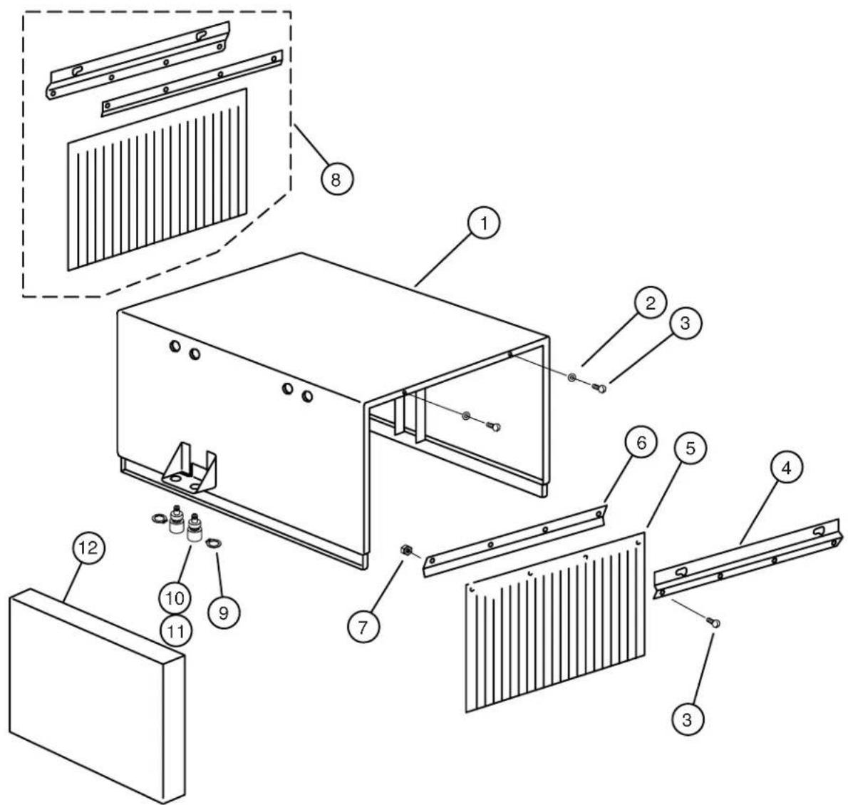
Figure 9 — Hood Assembly
HOOD ASSEMBLY
Fig. 9 Part Part Description Qty. Item No. No.
1 0703244 Hood, with vacuum breaker at rear.... 1
1 0708681 Hood, with vacuum breaker at front .... 1
2 0501497 Lock Washer, #8.... 4
3 0501408 Screw, 8-32 x 1/4".... 12
4 0302997 Curtain Bracket, Outer .... 2
5 0501743 Curtain....2
6 0302998 Curtain Bracket, Inner.... 2
7 0501538 Nut, 8-32 .... 4
8 0703176 Curtain Assembly Complete .... 2
9 0507011 Retaining Ring 2
10 0703702 Disconnect Assembly.... 2
11 0503703 O-Ring for Disconnect 2
12 0703078 Plumbing Cover .... 1

Figure 10 — Control Box
CONTROL BOX
Fig. 10 Part Part Description Qty. Item No. No.
| 1 0707403 Control Box (prior to S/N 6226)...... | 1 | |
| 1 0709049 Control Box (starting @ S/N 6226)...... | 1 | |
| 2 0307405 Injector Motor Plate...... | 1 | |
| 3 0501519 Tie, Nylon 4 in...... | 6 | |
| 4 0502666 Hose (1/8" I.D. x 1/4" O.D.)...... | AR | |
| 5 0706635 45CC Element Tube...... | 2 | |
| 6 0706634 15CC Element Tube...... | 1 | |
| 7 0707142 Rotor Assembly...... | 3 | |
| 8 0506589 Screw, 6-32 x 7/8"...... | 6 | |
| 9 0504822 Screw, 8-32 x 1/2"...... | 12 | |
| 10 0501353 Chemical Injector Motor...... | 3 | |
| 11 0507314 Start Capacitor (3 uF)...... | 1 | |
| 12 0307422 Thermostat Bracket...... | 1 | |
| 13 0501450 Screw, 6-32 x 3/16"...... | 4 | |
| 14 0507323 Thermostat...... | 1 | |
| 15 0503592 Label, Ground...... | 1 | |
| 15 0501403 Screw, Ground, 10-32 x 3/4"...... | 2 | |
| 15 0501533 Nut, Ground, 10-32...... | 2 | |
| 15 0501493 Washer, Lock, Ground, #10...... | 2 | |
| 15 0501472 Washer, Flat, Ground...... | 3 | |
| 16 0503648 Screw, 8-32 x 5/16"...... | 2 | |
| 17 0503647 Strain Relief Bushing (Medium)...... | 1 | |
| 18 0503574 Strain Relief Bushing (Small)...... | 2 | |
| 19 0501887 7/8" Button Plug...... | 1 | |
| 20 0507372 Power Cord...... | 1 | |
| 21 0503749 Terminal Board...... | 2 | |
| 22 0701933 Water/Heater Cam c/w Set Screw...... | 1 | |
| 23 0501397 Set Screw, 6-40 x 3/16"...... | 1 | |
| 24 0501379 Float Switch...... | 1 | |
| 25 0307369 Nut Plate for Float Switch (starting @ S/N 6226)...... | 1 | |
| 26 0501433 Screw, 4-40 x 5/8"...... | 2 | |
| 27 0501411 Screw, 10-32 x 1/4"...... | 8 | |
| 28 0309053 Float Switch Support (starting @ S/N 6226)...... | 1 | |
| 29 0503642 Label, 2.5 Amp Fuse...... | 1 | |
| 30 0503693 Label, Switch Up...... | 1 | |
| 31 0501373 3-Position Switch...... | 1 | |
| 32 0501412 Screw, 10-32 x 3/8"...... | 8 | |
| 33 0507470 Label, Injector Prime...... | 1 |
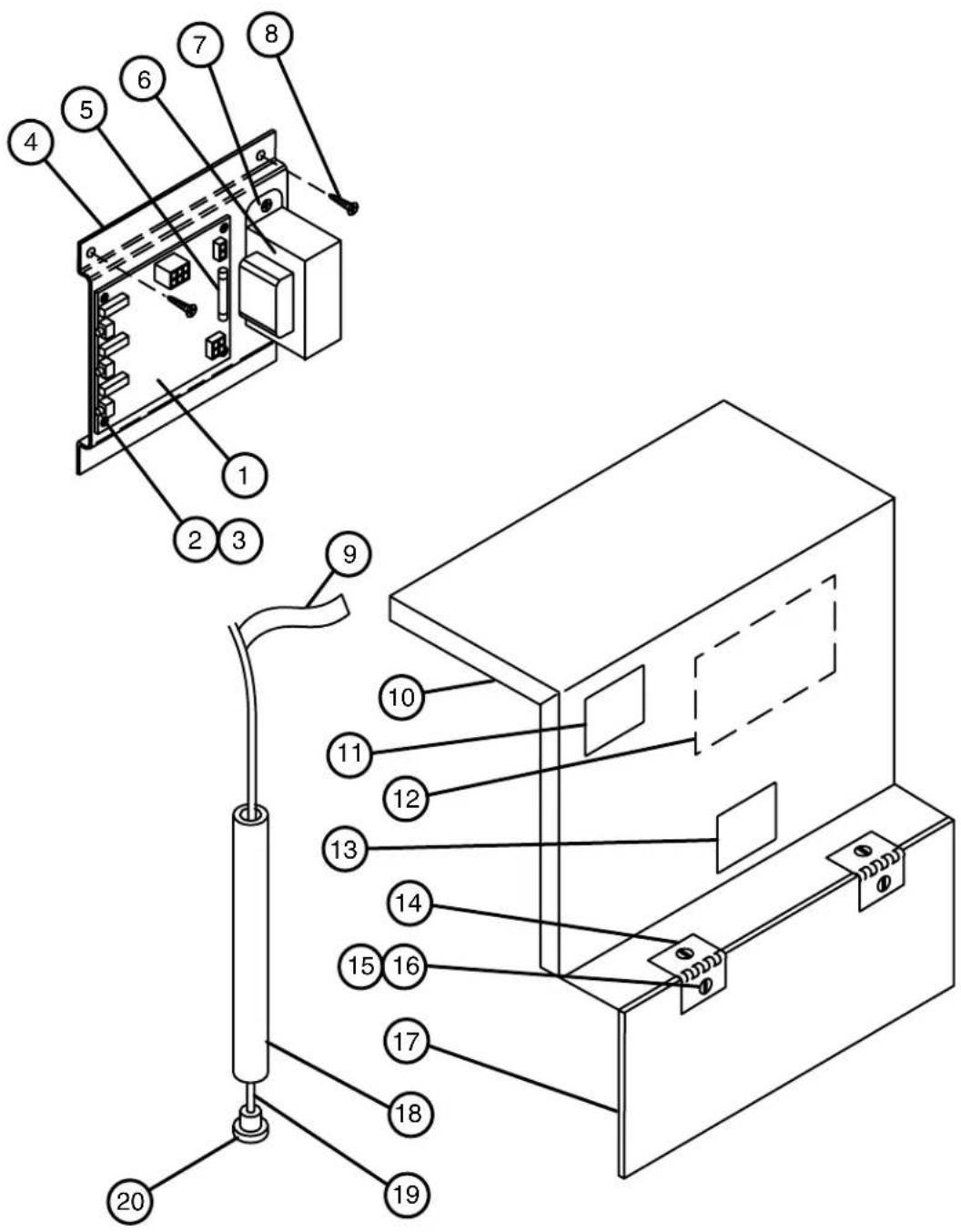
Figure 11 — Control Box Cover/Chemical Injector Board
CONTROL BOX COVER/CHEMICAL INJECTOR BOARD
Fig. 11 Part Part Description Qty.
| Item No. No. | |||
| 1 0508433 Circuit Board (starting @ S/N 6216)...... 1 | |||
| 2 106695 Screw, 6-32 x 1/2"...... 4 | |||
| 3 0508710 Spacer, 5/16 lg...... 4 | |||
| 4 0309037 Support Bracket (starting @ S/N 6216)...... 1 | |||
| 5 0503637 Fuse, 2.5 Amp ...... 1 | |||
| 6 0508920 Transformer (starting @ S/N 6216) ...... 1 | |||
| 7 0501450 Screw, 6-32 x 3/16"...... 4 | |||
| 8 0501411 Screw, 10-32 x 1/4"...... 2 | |||
| 9 0503695 Label, Detergent...... 1 | |||
| 9 0505483 Label, Rinse...... 1 | |||
| 9 0503694 Label, Sanitizer ...... 1 | |||
| 10 0307408 Control Box Cover (prior to S/N 6226)...... 1 | |||
| 10 0309052 Control Box Cover (starting @ S/N 6226) ...... 1 | |||
| 11 0503301 Label, Warning...... 1 | |||
| 12 0509061 Label, Circuit Board (starting @ S/N 6216)...... 1 | |||
| 13 0503343 Label, Warranty Void...... 1 | |||
| 14 0300986 Hinge, Cover ...... 2 | |||
| 15 0501408 Screw, 8-32 x 1/4"...... 4 | |||
| 16 0501538 Nut, 10-32 ...... 4 | |||
| 17 0307409 Injector Pump Cover ...... 1 | |||
| 18 0306363 Dip Tube...... 3 | |||
| 19 0502666 Hose, 1/8" I.D. x 1/4" O.D...... AR | |||
| 20 0501869 Strainer ...... 3 | |||
| NS 0507577 Wiring Harness (Drive Motor, Solenoid Valves)...... 1 | |||
| NS 0507578 Wiring Harness, Circuit Board (prior to S/N 6216) ...... 1 | |||
| NS 0509039 Wiring Harness, Circuit Board (starting @ S/N 6216)...... 1 | |||
| NS 0503739 Aluminum Spacer, Float Switch (prior to S/N 6226) ...... 2 |

NOTE:
The circuit board shown in this diagram started at S/N 6216. Prior units will require circuit board conversion kit P/N 0708523. Once this kit has been installed, all replacement parts except the wiring harness will be as shown. Replacement wiring harness for circuit board kit is P/N 0509038.

Figure 12 — Detergent Tank
DETERGENT TANK
Fig. 12 Part Part Description Qty. Item No. No.
| 1 0707415 Detergent Tank (up to S/N 6226)...... | 1 | |
| 1 0709054 Detergent Tank (starting @ S/N 6226)...... | 1 | |
| 2 0307296 Detergent Tank Cover Lid...... | 1 | |
| 3 0307378 Detergent Tank Rear Cover...... | 1 | |
| 4 0707375 Detergent Tank Screen Assembly...... | 1 | |
| 5 0507471 Label, Clean Screens Daily...... | 2 | |
| 6 0700948 Standpipe Assembly...... | 1 | |
| 7 0503670 Float Ball...... | 1 | |
| 8 0507426 Float Rod...... | 1 | |
| 9 0703673 Cam Bushing c/w Set Screw...... | 1 | |
| 10 0501397 Set Screw, 6-40 x 3/16"...... | 1 | |
| 11 0503701 Timer Shaft Bearing (not req'd after S/N 6226)...... | 2 | |
| 12 0504864 Label, Data...... | 1 | |
| 13 0501896 Thermometer Seal...... | 1 | |
| 14 0501600 8" Thermometer...... | 1 | |
| 15 0503588 Heater "O" Ring...... | 1 | |
| 16 0507315 3 KW Heater c/w "O" Ring...... | 1 | |
| 17 0507323 Thermostat (Capillary only shown)...... | 1 | |
| 18 0501650 Thermostat Adaptor...... | 1 | |
| 19 0501836 Adaptor "O" Ring...... | 1 | |
| 20 0501419 Bolt, 1/4-20 x 1/2"...... | 1 | |
| 21 0707383 Drain Pan Screen Assembly...... | 1 | |
| 22 0707380 Drain Pan Assembly...... | 1 | |
| 23 0307423 Heater Cover...... | 1 | |
| 24 0503301 Label, Warning...... | 1 | |
| 25 0501412 Screw, 10-32 x 3/8"...... | 2 | |
| 26 107435 Nut, M6...... | 4 | |
| 27 107886 Inlet Chute Gasket...... | 1 | |
| 28 108051 Elbow Flange...... | 1 | |
| 29 0507431 Bolt, M6 x 25mm...... | 4 | |
| 30 0502563 1" Gear Clamp...... | 1 | |
| 31 0502668 1" I.D. Braided Hose...... | AR | |
| 32 0307427 Inlet Water Tube...... | 1 | |
| 33 0503679 7/16" Gear Clamp...... | 2 | |
| 34 0502665 1/2" I.D. Braided Hose...... | 1 | |
| 35 0502662 1-1/2" Vac-U-Flex Hose...... | 23" | |
| 36 0502571 1-1/2" Clamp, Hose...... | 1 |

Figure 13 — Inlet Plumbing
INLET PLUMBING
Fig. 13 Part Part Description Qty.
Item No. No.
| 1 0502783 230V 60HZ Solenoid Valve | 2 | |
| 2 0503802 3/8" MPT Tee | 3 | |
| 3 0503801 3/8" Fem x 1/2" Fem Adapter | 2 | |
| 4 0507324 3/8" Check Valve | 1 | |
| 5 0502768 Mixing Valve | 1 | |
| 6 0502653 3/8" x 1/2" 90° Hose Barb | 2 | |
| 7 0503679 7/16" Gear Clamp | 2 | |
| 8 0502665 1/2" I.D. Braided Hose | AR | |
| 9 0509659 Brass Cap | 1 | |
| 10 0307688 Inlet Plumbing Clamp | 1 | |
| 11 0501419 Bolt, 1/4-20 x 1/2" | 2 | |
| 12 0504822 Screw, 8-32 x 1/2" | 2 | |
| 13 0306208 Cable Clamp Cover | 1 | |
| 14 0307373 Cable Clamp Assembly | 1 | |
| 15 0501404 Screw, 10-32 x 3/8", Brass | 2 | |
| 16 0501493 Lock Washer, #10 | 2 | |
| 17 0501533 Nut, 10-32, Brass | 2 | |
| 18 0505229 Solenoid Guide | 1 | |
| 19 0502811 Diaphragm Kit | AR | |
| 20 0502810 Flow Washer (2.6 GPM) | 1 | |
| 21 0502807 Washer, Brass | 1 | |
| 22 0502804 Washer, Brass | 1 | |
| 23 0502803 Screen | 1 | |
| 24 0501406 Screw, 8-32 x 1/2" | 2 | |
| 25 0502806 Coil -230V 60HZ | 1 |

Figure 14 — Sanitizer Plumbing
SANITIZER PLUMBING
Fig. 14 Part Part Description Qty.
| Item No. No. | ||
| 1 0503668 Thermometer | 1 | |
| 2 0502583 3/8" FPT Cross Connector | 1 | |
| 3 0502653 3/8" MPT x 1/2" 90° Hose Barb | 1 | |
| 4 0502645 1/8" Hose Barb | 2 | |
| 5 0502666 1/8" Hose | AR | |
| 6 0502665 1/2" I.D. Braided Hose | AR | |
| 7 0503679 7/16" Gear Clamp | 2 | |
| 8 0503669 Injector Barb Fitting | 1 | |
| 9 0502577 3/8 x 1/4 MPT Reducer Bushing | 1 | |
| 10 0502781 Needle Valve | 1 | |
| 11 0507100 0-30 PSI Pressure Gauge | 1 | |
| 12 0300918 Plumbing Clamp | 1 | |
| 13 0501501 Lock Washer, 1/4" | 2 | |
| 14 0501539 Nut, 1/4-20 | 2 |
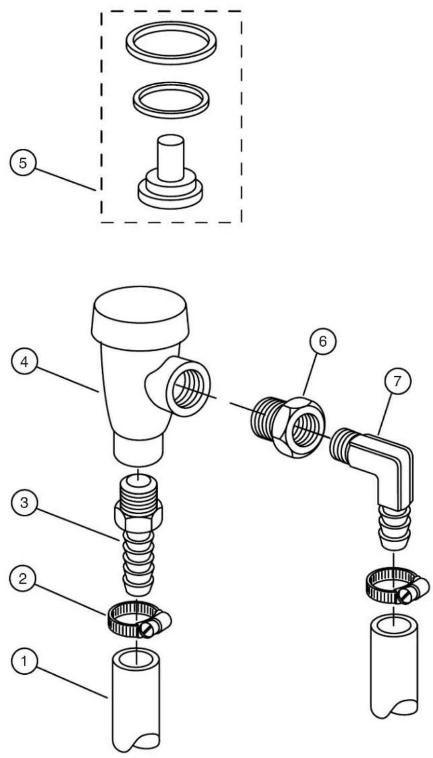
Figure 15 — Vacuum Breaker Plumbing
Fig. 15 Part Part Description Qty.
Item No. No.
| 1 0502665 1/2" x 3/4" Inner Braided Tubing ....... AR | |||
| 2 0503679 7/16" Gear Clamp ....... 2 | |||
| 3 0502651 1/2" MPT x 1/2" Hose Barb....... 1 | |||
| 4 0502751 1/2" Vacuum Breaker (Prior to S/N G2182)....... 1 | |||
| 5 0508366 Vac Breaker Kit (Prior to S/N G2182)....... AR | |||
| 6 0502650 1/2" x 3/8" Reducer Bushing ....... 1 | |||
| 7 | 0502653 | 3/8" MPT x 1/2" 90° Hose Barb....... | 1 |
| 8 | 113220 | 1/2" vacuum breaker ....... (Beginning with S/N G2182 and above) | 1 |
| 9 113221 Repair kit, vacuum breaker ....... 1(Beginning with S/N G2182 and above) | |||

NOTE:
Watts vacuum breaker repair kit is not available . . . use item #4.

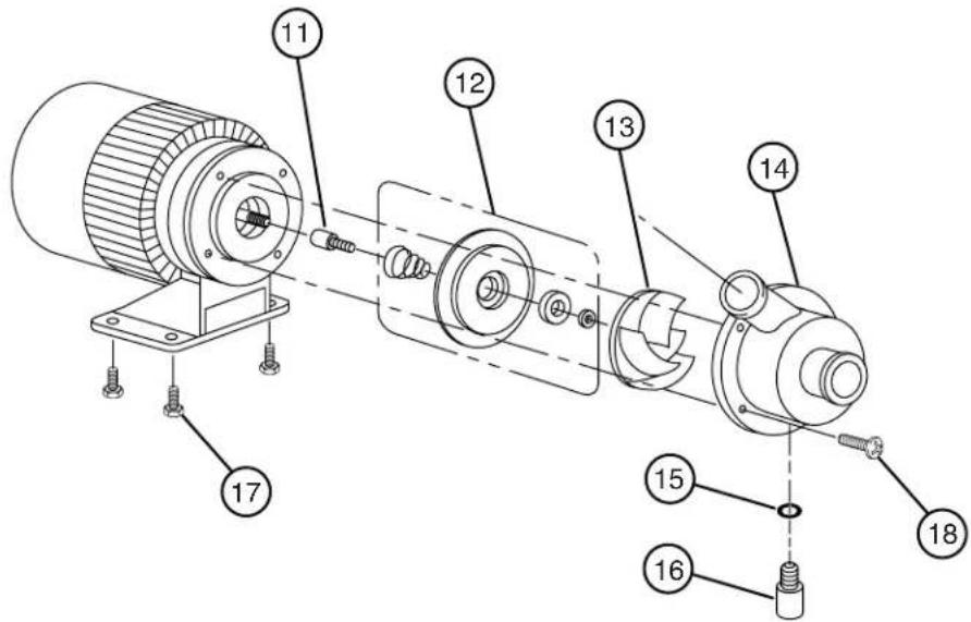
Figure 16 — Wash Pump Assembly
WASH PUMP ASSEMBLY
Fig. 16 Part Part Description Qty.
Item No. No.
1 0507313 Wash Pump Complete .... 1
2 0307410 Wash Pump Base.... 1
3 0501419 1/4-20 x 1/2" Bolt 2
4 0507320 1" I.D. X 1-1/4" O.D. PVC Hose...... AR
5 0502563 1" Gear Clamp....4
6 0502668 1" I.D. Braided Hose...... AR
7 0501632 Pump Hose Connector .... 1
8 0503679 7/16" Gear Clamp 2
9 0502665 1/2" I.D. Braided Hose...... AR
10 0502663 3/8" I.D. Braided Hose...... AR
11 0502734 Stub Shaft .... 1
12 0502730 Seal Kit c/w Spring AR
13 0502729 Impeller 1
14 0502731 Pump Housing.... 1
15 0501635 "O" Ring, 5/16 I.D. X 1/16W .... 1
16 0502732 Housing Seal Screw 1
17 0503648 Screw, 8-32 x 5/16"....4
18 0501406 Screw, 8-32 x 1/2"....4

NOTE:
Motor is not available as a separate item.

Figure 17 — Cleaning Accessories
CLEANING ACCESSORIES
Fig. 17 Part Part Description Qty.
Item No. No.
1 0703390 Tube Scraper .... 1
2 0501714 Tube Brush .... 1
3 0501633 Jet Reamer c/w Drill .... 1
4 0703454 Wash Down Nozzle....1
5 0505320 1/2" Hose Washer.... 1
6 0502779 Nozzle....1
7 0501833 1/2" x 10' Hose Assembly.... 1
8 0506643 Faucet .... 1
OPTIONAL ACCESSORIES (not shown)
Fig. 18 Part Part Description Qty.
Item No. No.
- 0706204 Drain Tray and Waste Collector
- 0707258 Quick Disconnect Package (Including Casters)
-0501874 Caster, reg.... 2 - 0501876 Caster, locking.... 2
- 0701962 Caster Kit (2 Locking, 2 Regular)
- 0507255 Hose, 1/2 female quick disconnect, 10'
- 0507256 Hose, 1/2 male quick disconnect, 16"
- 0708453 Hand Sink and Wet Waste Receiver (SW46)
- 0701956 Wash Down Hose (Includes Items 4 - 8)
- 0702882 Panel, Back CG4
- 0702886 Panel, Back CG6
![graph TD A["SW M5"] --> B["208/230V 12.8A 60HZ SINGLE PHASE"] B --> C["INJECTOR CONTROL BOARD"] C --> D["J1 1 DET PUMP"] C --> E["J2 1"] C --> F["WASH WATER VALVE"] C --> G["DET TANK HEATER"] C --> H["HEATER THERMOSTAT"] C --> I["TANK FILL TOGGLE SWITCH"] C --> J["FLUSH OFF AUTO"] C --> K["NO WATER…](/content/2026/07/1432254/images/5c9151c6becc168c887fce5317dac236d1941252475f80c349b147797c69ebe3.jpg)
Figure 19 - Electrical Diagram (S/N 5181 through 6105)
![graph TD A["SW M5"] --> B["208/230V 12.8A 60HZ SINGLE PHASE"] B --> C["INJECTOR CONTROL BOARD"] C --> D["J1 1 DET PUMP"] C --> E["J2 1"] C --> F["WASH WATER VALVE"] C --> G["DET TANK HEATER"] C --> H["HEATER THERMOSTAT"] C --> I["FLUSH"] C --> J["TANK FILL TOGGLE SWITCH"] C --> K["OFF"] C --> L["AUT…](/content/2026/07/1432254/images/f0038b0a2f36535b05347674c7a44914f7ab3f696c789d68b19a0a8b3e52bcc7.jpg)
Figure 20 - Electrical Diagram (S/N 6106 through 6215)
![graph TD A["GLASS SHUTOFF ARM SWITCH"] --> B["NO"] B --> C["NC"] C --> D["DIAGRAM IS FOR L-R OPERATION.<br>FOR R-L OPERATION USE N.O. TERMINAL."] D --> E["BLACK"] E --> F["RED"] F --> G["WASH PUMP MOTOR"] G --> H["WHITE"] G --> I["BLUE"] G --> J["GREEN"] G --> K["START CAPACITOR"] K --> L["240V PRIM…](/content/2026/07/1432254/images/6005bb01b1e4ae0ac431f23c2705f763448ba205b38e0748df6e918328671ca0.jpg)
Figure 21 - Electrical Diagram (beginning with S/N 6216)

- TECHNICAL MANUAL
- REVISION HISTORY
- CONTENTS
- LIST OF FIGURES
- LIMITED WARRANTY
- INTRODUCTION
- INSTALLATION
- UNPACKING
- NOTE
- INSTALLATION (CONT'D)
- UTILITY LOCATIONS
- CAUTION
- ELECTRICAL CONNECTIONS
- PLUMBING CONNECTIONS
- HOT WATER CONNECTION
- COLD WATER CONNECTION
- DRAIN CONNECTION
- WARNING
- OPERATION
- GENERAL
- TO FILL THE WASH TANK
- TO FLUSH THE WASH TANK
- OPERATING INSTRUCTIONS
- OPERATION (CONT'D)
- APPROXIMATE CHEMICAL SETTINGS
- TO ADJUST DETERGENT INJECTOR
- TO ADJUST SANITIZER INJECTOR
- TO ADJUST RINSE AGENT INJECTOR
- MAINTENANCE
- CLEANING
- DAILY CLEANING INSTRUCTIONS
- WEEKLY CLEANING INSTRUCTIONS
- TROUBLESHOOTING
- REPLACEMENT PARTS
- MAIN FRAME ASSEMBLY
- FIG. 5 PART PART DESCRIPTION QTY. ITEM NO. NO
- SPRAY ASSEMBLY
- MAIN TANK ASSEMBLY
- HOOD ASSEMBLY
- FIG. 9 PART PART DESCRIPTION QTY. ITEM NO. NO
- CONTROL BOX
- CONTROL BOX COVER/CHEMICAL INJECTOR BOARD
- DETERGENT TANK
- INLET PLUMBING
- SANITIZER PLUMBING
- WASH PUMP ASSEMBLY
- FIG. 16 PART PART DESCRIPTION QTY
- ITEM NO. NO
- CLEANING ACCESSORIES
- FIG. 17 PART PART DESCRIPTION QTY
- OPTIONAL ACCESSORIES (NOT SHOWN)
- FIG. 18 PART PART DESCRIPTION QTY
Brand : Champion
Model : CG6
Category : Dishwasher