Catapult Engineering - Educational toy Thames & Kosmos - Free user manual and instructions
Find the device manual for free Catapult Engineering Thames & Kosmos in PDF.


| Product Type | Construction Kit |
| Model | Catapult Engineering |
| Brand | Thames & Kosmos |
| Recommended Age | 8 years and up |
| Number of Pieces | Approximately 100 |
| Dimensions (Assembled Catapult) | 30 x 20 x 15 cm |
| Weight | 0.5 kg |
| Power Source | None (manual operation) |
| Main Functions | Build and experiment with catapult mechanisms; learn about force, trajectory, and physics |
| Number of Models | 5 different catapult designs |
| Material | Plastic, rubber bands, and metal rods |
| Assembly Required | Yes |
| Tools Included | No, but no special tools needed |
| Maintenance | Wipe with dry cloth; store in dry place |
| Safety Warnings | Not suitable for children under 3 years; small parts; projectile risk |
| Replaceable Parts | Rubber bands can be replaced |
| Repairability | Limited; contact manufacturer for missing parts |
| Manual Language | English |
| Manual Pages | 36 |
Frequently Asked Questions - Catapult Engineering Thames & Kosmos
User questions about Catapult Engineering Thames & Kosmos
0 question about this device. Answer the ones you know or ask your own.
Ask a new question about this device
Download the instructions for your Educational toy in PDF format for free! Find your manual Catapult Engineering - Thames & Kosmos and take your electronic device back in hand. On this page are published all the documents necessary for the use of your device. Catapult Engineering by Thames & Kosmos.
USER MANUAL Catapult Engineering Thames & Kosmos
Catapult Engineering
6-IN-1 MAKER KIT
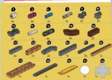
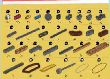
KIT CONTENTS

What's inside your experiment kit:


Catapult Engineering

CONTENTS
Kit Contents... Inside front cover
Table of Contents 1
Safety Information 2
Important Information 3
ASSEMBLY STARTS ON PAGE 6
Preparation 4
Knockdown Blocks.... 5
Model 1: Catapult .... 6
Model 2: Reverse-Draw Crossbow .... 10
Model 3: Onager 16
Model 4: Crossbow.... 20
Model 5: Trebuchet 25
Model 6: Ballista.... 28

TiP
ADDITIONAL EXPERIMENTS
CAN BE FOUND AT THE AND OF EACH MODEL
ND OF EACH MODEL ON PAGES 0, 15, 19, 24, 27 AND 30
7, 15, 17, 21, 27, AND 32.

Checklist:
√ No. Description Quantity Part No.
| ○ 1 Short anchor pin 5 7364-W10-C2W | ||
| ○ 2 Connector pin 12 1187-W10-E1K | ||
| ○ 3 Shaft plug 4 7026-W10-H1Y | ||
| ○ 4 Joint pin | 4 | 7413-W10-T1B |
| ○ 5 Long joint pin | 1 | 7413-W10-U1S |
| ○ 6 Large pulley wheel | 4 | 7344-W10-N351 |
| ○ 7 Small sprocket wheel | 1 | 3569-W10-D251 |
| ○ 9 Nose piece | 1 | 7402-W10-C2D |
| ○ 9 Two-to-one converter | 4 | 7861-W10-G153 |
| ○ 10 90-degree converter - X | 2 | 7061-W10-X153 |
| ○ 11 90-degree converter - Y | 2 | 7861-W10-Y153 |
| ○ 12 3-hole bolt rod | 2 | 7406-W10-B151 |
| ○ 13 Motor axle | 1 | 7926-W10-L1W |
| ○ 14 Axle, 30-mm | 1 | 7413-W10-N10 |
| ○ 15 100-mm axle | 1 | 7413-W10-L2D |
| ○ 16 Single passenger pin | 1 | 7402-W10-M16 |
J No.Description
Quantity Part No.
| ○21 | 5-hole red | 4 | 7013-W10-K2S2 |
| ○22 | 5-hole dual rod C | 3 | 7013-W10-X1T |
| ○23 | 5-hole L rod | 2 | 7406-W10-B2S1 |
| ○24 | 7-hole wide rounded rod | 1 | 7404-W10-C2S3 |
| ○25 | 7-hole flat rounded rod | 3 | 7404-W10-D3S3 |
| ○26 | 11-hole rod | 1 | 7413-W10-P1T1 |
| ○27 | 13x3 Frame | 2 | 7404-W10-A1T |
| ○28 | Long rack gear | 1 | 7401-W10-T2S |
| ○29 | Curved frame | 2 | 73P2-W10-III |
| ○30 | Anchor pin lever | 1 | 7401-W10-B1Y |
| ○31 | Large foam ball | 1 | K30#7366-2 |
| ○32 | Crossbow bolt | 2 | 7406-W85-A-US |
| ○33 | Rubber band, smell | 1 | R10-02 |
| ○34 | Rubber band, large | 1 | R10-2B |
| ○35 | 500-mm string | 1 | R39#7063 |
| ○36 | Pin screw, square nut | 1 | 617#7201 |
SAFETY INFORMATION


WARNING!
Not suitable for children under 3 years. Choking hazard — small ports and small balls may be swallowed or inhaled. Strangulation hazard — long string and long rubber bands may become wrapped around the neck. Keep the packaging and instructions as they contain important information.
WARNING! Do not aim at eyes or face.
Do not aim the projectiles (crossbow bolts and foam balls) toward other people or animals. Make sure people and animals are well out of the potential path of the projectiles.
WARNING! Do not discharge an object other than the projectiles
included with this kit.

Dear Explorers,
Please read these notes carefully. This information will help you avoid possible risks and get the most out of this experiment kit.


ANCHOR PINS AND CONNECTORS
TAKE A CAREFUL LOOK AT THE DIFFERENT ASSEMBLY COMPONENTS. WHITE ANCHOR PINS, PINK CONNECTOR PINS, YELLOW SHAFT PLUGS, AND BLUE JOINT PINS ALL LOOK PRETTY SIMILAR AT FIRST GLANCE, WHEN YOU ASSEMBLE THE MODELS, IT'S IMPORTANT TO USE THE RIGHT ONES.

AXLES
THE BUILDING SYSTEM CONTAINS AXLES (ALSO CALLED SHAFTS) OF VARIOUS LENGTHS. WHEN ASSEMBLING THE MODEL, ALWAYS BE SURE THAT YOU'RE USING THE RIGHT ONE.
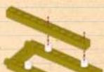
PULLEYS AND RATCHETS
IF PULLEYS OR RATCHETS ARE MOUNTED TOO TIGHTLY AGAINST OTHER COMPONENTS, THEY CAN BE HARD TO TURN. IF YOU LEAVE A GAP OF ABOUT 1 MM BETWEEN THE RATCHET OR PULLEY AND AN ADJACENT COMPONENT, IT WILL TURN EASILY.
IMPORTANT INFORMATION
Dear parents and adults,
Children want to explore, understand, and create new things. They want to try new things and they want to do this on their own. They want to gain knowledge! They can do all of this with Thames & Kosmos experiment kits. With every single experiment, they grow smarter and more knowledgeable.
— Physics is an exciting and varied science that is not hard to understand, especially when you use fun models to demonstrate physics principles in action. It can be a lot of fun to figure out the astonishing physical phenomena that we encounter every day and to put this understanding to use.
— This experiment kit and the working models you can build with it introduce your child to physics concepts including energy, motion, and forces. With its wealth of simple examples, your child will gain basic insights into the world of physical units and laws — which will help them to understand and engage more deeply in the lessons taught in school.
— The individual experimental models are assembled step by step using an adjustable building system. It will require a little practice and patience at first. And your child will be particularly happy to have your help with the models that they find more difficult.
— Some of the experiments will require common items from your household, including a dish, tape, measuring stick, coins, tissue, paper clips, and a stopwatch. Help your child select these items.
We hope you and your child have a lot of fun with Catapult Engineering!
PREPARATION
You will need
Metal pie pan or other durable dish, tape, measuring stick or tape measure
Here's how
- Place a metal pie pan upside down on the floor. This is your bull's eye target.
- Place a piece of tape 10 or so feet away from the pie pan. This is where you will stand when testing out your catapults and crossbows.

WHAT'S HAPPENING?
When you do the experiments with your catapults, you should think about the accuracy and precision of where the projectiles land. Accuracy is how close your results (or shots) are to your target value — in this case, the center of the target. Precision is how often you are able to get the same value, or have your projectile land in the same place. Look at the pictures to the right to see how accuracy and precision are related. Accuracy and precision are both critical concepts in the scientific world.
As you perform the experiments for each model, think about how the changes affect your precision and accuracy. Keep a record of your results for the different

Low accuracy and low precision

Low accuracy and high precision

High accuracy and low precision

Catapult Engineering

Knockdown Blocks
Your kit includes 16 knockdown blocks for you to build, stack, and knock over with the included projectiles.
Here's how
- Turn over the die-cut sheet so you see the white side. Fold the two A flaps upward toward the middle.
- Fold all four B flaps inward.
- Fold the two C flaps upward.
- Fold down the two D flaps 90 degrees so they are perpendicular to the C flaps.
- Fold down F and then fold over E so that E covers the box and F tucks inside.
- Push tab G into the slit.


Castle Walls
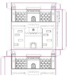
There are illustrations of castle walls on the inside of the Catapult Engineering box. You can use these as targets for the included projectiles.
Here's how
- Open up the box along the vertical seam.
- Have an adult carefully cut out the castle walls.
- Personalize the castle walls by coloring them in or adding other decorations.
MODEL 1: CATAPULT

The term catapult comes
from the Ancient Greek word
Katapeltes. The Ancient
Greek Dionysius of Elder of Syracuse
invented the
catapult around
400 BCE. Early
catapults
were large versions of
versions of crossbows.


Catapult Engineering




EXPERIMENT 1
How does varying the amount the elastic is stretched impact the launch?
Here's how
- Fire the foam ball at the target you made in the preparation steps.
- Vary how far you pull the arm back each time. Mark the distance that the foam ball goes using a piece of tape.
What do you notice about the velocity (speed) of the projectile when you stretch the rubber band more?
What are you changing when you pull the arm of the catapult further back?

WHAT'S HAPPENING?
When the rubber band is stretched, it wants to return to its original shape. This property is called elasticity. To stretch the rubber band requires energy.
When the rubber band is stretched before releasing the arm of the catapult, all the energy is stored energy, or potential energy.
When you release the rubber band, the potential energy is converted into kinetic energy, or the
energy of motion.
This is why when you stretch the rubber hand more


Wind up the string.
Put the ball here.
And then push here!

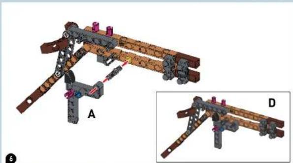
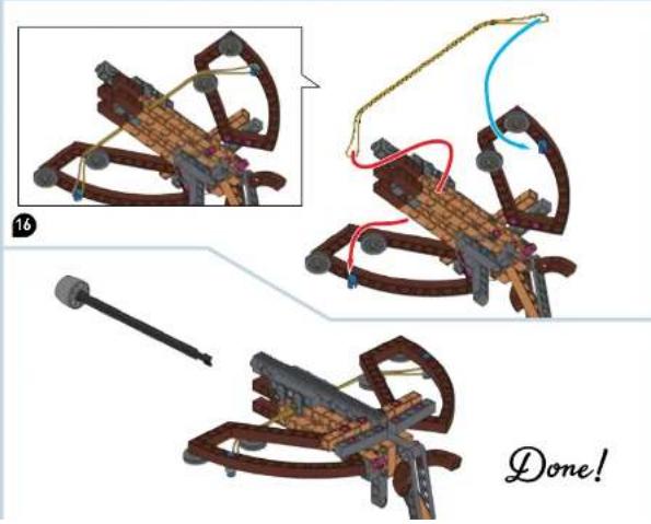
MODEL 2: REVERSE-DRAW CROSSBOW

A modern innovation in crossbow design is the placement of the limbs at the rear of the stock.
This arrangement provides several advantages over the classic crossbow design. Compare the design to the more traditional crossbow (model 4).
One advantage is that the modern crossbow allows the string to be in contact with the bolt for a longer amount of time. This means that more energy is transferred from the string to the bolt, giving it a greater velocity.


Catapult Engineering




Catapult Engineering


EXPERIMENT 2
How can you vary the velocity of the projectile?
Here's how:
- Stand at the mark you set up in the preparation steps.
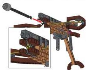
- Load a bolt into the crossbow by lining up the bolt with the plus-sign-shaped hole. Make sure both strands of the large rubber band are pushed inward by the bolt. Push the bolt inward until it clicks into place.
- Hold the crossbow horizontally. Release the bolt towards the target by pulling the trigger. Mark where the bolt lands using a piece of tape.
- Now stretch the rubber band around the other set of pulley wheels. What do you notice about the rubber band?
- Hold the crossbow at the same height and distance from the target when shooting the bolt. Measure and compare the distances the bolts traveled.
What happens when you pull the trigger?
What do you notice about the speed of the bolts?
Try looping the rubber hand around the pulley


WHAT'S HAPPENING?
As you learned in Experiment 1, when you stretch the rubber band tighter you add more potential energy to the rubber band. That means more potential energy to launch the bolt. This energy is then changed to kinetic energy, the energy of motion, which can be calculated by the equation
KE = 1 mv 2
MODEL 3: ONAGER


The onager is often what people think of when they think of a catapult. It gets its name from the Greek word meaning donkey, because of the kicking act ion of the machine. Originally, onagers released projectiles from slings.



Catapult Engineering


Catapult Engineering


WHAT'S HAPPENING?
If everything else remains the same, when the height from which the projectile is shot increases, the time that the object is in the air will also increase. Because the horizontal velocity of projectiles is constant, this also means that the projectile launched from the table will travel farther than the projectile launched from the floor. Maximizing the time that an object is in the air is important for a tennis lob, a football punt, and diving.
EXPERIMENT 3
How does varying the height of release impact the launch?
Here's how:
- Get a stopwatch ready. You will use this to measure the length of time the projectile is in the air.
- Place the cnager on the floor. Use the ratchet to wind up the string. Load a foam ball, and fire the ball by pressing the release trigger. How long was the projectile airborne?
- Now place the onager on the end

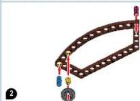
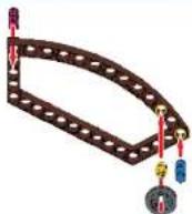
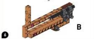
MODEL 4: CROSSBOW

The crossbow is a bow that has
been turned on its side and
mounted to a piece of wood
called a stock. Instead of an show sheets projectiles
a crossbow should be called bolts. The crossbow was
very popular throughout ancient
Europe and Asia because it was
faster to learn how to shoot
accurately with a crossbow then
it was w
regular how.




B

C

Catapult Engineering




Catapult Engineering


EXPERIMENT 4: HOOKE'S LAW
Here's how:
- Test the elasticity of the rubber band. Make different bundles of pennies and nickels using tissue paper and tape. (One penny is 2.5 grams; one nickel is 5 grams.)
- Tape a paper clip to the bundle to use as a hook.
- Hold the crossbow vertically and hang the weights from the large rubber band using the paper clip. Measure the
WHAT'S HAPPENING?
Hooke's law states that the distance that something elastic — like a rubber band — is stretched or compressed is directly proportional to the amount of force produced. This means that if the rubber band is stretched twice as far (for example, 2 inches instead of 1 inch) then the force produced would double. This is commonly written as:
F = -kx
where E is the form k in a constant
MODEL 5: TREBUCHET
Catapult Engineering

The trebuchet can be thought of as a giant seesaw where one side is pulled down causing the other side to go up and release a mass. Trebuchets developed from ancient slings and originated in China. The first trebuchet required a group of people to pull down on the lever arm in unison to launch the projectile.


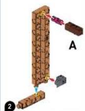

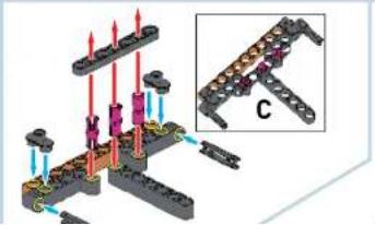


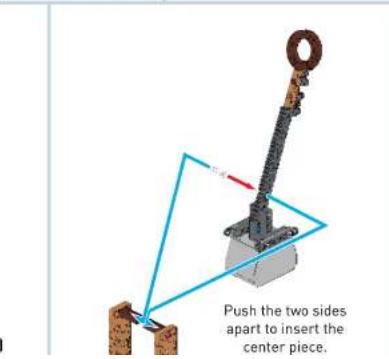
EXPERIMENT 5: LEVER ARMS
Here's how:
- Try launching the foam ball a few times with the model set up as shown. Lift up the counterweight and then let it drop. Try loading the basket with different amounts of weight.
- Now try varying the length of the lever arm by changing the hole where the pivot point, or fulcrum, is located. You can also try changing the length of the arm itself. Observe how far the projectile travels after each change.
- How could you improve the trebuchet using what you have learned from the crossbow models?


WHAT'S HAPPENING?
The trebuchet makes use of a simple machine called a lever. A lever is a beam that pivots at a fixed point called a fulcrum. A lever amplifies an input force to provide a greater output force. The ratio of the output to input force is given by the ratio of the distances from the fulcrum to the point of application of those forces. This ratio is known as the mechanical advantage of the lever. From your experiments you saw that the distance the ball travels increases as the main trebuchet arm
gets shorter and the load arm gets longer, but then decreases again. This is a result of changing the

EXPERMOREL GLOBALISTA
used a torsion spring to fire
instead of a string. Torsion
springs apply a force when
turned, instead of a normal
spring that develops a forced
When the spring is a short as compressed. An example of
a torsion spring you might be
familiar with is the spring in a
mouse trap. The torsion spring
allowed for the use of lighter
projectiles which could reach
higher velocities and greater distances.



Catapult Engineering


Catapult Engineering


EXPERIMENT 6
How does varying the angle of launch impact the flight?
Here's how:
- Test fire some bolts. Observe the paths that the bolts follow when they are shot from the ballista. Draw a picture of the path that a bolt follows as it flies through the air. How would you describe it?
- Shoot the ballista horizontally and mark the distance that the bolt travels with a piece of tape. Repeat this process holding the ballista at increasing angles (aiming it higher toward the ceiling).
What do you notice about the distances that the bolts travel before they hit the ground when shot at the different angles? What about the heights that the bolts travel?
At what angle does the bolt fly the farthest?

WHAT'S HAPPENING?

In physics, an object that has been launched into the air near Earth's surface is described by projectile motion. In experiment 6, you saw that the bolts followed an arc when they were shot out of the ballists. The shape of this arc changed when the angle at which the bolt was shot changed. You may have also found that the distance that the projectile traveled before hitting the ground increased as the angle increased and then decreased as you kept increasing the launch angle.
The figure above shows the distance that a projectile might travel if shot at the same velocity but different angles. Notice how the projectile goes the farthest when shot at a 45-degree angle. Why do you think this is?
The velocity vector of the bolt can be broken up into a horizontal and vertical part. When the projectile is shot at a 45-degree angle, the velocity is split evenly between the horizontal and vertical parts. The bolt has travels the greatest distance in the x direction when it

1st English Edition © 2023 Thames & Kosmos, LLC, Providence, RI, USA
Thames & Kosmos is a registered trademark of Thames & Cosmos, LLC.
This work, including all its parts, is copyright protected. Any use outside the specific limits of the copyright law is prohibited and punishable by law without the consent of the publisher. This applies specifically to reproductions, translations, microfilming, and storage and processing in electronic systems and networks. We do not guarantee that all material in this work is free from other copyright or other protection.
Text and Editing: Hannah Mintz, Ava Tessitore, and Ted McGuira
Technical product development: Genius Toys Taiwan Co., Ltd and Thames & Kosmos
Manual design concept: Atelier Bea Klenk, Berlin
Manual layout: Tess Sayward, Ava Tessitore
Manual illustrations: Siemens Tays Taiwan Co., Ltd.
Manual photos: Jaimie Duplass & beror (all adhesive strips, Oficola), istock.com/ Christian Reichenauer (crossbow, p. 10); istock.com/dja65 (catapult, p. 6); istock.com/ Ruben Pinto lantique crossbowl; istock.com/sgame (trebuchet, p. 25); istock.com/ akinshin rubber band ball, p. 91
Manual assembly instruction diagrams: Genus Toy Taiwan Co., Ltd
All remaining images: Thalmos & Kosmos, Franckh-Kosmos Verlags-GmbH & Co. KG
|Germanyl, Genius Toy Taiwan Co., Ltd.
Packaging layout: Dan Frietas
Packaging photos: Genius Teys Taiwan Co., Ltd
The publisher has made every effort to identify the owners of the rights to all photos used. If there is any instance in which the owners of the rights to any pictures have not been acknowledged, they are asked to inform the publisher about their copyright ownership so that they may receive the customary image fee.
Distributed in North America by Thames & Kosmos, LLC. Providence, RI 02903
Phone: 800-587-2872, Web www.thamesandkosmos.com
Distributed in United Kingdom by Thames & Kosmos UK LP, Cranbrook, Kent TN17 3HE
Phone: 01580 713000; Web: www.thamesandkosmos.co.uk
We reserve the right to make technical changes.
Printed in Taiwan / Imprimé en Taiwan

- CATAPULT ENGINEERING
- KIT CONTENTS
- CONTENTS
- ASSEMBLY STARTS ON PAGE 6
- TIP
- CHECKLIST
- SAFETY INFORMATION
- WARNING
- DEAR EXPLORERS
- ANCHOR PINS AND CONNECTORS
- AXLES
- PULLEYS AND RATCHETS
- IMPORTANT INFORMATION
- DEAR PARENTS AND ADULTS
- PREPARATION
- YOU WILL NEED
- HERE'S HOW
- WHAT'S HAPPENING
- KNOCKDOWN BLOCKS
- CASTLE WALLS
- EXPERIMENT 1
- EXPERIMENT 2
- EXPERIMENT 3
- EXPERIMENT 4: HOOKE'S LAW
- F = -KX
- EXPERIMENT 5: LEVER ARMS
- EXPERMOREL GLOBALISTA
- EXPERIMENT 6
Brand : Thames & Kosmos
Model : Catapult Engineering
Category : Educational toy