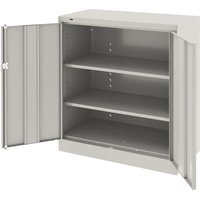
1442-LGY - Wardrobe Tennsco - Free user manual and instructions
Find the device manual for free 1442-LGY Tennsco in PDF.


| Product Type | Wardrobe Cabinet |
| Brand | Tennsco |
| Model | 1442-LGY |
| Color | Light Gray (LGY) |
| Material | Heavy-duty steel |
| Overall Height | 72 inches (182.9 cm) |
| Overall Width | 36 inches (91.4 cm) |
| Overall Depth | 18 inches (45.7 cm) |
| Weight | Approximately 110 lbs (49.9 kg) |
| Door Type | Single hinged door with lock |
| Lock Type | Key lock with 2 keys included |
| Shelves | 1 adjustable shelf (included) |
| Hanging Rod | Yes, included for garment hanging |
| Weight Capacity (shelf) | Up to 100 lbs (45.4 kg) evenly distributed |
| Weight Capacity (rod) | Up to 50 lbs (22.7 kg) |
| Finish | Powder-coated for durability |
| Assembly Required | Yes, with included hardware and instructions |
| Cleaning Instructions | Wipe with a damp cloth and mild detergent; avoid abrasives |
| Uses | Office, school, or home storage |
Frequently Asked Questions - 1442-LGY Tennsco
User questions about 1442-LGY Tennsco
0 question about this device. Answer the ones you know or ask your own.
Ask a new question about this device
Download the instructions for your Wardrobe in PDF format for free! Find your manual 1442-LGY - Tennsco and take your electronic device back in hand. On this page are published all the documents necessary for the use of your device. 1442-LGY by Tennsco.
USER MANUAL 1442-LGY Tennsco
ASSEMBLY INSTRUCTIONS & PARTS MANUAL
Standard Storage Cabinet
Unassembled Models 1442
tennsco®
Storage Made Easy
RETAIN INSTRUCTIONS FOR FUTURE REFERENCE

LOAD CAPACITIES PER SHELF LEVEL
EVENLY DISTRIBUTED
UNIT SIZE WEIGHT CAPACITY
36w x 18d 200 lbs.
GENERAL SAFETY INFORMATION
Some parts may have sharp edges. CARE must be taken when handling various pieces to avoid injury. For safety, wear a pair of work gloves when assembling or performing any maintenance on products.
LIMITED WARRANTY
Tennsco warrants goods purchased hereunder to be free of defects in materials and workmanship for a period of one (1) year from the date of shipment, hereunder. This warranty shall not apply in the event goods are damaged as a result of misuse, abuse, neglect, accident, improper application, modification or repair by persons not authorized by Seller, where goods are damaged during shipment, or where the date stamps on the goods have been defaced, modified or removed. UNLESS CONSIDERED UNENFORCEABLE OR UNLAWFUL UNDER APPLICABLE LAW:
a. ALL IMPLIED WARRANTIES, INCLUDING BUT NOT LIMITED TO WARRANTIES OR MERCHANTABILITY AND FITNESS FOR A PARTICULAR PURPOSE ARE HEREBY EXCLUDED:
b. BUYERS REMEDY, IF ANY, FOR ANY DEFECTIVE GOODS SHALL BE LIMITED TO A REFUND BY SELLER OR REPLACEMENT OF THE GOODS AT SELLER'S OPTION, AND SHALL IN NO EVENT INCLUDE DAMAGES OF ANY KIND, WHETHER INCIDENTAL, CONSEQUENTIAL OR OTHERWISE.
NO GOODS ACCEPTED FOR RETURN WITHOUT PRIOR APPROVAL. Seller shall have the right to inspect any goods claimed to be defective at Buyers place of business or require Buyer to return the goods to Seller for inspection on Seller's premises. Transportation charges covering returned goods will be borne by Seller only if such goods are proven to be defective, are covered by this warranty and are returned within the warranty period stated above.

PROUDLY MADE IN THE U.S.A.
Tennsco LLC., Dickson, TN 37056-1888 • (866) 446-8686
ASSEMBLY OF 1442 CABINET
Tools Needed: A free 11/32" nut driver is included with each Tennsco cabinet.
Two people are recommended for assembly. Approximate assembly time: 20-30 minutes.
- The reference numbers used throughout this sheet refer to the illustration on the back cover. This is to help you to identify the various parts as they are mentioned.
- Place the cabinet back (Ref. No. 1) on a protected surface to prevent scratching the paint. The flange on the bottom of the back should be facing upward.
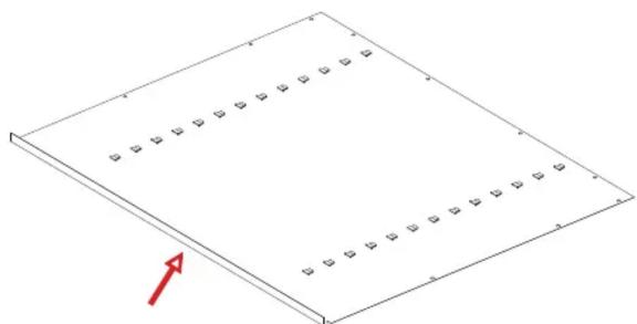
Flange faces upward.
- Attach the left side (Ref. No. 2) to the back by placing flange (A) around the back and bolting the back and side together with four bolts and nuts (Ref. Nos. 17 & 18). Be sure that the lances on all shelf adjustment strips (B) point in the same direction.

- Attach the top (Ref. No. 7) to the unit by sliding the outer flange over the back of the unit and the side flange to the side panel on the unit. The threaded studs should go through the holes in the
top flange of the side and fasten with three nuts. Attach the back to the top using four bolts and nuts.

- Attach the right side (Ref. No. 3) to the back in the same manner as you did in step 3, again making sure that the flange is around the back and that the lances on the shelf adjustment strips are pointed in the same direction as those on the back and left side. Push the side panel up so the studs in the top
go through the holes in the top flange of side and fasten with three nuts.

- Attach the sill (Ref. No. 5) to the sides. Place nuts loosely on each of the studs and slide the ends of the sill into the slots on both sides of the unit. Then, securely tighten the nuts.

- Place the rear flange of the bottom (Ref. No. 6) into the bottom lances of the back. The flange with two holes should face the front, hanging over the sill. Insert bolts through the bottom and sill with the head facing the front of the unit. Secure with two nuts.

- Set the unit upright and tighten all the nuts and bolts around the entire unit.
- Insert the shelves (Ref. No. 4) at the desired levels.
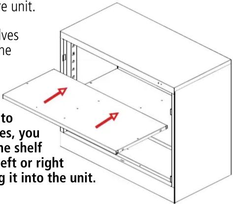
NOTE: In order to place the shelves, you must first tilt the shelf slightly to the left or right before inserting it into the unit.
- Attach the left door (Ref. No. 8) to the unit by placing the door on the hinges, aligning the hinge holes, dropping the pins into the slots, then placing the flat end of a
screwdriver on the hill (Ref. No. 15) and tapping them in with a hammer.

- Attach the right door (Ref. No. 9) to the unit in the same way you attached the left door.

- The cabinet must be level in order for the doors to close properly. Levelers may be adjusted by placing the nut driver through the hole in each end of the sill and adjusting the leveling screw.
Handle/Locking System Installation
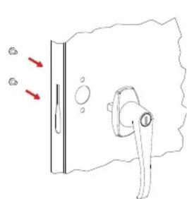
-
Place the locking handle (Ref. No. 9) on the right hand door and fasten with two #8-32 X 1/4 hex-head bolts and lock washers, provided with the handle.
-
Turn the handle to the open position and place the locking cam (Ref. No. 10) over the square shank of the door handle. The latch must be facing downward as shown. Then place the locking cotter pin (Ref. No. 12) through the hole of the square shank.

- With the handle still in the open position, hook the locking bars (Ref. No. 8) to the locking cam (see "A" at left). Once in position, slowly rotate the door handle to the closed position so the lock bars prot rude from the holes at the top and bottom of the door (shown at right, below).


- Slide the nylon lock bar guide inserts (Ref. No. 11) over the lock bar ends and through the door slots (see "B" at right). Push down firmly until the guides snap into place.
- Attach the "dummy" handle (Ref. No. 13) using two #8-32 X 1/4 hex-head bolts and lock washers.

REPLACEMENT PARTS

| 1442 (18"d Cabinet) | |||
| REF. NO. | DESCRIPTION | QTY. | PART NO. |
| 1 | Back Panel | 1 | 978BAS |
| 2 | Left Side | 1 | 978LSS |
| 3 | Right Side | 1 | 978RSS |
| 4 | Shelf | 2 | 301 |
| 5 | Top | 1 | 978CTS |
| 6 | Sill | 1 | 944SS |
| 7 | Left Door | 1 | 978LD |
| 8 | Right Door | 1 | 978RD |
| 9 | Bottom | 1 | 944BO |
| 10 | Locking Bar Set | 1 | 978LB |
| 11 | Locking Handle w/keys & hardware | 1 | 944LH |
| 12 | Locking Cam* | 1 | 944LC |
| 13 | Locking Bar Guide Insert (Nylon)* | 2 | 944GI |
| 14 | Cotter Pin* | 1 | CTRPN |
| 15 | Hinge Pin* | 6 | 944HP |
| 16 | Tennsco Nut Driver | 1 | TOOL-2 |
| 17 | #8-32 x 3/8" bolts (not shown above) | 14 | ** |
| 18 | #8-32 nuts (not shown above) | 24 | ** |
*Included in Ref. No. 11, locking handle with keys and hardware (Part No. 944LH).
**Available Locally
NOTE: Additional hardware may be included for replacement purposes.
Brand : Tennsco
Model : 1442-LGY
Category : Wardrobe