200977 - Generator Champion - Free user manual and instructions
Find the device manual for free 200977 Champion in PDF.


| Product Type | Portable Generator |
| Brand | Champion |
| Model | 200977 |
| Power Output (Running) | 3500 Watts |
| Power Output (Starting) | 4000 Watts |
| Fuel Type | Gasoline |
| Engine Displacement | 224 cc |
| Runtime at 50% Load | 12 hours |
| Fuel Tank Capacity | 3.5 gallons |
| Starting System | Recoil Start |
| Outlets | 2x 120V 20A GFCI, 1x 120/240V 30A RV, 1x 12V DC |
| Dimensions (L x W x H) | 24 x 18 x 20 inches |
| Weight | 95 lbs |
| Noise Level | 68 dBA at 25 ft |
| Safety Features | Low Oil Shutdown, CO Detection, Circuit Breaker |
| Maintenance | Oil change every 50 hours, air filter cleaning monthly |
| Warranty | 3 years limited |
| Compliance | EPA, CARB |
Frequently Asked Questions - 200977 Champion
User questions about 200977 Champion
0 question about this device. Answer the ones you know or ask your own.
Ask a new question about this device
Download the instructions for your Generator in PDF format for free! Find your manual 200977 - Champion and take your electronic device back in hand. On this page are published all the documents necessary for the use of your device. 200977 by Champion.
USER MANUAL 200977 Champion
at championpowerequipment.com



or visit championpowerequipment.com
SAvE THESE INSTRUCTIONS. This manual contains important safety precautions which should be read and understood before operating the product. Failure to do so could result in serious injury. This manual should remain with the product.
Specifications, descriptions and illustrations in this manual are as accurate as known at the time of publication, but are subject to change without notice.
Covered by one or more of the following U.S. Patent Numbers: 10,641,187 and other U.S. and foreign patents pending.

CARBON MONOXIDE SAFETY: THE BIG PICTURE
As the only safe way to use a portable generator, taking your generator outside is absolutely mandatory to keep your family safe from carbon monoxide. But there's even more you can do. By educating yourself about all carbon monoxide risks, you'll be better prepared to protect your family from this colorless, oderless threat.

www.TakeYourGeneratorOutside.com
TABLE OF CONTENTS
Introduction 4
Safety Definitions 4
Important Safety Instructions 5
Fuel Safety 7
Safety and Dataplate Labels 8
Safety Symbols 9
Operation Symbols 10
Quickstart Label Symbols 11
Controls and Features 12
Generator 12
Control Panel 13
Side Panel 13
Intelligauge 14
FCC Statement 15
Parts Included 15
Assembly 16
Unpacking 16
Remove Shipping Support Spacers 16
Add Engine Oil 16
Add Fuel: Gasoline 17
Add Fuel: Propane (LPG) 18
Grounding 19
Operation 20
Generator Location 20
Surge Protection 20
Starting the Engine: Gasoline 20
Starting the Engine: Propane (LPG) 21
Connecting Electrical Loads 23
Do Not Overload Generator 23
Eco (Economy) Mode 24
Parallel Operation 24
Stopping the Engine 24
Moving the Generator 25
Operation at High Altitude 25
Maintenance 26
Cleaning the Generator 26
Changing the Engine Oil 26
Cleaning and Adjusting the Spark Plug 27
Cleaning the Air Filter 27
Cleaning the Spark Arrestor 27
Adjusting the Governor 28
Maintenance Schedule 28
Storage 28
Short Term Storage (up to 30 days) 28
Mid Term Storage (30 days - 1 year) 29
Long Term Storage (more than 1 year) 29
Removing from Storage 30
Specifications 31
Generator Specifications 31
Engine Specifications 31
Oil Specifications 31
Fuel Specifications 31
Temperature Specifications 31
Troubleshooting 32
Warranty* 34
Warranty Qualifications 34
Repair/Replacement Warranty 34
Do Not Return The Unit To The Place Of Purchase 34
Warranty Exclusions 34
Other Exclusions 34
Limits of Implied Warranty and Consequential Damage 34
Contact Information 34
INTRODUCTION
Congratulations on your purchase of a Champion Power Equipment (CPE) product. CPE designs, builds, and supports all of our products to strict specifications and guidelines. With proper product knowledge, safe use, and regular maintenance, this product should bring years of satisfying service.
Every effort has been made to ensure the accuracy and completeness of the information in this manual at the time of publication, and we reserve the right to change, alter and/or improve the product and this document at any time without prior notice.
CPE highly values how our products are designed, manufactured, operated, and serviced as well as providing safety to the operator and those around the generator. Therefore, it is IMPORTANT to review this product manual and other product materials thoroughly and be fully aware and knowledgeable of the assembly, operation, dangers and maintenance of the product before use. Fully familiarize yourself, and make sure others who plan on operating the product fully familiarize themselves too, with the proper safety and operation procedures before each use. Please always exercise common sense and always err on the side of caution when operating the product to ensure no accident, property damage, or injury occurs. We want you to continue to use and be satisfied with your CPE product for years to come.
When contacting CPE about parts and/or service, you will need to supply the complete model and serial numbers of your product. Transcribe the information found on your product's nameplate label to the table below
CPE TECHNICAL SUPPORT TEAM
1-877-338-0999
MODEL NUMBER
200977
SERIAL NUMBER
DATE OF PURCHASE
PURCHASE LOCATION
SAFETY DEFINITIONS
The purpose of safety symbols is to attract your attention to possible dangers. The safety symbols, and their explanations, deserve your careful attention and understanding. The safety warnings do not by themselves eliminate any danger. The instructions or warnings they give are not substitutes for proper accident prevention measures.
DANGER
DANGER indicates a hazardous situation which, if not avoided, will result in death or serious injury.
WARNING
WARNING indicates a hazardous situation which, if not avoided, could result in death or serious injury.
CAUTION
CAUTION indicates a hazardous situation which, if not avoided, could result in minor or moderate injury.
NOTICE
NOTICE indicates information considered important, but not hazard-related (e.g., messages relating to property damage).
IMPORTANT SAFETY INSTRUCTIONS
WARNING
Cancer and Reproductive Harm – www.P65Warnings.ca.gov
DANGER
Generator exhaust contains carbon monoxide, a colorless, odorless, poisonous gas. Breathing carbon monoxide will cause nausea, dizziness, fainting or death. If you start to feel dizzy or weak, get to fresh air immediately.
OPERATE GENERATOR OUTDOORS ONLY IN A WELL VENTILATED AREA AND POINT EXHAUST AWAY.
DO NOT operate the generator inside any building, including garages, basements, crawlspaces and sheds, enclosure or compartment, including the generator compartment of a recreational vehicle.
DO NOT allow exhaust fumes to enter a confined area through windows, doors, vents or other openings.
DANGER
Using a generator indoors CAN KILL YOU IN MINUTES.
Generator exhaust contains carbon monoxide. This is a poison you cannot see or smell.
NEVER use inside a home or garage, EVEN IF doors and windows are open.
ONLY use OUTSIDE and far away from windows, doors, and vents.

Install battery-operated carbon monoxide alarms or plug-in carbon monoxide alarms with battery back-up according to the manufacturer's instructions.
WARNING
Although the generator contains a spark arrester, maintain a minimum distance of 5 ft. (1.5 m) from dry vegetation to prevent fires.
DANGER
Operate equipment with guards in place.
Rotating parts can entangle hands, feet, hair, clothing and/or accessories. Traumatic amputation or severe laceration can result.
Keep hands and feet away from rotating parts.
Tie up long hair and remove jewelry.
DO NOT wear loose-fitting clothing, dangling drawstrings or items that could become caught.
DANGER
Generator produces powerful voltage.
DO NOT touch bare wires or receptacles.
DO NOT use electrical cords that are worn, damaged or frayed. Use only Champion electrical cords for proper application.
DO NOT operate generator in wet weather.
DO NOT allow children or unqualified persons to operate or service the generator.
Use a ground fault circuit interrupter (GFCI) in damp areas and areas containing conductive material such as metal decking.
Connection to your home's electrical system requires a listed 30A transfer switch installed by a licensed electrician and approved by the local authority having jurisdiction. The connection must isolate the generator from the utility power and must comply with all applicable laws and electrical codes.
WARNING
Do not use generator for medical and life support uses.
In case of emergency, call 911 immediately.
NEVER use this product to power life support devices or life support appliances.
NEVER use this product to power medical devices or medical appliances.
Inform your electricity provider immediately if you or anyone in your household depends on electrical equipment to live.
Inform your electrical provider immediately if a loss of power would cause you or anyone in your household to experience a medical emergency.
WARNING
Spark from removed spark plug wire can result in fire or electrical shock.
When servicing the generator:
Disconnect the spark plug wire and place it where it cannot contact the plug or any other metal object.
DO NOT check for spark with the plug removed.
Use only approved spark plug testers.
⚠ WARNING
Running engines produce heat. Severe burns can occur on contact. Combustible material can catch fire on contact.
DO NOT touch hot surfaces.
Avoid contact with hot exhaust gases.
Allow equipment to cool before touching.
Maintain at least 3 ft. (91.4 cm) of clearance on all sides to ensure adequate cooling.
Maintain at least 5 ft. (1.5 m) of clearance from combustible materials.
⚠ WARNING
Rapid retraction of the recoil cord will pull hand and arm towards the engine faster than you can let go. Broken bones, fractures, bruises or sprains could result. Unintentional startup can result in entanglement, traumatic amputation or laceration.
When starting engine, pull the recoil cord slowly until resistance is felt and then pull rapidly to avoid kickback.
DO NOT start or stop the engine with electrical devices plugged in and turned on.
CAUTION
Exceeding the generator's running capacity can damage the generator and/or electrical devices connected to it.
DO NOT overload the generator.
DO NOT tamper with the governed speed.
DO NOT modify the generator in any way.
CAUTION
Start the generator and allow the engine to stabilize before connecting electrical loads.
Connect electrical equipment in the off position, and then turn them on for operation.
Turn electrical equipment off and disconnect before stopping the generator.
CAUTION
Improper treatment or use of the generator can damage it, shorten its life or void the warranty.
Use the generator only for intended uses.
Operate only on level surfaces.
DO NOT expose generator to excessive moisture, dust, or dirt.
DO NOT allow any material to block the cooling slots.
If connected devices overheat, turn them off and disconnect them from the generator.
DO NOT use the generator if:
–Electrical output is lost
–Equipment sparks, smokes or emits flames
—Equipment vibrates excessively
Fuel Safety
DANGER
GASOLINE, GASOLINE VAPORS AND PROPANE (LPG) ARE HIGHLY FLAMMABLE AND EXPLOSIVE.
Fire or explosion can cause severe burns or death.
Gasoline and gasoline vapors:
—Gasoline is highly flammable and explosive.
—Gasoline can cause a fire or explosion if ignited.
—Gasoline is a liquid fuel but it's vapors can ignite.
—Gasoline is a skin irritant and needs to be cleaned up immediately if spilled on skin or clothes.
- Gasoline has a distinctive odor, this will help detect potential leaks quickly.
-In any petroleum gas fire, flames should not be extinguished unless by doing so the fuel supply valve can be turned OFF. This is because if a fire is extinguished and a supply of fuel is not turned OFF, then an explosion hazard could be created.
—Gasoline expands or contracts with ambient temperatures. Never fill the gasoline tank to full capacity, as gasoline needs room to expand if temperatures rise.
LPG:
-LPG is highly flammable and explosive.
–LPG is under pressure and can cause a fire or explosion if ignited.
-LPG is heavier than air and can settle in low places while dissipating.
- LPG has a distinctive odor added to help detect potential leaks quickly.
-In any petroleum gas fire, flames should not be extinguished unless by doing so the fuel supply valve is turned OFF. This is because if a fire is extinguished and a supply of fuel is not turned OFF, then an explosion hazard could be created.
- When exchanging LPG cylinders, check that the cylinder valve is of the same type.
—Always keep the LPG cylinder in an upright position.
- LPG will burn skin if it comes in contact with it. Keep any and all LPG away from skin at all times.
When adding or removing gasoline:
DO NOT light or smoke cigarettes.
Turn the generator off and let cool for at least two minutes before removing the gasoline cap. Always loosen the cap slowly to relieve pressure in the tank.
Only fill or drain gasoline outdoors in a well-ventilated area.
DO NOT pump gasoline directly into the generator at the gas station. Always use an approved container to transfer the fuel to the generator.
DO NOT overfill the gasoline tank.
Always keep gasoline away from sparks, open flames, pilot lights, heat and other sources of ignition.
When starting the generator:
DO NOT attempt to start a damaged generator.
Always check that the gasoline cap, air filter, spark plug, fuel lines and exhaust system are properly in place.
Always allow spilled gasoline to evaporate fully before attempting to start the engine.
Always be certain that the generator is resting firmly on level ground.
When operating the generator:
DO NOT move or tip the generator during operation.
When transporting or servicing the generator:
Always check that the fuel valve is in the OFF position and the gasoline tank is empty.
For LPG compatible models, check that the LPG cylinder is disconnected and stored securely away from the generator.
Disconnect the spark plug wire.
When storing the generator:
Store away from sparks, open flames, pilot lights, heat and other sources of ignition.
Do not store generator, gasoline or LPG cylinders near furnaces, water heaters, or any other appliances that produce heat or have automatic ignitions.
DANGER
NEVER place a gasoline container, gasoline tank, LPG cylinder or any combustible material in the path of the exhaust stream during operation of the engine.
WARNING
Never use a gasoline container, gasoline tank, LPG connector hose, LPG cylinder or any other fuel item that is broken, cut, torn or damaged.
Safety and Dataplate Labels
These labels warn you of potential hazards that can cause serious injury. Read them carefully.
If a label comes off or becomes hard to read, contact Technical Support Team for possible replacement.
Top

Side

Back
LABEL DESCRIPTION
| A | 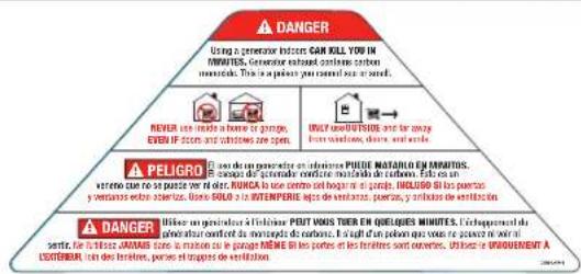 | CO Danger | ||||
| B |  | Safety Symbols | ||||
| C |  | Fuel | ||||
| D |  | Hot Surface | ||||
| E | CHAMPION POWER EQUIPMENT, INC.12039 SMITH AVENUESANTA FE SPRINGS, CA 90670USA / E-U.1-877-338-0999WWW.CHAMPIONPOWEREQUIPMENT.COMMADE IN CHINA / FABRIQUE EN CHINE20H-7/P4 | FREQUENCY (Hz)FRÉQUENCE (Hz) | 60 | MAX AMBIENT TEMP.TEMP.AMBIANTE MAX.104°F40°C | Dataplate | |
| RPMTR / MIN | 3600 | GASOLNE WATTSWATTS DESSENCE3500 | ||||
| INSULATION CLASSCLASSE DIBOLATION | F | PROpane WATSWATTS AU PROPANE3150 | ||||
| MODELMODELE | 200977 | POWER FACTORFACTUR DEPUSSANCE | 1.0 | |||
| SERIAL NO.N° DE SÉRIE | XXXXXXXXXX | AC VOLTSVOLTS C.A. | 120 | |||
| MANUFACTURE DATEDATE DE FABRICATION | XXXX | AC AMPSAMPERES C.A. | 29.2 | |||
| CHAMPION POWER EQUIPMENT, INC. 12039 SMITH AVENUE SANTA FE SPRINGS, CA 90070 USA / C.U. 1-877-338-0899 WWW.CHAMPIONPOWEREQUIPMENT.COM MADE IN CHINA / FABRIQUE EN CHINE | FREQUENCY (Hz) FREQUENCY (Hz) | 60 | MAX AMBIENT TEMP. TEMP. AMBIENTE MAX. | 104°F 40°C | |
| RPM TR / MIN | 3600 | GASLINE WATTS WATTS GESSENCE | 3500 | ||
| INSULATION CLASS CLASSE DIBOLATION | F | PROPANE WATTS WATTS AU PROPANE | 3150 | ||
| MODEL MODELE | 200977 | POWER FACTOR FACTUR DE PUSANCE | 1.0 | 8 17 198 02 397 7 | |
| SERIAL NO. N° DE Série | XXXXXXXXXX | AC VOLTS VOLTS C.A. | 120 | ||
| MANUFACTURE DATE DATE DE FABRICATION | XXXX | AC AMPS AMPERES C.A. | 29.2 | ||
Safety Symbols
Some of the following symbols may be used on this product. Please study them and learn their meaning. Proper interpretation of these symbols will allow you to more safely operate the product.
| SYMBOL MEANING | |
 | Read Operator's Manual. To reduce the risk of injury, user must read and understand operator's manual before using this product. |
 | Clearance. Keep all objects at least 5 feet (1.5m) from generator. Heat from the muffler and exhaust gas can ignite combustible objects. |
 | Ground. Consult with local electrician to determine grounding requirements before operation. |
 | Electric Shock. Failure to use in dry conditions and to observe safe practices can result in electric shock. Improper connections to a building can allow current to backfeed into utility lines, creating an electrocution hazard. A transfer switch must be used when connecting to a building. |
 | Fire/Explosion. Fuel and its vapors are extremely flammable and explosive. Fire or explosion can cause severe burns or death. Keep generator at least 5 feet (1.5m) from all objects to prevent combustion. |
 | Hot Surface. To reduce the risk of injury or damage, avoid contact with any hot surface. |
 | Open Flame Alert. Fuel and its vapors are extremely flammable and explosive. Keep fuel away from smoking, open flames, sparks, pilot lights, heat, and other ignition sources. |
 | Wet Conditions Alert. Do not expose to rain or use in damp locations. |
Operation Symbols
Some of the following symbols may be used on this product. Please study them and learn their meaning. Proper interpretation of these symbols will allow you to more safely operate the product.
| SYMBOL MEANING | |
 | Engine Run: Gasoline |
 | Stop or Off |
 | Fuel/Gasoline Valve Off |
 | Engine Run: Propane |
 | Economy Mode Button |
 | Low Oil |
 | Overload Reset Button |
 | Propane Hose Inlet |
 | Choke |
 | Run |
 | USB Connection Port |
| SYMBOL MEANING | |
 | Parallel Connection(s) |
 | Hertz |
| [AG2C] | Volts |
 | Run time |
 | RV Ready Receptacle |
 | Neutral Floating. Neutral circuit IS NOT electrically connected to the frame/ground of the generator. |
 | Ground Terminal |
 | Gasoline Tank: Full |
 | Gasoline Tank: Empty |
 | Circuit Breaker Reset: Push |
 | 5V 2.1A Direct Current |
Quickstart Label Symbols
Some of the following symbols may be used on this product. Please study them and learn their meaning. Proper interpretation of these symbols will allow you to more safely operate the product.

Starting the Engine- Manual Start
! DANGER
Move generator outside and far away from windows, doors and intake ventilation covers.
- Check oil level.
Recommended oil is 10W-30. - Check gasoline level.
When adding gasoline, use a minimum octane rating of 87 and an ethanol content of 10% or less by volume. - Turn the fuel selector dial to gasoline "RUN" position.
- Move choke lever to "CHOKE" position.
- Pull the recoil cord.
- Move the choke lever to "RUN" position.
- Plug in desired device.
Stopping the Engine
- Turn off and unplug all connected electrical loads.
- Turn the fuel selector dial to the "OFF" or STOP position.
For adding fuel and starting the engine with LPG see Add Fuel: Propane (LPG) in Assembly section and Starting the Engine: Propane (LPG) in the Operation section.
CONTROLS AND FEATURES
Read this operator's manual before operating your generator. Familiarize yourself with the location and function of the controls and features. Save this manual for future reference.
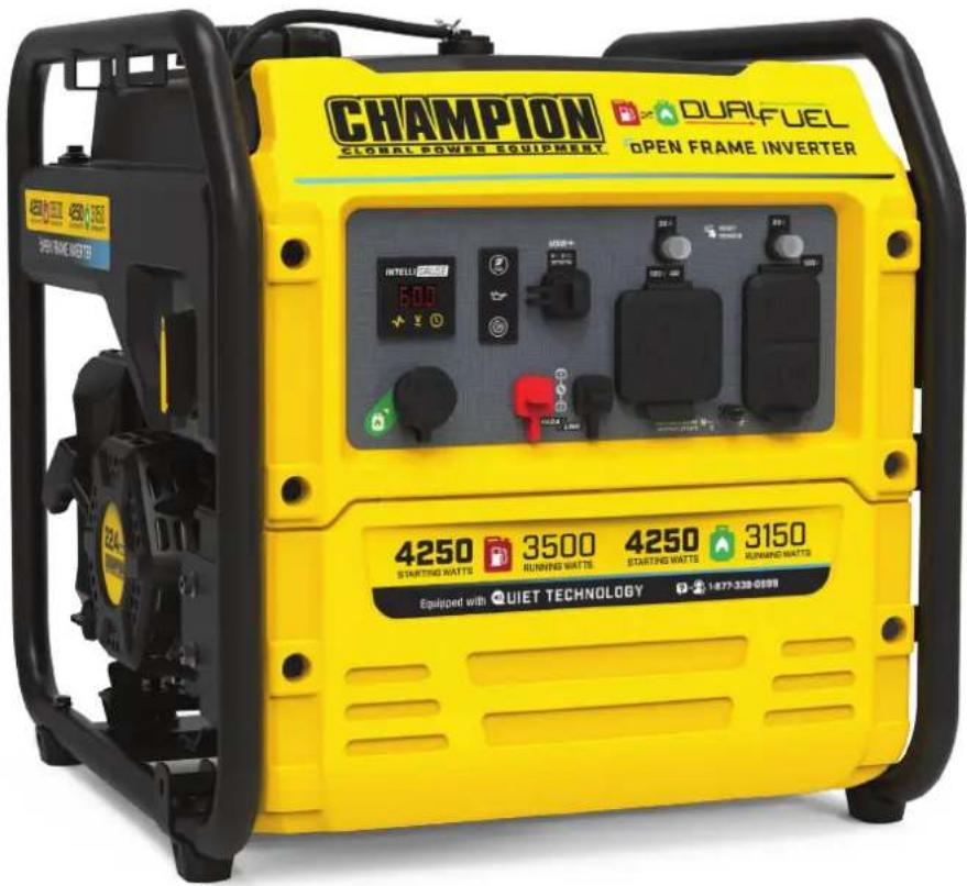
Generator


- Gasoline Tank - 4 gal. (15.2 L)
- Gasoline Gauge
- Fuel Cap – Remove to add fuel.
- Choke - Used to start the engine.
- Air Filter – Protects the engine by filtering dust and debris from the intake air.
-
Side Panel – See Side Panel section.
-
Recoil Starter – Used to manually start the engine.
- Control Panel – See Control Panel section.
- Muffler
- Oil Drain Bolt – Used to quickly drain engine oil.
- Oil Fill Cap/Dipstick – Used to check and fill oil level.
Control Panel

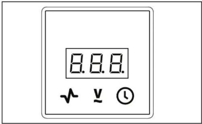
- Intelligauge – Three mode digital meter for displaying voltage, frequency (hertz) and run time.
- Economy Mode Button – Enables/disables automatic idle control.
- Low Oil Warning Indicator Light – When ON, engine will shut down and not run. Check oil level.
- AC Overload Reset Button – Used to re-energize receptacles after overload fault.
- LPG Inlet - Used to connect LPG fuel source to generator.
- Parallel Outlets – Used to parallel two inverters together for increased power output. (parallel kit sold separately).
- Circuit Breakers (Push Reset) – Protects the generator against electrical overloads.
- Ground Terminal – Consult an electrician for local grounding regulations.
| RECEPTACLES | ||
| A |  | (2×) 5V DC, 2.1A (USB Type-A)Each port may be used to supply a maximum of 5V, 2.1A to power cellphones, laptops, tablets, and similar devices. |
| B |  | 120V AC, 30A RV (NEMA TT-30R)May be used to supply electrical power for operation of 120 Volt AC, 30 Amp, single phase, 60 Hz electrical loads. |
| C |  | (2×) 120V AC, 20A (NEMA 5-20R)May be used to supply electrical power for operation of 120 Volt AC, 20 Amp, single phase, 60 Hz electrical loads. |
Side Panel

- Fuel Selector Dial – Used to turn on gasoline or propane (LPG) fuel source, turn off the gasoline (fuel valve), and STOP the engine.
Intelligauge
Three mode digital meter for displaying frequency (hertz), voltage, and total run time.
The LCD displays each mode for several seconds and then automatically cycles through.
| MODE DESCRIPTION | ||
 Frequency (Hz) Frequency (Hz) | Output frequency in hertz. | |
| Example: 60.0 hertz | 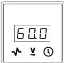 | |
 Voltage (V) Voltage (V) | Output voltage of the generator. | |
| Example: 120 volts |  | |
 Total Run Time (Hrs.) Total Run Time (Hrs.) | Total run time of the generator since first operation | |
| Example: 16 hours |  | |
FCC Statement
- This device complies with Part 15 of the FCC Rules. Operation is subject to the following two conditions:
1a. This device may not cause harmful interference.
1b. This device must accept any interference received, including interference that may cause undesired operation.
- Changes or modifications not expressly approved by the party responsible for compliance could void the user's authority to operate the equipment.
A NOTICE
This equipment has been tested and found to comply with the limits for a Class B digital device, pursuant to Part 15 of the FCC Rules. These limits are designed to provide reasonable protection against harmful interference in a residential installation. This equipment generates, uses and can radiate radio frequency energy and if not installed and used in accordance with the instructions, may cause harmful interference to radio communications. However, there is no guarantee that interference will not occur in a particular installation. If this equipment does cause harmful interference to radio or television reception, which can be determined by turning the equipment off and on, the user is encouraged to try to correct the interference by one or more of the following measures:
-Reorient or relocate the receiving antenna.
—Increase the separation between the equipment and receiver.
-Connect the equipment into an outlet on a circuit different from that to which the receiver is connected.
Consult dealer or an experienced radio/TV technician for help.
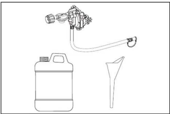
Parts Included
Accessories
Engine Oil 20.3 fl. oz. (600 ml)
Oil Funnel 1
6 ft. (1.8 m) LPG Hose with Regulator 1
ASSEMBLY
Your generator requires some assembly. It must be properly serviced with fuel and oil before operation.
If you have any questions regarding the assembly of your generator, call our Technical Support Team at 1-877-338-0999. Please have your serial number and model number available.
Unpacking
- Set the shipping carton on a solid, flat surface.
- Remove everything from the carton except the generator.
- By lifting up on the frame of the unit, carefully remove the generator from the box (two people lifting is recommended).
Remove Shipping Support Spacers
To protect the generator during shipping, support spacers have been installed between the engine and frame. These spacers MUST BE REMOVED BEFORE adding oil or gasoline to the generator.

NOTICE
DO NOT attempt to run generator without first removing the shipping support spacers. Damage to the generator as a result of not removing the spacers will void the warranty.
- BEFORE filling the engine with oil or gasoline, tip the generator onto its side as shown. Tip onto the flattened cardboard box the generator came in or other protective surface so as to not scratch the frame.
- Remove the bolts from the orange support spacers and remove the spacers while lightly lifting the engine. Bolts and spacers can be discarded.
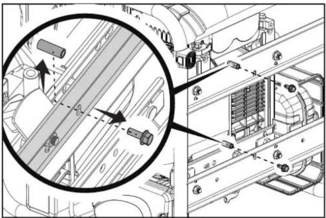
- Tip the generator upright.
Add Engine Oil

WARNING
DO NOT attempt to crank or start the engine before it has been properly filled with the recommended type and amount of oil. Damage to the generator as a result of failing to follow these instructions will void your warranty.

NOTICE
The generator rotor has a sealed, pre-lubricated ball bearing that requires no additional lubrication for the life of the bearing.

NOTICE
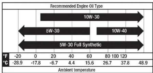
The recommended oil type for typical use is 10W-30 automotive oil. However, using the listed conventional oils shown in the "Recommended Engine Oil Type" chart may be used for typical use including the first 5 hours of the break-in run time period of the engine.
If running generator in extreme temperatures, refer to the "Recommended Engine Oil Type" chart.
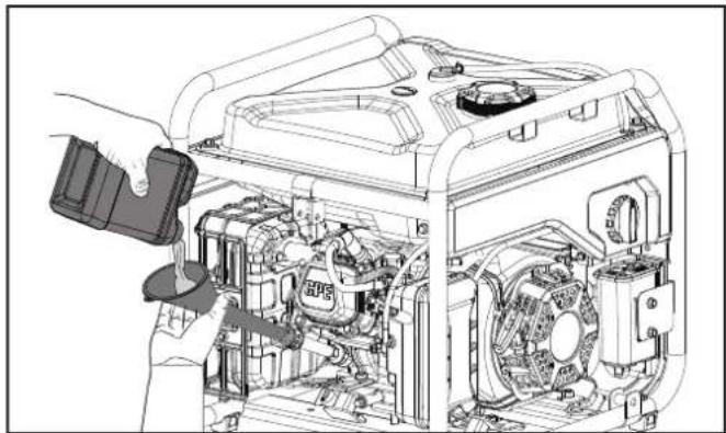
- Place the generator on a flat, level surface.
- Remove oil fill cap/dipstick to add oil.
- Using a funnel, add up to 20.3 fl. oz. (600 ml) of oil (included) and replace oil fill cap/dipstick. DO NOT OVERFILL.
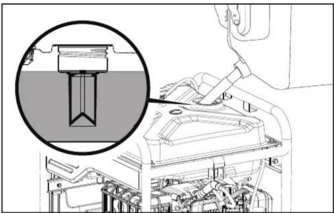
- Check engine oil level at every use and add as needed.


NOTICE
Once oil has been added, a visual check should show oil about 1-2 threads from running out of the fill hole.
When using the dipstick to check oil level, DO NOT screw in the dipstick while checking.

NOTICE
Check oil level often during the break-in period. Refer to the Maintenance section for recommended service intervals.

CAUTION
This engine is equipped with a low oil shut-off and will stop when the oil level in the crankcase falls below the threshold level.

NOTICE
The first 5 hours of run time are the break-in period for the unit. During the break in period stay at or below 50% of the running watt rating and vary the load occasionally to allow stator windings to heat and cool. Adjusting the load will also cause engine speed to vary slightly and help seat piston rings. After the 5 hour break-in period, change the oil.

NOTICE
Synthetic oil may be used after the 5 hour initial break-in period. Using synthetic oil does not decrease the recommended oil change interval. Full synthetic 5W-30 oil will aid in starting in cold ambient < 41°F (5°C) temperatures.
Add Fuel: Gasoline
! DANGER
Gasoline vapors are highly flammable and extremely explosive.
DO NOT light or smoke cigarettes. Fire or explosion can cause severe burns or death.
Only fill or drain fuel outdoors in a well-ventilated area. DO NOT pump gasoline directly into the generator. Use an approved container to transfer the fuel to the generator.
Never use a gasoline container, gasoline tank, or any other fuel item that is broken, cut, torn or damaged.
DO NOT overfill the gasoline tank. Always keep fuel away from sparks, open flames, pilot lights, heat and other sources of ignition.
Use clean, fresh, regular unleaded gasoline with a minimum octane rating of 87 and an ethanol content of 10% or less by volume. E10 E45 E65
DO NOT mix oil with gasoline.
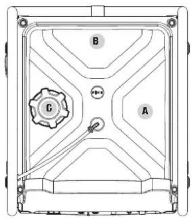
- Remove the gasoline cap.
- Slowly add gasoline to the tank. DO NOT OVERFILL. Gasoline can expand after filling. A minimum of 1/4 in. (6.4 mm) of space left in the tank is required for gasoline expansion, although more than 1/4 in. (6.4 mm) is recommended. Gasoline can be forced out of the tank as a result of expansion if overfilled, and can affect the stable running condition of the generator.
- The approximate fuel level is shown on the fuel gauge on top of the fuel tank.
![graph TD A["Empty"] --> B["Full"] style A fill:#f9f,stroke:#333 style B fill:#bbf,stroke:#333](/content/2026/07/1429488/images/1cb0f5f1aed164b8ea86a7b0c8783befcaf4d7f356a41ba8816eac74da227d14.jpg)
- Screw on the gasoline cap and wipe away any spilled fuel.
CAUTION
Use unleaded gasoline with a minimum octane rating of 87 and an ethanol content of 10% or less by volume.
DO NOT light cigarettes or smoke when filling the tank.
DO NOT mix oil and gasoline.
DO NOT overfill the tank. Fill tank to approximately 1/4 in.
(6.4 mm) below the top of the tank to allow for gasoline expansion.
DO NOT pump gasoline directly into the generator at the pump. Use an approved fuel container to transfer the gasoline to the generator.
DO NOT fill tank indoors.
DO NOT fill tank when the engine is running or hot.
WARNING
Pouring gasoline too fast through the fuel screen may result in gasoline splashing over the generator and operator while filling.
NOTICE
The generator engine works well with 10% or less ethanol blended gasoline. When using ethanol-gasoline blends there are some issues worth noting:
–Ethanol-gasoline blends can absorb more water than gasoline alone.
- These ethanol blends can eventually separate, leaving water or a watery goo in the tank, fuel valve and carburetor. The compromised gasoline can be drawn into the carburetor and cause damage to the engine and/or create potential hazards.
- If a fuel stabilizer is used, confirm that it is formulated to work with ethanol-gasoline blends.
- Any damages or hazards caused by using ethanol blended gasoline higher than 10% by volume, improperly stored gasoline, and/or improperly formulated stabilizers, are not covered by manufacturer's warranty.
It is advisable to always shut off the gasoline supply and run the engine to starvation after each use. See Storage instructions for extended non-use.
Add Fuel: Propane (LPG)
! DANGER
NEVER place the LPG (liquefied petroleum gas) connector hose OR LPG cylinder tank in the path of the muffler exhaust gas stream of the generator during engine operation.
- Confirm the dial is in the OFF position.
- If using a new propane cylinder, remove the plastic cap from the cylinder valve.
- Attach the LPG hose assembly (included) to the propane cylinder valve and hand tighten until snug. DO NOT OVER TIGHTEN.
- Remove the rubber boot covering the propane connection port on the inverter.
- Align the plastic finger on the male hose fitting on the LPG hose assembly with the slot next to the female quick connect coupling on the inverter.
- Insert the hose fitting into the quick connect coupling and push in until you hear a "click" and the outside collar of the quick connect coupling moves forward.

- Check all connections for leaks by wetting the fittings with a solution of soap and water. Bubbles which appear or bubbles which grow indicate that a leak exists. If a leak exists at a fitting then turn off the valve on the cylinder and tighten the fitting. Turn the valve back on and recheck the fitting with the soap and water solution. If the leak continues or if the leak is not at a fitting then do not use the generator and contact customer service.

NOTICE
—The LPG hose included with this unit works with standard 20 and 30 pound LPG tanks.
—Verify the requalification date on the cylinder has not expired.
- Always position the cylinder so the connection between the cylinder valve and generator inlet won't cause sharp bends or kinks in the LPG hose.

CAUTION
Do not allow children to tamper or play with the LPG cylinder or hose connections.

CAUTION
Use approved LPG cylinders equipped with an OPD (overfilling prevention device) valve. Always keep the cylinder in a vertical position with the valve on top and installed at ground level on a flat surface. Cylinders must not be installed near any heat source and should not be exposed to sun, rain, and dust. When transporting and storing, turn off the cylinder valve and generator LPG valve, and disconnect the cylinder. Plug the outlet, usually by a plastic protective cap, if one is available. Keep cylinders away from heat and ventilated when in a vehicle.

WARNING
If there is a strong smell of LPG: Close valve on the cylinder. Check all connections for leaks by wetting the fittings with a solution of soap and water. Bubbles which appear or bubbles which grow indicate that a leak exists. Do not smoke or light a cigarette, or check for leaks using a match, open flame source or lighter. Contact a qualified technician to inspect and repair an LPG system if a leak is found, before using the generator.
Grounding
Your generator must be properly connected to an appropriate ground to help prevent electric shock.

WARNING
Failure to properly ground the generator can result in electric shock.
A ground terminal connected to the panel of the generator has been provided (see Controls and Features for terminal location). For remote grounding, connect a length of heavy gauge (12 AWG Panel) copper wire between the generator ground terminal and a copper rod driven into the ground. We strongly recommend that you consult with a qualified electrician to ensure compliance with local electrical codes.
Neutral Floating*
- Neutral circuit IS NOT electrically connected to the frame/ground of the generator.
- The generator (stator winding) is isolated from the frame and from the AC receptacle ground pin.
–Electrical devices that require a grounded receptacle pin connection will not function if the receptacle ground pin is not functional.
Neutral Bonded to Frame*
- Neutral circuit IS electrically connected to the frame/ground of the generator.
-The generator system ground connects lower frame cross-member below the alternator. The system ground is connected to the AC neutral wire.
* See your Specifications section for specified type of grounding.
OPERATION
Generator Location
WARNING
NEVER operate the generator inside any building, garage, basement, crawlspace, shed, enclosure or compartment, including a generator compartment of a recreational vehicle.
NEVER operate or start the generator in the back of an SUV, camper, trailer, truck bed (regular sides, flat or other configuration), under staircases, stairwells, next to walls or buildings or in any other location that will not allow for adequate cooling of the generator or for the proper exit of the exhaust flow from the muffler system.
DO NOT operate or store the generator in wet weather conditions such as rain or snow. Using a generator in wet conditions could result in serious injury or death due to electrocution.
In some state's generators may be required to be registered with the local utility company when used at construction sites and may be subject to additional rules and regulations, consult your local municipal authority.
Generators should always be operated on a flat, level surface at all times (even when not in operation).
Generators must have a minimum of 5 feet (1.5 m) of clearance from all combustible material.
Generators must also have a minimum of 3 feet (91.4 cm) of air flow clearance on all sides to allow for adequate performance cooling, maintenance and servicing.
Always place the generator in a well-ventilated area. NEVER place the generator near air intake vents or where exhaust fumes could be drawn into occupied or confined spaces.
Always carefully consider wind and air currents when positioning generator.
Always allow generators to properly cool before transport or for storage purposes.
Failure to follow proper safety precautions may result in personal injury, damage to the generator and void the manufacturer's warranty.
WARNING
During operation the muffler and exhaust fumes will become hot. If adequate cooling and breathing space are not supplied, or if the generator is blocked or enclosed, temperatures can become extremely heated and may lead to fire.
WARNING
Do not expose to rain or use in damp locations.
Keep all objects a minimum of 5 feet (1.5m) away from the generator at all times. Heat from the muffler surface and exhaust gas stream can ignite combustible materials.
WARNING
If you must operate in rain or damp locations, DO NOT operate without proper protection of the electrical components.
Use of a safety canopy that is fire retardant and will provide proper air ventilation for the engine exhaust gas stream may be used.
Visit championpowerequipment.com or call to find your Storm Shield cover.
Surge Protection
Electronic devices, including computers and many programmable appliances use components that are designed to operate within a narrow voltage range and may be affected by momentary voltage fluctuations. While there is no way to prevent voltage fluctuations, you can take steps to protect sensitive electronic equipment.
—Install UL1449, CSA-listed, plug-in surge suppressors on the outlets feeding your sensitive equipment.
Surge suppressors come in single- or multi-outlet styles.
They're designed to protect against virtually all short-duration voltage fluctuations.
Starting the Engine: Gasoline
- Make certain the generator is on a flat, level surface.
- Disconnect all electrical loads from the generator. Never start or stop the generator with electrical devices plugged in or turned on.
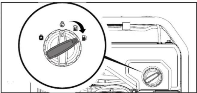
- Turn the fuel selector dial to the gasoline "RUN" position.
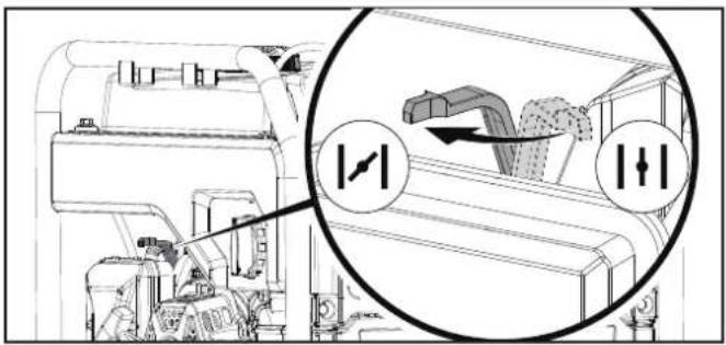
- Move the choke to the "CHOKE" position.
4a. For restarting a warm engine, move the choke to 75% of the "CHOKE" position.
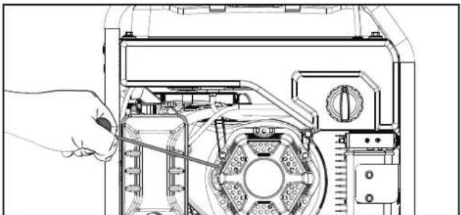
- Pull the recoil cord slowly until resistance is felt and then pull rapidly.
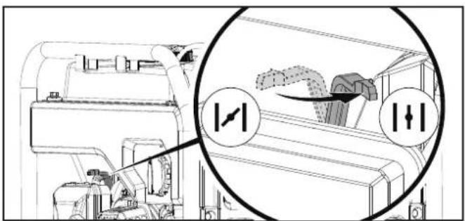
- Do not over-choke. As soon as engine starts, move the choke to the gasoline "RUN" position over a 2-5 second duration.

NOTICE
For gasoline restarts with hot engine in hot ambient > 86°F (30°C), keep choke in 75% of the "CHOKE" position for only 1 pull of the recoil cord. After first pull, move choke to "RUN" position for up to 3 pulls of the recoil cord. Too much choke leads to spark plug fouling/engine flooding due to lack of incoming air. This will cause the engine not to start.

NOTICE
For gas starting in cold ambient temperature < 59°F (15°C), the choke must be in 100% of the "CHOKE" position. Do not over-choke. As soon as engine starts, gradually move the choke lever to the "RUN" position over a 2-5 second duration.

NOTICE
If the engine starts but does not run make certain that the generator is on a flat, level surface. The engine is equipped with a low oil sensor that will prevent the engine from running when the oil level falls below a critical threshold.
Starting the Engine: Propane (LPG)
- Make certain the generator is on a flat, level surface.
- Disconnect all electrical loads from the generator. Never start or stop the generator with electrical devices plugged in or turned on.
- Make sure the fuel selector dial is set to LPG operation.

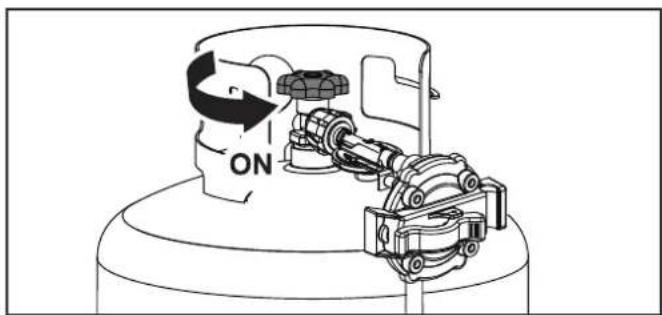
- Fully open the fuel valve on the LPG cylinder.
- Move the choke to the "CHOKE" position.
5a. For restarting a warm engine, move the choke to the same position.

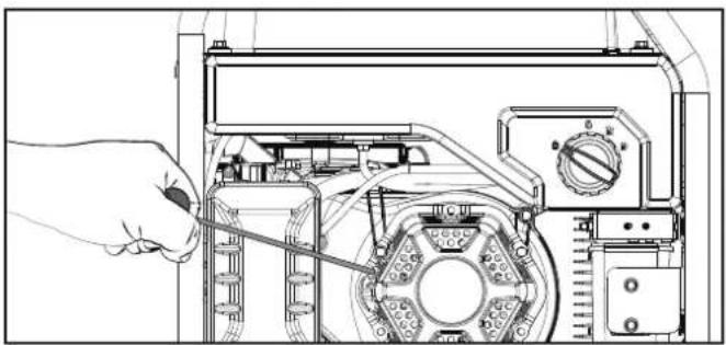
- PULL-TO-PRIME: Pull the recoil cord slowly until resistance is felt and then pull rapidly. Pull with 100% "CHOKE" 3-5 times until you feel a few combustion pulses that indicates that the engine momentarily started.
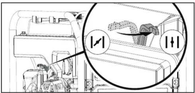
- Move the choke to the propane "RUN" position.
- Pull the recoil cord slowly until resistance is felt and then pull rapidly.

- If engine fails to start in 1-pull with choke in the "RUN", then move choke to the "CHOKE" position and repeat the PULL-TO-PRIME step.
NOTICE
For LPG starting in cold ambient temperature < 59°F (15°C), storing the LPG hose and regulator indoors may improve starting as cold temperatures can stiffen the rubber of the regulator diaphragm and prevent proper priming. If the LPG hose feels stiff from cold temperatures, the engine may take more pulls to prime or the hose and regulator may be moved indoors to warm up.
NOTICE
If the engine starts but does not run make certain that the generator is on a flat, level surface. The engine is equipped with a low oil sensor that will prevent the engine from running when the oil level falls below a critical threshold.
NOTICE
Accumulation of frost on LPG cylinder and regulators is common during operation and normally is not an indication of a problem. As LPG vaporizes and travels from the cylinder to the generator engine it expands. The amount of frost that forms can be affected by the size of the cylinder, the amount of LPG being used, the humidity of the air and other operating conditions.
In unusual situations this frost may eventually restrict the flow of LPG to the generator resulting in deteriorating performance. For example, if the cylinder temperature is reduced to a very low level then the rate at which the LPG vaporizes is also reduced and may not provide sufficient flow to the engine. This is not an indication of a problem with the generator but only a problem with the flow of LPG from the cylinder. If generator performance seems to be deteriorating at the same time that ice formation is observed on tank valve, hose or regulator then some actions may be taken to eliminate this symptom.
In these rare situations it can be helpful to reduce or eliminate the cold fuel system effects by doing one of the following:
-Exchanging fuel cylinders to allow the first cylinder to warm up, repeating as necessary.
-Placing the cylinder at the end of the generator near the handle, where engine fan air flows out from the generator. This air is slightly heated by flowing over the engine. The cylinder should not be placed in the path of the muffler outlet.
—The cylinder can be temporarily warmed by pouring warm water over the top of the cylinder.
Connecting Electrical Loads
Let the engine stabilize and warm up for a few minutes after starting.
Plug in and turn on the desired 120 or 240 (if applicable) Volt AC single phase, 60 Hz electrical loads.
-DO NOT connect 3-phase loads to the generator.
-DO NOT overload the generator.
WARNING
Always remember to plug your appliances directly into the generator and do not plug the generator power cord into any electrical outlet or connect to the circuit breaker panel in your home. Connecting a generator to your home's electric utility company's power lines, or to another power source, called 'backfeeding' is a dangerous practice that is illegal in many states and municipalities.
This action if done incorrectly could damage your generator, appliances and could cause serious injury or death to you or a utility worker when attempting to restore power during an outage occurrence in the neighborhood who may then unexpectedly encounter high voltage on the utility line and suffer a fatal shock.
Whether injuries occur or not, if installed incorrectly and not to applicable laws and codes, you may be subject to fines or the utility company may disconnect your home power should this practice be found in your home.
If the generator will be connected to a building electrical system, those connections must isolate the generator power from the utility power. You are responsible for ensuring your generator's electricity does not backfeed into the electric utility power lines. These connections must comply with all applicable laws and codes – Consult your local utility company or a qualified electrician to properly install this connection.
Do Not Overload Generator
Capacity
Follow these simple steps to calculate the running and starting watts necessary for your purposes:
- Select the electrical devices you plan on running at the same time.
- Total the running watts of these items. This is the amount of power you need to keep your items running.
-
Identify the highest starting wattage of all devices identified in step 1. Add this number to the number calculated in step 2. Starting wattage is the surge of power needed to start some electric driven equipment. Following the steps listed under "Power Management" will guarantee that only one device will be starting at a time.
-
If the generator power output is cut off due to an overload condition indicated by the AC overload blinking light, lower the load by unplugging one or more items, then press the AC overload reset button before restarting the generator for continued normal operation.

Power Management
Use the following formula to convert voltage and amperage to watts:
Volts × Amps = Watts
To prolong the life of your generator and attached devices, follow these steps to add electrical load:
- Start the generator with no electrical load attached.
- Allow the engine to run for several minutes to get up to temperature.
- Make sure all circuit breakers are set to the run position.
- Plug in and turn on the first item. It is best to attach the item with the largest load first.
- Allow the engine to stabilize.
- Plug in and turn on the next item.
- Allow the engine to stabilize.
- Repeat steps 5-6 for each additional item.
NOTICE
Never exceed the specified capacity when adding loads to the generator.
Eco (Economy) Mode
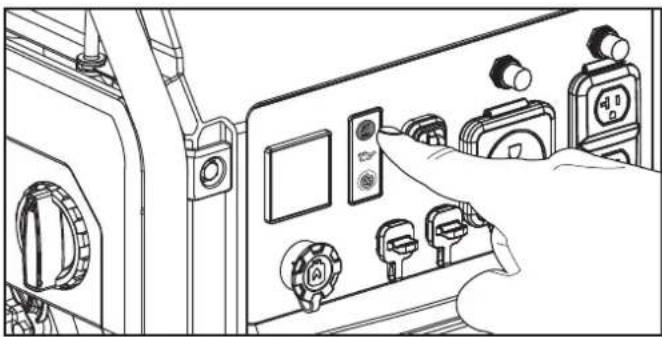
The Eco Mode button can be activated to turn on economy control in order to minimize fuel consumption and noise while operating the unit during times of reduced electrical output. Eco Mode allows the engine speed to idle during periods of non-use.
The engine speed returns to normal when an electrical load is connected. When the economy switch is off, the engine runs at normal speed continuously.
CAUTION
For periods of high electrical load or momentary fluctuations, the Eco Mode should be off.
Parallel Operation
The Champion model 200977 is parallel ready and can be operated in parallel with another Champion unit to increase the total available electrical power. A Champion parallel kit (optional equipment) is required for parallel operation. Model 100319 is the recommended model for this unit. For a list of compatible models or to order a parallel kit, please call customer service at 1-877-338-0999 or visit
www.championpowerequipment.com.
Detailed instructions for parallel kit installation and operation of the connected generators are provided in the parallel kit operator's manual.
Stopping the Engine
-
Turn off and unplug all connected electrical loads. Never start or stop the generator with electrical devices plugged in or turned on.
-
Let the generator run at no-load for several minutes to stabilize internal temperatures of the engine and generator.
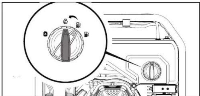
3. If operating by gasoline:
3a. Turn the fuel selctor dial to the "gasoline off" position.

3b. Once the generator runs out of fuel, turn fuel selector dial to the "STOP" position.
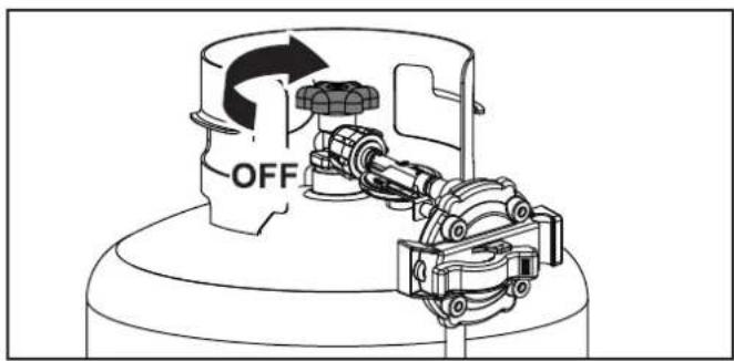
4. If operating by propane (LPG):
4a. Fully close the fuel valve on the LPG cylinder.
4b. Once the generator runs out of fuel, turn fuel selector dial to the "STOP" position.
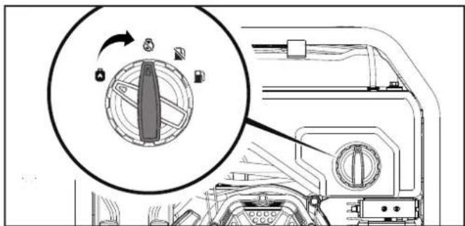
Important: Always ensure that controls are in the "OFF" or STOP position when the generator is not in use.

NOTICE
If the engine will not be used for a period of two (2) weeks or longer, please see the Storage section for proper engine and fuel storage.
Moving the Generator

CAUTION
-ALWAYS turn the generator off and ensure the fuel valve is closed.
-ALWAYS make sure engine and muffler are cooled down before the generator can be handled safely (typically 15-30 minutes).
—Do not drop or strike unit or place under heavy objects.

WARNING
Failure to follow these instructions could result in personal injury or damage to the generator.
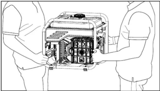
Lift unit up by the frame with 2 people and move to the desired location.
Operation at High Altitude
The density of air at high altitudes is lower than at sea level. Engine power is reduced as the air mass and air-fuel ratio decrease. Engine power and generator output will be reduced approximately 3½% for every 1000 ft. of elevation above sea level. At high altitudes increased exhaust emissions can also result due to the increased enrichment of the air fuel ratio. Other high altitude issues can include hard starting, increased fuel consumption and spark plug fouling.
To alleviate high altitude issues other than the natural power loss, CPE can provide a high altitude carburetor main jet. The alternative main jet and installation instructions can be obtained by contacting our Technical Support Team. Installation instructions are also available in the Technical Bulletin area of the CPE website.
The part number and recommended altitude range for the application of the high altitude carburetor main jet is listed in the following table.
In order to select the correct high altitude main jet it is necessary to identify the carburetor model. For this purpose, a code is stamped on the side of the carburetor. Select the correct high altitude jet part number corresponding to the carburetor code found on your particular carburetor.
| Carb. Code | High Alt. Jet Part Number | Altitude Range |
| 100714246 10005 | 6226 | 1000 ft.-3000 ft.(305 m-914 m) |

WARNING
Operation using the alternative main jet at elevations lower than the recommended minimum altitude can damage the engine. For operation at lower elevations, the originally supplied standard main jet must be used. Operating the engine with the wrong engine configuration at a given altitude may increase its emissions and decrease fuel efficiency and performance.
MAINTENANCE
Make certain that the generator is kept clean and stored properly. Only operate the unit on a flat, level surface in a clean, dry operating environment. DO NOT expose the unit to extreme conditions, excessive dust, dirt, moisture or corrosive vapors.
WARNING
Never operate a damaged or defective generator.
WARNING
Improper maintenance will void your warranty.
NOTICE
For Emission control devices and systems, read and understand your responsibilities for service as stated in the Emission Control Warranty Statement of this manual.
The owner/operator is responsible for all periodic maintenance.
Complete all scheduled maintenance in a timely manner.
Correct any issue before operating the generator.
For service or parts assistance, contact our Technical Support Team at 1-877-338-0999.
Cleaning the Generator
CAUTION
DO NOT spray generator directly with water.
Water can enter the generator through the cooling slots and damage the generator windings. It can also contaminate the fuel system.
- Use a damp cloth to clean exterior surfaces of the generator.
- Use a soft bristle brush to remove dirt and oil.
- Use an air compressor (25 PSI) to clear dirt and debris from the generator.
- Inspect all air vents and cooling slots to ensure that they are clean and unobstructed.
To prevent accidental starting, remove and ground the spark plug wire before performing any service.
Changing the Engine Oil
Change oil when the engine is warm. Refer to the oil specification to select the proper grade for your operating environment.
- While holding the flat part of the drain tube with pliers or wrench, remove the oil drain bolt with a 10 mm socket (not included) or wrench.
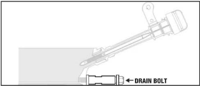
- Allow the oil to drain completely into an appropriate container.
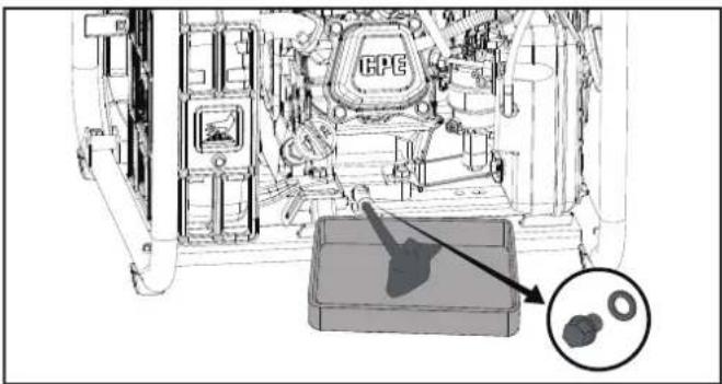
- Replace the oil drain bolt.
- Add oil according to Add Engine Oil in Assembly section. DO NOT OVERFILL. Oil not included for routine maintenance.
- Dispose of used oil at an approved waste management facility.
NOTICE
Once oil has been added, a visual check should show oil about 1-2 threads from running out of the fill hole. If using the dipstick to check oil level, DO NOT screw in the dipstick while checking.
Cleaning and Adjusting the Spark Plug
- Remove the spark plug cable from the spark plug.
- Use a spark plug socket tool (not included), or a 13/16 in. (21 mm) socket (not included) to remove the plug.
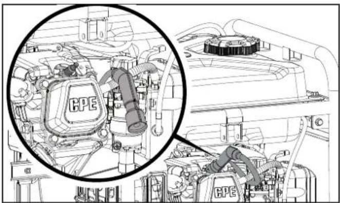
- Inspect the electrode on the plug. It must be clean and not worn to produce the spark required for ignition.
- Make certain the spark plug gap is 0.024-0.031 in. (0.6-0.8 mm).
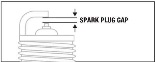
- Refer to the spark plug types in Specifications when replacing the plug.
- Firmly re-install the plug.
- Attach the spark plug cable to the spark plug.
Cleaning the Air Filter
- Unscrew the cover holding the air filter to the assembly by turning the fastener counterclockwise.
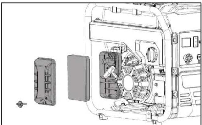
- Remove the foam element.
- Wash in liquid detergent and water. Squeeze thoroughly dry in a clean cloth.
- Saturate in clean engine oil.
- Squeeze in a clean, absorbent cloth to remove all excess oil.
- Place the filter in the assembly.
- Reattach the air filter cover and tighten the fastener by turning clockwise.
Cleaning the Spark Arrestor
- Allow the engine to cool completely before servicing the spark arrestor.
- Remove the two screws holding the cover plate which retains the spark arrestor to the muffler.
- Remove the spark arrestor screen.
- Carefully remove the carbon deposits from the spark arrestor screen with a wire brush.

- Replace the spark arrestor if it is damaged.
- Position the spark arrestor on the muffler and attach with the screws removed in step 2.
CAUTION
Failure to clean the spark arrestor will result in degraded engine performance.
NOTICE
Federal and local laws and administrative requirements indicate when and where spark arrestors are required. When ordered, spark arrestors are required for operation of this generator in National Forest lands. In California, this generator must not be used on any forest-covered land, brush-covered land, or grass-covered land unless the engine is equipped with a spark arrestor.
Adjusting the Governor
WARNING
Tampering with the factory set governor will void your warranty.
The air-fuel mixture is not adjustable. Tampering with the governor can damage your generator and your electrical devices and will void your warranty. Contact our Technical Support Team at 1-877-338-0999 for all other service and/or adjustment needs.
Maintenance Schedule
Follow the service intervals indicated in the following maintenance schedule.
Service your generator more frequently when operating in adverse conditions.
Contact our Technical Support Team at 1-877-338-0999 to locate the nearest CPE certified service dealer for your generator or engine maintenance needs.
EVERY 8 HOURS OR PRIOR TO EACH USE
□ Check oil level
□ Clean around air intake and muffler
□ Check propane (LPG) hose for leaks
FIRST 5 HOURS (BREAK IN)
□ Change oil
EVERY 50 HOURS OR ANNUALLY
□ Clean air filter
☐ Change oil if operating under heavy load or in hot environments
EVERY 100 HOURS OR ANNUALLY
□ Change oil
□ Clean/adjust spark plug
□ Clean spark arrestor
□ Clean fuel valve filter*
EVERY 250 HOURS
□ Clean combustion chamber*
□ Check/adjust valve clearance*
EVERY 3 YEARS
□ Replace fuel line*
□ Replace LPG hose
* To be performed by knowledgeable, experienced owners or CPE certified service centers.
STORAGE
WARNING
To avoid accidental or unintended ignition of your generator during periods of storage, the following precautions should be followed:
- When storing the generator make sure the fuel selector dial is set to the "STOP" position. Turn the fuel selector dial to the "STOP" position.
NOTICE
The following storage instructions apply when gasoline has been used to run the generator. NOTE: LPG does not apply and will not create build up or clog the carburetor.
Short Term Storage (up to 30 days)
Gasoline in the gasoline tank has a maximum shelf life of up to 1 year with the addition of properly formulated fuel stabilizers and if stored in a cool, dry place. Gasoline in the carburetor, however, may gum up and clog the carburetor if it isn't used or drained within 2-4 weeks.
If using the generator within 2 weeks, follow the steps according to Stopping the Engine section.
- If not using the generator for 2-4 weeks, begin by making sure all appliances are disconnected from the generator.
- Start the generator as instructed in Starting the Engine: Gasoline section.
- Turn the fuel selector dial to the Gasoline Valve Off position.
- After the engine stops, turn the fuel selector dial to the "STOP" position.
Mid Term Storage (30 days - 1 year)
Gasoline in the tank has a maximum shelf life of up to 1 year with the addition of a properly formulated fuel stabilizer and stored in a cool, dry place.
- Be sure all appliances are disconnected from the generator.
- Add a properly formulated fuel stabilizer to the gasoline tank.
- Start engine by following directions in the Starting the Engine: Gasoline section.
- Run the generator for 10 minutes so the treated gasoline cycles through the fuel system and carburetor.
- Turn the fuel selector dial to the Gasoline Valve Off position.
- After the engine stops, turn the fuel selector dial to the "STOP" position.
- After fuel has run out and the engine has stopped, allow the engine to cool.
- Locate and remove the spark plug by referencing the Cleaning and Adjusting the Spark Plug section
- After removing the spark plug pour about a tablespoon of oil into the cylinder.
- SLOWLY pull the recoil to rotate the engine to distribute and lubricate the cylinder.
- Re-install the spark plug and spark plug wire.
- Clean the generator according to Cleaning the Generator.
- Store the generator in a cool, dry place out of direct sunlight.
Long Term Storage (more than 1 year)
For storage over 1 year, the gasoline tank and carburetor must be completely drained of gasoline.
- Be sure all appliances are disconnected from generator.
- Place inverter on blocks to allow appropriate gasoline container or pan to slide under inverter.
- Turn the fuel selector dial to the gasoline "RUN" position.
- Using a Phillips screwdriver, rotate drain screw counterclockwise (3) full turns. Gasoline will drain through clear tubing out underneath the inverter. Make sure draining gasoline empties into an appropriate container.
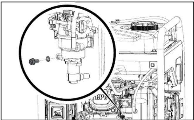
- When gasoline stops flowing from the clear tube, rotate drain screw clockwise until tight. Properly dispose of the drained gasoline according to local regulations or guidelines.
- Turn the fuel selector dial to the "STOP" position.
- Follow steps 8-13 according to Short Term Storage.
Removing from Storage

NOTICE
If the generator has been improperly stored for a period longer than 30 days with ethanol blended gasoline in the gasoline tank and/or carburetor, all fuel must be drained and the carburetor must be thoroughly cleaned of ethanol build up. This process involves technically advanced tasks. For assistance please call our Technical Support Team at 1-877-338-0999.
If the gasoline tank and carburetor were properly emptied of all ethanol blended gasoline prior to the generator being stored, follow the below steps when removing from storage.

WARNING
If there is a strong smell of LPG: Close valve on the cylinder. Check all connections for leaks by wetting the fittings with a solution of soap and water. Bubbles which appear or bubbles which grow indicate that a leak exists. Do not smoke or light a cigarette, or check for leaks using a match, open flame source or lighter. Contact a qualified technician to inspect and repair an LPG system if a leak is found, before using the generator.
- Be sure the fuel selector dial is in the "STOP" position.
- Add gasoline to the generator according to Add Fuel.
- Turn the fuel selector dial to the gasoline "RUN" position.
- After 5 minutes check the carburetor and air filter areas for any leaking gasoline. If any leaks are found, the carburetor will need to be disassembled and cleaned or replaced. If no gasoline leaks are found, turn the fuel selector dial to the "STOP" position.
- Check engine oil level and add clean, fresh oil if needed. See Oil Specifications for proper oil type.
- Check and clear air filter of any obstructions such as bugs or cobwebs. If necessary, clean air filter according to Cleaning the Air Filter.
- Start the generator according to Starting the Engine.
SPECIFICATIONS
Generator Specifications
| Generator Model | 200977 |
| Start Type | Manual |
| Watts (Starting/Running) | 4250/3500 |
| Watts (LPG) (Starting/Running) | 4250/3150 |
| Volts AC | 120 |
| AC Amps @ 120V | 29.2 |
| Volts DC | 5 |
| DC Amps | 2.1 |
| Frequency | 60 Hz |
| Phase | Single |
| Grounding Type | Neutral Floating |
| Weight | 79 lb. (36 kg) |
| Length | 20.9 in. (53.2 cm) |
| Width | 18.3 in. (46.6 cm) |
| Height | 19.4 in. (49.4 cm) |
Engine Specifications
| Model | GB225M-2 |
| Displacement | 224 cc |
| Type | 4-Stroke OHV |
Spark Plug
| OEM Type | F6RTC |
| Replacement Type | NGK BPR6ES or equivalent |
| Gap | 0.024-0.031 in. (0.6-0.8 mm) |
Valve
| Intake Clearance | 0.004-0.006 in. (0.10-0.15 mm) |
| Exhaust Clearance | 0.006-0.008 in. (0.15-0.20 mm) |

NOTICE
A technical bulletin regarding valve adjustment procedures is available at www.championpowerequipment.com.
Oil Specifications
DO NOT OVERFILL.
| Type | *See following chart |
| Capacity | 20.3 fl. oz. (600 ml) |


NOTICE
Temperature will affect engine oil and engine performance. Change the type of engine oil used based on temperature shown in the “Recommended Engine Oil Type” table.
Fuel Specifications
Use unleaded gasoline with a minimum octane rating of 87 and an ethanol content of 10% or less by volume. DO NOT USE E15 or E85. DO NOT OVERFILL.
Gasoline Capacity 4 gal. (15.2 L)
Propane (LPG)
- Use only an approved LPG cylinder equipped with an OPD (overfilling prevention device) valve.
Temperature Specifications
Starting Temperature Range (°F/°C) 5 to 104/-15 to 40

NOTICE
An important message about temperature: Your product is designed and rated for continuous operation at ambient temperatures up to 104°F (40°C). When needed, it may be operated at temperatures ranging from 5°F (-15°C) to 122°F (50°C) for short periods of time. If exposed to temperatures outside this range during storage, it should be brought back within this range before operation. In any event, the product must always be operated outdoors, in a well-ventilated area and away from doors, windows and vents.
TROUBLESHOOTING
| Problem Cause Solution | ||
| Engine will not start. | No fuel. Add fuel. | |
| Faulty spark plug. Clean and adjust spark plug or replace. | ||
| Low oil level. | Fill crankcase to the proper level. | |
| Place generator on a flat, level surface. | ||
| Spark plug wire loose. Attach wire to spark plug. | ||
| Fuel valve is closed. Open fuel valve. | ||
| Fuel selector dial in the STOP position. | Rotate the fuel selector dial to either fuel selection and start normally, either electrically or manually. | |
| Old fuel or water in fuel. Drain fuel and replace with fresh fuel. | ||
| Flooded with fuel. Let unit stand for 10 mins. | ||
| Engine starts but runs roughly. | Choke in the wrong position. | Move choke until it stops under RUN position or push in completely. |
| Dirty air filter. Clean or replace air filter. | ||
| Dirty fuel valve. Clean the fuel valve. | ||
| Clogged spark arrestor. Clean spark arrestor. | ||
| Engine will not start electrically. | Generator battery is dead. Recharge generator battery. | |
| Battery switch is in the OFF position. Turn battery switch to ON position. | ||
| Engine shuts down during operation. | Out of fuel. | Fill fuel tank. |
| Low oil level. | Fill crankcase to the proper level. Place generator on a flat, level surface. | |
| Clogged spark arrestor. Clean spark arrestor. | ||
| Generator cannot supply enough power or overheating. | Generator is overloaded. | Review load and adjust. See “Connecting Electrical Loads.” |
| Dirty air filter. | Clean or replace air filter. | |
| Choke in wrong position. | Move choke until it stops under RUN position or push in completely. | |
| Engine is running but no AC output. | Poor cord connection. | Check all connections. |
| Circuit breaker is open. | Reset circuit breaker. Check all circuit breakers. | |
| Faulty brush assembly. | Replace brush assembly (Service Center). | |
| Faulty AVR (auto voltage regulator). | Replace AVR (Service Center). | |
| Loose wiring. | Inspect and tighten wiring connections. | |
| AC Overload: Button illuminated red | Reduce AC load and press Overload Reset Button until illuminated green. | |
| Other. | Contact the help line. | |
| Engine hunts or falters. | Engine governor defective. Contact the help line. | |
| Dirty fuel valve. Clean the fuel valve. | ||
| Carburetor is dirty and running lean. Contact the help line. | ||
| Choke in wrong position. | Move choke until it stops under RUN position or push in completely. | |
| DUAL FUEL MODELS ONLY: Engine will not stop. | Propane valve is still open. | Turn the propane valve to the CLOSED position on the tank. |
| DUAL FUEL MODELS ONLY:Engine will not start in cold weather. | LPG Regulator diaphragm is too stiff to prime engine. | Store or move LPG hose and regulator indoors to warm up or repeat starting instructions until started. |
| Repeated circuit breaker tripping. | Overload. | Review load and adjust. See “Connecting Electrical Loads.” |
| Faulty power cords or device. | Check for damaged, bare or frayed wires. Replace defective device. | |
| Circuit breaker still too hot. Let unit sit for 5 mins. | ||
For other issues and technical support:
Technical Support Team
Toll Free 1-877-338-0999
support@championpowerequipment.com
WARRANTY*
CHAMPION POWER EQUIPMENT
3 YEAR LIMITED WARRANTY
Warranty Qualifications
To register your product for warranty and FREE lifetime call center technical support please visit:
https://www.championpowerequipment.com/register
To complete registration you will need to include a copy of the purchase receipt as proof of original purchase. Proof of purchase is required for warranty service. Please register within ten (10) days from date of purchase.
Repair/Replacement Warranty
CPE warrants to the original purchaser that the mechanical and electrical components will be free of defects in material and workmanship for a period of three years (parts and labor) from the original date of purchase and 270 days (parts and labor) for commercial and industrial use. Transportation charges on product submitted for repair or replacement under this warranty are the sole responsibility of the purchaser. This warranty only applies to the original purchaser and is not transferable.
Do Not Return The Unit To The Place Of Purchase
Contact CPE's Technical Service and CPE will troubleshoot any issue via phone or e-mail. If the problem is not corrected by this method, CPE will, at its option, authorize evaluation, repair or replacement of the defective part or component at a CPE Service Center. CPE will provide you with a case number for warranty service. Please keep it for future reference. Repairs or replacements without prior authorization, or at an unauthorized repair facility, will not be covered by this warranty.
Warranty Exclusions
This warranty does not cover the following repairs and equipment:
Normal Wear
Products with mechanical and electrical components need periodic parts and service to perform well. This warranty does not cover repair when normal use has exhausted the life of a part or the equipment as a whole.
Installation, Use and Maintenance
This warranty will not apply to parts and/or labor if the product is deemed to have been misused, neglected, involved in an accident, abused, loaded beyond the product's limits, modified, installed improperly or connected incorrectly to any electrical component. Normal maintenance is not covered by this warranty and is not required to be performed at a facility or by a person authorized by CPE.
Other Exclusions
This warranty excludes:
—Cosmetic defects such as paint, decals, etc.
—Wear items such as filter elements, o-rings, etc.
-Accessory parts such as starting batteries, and storage covers.
-Failures due to acts of God and other force majeure events beyond the manufacturer's control.
—Problems caused by parts that are not original Champion Power Equipment parts.
When applicable, this warranty does not apply to products used for prime power in place of a utility.
Limits of Implied Warranty and Consequential Damage
Champion Power Equipment disclaims any obligation to cover any loss of time, use of this product, freight, or any incidental or consequential claim by anyone from using this product. THIS WARRANTY AND THE ATTACHED U.S. EPA and/or CARB EMISSION CONTROL SYSTEM WARRANTIES (WHEN APPLICABLE) ARE IN LIEU OF ALL OTHER WARRANTIES, EXPRESS OR IMPLIED, INCLUDING WARRANTIES OF MERCHANTABILITY OR FITNESS FOR A PARTICULAR PURPOSE.
A unit provided as an exchange will be subject to the warranty of the original unit. The length of the warranty governing the exchanged unit will remain calculated by reference to the purchase date of the original unit.
This warranty gives you certain legal rights which may change from state to state or province to province. Your state or province may also have other rights you may be entitled to that are not listed within this warranty.
Contact Information
Address
Champion Power Equipment, Inc.
12039 Smith Ave.
Santa Fe Springs, CA 90670 USA
www.championpowerequipment.com
Customer Service
Toll Free: 1-877-338-0999
info@championpowerequipment.com
Fax no.: 1-562-236-9429
Technical Service
Toll Free: 1-877-338-0999
tech@championpowerequipment.com
24/7 Tech Support: 1-562-204-1188
CHAMPION POWER EQUIPMENT, INC. (CPE),
THE UNITED STATES ENVIRONMENTAL PROTECTION AGENCY (U.S. EPA)
AND THE CALIFORNIA AIR RESOURCES BOARD (CARB) EMISSION CONTROL SYSTEM WARRANTY
Your Champion Power Equipment (CPE) engine complies with both the U.S. EPA and state of California Air Resources Board (CARB) Exhaust and Evaporative emissions regulations.
YOUR WARRANTY RIGHTS AND OBLIGATIONS:
The US EPA, California Air Resources Board, and CPE are pleased to explain the Federal and California Exhaust and Evaporative Emission Control Systems Warranty on your 2021 small off-road engine (SORE) and engine powered equipment. In California, new equipment that use small off-road engines (SORE) must be designed, built and equipped to meet the State's stringent anti-smog standards.
CPE must warrant the exhaust and evaporative emission control system on your small off-road engine (SORE) for the period listed below, provided there has been no abuse, neglect, unapproved modification, or improper maintenance of your equipment leading to the failure of the exhaust and evaporative emission control systems.
Your evaporative emission control system may include parts such as: carburetors, fuel tanks, fuel lines, (for liquid fuel and fuel vapors), fuel caps, valves, canisters, filters, clamps, connectors, and other associated components. Also included for your exhaust emission control system may be the fuel-injection system, the ignition system, catalytic converter and other exhaust emission related assemblies. Where a warrantable condition exits, CPE will repair your small off-road engine (SORE) at no cost to you including diagnosis, parts and labor.
MANUFACTURER'S WARRANTY COVERAGE:
This exhaust and evaporative emission control system is warranted for two years. If any exhaust and evaporative, emission related part on your engine or equipment is defective in, the part will be repaired or replaced by CPE.
OWNER WARRANTY RESPONSIBILITIES:
As the small off-road engine (SORE) owner, you are responsible for the performance of the required maintenance listed in your Owner's Manual. CPE recommends that you retain all your receipts covering maintenance on your small off-road engine (SORE), but CPE cannot deny warranty coverage solely for the lack of receipts.
As the small off-road engine (SORE) owner, you should be aware that CPE may deny you warranty coverage if your small off-road engine (SORE) or a part has failed due to abuse, neglect, improper maintenance or unapproved modifications.
You are responsible for presenting your small off-road engine to an Authorized CPE distribution center, service center or alternate service outlet as described in (3)(f) below or CPE dealer or CPE, Santa Fe Springs, Ca. as soon as the problem exists. The warranty repairs shall be completed in a reasonable amount of time, not to exceed 30 days.
If you have any questions regarding your warranty coverage, you should contact:
Champion Power Equipment, Inc.
Customer Service
12039 Smith Ave.
Santa Fe Springs, CA 90670
1-877-338-0999
tech@championpowerequipment.com
EXHAUST AND EVAPORATIVE EMISSION CONTROL SYSTEM WARRANTY
The following are specific provisions relative to your Exhaust and Evaporative Emission Control System (ECS) Warranty Coverage.
- APPLICABILITY: This warranty shall apply to 1995 and later model year California small off-road engines (SORE) (for other states, 1997 and later model year engines). The ECS Warranty Period shall begin on the date the new engine or equipment is delivered to its original, end-use purchaser, and shall continue for 24 consecutive months thereafter.
2. GENERAL EMISSIONS WARRANTY COVERAGE
CPE warrants to the original, end-use purchaser of the new engine or equipment and to each subsequent purchaser that each of its small off-road engines (SORE) is:
2a. Designed, built and equipped to conform to U.S. EPA emissions standards for spark-ignited engines at or below 19 kilowatts and all applicable regulations adopted by the California Air Resources Board and
2b. Free from defects in materials and workmanship that cause the failure of a warranted part to be identical in all material respects to the part as described in the engine manufacturer's application for certification for a period of two years.
- THE WARRANTY ON EXHAUST AND EVAPORATIVE EMISSION-RELATED PARTS WILL BE INTERPRETED AS FOLLOWS:
3a. Any warranted part that is not scheduled for replacement as required maintenance in the Owner's Manual shall be warranted for the ECS Warranty Period. If any such part fails during the ECS Warranty Period, it shall be repaired or replaced by CPE according to Subsection "d" below. Any such part repaired or replaced under the ECS Warranty shall be warranted for any remainder of the ECS Warranty Period.
3b. Any warranted, exhaust and evaporative emissions-related part which is scheduled only for regular inspection as specified in the Owner's Manual shall be warranted for the ECS Warranty Period. A statement in such written instructions to the effect of "repair or replace as necessary", shall not reduce the ECS Warranty Period. Any such part repaired or replaced under the ECS Warranty shall be warranted for the remainder of the ECS Warranty Period.
3c. Any warranted, exhaust and evaporative emissions-related part which is scheduled for replacement as required maintenance in the Owner's Manual shall be warranted for the period of time prior to the first scheduled replacement point for that part. If the part fails prior to the first scheduled replacement, the part shall be repaired or replaced by CPE according to Subsection "d" below. Any such exhaust and evaporative emissions-related part repaired or replaced under the ECS Warranty, shall be warranted for the remainder of the ECS Warranty Period prior to the first scheduled replacement point for such emissions-related part.
3d. Repair or replacement of any warranted, exhaust and evaporative emissions-related part under this ECS Warranty shall be performed at no charge to the owner at a CPE Authorized Service Outlet.
3e. The owner shall not be charged for diagnostic labor which leads to the determination that a part covered by the ECS Warranty is in fact defective, provided that such diagnostic work is performed at a CPE Authorized Service Outlet.
3f. CPE shall pay for covered exhaust and evaporative emissions warranty repairs at non-authorized service outlets under the following circumstances:
i. The service is required in a population center with a population over 100,000 according to U.S. Census 2000 without a CPE Authorized Service Outlet AND
ii. The service is required more than 100 miles from a CPE Authorized Service Outlet. The 100 mile limitation does not apply in the following states: Alaska, Arizona, Colorado, Hawaii, Idaho, Montana, Nebraska, Nevada, New Mexico, Oregon, Texas, Utah and Wyoming.
3g. CPE shall be liable for damages to other original engine components or approved modifications proximately caused by a failure under warranty of an emission-related part covered by the ECS Warranty.
3h. Throughout the ECS Warranty Period, CPE shall maintain a supply of warranted exhaust and evaporative emission-related parts sufficient to meet the expected demand for such exhaust and evaporative emission-related parts.
3i. Any CPE Authorized and approved exhaust and evaporative emission-related replacement part may be used in the performance of any ECS Warranty maintenance or repair and will be provided without charge to the owner. Such use shall not reduce CPE's warranty obligation.
3j. Unapproved add-on or modified parts may not be used to modify or repair a CPE engine. Such use voids this ECS Warranty and shall be sufficient grounds for disallowing an ECS Warranty claim. CPE shall not be liable hereunder for failures of any warranted parts of a CPE engine caused by the use of such an unapproved add-on or modified part.
EMISSION-RELATED PARTS INCLUDE THE FOLLOWING: (using those portions of the list applicable to the engine)
| Systems covered by this warranty | Parts Description |
| Fuel Metering System | Carburetor and internal parts (and/or pressure regulator or fuel injection system), Air/fuel ratio feedback and control system, Cold start enrichment system. |
| Air Induction System Controlled hot air intake system, Intake manifold, Air filter. | |
| Ignition System | Spark plug, Magneto or electronic ignition system, Spark advance/retard system. |
| Exhaust Gas Recirculation (EGR) System | EGR valve body, and carburetor spacer if applicable, EGR rate feedback and control system. |
| Air Injection System Air pump or pulse valve, Valves affecting distribution of flow, Distribution manifold. | |
| Catalyst or Thermal Reactor System | Catalytic Converter, Thermal Reactor, Exhaust Manifold. |
| Particulate Controls | Traps, Filters, Precipitators, and any other device used to capture particulate emissions. |
| Miscellaneous items used in Above Systems | Vacuum, Temperature, and time sensitive valves and switches, Electronic Controls, Hoses, Belts, Connectors, and Assemblies. |
| Evaporative Controls | Fuel Tank, Fuel Cap, Fuel Lines (for liquid fuel and fuel vapors), Fuel Line Fittings, Clamps, Pressure Relief Valves, Control Valves, Control Solenoids, Electronic Controls, Vacuum Control Diaphragms, Control Cables, Control Linkages, Purge Valves, Gaskets, Liquid/Vapor Separator, Carbon Canister, Canister Mounting Brackets, Carburetor Purge Port Connector. |
TO OBTAIN WARRANTY SERVICE:
You must take your CPE engine or the product on which it is installed, along with your warranty registration card or other proof of original purchase date, at your expense, to any Champion Power Equipment dealer who is authorized by Champion Power Equipment, Inc. to sell and service that CPE product during his normal business hours. Alternate service locations defined in Section (3)(f) above must be approved by CPE prior to service. Claims for repair or adjustment found to be caused solely by defects in material or workmanship will not be denied because the engine was not properly maintained and used.
If you have any questions regarding your warranty rights and responsibilities, or to obtain warranty service, please write or call Customer Service at Champion Power Equipment, Inc.
Champion Power Equipment, Inc.
12039 Smith Ave.
Santa Fe Springs, CA 90670
1-877-338-0999
Attn.: Customer Service
tech@championpowerequipment.com
- CARBON MONOXIDE SAFETY: THE BIG PICTURE
- TABLE OF CONTENTS
- INTRODUCTION 4
- SAFETY DEFINITIONS 4
- IMPORTANT SAFETY INSTRUCTIONS 5
- CONTROLS AND FEATURES 12
- ASSEMBLY 16
- OPERATION 20
- MAINTENANCE 26
- STORAGE 28
- SPECIFICATIONS 31
- TROUBLESHOOTING 32
- WARRANTY* 34
- INTRODUCTION
- CPE TECHNICAL SUPPORT TEAM
- SAFETY DEFINITIONS
- DANGER
- WARNING
- CAUTION
- NOTICE
- IMPORTANT SAFETY INSTRUCTIONS
- OPERATE GENERATOR OUTDOORS ONLY IN A WELL VENTILATED AREA AND POINT EXHAUST AWAY
- WHEN SERVICING THE GENERATOR
- ⚠ WARNING
- DO NOT USE THE GENERATOR IF
- FUEL SAFETY
- GASOLINE, GASOLINE VAPORS AND PROPANE (LPG) ARE HIGHLY FLAMMABLE AND EXPLOSIVE
- GASOLINE AND GASOLINE VAPORS
- LPG
- WHEN ADDING OR REMOVING GASOLINE
- WHEN STARTING THE GENERATOR
- WHEN OPERATING THE GENERATOR
- WHEN TRANSPORTING OR SERVICING THE GENERATOR
- WHEN STORING THE GENERATOR
- SAFETY AND DATAPLATE LABELS
- SAFETY SYMBOLS
- OPERATION SYMBOLS
- QUICKSTART LABEL SYMBOLS
- STARTING THE ENGINE- MANUAL START
- STOPPING THE ENGINE
- CONTROLS AND FEATURES
- GENERATOR
- CONTROL PANEL
- SIDE PANEL
- INTELLIGAUGE
- FCC STATEMENT
- A NOTICE
- PARTS INCLUDED
- ACCESSORIES
- ASSEMBLY
- UNPACKING
- REMOVE SHIPPING SUPPORT SPACERS
- ADD ENGINE OIL
- ADD FUEL: GASOLINE
- ADD FUEL: PROPANE (LPG)
- GROUNDING
- NEUTRAL FLOATING
- NEUTRAL BONDED TO FRAME
- OPERATION
- GENERATOR LOCATION
- SURGE PROTECTION
- STARTING THE ENGINE: GASOLINE
- STARTING THE ENGINE: PROPANE (LPG)
- CONNECTING ELECTRICAL LOADS
- DO NOT OVERLOAD GENERATOR
- CAPACITY
- POWER MANAGEMENT
- ECO (ECONOMY) MODE
- PARALLEL OPERATION
- IF OPERATING BY GASOLINE
- IF OPERATING BY PROPANE (LPG)
- MOVING THE GENERATOR
- OPERATION AT HIGH ALTITUDE
- MAINTENANCE
- CLEANING THE GENERATOR
- CHANGING THE ENGINE OIL
- CLEANING AND ADJUSTING THE SPARK PLUG
- CLEANING THE AIR FILTER
- CLEANING THE SPARK ARRESTOR
- ADJUSTING THE GOVERNOR
- MAINTENANCE SCHEDULE
- EVERY 8 HOURS OR PRIOR TO EACH USE
- FIRST 5 HOURS (BREAK IN)
- EVERY 50 HOURS OR ANNUALLY
- EVERY 100 HOURS OR ANNUALLY
- EVERY 250 HOURS
- EVERY 3 YEARS
- STORAGE
- SHORT TERM STORAGE (UP TO 30 DAYS)
- MID TERM STORAGE (30 DAYS - 1 YEAR)
- LONG TERM STORAGE (MORE THAN 1 YEAR)
- REMOVING FROM STORAGE
- SPECIFICATIONS
- OIL SPECIFICATIONS
- FUEL SPECIFICATIONS
- PROPANE (LPG)
- TEMPERATURE SPECIFICATIONS
- FOR OTHER ISSUES AND TECHNICAL SUPPORT
- WARRANTY
- WARRANTY QUALIFICATIONS
- REPAIR/REPLACEMENT WARRANTY
- DO NOT RETURN THE UNIT TO THE PLACE OF PURCHASE
- WARRANTY EXCLUSIONS
- NORMAL WEAR
- INSTALLATION, USE AND MAINTENANCE
- OTHER EXCLUSIONS
- LIMITS OF IMPLIED WARRANTY AND CONSEQUENTIAL DAMAGE
- CONTACT INFORMATION
- ADDRESS
- CUSTOMER SERVICE
- TECHNICAL SERVICE
- CHAMPION POWER EQUIPMENT, INC. (CPE)
- THE UNITED STATES ENVIRONMENTAL PROTECTION AGENCY (U.S. EPA)
- AND THE CALIFORNIA AIR RESOURCES BOARD (CARB) EMISSION CONTROL SYSTEM WARRANTY
- YOUR WARRANTY RIGHTS AND OBLIGATIONS
- MANUFACTURER'S WARRANTY COVERAGE
- OWNER WARRANTY RESPONSIBILITIES
- EXHAUST AND EVAPORATIVE EMISSION CONTROL SYSTEM WARRANTY
- GENERAL EMISSIONS WARRANTY COVERAGE
- EMISSION-RELATED PARTS INCLUDE THE FOLLOWING: (USING THOSE PORTIONS OF THE LIST APPLICABLE TO THE ENGINE)
- TO OBTAIN WARRANTY SERVICE
Brand : Champion
Model : 200977
Category : Generator