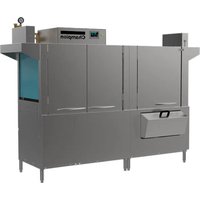
80HD PRO - Dishwasher Champion - Free user manual and instructions
Find the device manual for free 80HD PRO Champion in PDF.


| Product Type | Dishwasher |
| Model | 80HD PRO |
| Brand | Champion |
| Dimensions (H x W x D) | 850 x 600 x 600 mm |
| Weight | 45 kg |
| Power Supply | 220-240 V, 50 Hz |
| Energy Efficiency Class | A++ |
| Place Settings | 12 |
| Noise Level | 44 dB |
| Number of Programs | 6 |
| Water Consumption per Cycle | 9.5 L |
| Power Consumption per Cycle | 0.93 kWh |
| Color | White / Silver |
| Control Type | Electronic push buttons |
| Display | LED |
| Delay Start | Up to 24 hours |
| Safety Features | Child lock, overflow protection |
| Maintenance | Clean filter monthly, descale every 3 months |
| Key Spare Parts | Filter, spray arms, cutlery basket |
| Repairability | User-replaceable parts available |
Frequently Asked Questions - 80HD PRO Champion
User questions about 80HD PRO Champion
0 question about this device. Answer the ones you know or ask your own.
Ask a new question about this device
Download the instructions for your Dishwasher in PDF format for free! Find your manual 80HD PRO - Champion and take your electronic device back in hand. On this page are published all the documents necessary for the use of your device. 80HD PRO by Champion.
USER MANUAL 80HD PRO Champion
PRO Series
Standard
Rack Conveyor Dishwashers
For machines beginning with S/N RE19038937 and above
National Service Department
In Canada: In the USA:
Toll-free: (800) 263-5798 Toll-free: (800) 858-4477
Tel: (905) 562-4195 Tel: (336) 661-1556
Fax: (905) 562-4618 Fax: (336) 661-1660
email: service@moyerdiebellimited.com email: service@championindustries.com
ATTENTION
The model no., serial no., voltage, Hz and phase are needed to identify your machine and to answer questions.
The machine data plate is located on the right front corner of the lower panel
Please have this information ready if you call for service assistance.
Two ways to REGISTER YOUR PRODUCT and ACTIVATE YOUR WARRANTY.

PRODUCT REGISTRATION BY FAX
COMPLETE THIS FORM AND FAX TO:
(336) 661-1660 in the USA
1-(800) 204-0109 in Canada
PRODUCT REGISTRATION CARD
Model
Serial #
Date of Installation: ____/____/____
Company Name:
Address:
(Street)
State/Province
Zip/Postal
Code
Telephone #: ( ) ____ --- ____
Contact:
Installation Company:
Address:
Telephone #:
Contact:
FAILURE TO REGISTER YOUR PRODUCT MAY VOID YOUR WARRANTY
IMPORTANT
IMPORTANT
Revision History
Specifications are subject to change based on continual product improvement. Equipment owners may request a revised manual, at no charge, by calling 1 (800) 858-4477 in the USA or 1(800) 263-5798 in Canada.
| Revision Date Pages Effectivity | Revised | Serial | Number | Description |
1.20.17 All RP17011002 Released first edition.
6.14.17 11-15 All Revised electrical connections.
8.4.17 6 All Added mechanical DWT valve.
7,9,10 All Revised fuse blocks.
10.19.18 1 RP18071601 Revised placement instructions to include drains.
15 RP18071601 Revised drain install with electric valve.
14 RP18021381 Fig. 17 changed to show new drive mechanism.
4.17.19 5-6 RP19038937 Added Steam connection data to manual.
7.1.19 1,5,7,18 RP19062022 Changed drain valve from P/N 114471 Dependo-
drain to P/N 117014 globe valve.
8.21.19 7 RP19062022 Changed drain connection to 1-1/4"
2.25.20 4 All Updated fill connection photograph
14 All Added ION Water Conditioner
16 RP20012488 Added continual drive clutch assembly
Limited Warranty
LIMITED WARRANTY
Champion Industries (herein referred to as "The Company"), 3765 Champion Blvd., Winston-Salem, North Carolina 27105, and 2674 N. Service Road, Jordan Station, Ontario, Canada, L0R 1S0, warrants machines, and parts, as set out below.
Warranty of Machines: The Company warrants all new machines of its manufacture bearing the name "Champion and installed within the United States and Canada to be free from defects in material and workmanship for a period of one (1) year after the date of installation or fifteen (15) months after the date of shipment by The Company, whichever occurs first. [See below for special provisions relating to glasswashers.] Warranty registration must be submitted to The Company within ten (10) days after installation either online on the Champion Industries website or by the fax form provided at the front of this manual. The Company will not assume any responsibility for extra costs for installation in any area where there are jurisdictional problems with local trades or unions.
If a defect in workmanship or material is found to exist within the warranty period, The Company, at its election, will either repair or replace the defective part or accept return of the machine for full credit; provided; however, as to glasswashers, The Company's obligation with respect to labor associated with any repairs shall end (a) 120 days after shipment, or (b) 90 days after installation, whichever occurs first. In the event that The Company elects to repair, the labor and work to be performed in connection with the warranty shall be done during regular working hours by a Champion authorized service technician. Defective parts become the property of The Company. Use of replacement parts not authorized by The Company will relieve The Company of all further liability in connection with its warranty. In no event will The Company's warranty obligation exceed The Company's charge for the machine. The following are not covered by The Company's warranty:
a. Lighting of gas pilots or burners.
b. Cleaning of gas lines.
c. Replacement of fuses or resetting of overload breakers.
d. Adjustment of thermostats.
e. Adjustment of clutches.
f. Opening or closing of utility supply valves or switching of electrical supply current.
g. Cleaning of valves, strainers, screens, nozzles, or spray pipes.
h. Performance of regular maintenance and cleaning as outlined in the operator's guide.
i. Damages resulting from water conditions, accidents, alterations, improper use, abuse, tampering, improper installation, or failure to follow maintenance and operation procedures.
j. Wear on Pulper cutter blocks, pulse vanes, and auger brush.
Examples of the defects not covered by warranty include, but are not limited to: (1) Damage to the exterior or interior finish as a result of the above, (2) Use with utility service other than that designated on the rating plate,
(3) Improper connection to utility service, (4) Inadequate or excessive water pressure, (5) Corrosion from chemicals dispensed in excess of recommended concentrations, (6) Failure of electrical components due to connection of chemical dispensing equipment installed by others, (7) Leaks or damage resulting from such leaks caused by the installer, including those at machine table connections or by connection of chemical dispensing equipment installed by others, (8) Failure to comply with local building codes, (9) Damage caused by labor dispute.
Warranty of Parts: The Company warrants all new machine parts produced or authorized by The Company to be free from defects in material and workmanship for a period of 90 days from date of invoice. If any defect in material and workmanship is found to exist within the warranty period The Company will replace the defective part without charge.
DISCLAIMER OF WARRANTIES AND LIMITATIONS OF LIABILITY. THE COMPANY'S WARRANTY IS ONLY TO THE EXTENT REFLECTED ABOVE. THE COMPANY'S MAKE NO OTHER WARRANTIES, EXPRESS OR IMPLIED, INCLUDING, BUT NOT LIMITED, TO ANY WARRANTY OF MERCHANTABILITY, OR FITNESS OF PURPOSE. THE COMPANY SHALL NOT BE LIABLE FOR INCIDENTAL OR CONSEQUENTIAL DAMAGES. THE REMEDIES SET OUT ABOVE ARE THE EXCLUSIVE REMEDIES FOR ANY DEFECTS FOUND TO EXIST IN THE COMPANY'S' DISHWASHING MACHINES AND THE COMPANY'S PARTS, AND ALL OTHER REMEDIES ARE EXCLUDED, INCLUDING ANY LIABILITY FOR INCIDENTALS OR CONSEQUENTIAL DAMAGES.
The Company does not authorize any other person, including persons who deal in Champion dishwashing machines to change this warranty or create any other obligation in connection with Champion dishwashing machines.
Table of Contents
Revision History......i
Limited Warranty....ii
Model Descriptions iv
Installation....1
Receiving and Placement ....1
Installation Codes/Safety Symbols 2
Table Connections....3
Hot Water Connection ....4
Steam Connection 5
Drain Connection 7
Cold Water Connection for Drain Water Tempering Valve 8
Ventilation - Vent Hood Fan Control 9
Ventilation - Pant Leg Duct Settings 10
Detergent Dispenser Connection 11
Rinse-aid Dispenser Connection ....12
Electrical Connections....14
Change 1-Point to 2-Point Electrical Connection ....15
Check Motor Rotation 16
21kW to 12kW Booster Conversion....17
Model Descriptions
| 44 PRO 44" single tank |
| 66 PRO 44" single tank with 22" prewash |
| 70FF PRO 44" single tank with front feed 26" prewash |
| 80FF PRO 44" single tank with 36" heavy duty prewash |
Receiving

- Inspect the machine for damage and immediately report the damage to a supervisor.
- Check the inside of the machine for accessories and installation parts.
- Register your machine by fax or online as soon as possible.

WARNING:
Use extreme caution to prevent damage to the machine when removing from pallet.
Placement
- Check the dishwasher interior for curtains, panels and supplies.
- Lift the dishwasher off the shipping pallet and move the machine near its permanent location.
- Adjust the height and level of the machine using the adjustable legs. Level the machine from side-to-side and front-to-back.
- Do not remove tags attached to the utility connections.
- Remove the protective film from the dishwasher exterior.

Fig. 1

NOTE:
DO NOT REMOVE THE INSTALLATION TAGS ATTACHED TO THE MACHINE UNTIL ALL UTILITIES ARE CONNECTED.
Installation
Installation Codes
The installation of the dishwasher must comply with all local electrical, plumbing, health and safety codes or in the absence of local codes, installed in accordance with the applicable requirements in the National Electrical Code, NFPA 70, Canadian Electrical Code (CEC), Part 1, CSA C22.1; and the Standard for Ventilation Control and Fire Protection of Commercial Cooking Operations, NFPA 96.

NOTE:
Only qualified personnel familiar with the installation of food service equipment should attempt the installation of this machine. Damage or problems associated with improper installation will not be covered by the dishwasher limited warranty.
Safety Symbols
The following symbols are used throughout this manual to alert the reader to important information.

WARNING:
Warning statements indicate a condition or practice that can result in personal injury or possible death.

CAUTION:
Caution statements indicate a condition or practice that can result in damage to the
machine or associated equipment.

NOTE:
Note statements highlight important information necessary for the operation of the
machine.
Table Connections

NOTE:
Tables should be installed after the machine is placed in its final location, properly leveled and its height properly adjusted. The standard load height for the dishwasher is 34" [864 mm].
When installing the dish tables:
- The load end table must slope away from the dishwasher to prevent water from entering the machine. The unload table should slope toward the machine to prevent water from pooling on the exit table.
- The dish rack must not hit the end of the table as it enters or exits the machine. Adjust the table until the track height of the machine is approximately 1/4" above the table edge.
- Set the tables inside the machine making sure the table flange fits against the wash tank wall. Attach the tables to the machine applying a silicone sealant to the mating surfaces. See Fig. 4.
![25" [635] Machine Width 21-3/4" [552] Opening 20" [508] Inside Track 34" [864] Load Ht.](/content/2026/07/1429487/images/c44953fd40402cc19076f56d020b45dc1690e96013fa6fe47dcf97180a3f7d05.jpg)
Fig. 2 - Load Height

Fig. 3 - Suggested Table Construction

Fig. 4 - Attaching the Tables
Hot Water Connection


Connect the plumbing in accordance with the specifications below.

MINIMUM 1/2" NPT HOT WATER SUPPLY LINE.

CAUTION: To prevent damage to the dishwasher supply valves, the installing plumber must thoroughly flush debris from the water supply line before connecting it to the dishwasher. Damage caused by improper installation is not covered by the limited warranty.
![graph LR A["BOOSTER RISE °F"] --> B["40°F RISE"] B --> C["12kW"] C --> D["140°F/60°C"] D --> E["45 PSI/310 kPa"] E --> F["20/22 PSI 138-152 kPa"] G["BOOSTER RISE"] --> H["70°F RISE"] H --> I["21kW"] I --> J["110°F/ 43°C"] J --> K["45 PSI/310 kPa"] K --> L["20/22 PSI 138-152 kPa"] M["NO BOOSTER"] -->…](/content/2026/07/1429487/images/fbd4b0261d68c87e783bbf5ad4013b7638105db8f00a9c551a81465bcad00774.jpg)

ATER HARDNESS OF 3 GRAINS/US GAL - 0.83 IMP GAL -5.3mg/L or LESS.

STALL A 1/2" OR LARGER SHUT-OFF VALVE IN THE WATER SUPPLY LINE CLOSE TO THE DISHWASHER AS POSSIBLE FOR SERVICING.

ATER SUPPLY CONNECTION IS LOCATED AT THE TOP OF THE MACHINE, AND ALWAYS ON THE UNLOAD SIDE.

STALL A PRESSURE REGULATING VALVE IN THE INCOMING WATER PPLY LINE TO MAINTAIN THE PROPER FLOWING PRESSURE.

Fig. 5
Steam Connections



CAUTION: The dishwasher steam connections must comply with all local plumbing, health and safety codes. Damage caused by improper installation is not covered by the limited warranty
CHECK THE STEAM SUPPLY PRESSURE REQUIREMENTS PRIOR TO CONNECTING THE STEAM SUPPLY LINES.
STANDARD REQUIRED STEAM SUPPLY PRESSURE IS 10-30 PSI.
NIMUM 1-1/4" NPT STEAM LINE.
S EAM CONNECTION IS ALWAYS LOCATED AT THE RIGHT SIDE OF THE MACHINE.
CONDENSATE LINES MUST BE GRAVITY DRAIN WITH NO BACK PRESSURE. CONDENSATE LIFT PUMP MUST BE INSTALLED IF THE CONDENSATE IS ABOVE THE FINISHED FLOOR.
Steam Heating
! NK HEAT: lbs./hr. required at 15 PSI = 75
!EAM BOOSTER: lbs./hr. required 40°F Rise AT 15 PSI = 60
EAM BOOSTER: lbs./hr. required 70°F AT 15 PSI = 85
ITER HARDNESS OF 3 GRAINS/US GAL - 0.83 IMP GAL -5.3mg/L or LESS.
This Page Intentionally Left Blank
Drain Connection


Connect the drain in accordance with the specifications below.
GRAVITY DRAIN- 1-1/4" NPT DRAIN CONNECTION LOCATED UNDERNEATH MACHINE. MAX FLOW IS 17 US GAL/MIN.
USE A DIRECT OR INDIRECT CONNECTION TO THE BUILDING DRAIN IN ACCORDANCE WITH LOCAL CODE.
FOR PREWASH MACHINES, CONNECTION IS AT THE LOAD END.
FOR SINGLE TANK MACHINES, THE CONNECTION IS AT THE RIGHT-HAND SIDE OF THE MACHINE UNDER THE BOOSTER.
THE DRAIN VALVE(S) ARE ELECTRIC. THEY OPEN AND CLOSE AUTOMATICALLY WHEN DISHWASHER POWER IS OFF OR ON.
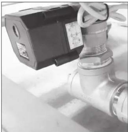
Fig. 6B - Electric Drain Valve

Fig. 6A - Drain connections.

NOTE: Procedure to manually open and close the valve on page 18.
Installation
Cold Water Connection Drain Water Tempering, (DWT), Valve



IMUM 1/2" NPT COLD WATER SUPPLY LINE.
MINIMUM INCOMING WATER TEMPERATURE
MAXIMUM INCOMING SUPPLY PRESSURE
36° F / 2° C
60 PSI/414 kPa

CAUTION: To prevent damage to the dishwasher supply valves, the installing plumber must thoroughly flush debris from the water supply line before connecting it to the dishwasher. Damage caused by improper installation is not covered by the limited warranty.

TER HARDNESS OF 3 GRAINS/US GAL - 0.83 IMP GAL -5.3mg/L or LESS.

TALL A 1/2" OR LARGER SHUT-OFF VALVE IN THE WATER SUPPLY LINE CLOSE TO THE DISHWASHER AS POSSIBLE FOR SERVICING.

TER SUPPLY CONNECTION IS LOCATED NEAR A MACHINE CORNER THE BASE OF THE DISHWASHER.

NNECT A 1/2" NPT DRAIN LINE TO THE MECHANICAL DWT DEVICE (Fig. 7a).
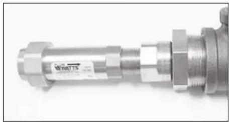
Fig. 7a - Mechanical DWT Valve
ION Water Conditioner
CONNECT A 1/2" NPT HOT WATER SUPPLY LINE TO THE INSTALLED

I WATER CONDITIONER. (SEE CTORY FOR PROPER SIZE.
THE MECHANICAL DWT DEVICE (Fig. 7a).
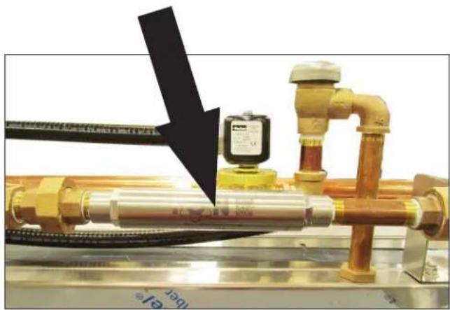
Fig. 7b - Icon Water Conditioner Installed
Ventilation - Vent Hood Fan Control

Standard model installations using an approved vent hood may require a vent fan signal. This signal is supplied by the dishwasher control circuit. A qualified installer must connect a signal circuit to the fuse holder and a common neutral terminal provided. See Fig. 8.

CAUTION: To prevent damage to the dishwasher do not connect vent fan motor to the Line Power 120VAC, 0.5 Amp fused connection terminals. Damage to any component caused by improper installation is not covered by the limited warranty.
The fused 120VAC Line Power only supplies an external vent fan contactor (supplied by others), and is limited to 0.5 AMP maximum load. The 120VAC is powered whenever main power is on.
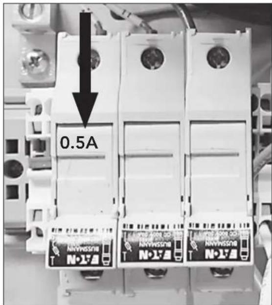
Fig. 8 - Connection is located inside the top control cabinet.
Continued on next page.
Installation
Ventilation - Pant Leg Duct Settings

LOAD END 200 CFM @ 1/4"SP/71 L/SEC UNLOAD END 400 CFM @ 1/4" SP/189 L/SEC.
NIMUM OF SIX KITCHEN AIR CHANGES PER HOUR RECOMMENDED.
TWO 4' X 16" VENT STACKS WITH ADJUSTABLE DAMPERS ARE APPLIED WITH THE MACHINE.

NOTE:
Loosen the wing-nut holding the damper handle and turn it to open or close the damper and adjust the steam exiting the machine.

Fig. 9 - Vent
Detergent Dispenser Connection

! NASH TANK CAPACITY IS 17 US GAL./14.2 IMP. GAL/64.4 L.
WE A NON-CHLORINATED COMMERCIAL GRADE DETERGENT.
23" DIAMETER HOLES ARE PROVIDED IN THE TANK.
i USED 120VAC 0.5 AMP MAX LOAD DETERGENT SIGNAL CONNECTION IS PROVIDED INSIDE THE CONTROL CABINET.
!E DETERGENT SIGNAL IS ENABLED THROUGHOUT THE WASH CYCLE.
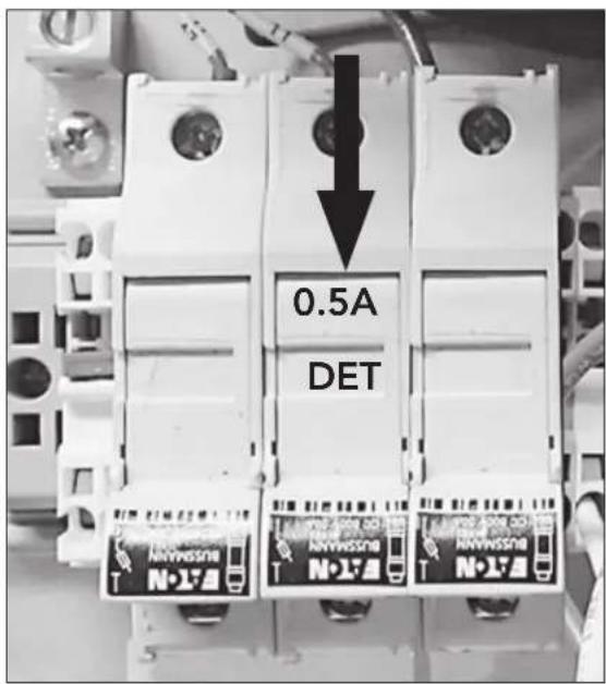
Fig. 10 - Connection is located inside the top control cabinet.
Rinse-Aid Dispenser Connection


RINSE

0.48 US GAL/RACK, 0.40 IMP. GAL/RACK, 1.82
L/RACK

NPT PIPE PLUG PROVIDED IN FINAL RINSE PIPING.

SED 120VAC 0.5 AMP MAX LOAD RINSE AID SIGNAL NNECTION IS PROVIDED INSIDE THE CONTROL CABINET.

Fig. 11 Rinse Aid Connection

Electrical Connections

The installation of the dishwasher must comply with all local electrical, plumbing, health and safety codes or in the absence of local codes, installed in accordance with the applicable requirements in the National Electrical Code, NFPA 70, Canadian Electrical Code (CEC), Part 1, CSA C22.1; and the Standard for Ventilation Control and Fire Protection of Commercial Cooking Operations, NFPA 96.

CAUTION:
Only qualified personnel familiar with the installation of food service equipment should attempt the installation of this machine. Damage or problems associated with improper installation will not be covered by the dishwasher limited warranty.

WARNING:
There may be more than one power source connected to the machine. Make sure all power sources are disconnected, locked and tagged out before working on the machine.
Electrocution may occur when working on energized circuits. Disconnect power at the main breaker or service disconnect switch, then lock out and tag it to indicate that work is being performed on the circuit.
! ATTENTION INSTALLER !
All machines are shipped from the factory as a 1-POINT connection. The BOOSTER is wired for 21kW operation.
IT IS THE INSTALLER'S RESPONSIBILITY TO CHANGE THE CONNECTION TO 2-POINT AND/OR THE BOOSTER TO 12kW IF REQUIRED.
Electrical Connections - Change 1-Point to 2-Point Electrical Connection
COMPARE THE ELECTRICAL SUPPLY WITH THE MACHINE ELECTRICAL
# CONNECTION DATA PLATE BEFORE CONNECTING THE POWER TO THE MACHINE.
THE DATA PLATE IS ADJACENT TO THE INPUT TERMINAL BLOCKS.
POINT CONNECTION MACHINES HAVE JUMPERS BETWEEN THE INPUT BLOCKS.
REMOVE THE JUMPERS FOR 2-POINT ELECTRICAL CONNECTION.
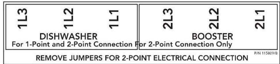
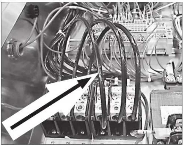
Fig.12 - 1-point connection jumpers.
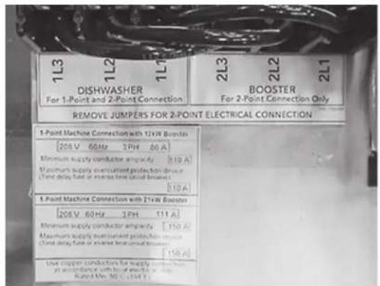
Fig.13 - 1-point connection data plate
To convert a 1-point connection machine to a 2-point connection machine.
-
Open the control cabinet and remove the jumpers, (Fig. 12), between 'Dishwasher' terminal block and the 'Booster' terminal block.
-
Cover the existing 1-point connection data plate, (Fig. 13), with the 2-point connection data plate, (Fig. 14), stowed in the plastic bag, (Fig. 15), next to the input terminal block.
-
Connect the incoming power according to the customer's requirements.
-
Conversion is complete
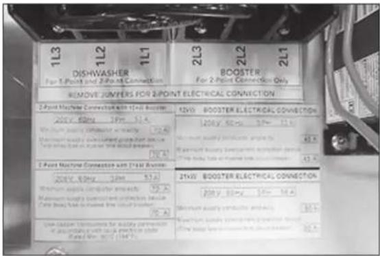
Fig.14 - 2-point connection data plate

Fig.15 -
The 2-point data plate is located in a plastic bag next to the terminal block.
Installation

Electrical Connections - Check Motor Rotation and Drive Clutch Settings
All motors are phased the same at the factory. Reverse L1 and L2 at the main terminal block to change motor direction of all motors.
- Fig. 16 shows the rotation arrow label on the rear pump housing.
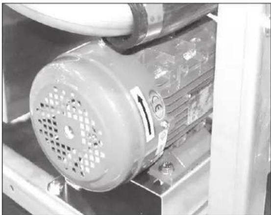
Fig. 16
- Fig. 17 shows the clutch drive mechanism with the rotation label to indicate rotation.


Fig. 17
Electrical Connections- 21 kW to 12kW Booster Conversion

ATTENTION
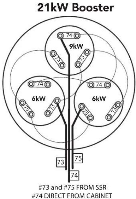
The booster is shipped from the factory wired for 21kW operation. For 12kW operation, the booster must be reconnected as shown below.
21kW to 12kW Booster Conversion
1 Disconnect all power from the unit.
2 Remove the booster cover.
3 Remove the jumper wires from the 9kW element.
4 Connect a jumper wire between 73 on the 6kW elements.
5 Remove the power wire #74 from the 9kw element.
6 Reconnect the power wire #74 to the #74 strap on the left 6kW element.
7 Double-check all wiring.
8 Replace the booster cover.
9 Conversion is complete.

HOW TO MANUALLY OPERATE NEW PRO DRAIN VALVE
Electric Drain Valve, P/N 117014 Beginning with S/N: RP19062022, Effective 7/1/19
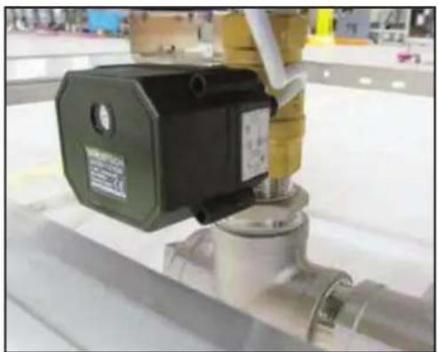
- The new electric drain valve does not have a manual lever as the Dependo-Drain.
- To manually operate the new valve, four 2.5mm socket allen screws must be removed, the valve coil removed, and the valve globe rotated with pliers.
- The valve coil has an indicator line showing valve position. Ensure valve is reassembled in the same position.

1
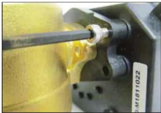
Remove four 2.5mm coil retaining allen screws.
2

Remove the coil from the valve body.
3

Using pliers, turn the valve body key to the vertical position to open valve.
Reassemble in reverse order.

- NATIONAL SERVICE DEPARTMENT
- ATTENTION
- TWO WAYS TO REGISTER YOUR PRODUCT AND ACTIVATE YOUR WARRANTY
- PRODUCT REGISTRATION BY FAX
- PRODUCT REGISTRATION CARD
- REVISION HISTORY
- LIMITED WARRANTY
- TABLE OF CONTENTS
- INSTALLATION....1
- MODEL DESCRIPTIONS
- RECEIVING
- WARNING
- PLACEMENT
- NOTE
- INSTALLATION
- INSTALLATION CODES
- SAFETY SYMBOLS
- CAUTION
- TABLE CONNECTIONS
- HOT WATER CONNECTION
- STEAM CONNECTIONS
- STEAM HEATING
- EAM BOOSTER: LBS./HR. REQUIRED 70°F AT 15 PSI = 85
- THIS PAGE INTENTIONALLY LEFT BLANK
- DRAIN CONNECTION
- COLD WATER CONNECTION DRAIN WATER TEMPERING, (DWT), VALVE
- ION WATER CONDITIONER
- VENTILATION - VENT HOOD FAN CONTROL
- VENTILATION - PANT LEG DUCT SETTINGS
- DETERGENT DISPENSER CONNECTION
- RINSE-AID DISPENSER CONNECTION
- ELECTRICAL CONNECTIONS
- ATTENTION INSTALLER
- ELECTRICAL CONNECTIONS - CHANGE 1-POINT TO 2-POINT ELECTRICAL CONNECTION
- ELECTRICAL CONNECTIONS - CHECK MOTOR ROTATION AND DRIVE CLUTCH SETTINGS
- ELECTRICAL CONNECTIONS- 21 KW TO 12KW BOOSTER CONVERSION
- 21KW TO 12KW BOOSTER CONVERSION
- HOW TO MANUALLY OPERATE NEW PRO DRAIN VALVE
- 1
- 2
- 3
Brand : Champion
Model : 80HD PRO
Category : Dishwasher