
AV2X - LED Screen Adj - Free user manual and instructions
Find the device manual for free AV2X Adj in PDF.


| Product Type | LED Lighting Fixture |
| Model | AV2X |
| Brand | Adj |
| Dimensions (L x W x H) | 12 x 8 x 6 inches |
| Weight | 2.5 lbs |
| Power Supply | AC 100-240V, 50/60Hz |
| Power Consumption | 30W |
| Light Source | LED (RGBW) |
| Beam Angle | 25° |
| Control Protocol | DMX512 |
| DMX Channels | 4/8 selectable |
| Operating Modes | Standalone, Master/Slave, Sound Active |
| Housing Material | Aluminum alloy |
| IP Rating | IP20 |
| Cooling | Passive convection |
| Maintenance | Clean lens with soft dry cloth; avoid solvents |
| Safety | CE, RoHS compliant; keep away from moisture |
| Spare Parts | Contact Adj support for replacement LEDs or power supply |
| Repairability | User replaceable fuse; others require technician |
| Warranty | 2 years limited |
Frequently Asked Questions - AV2X Adj
User questions about AV2X Adj
0 question about this device. Answer the ones you know or ask your own.
Ask a new question about this device
Download the instructions for your LED Screen in PDF format for free! Find your manual AV2X - Adj and take your electronic device back in hand. On this page are published all the documents necessary for the use of your device. AV2X by Adj.
USER MANUAL AV2X Adj

©2020 ADJ PRODUCTS LLC all rights reserved. Information, specifications, diagrams, images, and instructions herein are subject to change without notice. ADJ logo and identifying product names and numbers herein are trademarks of ADJ PRODUCTS LLC. Copyright protection claimed includes all forms and matters of copyrightable materials and in- formation now allowed by statutory or judicial law or hereinafter granted. Product names used in this document may be trademarks or registered trademarks of their respective companies and are hereby acknowledged. All non-ADJ brands and product names are trademarks or registered trademarks of their respective companies.
ADJ PRODUCTS LLC and all affiliated companies hereby disclaim any and all liabilities for property, equipment, building, and electrical damages, injuries to any persons, and direct or indirect economic loss associated with the use or reliance of any information contained within this document, and/or as a result of the improper, unsafe, insufficient and negligent assembly, installation, rigging, and operation of this product.
ADJ PRODUCTS LLC USA
6122 S. Eastern Ave. Los Angeles, CA 90040
323-582-2650 | Fax 323-532-2941 | www.adj.com | info@adj.com
ADJ SUPPLY Europe B.V
Junostraat 2 6468 EW Kerkrade, The Netherlands
+31 (0)45 546 85 00 | Fax +31 45 546 85 99 | www.adj.eu | info@americandj.eu
ADJ PRODUCTS GROUP Mexico
AV Santa Ana 30 Parque Industrial Lerma, Lerma, Mexico 52000
+52 (728) 282-7070 | ventas@adj.com
FCC STATEMENT
This device complies with Part 15 of the FCC Rules. Operation is subject to the following two conditions: (1) this device may not cause harmful interference, and (2) this device must accept any interference received, including interference that may cause undesired operation.
FCC RADIO FREQUENCY INTERFERENCE WARNINGS & INSTRUCTIONS
This product has been tested and found to comply with the limits as per Part 15 of the FCC Rules. These limits are designed to provide reasonable protection against harmful interference in a residential installation. This device uses and can radiate radio frequency energy and, if not installed and used in accordance with the included instructions, may cause harmful interference to radio communications. However, there is no guarantee that interference will not occur in a particular installation. If this device does cause harmful interference to radio or television reception, which can be deter- mined by turning the device off and on, the user is encouraged to try to correct the interference by one or more of the following methods:
- Reorient or relocate the device.
- Increase the separation between the device and the receiver.
- Connect the device to an electrical outlet on a circuit different from which the radio receiver is connected. Consult the dealer or an experienced radio/TV technician for help.
Energy Saving Matters (EuP 2009/125/EC)
Saving electric energy is a key to help protecting the environment. Please turn off all electrical products when they are not in use. To avoid power consumption in idle mode, disconnect all electrical equipment from power when not in use. Thank you!
Document Version: An updated version of this document may be available online. Please check www.adj.com for the latest revision/update of this document before beginning installation and use.
| Date | Document Version | Notes |
| 05/13/19 | 1 | Initial release |
| 11/26/19 | 1.5 | Update specifications |
| 03/03/20 | 2.0 | Update Optional Components & Accessories |
CONTENTS
| General Information | 4 |
| Limited Warranty (USA Only) | 5 |
| Safety Guidelines | 6 |
| Maintenance Guidelines | 8 |
| Panel Overview | 9 |
| Handling and Transportation | 11 |
| Installation | 13 |
| Technical Specifications | 21 |
| Optional Components and Accessories | 22 |
GENERAL INFORMATION
With a brightness of 1000 NITS and a 2.97mm pixel pitch, the AV2X is a cost effective, bright, high-resolution video panel designed for indoor use. Although the 3-in-1 RGB SMD2121 LEDs create an impressive brightness of 1000 NITS, with its 0-100% adjustable brightness, the intensity of the screen can be reduced for all indoor applications. The 2.97mm pixel pitch translates to 168 x 168 LEDs, equivalent to 112,896 dot/m2, with a wide viewing angle of 160°. Each AV2X LED Video Panel is composed of 4 modular LED panels, which allows for easier serviceability. Additionally, the AV2X LED Video Panels can connect horizontally for curved-in or curved-out screen surfaces (convex/concave ±5°).
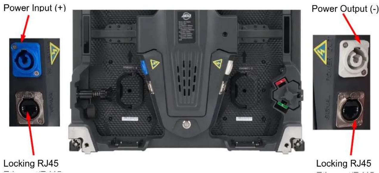
With multiple panels linked to mains power, the AV2X LED video panel has a maximum power consumption of 115W per panel, an average consumption of 35W per panel, and each panel is fitted with a Locking Power Connector input and output socket allowing the power supply for multiple panels to be linked. Locking RJ45 Ethernet input and output sockets are also provided for each panel, allowing the signal data to daisy-chain across each panel to make up a larger screen. Using ADJ's range of video processors with the internal 14-bit NovaStar data receiving card, multiple panels can be linked using standard Ethernet cables.
ADJ offers a number of video processors that can be used to convert a standard video signal (HDMI, DVI, VGA etc.) for use with the AV Series LED panels. These processors range from the basic and cost effective MCTRL-300 that can drive up to 1.3 million pixels (up to 11 AV2X panels,), to the advanced Novastar VX4S that can drive up to 2.6 million pixels (up to 23 AV2X panels) with multiple cascades to create unlimited size screens.
The AV2X is a great video solution for your show, and ADJ offers full packages with video processors, software, cabling, rigging bars, and flight cases so that you have everything you need to get up and running.
LIMITED WARRANTY
A. ADJ Products, LLC hereby warrants, to the original purchaser, ADJ Products, LLC products to be free of manufacturing defects in material and workmanship for a prescribed period from the date of purchase (see specific warranty period on reverse). This warranty shall be valid only if the product is purchased within the United States of America, including possessions and territories. It is the owner's responsibility to establish the date and place of purchase by acceptable evidence, at the time service is sought.
B. For warranty service, you must obtain a Return Authorization number (RA#) before sending the product back—please contact ADJ Products, LLC Service Department at 800-322-6337. Send the product only to the ADJ Products, LLC factory. All shipping charges must be prepaid. If the requested repairs or service (including parts replacement) are within the terms of this warranty, ADJ Products, LLC will pay return shipping charges only to a designated point within the United States. If the entire instrument is sent, it must be shipped in its original package and packaging material. No accessories should be shipped with the product. If any accessories are shipped with the product, ADJ Products, LLC shall incur no liability whatsoever for loss of or damage to any such accessories, nor for the safe return thereof.
C. This warranty is void if the product serial number and/or labels are altered or removed; if the product is modified in any manner which ADJ Products, LLC concludes, after inspection, affects the reliability of the product; if the product has been repaired or serviced by anyone other than the ADJ Products, LLC factory unless prior written authorization was issued to purchaser by ADJ Products, LLC; if the product is damaged because it was not properly maintained as set forth in the product instructions, guidelines and/or user manual.
D. This is not a service contract, and this warranty does not include maintenance, cleaning, or periodic checkup. During the period specified above, ADJ Products, LLC will replace defective parts at its expense with new or refurbished parts, and will absorb all expenses for warranty service and repair labor by reason of defects in material or workmanship. The sole responsibility of ADJ Products, LLC under this warranty shall be limited to the repair of the product, or replacement thereof, including parts, at the sole discretion of ADJ Products, LLC. All products covered by this warranty were manufactured after August 15, 2012, and bear identifying marks to that effect.
E. ADJ Products, LLC reserves the right to make changes in design and/or improvements upon its products without any obligation to include these changes in any products theretofore manufactured.
F. No warranty, whether expressed or implied, is given or made with respect to any accessory supplied with products described above. Except to the extent prohibited by applicable law, all implied warranties made by ADJ Products, LLC in connection with this product, including warranties of merchantability or fitness, are limited in duration to the warranty period set forth above. And all warranties, whether expressed or implied, including warranties of merchantability or fitness, are limited in duration to the warranty period set forth above. The consumer's and/or dealer's sole remedy shall be such repair or replacement as is expressly provided above; and under no circumstances shall ADJ Product, LLC be liable for any loss and/or damage, direct and/or consequential arising out of the use of, and/or inability to use this product.
G. This warranty is the only written warranty applicable to ADJ Products, LLC products, and supersedes all prior warranties and written descriptions of warranty terms and conditions heretofore published.
MANUFACTURER'S LIMITED WARRANTY PERIODS:
Non-LED Lighting Products = 1-Year (365 Days) (Including Special Effect Lighting, Intelligent Lighting, UV lighting, Strobes, Fog Machines, Bubble Machines, Mirror Balls, Par Cans, Trussing, Lighting Stands, Power/Data Distribution, etc. excluding LED and lamps)
Laser Products = 1-Year (365 Days) (excluding laser diodes which have a 6-Month Limited Warranty)
LED Products = 2-Year (730 Days) (excluding batteries which have a 180 Day Limited Warranty)
NOTE: 2-Year (730 Days) Limited Warranty ONLY applies to product purchased within the United States.
StarTec Series = 1-Year (365 Days) (excluding batteries which have a 180 Day Limited Warranty)
ADJ DMX Controllers = 2 Year (730 Days)
American Audio Products = 1 Year (365 Days)
CUSTOMER SUPPORT INFORMATION
Contact ADJ Service for any product related service and support needs.
Also visit forums.adj.com with questions, comments or suggestions.
ADJ SERVICE USA - Monday - Friday 8:00am to 4:30pm PST
323-582-2650 | Fax: 323-832-2941 | support@adj.com
ADJ SERVICE EUROPE - Monday - Friday 08:30 to 17:00 CET
+31 45 546 85 60 | Fax: +31 45 546 85 96 | support@adj.eu
SAFETY GUIDELINES
This panel is a sophisticated piece of electronic equipment. To guarantee a smooth operation, it is important to follow all instructions and guidelines in this manual. ADJ is not responsible for injury and/or damages resulting from the misuse of this panel due to the disregard of the information printed in this manual. Only qualified and/or certified personnel should perform the installation of this panel and all included and/or rigging accessories. Only the original included rigging parts and/or rigging accessories for this panel should be used for proper installation. Any modifications to the panel, included and/or rigging accessories will void the original manufactures warranty and increase the risk of damage and/or personal injury.

PROTECTION CLASS 1 - PANEL MUST BE PROPERLY GROUNDED
THERE ARE NO USER SERVICEABLE PARTS INSIDE THIS PANEL.

DO NOT ATTEMPT ANY REPAIRS YOURSELF; DOING SO WILL VOID YOUR MANUFACTURES WARRANTY. DAMAGES RESULTING FROM MODIFICATIONS TO THIS PANEL AND/OR THE DISREGARD OF SAFETY INSTRUCTIONS AND GUIDELINES IN THIS MANUAL VOID THE MANUFACTURES WARRANTY AND ARE NOT SUBJECT TO ANY WARRANTY CLAIMS AND/OR REPAIRS. DO NOT PLUG PANEL INTO A DIMMER PACK! NEVER OPEN THIS PANEL WHILE IN USE! UNPLUG POWER BEFORE SERVICING PANEL! NEVER TOUCH FRONT OF PANEL DURING OPERATION, AS IT MAY BE HOT! KEEP FLAMMABLE MATERIALS AWAY FROM PANEL.

INDOOR / DRY LOCATIONS USE ONLY! DO NOT EXPOSE PANEL TO RAIN AND/OR MOISTURE! DO NOT SPILL WATER AND/OR LIQUIDS ON OR INTO THE PANEL!
DO NOT touch panel housing during operation. Turn OFF power and allow approximately 15 minutes for panel to cool down before serving.
DO NOT: Operate a panel if any cover is open and/or removed.
DO NOT shake panel, avoid brute force when installing and/or operating panel.
DO NOT: Expose any part of the panel to open flame or smoke. Keep panel away from heat sources such as radiators, heat registers, stoves, or other appliances (including amplifiers) that produce heat.
DO NOT: Install/use panel in extreme hot/humid environments, or handle without ESD precautions.
DO NOT: Exceed an operation temperature of 40° C ( 104° F), doing so will damage the panel.
DO NOT operate panel if power cord is frayed, crimped, damaged and/or if any of the power cord connectors are damaged and do not insert into the panel securely with ease. NEVER force a power cord connector into the panel. If the power cord or any of its connectors are damaged, replace it immediately with a new one of similar power rating.
DO NOT block air ventilation slots/vents. All fan and air inlets must remain clean and never blocked. Allow approximately 6" (15cm) between panel and other devices or a wall for proper cooling.
ALWAYS disconnect panel from main power source before performing any type of service and/or cleaning procedure. Only handle the power cord by the plug end, never pull out the plug by tugging the wire portion of the cord.
SAFETY GUIDELINES
ONLY use the original packaging materials and/or case to transport the panel in for service.
PLEASE recycle shipping boxes and packaging whenever possible.
CAUTION: To avoid physical damage, read the installation instructions carefully before installation.
CAUTION: Panels should only be installed/operated by qualified and trained professionals ONLY.
CAUTION: Always mount panels in a safe and stable manner.
CAUTION: INDOOR / DRY location use ONLY! Outdoor use will void the warranty.
CAUTION: Wear appropriate safety equipment during panel installation.
CAUTION: Turn OFF power to panel, computers, servers, system boxes, and monitors before making any type of power or data connections and performing any maintenance work.
CAUTION: Read user manual carefully to ensure normal operation and lifespan of the panel.
CAUTION: Electronics used in this panel are ESD (Electrostatic Discharge) sensitive. To protect device from ESD, wear a grounded ESD wrist strap or similar grounding device when handling panel.
CAUTION: Panel must be properly grounded before operating. (resistance must be less than 4Ω)
CAUTION: Ensure all power is disconnected from panel before unplugging any data cables from the panel, especially serial line ports.
CAUTION: Route power and data cables so that they are NOT likely to be walked on or pinched.
CAUTION: Air conditioning is required if operating environment temperature exceeds 30° C ( 86° F).
CAUTION: Test panel for 2-hours per week, if not used regularly or for an extended period of time.
CAUTION: Cases used to transport panel must me properly waterproofed for transportation.
MAINTENANCE GUIDELINES
Careful and regular maintenance is necessary to optimize the potential functional lifespan of the AV2X LED Video Panels.
- Read the installation and operation instructions for correct operation of the AV2X LED Video Panels.
- Although the AV2X LED Video Panels are designed and built to withstand some impact forces when installed correctly, take care to avoid impact damage when handling or transporting them, especially corners and edges, which are particularly frangible during transportation.
- The fixture should be serviced by a qualified service technician when:
A. Objects have fallen, or liquid has been spilled into the fixture
B. The fixture has been exposed to rain or water conditions in excess of IP rating parameters (IP20 front and rear)
C. The fixture does not appear to operate normally or exhibits a marked change in performance
D. The fixture has fallen and/or subjected to extreme handling.
- Check each AV2X LED Video Panel for loose screws and other fasteners.
- If the AV2X LED Video Panel installation is fixed or displayed for a lengthy time, regularly inspect all rigging and installation equipment, and replace or repair it as necessary, and during long periods of non-use, disconnect the main power to the unit.
- Use necessary ESD (electrostatic discharge) precautions when handling AV2X LED Video Panels, especially the LED screens, as they are ESD sensitive and easily damaged from ESD exposure.
- The Null Line and Live Line connections from the computer and control system cannot be reversed and should therefore only be connected in original layout order.
- If the GFI (Ground Fault Interrupt) breaker-switch trips often, check the display or replace the power-supply switch.
- When operating the AV2X LED Video Panels, power the computer before powering the LED Video Screens; conversely, when shutting down after operation, turn the LED Video Panels off before turning off the computer. If the PC is turned off first, a high intensity brightness might appear, causing catastrophic failure to those LEDs.
- If while conducting an electrical test a circuit shorts, a breaker-switch trips, wires burn, and or any other abnormality appears, discontinue testing and troubleshoot units to find the problem before continuing with any testing or operation.
- To ensure consistent operation, it might be necessary to learn operating parameters for installation, data recovery, backup, controller settings, and basic data preset modification.
- Regularly check computer for any viruses and remove any irrelevant data.
- Only a qualified technician should operate software system.
- Remove any moisture found inside or outside of any AV2X LED Video Panels before dismantling video installation and returning them to their optional flight cases (sold separately). Ensure flight cases are free of any moisture, using a fan to dry them if necessary, and avoid ESD generating friction when returning AV2X LED Video Panels.
- The AV2X LED Video Panels are designed for indoor use only, within its IP20 rating parameters (front / rear), limit or remove any unit exposed to moisture, condensation, or humidity, and consider using air conditioning where available.
- When not in use, store AV2X LED Video Panels in a dry, well ventilated facility.
PANEL OVERVIEW
Each AV2X LED Video Panel includes a quick-release power supply with 4X receiver card modules, allowing for easy serviceability and simple repairs whilst out on the road. The cover of the power supply box can be secured to protect all internal accessories and components.
Dimensions: 19.75" x 19.75" x 3" (500x500x100mm)

AV2X: Front, Side, & Back View

AV2X: Module
PANEL OVERVIEW

AV2X Overview
HANDLING AND TRANSPORTATION
The corners of the AV2X LED Video Panel are susceptible to damage during handling and transportation. When removing AV2X LED Video Panels from their respective Flight Cases (AV2FC sold separately), and before they are installed, take care to avoid damaging any of the 4 corners.

Because these are ESD sensitive units, use ESD precautions when removing the AV2X LED Video Panels from their flight case (ESD gloves, protective clothing, wrist straps, etc.). In addition to using standard ESD precautions, to reduce static building friction, take care to lift the panels without rubbing the LED panel surface along the foam-covered slots, which can generate static electricity that can damage LEDs on AV2X Panel.
HANDLING AND TRANSPORTATION
The optional AV2FC Flight Case (sold separately) for the AV2X LED video panels holds 8x AV2Xs. The flight case features a full foam lining with slots for each unit. The case is robust, so will completely protect a set of panels on the road. Designed specifically for use with AV2X LED video panels, it is constructed from 9mm plywood and fitted with steel ball corners, aluminum edging, large swivel castors, professional butterfly latches, four sprung handles, and a hinged lid.

AV2FC Flight Case
INSTALLATION

DO NOT INSTALL THE PANEL IF YOU ARE NOT QUALIFIED TO DO SO! INSTALLATION BY QUALIFIED TECHNICIANS ONLY!

INSTALLATIONS SHOULD BE CHECKED BY A QUALIFIED PERSON ONCE A YEAR!

FLAMMABLE MATERIAL WARNING
Keep panel minimum 5.0 feet (1.5m) away from flammable materials and/or pyrotechnics.

ELECTRICAL CONNECTIONS
A qualified electrician should be used for all electrical connections and/or installations.

A MAXIMUM OF 20 panels may be suspended from each other vertically in a curtain.
An unlimited number of panels may be installed horizontally.
(NOTE: Additional processing may be necessary)

USE CAUTION WHEN POWER LINKING MULTIPLE PANELS AS THE POWER CONSUMPTION OF OTHER PANEL MODELS MAY EXCEED THE MAX POWER OUTPUT ON THIS PANEL. CHECK SILK SCREEN FOR MAX AMPS.
| Input Power | AC 100-240VAC, 50/60HZ, 16A Max |
| Output Power | AC 100-240VAC, 50/60Hz, 14.5A Max |
| Max Power Consumption | 120W Max, 48W Average |
WARNING! The safety and suitability of any lifting equipment, installation location/platform, anchoring/rigging/mounting method and hardware, and electrical installation is the sole responsibility of the installer.
Panel(s) and all panel accessories and all anchoring/rigging/mounting hardware MUST be installed following all local, national, and country commercial electrical and construction codes and regulations.
Before rigging/mounting a single panel or multiple interconnected panels to any metal truss/structure, a professional equipment installer MUST be consulted to determine if the metal truss/structure or surface is properly certified to safely hold the combined weight of the panels(s), clamps, cables, and all accessories.
Inspect metal truss/structure visually to ensure it does not flex and/or become deformed due to the weight of the panel(s). Damage caused to panel(s) by mechanical stress is not covered by warranty.
Panel(s) should be installed in areas outside walking paths, seating areas, or away from areas were unauthorized personnel might reach the panel(s) by hand. Access under work area must be blocked.
NEVER stand directly below the panel(s) when rigging, removing or servicing.
OVERHEAD RIGGING
Overhead fixture installation must always be secured with a secondary safety attachment, such as an appropriately rated safety cable. Overhead rigging requires extensive experience, including amongst others calculating working load limits, installation material being used, and periodic safety inspection of all installation material and the fixture. If you lack these qualifications, do not attempt the installation yourself. Improper installation can result in bodily injury and property damage.
INSTALLATION - ASSEMBLY Horizontal Panel Assembly

To select panel surface angle, unlock the adjustable horizontal tab-keyed connector socket by rotating knob counterclockwise.

Rotate assembly to desired panel surface angle and re-insert it.

The horizontal tab-keyed connector is spring loaded.
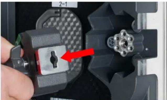
Remove Adjustable horizontal tab-keyed connector socket assembly.

Twist and tighten the knob to the right (clockwise) to lock the horizontal tab-keyed connector assembly.
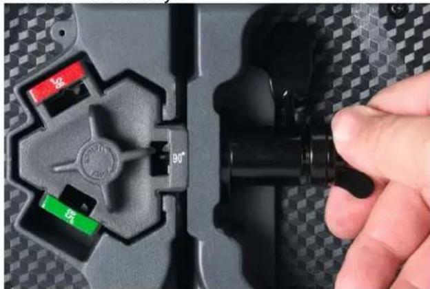
Press the horizontal tab-keyed connector until its tab-key passes through tab-keyed socket.
INSTALLATION - ASSEMBLY
Horizontal Panel Assembly

Rotate the handle to the right (clockwise) to hold the horizontal tab-keyed connector in place.

To unlock, rotate handle (clockwise), releasing tension of horizontal tab-keyed connector cinching mechanism.
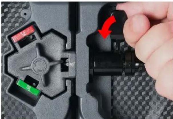
Rotate handle down (counterclockwise) to cinch horizontal tab-keyed connector.
INSTALLATION - ASSEMBLY
Flat, Concave, and Convex Panel Assembly


Use the 85° setting for +5° Convex Screen
Use the 90° setting for Flat Screen
Use the 95° setting for -5° Concave Screen

INSTALLATION - ASSEMBLY Vertical Panel Assembly

Align the vertical positional posts with their corresponding alignment holes.

The vertical connector will snap into place when the latch snaps back to lock connector.

To unlock the vertical connector, rotate lever to the right (counter-clockwise).
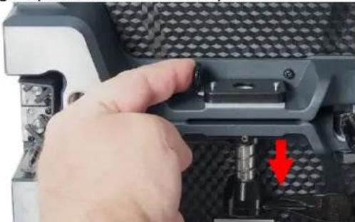
Once latch is released, the vertical connector will snap open.

The vertical tab-keyed connector is spring loaded. Press locking latch lever while pressing vertical key-tabbed connector into matching tab-keyed hole of locking-latch.
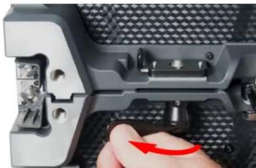
To tighten, twist lever to the left (clockwise).

Press spring-loaded locking socket latch towards the right.
INSTALLATION - ASSEMBLY
Back Panel Bracket

Use an AV2084 Rear Support Bracket (sold separately) when connecting multiple panels for a larger display design, to strengthen the structural integrity of the screen, improve consistent flatness, and improve overall screen continuity.
INSTALLATION - RIGGING
The AV2X is compatible with ADJ's AV2RB1 rigging bar (sold separately), which easily and securely locks to the top of the first panel in a vertical hang of up to 20 AV2Xs, allowing them hang from a truss, hoist, or lintel beam. A qualified technician or trained professional is required to fly the AV2RB1 Rigging Beam/AV2X LED Video Panel assembly.

Note the integrated Vertical Connectors in addition to the Vertical Tab-Keyed Sockets.


Use integrated tabs to secure AV2RB1 Rigging Beam and panels horizontally.

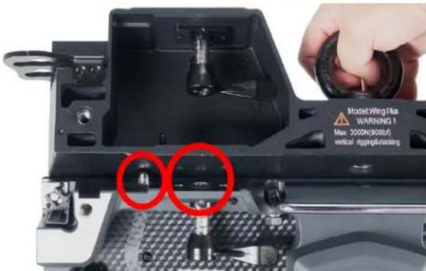
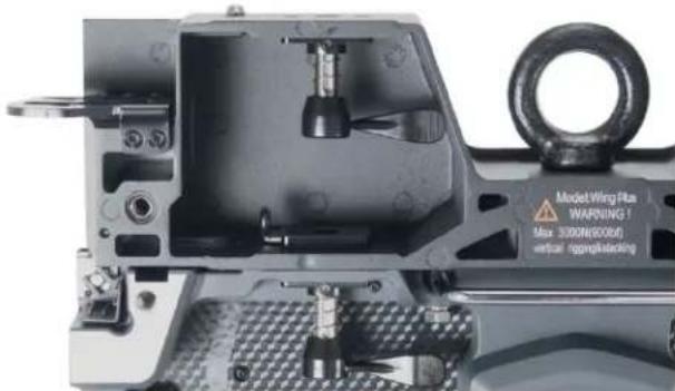
Align the vertical positional posts with their corresponding alignment holes and insert them.


The vertical tab-keyed connector is spring loaded. Press locking latch lever while pressing vertical key-tabbed connector into matching tab-keyed hole of locking-latch, then release latch to lock the vertical connector.
INSTALLATION - RIGGING

To tighten, twist lever to the left (clockwise)

To unlock the vertical connector, rotate lever to the right (counter-clockwise)


Press spring-loaded locking socket latch towards the right; the vertical connector will snap open as soon as the latch is released
TECHNICAL SPECIFICATIONS
| Items | Specifications & Metrics | |
| Panel | LED Configuration | 3-in-1 SMD2121 LED |
| Pixel Pitch | 2.97mm | |
| Panel Resolution (W x H) | 168 x 168 | |
| Pixel Density | 113,367 per square meter | |
| Panel Size (mm) | 19.75" x 19.75" x 3" (500mm x 500mm x 73mm) | |
| Weight (Panel) | 17.64lbs. (8kg) | |
| Surface Flatness (mm) | Gaps<0.5mm | |
| Module Quantity / Panel | 2 | |
| Module Size | 9.875" x 19.75" (250mm x 500mm) | |
| Module Resolution (W x H) | 52 x 104 | |
| Optical Parameters | Brightness | 1000 NITS |
| Viewing Angle | Horizontal 160° / Vertical 120° | |
| Gray Scaler | 14-bit | |
| Brightness Adjustment | 0~100% 100 Levels | |
| Processing | 14-bit | |
| Electrical | Input Voltage | 100~240V 50-60Hz |
| Max. Power Consumption | 120W/Panel | |
| Ave. Power Consumption | 48W/Panel | |
| Connections Power/Data | Power=Locking Power Conn. In/Out; Data=Locking RJ45 Ethernet In/Out | |
| Control Systems | Control Mode | Nova Star Synchronous System with Control via DVI |
| Frame Update Frequency | 50-60Hz | |
| Scan Mode | 1/21 | |
| Refresh Rate | 1920Hz | |
| Support Input | Composite, S-Video, Component, VGA, DVI, HDMI, HD_SDI | |
| Control Distance | Ethernet Cable<100m or Fiber Optic>120m | |
| Support VGA Mode | 1024x768, 1280x1024, 1600x1200, 1920x1280 | |
| Brightness Correction | Pixel, Module, Cabinet | |
| Environmental and Usage Parameters | Operating Temperature (F/C) | -4° + 104° Fahrenheit / -20° + 40° Celsius |
| Humidity | 10-90% (No condensation) | |
| Operating Life / MTBF | 50,000 Hours / 5,000 Hours | |
| Protection Level | IP20 (Front and Back, INDOOR / DRY LOCATION ONLY) | |
| Out of Control Rate | <0.02% | |
| Listings | cETLus | |
Specifications subject to change without any prior written notice.

Intertek 4010917
OPTIONAL COMPONENTS & ACCESSORIES
| SKU | DESCRIPTION |
| AV2066 | Flight Case - fits 8 AV2X |
| AV2035 | Rigging Bar - Holds up to 15 AV2X vertically |
| AV2084 | Rear Support Bracket |
| VX4001 | Novastar VX4S Video Processor |
| MCT300 | Novastar MCTRL-300 Video Processor |
| MED500 | ArKaos Media Master Express Video Software |
| MED552 | ArKaos Media Master Pro 5 (License) |
| MED223 | ArKaos Studio Server |
| MED234 | ArKaos Stadium Server |
| MED245 | ArKaos 4K Server |
| MED212 | ArKaos Stage Server Pro |
| MED201 | ArKaos Stage Server Express |
| MPC010 | Main Power Cables (Locking Power Connector In/Out to Edison) |
| MPC015 (15ft.) | |
| MPC025 (25ft.) | |
| MPC050 (50ft.) | |
| PLC1 (1ft.) | Panel to Panel Power Link Cables (Locking Power Connector In/Out to Locking Power Connector In/Out) |
| PLC3 (3ft.) | |
| PLC6 (6ft.) | |
| PLC10 (9.84ft.) | |
| PLC15 (15ft.) | |
| PLC25 (25ft.) | |
| CAT6PRO5 (5ft.) | Main Data Cables, Bare RJ45 to Locking RJ45 Ethernet Connect In/Out |
| CAT6PRO10 (9.84ft.) | |
| CAT6PRO15 (15ft.) | |
| CAT6PRO25 (25ft.) | |
| CAT6PRO50 (50ft.) | |
| CAT6PRO100 (100ft.) | |
| CAT6PRO150 (150ft.) | |
| CAT6PRO25FC (25ft.) | Panel to Panel Data Link Cables (Locking RJ45 Ethernet Connect In/Out to Locking RJ45 Ethernet Connect In/Out) |
| CAT6PRO50FC (50ft.) | |
| CAT6PRO100FC (100ft.) |


- ADJ PRODUCTS LLC USA
- ADJ SUPPLY EUROPE B.V
- ADJ PRODUCTS GROUP MEXICO
- FCC STATEMENT
- FCC RADIO FREQUENCY INTERFERENCE WARNINGS & INSTRUCTIONS
- ENERGY SAVING MATTERS (EUP 2009/125/EC)
- GENERAL INFORMATION
- LIMITED WARRANTY
- MANUFACTURER'S LIMITED WARRANTY PERIODS
- CUSTOMER SUPPORT INFORMATION
- SAFETY GUIDELINES
- PROTECTION CLASS 1 - PANEL MUST BE PROPERLY GROUNDED
- THERE ARE NO USER SERVICEABLE PARTS INSIDE THIS PANEL
- MAINTENANCE GUIDELINES
- PANEL OVERVIEW
- HANDLING AND TRANSPORTATION
- INSTALLATION
- OVERHEAD RIGGING
- INSTALLATION - ASSEMBLY HORIZONTAL PANEL ASSEMBLY
- INSTALLATION - ASSEMBLY
- HORIZONTAL PANEL ASSEMBLY
- INSTALLATION - ASSEMBLY VERTICAL PANEL ASSEMBLY
- BACK PANEL BRACKET
- INSTALLATION - RIGGING
Brand : Adj
Model : AV2X
Category : LED Screen