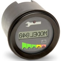
840 - Digital counter CURTIS - Free user manual and instructions
Find the device manual for free 840 CURTIS in PDF.


| Product Type | Home Appliance |
| Brand | Curtis |
| Model | 840 |
| Dimensions (L x W x H) | 30 cm x 20 cm x 15 cm |
| Weight | 2.5 kg |
| Power Supply | 120V, 60Hz, 1200W |
| Main Functions | Variable speed control, overload protection, easy-clean filter |
| Display Type | LED indicator lights |
| Noise Level | ≤ 75 dB |
| Cord Length | 1.8 m |
| Material | ABS plastic and stainless steel |
| Color | Black and silver |
| Safety Features | Thermal cut-off, grounded plug |
| Maintenance | Clean filter regularly; wipe exterior with damp cloth |
| Spare Parts | Filter, brush roll, belt (replaceable) |
| Repairability | Modular design; user-serviceable parts |
| Warranty | 1 year limited warranty |
Frequently Asked Questions - 840 CURTIS
User questions about 840 CURTIS
0 question about this device. Answer the ones you know or ask your own.
Ask a new question about this device
Download the instructions for your Digital counter in PDF format for free! Find your manual 840 - CURTIS and take your electronic device back in hand. On this page are published all the documents necessary for the use of your device. 840 by CURTIS.
USER MANUAL 840 CURTIS
CURTIS
CURTIS INSTRUMENTS, INC.
200 Kisco Ave.
Mount Kisco, New York 10549
914-666-2971 Tel
914-666-2188 Fax
www.curtisinstruments.com
53027 Rev. B 7/15
CURTIS®
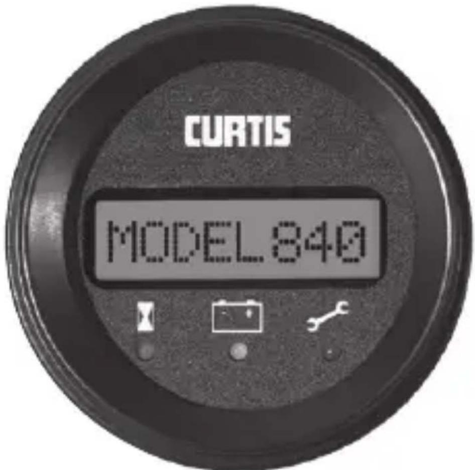
MODEL 840
Serial Data Display


Read Instructions Carefully!

SAFETY INSTRUCTIONS
This instrument was manufactured and tested according to the applicable technical standards. It complies with all the safety regulations as shipped from the factory.
Installation and startup must be performed by skilled personnel.
Failure to install and operate the unit in accordance with these instructions may result in damage or injury.
If safe operation of the instrument can no longer be ensured, stop and secure it against accidental operation.
If instrument failure or malfunction may cause personal injury or material damage, use additional safety measures such as limit switches, guards, etc.
Read the Operating Instructions carefully before startup.
Note the safety instructions marked with this warning symbol in this manual!

TABLE OF CONTENTS
- Model Encodement 2
- Technical Specifications
2.1 Electrical 4
2.2 Mechanical 4
2.3 Environmental 5
- Installation 6
- Operation 8
- Troubleshooting 9
- Maintenance 10
- Warranty 11

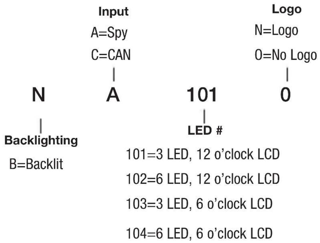
1. MODEL ENCODEMENT


2. TECHNICAL SPECIFICATIONS
2.1 Electrical Operating Voltage

Operating Current:
015R = 12.0 to 15.0 VDC
024R = 18.0 to 30.0 VDC
| 15V Models 24V Models | ||||
| Signal Name | Typical (mA) | Max. (mA) | Typical (mA) | Max. (mA) |
| B+ Heater (+24V) 133 | 180 | 133 | 180 | |
| B+ Heater (+36V) 141 | 190 | 141 | 190 | |
| PWRIN (no backlight) 26 | 39 | 26 | 39 | |
| PWRIN (w/ backlight) 43 | 66 | 43 | 66 | |
2.2 Mechanical
Display
8-character, alphanumeric, dot-matrix LCD
Molex 8-pin Mating Information:
Connector: 39-01-2085
Terminal (18–24 AWG): 39-00-0039
Terminal (16 AWG): 39-00-0078
Panel Cutouts
52mm, 2-1/16"
2.3 Environmental
Operating Temperature Range
-10°C to +70°C (Standard Model)
-40°C to +70°C (Freezer Model)
Enclosure Protection
IP65 (Face), IP40 (Rear)
Shock & Vibration
Meets SAE J 1378 (Jul 98)

3. INSTALLATION
Model 840 fits into a dash-panel cutout measuring 2-1/16" (52mm)

| Pin Number | Function | |
| "Spy" Version CAN Version | ||
| 1 No Connect CAN Hi | ||
| 2 No Connect CAN Lo | ||
| 3 B+ (Heater) 24VDC B+ (Heater) 24VDC | ||
| 4 B+ (Heater) 36VDC B+ (Heater) 36VDC | ||
| 5 B+ (Supply) B+ (Supply) | ||
| 6 Rx (Receive Data) No Connect | ||
| 7 No Connect No Connect | ||
| 8 B– B– | ||


4. OPERATION
Being a communication device, Model 840 will operate with user intervention based on signals received from a Curtis motor controller. Upon initial power-up, the instrument will go through a self-diagnostic routine in which all display elements will be illuminated for 1 second and then blanked for 1 second. The LCD will then display “all asterisks” until the first message is received. The information on the display will then be controlled by the Curtis motor controller.

5. TROUBLESHOOTING
For any deviation in operation as described in Section 4, verify model number to ensure that the voltage rating of the unit matches the power supply and check connector seating for full engagement.
6. MAINTENANCE
Model 840 is not serviceable in the field. Units returned to the factory within the warranty period (see inside backcover) without damage will be replaced without charge.

7. WARRANTY
Curtis Instruments’ products and/or components are guaranteed against defects in workmanship and material for a period of one year, or as defined in the individual product literature, from date of shipment from our factory, when applied in a proper application within specified ratings. This guarantee is limited to repair or replacement F.O.B. our factory. There is no further warranty or implied representation, guarantee, promise or agreement as to any Curtis Instruments product and/or component. Curtis Instruments, Inc., cannot assume responsibility or accept invoices for unauthorized repairs to its products and/or components, even though defective. In no case will Curtis Instruments’ responsibility extend to products, components or equipment not of its manufacture. Under no circumstances shall Curtis Instruments, Inc., be liable for any special or consequential damages or loss of profits or other damages. Returned goods will not be accepted unless identified by a Curtis Return Material Authorization (RMA).
All specifications are subject to change without notice.
- CURTIS INSTRUMENTS, INC
- CURTIS®
- MODEL 840
- SERIAL DATA DISPLAY
- SAFETY INSTRUCTIONS
- TABLE OF CONTENTS
- MODEL ENCODEMENT
- TECHNICAL SPECIFICATIONS
- 2.1 ELECTRICAL OPERATING VOLTAGE
- 2.2 MECHANICAL
- DISPLAY
- 2.3 ENVIRONMENTAL
- INSTALLATION
- OPERATION
- TROUBLESHOOTING
- MAINTENANCE
- WARRANTY
- ALL SPECIFICATIONS ARE SUBJECT TO CHANGE WITHOUT NOTICE
Brand : CURTIS
Model : 840
Category : Digital counter