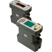
DLRO10X - Measuring equipment Megger - Free user manual and instructions
Find the device manual for free DLRO10X Megger in PDF.


| Type of product | Low Resistance Ohmmeter (DLRO) |
| Brand | Megger |
| Model | DLRO10X |
| Dimensions (H x W x D) | 220 mm x 100 mm x 40 mm |
| Weight | 0.5 kg (approx.) |
| Power supply | Rechargeable NiMH battery or mains adapter (100-240 VAC) |
| Measurement range | 0.1 µΩ to 10 Ω |
| Test current | Up to 10 A DC |
| Accuracy | ±0.2% of reading ±0.1 µΩ |
| Display | Backlit LCD, 4 1/2 digits |
| Measurement modes | Single, continuous, and triggered |
| Data logging | Internal memory for up to 1000 readings |
| Interface | USB and Bluetooth (optional) |
| Safety rating | CAT III 300V, CAT II 600V |
| IP rating | IP40 (protected against tools and small wires) |
| Operating temperature | -10°C to 50°C |
| Storage temperature | -20°C to 60°C |
| Humidity | Up to 95% non-condensing |
| Accessories included | Test leads with Kelvin clips, mains adapter, carrying case |
| Maintenance & cleaning | Wipe with damp cloth; no solvents; calibration recommended annually |
| Spare parts & repairability | Contact Megger service center for replacement leads, battery, and fuses |
| General information | Designed for low-resistance measurements in electrical and industrial applications |
Frequently Asked Questions - DLRO10X Megger
User questions about DLRO10X Megger
0 question about this device. Answer the ones you know or ask your own.
Ask a new question about this device
Download the instructions for your Measuring equipment in PDF format for free! Find your manual DLRO10X - Megger and take your electronic device back in hand. On this page are published all the documents necessary for the use of your device. DLRO10X by Megger.
USER MANUAL DLRO10X Megger
DLRO10 and DLRO10X
Digital Low Resistance Ohmmeter
User Guide
Megger
Contents
- ⚠️ SAFETY WARNINGS....4
1.1 Symbols used on the instrument 5
-
GENERAL DESCRIPTION......6
-
General Operation - DLRO10....6
3.1 Adjust the brightness control to a comfortable level. 6
3.2 Test Current Indicators 6
3.3 Noise Lamp 7
3.4 'C' and 'P' Indicators 7
3.5 'V' and 'I' Warning Indicators 7
- General Operation - DLRO10X....7
4.1 DLRO10X Top Panel 7
4.2 DLRO10X Main Menu Screen 8
4.3 Warning Messages 8
4.3.1 Noise 8
4.3.2 'C' and 'P' Indicators 8
4.3.3 External Voltage Warning 8
4.4 Discharge Current Warning 8
4.5 The Menu 8
4.6 Test Menu 9
4.7 Options Menu 9
4.7.1 Retrieve 9
4.7.2 Download 10
4.8 Passbands 10
4.9 Set Clock 11
4.10 Delete Data 11
4.11 Storage 11
4.12 Range Menu 12
4.13 Entering Notes In The Memo Screen 12
4.14 Test Result Storage 13
4.15 Keypad Operation 13
- TEST MODES 14
5.1 Normal mode 14
5.2 Automatic mode 14
5.3 Continuous mode 14
5.4 Inductive mode 14
5.5 Undirectional mode 15
- TEST TECHNIQUES and APPLICATIONS ....15
6.1 Testing Using Duplex Test Leads Fitted With Indicator Lamps 15
6.2 Testing Using Duplex Handspikes Or Individual Leads 16
6.3 Test Sequence 16
6.4 Test Lead Resistance 16
6.5 Overheating 16
7. BATTERY MODULE AND CARE....17
7.1 The Battery Module 17
7.2 Battery Charging 17
7.3 The Battery State Indicator 18
7.3.1 Standard Charging. 18
7.3.2 WARNING 18
8. SPECIFICATIONS....19
9. TROUBLE SHOOTING....21
10. ACCESSORIES....22
11. REPAIR AND WARRANTY 24
11.1 Instrument Repair and Spare Parts 24
11.2 Approved Repair Companies 24
11.3 Returning an Instrument for Repair 24
11.4 Declaration of Conformity 24
11.5 End of life disposal 24
11.5.1 WEEE 24
11.5.2 Batteries 24
1. ⚠️ SAFETY WARNINGS
These safety warnings must be read and understood before the instrument is used.
■ Whenever possible, circuits should be de-energised before testing.
- If it is impossible to de-energise the circuit, (e.g. high voltage batteries cannot be switched off while their connections are tested) the user must be aware of the dangers. The instrument terminals will become live when connected to the circuit. Therefore when used on hazardous voltages custom Megger DH6, DH6-C test leads must be used.
■ Testing inductive circuits can be hazardous:
- After testing an inductive load there will be an amount of energy stored in the inductance. This energy is released in the form of a discharge current. Disconnecting an inductive load while current is still flowing will cause a high voltage arc, which is a danger to both the user and the item under test.
Although the DLRO10 and DLRO10X are not designed as transformer ohmmeters the DLRO10 is fitted with a DISCHARGE lamp, marked 'I', which indicates that current is flowing in the C1-C2 loop. This lamp will flash at end of a test on an inductive load while a discharge current is still flowing and will stop flashing when the current has decayed to less than 1mA. DLRO10X uses a message on the display to achieve this. - For testing large inductive resistances the current carrying leads should be connected securely to the item under test before starting the test. It is not recommended that duplex handspikes be used to carry out tests on inductive loads.
- If inadvertently using the DH4 handspikes on an inductive load, the L1 lamp on the handspikes will flash amber while discharge current flows, thereby duplicating the function of the 'I' lamp on the instrument. It is important to maintain contact until the L1 light stops flashing amber and turns green indicating the end of the test.
This product is not intrinsically safe. Do not use in an explosive atmosphere.
This instrument contains a lithium-ion high energy battery pack.
- Do not pierce, damage, disassemble or modify the battery.
- The battery contains safety and protection devices, which if tampered with may cause the battery to generate heat, rupture or ignite.
- If a battery module is suspected to contain a faulty battery cells - do not ship the faulty battery module, either separately or inside an instrument.
-
The instrument must be set to OFF and the lid must be installed and securely closed before the instrument is shipped.
-
Do not heat or dispose of the battery in a fire.
- Do not subject the battery to strong impact, mechanical shock or excessive heat.
- Do not short-circuit or reverse the polarity of the battery pack.
Please note. The neck strap is specifically designed to break if subjected to a strain of approximately 50 kg.
CAT II - Measurement category II: Equipment connected between the electrical outlets and the user's equipment.
CAT III - Measurement category III: Equipment connected between the distribution panel and the electrical outlets.
CAT IV - Measurement category IV: Equipment connected between the origin of the low-voltage mains supply and the distribution panel.
1.1 Symbols used on the instrument
 | Caution: Refer to accompanying notes |
 | Equipment protected throughout by Double or reinforced Insulation (Class II) |
 | Equipment complies with current UKCA legislation |
 | Equipment complies with current EU Directives |
 | Equipment complies with current 'C tick' requirements |
 | Do not dispose of by landfill, sewage systems or by fire |
2. GENERAL DESCRIPTION
The DUCTER DLRO10 and DUCTER DLRO10X make up a family of low resistance ohmmeters that measure resistances in the range from 0.1 μΩ to 2 kΩ. Both instruments provide a maximum test current of 10 Amps d.c. which is automatically selected according to the value of resistance being tested. The DLRO10X allows you to override this automatic selection and select your own test current.
The measured value of resistance is output to the instrument display with indication of the units, µΩ , m Ω or Ω . The DLRO10 uses a large LED display and indicators to display the value and units respectively, while the DLRO10X contains all the information on a clear colour display.
The use of a four terminal measurement technique removes the test lead resistance from the measured value and auto current reversal eliminates the effect of standing voltages across the test sample. Additionally, before and during a test, test lead contact is monitored to further reduce the chance of erroneous readings.
A resistance measurement takes approximately 2.5 seconds and comprises a measurement with forward current, reverse current and a display of the average. On the DLRO10X all three values are displayed, and optionally, the measurement may be limited to forward current only.
The instrument is powered by a rechargeable Lithium ion (Li-ion) battery, which permits thirteen hundred 10 Amp tests to be completed on a single charge. The battery module contains intelligent circuitry, which prevents damage to the battery from overcharging, and a battery state indicator. A removable lid that is hinged at the back and held closed by magnetic catches covers the top panel. This lid may be removed if required by opening fully and snapping out of its hinges.
Both instruments are protected against accidental connection to external voltages up to 600 V d.c. applied between any pair of the four terminals for up to 10 seconds.
Please note that applying 600 V to the potential terminals will cause some internal heating. Expect errors of up to 30 digits immediately after the application of such voltage. Full accuracy will be restored within two to three minutes.
Both instruments are supplied complete with a pair of DH4 Duplex Handspikes with 1.2 m leads. Other lengths and terminations are available if required.
3. General Operation - DLRO10

| Item Description Item Description | ||
| 1 Test current 5 Excess noise | ||
| 2 Contact fail indicator 6 Mode control | ||
| 3 Voltage terminals 7 Brightness | ||
| 4 Current flowing 8 On/Off |
Press the On/Off switch to turn DLRO10 on. All lamps will light, V and I lamps will flash, the software version will be displayed and the Ω lamp will light. If the test leads have not been connected to the test sample the 'C' and 'P' lamps will also light. Press the On/Off button again to turn the instrument off. If the instrument is not used for 5 minutes it will be turned off automatically.
3.1 Adjust the brightness control to a comfortable level.
Select the Test mode by pressing the Mode button repeatedly. The indicator lamps will cycle through the various Test modes in turn (see the section on Test modes). Press the Test button to start a test.
3.2 Test Current Indicators
The test current is selected automatically by DLRO10 and is indicated by the lamps on the left of the panel. The measured value is displayed in the main window and the units ( µΩ , m Ω or Ω ) are shown by the lamps to the right of the window.
3.3 Noise Lamp
Noise in excess of 100 mV 50/60 Hz will light the 'Noise' lamp and measurement accuracy cannot be relied upon.
3.4 'C' and 'P' Indicators
The 'C' lamp illuminates to indicate contact failure in the 'C1-C2' loop. The 'P' lamp illuminates when there is a break in the P1-P2 loop.
3.5 'V' and 'I' Warning Indicators
If external voltage is applied to the terminals the 'V' lamp will flash. This is a warning that the item under test is live and might be dangerous. A test cannot be performed in this condition.
The 'V' lamp will light if more than 50 V, is applied between either voltage terminal and a current terminal. If the voltage appears between just the voltage terminals or just the current terminals the lamp will light at 100 V peak or 5 V peak respectively.
Please note - The 'V' lamp will only indicate if a voltage appears between terminals. The lamp will not operate if all terminals are at the same high voltage. The lamp will not operate if the instrument is turned off.
The 'I' lamp will light if a current greater than 1 mA is still flowing after a test is completed. This suggests that an inductive load has been tested and is still discharging. Do not disconnect the current loop until the 'I' lamp has gone out.
4. General Operation - DLRO10X
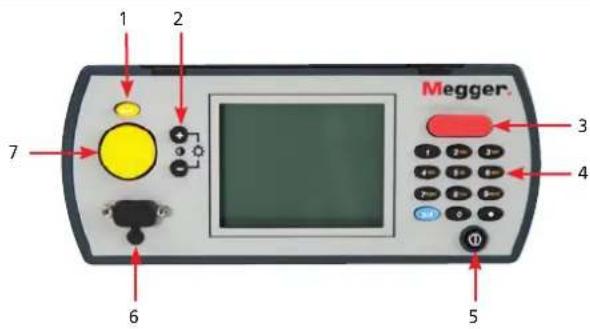
| Item Description Item Description | ||
| 1 Back key 5 On/Off | ||
| 2 Back light control 6 RS232 port | ||
| 3 Test button 7 Cursor control | ||
| 4 Key pad |
4.1 DLRO10X Top Panel
All the controls needed to set up and operate DLRO10X are located on the top panel of the instrument.
To the left of the large colour display are the controls for moving around the display, controlling the menu and adjusting the display contrast and backlight.
To the right of the display is the large Test button, Power On/Off button and an alphanumeric keypad for entering notes relating to a test which will be stored with the test results for later reference.
To turn your DLRO10X on, press the On/Off button for approximately 1 second. Press again to turn the instrument off. If the instrument is not used for 5 minutes it will be turned off automatically.
4.2 DLRO10X Main Menu Screen
When first switched on DLRO10X displays a copyright screen, followed by the Main Menu screen.

This screen provides you with information such as battery charge remaining, index number of the next test, number of tests already stored and the current date and time.
This screen also provides access to the menu, through which you set up your instrument and choose the desired test parameters. Navigation of this menu is by means of the cursor control and Enter key.
4.3 Warning Messages
The Main Menu screen will from time to time also contain certain warning messages
4.3.1 Noise
Noise in excess of 100 mV 50/60 Hz will activate the message 'Noise' at the bottom of the display. Above this level accuracy cannot be relied upon.
4.3.2 'C' and 'P' Indicators
A good measurement requires both the current carrying circuit and the voltage detection circuit to be completed by the item under test. DLRO10X checks for this continuity. If there is poor continuity in either circuit a message will appear at the bottom of the display. This will read "P OPEN CIRCUIT" if the voltage contacts are high resistance, "C OPEN CIRCUIT" if the current circuit is not made or "CP OPEN CIRCUIT" if both circuits are inadequate. Check the contacts, since a measurement cannot be made if any of these messages is visible on the display.
4.3.3 External Voltage Warning
If external voltage is applied to the terminals a message "EXT VOLTS" will flash on the display. This is a warning that the item under test is live and might be dangerous. A test cannot be performed in this condition.
The "EXT VOLTS" message will flash if more than 50 V. is applied between either voltage terminal and a current terminal. If the voltage appears between just the voltage terminals or just the current terminals the message will appear at 100 V peak or 5 V peak respectively.
Please note - The message will only appear if a voltage appears BETWEEN terminals. The message will not appear if all terminals are at the same high voltage. The message will not operate if the instrument is turned off.
4.4 Discharge Current Warning

A message CURRENT FLOW will appear if a current greater than 1 mA is still flowing after a test is completed. This suggests that an inductive load has been tested and is still discharging. Do not disconnect the current loop while the discharge warning is showing.
4.5 The Menu
Use the Left and Right arrows of the cursor control to highlight the menu required. Press the Down cursor control to see the options available on that menu. Select the required option using the cursor control and press Enter to set that option. Depending on the menu item selected the display will either present further options or will return to the main menu screen.
4.6 Test Menu

This sub-menu selects the test mode. Only one mode can be active at a time and the active mode is displayed below the heading TEST. (See Test Modes later in this manual for details of each mode.)
There is a quick access menu that can be accessed using the numbers keys as follows:-
| 0 Normal |
| 1 Automatic |
| 2 Inductive |
| 3 Continuous |
| 4 Unidirectional |
Although designed to assist quick selection of the test modes, please be aware that pressing these keys can inadvertently change the test mode.
4.7 Options Menu
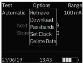
The Options menu has five options that are not related to each other, as shown below.
There is a quick access menu that can be accessed using the numbers keys as follows:-
| 0 Retrieve |
| 1 Download |
| 2 Passbands |
| 3 Set Clock |
Although designed to assist quick selection of the options, please be aware that pressing these keys can inadvertently change the option. The Delete Data option has been disabled from the quick access navigation.
4.7.1 Retrieve
Allows the recall of stored results to the display or a PC.
Recalls each test, in sequence, to the instrument display starting with the latest stored result.
Use the cursor control Up and Down controls to step later or earlier respectively through the stored results.


At the bottom of the test screen a memo will display for one associated with the test otherwise the test will display "memorandum goes here..." which means that there are no notes attached to this result.
Press the right cursor control to view any available notes.
4.7.2 Download
Causes the entire contents of the data store to be output to the RS232 port to the left of the display. A copy of AVO Download Manager, which facilitates downloading and formats the data, is supplied.
Downloading data does not cause the stored data to be erased from memory. To clear data from memory see "Delete Data" below.
Please note - DLRO10X also makes data available via the RS232 Port in real time and is suitable for printing on a self-powered serial printer.
The output has the following form:
TEST NUMBER
TEST TYPE
DD MM YY HH MM
01/01/00 00:33
FORWARD RESISTANCE
REVERSE RESISTANCE
AVERAGE RESISTANCE
SELECTED CURRENT
UPPER LIMIT
LOWER LIMIT *
PASS/FAIL *
*The last three lines will only appear if passbands have been set
4.8 Passbands
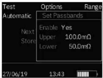
This option allows you to set upper and lower limits between which the test result average must fall if it is to be signalled as a Pass (GREEN). Readings outside these limits will be signalled as a Fail (RED).
Set the passbands to ENABLE to yes to allow the upper and lower passbands to be set.
Values are entered via the keypad complete with decimal points, where applicable, and including µ or m (See section on the Alphanumeric Keypad). Repeatedly pressing the blue 9/A button cycles between ohms, milliohms, microohms. It is not necessary to enter the Ω symbol. The upper limit must be less than or equal to 2000.0 Ω and the lower limit must be less than the upper limit.
During entry of the upper limit DLRO10X will check validity of the entered values and beep to advise if above accepted limits. After completing the upper limit use the right cursor key to move to the lower limit. Enter the lower limit then press Enter.
You will now return to the Main Menu screen.
Note: Passbands will remain enabled or disabled until you enter this screen and change the selection. If all that is required is to change Passbands from ENABLED to DISABLE or vice versa, enter the PASSBAND screen and press Enter until the ENABLED / DISABLED choice is shown at which time you may change the selection.
4.9 Set Clock
This option sets the real time clock date and time settings as well as setting the date format. When you enter this screen the current date, time and date format will be displayed.
Use the cursor control Up and Down arrows to adjust the highlighted data. Step to the previous/next item by using the Left/Right cursor control arrow.
The date is only available as a four digit year. The time is only available in 24h notation.
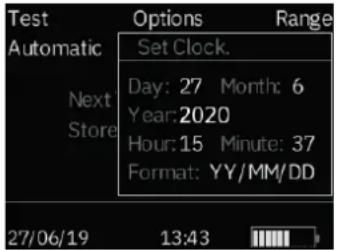
The lower YY/MM/DD shows the current date format. Pressing the cursor control Up arrow will cycle through the available options DD/MM/YY, MM/DD/YY or YY/MM/DD. The bottom line shows the current setting of date and time. This is updated when you press Enter to exit the Set Clock function. Tests already stored prior to changing the date format will change to the new format.
4.10 Delete Data
Select Delete Data if you wish to clear DLRO10X's memory of stored data. In case you have selected this Option by accident you will be asked to confirm that you wish to delete the data; the default is NO. Change this to YES and press Enter if you wish to delete all data.
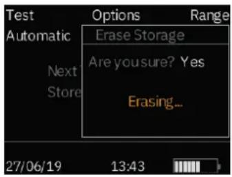
Please note - ALL stored data will be deleted.
4.11 Storage
The Storage option sets the default for data storage. It may be set to always store data or never to store data. Highlight the desired option at the bottom of the screen and press Enter.
With the exception of tests carried out in Continuous mode, at the end of each test you have the option to change the default by selecting STORE or NO STORE at the bottom of the results screen.
At the end of a test, if memory is full this STORE / NO STORE message will change to MEMORY FULL and no more tests will be stored.
Data is stored indefinitely if a charged battery pack is fitted. If the main battery becomes exhausted or is removed, data is maintained for a period of 4 days by an internal backup battery. When a charged battery pack is refitted, the backup battery will recharge to full capacity within 1 week.
4.12 Range Menu
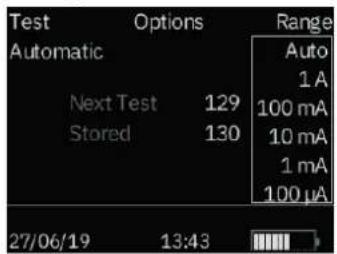
DLRO10X uses a test current between 100 µ A and 10 A to measure the resistance of the item under test. If set to AUTO, DLRO10X will select the current according to the resistance it detects. (see Specifications, Ranges)
However, in some cases it may be desirable to set a maximum test current (subject to a maximum 10 A.) If this is so, move the cursor to the desired current and press Enter. Six test currents are available; 10 A, 1 A, 100 mA, 10 mA, 1 mA and 100 μA.
Selecting the 10 A maximum will have the same effect as selecting AUTO.
On the DLRO10X please note - it needs to be understood that the "Range" is actually the selected maximum test current.
The ability to set the maximum test current is only applicable to non-inductive test modes. The inductive test is automatically limited to 1A.
When Battery level is low (<10%), the maximum test current is automatically reduced (by one level) and will be further reduced when a test has to be abandoned because the battery cannot supply this initial reduced test current.
The Main Menu screen will show the active current range beneath the RANGE heading.
There is a quick access menu that can be accessed using the numbers keys to set the maximum test current as follows:-
| 0 Auto 10 A | |
| 1 1 A | |
| 2 100 mA | |
| 3 10 mA | |
| 4 1 mA | |
| 5 1 μA | |
Although designed to assist quick selection of the maximum test current, please be aware that pressing these keys can inadvertently change the current.
4.13 Entering Notes In The Memo Screen

At the end of each test, (with the exception of a test in Continuous mode). You can change the option to store the test results or not buy changing the option STORE to YES or NO. Select the desired option using the cursor control (UP/DOWN). This overrides the default setting under Options, Storage for one test only.

If you wish to add comments to the test results, instead of pressing Enter, briefly press one of the twelve keys on the keypad. You will enter a memo screen that allows you to enter up to 200 characters of alphanumeric information concerning the test. When you have entered all information press Enter and the measurement and memo will be stored regardless of whether STORE YES or NO was selected.
If you do not wish to add notes and are happy to accept the default STORE YES or NO setting you may press the Test button and a new test will be started.
4.14 Test Result Storage
Each test is numbered, starting at test 1. This test number is incremented automatically, as each result is stored. The test result memory can store a maximum of 700 tests, each being identified by its test number, date and time.
It is advisable to retrieve all data to a PC and then to delete all data before the test number reaches this maximum. This will save loss of data.
Deleting the data will reset the test number to 1.
4.15 Keypad Operation
The 12 key keypad is similar to those used on mobile telephones in that each key is capable of producing one of several characters depending on the number of times the key is pressed.
The keypad is used to enter data into the Memo field.

Pressing the blue key marked 9/A changes the function of the keyboard between upper/lower alpha and numeric modes.
In alpha mode
The keys 2 to 9 will produce the letter shown on the keys depending on the number of presses. For example if the 2 key is pressed once an 'A' will appear, twice and a 'B' will appear etc. Pausing will cause the cursor to move on to the next character.
The 0 key produces a space.
The 1 key is a backspace delete.
The key at the bottom right hand corner of the keypad marked with a dot is a special key that produces 9 special symbols. Each quick press will sequentially produce the character shown:
| . Decimal point or full stop |
| - Hyphen, dash or minus sign |
| μ Symbol for micro |
| Ω Ohms symbol |
| , comma |
| ; semi colon |
| : Colon |
| # Symbol known as hash or pound and commonly used as shorthand for "number" |
In numeric mode
The keys marked 1 - 9 and 0 produce that number when pressed. Press the respective key briefly to enter the desired number.
5. TEST MODES
DLRO10 has 4 test modes which are selected by repeated presses of the Mode button. At the end of each test, DLRO10 will display the average of the values obtained with forward and reverse current.
DLRO10X has 5 modes. On DLRO10X these modes are selected from the TEST menu using the cursor control and Enter key. At the end of a test, DLRO10X will show three resistance values; that obtained with forward current, that obtained with reverse current and the average value.
5.1 Normal mode
Normal mode makes a single measurement of the resistance of the sample using forward and reverse current
Please note that in this mode both the current and voltage leads must be connected across the test sample before the Test button is pressed. To make another measurement, ensure the test leads are connected and press the test button.
5.2 Automatic mode
If Automatic mode is selected, your instrument will remain in a state of readiness waiting for both the current and voltage measuring leads to be connected to the test piece. When this is done, a forward and reverse current test will be started automatically.
To make another measurement simply break contact with the test sample and remake contact.
For example, if measuring joints in a long bus bar, you may leave the current circuit connected at opposite ends of the bus bar. Simply making contact with voltage probes across the joint(s) you wish to measure will then activate the measurement.
5.3 Continuous mode
Continuous mode requires the connections to be made before pressing the Test button. Your instrument will then repeat its forward and reverse measurements and display the results approximately every 3 seconds until contact is broken or the Test button is pressed.
5.4 Inductive mode
DLRO10 and DLRO10X are able to make d.c. resistive measurements on loads that exhibit an inductive component using the test mode indicated by the inductor symbol on the DLRO10, or by using the inductive mode on the DLRO10X.
When measuring inductive loads it is essential that the current carrying leads are securely clamped to the item being tested and that they are not removed before any stored charge has been discharged at the end of the test. Failure to comply with these instructions might result in an arc being produced, which might be dangerous for the instrument and the operator.
Having selected inductive mode, connect all four leads to the item being tested and press the Test button.
DLRO will check that all four leads are in adequate contact with the test piece and will then apply a test current and try to find the correct range. The display will show 1 -- followed by 1 ----. During this time you may see the current range increasing or decreasing.
On the DLRO10 the "I" lamp will flash and the message "Current Flowing" will appear.
On the DLRO10X display "Precharge" will appear briefly followed by arrows moving left to right, the test current will auto-range up and then "Measuring" will be displayed on the screen. Once readings have stabilised, the operator can then press the test button to stop the test. The instrument will then auto-range down and show "Discharging" as the energy stored in the inductive load is discharged and finally "Complete" will be displayed, at this point it should be safe to disconnect the "C" Leads.
The time required for a stable reading may vary from a few seconds up to several minutes depending on the inductance and resistance of the test sample. There is no time limit for the inductive mode test, which will continue until the operator presses the Test button.
When the test is terminated, the "I" lamp will remain illuminated on the DLRO10. When these messages are extinguished it should be safe to disconnect the "C" leads. However, the discharge indicator is an active electronic device and should not be relied upon. You should observe your organisation's operating procedures.
At the end of the test both instruments will display the measured resistance, the DLRO10 will flash the relevant current lamp while the DLRO10X will display the test current used on the display.
Please note:- In inductive mode the 10 A test current will not be used.
5.5 Undirectional mode
On the DLRO10X only, this mode makes the measurement as in automatic mode but using forward current only.
This mode speeds up measurements on samples that are known to be free of any standing voltages or thermal emfs. However the accuracy of the reading may be degraded by any thermal emfs but should not be worse than 0.2% ± 30 digits.
Since current is only applied in the forward direction, in this mode only a single resistance value will be displayed.
A test may be repeated by breaking contact and reapplying the test probes or by pressing the Test button.
6. TEST TECHNIQUES and APPLICATIONS
6.1 Testing Using Duplex Test Leads Fitted With Indicator Lamps
Each handspike is marked with the letter P. This indicates the potential terminals. These should be the 'inside' contacts when making a measurement (as shown in the next section 'Testing Using Duplex Handspikes or Individual Leads').
One of the DH4 handspikes is fitted with two lamps marked L1 and L2 and an extra lead. This lead should be plugged into the 4 mm socket next to the main terminals on the right hand side of the instrument. These lamps provide information to the operator, which would otherwise only be available on the instrument display. The meaning of these lamps is described below.
For example, using the DH4 or DH4-C Duplex Handspikes or any connecting test leads with indicator lights with the DLRO10 in AUTO test mode:
- Press the TEST button on the instrument.
- Lamp L1 will illuminate a continuous red to indicate contact failure. See the instrument panel for details if required.
- When all four contacts connect, L1 will extinguish.
- No lamps will show during the test unless contact fails.
- Lamp L2 will light a continuous green when current flow has decayed to less than 1 mA to signal end of test.
- Removing the probes will extinguish the green L2 (end of test) and Light the red L1 (no contact).
Since your DLRO always ensures good contact before applying the full test current, there will be no 'splash' to erode the contact tips. However, should the tips become worn or blunted, they can be simply replaced by pulling out the worn tips and inserting new ones.
DLRO 10 and DLRO 10X (no passbands)
| Lamp L1 Lamp L2 Meaning | |
| Red Off Inadequate contact at C and/or P contacts | |
| Flashes Red Off Voltage present between contacts (DLRO10 Only) | |
| Off Green Current less than 1 mA and test complete. | |
| DLRO10X ONLY if pass bands set | |
| Lamp L1 Lamp L2 Meaning | |
| Off Green Measurement Pass | |
| Off Red Measurement Fail |
6.2 Testing Using Duplex Handspikes Or Individual Leads
Connect the four leads as shown.
![graph TD A["C"] --> B["Line"] C["P"] --> B D["P"] --> B E["C"] --> B](/content/2026/07/1423915/images/51ac2e2ae3b77d76a09518efe14b830ff3b874cb4d3b7344b9f884bac1a5fbeb.jpg)
If using Duplex Handspikes ensure that the probe marked P is inside the C probes.
Note: When used on hazardous voltages Megger DH6 test leads must be used.
6.3 Test Sequence
Pressing the TEST button starts the test sequence.
Contact resistance is checked by passing 100 µ A through the C1-C2 loop and checking that the voltage is less than 4 V. Then passing 80 µ A through the P1-P2 loop and checking that the voltage is less than 250 mV. If either value is exceeded the respective lamp or warning message will be displayed.
When all faults have been rectified the test current is increased until the voltage on P1-P2 is within the 2 mV to 20 mV range. This current is then applied in a forward and then reverse direction to obtain two measurements.
Both measurements are displayed by DLRO 10X along with the average, while the DLRO 10 displays the average only.
If the combined resistance of the current leads and test sample is greater than 100 mΩ, testing at 10 A will not be possible.
A 1.9 mΩ resistor will then be tested at the next lowest current (1 A) and the result will be shown as 1.900 mΩ instead of 1.9000 mΩ.
6.4 Test Lead Resistance
For testing at 10 A, the combined resistance of the current leads must not exceed 100 mΩ. This will ensure that the voltage drop in the leads is less than 1 volt and will enable 10 A testing under worst case conditions. If you wish to limit test current to no more than 1 A, on DLRO 10 use current leads with a resistance of about 1 Ω, or on DLRO 10X select 1A as the maximum test current on the RANGE submenu.
6.5 Overheating
When performing rapidly repeated tests at 10 A, using current leads with a combined resistance of 100 mΩ, 10 W of heat will be dissipated in the leads and 30 W within your instrument. If the ambient temperature is high this will cause internal overheating and the message "hot" will appear on the instrument display and testing will be halted.
After a few minutes to cool down, testing will be allowed to continue.
If this is a persistent problem, use current leads with a higher resistance (e.g. 200 mΩ to 300 mΩ). This will reduce the generation of internal heat.
7. BATTERY MODULE AND CARE
7.1 The Battery Module
The battery module contains lithium cells and has a built-in battery-management system that controls charging and monitors discharge. This provides a high capacity, low-weight battery system, which can be recharged at any time. It is not possible for the user to over-charge or over discharge the battery. For your own convenience it is best to charge it regularly to keep it topped up, but leaving it in a discharged state will do no harm.
The front of the battery module has one button and a 10-segment LED display.
Battery Condition Battery State Indicator
To find the amount of charge in your battery module, whether connected to your DLRO or separate, press the Battery Condition Button. The Battery State indicator will light between 1 and 10 segments signifying between 10% and 100% charge respectively. After a few seconds this display will automatically go out. A single flashing LED indicates less than 10% charge and 'BATT' is displayed.
DLRO10: When the display shows 'BATT=', the battery has less than 20% charge. Pressing the test button removes the warning and allows use of the instrument with lower output current.
7.2 Battery Charging
Please note - The battery should only be charged within the temperature range 0 °C to 40 °C.
To charge the battery, your battery module must be removed from the instrument. Remove the module by pressing on the raised circular area of the retaining clips and pull the top of the clip away from the instrument body. The module now unplugs from the base of the instrument.
Plug in the charger or connect to a 12 volt vehicle-type battery using the 'cigar lighter' lead provided. The LED "Battery State" indicator will light and show movement when the battery is charging. The battery may be recharged before it has been fully discharged. It will normally be recharged to 90% of capacity within 2.5 hours. Full charge may take up to 4 hours before indicating that the battery is full depending on the initial state of the battery. When charging is complete the battery management circuitry will switch off so that over-charging is prevented.
Your battery module can be safely used in a partially charged state and will not suffer if stored in a discharged state. However, you may wish to have a spare battery that can be interchanged with the one in use to provide continuous use of your DLRO.
A fully charged battery, even if not used, will self discharge over a period of several months (faster at higher temperatures). Always check the "Battery State" indicator before starting work. A fully charged battery will light all segments. A fully discharged battery will light no segments.
Please note that all batteries suffer a reduced life if exposed to constant high temperatures. A constant temperature of 30\ °C will probably cause the battery to fail in less than 5 years. 40\ °C will shorten its life to 2 years.
7.3 The Battery State Indicator
The Battery State Indicator provides information on the amount of charge in the battery, but is also used to signal other conditions as follows:
7.3.1 Standard Charging.
The battery module is charging at its standard rate.
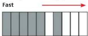
Battery state flashing during charging indicates temperature fault.
7.3.2 WARNING
Connecting to greater than 15 volts can cause permanent damage to the battery module.
The DLRO10 and DLRO10X can also be powered from a mains / line power supply unit the DLRO10LPU. This is available as an accessory, details can be found in the Accessories section of this user guide

8. SPECIFICATIONS
Ranges
| Full Scale Resolution Accuracy Full Scale Volts Test Current | ||||||
| Resistance Induction Resistance Induction | ||||||
| 1,9999 mΩ 0,1 μΩ ±0,2%, ±0,2 μΩ 20 mV 10 A 1 A | ||||||
| 19,999 mΩ | 1 μΩ | ±0,2%, ±2 μΩ | 20 mV | 20 mV | 1 A | 1 A |
| 199,99 mΩ | 10 μΩ | ±0,2%, ±20 μΩ | 20 mV | 200 mV | 100 mA | 100 mA |
| 1,9999 Ω | 100 μΩ | ±0,2%, ±0,2 mΩ | 20 mV | 200 mV | 10 mA | 10 mA |
| 19,999 Ω | 1 mΩ | ±0,2%, ±2 mΩ | 20 mV | 200 mV | 1 mA | 1 mA |
| 199,99 Ω | 10 mΩ | ±0,2%, ±20 mΩ | 20 mV | 200 mV | 100 μA | 100 μA |
| 1999,9 Ω | 100 mΩ | ±0.2%, ±0.2 Ω | 200 mV | 200 mV | 100 μA | |
| DLRO 10 | DLRO 10X | ||
| Display | Measurement | 4 1/2 digit seven segment LED | Large colour backlit |
| Range and Safety | LED Indication | ||
| Measurement | Mode | Manual, Auto, Continuous, Inductive | Manual, Auto, Continuous, Inductive, Unidirectional. |
| Control | Fully Automatic | Fully Automatic with manual override of maximum current | |
| Speed <3s for forward and reverse current and to display average | |||
| Test Method | Single cycle reversing DC ratiometric measurements and average result calculated. | ||
| Test Current Accuracy | 10% | ||
| Output Current Stability | <10 ppm per second @ 10 mA<100 ppm per second at higher currents | ||
| Maximum Lead Resistance | 100 mΩ total for 10A operation irrespective of battery condition. | ||
| Voltmeter Input Impedance | >200 kΩ | ||
| Hum Rejection | Less than 1% ± 20 digits additional error with 100 mV peak 50/60 Hz. on the potential leads. Warning will show if hum or noise exceeds this level. | ||
| Data Transfer Real Time or from storage via RS232 | |||
| Storage 700 tests | |||
| Memo Field Up to 200 characters per test via integral | alphanumeric keypad. | ||
| Battery Capacity 5.2 Ah Li ion | |||
| Life Typically 1300 x 10 A tests before recharge | |||
| Recharge 12 to 15 V DC supply | |||
| Charging Time 4 hrs for full charge | |||
| Temperature Operation | +5 °C to +45 °C (41 °F to 113 °F) at full specification.-10 °C to +50 °C (14 °F to 122 °F) at reduced accuracy | ||
| Storage -30 °C to +70 °C (-22 °F to 158 °F) | |||
| Calibration 20 °C (68 °F) | |||
| Coefficient | <0.01% per °C from 5 °C to 40 °C (<0.006% per °F from 41 °F to 104 °F) | ||
| Standard charging | 0 °C to +40 °C (32 °F to 104 °F) | ||
| Humidity | Max | 90% RH @ 40 °C (104 °F) non-condensing | |
| Altitude Max | 2000 m (6562 ft.) to full safety specifications | ||
| Safety | In accordance with IEC61010-1 600 V Category III - only when DH6 leads are used | ||
| EMC | In accordance with IEC61326-1 | ||
| Dimensions (HxWxD) | With Battery 245 x 237 x 100 mm (9.6 x 9.3 x 4 inch) | ||
| Without Battery 171 x 237 x 100 mm (6.7 x 9.3 x 4 inch) | |||
| Weight | With Battery 2.46 kg (5.42 lb) | ||
| Without Battery 1.48 kg (3.26 lb) | |||
9. TROUBLE SHOOTING
| Error Message Fault Action required. | ||
| bAtt The main battery module is low. Recharge the main battery or replace with a charged one | ||
| ____ An error has occurred during the measurement.e.g. contact has been lost at one of the probes | Rectify the error and repeat the measurement. | |
| ERR 114 Checksum Failure in EEPROM. Calibration constants have been lost.The DLRO will continue to work but the accuracy can now not be guaranteed. At switch on the display will show the software version with dashes each side e.g. - 1.0 - | Return for recalibration. | |
| ERR 115 Checksum Failure in battery backed RAM. This can occur if the main battery module and the backup battery become completely exhausted. | Recharge the main battery or replace it with a charged one. Switch the instrument on. Calibration constants will be retrieved from EEPROM. | |
10. ACCESSORIES
Standard Accessories supplied with all instrument.
| Battery DLRO10/10X 5.2 Ah 6121-492 |
| User guide DLRO10/10X 6172-681 |
| Warranty / Cert of Test [1 YEAR] MEGGER 2000-231 |
Test leads supplied with instruments
| DLRO10-NLS Ducter Ohmmeter NO LEAD SET 1006-660 |
| DLRO10X-NLS Ducter Ohmmeter NO LEAD SET 1006-659 |
Optional Accessories at extra cost
| Carrying Case for DLRO10/10X + all accessories 6380-138 |
| Calibration Shunt, 10 Ω, current rating 1 mA 249000 |
| Calibration Shunt resistor, 1 Ω, current rating 10 mA 249001 |
| Calibration Shunt resistor, 100 mΩ, current rating 1A 249002 |
| Calibration Shunt resistor, 10 mΩ, current rating 10 A 249003 |
| Calibration certificate CERT-NIST |
DLRO10LPU line power unit

The DLRO10 and DLRO10X may be also powered from an optional mains / line power supply unit the DLRO10LPU. This unit is simply fitted to the instrument in place of the standard battery pack.
When in use a red LED is illuminated when the instrument is powered from a mains / line power supply. The DLRO10X is seen here fitted with the optional DLRO10LPU. Ideal for repetitive testing applications such as manufacturing production line use
Optional Test Leads at extra cost Duplex Leads Normal test leads not fitted with inline connector:
| DH4-C Connect Duplex Handspike 1.5m (x2) | 1006-444 | |
| DH5 straight duplex handspikes (2). One has indicator lights. | ||
| 2.5 m/8 ft | 6111-517 | |
| DH6 Duplex handspikes (2) suitable for working on 600 V. systems. | ||
| 2.5 m/8 ft | 6111-518 | |
| Duplex Handspikes (2)with spring loaded helical contacts. | ||
| 2 m/7 ft | 242011-7 | |
| 2.5 m/8 ft | 6111-022 | |
| 5.5 m/18 ft | 242011-18 | |
| 6 m/20 ft | 6111-023 | |
| 9 m/30 ft | 6111-024 | |
| Straight Duplex Handspikes (2) Heavy Duty with fixed contacts. | ||
| 2 m/7 ft | 242002-7 | |
| 5.5 m/18 ft | 242002-18 | |
| 9 m/30 ft | 242002-30 | |
| Duplex Heavy Duty 5cm (2") C-Clamps. (2) | ||
| 2 m/7 ft 242004-7 | ||
| 5.5 m/18 ft 242004-18 | ||
| 9 m/30 ft 242004-30 | ||
| Duplex handspikes with replaceable Needle Points | ||
| 2 m/7 ft 242003-7 | ||
| Duplex 1.27 cm (1/2") Kelvin Clips. (2) | ||
| gold plated 2 m/7 ft | 241005-7 | |
| silver plated 2 m/7 ft | 242005-7 | |
| Duplex 3.8 cm (11/2") Kelvin Clips. (2) | ||
| 2 m/7 ft 242006-7 | ||
| 5.5 m/18 ft 242006-18 | ||
| 9 m/30 ft 242006-30 | ||
| Single Leads | ||
| Single handspikes (2) for potential measurement. | ||
| 2 m/7 ft 242021-7 | ||
| 5.5 m/18 ft 242021-18 | ||
| 9 m/30 ft 242021-30 | ||
| Current clips (2) for current connections. | ||
| 2 m/7 ft 242041-7 | ||
| 5.5 m/18 ft 242041-18 | ||
| 9 m/30 ft 242041-30 | ||
Test leads fitted with inline connector:
Add the part numbers of the complete lead sets and refer customers to the test lead data sheet for the individual parts
For detailed information on connecting lead accessories refer to the DLRO test leads User Guide available on www.megger.com or via the QR code below:

11. REPAIR AND WARRANTY
The instrument circuit contains static sensitive devices, and care must be taken in handling the printed circuit board. If the protection of an instrument has been impaired it should not be used, and be sent for repair by suitably trained and qualified personnel. The protection is likely to be impaired if, for example, the instrument shows visible damage, fails to perform the intended measurements, has been subjected to prolonged storage under unfavourable conditions, or has been exposed to severe transport stresses.
New Instruments are Guaranteed for 1 Year from the Date of Purchase by the User.
Note: Any unauthorised prior repair or adjustment will automatically invalidate the Warranty.
11.1 Instrument Repair and Spare Parts
For service requirements for Megger Instruments contact:-
| Megger Limited | Megger Valley Forge |
| Archcliffe Road | 400 Phoenixville |
| Dover | PA 19460 |
| Kent, CT17 9EN. | U.S.A. |
| England. | Tel: +1 (610) 676-8500 |
| Tel: +44 (0) 1304 502100 | Fax: +1 (610) 676-8610 |
| Fax: +44 (0) 1304 207342 |
or an approved repair company.
11.2 Approved Repair Companies
A number of independent instrument repair companies have been approved for repair work on most Megger instruments, using genuine Megger spare parts. Consult the Appointed Distributor / Agent regarding spare parts, repair facilities and advice on the best course of action to take.
11.3 Returning an Instrument for Repair
If returning an instrument to the manufacturer for repair, it should be sent freight prepaid to the appropriate address. A copy of the Invoice and of the packing note should be sent simultaneously by airmail to expedite clearance through Customs. A repair estimate showing freight return and other charges will be submitted to the sender, if required, before work on the instrument commences.
NOTE: The batteries are Li-ion and disposal of cells should be in accordance with local regulations.
11.4 Declaration of Conformity
Hereby, Megger Instruments Limited declares that radio equipment manufactured by Megger Instruments Limited described in this user guide is in compliance with Directive 2014/53/EU.
Other equipment manufactured by Megger Instruments Limited described in this user guide is in compliance with Directives 2014/30/EU and 2014/35/EU where they apply. The full text of Megger Instruments EU declarations of conformity are available at the following internet address: megger.com/eu-dofc.
11.5 End of life disposal
11.5.1 WEEE
The crossed out wheeled bin placed on the Megger products is a reminder not to dispose of the product at the end of it's product life with general waste.
Megger is registered in the UK as a Producer of Electrical and Electronic Equipment. The Registration No is WEE/HE0146QT
11.5.2 Batteries
The crossed out wheeled bin placed on the batteries is a reminder not to dispose of them with general waste at the end of their life.
This product contains Li-ion batteries.
Battery replacement should only be performed by a Megger authorised repair agent, who will correctly dispose of the spent battery.
For the purpose of end of life disposal only, a lithium battery pack is located in the battery module and a lithium coin cell is located behind the display. Dispose of in accordance with local regulations.
The lithium ion is classified as an industrial battery. For disposal in the UK contact Megger Ltd.
For disposal of batteries in other parts of the EU contact your local distributor.
Megger is registered in the UK as a producer of batteries. The registration number is BPRN00142.
Megger
Manufacturing sitesLocal Sales office
Megger Limited
Archcliffe Road
Dover
Kent
CT17 9EN
ENGLAND
T.+44 (0)1 304 502101
F. +44 (0)1 304 207342
Megger Limited
Archcliffe Road
Dover
Kent
CT17 9EN
ENGLAND
T.+44 (0)1 304 502101
F. +44 (0)1 304 207342
Megger GmbH
Weststraße 59
52074 Aachen
T.+49 (0) 241 91380 500
E. info@megger.de
Megger Valley Forge
400 Opportunity Way,
Phoenixville
PA, 19460
USA
T.+1 610 676 8500
F. +1 610 676 8610
This instrument is manufactured in the United Kingdom.
The company reserves the right to change the specification or design without prior notice.
Megger is a registered trademark
The Bluetooth ® word mark and logos are registered trademarks owned by Bluetooth SIG,
Inc and is used under licence.
Megger USA - Dallas
4545 West Davis Street
Dallas TX 75237
USA
T. 800 723 2861
(USA only)
T.+1 214 333 3201
F. +1 214 331 7399
E. USsales@megger.com
Megger AB
Rinkebyvägen 19,
Box 724,
SE-182 17
DANDERYD
T.+46 08 510 195 00
E. seinfo@megger.com
Megger USA -
Fort Collins
4812 McMurry Avenue
Suite 100
Fort Collins CO 80525
USA
T.+1 970 282 1200
DLRO10--DLRO10X_UG_en_V23 08 2022
- DLRO10 AND DLRO10X
- CONTENTS
- BATTERY MODULE AND CARE....17
- SPECIFICATIONS....19
- TROUBLE SHOOTING....21
- ACCESSORIES....22
- REPAIR AND WARRANTY 24
- ⚠️ SAFETY WARNINGS
- 1.1 SYMBOLS USED ON THE INSTRUMENT
- GENERAL DESCRIPTION
- GENERAL OPERATION - DLRO10
- 3.1 ADJUST THE BRIGHTNESS CONTROL TO A COMFORTABLE LEVEL
- 3.2 TEST CURRENT INDICATORS
- 3.3 NOISE LAMP
- 3.4 'C' AND 'P' INDICATORS
- 3.5 'V' AND 'I' WARNING INDICATORS
- GENERAL OPERATION - DLRO10X
- 4.1 DLRO10X TOP PANEL
- 4.2 DLRO10X MAIN MENU SCREEN
- 4.3 WARNING MESSAGES
- 4.3.1 NOISE
- 4.3.2 'C' AND 'P' INDICATORS
- 4.3.3 EXTERNAL VOLTAGE WARNING
- 4.4 DISCHARGE CURRENT WARNING
- 4.5 THE MENU
- 4.6 TEST MENU
- 4.7 OPTIONS MENU
- 4.7.1 RETRIEVE
- 4.7.2 DOWNLOAD
- 4.8 PASSBANDS
- 4.9 SET CLOCK
- 4.10 DELETE DATA
- 4.11 STORAGE
- 4.12 RANGE MENU
- 4.13 ENTERING NOTES IN THE MEMO SCREEN
- 4.14 TEST RESULT STORAGE
- 4.15 KEYPAD OPERATION
- IN ALPHA MODE
- IN NUMERIC MODE
- TEST MODES
- 5.1 NORMAL MODE
- 5.2 AUTOMATIC MODE
- 5.3 CONTINUOUS MODE
- 5.4 INDUCTIVE MODE
- 5.5 UNDIRECTIONAL MODE
- TEST TECHNIQUES AND APPLICATIONS
- 6.1 TESTING USING DUPLEX TEST LEADS FITTED WITH INDICATOR LAMPS
- 6.2 TESTING USING DUPLEX HANDSPIKES OR INDIVIDUAL LEADS
- 6.3 TEST SEQUENCE
- 6.4 TEST LEAD RESISTANCE
- 6.5 OVERHEATING
- BATTERY MODULE AND CARE
- 7.1 THE BATTERY MODULE
- BATTERY CONDITION BATTERY STATE INDICATOR
- 7.2 BATTERY CHARGING
- 7.3 THE BATTERY STATE INDICATOR
- 7.3.1 STANDARD CHARGING
- 7.3.2 WARNING
- SPECIFICATIONS
- TROUBLE SHOOTING
- ACCESSORIES
- DLRO10LPU LINE POWER UNIT
- TEST LEADS FITTED WITH INLINE CONNECTOR
- REPAIR AND WARRANTY
- NEW INSTRUMENTS ARE GUARANTEED FOR 1 YEAR FROM THE DATE OF PURCHASE BY THE USER
- 11.1 INSTRUMENT REPAIR AND SPARE PARTS
- 11.2 APPROVED REPAIR COMPANIES
- 11.3 RETURNING AN INSTRUMENT FOR REPAIR
- 11.4 DECLARATION OF CONFORMITY
- 11.5 END OF LIFE DISPOSAL
- 11.5.1 WEEE
- 11.5.2 BATTERIES
- MEGGER
- MANUFACTURING SITESLOCAL SALES OFFICE
Brand : Megger
Model : DLRO10X
Category : Measuring equipment