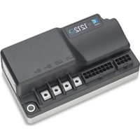
1212E - Electric motor controller CURTIS - Free user manual and instructions
Find the device manual for free 1212E CURTIS in PDF.


| Brand | Curtis |
| Model | 1212E |
| Product Type | Portable AM/FM Radio |
| Dimensions (W x H x D) | 200 x 120 x 80 mm |
| Weight | 400 g (without batteries) |
| Power Supply | 3 x AA batteries (1.5 V each) or AC adapter (not included) |
| Frequency Range AM | 520 - 1710 kHz |
| Frequency Range FM | 87.5 - 108 MHz |
| Speaker | Built-in 4 ohm, 3 W |
| Antenna | Telescopic for FM, built-in ferrite for AM |
| Controls | Volume, tuning, band selector, power |
| Display | Analog dial with frequency scale |
| Headphone Jack | 3.5 mm stereo |
| Cleaning Instructions | Wipe with a dry, soft cloth. Do not use liquids or solvents. |
| Safety Warnings | Keep away from water and heat sources. Do not disassemble. |
| Spare Parts Availability | Contact Curtis support for replacement antennas, knobs, and batteries. |
| Repairability | Basic user serviceable parts include batteries and antenna; internal repairs by qualified personnel. |
| Operating Temperature | 0°C to 40°C |
| Storage Temperature | -20°C to 60°C |
| Warranty | 1 year limited warranty |
Frequently Asked Questions - 1212E CURTIS
User questions about 1212E CURTIS
0 question about this device. Answer the ones you know or ask your own.
Ask a new question about this device
Download the instructions for your Electric motor controller in PDF format for free! Find your manual 1212E - CURTIS and take your electronic device back in hand. On this page are published all the documents necessary for the use of your device. 1212E by CURTIS.
USER MANUAL 1212E CURTIS
Brushed DC Permanent Magnet Motor Controller
Curtis Instruments, Inc.
200 Kisco Avenue
Mt. Kisco, NY 10549
www.curtisinstruments.com

Read Instructions Carefully!
Specifications are subject to change without notice. © 2024 Curtis Instruments, Inc.
® Curtis is a registered trademark of Curtis Instruments, Inc. ® Kohler is a registered trademark of Kohler Co.
© The design and appearance of the products depicted herein are the copyright of Curtis Instruments, Inc.
53250 Rev A April 2024
TABLE OF CONTENTS
CHAPTERS
1: OVERVIEW .... 1
KEY FEATURES ...... 2
TECHNICAL SUPPORT 4
CONVENTIONS......4
NUMERAL SYSTEM NOTATION....4
MISCELLANEOUS CONVENTIONS....4
2: INSTALLATION, WIRING, AND I/O CONFIGURATION 5
MOUNTING THE CONTROLLER 5
HIGH CURRENT CONNECTIONS 6
LOW CURRENT CONNECTIONS....7
8-PIN I/O CONNECTOR (J1)....7
16-PIN I/O CONNECTOR (J2) 8
WIRING DIAGRAM 9
I/Os 10
SWITCH INPUTS 10
FLEXIBLE SWITCH INPUTS....10
ANALOG INPUTS....12
POTENTIOMETER CIRCUIT 13
COIL DRIVERS 14
COIL SUPPLY 14
THROTTLE INPUT 15
FORWARD AND REVERSE INPUTS....15
KEYSWITCH....16
EMERGENCY STOP SWITCH....16
CIRCUITRY PROTECTION FUSES....16
INTERLOCK INPUT 17
EMERGENCY REVERSE INPUTS 17
TABLE OF CONTENTS CONT'D
EM BRAKE....18
MODE INPUT 18
CHARGER INHIBIT INPUT....19
I/O GROUND 19
HYDRAULIC FUNCTIONS 19
INHIBIT INPUT....21
STEERING SPEED LIMIT INPUT 22
HORN DRIVER AND INPUT 24
INCHING MODE INPUT 25
CREEP MODE INPUT 25
BDI OUTPUT 26
CAN CONNECTIONS....26
3: APPLICATION-SPECIFIC FEATURES 27
ALLOWED MAXIMUM SPEED....27
LIMITED SPEED MODE AND SPEED LIMITATION....27
SPEED LIMIT HPD 27
SPEED LIMIT SUPERVISION FOR EMERGENCY REVERSE AND INTERLOCK BRAKING....28
BATTERY PROTECTION AND BDI....28
INTERNAL BDI 29
CALIBRATE THE INTERNAL BDI 29
OVERVOLTAGE AND UNDERVOLTAGE PROTECTION 31
OVERVOLTAGE PROTECTION 32
UNDERVOLTAGE PROTECTION....32
MAIN RELAY 33
SLEEP MODE 33
PASSWORD PROTECTION 33
LOG ON TO CHANGE PARAMETERS....34
CHANGE THE PASSWORD 34
TABLE OF CONTENTS CONT'D
4: PROGRAMMING MENU PARAMETERS....35
SPEED MODE MENU 37
LOW AND HIGH SPEED ACCELERATION RATES 38
LOW AND HIGH SPEED DECELERATION RATES....39
MODE 1 AND MODE 2 MENUS....40
STEERING SPEED LIMIT MENU....41
SPEED LIMIT SUPERVISION MENU 42
THROTTLE MENU 43
THROTTLE RESPONSE PARAMETERS....45
INTERLOCK MENU 46
CURRENT MENU 47
BOOST MENU 47
MAIN RELAY MENU 48
EM BRAKE MENU....49
BATTERY MENU 50
BDI MENU 51
MOTOR MENU 52
EMERGENCY REVERSE MENU 53
INPUTS MENU....54
OUTPUTS MENU 56
GAUGE SETTINGS MENU....57
CURTIS 3150R SETTINGS MENU....57
CAN INTERFACE MENU 58
RPDO AND TPDO BYTE MAP MENUS....59
PASSWORD MENU 61
CHANGE PASSWORD MENU....62
MISC MENU....62
5: MONITOR MENU PARAMETERS....63
CONTROLLER MENU....64
STATE MENU 65
MOTOR MENU 65
TABLE OF CONTENTS CONT'D
VOLTAGE MENU 66
INPUTS MENU....67
SWITCHES MENU....68
PRIMARY SWITCHES MENU 68
SUPERVISOR INPUTS MENU....69
OUTPUTS MENU 69
6: FAULT HISTORY MENU 70
7: FAULTS, DIAGNOSTICS, AND TROUBLESHOOTING....71
PROGRAMMING DEVICE DIAGNOSTICS....71
STATUS LED 72
FAULT RECORDS....72
FAULTS....73
8: CANopen COMMUNICATIONS 83
BYTE AND BIT SEQUENCE ORDER 83
CAN PROGRAMMING CONSIDERATIONS....83
NODE IDs....83
MESSAGE CAN-IDs 84
NMT STATE CONFIGURATION 84
EMERGENCY MESSAGES AND FAULTS 84
EXPEDITED SDOs....85
PDOs 86
PDO TIMING 86
PDO MAPPING OBJECTS....86
PDO DATA BYTES 87
MAP CAN OBJECTS TO A PDO 87
CAN TILLER HEAD (RPD01, TPD01, TPD02) 88
BMS (RPD02)....90
STANDARD CANopen OBJECTS....91
ERROR HISTORY OBJECT (1003H) 91
EM BRAKE OVERRIDE OBJECT 92
BDI PERCENTAGE OBJECT 92
TABLE OF CONTENTS CONT'D
9: COMMISSIONING....93
TUNE THE THROTTLE....93
STEP 1 PREPARE THE VEHICLE 93
STEP 2 TUNE THE DEADBAND 94
STEP 3 TUNE THE THROTTLE DEMAND....94
STEP 4 CONFIRM THROTTLE OPERATION....95
STEP 5 VERIFY THE VEHICLE'S CONFIGURATION 95
SET THE SYSTEM RESISTANCE 95
TUNE VEHICLE PERFORMANCE 96
STEP 1 SET THE MAXIMUM AND MINIMUM SPEEDS ...... 96
STEP 2 SET THE ACCELERATION AND DECELERATION RATES....96
10: MAINTENANCE 98
DIAGNOSTIC HISTORY....98
APPENDIX A: VEHICLE DESIGN CONSIDERATIONS REGARDING ELECTROMAGNETIC COMPATIBILITY (EMC)....99
EMISSIONS....99
IMMUNITY 99
APPENDIX B: EN 13849 COMPLIANCE....101
APPENDIX C: CURTIS PROGRAMMING DEVICES....103
APPENDIX D: SPECIFICATIONS 105
TABLE OF CONTENTS CONT'D
TABLES
TABLE 2-1 MATING CONNECTOR PARTS: 8-PIN CONNECTOR....7
TABLE 2-2 MATING CONNECTOR PARTS: 16-PIN CONNECTOR....8
TABLE 4-1 EM BRAKE RESPONSE....50
TABLE 4-2 ALLOWED VALUES FOR SWITCH N FUNCTION PARAMETERS .... 54
TABLE 4-3 PDO MAPPING OBJECTS — CAN INDEXES ....60
TABLE 7-1 FAULT CHART .... 73
TABLE 7-2 SUPERVISOR FAULT TYPES ...... 81
TABLE 8-1 MAPPED PDO BYTES....86
TABLE 8-2 RPD01 DATA 89
TABLE 8-3 TPD01 DATA....89
TABLE 8-4 TPD02 DATA....90
TABLE 8-5 RPDO2 DATA....90
TABLE B-1 SAFETY FUNCTIONS.... 101
TABLE D-1 MODEL CHART.... 105
TABLE OF CONTENTS CONT'D
FIGURES
FIGURE 1-1 CURTIS 1212E CONTROLLER....1
FIGURE 2-1 MOUNTING DIMENSIONS .... 5
FIGURE 2-2 WIRING DIAGRAM, CURTIS 1212E CONTROLLER....9
FIGURE 2-3 STEERING ANGLES AND SPEED LIMITS 22
FIGURE 4-1 THROTTLE RESPONSE PARAMETERS 45
FIGURE 6-1 FAULT HISTORY DETAILS — CIT....70
FIGURE 6-2 FAULT HISTORY DETAILS — 1313 HANDHELD PROGRAMMER....70
FIGURE 7-1 ACTIVE FAULTS — CIT ....71
FIGURE 7-2 ACTIVE FAULTS — 1313 HANDHELD PROGRAMMER....71
The Curtis Difference

You feel it when you drive it
1 - OVERVIEW
The Curtis Model 1212E Motor Controllers provide smooth and efficient control of battery powered vehicles equipped with Brushed Permanent Magnet (PM) motors. The 1212E is optimized for use on light duty Class III pallet trucks and floor care machines such as sweepers and scrubbers.
The Model 1212E controllers are highly programmable, enabling OEMs to integrate Model 1212E controllers into any low-power PM motor application.
Figure 1-1
Curtis 1212E
Controller

KEY FEATURES
The following sections describe the controller's features.
Fit for Purpose
- Rugged housing with a small footprint for the power rating.
- Heavy-duty M4 busbars for motor and battery connectors.
- Impervious to most oils, solvents, degreasers and other chemicals often encountered by industrial vehicles.
- Tyco Mini-Universal Mate-N-Lok connectors, with an option to add sealed mating connectors.
- Internal main relay.
- Internal temperature sensor provides overtemperature and undertemperature protection.
Smooth and Secure Control
- Advanced speed regulation maintains precise speed over varied terrain, obstacles, curbs and ramps.
- Boost current feature enhances performance with transient loads, such as starting on a hill and climbing obstacles.
- Linear cutback of current ensures smooth control with no sudden loss of power during overvoltage, undervoltage or overtemperature.
• Emergency reverse inputs. - Dynamic throttle fault detection (open/short wiring fault detection).
- Adjustable EM brake holding voltage reduces heating of the brake coil.
- Hydraulic lift lockout protects the batteries from damaging levels of discharge.
- Charger inhibit input.
- Lift inhibit input.
- Inputs are protected against shorts to B+ and B−.
- Short-circuit protected outputs.
- A switchable high side driver (Coil Supply).
Flexible I/O
I/Os can be configured to provide up to:
- Five digital inputs
- Five analog inputs
• One potentiometer input - Two 1.5A coil drivers for pump contactor and lower valve
• One 1.5A coil driver for electromagnetic brake
• One 30mA horn driver
Powerful Dual Microprocessors
- Dual-microprocessor architecture achieves up to PL=c, category 2 functional safety under EN ISO 13849-1:2015 and EN 1175:2020.
- Blazing processor speeds for precise regulation of voltage and current.
Get More Out of Your Battery—Regardless of the Technology
- High-efficiency means more of your battery's energy is converted to motor output power.
- Configurable overvoltage and undervoltage protection parameters.
- Wide operating voltage range allows use with cell chemistries such as lithium ion.
- Preconfigured CANopen RPDO allows communications with BMS (Battery Management Systems) typically found on lithium battery packs.
Comprehensive CANopen Capabilities
- Plug and play support for the Curtis Model 3150 CAN display and a variety of CAN tiller heads.
• Fully CANopen compliant per CiA 301. - Preconfigured PDOs for communicating with a commander node such as a CAN tiller head.
CAN-based Programming
• Programmable over the CANbus.
• Supports most CAN-based service tools used by major industrial truck manufacturers worldwide.
- Develop, configure, optimize and debug vehicle systems with the Curtis Integrated Toolkit™.
Diagnostics
• Status LED for at-a-glance troubleshooting.
• Thermal cutback, warning and automatic shutdown provide protection to motor and controller.
- Error logging, fault history and CAN emergency messages.
Additional Features
- Two programmable speed modes (indoor/outdoor modes).
- Configurable BDI (Battery Discharge Indicator) function that allows data from the controller's internal BDI, a BMS or the CANbus.
- Creep mode for vehicles operating in narrow spaces such as containers.
- Sleep mode preserves charge by powering down the controller after a programmable period of inactivity.
- Inching mode with a programmable maximum speed allows the vehicle to move in forward or reverse when the interlock is off.
- Five flexible switch inputs that can be configured as digital or analog inputs.
- The flexible switch inputs can be used for a variety of functions, including hydraulic lift, lower valve, lift lockout, horn, creep mode and more.
Complies with Relevant US and International Regulations
For details on regulatory compliance, see the Specifications.
Note: Regulatory compliance of the complete vehicle system with the controller installed is the responsibility of the vehicle OEM.
TECHNICAL SUPPORT
For technical support, contact the Curtis distributor where you obtained your controller or the Curtis sales-support office in your region.
CONVENTIONS
The following topics describe conventions used in this manual.
Numeral System Notation
The following table describes how this manual denotes decimal, binary, and hexadecimal numbers.
Note: The letter n in the format column represents a digit.
| Numeral System Format Example | ||
| Decimal | Either of the following:• nnn• nnnd | • 127• 127d |
| Hexadecimal | Either of the following:• nnnh• 0xnnn | • 62Ah• 0x62A |
| Binary nnnb 1011b | ||
In addition, some CANopen examples have hexadecimal values without notation. Those examples are formatted with a monospace font and with the bytes delimited by spaces, as shown in the following example:
21 FF 01 11 22 01 00 00
Miscellaneous Conventions
- RO means read-only.
- RW means read-write.
- N / A means not applicable.
2 — INSTALLATION, WIRING, AND I/O CONFIGURATION
This chapter explains how to mount and wire the controller. The chapter also describes features and basic configuration for the inputs, outputs, and drivers.
MOUNTING THE CONTROLLER
To prevent external corrosion and leakage paths, mount the controller in a location that will keep the controller clean and dry. For ease of service, make sure the status LED is visible.
The controller's electronics are sealed to IP65. The environmental protection for the connectors depends upon whether sealed (IP54) or unsealed (IP40) TE Connectivity parts are used.
The following diagram shows the outline and mounting hole dimensions. To mount the controller, use the two mounting holes at the opposing corners of the heatsink. The recommended installation torque for the busbar is 1.6 ± 0.2 N.m.
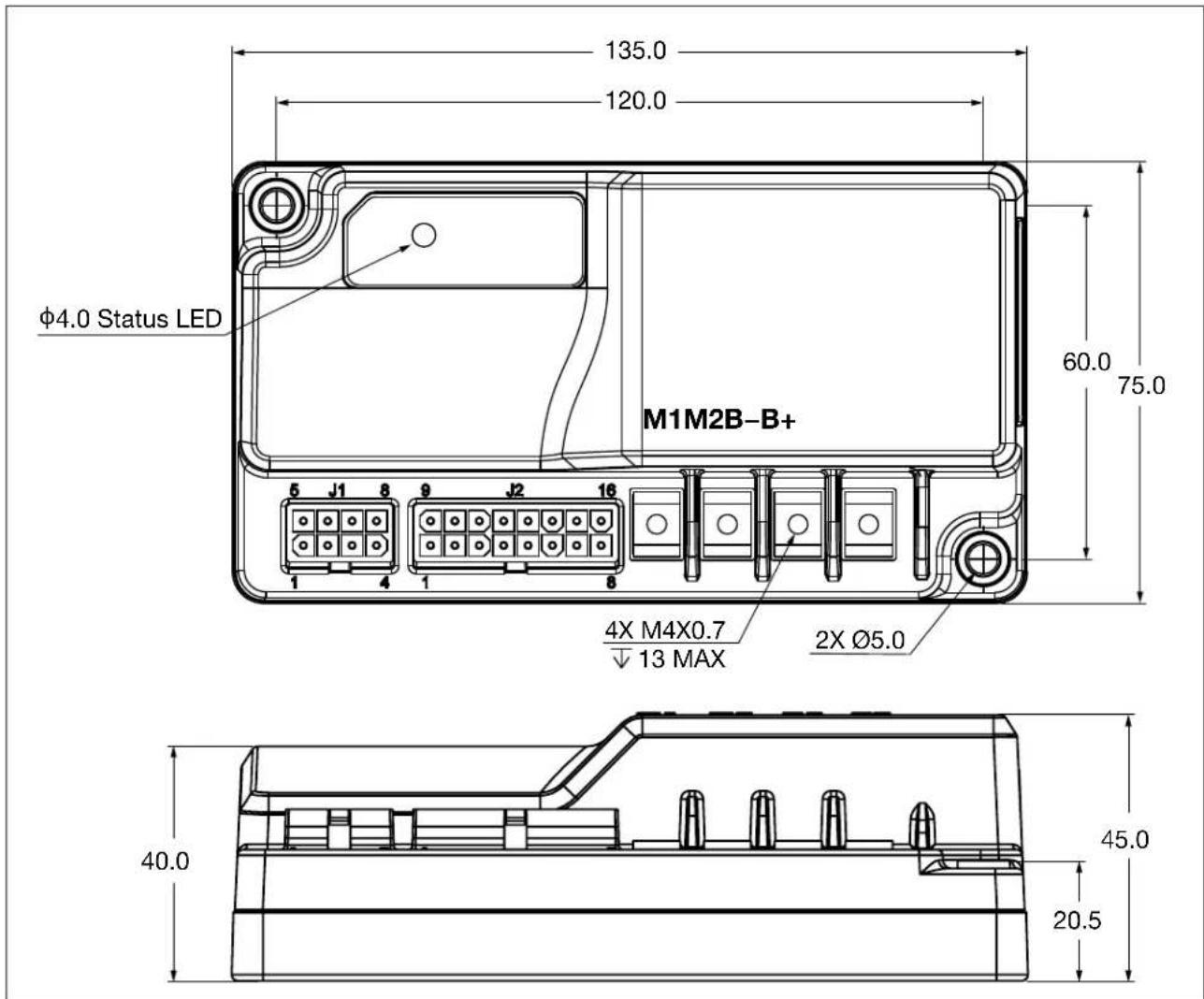
Figure 2-1 Mounting Dimensions
WARNINGS
You must heed the following warnings:
CAUTION
Working on electrical systems is potentially dangerous. Protect yourself against uncontrolled operation, high current arcs, and outgassing from lead-acid batteries:
UNCONTROLLED OPERATION — Some conditions could cause the motor to run out of control. Disconnect the motor or jack up the vehicle and get the drive wheels off the ground before attempting any work on the motor control circuitry.
HIGH CURRENT ARCS — Batteries can supply very high power, and arcing can occur if they are short circuited. Always open the battery circuit before working on the motor control circuit. Wear safety glasses and use properly insulated tools to prevent shorts.
LEAD-ACID BATTERIES — Charging or discharging generates hydrogen gas, which can build up in and around the batteries. Follow the battery manufacturer's safety recommendations. Wear safety glasses.
You will need to take steps to ensure that the vehicle system's EMC performance complies with applicable regulations. For guidelines, see Appendix A.
The controller contains ESD-sensitive components. Use appropriate precautions in connecting, disconnecting, and handling the controller.
HIGH CURRENT CONNECTIONS
The controller provides four M4X0.7 terminals for high current connections:
| Terminal Description | |
| B+ Positive | battery input |
| B− Negative | battery input |
| M1 Motor phase M1 | |
| M2 Motor phase M2 | |
Note: Positive current flows from phase M1 to phase M2, negative current flows from phase M2 to phase M1.
LOW CURRENT CONNECTIONS
The low current connections are provided by two connectors, which are described in the following topics.
8-Pin I/O Connector (J1)
The following table describes the pins on the 8-pin connector (J1):
| Pin Description | |
| J1-1 CAN L | |
| J1-2 CAN H | |
| J1-3 Switch | 1 |
| J1-4 Charger | Inhibit |
| J1-5 Switch | 5 |
| J1-6 I/O Ground | |
| J1-7 Switch | 2 |
| J1-8 Horn Driver | |
The connector can be sealed to IP54 or IP40, depending upon which TE Connectivity parts are used. The following table describes the part numbers:
Table 2-1 Mating Connector Parts: 8-Pin Connector
| Part IP54 (Sealed Connector) IP40 (Unsealed Connector) | |
| Connector TYCO #794821-1, plug TYCO #770579-1, plug | |
| Contact TYCO #770904-1 TYCO #770904-1 | |
| Interface seals TYCO #794772-8 | |
| Wire seals TYCO #794758-1 | |
| Cavity plug TYCO #794995-1 (Cavity plugs are required for unused pins.) |
16-Pin I/O Connector (J2)
The following table describes the pins on the 16-pin connector (J2):
| Pin Description | |
| J2-1 EMR NO | |
| J2-2 Switch 3 | |
| J2-3 Pot High | Note: This pin can also be used for an inhibit input or LED output. |
| J2-4 Lift Inhibit | |
| J2-5 Mode Input | |
| J2-6 Pot Wiper | |
| J2-7 Switch 4 | |
| J2-8 B+ | |
| J2-9 Reverse | |
| J2-10 Interlock | |
| J2-11 Forward | |
| J2-12 KSI (keyswitch) | |
| J2-13 Lower Driver | |
| J2-14 Lift Driver | |
| J2-15 EM Brake Driver | |
| J2-16 Coil Supply | |
The connector can be sealed to IP54 or IP40, depending upon which TE Connectivity parts are used. The following table describes the part numbers:
Table 2-2 Mating Connector Parts: 16-Pin Connector
| Part IP54 (Sealed Connector) IP40 (Unsealed Connector) | |
| Connector TYCO #794824-1, plug TYCO | #770583-1, plug |
| Contact TYCO #770904-1 TYCO #770904-1 | |
| Interface seals TYCO #1-1586362-6 | |
| Wire seals TYCO #794758-1 | |
| Cavity plug TYCO #794995-1 (Cavity plugs are required for unused pins.) |
WIRING DIAGRAM
Figure 2-2 is a representative wiring diagram. The diagram is for a walkie that has operator controls and other components directly wired to the controller.
Note: The diagram may differ from your application's requirements. However, the controller provides I/Os and programmable parameters that enable vehicle designers to meet almost any requirement. To discuss how to implement your application, contact your Curtis distributor or support engineer.

Figure 2-2
Wiring Diagram, Curtis 1212E Controller
I/Os
The following sections describe how to connect and configure I/Os.
Almost all I/Os are protected against shorts to B+ and B−. If an I/O lacks short protection, this chapter will note it.
Note: After you have wired the controller and specified the parameters that apply to the vehicle system, perform the steps in the Commissioning chapter.
Switch Inputs
The following table describes specifications for the switch inputs:
| Specification Value | |
| Low to High Threshold Depends upon the input:Pin J2-1 (EMR NO): 15.5V ±5%All other inputs: 6.5–9.0V | |
| High to Low Threshold 4.0–6.0V | |
| Open Pin Response High active | |
| Maximum Voltage 36V | |
| Maximum Reverse voltage –1V | |
| Short to B+ Protected | |
| Short to B– Protected | |
Flexible Switch Inputs
Switch inputs 1–5 are flexible switch inputs that can be used for various functions. These inputs can be used as digital switches or analog inputs. All of the flexible switch inputs can be used for the following switches:
- Creep
- Horn
- Inching forward
- Inching reverse
- Inhibit
Note: The Pot High input (J2-3) can also be used as an inhibit input by setting Pot Hi Switch Function to Inhibit 2 Input.
- Lift
- Lift lockout
- Lower
- Steering
Most of the flexible switch inputs provide one or more additional functions, as described in the following table:
| Input Additional Switches | |
| Switch 1 EMR NC (normally closed) | |
| Switch 2 EMR NC | |
| Switch 3 Belly button check | |
| Switch 4 Flex ID. See Node IDs. | |
| Switch 5 BDI output | |
Each flexible switch input has a corresponding Switch n Function parameter, where n represents the switch number. These parameters assign functions to the flexible switch inputs and are contained by the Inputs menu.
For most functions, another parameter must specify that the source of the function's data is a switch (as opposed to CAN data). In most cases, these parameters are contained in the Inputs menu and end with the word "Source".
Note: The belly button check and BDI output functions do not have parameters for input sources.
If an analog input is connected to a flexible switch input, the switch's Switch n High Threshold parameter specifies the input's high/low threshold voltage. The Switch n High Threshold parameters are contained by the Inputs menu.
Take the following steps to configure a flexible switch input:
- Connect a switch or analog input to a flexible switch input.
- Select Programming » Inputs, then perform the following steps:
2.1. Set the Switch n Function parameter to the function for which the flexible switch input will be used. For example, to use Switch 2 as the lower switch, set the Switch 2 Function parameter to Lower Switch. Note: A function can only be assigned to one input. If a function is assigned to multiple inputs, a Parameter Fault (Type 3) occurs.
2.2. For functions other than the belly button check and BDI output, specify the source of the input's data. The following table describes the parameter values to specify:
| Switch Parameter Value | ||
| Creep Creep Input Source | Creep Switch | |
| EMR NC | EMR Input Type | The value depends upon the type of switch used for the emergency reverse input:• NC Switch• NO & NC Switch |
| Horn | Horn Input Source | Horn Switch |
| Inching forward | Inching Input Source | Inching Switch |
| Inching reverse | ||
| Inhibit | Inhibit Input Source | Inhibit Switch |
| Switch Parameter Value | ||
| Lift Lift Input Source Lift | Switch | |
| Lift lockout Lift Lockout | Input Source Lift Lockout Switch | |
| Lower Lower Input Source | Lower Switch | |
| Steering Steering Input Type | This parameter is on the Steering Speed Limit menu. | The value depends upon the type of switch used for the steering input:NO Switch InputNC Switch Input |
2.3. If the input is an analog input, specify the high/low threshold voltage with the input's Switch n High Threshold parameter.
2.4. Cycle the keyswitch.
Analog Inputs
All of the flexible switch inputs can be used as analog inputs. The following table describes specifications for the analog inputs.
| Specification | Value |
| Measurement Range | 0–10V (2% accuracy) |
| Input Resistance (to B– ground) | >50kΩ |
| Time Constant | < 1 ms |
Potentiometer Circuit
The pot high and pot wiper inputs (pins J2-3 and J2-6) are for a potentiometer circuit that provides full fault protection against open or shorted wires anywhere in the circuit; the controller will generate a Throttle Fault (Type 1) if a broken wire or short is detected. The potentiometer circuit can be used for a 3-wire pot throttle or a steering angle sensor for the steering speed limit function.
Note: The Pot High input (J2-3) can also be used as an inhibit input or LED output.
Connect peripherals such as 3-wire throttle pots and steering angle sensors to the pot wiper input, pot high input and I/O ground as shown in the following diagram:
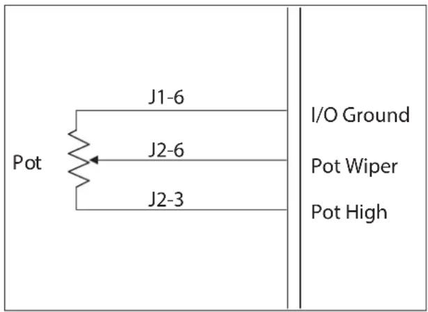
The following table describes the specifications for the pot wiper and pot high inputs:
| Specification Value | |
| Input Range 0.0–10.0V | |
| Input Impedance >100kΩ | |
| Maximum Voltage 36V | |
| Maximum Reverse Voltage –1V | |
| Short to B+ Protected | |
| Short to B– Protected |
Coil Drivers
The controller provides three low side coil drivers, which are used for the EM brake, lift, and lower functions. The coil drivers support a continuous 1.5A load and include fault diagnostics for open coils and shorts.
The following table lists the coil driver specifications:
| Specification Value | |
| Active level Low = On | |
| Maximum Current 1.5A | |
| Frequency 20 kHz | |
| Pulse Width Resolution 0.5% minimum | |
| Maximum Voltage 36V | |
| Maximum Reverse Voltage -0.5V | |
| Short to B+ Protected | |
| Short to B- Protected | |
| Open Pin Response Low/Off (pulled to B-) | |
| Logic High Threshold 7.0V | |
| Logic Low Threshold 4.5V | |
| Input Impedance > 50kΩ |
Coil Supply
The coil supply (pin J2-16) provides a dedicated high side voltage source for driving inductive loads. The coil supply is powered by the keyswitch input.
The coil supply circuit is switchable. The switched coil supply is used to provide a safe state if there is a short to ground or a low-side driver cannot be turned off. The controller provides the safe state by controlling both sides of the driver loads and cutting power to them.
The following table describes the coil supply specifications.
| Specification Value | |
| Maximum Input Current | 5A |
| Maximum Voltage 36V | |
| Maximum Reverse Voltage –36V | |
| Short to B+ Protected | |
| Short to B– Not protected |
Throttle Input
The controller supports the following types of throttles:
- 3-wire pot
• 3-wire wigwag pot
• Voltage source (0–5V)
• Wigwag voltage source (0–5V)
• CAN throttle
• CAN wigwag throttle
CAUTION
The Throttle Type parameter specifies the type of throttle with which the vehicle is equipped.
The controller provides fault protection against open or shorted wires only for pot throttles. For other throttle types, it is the responsibility of the OEM to provide any fault protection that the vehicle system requires.
The following topics describe how to connect the various types of throttles.
3-Wire Pot Throttle
If the throttle is a 3-wire pot, the circuit provides full fault protection against open or shorted wires anywhere in the throttle pot assembly.
Connect the pot to the pot high (J2-3), pot wiper (J2-6) and I/O ground (J1-6) pins. For a wiring diagram and the pot inputs' specifications, see Potentiometer Circuit.
The throttle circuit is calibrated for a 5kΩ potentiometer. If the vehicle is equipped with a non-5kΩ pot, use the Throttle Pot Calibration Enable parameter to recalibrate the circuit.
Note: If the Pot Hi Switch Function parameter specifies a value other than Pot Hi and the Throttle Type parameter specifies a 3-wire pot throttle, a Parameter Fault (Type 6) occurs.
Voltage Source Throttle
For 0–5V voltage throttles, connect the output signal to the pot wiper input. The negative side of the voltage source should reference I/O ground.
The Pot High and Pot Low parameters specify the input's voltage range. If the voltage is outside of the range, a Throttle Fault (Type 1) occurs.
CAN Throttle
For CAN throttles, the throttle demand is received by RPDO1. The CAN Throttle Min and CAN Throttle Max parameters specify the throttle's data range.
Forward and Reverse Inputs
If the vehicle is equipped with a single-ended throttle, connect the forward input to pin J2-11 and the reverse input to pin J2-9.
Note: For wigwag throttles, the driving direction is forward when the throttle input is above 50%, reverse otherwise.
If the vehicle uses a CAN throttle, the driving direction is received by RPDO1.
Keyswitch
The vehicle should have a keyswitch connected to pins J2-12 and J2-8 (B+). The keyswitch provides power for all low power circuits, including drivers and the precharge function.
The keyswitch can be used as the interlock input by setting the Interlock Type parameter to KSI Interlock.
The following table describes the keyswitch input's specifications:
| Specification Value | |
| Maximum Input Current 8A (maximum pin rating) | |
| Quiescent Current 100mA maximum | This is at full range battery voltage and does not include current draw from coil loads. |
| Voltage Accuracy ±1% | |
| Maximum Voltage 36V | |
| Maximum Reverse Voltage -36V | |
| Short to B+ Protected | |
| Short to B- Protected | |
Emergency Stop Switch
To ensure operator safety, Curtis recommends that the vehicle include an emergency stop switch. The switch, with an auxiliary contact, must be connected to the battery and keyswitch.
The Emergency Stop parameter specifies whether the vehicle is immediately stopped or decelerates to a stop.
Circuitry Protection Fuses
To protect against accidental shorts, a low current fuse, appropriately sized for the maximum current draw, should be connected in series with the B+ logic supply (pin J2-8).
A fuse is also recommended in the high power circuit from the battery to the controller's B+ terminal. This fuse will protect the power system from external shorts and should be sized appropriately for the maximum rated current of the controller.
Interlock Input
The interlock input signals whether the operator intends to drive the vehicle. The controller allows driving only when the interlock is on.
The interlock input can be either a switch, the keyswitch, or a signal received by RPDO1. The Interlock Type parameter specifies which is used.
If the vehicle is equipped with an interlock switch, connect the switch to pin J2-10.
The following considerations apply to the interlock:
- For parameters that configure the interlock input and interlock braking, see Interlock Menu.
- The interlock braking function provides a regenerative motor torque that slows the vehicle when the tiller head is released and the interlock state changes to off. To enable the interlock braking function, set the Interlock Brake Enable parameter to On.
- If the HPD Enable parameter is set to On, an HPD Sequencing fault occurs if more than 10% throttle is applied before the interlock is on.
- If all of the following conditions occur, an Interlock SRO Fault occurs:
- The keyswitch is not used as the interlock input.
- The Interlock SRO Enable parameter is set to On.
- The interlock input is on when the keyswitch is turned on.
Emergency Reverse Inputs
When emergency reverse is activated while the vehicle is driving forward, the controller produces a rapid braking force to stop the vehicle, then slowly drives the vehicle in the opposite direction.
Emergency reverse can be activated by the following inputs:
- A Normally Open (NO) switch connected to pin J2-1.
- A Normally Closed (NC) switch connected to Switch 1 (J1-3) or Switch 2 (J1-7).
- NO and NC switches used as complementary switches.
Curtis recommends using complementary switches as well as the belly button check. When complementary switches are used, the controller continually checks both switches for conditions such as shorts and broken connections.
• CAN messages received by the belly button bit of RPDO1.
If the vehicle uses an NC switch, the Switch n Function parameter that corresponds to the flexible switch input must be set to EMR NC Switch, otherwise a Parameter Fault (Type 5) will occur.
The EMR Input Type parameter specifies the emergency reverse input(s), and other Emergency Reverse parameters configure features such as acceleration and deceleration rates and the duration of emergency reverse events. See Emergency Reverse Menu.
Belly Button Check
The belly button check function generates a Hardware Fault (Type 3) if the controller detects a broken wire in the circuit for the EMR NO and EMR NC inputs.
Curtis recommends that the vehicle implement the belly button check. If the vehicle is equipped with an emergency reverse switch, implement the belly button check by taking the following steps:
-
Connect a wire to the Emergency Reverse NO (J2-1) and Switch 3 (J2-2) inputs.
-
Set the Switch 3 Function parameter to BB Check Switch.
If the vehicle uses CAN messages for emergency reverse, the belly button check signal is received by RPDO1.
EM Brake
If an electromagnetic (EM) brake is connected to the controller, pin J2-15 (EM Brake Driver) provides the EM brake driver. The EM brake should also be connected to pin J2-16 (Coil Supply).
The EM Brake Type parameter specifies the conditions that release and engage the EM brake. For information on the EM Brake parameters, see EM Brake Menu.
Note: The controller's anti-roll-forward and anti-rollback functions provide safe control when the vehicle starts or stops on hills and ramps. The anti-roll functions are enabled if the EM Brake Time parameter specifies Interlock & Neutral Type.
The driver optionally generates a Driver Fault (Type 1) for shorts and open coils. To enable the driver's fault protection, set the Fault Enable parameter to On.
If the EM brake is engaged and the motor speed is greater than the speed specified by the Fault Motor Revs parameter for 80 ms, the EMBrake Failed to Set fault occurs.
Mode Input
The controller provides two speed modes that can be configured with different minimum and maximum speeds, acceleration rates and deceleration rates. For example, one speed mode can be configured for faster outdoor driving and the other for slower indoor driving.
The mode input can be a switch connected to the controller or CAN data received by RPDO1. The Mode Input Source parameter specifies the input:
- Switch: Connect the switch to pin J2-5 and set Mode Input Source to either NO switch or NC switch.
- RPDO1: Set Mode Input Source to CAN Switch.
The following list describes the conditions that determine the active speed mode.
- If a mode switch is not connected, Mode 1 is active.
- If the mode switch is in the on position, Mode 2 is active.
- If the mode switch is in the off position, Mode 1 is active.
For information on speed mode parameters, see Speed Mode Menu.
Charger Inhibit Input
While the battery is charging, the charger inhibit function engages the EM brake and disables driving and the lift and lower drivers. Charger inhibit is activated when either pin J1–4 detects that the charger's inhibit pin is low level or RPDO2 receives a message from a BMS that indicates the battery is charging.
To use charger inhibit with a charger connected to the controller, the charger must have a dedicated inhibit pin (in addition to positive and negative pins). Connect the charger's inhibit pin to pin J1–4.
Note: The charger inhibit function automatically powers up the controller without the keyswitch on so that the BDI is tracked during charging. When the BDI reaches 100%, the controller powers down to avoid draining the battery.
I/O Ground
Pin J1-6 is for I/O ground. The following table describes the I/O ground specifications:
| Specification Value | |
| Maximum Current 8A (maximum pin rating) | |
| Maximum Voltage N/A | |
| Maximum Reverse Voltage 0V | |
| Short to B+ Not protected | |
| Short to B- Protected | |
Hydraulic Functions
The controller provides coil drivers for the lift and lower functions. The inputs for these drivers are switches connected to flexible switch inputs or commands received by RPDO1.
To configure a driver's PWM output, use the driver's Pull In and Holding Voltage parameters. These parameters are contained by the Outputs menu, which contains most of the parameters for hydraulic functions.
The pump SRO function prevents unexpected movement of the hydraulic pump and lower valve. To enable the function, set the Pump SRO Enable parameter to On. The function generates a Pump SRO Fault if any of the following conditions occur:
- The lift input is active when the controller is powered on.
- The lower input is active when the controller is powered on.
- The lift and lower signals are received by CAN, however RPDO1 did not receive a message within two seconds after the controller was powered on.
- The Lift On Interlock parameter specifies On and the lift input is active before the interlock state is on.
- The Lower On Interlock parameter specifies On and the lower input is active before the interlock state is on.
The following table describes additional conditions that forbid hydraulic operations.
| Condition Lift Action Lower Action | ||
| The lift and lower inputs are both active. Shut down Shut down | ||
| The battery is charging. Shut down Shut down | ||
| The Lift Lockout Input State is on. Shut down N/A | ||
| Traction is active and the First On Mode parameter specifies 2 (Lift & Lower). | Shut down Shut down | |
| Traction is active and the First On Mode parameter specifies 1 (Lift Only). | Shut down N/A | |
| The Lift Inhibit Input State is on. Shut down N/A | ||
| The Inhibit Input State is on. Shut down Shut down | ||
| The Interlock State is off and the Lift On Interlock parameter specifies On. | Shut down N/A | |
| The Interlock State is off and the Lower On Interlock parameter specifies On. | N/A Shut down |
Note: The states mentioned above are indicated by parameters on the Monitor menu's Inputs menu.
The controller also provides protection against open and shorted coils. If a driver's protection is enabled and an open or shorted coil is detected, the controller generates a Driver Fault and shuts down the driver. The fault type depends upon the driver. The following table lists the parameters that enable protection against open and shorted coils:
| Driver Parameter | |
| Lift Lift Driver Fault Enable | |
| Lower Lower Driver Fault Enable | |
Note: If the lift or lower driver is not used, set the Lift Driver Fault Enable or Lower Driver Fault Enable parameter to Off.
The following sections describe the inputs and drivers for the hydraulic functions.
Lift Driver and Input
Pin J2-14 is for the lift driver.
The lift input can be a switch connected to a flexible switch input, an RPDO1 bit, or both an I/O switch and the RPDO1 bit. The Lift Input Source parameter specifies the input.
If both of the following conditions are true, the controller clears the throttle and CAN lift commands, even if the First On Mode parameter specifies Off:
- The Lift Input Source parameter specifies Lift Switch and CAN Lift.
• The lift switch is active.
Lift Inhibit Input
To prevent load handling hazards, the lift inhibit function disables the lift driver if the lift inhibit input (J2-4) is active. The Lift Inhibit Input Source parameter specifies whether the input is a normally open (NO) or normally closed (NC) switch.
Lift Lockout Input
When the lift lockout input is active, the controller disables the lift driver. If lift lockout is activated during a lift operation, the lockout remains active until the lift operation has finished, after which lift operations will be disabled.
You can use the following for the lift lockout input:
- A switch connected to a flexible switch input.
Note: The lift lockout input is active high.
- RPDO1, bytes 0–1, bit 10.
- BDI percentage: The controller activates the lift lockout function when the battery's state of charge is less than or equal to the BDI level specified by the Lift Lockout Threshold parameter.
• Data transmitted by the Curtis 3150R gauge.
• A BMS (RPDO2, byte 5, bit 0).
The Lift Lockout Input Source parameter specifies the input.
Lower Driver and Input
Pin J2-13 is for the lower driver.
The lower input can be a switch connected to a flexible switch input, an RPDO1 bit, or both an I/O switch and the RPDO1 bit. The Lower Input Source parameter specifies the input.
If both of the following conditions are true, the controller clears the throttle command and CAN lower command, even if the First On Mode parameter specifies Off:
- The Lower Input Source parameter specifies Lower Switch and CAN Lower.
- The lower switch is active.
Inhibit Input
When the inhibit input is activated, the controller disables driving and the lift and lower drivers. The following table lists the inhibit input options and the parameter values that specify these options:
| Inhibit Input Parameter Value | ||
| Flexible switch input Inhibit Input Source Inhibit Switch | Note: A Switch n Function parameter must also be set to Inhibit Switch. | |
| RPDO1 Inhibit Input Source CAN Inhibit | ||
| Pot high input (pin J2-3) Pot Hi | Switch Function Inhibit 2 Input | |
Note: These parameters are contained by the Inputs menu.
Steering Speed Limit Input
The steering speed limit function limits the motor speed based on the steering angle. This provides a smoother drive when the vehicle is turning at various angles. For example, speed can be limited to 50% of the maximum speed at a 30° steering angle and to 20% at a 60° angle.
The following parameters on the Steering Speed Limit menu configure the speed limits:
- Steering Angle 1 is the angle at which the controller starts limiting the speed.
• Steering Angle 2 is the angle at which Speed Limit 1 is applied. - Speed Limit 2 is the speed limit when the angle reaches 90° .
Note: When the steering angle is between Steering Angle 1 and Steering Angle 2, the speed limit is linearly scaled between 100% (no speed limit) and Speed Limit 1. When the steering angle is between Steering Angle 2 and 90°, the speed limit is linearly scaled between Speed Limit 1 and Speed Limit 2.
Figure 2-3 shows the relationship of these parameters:

Figure 2-3 Steering Angles and Speed Limits
Note: The Steering Angle and Steering Speed Cutback parameters on the Motor submenu of the Monitor menu indicate the steering angle and speed limit in real time.
You can use any of the following as the steering speed limit input. The Steering Input Type parameter specifies which is used:
- A switch connected to a flexible switch input.
- Analog data from a steering angle sensor.
• Data transmitted by a CAN tiller head and received by RPDO1.
The following topics describe how to specify the steering speed limit input.
Steering Speed Limit Switch
If a switch input is used, when the switch state is on the vehicle speed is limited to that specified by the Speed Limit 1 parameter. To use a switch, do the following:
- Connect an NO or NC switch to a flexible switch input.
- Set the Steering Input Type parameter to either NO Switch Input or NC Switch Input.
- Assign the steering speed limit function to the flexible switch input by following the steps in the Flexible Switch Inputs section.
Note: If the Steering Input Type parameter specifies NC Switch Input but the steering speed limit function is not assigned to a flexible switch input, a Parameter Fault (Type 5) will occur.
Steering Angle Sensor
If an analog steering angle sensor is used, the controller obtains steering angle data from the pot wiper pin (J2-6). The Max Steering Left Input and Max Steering Right Input parameters define the data's effective range, and the Max Steering Angle parameter defines the maximum steering angle. The Steering Analog Input parameter indicates the analog data in real time. The following diagram shows the relationship between these parameters:

Connect the steering angle sensor to the pot wiper, pot high and I/O ground pins. For a wiring diagram and the pot inputs' specifications, see Potentiometer Circuit.
When a steering angle sensor is used, the throttle must be a CAN or CAN Wigwag throttle. If a different throttle type is specified, a Parameter Fault (Type 2) occurs.
To specify an analog input, take the following steps:
- Set the Steering Input Type parameter to one of the following values:
- Resistive throttle = Analog R Input.
-
Voltage throttle = Analog V Input.
-
Cycle the keyswitch.
-
Set the Max Steering Left Input parameter as follows:
3.1. Turn the steering device to its maximum left angle.
3.2. Get the Steering Analog Input parameter's value.
3.3. Set Max Steering Left Input to the Steering Analog Input value.
- Set the Max Steering Right Input parameter as follows:
4.1. Turn the steering device to its maximum right angle.
4.2. Get the Steering Analog Input parameter's value.
4.3. Set Max Steering Right Input to the Steering Analog Input value.
- Set the Max Steering Angle parameter to the steering device's maximum steering angle.
CAN Steering Speed Limit Input
CAN data transmitted by a CAN tiller head can be used as the steering speed limit input. The data is received by RPDO1. To use CAN data, set the Steering Input Type parameter to CAN Input.
Horn Driver and Input
Pin J1-8 is a horn driver with the following specifications:
| Specification Value | |
| Active Level Low = 0n | |
| Maximum Current 30mA | |
| Maximum Voltage 36V | |
| Maximum Reverse Voltage -0.5V | |
| Short to B+ Protected | |
| Short to B- Protected |
The horn input can be connected either to a flexible switch input or to CAN data received by RPDO1. The Horn Input Source parameter specifies which is used.
Pin J1-8 can be used to drive a horn, an external LED or a sleep mode output. The Horn Driver Output Type parameter specifies which is used.
Inching Mode Input
Inching mode allows the vehicle to move in the forward or reverse direction when the interlock state is off and the vehicle is at a standstill. When inching mode is active, the vehicle's maximum speed is limited to the Max Inching Speed.
The inching mode input can either be connected to flexible switch inputs 1 and 2 or CAN data received by RPDO1. The Inching Input Source parameter specifies which is used.
To use the flexible switch inputs, take the following steps:
- Connect the inching forward and reverse switches to flexible switch inputs.
- Set the Inching Input Source parameter to Inching Switch.
- Set the corresponding Switch n function parameters to Inching Forward Switch and Inching Reverse Switch.
Creep Mode Input
Creep mode is for situations where the vehicle is operating in a narrow space, such as a container, in which it is difficult to steer the tiller head.
In creep mode, the vehicle is reduced to the Max Creep Speed, and interlock braking is activated by the emergency reverse input. Activating creep mode changes the interlock state to on.
Creep mode can be activated when the vehicle meets all of the following conditions:
• The interlock state is off.
• The emergency reverse state is off.
- The vehicle is still.
The creep input can be either a switch connected to one of the flexible switch inputs or an RPDO1 bit.
The controller generates a Creep SRO Fault if any of the following conditions occur:
- The creep input is on when the controller is powered on.
- The creep input is on when the interlock state changes from on to off.
- The interlock input is turned on for more than 40 ms while creep mode is active.
- The controller cannot abort the creep mode braking state after the Interlock Brake Timeout expires.
BDI Output
Flexible switch input 5 can be configured as a BDI output. The output voltage ranges from 0–5V, which scales to a BDI percentage of 0–100%.
To configure Switch 5 as a BDI output, set the Switch 5 Function parameter to BDI Output.
CAN Connections
The controller implements the CANopen protocol. CAN connections use the following pins:
• CAN Low: J1-1
• CAN High: J1-2
CANbus nodes typically are wired using a daisy chain topology. Use twisted-pair wiring to minimize the likelihood of picking up a voltage bias on only one signal. If the controller is the last node in the chain, include an external 120Ω terminating resistor in the wiring harness.
Use the CAN Interface menu to specify properties such as the baud rate, node ID, emergency message rate, and heartbeat rate.
The following table describes the specifications for the CAN pins.
| Specification Value | |
| Baud Rate • Minimum: 100 kb/s | • Maximum: 1 MB/s |
| Input Impedance > 1kΩ and < 1000pF | |
| Protected Voltage -5V to 36V | |
For information on the controller's CANopen features, see CANopen Communications.
3 — APPLICATION-SPECIFIC FEATURES
Some controller features do not have corresponding I/Os. To assist the vehicle designer in the design and development process, this chapter provides information on these features.
ALLOWED MAXIMUM SPEED
The controller uses the following formula to calculate the vehicle's allowed maximum speed:
Speed Scaler * MAX(Fwd Max Speed, Rev Max Speed)
The active speed mode's Fwd Max Speed and Rev Max Speed parameters are used.
The Speed Supervision fault (Type 1) will occur if the motor speed is greater than 120% of the allowed maximum speed for more than 500 ms.
LIMITED SPEED MODE AND SPEED LIMITATION
The limited speed mode is the speed mode that has lower values for both the Fwd Max Speed and Rev Max Speed parameters (Mode 1 and Mode 2 menus). For example, if speed mode 2's Fwd Max Speed and Rev Max Speed parameter values are lower than Mode 1's Fwd Max Speed and Rev Max Speed values, mode 2 is the limited speed mode.
Note: If the Fwd Max Speed and Rev Max Speed parameters for both speed modes specify identical values, the application will not have a limited speed mode. If one mode has a higher Fwd Max Speed but a lower Rev Max Speed than the other mode, a Parameter Fault (Type 4) occurs.
The following topics describe functions related to limited speed mode.
Speed Limit HPD
To require the controller to enter the neutral state before aborting the limited speed mode, set the Speed Limit HPD parameter to On. When the speed limit HPD function is enabled and the controller is running in limited speed mode, the following inputs are affected:
| Input Description | |
| Mode The controller must be in the neutral state before the speed mode can be changed. | |
| Inhibit If the Inhibit input is on when speed limit HPD is enabled, the controller disables traction and hydraulic operations and enters the limited speed mode.To abort the limited speed mode, in addition to turning off the Inhibit input, the throttle must be released to neutral. | |
| Charger Inhibit If the Charger Inhibit input is on when speed limit HPD is enabled, the controller disables traction and hydraulic operations and enters the limited speed mode.To abort the limited speed mode, battery charging must stop and the throttle must be released to neutral. | |
Speed Limit Supervision for Emergency Reverse and Interlock Braking
When the speed limit supervision function is enabled, the vehicle is restricted by the supervision speed limit. This limit is a configurable percentage above the speed at which the vehicle is traveling when emergency reverse or interlock braking is requested.
Speed limit supervision is configured with the parameters on the Speed Limit Supervision menu. The Enable parameter enables speed limit supervision. The Speed Tolerance parameter specifies the percentage that defines the supervision speed limit. For example, if the Speed Tolerance is 20%, the supervision speed limit is 120% above the speed at which the vehicle is traveling when emergency reverse or interlock braking is requested.
BATTERY PROTECTION AND BDI
The controller provides the following methods for a battery discharge indicator (BDI):
- The controller's internal BDI. See Internal BDI.
- A battery management system (BMS) on the CANbus. See BMS (RPDO2).
- A device (other than a BMS) on the CANbus. See BDI Percentage Object.
The BDI Source parameter specifies the application's BDI method. For information on the BDI parameters, see BDI Menu.
Note: Switch 5 can be configured as a BDI output.
The following list describes terminology the manual uses when describing the BDI functions:
- BDI percentage: Indicates how charged the battery is, based on the range of voltages specified with the Empty Volts Per Cell and Full Volts Per Cell parameters.
- Cell: Several of the parameter values are expressed as volts per cell. To calculate a battery's number of cells, divide the battery's nominal voltage by 2. For example, a 36V battery has 18 cells.
The following list describes battery protection functions:
- If the BDI percentage is lower than the Low BDI Threshold parameter, the controller will generate a Low BDI fault and reduce the maximum speed to the speed specified by the Low BDI Max Speed parameter. This protects the battery against severe discharging issues.
- First-on work mode protects the battery by inhibiting the traction and lift or the traction, lift and lower from being active at the same time. The First On Mode parameter configures first-on work mode.
Note: The first-on work mode function does not prevent the operator from activating emergency reverse. When the Lift Input Source and Lower Input Source parameters specify 2, and the lift I/O switch or lower I/O switch is active, the controller inhibits traction and clears the CAN lift and lower commands regardless of the First On Mode parameter value.
- Lift lockout inhibits lift operations when the Lift Lockout Input State is on. If the Lift Lockout Input Source parameter specifies BDI as the lift lockout input, lift operations will be inhibited if the BDI percentage is below the percentage specified with the Lift Lockout Threshold parameter.
Internal BDI
The internal BDI defines full and empty battery with the Full Volts Per Cell and Empty Volts Per Cell parameters. The BDI percentage is decremented when the battery voltage is below the moving threshold for the period specified with the Battery Discharge Time parameter. The moving threshold is calculated as follows:
BDI percentage * (Full Volts Per Cell - Empty Volts Per Cell)
When a charger is connected, the BDI percentage is increased when the battery voltage is above the Start Charge Voltage parameter. The Battery Charge Time parameter specifies the charge period. If the controller is being charged, the sleep function is disabled until the BDI percentage reaches 100%.
The BDI percentage is reset to 100% if both of the following conditions are true within two seconds after the controller was powered on:
- The battery voltage is greater than the Reset Volts Per Cell parameter.
- The BDI percentage is less than the BDI Reset Percent parameter.
Calibrate the Internal BDI
Take the following steps to calibrate the internal BDI:
Step 1. Set BDI Parameters to Initial Values
Step 2. Set Full Charge Voltage
Step 3. Set Reset Volts Per Cell
Step 4. Set Full Volts Per Cell
Step 5. Set Empty Volts Per Cell
Step 6. Set Battery Discharge Time
Step 7. Set Battery Charge Time and Start Charge Voltage
Step 8. Test and Tune
Step 1 Set BDI Parameters to Initial Values
Take the following steps to set the BDI parameters to initial values:
- Select Programming » Battery » BDI.
- Set the following parameters to the following values:
| Parameter Value | |
| Full Charge Voltage 2.35V | |
| Start Charge Voltage 2.10V | |
| Reset Volts Per Cell 2.09V | |
| Full Volts Per Cell 2.04V | |
| Empty Volts Per Cell 1.73V | |
| Battery Charge Time 30 minutes | |
| Battery Discharge Time 30 minutes |
Step 2 Set Full Charge Voltage
Set the Full Charge Voltage parameter by taking the following steps:
- Plug in the charger.
- Fully charge the batteries.
- With the charger still attached and running, measure the battery voltage with a voltmeter.
- Set Full Charge Voltage to 0.02V lower than the measured voltage divided by the battery's number of cells.
Step 3 Set Reset Volts Per Cell
Set the Reset Volts Per Cell parameter by taking the following steps:
- Turn off or disconnect the charger.
- Let the batteries sit for 1 hour.
- Measure the battery voltage with a voltmeter.
- Set Reset Volts Per Cell to 0.02V lower than the measured voltage divided by the battery's number of cells.
Step 4 Set Full Volts Per Cell
Set the Full Volts Per Cell parameter by taking the following steps.
- Drive the vehicle at medium speed on a level surface for 10–15 minutes.
- Select Monitor » Voltage.
- Note the voltage indicated by the Keyswitch Voltage parameter.
- Set the Full Volts Per Cell parameter to the observed voltage divided by the battery's number of cells.
Step 5 Set Empty Volts Per Cell
The 1.73V value to which you previously set the Empty Volts Per Cell parameter should work for most batteries. However, you may need to increase the Empty Volts Per Cell value for some sealed batteries. If you are not sure, consult the battery manufacturer.
Step 6 Set Battery Discharge Time
Set the Battery Discharge Time parameter by taking the following steps:
- Drive the vehicle with a heavy load.
- Pay attention to the battery voltage, BDI percentage and time.
- Stop driving when the vehicle becomes sluggish and the battery voltage drops significantly. When that happens, you have reached the fully discharged point of the battery.
- If the BDI percentage did not reach 0% before you stopped driving, decrease the Battery Discharge Time parameter. Use the following formula to calculate the new Battery Discharge Time value:
New Battery Discharge Time = Present Battery Discharge Time * (100% - BDI%)
Step 7 Set Battery Charge Time and Start Charge Voltage
How you set the Battery Charge Time and Start Charge Voltage parameters depends upon whether the vehicle is required to support partial charging.
The typical method is to require a full recharge, which means the BDI percentage is reset only after the battery is fully charged. However, the controller can be configured to allow the operator to stop charging in mid-cycle and view a partial charge reading.
To configure these parameters, perform one of the following procedures:
• To require full charging:
- Set Battery Charge Time to 600 minutes.
- Set Start Charge Voltage equal to the Full Charge Voltage parameter's value.
• To allow partial charging:
- Set Battery Charge Time to the product of the following equation, which uses the battery's amp hour rating and the charger's average amp output:
1.5 * (Battery amp hours / Charger amps)
- Starting with the dead battery that resulted when you set the Battery Discharge Time parameter, plug in the charger.
- Charge for 10 minutes.
- Measure the battery voltage with a voltmeter.
- Set the Start Charge Voltage parameter to the measured voltage divided by the number of battery cells.
Step 8 Test and Tune
Once you have calibrated the controller's internal BDI, you'll have a good initial BDI configuration. However, for optimal BDI accuracy, test the BDI configuration for the vehicle's expected usage. Factors such as battery age, hilliness, driving surface, and user weight all impact the BDI percentage's accuracy. If testing indicates you need to fine-tune the BDI accuracy, repeat the steps in the Calibrate the Internal BDI section.
OVERVOLTAGE AND UNDERVOLTAGE PROTECTION
The controller's overvoltage and undervoltage protection consists of hardware limits that can be customized by parameters. The Battery menu contains most of the parameters that configure overvoltage and undervoltage protection.
The following table describes the hardware voltage limits:
| Nominal Voltage Brownout | Severe Undervoltage | Undervoltage Overvoltage | Severe Overvoltage | ||
| 24V | 8V | 9.6V | 16.8V | 30V | 36V |
Overvoltage Protection
Overvoltage protection works as follows:
- The allowed maximum voltage is the lesser of the Severe Overvoltage hardware limit and the voltage specified with the User Overvoltage parameter.
- If the battery voltage exceeds the allowed maximum voltage when either the vehicle is in the regenerative state or the motor voltage is more than 2V, the controller cuts back current and the Overvoltage Cutback fault occurs.
The overvoltage cutback is handled by a PID controller. The Overvoltage Cutback parameter indicates in real time how much cutback, if any, is being applied.
- If the battery voltage is 10V higher than the allowed maximum voltage, a Severe Overvoltage fault (Type 1) occurs and the controller shuts down driving.
- If the keyswitch voltage is 4V higher than the allowed maximum voltage, a Severe Overvoltage fault (Type 2) occurs and the controller shuts down driving.
Undervoltage Protection
When the battery voltage goes below the undervoltage threshold, the controller activates a closed loop proportional/integral undervoltage controller. The undervoltage controller attempts to keep the battery voltage from drooping by cutting back the drive current, thus reducing the load on the battery. The Kp UV and Ki UV parameters specify the undervoltage controller's proportional and integral gain.
Undervoltage protection works as follows:
- The allowed minimum voltage is the greater of the Severe Undervoltage hardware limit and the voltage specified with the User Undervoltage parameter.
- If the battery voltage is less than the allowed minimum voltage, the controller cuts back current and the Undervoltage Cutback fault occurs. If the cutback reaches 100%, a Severe Undervoltage fault (Type 1) occurs.
The undervoltage cutback is handled by a PID controller. You can configure the proportional and integral terms of the undervoltage controller with the Kp UV and Ki UV parameters. The Undervoltage Cutback parameter indicates how much cutback, if any, is being applied.
MAIN RELAY
The controller's main relay connects the battery to the capacitor bank. The controller engages the relay when the interlock state, creep mode state or inching mode state changes to on.
When the relay starts to engage, the controller checks for the Main Relay Welded and Main Relay Did Not Close faults. After the relay is engaged, the controller continually checks for the Main Relay Did Not Close fault.
The controller pre-charges the capacitor bank to prevent the relay contacts from arcing when the relay closes. If the capacitor bank is not sufficiently pre-charged, a Precharge Failed fault occurs.
The controller starts to disengage the relay when the interlock state, creep mode state or inching mode state changes to off and the Sequencing Delay expires. To prevent arcing between the relay contacts, the relay is disengaged when the following conditions are met:
- The armature PWM is less than 2% and the motor speed is less than 1V.
- The armature PWM or motor speed does not reach the above-mentioned values after 24 seconds.
Note: The Main Relay menu contains parameters that configure the relay.
SLEEP MODE
If sleep mode is enabled, the controller automatically powers down if the interlock or the direction inputs have been inactive for the period specified by the Sleep Time parameter.
To disable sleep mode, set Sleep Time to 0.
Note: Pin J1-8 can be configured to provide an output that indicates whether sleep mode is active.
PASSWORD PROTECTION
The password protection feature allows only authorized users to change parameter values. Password protection is available in your application if the Password Enable parameter indicates On.
The Password Enable parameter is read-only; the value is set during the manufacturing process. If your application requires the Password Enable value to be changed, contact the Curtis distributor where you obtained your controller or the Curtis sales-support office in your region.
If password protection is enabled, the Password and Change Password menus are visible. Use these parameters to log on and to change the password.
CAUTION
The default password is 0. Curtis recommends that you immediately change the default password.
The Password Status parameter on the Password menu indicates whether parameter values can be changed. Parameters can be changed only when Password Status indicates Passed.
The following topics describe how to log on and how to change the password.
Log On to Change Parameters
If the Password Status parameter indicates a value other than Passed, you must log on in order to change the parameter values. To log on, take the following steps with a Curtis programming device:
- Select Programming » Password to access the Password menu.
- Set Password Input to the password.
- Set Password Enter to On. If the password is valid, the Password Status parameter indicates Passed.
Once you have logged on, parameter values can be changed until the keyswitch is cycled.
Change the Password
To change the password, take the following steps with a Curtis programming device:
- If the Password Status parameter indicates a value other than Passed, log on as described in the previous topic.
- Select Programming » Password » Change Password to access the Change Password menu.
- Set the New Password.
- Set New Password Enter to On.
If the Password Status is Passed, the password has been successfully changed, otherwise repeat these steps.
4 — PROGRAMMING MENU PARAMETERS
SPEED MODE MENU...... p. 37
— High Speed
— Low Speed
— Keyoff Decel Rate
— Speed Limit HPD
— MODE 1/MODE 2 MENUS..... p. 40
— Fwd Max Speed
— Fwd Min Speed
— Rev Max Speed
— Rev Min Speed
— Full Accel Rate HS
— Full Accel Rate LS
— Low Accel Rate
— Neutral Decel Rate HS
— Neutral Decel Rate LS
— Full Brake Rate HS
— Full Brake Rate LS
— Low Brake Rate
— Partial Decel Rate
— STEERINGSPEED LIMIT MENU...... p. 41
— Steering Analog Input
— Steering Input Type
— Max Steering Left Input
— Max Steering Right Input
— Max Steering Angle
— Steering Angle 1
— Steering Angle 2
— Speed Limit 1
— Speed Limit 2
— SPEE D LIMIT SUPERVISION MENU...... p. 42
— Enable
— Speed Tolerance
— Speed Ramp Delay
— Speed Ramp Rate
THROTTLE MENU.... p. 43
— Throttle Type
— Pot R
— Forward Deadband
— Forward Max
— Forward Map
— Reverse Deadband
— Reverse Max
— Reverse Map
— Pot High
— Pot Low
— CAN Throttle Min
— CAN Throttle Max
— Swap Throttle Direction
— HPD Enable
— Sequencing Delay
— Throttle Pot Calibration Enable
INTERLOCK MENU.... p. 46
— Interlock Type
— Interlock SRO Enable
— Max Creep Speed
— Interlock Brake Enable
— Interlock Brake Decel Rate
— Interlock Brake Timeout
— Max Inching Speed
— Inching Time Limit
CURRENT MENU...... p. 47
— Drive Current Limit
— Regen Current Limit
— Interlock Brake Current Limit
— BOOST MENU...... p. 47
— Boost Enable
— Boost Current Limit
— Boost Time
— Boost Mode
MAIN RELAY MENU.... p. 48
— Pull In Voltage
— Holding Voltage
— Open Delay
— DNC Voltage Threshold
— Main Welded PWM
EM BRAKE MENU.... p. 49
— EM Brake Type
— Pull In Voltage
— Holding Voltage
— Fault Motor Revs
— Release Delay
— EM Brake Delay
— Fault Enable
BATTERY MENU...... p. 50
— User Overvoltage
— User Undervoltage
— Kp UV
— Ki UV
— BDI MENU.... p. 51
— BDI Source
— Full Charge Voltage
— Start Charge Voltage
— Reset Volts Per Cell
— Full Volts Per Cell
— Empty Volts Per Cell
— BDI Reset Percent
— Battery Charge Time
— Battery Discharge Time
— Low BDI Threshold
— Low BDI Max Speed
— Lift Lockout Threshold
MOTOR MENU.... p. 52
— System Resistance
— Resistance Auto Comp
— Auto Comp Current Limit
— Speed Scaler
— Current Rating
— Max Current Time
— Cutback Gain
— Stall Fault Time
EMERGENCY REVERSE MENU...... p. 53
— EMR Input Type
— EMR Current Limit
— EMR Time Limit
— EMR Speed
— EMR Accel Rate
— EMR Decel Rate
— EMR SRO Type
— EMR Interlock
INPUTS MENU...... p. 54
— Switch 1 Function
— Switch 2 Function
— Switch 3 Function
— Switch 4 Function
— Switch 5 Function
— Pot Hi Switch Function
— Switch 1 High Threshold
— Switch 2 High Threshold
— Switch 3 High Threshold
— Switch 4 High Threshold
— Switch 5 High Threshold
— Lift Input Source
— Lower Input Source
— Creep Input Source
— Mode Input Source
— Lift Lockout Input Source
— Inhibit Input Source
— Lift Inhibit Input Source
— Horn Input Source
— Inching Input Source
OUTPUTS MENU...... p. 56
— Horn Driver Output Type
— Lift Driver Fault Enable
— Lower Driver Fault Enable
— Lift Pull In Voltage
— Lift Holding Voltage
— Lower Pull In Voltage
— Lower Holding Voltage
— Lift On Interlock
— Lower On Interlock
— Lift Timeout Enable
— Lift Time Limit
— Coil Supply Enable
GAUGE SETTINGS MENU...... p. 57
— Type
— Node ID
— Timeout
— Swap Vehicle Direction
— CU RTIS 3150R SETTINGS
MENU...... p. 57
— Curtis Logo
— Hourmeter Source
— BDI Source
CAN INTERFACE MENU...... p. 58
— Baud Rate
— Heartbeat Rate
— Emergency Message Rate
— CAN NMT State
— CAN Node ID
— CAN Node ID 2
— BMS Node ID
— BMS PDO Timeout
— Auto Operational
— PDO SETUPS MENU...... p. 59
— RP D01 — RPD02 BYTE
MAP MENUS...... p. 59
— RPDO n Event Time
— RPDO n COB ID
— Length
— Map 1
— Map 2
— Map 3
— Map 4
— Map 5
— Map 6
— Map 7
— Map 8
— TP D01 — TPD02 BYTE
MAP MENUS...... p. 59
— TPDO n Event Time
— TPDO n COB ID
— Length
— Map 1
— Map 2
— Map 3
— Map 4
— Map 5
— Map 6
— Map 7
— Map 8
PASSWORD MENU...... p. 61
— Password Status
— Password Input
— Password Enter
— CHANGE PASSWORD MENU... p. 62
— New Password
— New Password Enter
MISC MENU.... p. 62
— Password Enable
— Pump SRO Enable
— First On Mode
— Sleep Time
— Emergency Stop
— Hourmeter Type
— Clear Hourmeter
— Restore Parameters
The controller provides numerous parameters that configure vehicle system performance and functionality.
The parameters are grouped into menus and described in the following topics. Each parameter is identified with a parameter name and a CAN index.
The following list describes the columns in the parameter description tables:
- Parameter and CAN Index: The parameter name and the CAN index and sub-index. If the keyswitch needs to be cycled after a parameter's value is changed, the column will include the notation “[PCF]”.
Note: When a parameter marked as [PCF] is changed, a Parameter Fault (Type 1) occurs. The fault is cleared by cycling the keyswitch. - Values and Raw Values: The allowed values as shown in Curtis programming devices and in raw units suitable for CAN.
- Data Size and Read/Write: The parameter's data size and whether the parameter is writable.
SPEED MODE MENU
The controller provides two speed modes, which are useful for driving in different conditions. For example, one speed mode can be used for outdoor driving and the other for slower indoor driving.
The parameters on the Speed Mode menu configure speed-related functions such as minimum and maximum speeds and acceleration and deceleration rates.
In addition to its parameters, the Speed Mode menu contains the Mode 1 and Mode 2 menus. These menus include several acceleration rate and deceleration rate parameters whose names end with "HS" or "LS". The controller applies the "HS" rates when the speed reaches that specified by the High Speed parameter, and applies the "LS" rates when the speed reaches that specified by the Low Speed parameter. See Low and High Speed Acceleration Rates and Low and High Speed Deceleration Rates.
The Speed Mode menu contains the following menus:
- Mode 1
- Mode 2
- Steering Speed Limit
• Speed Limit Supervision
The following table describes the parameters on the Speed Mode menu.
SPEED MODE MENU
| PARAMETERCAN INDEX | VALUESRAW VALUES | DATA SIZEREAD/WRITE DESCRIPTION | |
| High Speed0x3824:00 | 0–100%0–32767 | 16-bitRW | Specifies the percentage of the motor's maximum speed above which the high speed (“HS”) parameters are used. |
| Low Speed0x3825:00 | 0–100%0–32767 | 16-bitRW | Specifies the percentage of the motor's maximum speed below which the low speed (“LS”) parameters are used. |
| Keyoff Decel Rate0x382A:00 | 0.2–0.8s100–400 | 16-bitRW | Specifies the rate at which the vehicle decelerates at key-off. |
| Speed Limit HPD0x3909:00 | Off/On0–1 | 8-bitRW | Specifies whether the controller must enter the neutral state before limited speed mode can be aborted. See Speed Limit HPD. |
Low and High Speed Acceleration Rates
The Full Accel Rate HS and Full Accel Rate LS parameters on the Mode 1 and Mode 2 menus configure acceleration rates for low and high speeds. When throttle is applied while the vehicle is traveling between the specified low and high speeds, the acceleration rate is linearly scaled between the low and high acceleration rates. These acceleration rates apply to both forward and reverse.
The following diagram describes the parameters that configure the acceleration rate:

- When the speed is below Low Speed, the vehicle accelerates at the rate specified by Full Accel Rate LS.
- When the speed is between Low Speed and High Speed, the acceleration rate is linearly scaled between Full Accel Rate LS and Full Accel Rate HS.
- When the speed is above High Speed, the acceleration rate is specified by Full Accel Rate HS.
For steps on configuring acceleration and deceleration rates, see Set the Acceleration and Deceleration Rates.
Low and High Speed Deceleration Rates
The Full Brake Rate HS and Full Brake Rate LS parameters on the Mode 1 and Mode 2 menus configure deceleration rates for low and high speeds. When the vehicle is traveling between the specified low and high speeds and full throttle is applied in the opposite direction, the deceleration rate is linearly scaled between the low and high speed rates. The deceleration rates apply to forward and reverse.
The following diagram describes the parameters that configure the deceleration rate:
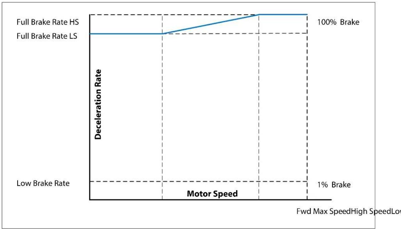
- When the speed is below Low Speed, the vehicle decelerates at the rate specified by Full Brake Rate LS.
- When the speed is between Low Speed and High Speed, the deceleration rate is linearly scaled between Full Brake Rate LS and Full Brake Rate HS.
- When the speed is above High Speed, the deceleration rate is specified by Full Brake Rate HS.
Mode 1 and Mode 2 Menus
Use the Mode 1 and Mode 2 menus to configure speed modes 1 and 2. Both menus contain parameters with the same names, so the following table describes both menus' parameters. The first column contains the CAN indexes for both modes.
Note: The percentage-based parameters are percentages of the motor's maximum speed.
SPEED MODE — MODE 1 AND MODE 2 MENUS
| PARAMETERCAN INDEX | VALUESRAW VALUES | DATA SIZEREAD/WRITE DESCRIPTION | |
| Fwd Max Speed0x3800:000x3807:00 | 0-100%0-32767 | 16-bitRW | Specifies the maximum forward speed. |
| Fwd Min Speed0x3801:000x3808:00 | 0-100%0-32767 | 16-bitRW | Specifies the minimum forward speed. |
| Rev Max Speed0x3802:000x3809:00 | 0-100%0-32767 | 16-bitRW | Specifies the maximum reverse speed. |
| Rev Min Speed0x3803:000x380A:00 | 0-100%0-32767 | 16-bitRW | Specifies the minimum reverse speed. |
| Full Accel Rate HS0x3812:000x381B:00 | 0.1s-12.0s50-6000 | 16-bitRW | Specifies the rate at which the vehicle accelerates when full throttle is applied at high vehicle speeds. Larger values represent slower response.See Low and High Speed Acceleration Rates. |
| Full Accel Rate LS0x3813:000x381C:00 | 0.1s-12.0s50-6000 | 16-bitRW | Specifies the rate at which the vehicle accelerates when full throttle is applied at low vehicle speeds. Larger values represent slower response. |
| Low Accel Rate0x3819:000x3822:00 | 0.1s-12.0s50-6000 | 16-bitRW | Specifies the rate at which the vehicle accelerates when a small amount of throttle is applied.Adjust this parameter if you need to tune the vehicle for low speed maneuverability. |
| Neutral Decel Rate HS0x3814:000x381D:00 | 0.1s-12.0s50-6000 | 16-bitRW | Specifies the rate at which the vehicle decelerates when the throttle is released to neutral at high speed. |
| Neutral Decel Rate LS0x3815:000x381E:00 | 0.1s-12.0s50-6000 | 16-bitRW | Specifies the rate at which the vehicle decelerates when the throttle is released to neutral at low speed. |
| Full Brake Rate HS0x3816:000x381F:00 | 0.1s-12.0s50-6000 | 16-bitRW | Specifies the rate at which the vehicle decelerates from high speeds when full throttle is applied in the opposite direction. |
| Full Brake Rate LS0x3817:000x3820:00 | 0.1s-12.0s50-6000 | 16-bitRW | Specifies the rate at which the vehicle decelerates from low speeds when full throttle is applied in the opposite direction. |
| Low Brake Rate0x381A:000x3823:00 | 0.1s-12.0s50-6000 | 16-bitRW | Specifies the rate at which the vehicle decelerates when a small amount of throttle is applied in the opposite direction. |
| Partial Decel Rate0x3818:000x3821:00 | 0.1s-12.0s50-6000 | 16-bitRW | Specifies the rate at which the vehicle decelerates when the throttle is reduced without being released to neutral.Larger values provide a slower response. |
Steering Speed Limit Menu
The Steering Speed Limit parameters configure the steering speed limit function. The following table describes the parameters.
SPEED MODE — STEERING SPEED LIMIT MENU
| PARAMETERCAN INDEX | VALUESRAW VALUES | DATA SIZEREAD/WRITE DESCRIPTION | |
| Steering Analog Input0x384C:00 | 0–100%0–1000 | 16-bitRO | Indicates the steering sensor's analog data. The data applies if the steering input is an analog input. |
| Steering Input Type0x3841:00 | Enumerated0–5 | 8-bitRW | Specifies the steering speed limit input:0 = None1 = NO Switch Input2 = NC Switch Input3 = Analog R Input4 = Analog V Input5 = CAN Input |
| Max Steering Left Input0x3842:00 | 0–100%0–1000 | 16-bitRW | Specifies the analog data that indicates the tiller head is at its maximum left angle.This parameter applies only to analog inputs. |
| Max Steering Right Input0x3843:00 | 0–100%0–1000 | 16-bitRW | Specifies the analog data that indicates the tiller head is at its maximum right angle.This parameter applies only to analog inputs. |
| Max Steering Angle0x384B:00 | 0–90°0–16383 | 16-bitRW | Specifies the maximum steering angle for the left and right sides. |
| Steering Angle 10x3844:00 | 0–90°0–16383 | 16-bitRW | Specifies the steering angle at which the controller starts limiting the speed. |
| Steering Angle 20x3845:00 | 0–90°0–16383 | 16-bitRW | Specifies the steering angle at which the Speed Limit 1 parameter's speed is applied. |
| Speed Limit 10x3846:00 | 0–100%0–32767 | 16-bitRW | Depends upon whether the steering input is an NO or NC switch:NO or NC switch: Specifies the speed limit when the switch is on.Other input types: Specifies the speed limit when the steering angle is at Steering Angle 2. |
| Speed Limit 20x3847:00 | 0–100%0–32767 | 16-bitRW | Specifies the speed limit when the steering angle is at 90°. This parameter is not used if the steering input is an NO or NC switch. |
Speed Limit Supervision Menu
The Speed Limit Supervision parameters configure whether and how speed is limited for emergency reverse and interlock braking operations. For more information, see Speed Limit Supervision for Emergency Reverse and Interlock Braking.
SPEED MODE — SPEED LIMIT SUPERVISION MENU
| PARAMETERCAN INDEX | VALUESRAW VALUES | DATA SIZEREAD/WRITE DESCRIPTION | |
| Enable0x3910:00 | Off/On0-1 | 8-bitRW | Specifies whether speed limit supervision is enabled.CAUTION: Specifying Off may make the system non-compliant with EN 1175:2020 and may cause a higher probability of dangerous failure. Regulatory compliance of the complete vehicle system, including this setting, is the responsibility of the vehicle OEM. |
| Speed Tolerance0x3911:00 | 0-100%0-32767 | 16-bitRW | Specifies the percentage portion of the supervision speed limit, which is calculated as follows:1 + Speed Tolerance |
| Speed Ramp Delay0x3912:00 | 100-2000 ms100-2000 | 16-bitRW | Specifies the interval between when the speed limit is exceeded and when speed must begin decreasing. |
| Speed Ramp Rate0x3913:00 | 100-500%1024-5120 | 16-bitRW | Specifies the slowest allowable ramp transition from the maximum speed to zero. |
THROTTLE MENU
Use the Throttle menu to specify the type of throttle used by the vehicle and to configure the throttle. The following table describes the Throttle parameters.
Note: The Forward and Reverse Deadband, Max, and Map parameter values are percentages of the throttle's maximum wiper voltage.
THROTTLE MENU
| PARAMETERCAN INDEX | VALUESRAW VALUES | DATA SIZEREAD/WRITE DESCRIPTION | |
| Throttle Type [PCF]0x3340:00 | Enumerated0-5 | 16-bitRW | Specifies the throttle type:0 = 3 Wire Pot1 = 3 Wire Pot Wigwag2 = 0-5V Throttle3 = 0-5V Throttle Wigwag4 = CAN Throttle5 = CAN Throttle Wigwag |
| Pot R0x334A:00 | 800Ω-15000Ω800-15000 | 16-bitRW | Specifies the throttle pot's resistance. |
| Forward Deadband0x3341:00 | 0-100%0-1000 | 16-bitRW | Specifies the wiper voltage at the deadband threshold while the vehicle is moving forward. |
| Forward Max0x3342:00 | 0-100%0-1000 | 16-bitRW | Specifies the wiper voltage that generates 100% controller output while the vehicle is moving forward. |
| Forward Map0x3343:00 | 0-100%0-32767 | 16-bitRW | Specifies the controller output that is generated when the throttle input is at 50% while the vehicle is moving forward.Following are guidelines for setting Forward Map:50% provides a linear output response to the throttle input.Values below 50% reduce the controller output at low throttle positions, providing enhanced slow speed maneuverability.Values above 50% give the vehicle a faster, more responsive feel at low throttle positions.For more information, see Throttle Response Parameters. |
| Reverse Deadband0x3344:00 | 0-100%0-1000 | 16-bitRW | These parameters work just like the corresponding Forward parameters, except that they apply while the vehicle is moving in reverse. |
| Reverse Max0x3345:00 | 0-100%0-1000 | 16-bitRW | |
| Reverse Map0x3346:00 | 0-100%0-32767 | 16-bitRW | |
| Pot High0x3356:00 | 3.0-10.0V2457-8190 | 16-bitRW | Specifies the maximum voltage for voltage throttles.If the throttle voltage is outside the range defined by Pot Low and Pot High, a Throttle Fault (Type 1) occurs. |
| Pot Low0x3357:00 | 0-3.0V0-2457 | 16-bitRW | Specifies the minimum voltage for voltage throttles. |
| CAN Throttle Min0x3347:00 | -32768 to 32767-32768 to 32767 | 16-bitRW | Specifies the minimum throttle request for CAN throttles.If the throttle request is outside the range defined by CAN Throttle Min and CAN Throttle Max, a Throttle Fault (Type 1) occurs. |
| CAN Throttle Max0x3348:00 | -32768 to 32767-32768 to 32767 | 16-bitRW | Specifies the maximum throttle request for CAN throttles. |
THROTTLE MENU, cont'd
| PARAMETERCAN INDEX | VALUESRAW VALUES | DATA SIZEREAD/WRITE DESCRIPTION | |
| Swap Throttle Direction [PCF]0x335B:00 | Off/On0-1 | 8-bitRW | Changes the throttle direction to the opposite direction. For example, if you toggle this value for a single-ended throttle, the forward input would become the reverse input, and vice versa. |
| HPD Enable [PCF]0x334B:00 | Off/On0-1 | 8-bitRW | Indicates whether the HPD feature is enabled.When HPD is enabled, a fault occurs if the Throttle Demand exceeds 10% when the interlock is turned on and the Sequencing Delay expires.The fault depends upon how long this interlock/throttle demand state exists:48 ms: HPD Sequencing fault10s: Throttle Fault (Type 2)CAUTION: Specifying Off may make the system non-compliant with EN 1175:2020 and may cause a higher probability of dangerous failure. Regulatory compliance of the complete vehicle system, including this setting, is the responsibility of the vehicle OEM. |
| Sequencing Delay0x334C:00 | 40-2000 ms10-500 | 16-bitRW | Specifies the time during which the interlock input, creep mode input or inching mode input can cycle before the HPD-related faults occur.A delay is useful for cases where the input is momentarily cycled, such as when an operator briefly bounces off the seat. In such cases, the vehicle typically should continue moving. |
| Throttle Pot Calibration Enable0x4F06:00 | Off/On0-1 | 16-bitRW | Calibrates the throttle. The throttle circuit by default is calibrated for a 5kΩ pot. If a non-5kΩ pot is used, take the following steps to calibrate the throttle circuit:Set Pot R to the potentiometer's resistance.Connect the potentiometer's pot high and ground to the controller, with the pot wiper floating.Set Throttle Pot Calibration Enable to On. This calibrates the throttle circuit. |
Throttle Response Parameters
The Forward/Reverse Deadband, Forward/Reverse Max, and Forward/Reverse Map parameters specify the throttle demand that is generated by the throttle position. The following diagram shows how these parameters work:
Figure 4-1
Throttle Response
Parameters
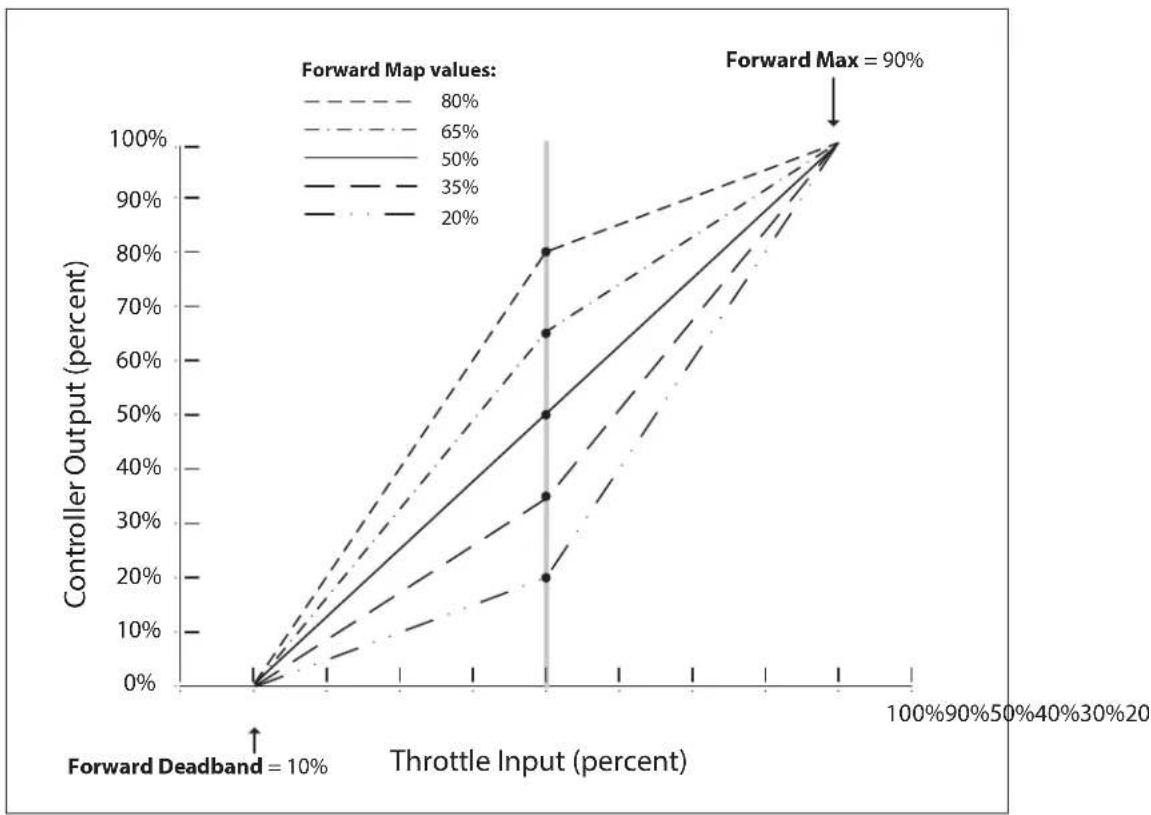
When the throttle input reaches 50%, the controller output depends upon the Forward Map parameter. For example, if Forward Map is 80%, the controller output is 80% when the throttle input is 50%.
INTERLOCK MENU
The following table describes the interlock parameters.
INTERLOCK MENU
| PARAMETERCAN INDEX | VALUESRAW VALUES | DATA SIZEREAD/WRITE DESCRIPTION | |
| Interlock Type [PCF]0x34B0:00 | Enumerated0-2 | 8-bitRW | Specifies the source of theinterlock input:0 = Interlock Switch1 = KSI Interlock2 = CAN Interlock |
| Interlock SRO Enable0x34B3:00 | Off/On0-1 | 8-bitRW | Indicates whether the interlock SRO function is enabled when Interlock Type is not set to KSI Interlock.If interlock SRO is enabled, an Interlock SRO Fault occurs if the interlock state is on when the keyswitch is turned on. |
| Max Creep Speed0x34B2:00 | 0-100%0-32767 | 16-bitRW | Specifies the maximum speed when the vehicle is in creep mode.The value is a percentage of the speed mode's maximum speed. |
| Interlock Brake Enable0x34B5:00 | Off/On0-1 | 8-bitRW | Specifies whether interlock braking is activated when the interlock signal is turned off:On = The controller uses regen braking to stop the vehicle.Off = The EM brake engages after theSequencing Delay expires. |
| Interlock Brake Decel Rate0x34B6:00 | 0.1-8.0s50-4000 | 16-bitRW | Specifies the rate at which the vehicle brakes to a stop when interlock braking is activated. |
| Interlock Brake Timeout0x34B7:00 | 0.2-8.0s25-1000 | 16-bitRW | Specifies the maximum duration of an interlock braking event. |
| Max Inching Speed0x34B8:00 | 0-100%0-32767 | 16-bitRW | Specifies the maximum speed wheninching modeis active. |
| Inching Time Limit0x34B9:00 | 0-120s0-120 | 16-bitRW | Specifies the maximum duration of an inching mode operation. |
CURRENT MENU
The following table describes the Current menu's parameters.
Note: The Current menu also contains the Boost menu.
CURRENT MENU
| PARAMETERCAN INDEX | VALUESRAW VALUES | DATA SIZEREAD/WRITE DESCRIPTION | |
| Drive Current Limit0x3440:00 | 10–90A40–360 | 16-bitRW | Specifies the maximum current the controller supplies to the motor during driving. |
| Regen Current Limit0x3441:00 | 10–90A40–360 | 16-bitRW | Specifies the maximum current the controller supplies to the motor during regenerative braking. |
| Interlock Brake Current Limit0x3444:00 | 10–90A40–360 | 16-bitRW | Specifies the maximum current the controller supplies to the motor during interlock braking.When interlock braking is active, the current limit is specified by whichever of the following parameters is set to the higher current limit:Interlock Brake Current LimitRegen Current Limit |
Boost Menu
The following table describes the parameters on the Boost menu.
CURRENT MENU — BOOST MENU
| PARAMETERCAN INDEX | VALUESRAW VALUES | DATA SIZEREAD/WRITE DESCRIPTION | |
| Boost Enable0x3433:00 | 0ff/0n0-1 | 8-bitRW | Enables or disables the boost current function.Boost current provides a brief increase of current to improve performance with transient loads such as starting on a hill, crossing a threshold, and climbing obstacles. |
| Boost Current Limit0x3442:00 | 10-90A40-360 | 16-bitRW | Specifies the maximum current the controller supplies to the motor during a boost current operation. |
| Boost Time0x3435:00 | 1-10s63-625 | 16-bitRW | Specifies the maximum duration of a boost current operation. |
| Boost Mode0x343F:00 | Enumerated0-1 | 8-bitRW | Specifies the condition that re-enables the boost current function after a boost current operation has ended:0 = Restart on KSI. Cycle the keyswitch. (The throttle does not need to be released to neutral.)1 = Restart on Neutral. Release the throttle to neutral. |
MAIN RELAY MENU
The following table describes the parameters on the Main Relay menu.
Note: For information on the controller's internal relay, see Main Relay.
MAIN RELAY MENU
| PARAMETERCAN INDEX | VALUESRAW VALUES | DATA SIZEREAD/WRITE DESCRIPTION | |
| Pull In Voltage0x34C8:00 | 0–100%0–4096 | 16-bitRW | Specifies the initial voltage of the relay when the driver is first turned on.The controller allows a high initial voltage to ensure the relay closes. The voltage then decreases to the Holding Voltage. |
| Holding Voltage0x34C6:00 | 0–100%0–4096 | 16-bitRW | Specifies the voltage the controller applies to the relay coil after the relay closes.Set Holding Voltage high enough so that the relay remains closed under all shock and vibration conditions that the vehicle is expected to encounter. |
| Open Delay0x34CA:00 | 0.0–40.0s0–10000 | 16-bitRW | Specifies how long the relay should remain closed after the interlock input has been opened.A delay prevents unnecessary cycling of the relay. |
| DNC Voltage Threshold0x34CB:00 | 0.5V–10.0V50–1000 | 16-bitRW | Specifies the maximum voltage difference allowed between the keyswitch and capacitor bank voltages.If this voltage difference is exceeded for 96 ms, a Main Relay Did Not Close fault occurs. |
| Main Welded PWM0x3540:00 | 8–20%2621–6554 | 16-bitRW | Specifies the PWM the controller applies to the motor to check for the Main Relay Welded fault. |
EM BRAKE MENU
The following table describes the parameters on the EM Brake menu.
EM BRAKE MENU
| PARAMETERCAN INDEX | VALUESRAW VALUES | DATA SIZEREAD/WRITE DESCRIPTION | |
| EM Brake Type [PCF]0x3479:00 | Enumerated0-2 | 8-bitRW | Specifies how the electromagnetic brake responds to the interlock input, throttle, and motor speed:0 = EM Brake Disable. This is for vehicles that are not equipped with an EM brake.Note: When EM Brake Disable is specified, the EM brake function can be commanded by CAN. SeeEM BrakeOverride Object.1 = Interlock Type.2 = Interlock & Neutral Type. This value enables the anti-roll functions.For information on the EM brake's engage and release conditions, seeTable 4-1. |
| Pull In Voltage0x3473:00 | 20-100%51-255 | 8-bitRW | Specifies the EM braking system's initial voltage when the EM brake is activated.To ensure that the EM brake is released, the controller allows a high initial voltage when the EM brake is activated. This peak voltage then decreases to the Holding Voltage. |
| Holding Voltage0x3472:00 | 20-100%51-255 | 8-bitRW | Specifies the reduced voltage the controller applies to the brake coil once the brake has been released.Set the Holding Voltage high enough so that the brake remains released under all shock and vibration conditions that the vehicle is expected to encounter. |
| Fault Motor Revs0x3471:00 | 0.50-3.00V50-300 | 16-bitRW | Specifies the maximum allowed speed after the EM brake has been engaged.If the motor speed exceeds the specified value for 80 ms with the EM brake engaged, an EM Brake Failed To Set fault occurs. |
| Release Delay0x3474:00 | 40-2000 ms5-250 | 16-bitRW | Specifies how long it takes the controller to release the EM brake when the controller output increases above 0%.If the delay is too short, the vehicle could roll back when the EM brake is released. |
| EM Brake Delay0x3475:00 | 0.0-2.0s0-250 | 16-bitRW | Specifies how long it takes for the controller to engage the EM brake when the controller output decreases to 0%.To ensure the vehicle doesn't move before the brake fully engages, the delay should be longer than the actual brake setting time. |
| Fault Enable0x3403:00 | Off/On0-1 | 8-bitRW | Enables or disables whether the controller generates a Driver Fault (Type 1) if one of the following conditions occurs:Missing brake coilShorted brake coilCoil driver damage |
The following table describes the conditions that cause the controller to release and engage the EM brake when EM braking is enabled.
Table 4-1 EM Brake Response
| EM Brake Type Parameter Release Engage | ||
| Interlock Type When all of the following conditions occur:The main relay is engaged.The interlock state is on.The Release Delay has expired. | Depends upon whether the Interlock Brake Enable parameter is On or Off:On: Depends upon the motor speed:- If the motor speed is greater than 1.00V, the controller regen brakes the vehicle to a stop and then engages the EM brake.- If the motor speed is less than 1.00V, the EM brake engages after the Sequencing Delay expires.Off: Engages when the Sequencing Delay expires. | |
| Interlock & Neutral Type When all of the following conditions occur:The main relay is engaged.The interlock state is on.The throttle is out of neutral.The Release Delay has expired. | When either of the following conditions occurs:The throttle command is zero and the motor speed is less than 1.00V.The throttle command is zero and the EM Brake Delay expires, regardless of the motor speed. | |
BATTERY MENU
The Battery menu parameters configure overvoltage and undervoltage protection. The menu also contains the BDI menu. The following table describes the parameters on the Battery menu.
BATTERY MENU
| PARAMETERCAN INDEX | VALUESRAW VALUES | DATA SIZEREAD/WRITE DESCRIPTION | |
| User Overvoltage0x33A2:00 | 105–150%1075–1536 | 16-bitRW | Specifies the overvoltage threshold. The value is a percentage of the battery's nominal voltage. |
| User Undervoltage0x33A3:00 | 40–95%410–973 | 16-bitRW | Specifies the undervoltage threshold. The value is a percentage of the battery's nominal voltage. |
| Kp UV0x338B:00 | 0.0–100.0%0–1024 | 16-bitRW | Specifies the undervoltage controller's proportional gain. The value is the desired percentage of cutback per volt. Higher values provide tighter control.Note:Typically, the Kp UV and Ki UV parameters are configured together to provide the best response. To specify a linear response, set Ki UV to 0%. |
| Ki UV0x3389:00 | 0–100%0–16384 | 16-bitRW | Specifies the undervoltage controller's integral gain. Higher values provide tighter control. |
BDI Menu
The BDI menu contains parameters for configuring the controller's internal BDI. For more information, see Battery Protection and BDI.
BATTERY MENU — BDI MENU
| PARAMETERCAN INDEX | VALUESRAW VALUES | DATA SIZEREAD/WRITE DESCRIPTION | |
| BDI Source0x33AC:00 | Enumerated0-2 | 8-bitRW | Specifies the BDI data source:0 = Internal BDI1 = CAN BDINote:The CAN BDI data is received by the BDI Percentage object.2 = BMS BDI |
| Full Charge Voltage0x339B:00 | 0.900-3.000V900-3000 | 16-bitRW | Specifies the voltage above which the controller considers the battery as having finished charging. |
| Start Charge Voltage0x339C:00 | 0.900-3.000V900-3000 | 16-bitRW | Specifies the voltage above which the controller considers the battery as starting to charge. |
| Reset Volts Per Cell0x33A0:00 | 0.900-3.000V900-3000 | 16-bitRW | Specifies the battery voltage above which the controller resets the BDI percentage to 100% if both of the following conditions are true within two seconds after the controller was powered on:The battery voltage is greater than the Reset Volts Per Cell parameter.The BDI percentage is less than the BDI Reset Percent parameter.Specify a voltage that is higher than the Full Volts Per Cell voltage. |
| Full Volts Per Cell0x339E:00 | 0.900-3.000V900-3000 | 16-bitRW | Specifies the battery cell voltage at which the battery is considered 100% charged. |
| Empty Volts Per Cell0x339D:00 | 0.900-3.000V900-3000 | 16-bitRW | Specifies the battery cell voltage at which the battery is considered 0% charged. |
| BDI Reset Percent0x33A6:00 | 0-100%0-100 | 8-bitRW | Specifies the percentage of battery voltage below which the controller will reset the BDI percentage to 100% if the conditions described in the Reset Volts Per Cell parameter description are met.When a battery has a high BDI percentage, its float voltage when the keyswitch is powered on could cause false BDI resets. The BDI Reset Percent parameter lets you preempt this problem by specifying a minimum threshold for resetting the percentage. |
| Battery Charge Time0x33A1:00 | 1-600 minutes1-600 | 16-bitRW | Specifies how many minutes it takes for the BDI percentage to increase from 0% to 100% while the battery is being charged.Higher battery amp/hour ratings require a larger Battery Charge Time. |
| Battery Discharge Time0x339F:00 | 1-600 minutes1-600 | 16-bitRW | Specifies the period of time during which the battery voltage must be below the moving threshold before the controller will decrement the BDI percentage. |
| Low BDI Threshold0x33AA:00 | 0-100%0-100 | 8-bitRW | Specifies the BDI percentage at or below which the Low BDI fault occurs. |
| Low BDI Max Speed0x33AE:00 | 20-80%6554-26214 | 16-bitRW | Specifies the speed limit the controller will apply if a Low BDI fault occurs. |
| Lift Lockout Threshold0x33A9:00 | 0-100%0-100 | 8-bitRW | Specifies the BDI percentage at or below which the controller disables the lift driver to prevent battery damage. |
MOTOR MENU
The following table describes the Motor menu's parameters.
MOTOR MENU
| PARAMETERCAN INDEX | VALUESRAW VALUES | DATA SIZEREAD/WRITE DESCRIPTION | |
| System Resistance0x3513:00 | 10–800mΩ10–800 | 16-bitRW | Specifies the resistance that the controller uses for load compensation and speed estimation.The controller's performance depends upon an accurate System Resistance value. To calculate the correct value, seeSet the System Resistance.Note:The system resistance is the overall amount of resistance for the motor, brushes, wiring, and connections. The motor temperature also affects the system resistance. |
| Resistance Auto Comp0x3514:00 | Off/On0–1 | 16-bitRW | Specifies whether the controller automatically measures motor resistance before the brake is released.Motor resistance plays an important role in how the controller calculates the speed. If Resistance Auto Comp is enabled, the automatic measuring of resistance increases the accuracy of speed calculations. |
| Auto Comp Current Limit0x3515:00 | 5–50%1638–16384 | 16-bitRW | Sets the current limit the controller uses to measure motor resistance automatically.The value is a percentage of theDrive Current Limitparameter. |
| Speed Scaler0x3516:00 | 15.00–30.00V1500–3000 | 16-bitRW | Specifies the maximum voltage that the controller can apply to the motor. Speed Scaler is used to define theallowed maximum speed. |
| Current Rating0x3548:00 | 5A–50A20–200 | 16-bitRW | Specifies the motor's current rating. Use the rating provided by the motor's manufacturer. |
| Max Current Time0x3549:00 | 0–120s0–120 | 16-bitRW | Specifies how long the motor runs at full current if the motor overheats. The controller cuts back current after this timeout expires. |
| Cutback Gain0x354A:00 | 0–100%0–255 | 16-bitRW | Specifies how quickly the controller cuts back current if the motor has overheated and the Max Current Time has expired.Higher values provide a quicker cutback. |
| Stall Fault Time0x3510:00 | 0–32s0–8000 | 16-bitRW | Specifies how long the controller must detect the motor as not moving before a Stall Detected fault will occur.To disable stall fault detection, specify 0. |
EMERGENCY REVERSE MENU
The following table describes the Emergency Reverse parameters.
EMERGENCY REVERSE MENU
| PARAMETERCAN INDEX | VALUESRAW VALUES | DATA SIZEREAD/WRITE DESCRIPTION | |
| EMR Input Type [PCF]0x3498:00 | Enumerated0-3 | 8-bitRW | Specifies the input(s) foremergency reverse:0 = NO switch1 = NC switch2 = NO & NC switch3 = CAN switchIf an NC switch is used, one of the Switch n Function parameters must be set to EMR NC Switch, otherwise a Parameter Fault (Type 5) will occur. |
| EMR Current Limit0x3443:00 | 10-90A40-360 | 16-bitRW | Specifies the maximum current during emergency reverse operations. |
| EMR Time Limit0x3497:00 | 0-15s0-3750 | 16-bitRW | Specifies how long emergency reverse will remain active after the vehicle starts moving in reverse. |
| EMR Speed0x3496:00 | 10-100%3276-32767 | 16-bitRW | Specifies the maximum speed during emergency reverse. The value is a percentage of the vehicle's maximum speed. |
| EMR Accel Rate0x3492:00 | 0.1-1.0s50-500 | 16-bitRW | Specifies the rate at which the vehicle accelerates in the opposite direction after emergency reverse has braked the vehicle to a stop. |
| EMR Decel Rate0x3493:00 | 0.1-1.0s50-500 | 16-bitRW | Specifies the rate at which the vehicle brakes to a stop when emergency reverse is activated. |
| EMR SRO Type0x335A:00 | Enumerated0-2 | 8-bitRW | Specifies the conditions for which the controller generates an EMRSRO Fault:0 = SRO Off. Disables EMR SRO fault detection.1 = SRO on Interlock. Emergency reverse is active when the interlock state changes to On.2 = SRO on Interlock & Throttle. Emergency reverse is active when the interlock state changes to On or the forward throttle is engaged.Note:The system checks for the Type 1 EMR SRO Fault regardless of this parameter's setting |
| EMR Interlock0x3499:00 | Off/On0-1 | 8-bitRW | Specifies whether the interlock must be cleared before the operator resumes driving after an emergency reverse operation:On = The interlock, direction switches, and throttle must be cleared.Off = Only the direction switches and throttle must be cleared. |
INPUTS MENU
The Inputs parameters specify the inputs used for various functions. The Switch 1 Function through Switch 5 Function parameters specify the functions used by the flexible switch inputs. The other parameters assign functions to inputs.
The Switch 1 Function through Switch 5 Function parameters allow the values listed in the following table.
Table 4-2 Allowed Values for Switch n Function Parameters
| Enumerated Value Numeric Value | |
| None (This indicates the corresponding switch is not used.) 0 | |
| Lift Switch 1 | |
| Lower Switch 2 | |
| Creep Switch 3 | |
| Lift Lockout Switch 4 | |
| Horn Switch 5 | |
| Steering Switch 6 | |
| Inhibit Switch 7 | |
| EMR NC Switch (Switch 1 Function and Switch 2 Function) 8 | |
| BB Check Switch (Switch 3 Function) | |
| Flex ID (Switch 4 Function) | |
| BDI Output (Switch 5 Function) | |
| Inching Forward Switch 9 | |
| Inching Reverse Switch 10 |
The following table describes the Inputs parameters.
INPUTS MENU
| PARAMETERCAN INDEX | VALUESRAW VALUES | DATA SIZEREAD/WRITE | DESCRIPTION | |
| Switch 1 Function [PCF]0x3330:00 | See Table 4-20–10 | 8-bitRW | Specifies the Switch 1 input's function. | |
| Switch 2 Function [PCF]0x3331:00 | See Table 4-20–10 | 8-bitRW | Specifies the Switch 2 input's function. | |
| Switch 3 Function [PCF]0x3332:00 | See Table 4-20–10 | 8-bitRW | Specifies the Switch 3 input's function. | |
| Switch 4 Function [PCF]0x3333:00 | See Table 4-20–10 | 8-bitRW | Specifies the Switch 4 input's function. | |
| Switch 5 Function [PCF]0x3334:00 | See Table 4-20–10 | 8-bitRW | Specifies the Switch 5 input's function. | |
INPUTS MENU, cont'd
| PARAMETERCAN INDEX | VALUESRAW VALUES | DATA SIZEREAD/WRITE DESCRIPTION | |
| Pot Hi Switch Function [PCF]0x333E:00 | Enumerated0-2 | 8-bitRW | Specifies the function for which the Pot High input (J2-3) is used:0 = Pot Hi Input1 = Inhibit 2 Input2 = LED outputNote: If this parameter specifies a value other than Pot Hi Input and the Throttle Type parameter specifies a 3-wire pot, a Parameter Fault (Type 6) will occur. |
| Switch 1 High Threshold0x3360:00 | 0-10.0V0-1000 | 16-bitRW | Specifies the voltage that is considered high level if an analog input is connected to Switch 1. |
| Switch 2 High Threshold0x3361:00 | 0-10.0V0-1000 | 16-bitRW | Specifies the voltage that is considered high level if an analog input is connected to Switch 2. |
| Switch 3 High Threshold0x3362:00 | 0-10.0V0-1000 | 16-bitRW | Specifies the voltage that is considered high level if an analog input is connected to Switch 3. |
| Switch 4 High Threshold0x3363:00 | 0-10.0V0-1000 | 16-bitRW | Specifies the voltage that is considered high level if an analog input is connected to Switch 4. |
| Switch 5 High Threshold0x3364:00 | 0-10.0V0-1000 | 16-bitRW | Specifies the voltage that is considered high level if an analog input is connected to Switch 5. |
| Lift Input Source0x3335:00 | Enumerated0-1 | 8-bitRW | Specifies the lift input's source:0 = Lift Switch1 = CAN Lift |
| Lower Input Source0x3336:00 | Enumerated0-1 | 8-bitRW | Specifies the lower input's source:0 = Lower Switch1 = CAN Lower |
| Creep Input Source0x3337:00 | Enumerated0-1 | 8-bitRW | Specifies the creep input's source:0 = Creep Switch1 = CAN Creep |
| Mode Input Source0x3339:00 | Enumerated0-2 | 8-bitRW | Specifies the mode input's source:0 = NO Switch1 = NC Switch2 = CAN Mode |
| Lift Lockout Input Source0x333A:00 | Enumerated0-5 | 8-bitRW | Specifies the lift lockout input's source:0 = Lift Lockout Switch1 = CAN Lift Lockout2 = BDI Lockout3 = 3150R Lift Lockout4 = BMS Lift Lockout5 = 906 Lift Lockout |
| Inhibit Input Source0x333D:00 | Enumerated0-1 | 8-bitRW | Specifies the inhibit input's source:0 = Inhibit Switch1 = CAN Inhibit |
| Lift Inhibit Input Source0x333C:00 | Enumerated0-1 | 8-bitRW | Specifies the lift inhibit input's source:0 = NO Switch1 = NC Switch |
| Horn Input Source0x333B:00 | Enumerated0-1 | 8-bitRW | Specifies the horn input's source:0 = Horn Switch1 = CAN Horn |
| Inching Input Source0x3338:00 | Enumerated0-1 | 8-bitRW | Specifies the inching mode input's source:0 = Inching Switch1 = CAN Inching |
OUTPUTS MENU
The following table describes the parameters on the Outputs menu:
OUTPUTS MENU
| PARAMETERCAN INDEX | VALUESRAW VALUES | DATA SIZEREAD/WRITE DESCRIPTION | |
| Horn Driver Output Type0x340E:00 | Enumerated0-2 | 8-bitRW | Indicates whether pin J1-8 is used to drive a horn, an external LED, or a sleep output:0 = Horn Driver1 = External LED2 = Sleep Output |
| Lift Driver Fault Enable0x3404:00 | Off/On0-1 | 8-bitRW | Indicates whether the lift driver's fault check is enabled. If the check is enabled, the controller generates a Driver Fault if it detects the following conditions:The driver is off and the coil is open (Type 2).The driver is off and the coil is shorted (Type 5).The driver is on and the coil is open or shorted (Type 2).CAUTION: Specifying Off may make the system non-compliant with EN 1175:2020 and may cause a higher probability of dangerous failure. Regulatory compliance of the complete vehicle system, including this setting, is the responsibility of the vehicle OEM. |
| Lower Driver Fault Enable0x3405:00 | Off/On0-1 | 8-bitRW | Indicates whether the lower driver's fault check is enabled. If the check is enabled, the controller generates a Driver Fault if it detects the following conditions:The driver is off and the coil is open (Type 3).The driver is off and the coil is shorted (Type 6).The driver is on and the coil is open or shorted (Type 3).CAUTION: Specifying Off may make the system non-compliant with EN 1175:2020 and may cause a higher probability of dangerous failure. Regulatory compliance of the complete vehicle system, including this setting, is the responsibility of the vehicle OEM. |
| Lift Pull In Voltage0x3407:00 | 0-100%0-255 | 8-bitRW | Specifies the lift driver's initial voltage when the driver is turned on.Specify a voltage high enough to ensure that the lift contactor engages. |
| Lift Holding Voltage0x3408:00 | 0-100%0-255 | 8-bitRW | Specifies the average voltage the controller applies to the lift driver. |
| Lower Pull In Voltage0x3409:00 | 0-100%0-255 | 8-bitRW | Specifies the lower driver's initial voltage when the driver is turned on.Specify a voltage high enough to ensure that the lower valve engages. |
| Lower Holding Voltage0x340A:00 | 0-100%0-255 | 8-bitRW | Specifies the average voltage the controller applies to the lower driver. |
| Lift On Interlock0x335C:00 | Off/On0-1 | 8-bitRW | Specifies whether lift operations are available only when the interlock is On. |
| Lower On Interlock0x335D:00 | Off/On0-1 | 8-bitRW | Specifies whether lower operations are available only when the interlock is On. |
| Lift Timeout Enable0x340F:00 | Off/On0-1 | 8-bitRW | Enables or disables the lift timeout. When the timeout is enabled, a Lift Timeout fault is generated if the lift operating time exceeds the time specified with Lift Time Limit.Note:A fault is not generated if Lift Time Limit specifies 0. |
OUTPUTS MENU, cont'd
| PARAMETERCAN INDEX | VALUESRAW VALUES | DATA SIZEREAD/WRITE DESCRIPTION | |
| Lift Time Limit0x340D:00 | 0–120s0–120 | 8-bitRW | Specifies the maximum duration of a lift operation while the lift input is active. When the time limit expires, the controller stops supplying power to the lift driver.To disable the lift time limit, specify 0. |
| Coil Supply Enable0x3406:00 | Off/On0–1 | 8-bitRW | Specifies whether the coil supply function is enabled.If Off is specified, the coil supply output cannot be turned off if the lift driver or lower driver shorts to ground.CAUTION: Specifying Off may make the system non-compliant with EN 1175:2020 and may cause a higher probability of dangerous failure. Regulatory compliance of the complete vehicle system, including this setting, is the responsibility of the vehicle OEM. |
GAUGE SETTINGS MENU
The following table describes the Gauge Settings menu. If the Type parameter specifies 3150R, the Curtis 3150R Settings menu is displayed.
GAUGE SETTINGS MENU
| PARAMETERCAN INDEX | VALUESRAW VALUES | DATA SIZEREAD/WRITE DESCRIPTION | |
| Type0x5120:00 | Enumerated0-2 | 8-bitRW | Specifies the gauge type:0 = None1 = 3150R2 = Others |
| Node ID0x5121:00 | 0x01-0x7F0x01-0x7F | 8-bitRW | Specifies the gauge's CAN node ID. |
| Timeout0x5126:00 | 0-60000ms0-60000 | 16-bitRW | Specifies the CAN communications timeout for the 3150R gauge's BDI. |
| Swap Vehicle Direction0x6500:00 | Off/On0-1 | 8-bitRW | Swaps the vehicle's running direction on the gauge's display. |
Curtis 3150R Settings Menu
The Curtis 3150R Settings parameters configure the Curtis 3150R gauge. The menu is displayed when the Type parameter on the Gauge Settings menu specifies 1 (3150R).
GAUGE SETTINGS MENU — CURTIS 3150R SETTINGS MENU
| PARAMETERCAN INDEX | VALUESRAW VALUES | DATA SIZEREAD/WRITE DESCRIPTION | |
| Curtis Logo0x5122:00 | Off/On0-1 | 8-bitRW | Specifies whether the Curtis logo is displayed when the gauge is powered up. |
| Hourmeter Source0x5123:00 | Enumerated0-1 | 8-bitRW | Specifies the source of the gauge's hour meter data:0 = Internal1 = CAN |
| BDI Source0x5124:00 | Enumerated0-1 | 8-bitRW | Specifies the source of the gauge's BDI data:0 = Internal1 = CAN |
CAN INTERFACE MENU
The following table describes the parameters contained by the CAN Interface menu.
Note: The CAN Interface menu contains the PDO Setups menu, which contains the PDO Byte Map menus.
CAN INTERFACE MENU
| PARAMETERCAN INDEX | VALUESRAW VALUES | DATA SIZEREAD/WRITE DESCRIPTION | |
| Baud Rate0x2001:01 | Enumerated-1 to 4 | 16-bitRW | Specifies the CAN baud rate:-1 = 100 Kbps0 = 125 Kbps1 = 250 Kbps2 = 500 Kbps3 = 800 Kbps4 = 1 Mbps |
| Heartbeat Rate0x1017:00 | 0–2000 ms0–2000 | 16-bitRW | Specifies the cyclic rate of the controller's CAN heartbeat messages.Note: This parameter represents CANopen's Producer Heartbeat Time object. |
| Emergency Message Rate0x1015:00 | 16–400 ms4 –100 | 32-bitRW | Specifies the minimum time between emergency messages transmitted by the controller.An interval prevents the controller from generating an excessive number of emergency messages that could otherwise flood the CANbus.Note: This parameter represents CANopen's Inhibit Time EMCY object. |
| CAN NMT State0x32A4:00 | Enumerated0–127 | 16-bitRO | Indicates the NMT state:0 = Initialization4 = Stopped5 = Operational127 = Pre-operational |
| CAN Node ID0x2000:01 | 1h–7Fh1h–7Fh | 16-bitRW | Specifies the controller's node ID.Note: Node ID 7Fh is reserved for Curtis programming devices. |
| CAN Node ID 20x3200:00 | 1h–7Fh1h–7Fh | 16-bitRW | Specifies the controller's second node ID. If the Switch 4 Function parameter specifies Flex ID, whether CAN Node ID 1 or CAN Node ID 2 is used as the node ID depends upon the state of switch input 4.For more information, seeNode IDs. |
| BMS Node ID0x33C0:00 | 1h–7Fh1h–7Fh | 8-bitRW | Specifies the node ID of the BMS if theBDI Sourceparameter specifies BMS BDI. |
| BMS PDO Timeout0x33C4:00 | 0–60000 ms0–60000 | 16-bitRW | Specifies the CAN communication timeout for the BMS. If a BMS is used for the BDI, a PDO Timeout fault (Type 5) will be generated if the timeout expires before the controller receives a message from the BMS. |
| Auto Operational0x32B0:00 | Off/On0–1 | 8-bitRW | Specifies the controller's NMT state when the controller powers up:Off = Pre-operationalOn = Operational |
RPDO and TPDO Byte Map Menus
The PDO Setups menu contains the RPDO 1–2 Byte Map and TPDO 1–2 Byte Map menus. Use these parameters to configure the PDOs.
The PDOs are preconfigured to transmit and receive messages as described in CAN Tiller Head (RPDO1, TPDO1, TPDO2) and BMS (RPDO2). Modify a PDO only if the application does not require the PDO's preconfigured function.
The menus contain parameters with the same names, allowed values, and data sizes. The only differences between parameters of the same name are their CAN indexes. The following table describes the RPDO 1–2 Byte Map and TPDO 1–2 Byte Map parameters and Table 4-3 lists the parameters' CAN indexes.
CAN INTERFACE — RPDO AND TPDO BYTE MAP MENUS
| PARAMETER | VALUESRAW VALUES | DATA SIZEREAD/WRITE DESCRIPTION | |
| RPDO n Event Time 0–65535 ms | 0–65535 | 16-bitRW | Specifies the RPDO's timeout. If the RPDO does not receive data before the timeout elapses, a PDO Timeout fault occurs.To disable the timeout, specify 0. |
| TPDO n Event Time 0–65535 ms | 0–65535 | 16-bitRW | Specifies the cyclic rate of the TPDO's messages. |
| RPDO n COB ID and TPDO n COB ID | 0-FFFFFFFFh0-FFFFFFFFh | 32-bitRW | Specifies the PDO's COB-ID. |
| Length 0–8 | 0–8 | 8-bitRW | Specifies the number of objects mapped to the PDO. |
| Map 1 0-FFFFFFFFh | 0-FFFFFFFFh | 32-bitRW | Specifies the PDO's first mapped object. |
| Map 2 0-FFFFFFFFh | 0-FFFFFFFFh | 32-bitRW | Specifies the PDO's second mapped object. |
| Map 3 0-FFFFFFFFh | 0-FFFFFFFFh | 32-bitRW | Specifies the PDO's third mapped object. |
| Map 4 0-FFFFFFFFh | 0-FFFFFFFFh | 32-bitRW | Specifies the PDO's fourth mapped object. |
| Map 5 0-FFFFFFFFh | 0-FFFFFFFFh | 32-bitRW | Specifies the PDO's fifth mapped object. |
| Map 6 0-FFFFFFFFh | 0-FFFFFFFFh | 32-bitRW | Specifies the PDO's sixth mapped object. |
| Map 7 0-FFFFFFFFh | 0-FFFFFFFFh | 32-bitRW | Specifies the PDO's seventh mapped object. |
| Map 8 0-FFFFFFFFh | 0-FFFFFFFFh | 32-bitRW | Specifies the PDO's eighth mapped object. |
Table 4-3 PDO Mapping Objects — CAN Indexes
| Parameter PDO CAN Index | ||
| RPDO 1 Event Time RPD01 0x1400:05 | ||
| RPDO 1 COB ID RPD01 0x1400:01 | ||
| Length RPD01 0x1600:00 | ||
| Map 1 RPD01 0x1600:01 | ||
| Map 2 RPD01 0x1600:02 | ||
| Map 3 RPD01 0x1600:03 | ||
| Map 4 RPD01 0x1600:04 | ||
| Map 5 RPD01 0x1600:05 | ||
| Map 6 RPD01 0x1600:06 | ||
| Map 7 RPD01 0x1600:07 | ||
| Map 8 RPD01 0x1600:08 | ||
| TPDO 1 Event Time TPD01 0x1800:05 | ||
| TPDO 1 COB ID TPD01 0x1800:01 | ||
| Length TPD01 0x1A00:00 | ||
| Map 1 TPD01 0x1A00:01 | ||
| Map 2 TPD01 0x1A00:02 | ||
| Map 3 TPD01 0x1A00:03 | ||
| Map 4 TPD01 0x1A00:04 | ||
| Map 5 TPD01 0x1A00:05 | ||
| Map 6 TPD01 0x1A00:06 | ||
| Map 7 TPD01 0x1A00:07 | ||
| Map 8 TPD01 0x1A00:08 | ||
| RPDO 2 Event Time RPD02 0x1401:05 | ||
| RPDO 2 COB ID RPD02 0x1401:01 | ||
| Length RPD02 0x1601:00 | ||
| Map 1 RPD02 0x1601:01 | ||
| Map 2 RPD02 0x1601:02 | ||
| Map 3 RPD02 0x1601:03 | ||
| Map 4 RPD02 0x1601:04 | ||
| Map 5 RPD02 0x1601:05 | ||
| Map 6 RPD02 0x1601:06 | ||
| Map 7 RPD02 0x1601:07 | ||
| Map 8 RPD02 0x1601:08 |
Table 4-3 PDO Mapping Objects — CAN Indexes, cont'd
| Parameter PDO CAN Index | ||
| TPDO 2 Event Time TPD02 0x1801:05 | ||
| TPDO 2 COB ID TPD02 0x1801:01 | ||
| Length TPD02 0x1A01:00 | ||
| Map 1 TPD02 0x1A01:01 | ||
| Map 2 TPD02 0x1A01:02 | ||
| Map 3 TPD02 0x1A01:03 | ||
| Map 4 TPD02 0x1A01:04 | ||
| Map 5 TPD02 0x1A01:05 | ||
| Map 6 TPD02 0x1A01:06 | ||
| Map 7 TPD02 0x1A01:07 | ||
| Map 8 TPD02 0x1A01:08 |
PASSWORD MENU
The Password menu is used to log on in order to change parameter values; for more information, see Password Protection. The menu also contains the Change Password menu.
Note: The Password menu is visible if the Password Enable parameter indicates On.
The following table describes the parameters on the Password menu.
PASSWORD MENU
| PARAMETERCAN INDEX | VALUESRAW VALUES | DATA SIZEREAD/WRITE DESCRIPTION | |
| Password Status0x5106:00 | Enumerated0–2 | 8-bitRO | Indicates the password status. The value is updated when the Password Enter parameter or the Change Password menu's New Password Enter parameter is set to On:0 = Failed: An invalid password was specified.1 = Passed: A valid password has been specified.2 = N/A: No one has ever attempted to log on. |
| Password Input0x5104:00 | 0–99990–9999 | 16-bitRW | Specifies the password. |
| Password Enter0x5105:00 | Off/On0–1 | 8-bitRW | To log on after setting Password Input, specify On. The Password Status parameter indicates whether the password is valid. |
Change Password Menu
If the Password Status parameter on the Password menu indicates Passed, you can use the following parameters to change the password.
PASSWORD MENU — CHANGE PASSWORD MENU
| PARAMETERCAN INDEX | VALUESRAW VALUES | DATA SIZEREAD/WRITE DESCRIPTION | |
| New Password0x5102:00 | 0–99990–9999 | 16-bitRW | Specifies the new password. |
| New Password Enter0x5103:00 | Off/On0–1 | 8-bitRW | To submit the New Password, specify On. The Password Status parameter should indicate Passed. |
MISC MENU
The following table describes the parameters contained by the Misc menu:
MISC MENU
| PARAMETERCAN INDEX | VALUESRAW VALUES | DATA SIZEREAD/WRITE DESCRIPTION | |
| Password Enable0x5100:00 | Off/On0-1 | 8-bitRO | Indicates whether the feature to password-protect parameter values is enabled. |
| Pump SRO Enable0x3359:00 | Off/On0-1 | 8-bitRW | Specifies whether the controller checks for the Pump SRO Fault.CAUTION: Specifying Off may make the system non-compliant with EN 1175:2020 and may cause a higher probability of dangerous failure. Regulatory compliance of the complete vehicle system, including this setting, is the responsibility of the vehicle OEM. |
| First On Mode0x3908:00 | Enumerated0-2 | 8-bitRW | Configures first on work mode:0 = Off. First on work mode is disabled.1 = Lift Only. The traction and lift cannot be simultaneously active.2 = Lift & Lower. The traction and lift or lower cannot be simultaneously active. |
| Sleep Time0x4E30:00 | 0-120min0-120 | 8-bitRW | Specifies how long the controller can be idle before it goes to sleep.To disable sleep mode, specify 0. |
| Emergency Stop0x3519:00 | Off/On0-1 | 16-bitRW | Specifies the vehicle's response if the emergency stop switch is active:On: The EM brake is immediately engaged and the vehicle stops abruptly.Off: The vehicle decelerates for a short distance before it stops. The Keyoff Decel Rate parameter specifies the deceleration rate. |
| Hourmeter Type0x4E1A:00 | Enumerated0-2 | 8-bitRW | Specifies the function that the hourmeter measures:0 = KSI Hourmeter1 = Interlock Hourmeter2 = Driving Hourmeter |
| Clear Hourmeter0x4E13:00 | Off/On0-1 | 8-bitRW | Specify On to reset the hour meter.The hour meter's value is indicated by the Hourmeter parameter on the Controller menu. |
| Restore Parameters0x4E18:00 | Off/On0-1 | 8-bitRW | Specify On to reset all parameters to their default values. |
5 — MONITOR MENU PARAMETERS
CONTROLLER MENU...... p. 64
— Controller Temperature
— Throttle Demand
— Speed Demand
— Armature PWM
— Armature Current
— Controller Temp Cutback
— Overvoltage Cutback
— Undervoltage Cutback
— Hourmeter
— STATE MENU...... p. 65
— Boost
— Emergency Reverse
— Relay State
MOTOR MENU.... p. 65
— Motor Resistance Used
— Motor Resistance Measured
— Energy Integral Cutback
— Steering Angle
— Steering Speed Cutback
VOLTAGE MENU...... p. 66
— Keyswitch Voltage
— Keyswitch Voltage Supervisor
— Battery Voltage
— Capacitor Voltage
— Motor Voltage
— BDI
— Battery Temperature
— BMS Status
INPUTS MENU.... p. 67
— Interlock State
— Lift Input State
— Lift Lockout Input State
— Lower Input State
— Forward Input State
— Reverse Input State
— EMR Input State
— Mode Input State
— Horn Input State
— Inhibit Input State
— Lift Inhibit Input State
— Charger Inhibit Input State
— Creep Input State
— Inching Forward Input State
— Inching Reverse Input State
— Pot Hi Input Switch State
SWITCHES MENU...... p. 68
— PRIMARY SWITCHES MENU.... p. 68
— Input 1 Switch
— Input 2 Switch
— Input 3 Switch
— Input 4 Switch
— Input 5 Switch
— Pot Hi Input Switch
— Forward Switch
— Reverse Switch
— EMR NO Switch
— Interlock Switch
— Mode Switch
— Lift Inhibit Switch
— Charger Inhibit Switch
— SUPERVISOR INPUTS MENU.... p. 69
— EM Brake Driver Feedback
— Lift Driver Feedback
— Lower Driver Feedback
— Supervisor Analog 1
— Supervisor Analog 2
— Supervisor Analog 3
— Supervisor Analog 4
— Supervisor Analog 5
OUTPUTS MENU...... p. 69
— Main Relay Driver PWM
— EM Brake Driver PWM
— Lift Driver PWM
— Lower Driver PWM
— Horn Driver State
— BDI Output PWM
— Coil Supply State
The Monitor menu contains mostly read-only parameters that indicate real-time data. You can use this data when configuring or troubleshooting the system.
Note: For descriptions of the columns in this chapter's parameter description tables, see Programming Menu Parameters. Since most of the Monitor menu parameters are read-only, the tables include the Read/Write column only for menus that contain writable parameters.
CONTROLLER MENU
The following table describes the parameters on the Controller menu.
Note: The Controller menu contains the State menu. The Cutback parameter values are percentages of the Drive Current Limit parameter.
CONTROLLER MENU
| PARAMETER NAMECAN INDEX | VALUESRAW VALUES DATA SIZE DESCRIPTION | |
| Controller Temperature0x3000:00 | -50°C to 200°C-500 to 2000 | 16-bit Indicates the controller's heatsink temperature. |
| Throttle Demand0x3353:00 | -100% to 100%-32768 to 32767 | 16-bit Indicates the slew rate block for the throttle request. |
| Speed Demand0x3826:00 | -100% to 100%-32768 to 32767 | 16-bit Indicates the speed PWM command. |
| Armature PWM0x3538:00 | -100% to 100%-32768 to 32767 | 16-bit Indicates the PWM duty cycle applied to the motor. |
| Armature Current0x3456:00 | -150A to 150A-600 to 600 | 16-bit Indicates the current supplied to the motor. |
| Controller Temp Cutback0x3436:00 | 0-100%0-4096 | 16-bit Indicates the current available due to the temperature cutback.100% indicates no cutback. |
| Overvoltage Cutback0x3439:00 | 0-100%0-4096 | 16-bit Indicates the current available due to the overvoltage cutback.100% indicates no cutback. |
| Undervoltage Cutback0x343A:00 | 0-100%0-4096 | 16-bit Indicates the current available due to the undervoltage cutback.100% indicates no cutback. |
| Hourmeter0x4E17:00 | 0.0-999999.9 hours0-9999999 | 32-bit Indicates how much time has elapsed since the hour meter was last cleared. |
State Menu
The following table describes the parameters on the State menu.
CONTROLLER MENU — STATE MENU
| PARAMETER NAMECAN INDEX | VALUESRAW VALUES DATA SIZE DESCRIPTION | |
| Boost0x3430:00 | Off/On0-1 | 8-bit Indicates whether the boost function is active. |
| Emergency Reverse0x3491:00 | Off/On0-1 | 8-bit Indicates whether emergency reverse is active. |
| Relay State0x34C9:00 | Enumerated0-11 | 16-bit Indicates the main relay state:0 = Relay is open.1 = Precharge.2 = Main Relay Welded fault check.3 = Closing delay. The relay has closed but its status is being confirmed.4 = Missing check. The controller is verifying whether the relay has closed.5 = Relay is closed.6 = Delay. The relay has received the open command but remains closed until theOpen Delayexpires.7 = Arc check.8 = Open delay. The relay is open but is within a delay interval before the relay can be closed again.9 = Fault.10 = Enable.11 = Main Relay Welded fault check delay. |
MOTOR MENU
The following table describes the parameters on the Motor menu.
MOTOR MENU
| PARAMETER NAMECAN INDEX | VALUESRAW VALUES DATA SIZE DESCRIPTION | |
| Motor Resistance Used0x3551:00 | 0-65535mΩ0-65535 | 32-bit Indicates the motor resistance that the controller uses when calculating the speed.If theResistance Auto Compparameter specifies On, the controller gradually updates Motor Resistance Used to the Motor Resistance Measured value. |
| Motor Resistance Measured0x3552:00 | 0-65535mΩ0-65535 | 32-bit Indicates the motor resistance measured by the controller. |
| Energy Integral Cutback0x3437:00 | 0-100%0-4096 | 16-bit Indicates the current cutback that occurs due to motor heating and heat dissipation. The value is a percentage of the maximum current, with 100% indicating no cutback. |
| Steering Angle0x3849:00 | -90° to 90°-16384 to 16383 | 16-bit Indicates the steering input's angle. |
| Steering Speed Cutback0x384A:00 | 0-100%0-32767 | 16-bit Indicates the motor speed cutback that occurs at certain steering angles. The value is a percentage of the maximum speed, with 100% indicating no cutback.Note:The Steering Speed Limit parametersconfigure the speed limits for various steering angles. |
VOLTAGE MENU
The following table describes the parameters on the Voltage menu.
VOLTAGE MENU
| PARAMETER NAMECAN INDEX | VALUESRAW VALUES | DATA SIZEREAD/WRITE DESCRIPTION | |
| Keyswitch Voltage0x3398:00 | 0.0–100.0V0–10000 | 16-bitRO | Indicates the keyswitch voltage, which will be approximately equal to the Battery Voltage. |
| Keyswitch Voltage Supervisor0x3370:00 | 0–100.0V0–10000 | 16-bitRO | Indicates the keyswitch voltage as measured by the supervisor microprocessor. |
| Battery Voltage0x3396:00 | 0.0–100.0V0–10000 | 16-bitRO | Indicates the voltage at the controller's B+ terminal. |
| Capacitor Voltage0x3397:00 | 0.0–100.0V0–10000 | 16-bitRO | Indicates the voltage at the controller's internal capacitor bank. |
| Motor Voltage0x3871:00 | -40.00V to 40.00V-4000 to 4000 | 16-bitRO | Indicates the voltage drop between the motor terminals. |
| BDI0x33A4:00 | 0–100%0–100 | 8-bitRO | Indicates the battery's state of charge. |
| Battery Temperature0x33C3:00 | -100°C to 155°C0–255 | 8-bitRW | Indicates the battery temperature measured by the BMS. |
| BMS Status0x33C2:00 | 0–2550–255 | 8-bitRW | Bit 7 indicates the BMS's charging status. 1 indicates that the battery is charging. |
INPUTS MENU
The following table describes the parameters on the Inputs menu.
INPUTS MENU
| PARAMETER NAMECAN INDEX | VALUESRAW VALUES DATA SIZE DESCRIPTION | |
| Interlock State0x3300:00 | Off/On0-1 | 8-bit Indicates whether the interlock input is on or off. |
| Lift Input State0x3301:00 | Off/On0-1 | 8-bit Indicates whether the lift input is on or off. |
| Lift Lockout Input State0x330D:00 | Off/On0-1 | 8-bit Indicates whether the lift lockout input is on or off. |
| Lower Input State0x3302:00 | Off/On0-1 | 8-bit Indicates whether the lower input is on or off. |
| Forward Input State0x3303:00 | Off/On0-1 | 8-bit Indicates whether the forward input is on or off. |
| Reverse Input State0x3304:00 | Off/On0-1 | 8-bit Indicates whether the reverse input is on or off. |
| EMR Input State0x3306:00 | Off/On0-1 | 8-bit Indicates whether the emergency reverse input is on or off. |
| Mode Input State0x3305:00 | Off/On0-1 | 8-bit Indicates whether the mode input is on or off. |
| Horn Input State0x3309:00 | Off/On0-1 | 8-bit Indicates whether the horn input is on or off. |
| Inhibit Input State0x330A:00 | Off/On0-1 | 8-bit Indicates whether the inhibit input is on or off. |
| Lift Inhibit Input State0x330B:00 | Off/On0-1 | 8-bit Indicates whether the lift inhibit input is on or off. |
| Charger Inhibit Input State0x330C:00 | Off/On0-1 | 8-bit Indicates whether the charger inhibit input is on or off. |
| Creep Input State0x3307:00 | Off/On0-1 | 8-bit Indicates whether the creep input is on or off. |
| Inching Forward Input State0x3308:00 | Off/On0-1 | 8-bit Indicates whether the inching forward input is on or off. |
| Inching Reverse Input State0x330E:00 | Off/On0-1 | 8-bit Indicates whether the inching reverse input is on or off. |
| Pot Hi Input Switch State0x3322:00 | Off/On0-1 | 8-bit Indicates whether the pot high switch is on or off. |
SWITCHES MENU
The Switches menu contains the Primary Switches and Supervisor Inputs menus.
Primary Switches Menu
The following table describes the parameters on the Primary Switches menu:
SWITCHES MENU — PRIMARY SWITCHES MENU
| PARAMETER NAMECAN INDEX | VALUESRAW VALUES DATA SIZE DESCRIPTION | |
| Input 1 Switch0x3310:00 | Off/On0-1 | 8-bit Indicates whether the Switch 1 input is on or off. |
| Input 2 Switch0x3311:00 | Off/On0-1 | 8-bit Indicates whether the Switch 2 input is on or off. |
| Input 3 Switch0x3312:00 | Off/On0-1 | 8-bit Indicates whether the Switch 3 input is on or off. |
| Input 4 Switch0x3313:00 | Off/On0-1 | 8-bit Indicates whether the Switch 4 input is on or off. |
| Input 5 Switch0x3314:00 | Off/On0-1 | 8-bit Indicates whether the Switch 5 input is on or off. |
| Pot Hi Input Switch0x331C:00 | Off/On0-1 | 8-bit Indicates whether the pot high input is on or off. |
| Forward Switch0x3315:00 | Off/On0-1 | 8-bit Indicates whether the forward input is on or off. |
| Reverse Switch0x3316:00 | Off/On0-1 | 8-bit Indicates whether the reverse input is on or off. |
| EMR NO Switch0x3317:00 | Off/On0-1 | 8-bit Indicates whether the emergency reverse NO input is on or off. |
| Interlock Switch0x3318:00 | Off/On0-1 | 8-bit Indicates whether the interlock input is on or off. |
| Mode Switch0x3319:00 | Off/On0-1 | 8-bit Indicates whether the mode input is on or off. |
| Lift Inhibit Switch0x331A:00 | Off/On0-1 | 8-bit Indicates whether the lift inhibit input is on or off. |
| Charger Inhibit Switch0x331B:00 | Off/On0-1 | 8-bit Indicates whether the charger inhibit input is on or off. |
Supervisor Inputs Menu
The following table describes the parameters on the Supervisor Inputs menu:
SWITCHES MENU — SUPERVISOR INPUTS MENU
| PARAMETER NAMECAN INDEX | VALUESRAW VALUES DATA SIZE DESCRIPTION | |
| EM Brake Driver Feedback0x332A:00 | Off/On0-1 | 8-bit Indicates the feedback state of the EM brake driver. |
| Lift Driver Feedback0x332B:00 | Off/On0-1 | 8-bit Indicates the feedback state of the lift driver. |
| Lower Driver Feedback0x332C:00 | Off/On0-1 | 8-bit Indicates the feedback state of the lower driver. |
| Supervisor Analog 10x3377:00 | 0-40.00V0-4000 | 16-bit Indicates the voltage of the Switch 1 input if an analog input is connected to it. |
| Supervisor Analog 20x3378:00 | 0-40.00V0-4000 | 16-bit Indicates the voltage of the Switch 2 input if an analog input is connected to it. |
| Supervisor Analog 30x3379:00 | 0-40.00V0-4000 | 16-bit Indicates the voltage of the Switch 3 input if an analog input is connected to it. |
| Supervisor Analog 40x337A:00 | 0-40.00V0-4000 | 16-bit Indicates the voltage of the Switch 4 input if an analog input is connected to it. |
| Supervisor Analog 50x337B:00 | 0-40.00V0-4000 | 16-bit Indicates the voltage of the Switch 5 input if an analog input is connected to it. |
OUTPUTS MENU
The following table describes the parameters on the Outputs menu.
OUTPUTS MENU
| PARAMETER NAMECAN INDEX | VALUESRAW VALUES DATA SIZE DESCRIPTION | |
| Main Relay Driver PWM0x34D2:00 | 0–100%0–32767 | 16-bit Indicates the main relay driver's PWM duty cycle. |
| EM Brake Driver PWM0x3400:00 | 0–100%0–255 | 8-bit Indicates the EM brake driver's PWM duty cycle. |
| Lift Driver PWM0x3401:00 | 0–100%0–255 | 8-bit Indicates the lift driver's PWM duty cycle. |
| Lower Driver PWM0x3402:00 | 0–100%0–255 | 8-bit Indicates the lower driver's PWM duty cycle. |
| Horn Driver State0x340C:00 | Off/On0–1 | 8-bit Indicates whether the horn driver is on or off. |
| BDI Output PWM0x33C5:00 | 0–100%0–32767 | 16-bit Indicates the BDI output's PWM duty cycle. |
| Coil Supply State0x332F:00 | Off/On0–1 | 8-bit Indicates the state of the coil supply driver. |
6 — FAULT HISTORY MENU
The Fault History menu lists the faults that have occurred since the fault history was last cleared. Each fault's history includes the Count, Time, First Time, and Type parameters, as shown in the following screenshots from the Curtis Integrated Toolkit™ (CIT) and the Curtis 1313 Handheld Programmer:
Figure 6-1
Fault History
Details — CIT

Figure 6-2
Fault History
Details — 1313
Handheld
Programmer
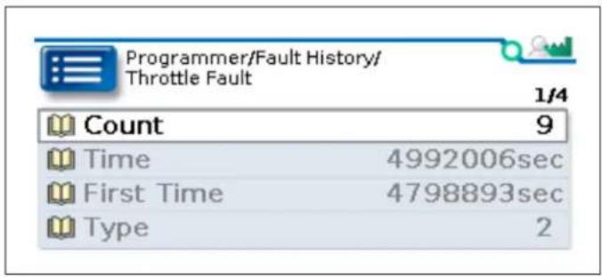
The menu also provides the Clear History parameter:
| PARAMETERCAN INDEX | VALUESRAW VALUES | DATA SIZEREAD/WRITE DESCRIPTION | |
| Clear History0x20F0:01 | Off/On0-1 | 16-bitRW | To clear the fault history, specify On.After the fault history has been cleared, the value reverts to Off. |
7 — FAULTS, DIAGNOSTICS, AND TROUBLESHOOTING
The controller provides diagnostic information to help technicians troubleshoot. You can view the diagnostic information using Curtis programming devices and the controller's status LED.
PROGRAMMING DEVICE DIAGNOSTICS
The following list describes how Curtis programming devices display diagnostic information:
• Real-time data such as the statuses of inputs and outputs are displayed in the Monitor menu.
• A history of faults is displayed in the Fault History menu.
• Active faults are displayed above the parameter menus. The following examples from CIT and the Curtis 1313 Handheld Programmer show that Hardware and Supervision faults are active:
Figure 7-1
Active
Faults — CIT

Figure 7-2
Active Faults —
1313 Handheld
Programmer

Tip: To see a fault's fault type in CIT, expand the fault. To see a fault's fault type in the 1313 Handheld Programmer, select the fault.
STATUS LED
The controller has a red LED that indicates the controller's status. When the controller is operating correctly, the LED flashes once per second.
If the controller detects a fault, the LED continuously flashes a two-digit fault code until the fault is corrected, with a delay following each flash sequence. If more than one fault is active, the LED continuously flashes the fault codes for all the faults.
For example, the following table shows the flash sequence when faults with fault codes 14 and 43 are active. An empty cell indicates a delay following a flash sequence:
| ● | ●●●● | ●●●● | ●●● | ● | ●●●● | ●●●● | ●●● |
FAULT RECORDS
Each fault is represented by a Fault Record. Fault Records are identified by the CAN indexes listed in Table 7-1. The following table describes the sub-indexes of Fault Records:
Note: The 03h–06h sub-indexes correspond to the fault history parameters shown in Figure 6-1.
| SUB-INDEX | FAULT HISTORYPARAMETER | DESCRIPTION READ / WRITE | VALUESDATA SIZE | |
| 01h N/A | The status of the fault: | 00h = The fault has never occurred.01h = The fault is not active.03h = The fault is active. | RO 0–4294967295 | 32-bit |
| 02h N/A | Reserved. N/A | N/A | ||
| 03h | Count | The number of times the fault has occurred since the fault history was cleared. | RO 0–4294967295 | 32-bit |
| 04h | Time | The time, in seconds, of the fault's most recent occurrence since the fault history was cleared.To calculate the number of seconds, divide the value by 10. | RO 0–4294967295 | 32-bit |
| 05h First Time | The time, in seconds, of the fault's first occurrence since the fault history was cleared.To calculate the number of seconds, divide the value by 10. | RO 0–4294967295 | 32-bit | |
| 06h | Type | The fault's fault type.If multiple instances of the fault have occurred and the instances have different fault types, sub-index 06h contains the most recent instance's fault type. | RO 0–4294967295 | 32-bit |
FAULTS
When the controller detects a fault, the controller operates in a manner that is safe in the presence of that fault. Depending on the severity of the fault, the controller's response can range from reducing current to shutting down the vehicle.
Some faults are set by multiple conditions. The controller uses fault types to distinguish these conditions. All faults have a fault type of 1; faults with multiple causes have additional fault types. Curtis programming devices indicate the fault type.
The emergency messages transmitted when faults occur include the fault type. See Emergency Message Format.
The following table describes the controller's faults.
Table 7-1 Fault Chart
| FLASH CODE NAME CAN INDEX | POSSIBLE CAUSES | FAULT TYPE | SET CONDITION CLEAR CONDITION FAULT ACTIONS | ||
| 11 Severe Undervoltage 0x2120 | Defective controllerDefective battery | 1 The | undervoltage cutback is 0 for 64 ms with the main relay on. | Raise the keyswitch voltage above the brownout voltage. | Shut down throttle |
| 12 Undervoltage Cutback 0x2121 | Low battery 1 The undervoltage cut back | is less than 100% with the main relay on. | Raise the keyswitch voltage above the user undervoltage threshold. | Cut back the current limit | |
| 13 Severe Overvoltage 0x2130 | Incorrect battery voltageDefective main relayDefective controller AD | 1 The | keyswitch voltage is 10V above the allowed maximum voltage. | Cycle the keyswitch.Shut down motorShut down main relayShut down throttleShut down EM brake | |
| 2 The | keyswitch voltage is 4V above the allowed maximum voltage. | ||||
| 14 Overvoltage Cutback 0x2131 | Incorrect battery voltageDefective main relay | 1 The | keyswitch voltage is greater than the user overvoltage threshold for 64 ms during the regen state or when the motor speed is greater than 2V. | Lower the keyswitch voltage until it is under the user overvoltage threshold. | Cut back the current limit |
| 15 Controller Severe Undertemp 0x2141 | Defective temperature sensorLow ambient temperature | 1 The | controller temperature is less than or equal to -40°C for 48 ms. | Raise the controller temperature above -40°C. | Shut down throttle |
| 16 Controller Overtemp Cutback 0x2140 | Defective temperature sensorHigh current for an extended period | 1 The | controller temperature is greater than or equal to the temperature cutback point for 48 ms. | Lower the controller temperature to under the temperature cutback point. | Cut back the current limit |
| 17 Controller Severe Overtemp 0x2142 | Defective temperature sensor 1 The controller | temperature is at least 15°C higher than the temperature cutback point for 48 ms. | Lower the controller temperature to under the temperature cutback point. | Shut down throttle | |
Table 7-1 Fault Chart, cont'd
| FLASH CODE NAME CAN INDEX | POSSIBLE CAUSES | FAULT TYPE | SET CONDITION CLEAR CONDITION FAULT ACTIONS | |
| 21 Throttle Fault 0x2210 | Throttle wiring faultIncorrect throttle type settingIncorrect throttle operationSteering angle pot wiring fault | 1 The | throttle AD data is out of range for 48 ms. | Cycle the keyswitch.Shut down throttle |
| 2 The | HPD Sequencing fault is active for 10s. | |||
| 3 The | steering angle AD data is out of range for 48 ms. | |||
| 4 The | throttle calibration process failed. | |||
| 22 HPD Sequencing 0x2211 | Incorrect throttle operationDefective throttle | 1 At least 10% throttle is applied for 48 ms before the interlock state changes to on. | Release the throttle before 10s expires. If the HPD Sequencing fault is active for more than 10s, the Throttle Fault is generated. | |
| 23 Main Relay Welded 0x2220 | Defective main relay 1 The Capacitor Voltage | is greater than (Keyswitch Voltage - 0.7V), and the capacitor bank voltage drop is less than 1.5V after theMain Welded PWMis applied to the motor for 96 ms. | Cycle the keyswitch.Shut down motorShut down main relayShut down throttleShut down interlock | |
| 24 Main Relay Did Not Close 0x2221 | Defective main relayIncorrect Pull In Voltage | 1 The | difference between the keyswitch voltage and capacitor voltage is greater than theDNC Voltage Thresholdfor 96 ms when the relay is engaged. | Cycle the keyswitch.Shut down motorShut down main relayShut down throttleShut down interlock |
| 2 The | difference between the keyswitch voltage and capacitor voltage is greater than the DNC Voltage Threshold for 96 ms after the relay is on. | |||
| 25 BMS Fault 0x2222 | RPDO2 indicates a fault in the BMS. | 1 Byte | 6, bits 1-3, of RPDO2 indicates that the BMS has an active fault. | Clear the battery management system's fault. |
| 2 Shut down lift | ||||
| 3 Cut back speed | ||||
| 4 Shut down throttle | ||||
| 26 Precharge Failed 0x2223 | The PTC resistor in the precharge circuit is defective. | 1 The | Capacitor Voltage is less than 65% of the Keyswitch Voltage for 500 ms after the Keyswitch Voltage is greater than 60% of the nominal voltage at startup. | Cycle the keyswitch.Shut down motorShut down main relayShut down throttleShut down interlock |
| 2 The | Capacitor Voltage is less than (Keyswitch Voltage - 4V) before the relay is engaged. | |||
Table 7-1 Fault Chart, cont'd
| FLASH CODE NAME CAN INDEX | POSSIBLE CAUSES | FAULT TYPE | SET CONDITION CLEAR CONDITION FAULT ACTIONS | |
| 31 Stall Detected 0x2231 | Defective motorDefective controller | 1 The | armature current is greater than 90% of the current limit and the motor speed is less than 10% of the maximum speed for the Stall Fault Time. | Cycle the keyswitch.Shut down motorShut down main relayShut down throttleShut down interlock |
| 32 Motor Fault 0x2240 | The motor is open or shorted. 1 The capacitor | voltage drop is greater than 1V after 10% PWM was applied to the motor for 500 μs at startup. | Cycle the keyswitch.Shut down motorShut down main relayShut down EM brakeShut down throttleShut down interlockOpen armature | |
| 2 The motor is shorted. | ||||
| 3 The motor was open when the system was powered on. | ||||
| 4 The voltage on motor phase M1 is less than 3.5V after the main relay has been engaged. | ||||
| 33 Battery Disconnect Fault 0x2320 | The battery is not connected. 1 The battery is disconnected. Make sure the battery is connected and charged, then cycle the keyswitch. | Shut down motorShut down main relayShut down EM brakeShut down throttleShut down interlockOpen armature | ||
| 34 EM Brake Failed To Set 0x2321 | Defective EM brake 1 The motor speed is | greater than the Fault Motor Revs parameter for 80 ms when the EM brake is engaged. | The throttle is applied.No action | |
| 42 Interlock SRO Fault 0x2532 | Incorrect operation sequenceDefective controller | 1 The | interlock input is on when the keyswitch is turned on and the Interlock Type parameter is not set to KSI Interlock. | Cycle the keyswitch.Shut down motorShut down main relayShut down throttleShut down interlock |
| 43 Low BDI 0x2630 | Low battery 1 The BDI percentage is less | than the Low BDI Threshold parameter value. | Charge the battery until the BDI percentage is greater than Low BDI Threshold. | |
| 44 Speed Supervision 0x2533 | The speed is outside of the allowed range. | 1 The | motor speed is greater than 120% of the allowed maximum speed for more than 500 ms. | Cycle the keyswitch.Shut down throttleShut down interlock |
| 2 The | motor speed is greater than the ramped speed curve for more than 80 ms while the vehicle is decelerating. | |||
| 3 The | motor speed is greater than the ramped speed curve for more than 80 ms during interlock braking. | |||
Table 7-1 Fault Chart, cont'd
| FLASH CODE NAME CAN INDEX | POSSIBLE CAUSES | FAULT TYPE | SET CONDITION CLEAR CONDITION FAULT ACTIONS | |
| 4 The | motor speed is greater than the ramped speed curve for more than 80 ms while the vehicle is decelerating during emergency reverse. | |||
| 5 The | motor speed is greater than the following for more than 2s:Ramped throttle command percentage* maximum speed+ 20% of maximum speed | |||
| 45 Lift Timeout 0x2542 | The lift operating time expired but the lift is still active. | 1 The | lift operating time exceeds the time specified with the Lift Time Limit parameter when the following parameter values are specified:Lift Timeout Enable specifies 1 (On)Lift Time Limit is set to a non-zero value. | Turn off the lift input.Shut down lift. |
| 51 Over Current Fault 0x2241 | Defective controllerDefective current sensor | 1 The | armature current is greater than 120% of the current limit for 160 ms. | Cycle the keyswitch.Shut down motorShut down main relayShut down EM brakeShut down throttleShut down interlockOpen armature |
| 52 Current Sense Fault 0x2250 | Defective current sampling circuit 1 | The zero | current point is out of range for 160 ms (the range is 812 ± 32 ). | Cycle the keyswitch.Shut down motorShut down main relayShut down throttleShut down interlock |
| 2 The | AD data for the current is out of the allowed range. | |||
| 53 Driver Fault 0x2410 | Driver is open or shorted 1 EM Brake driver is | openor shorted. | Cycle the keyswitch.Shut down main relayShut down EM brakeShut down throttle | |
| 2 • The | the lift coil is open when lift driver is off• The lift coil is shorted or driver is open when lift driver is on. | shut down lift | ||
| 3 • The | lower coil is open when lower driver is off.• The lower coil is shorted or driver is open when lower driver is on. | Shut down liftShut down lower | ||
| 4 Horn | driver is shorted.Shut down horn | |||
| 5 The | lift driver is shorted when lift driver is off. | Shut down liftShut down throttleShut down interlockShut down coil supply | ||
Table 7-1 Fault Chart, cont'd
| FLASH CODE NAME CAN INDEX | POSSIBLE CAUSES | FAULT TYPE | SET CONDITION CLEAR CONDITION FAULT ACTIONS | |
| 6 The lower driver is shorted when lower driver is off. | Shut down liftShut down lowerShut down throttleShut down interlockShut down coil supply | |||
| 7 Main relay feedback is high when the relay is on for 100 ms. | Shut down motorShut down main relayShut down throttleShut down interlock | |||
| 8 Main relay feedback is low when the relay is off for 100 ms. | Shut down motorShut down main relayShut down throttleShut down interlock | |||
| 54 Pump SRO Fault 0x2330 | Incorrect operation sequenceDefective switch | 1 The lift input is active when the keyswitch is turned on. | Cycle the keyswitch.Shut down lift | |
| 2 The lower input is active when the keyswitch is turned on. | Cycle the keyswitch.Shut down lift and lower | |||
| 3 The controller did not receive CAN lift or CAN lower PDO messages within 2s after startup. | The Lift Input State and Lower Input State must both be off. | Shut down lift and lower | ||
| 4 The Lift On Interlock parameter specifies On and the lift input is active when the interlock state changes to on. | The Lift Input State and Lower Input State must both be off. | Shut down lift | ||
| 5 The Lower On Interlock parameter specifies On and the lower input is active when the interlock state changes to on. | The Lift Input State and Lower Input State must both be off. | Shut down lift and lower | ||
| 55 EMR SRO Fault 0x2340 | Defective emergency reverse switchIncorrect operation sequence | 1 The emergency reverse switch is active when the keyswitch is turned on. | Cycle the keyswitch.Shut down throttle | |
| 2 The emergency reverse switch is active when the interlock input is turned on and the EMR SRO Type parameter specifies a value other than SRO Off. | Turn off the emergency reverse switch. | |||
| 3 The absolute value of the throttle demand is greater than 10% after an emergency reverse operation and the EMR SRO Type parameter specifies a value other than SRO Off. | Release the throttle. | |||
| 4 Emergency reverse is active when throttle in the forward direction is applied and the EMR SRO Type parameter specifies SRO on Interlock and Throttle. | Cycle the keyswitch. | |||
Table 7-1 Fault Chart, cont'd
| FLASH CODE NAME CAN INDEX | POSSIBLE CAUSES | FAULT TYPE | SET CONDITION CLEAR CONDITION FAULT ACTIONS | ||
| 56 Creep SRO Fault 0x2350 | Incorrect operation sequence 1 The creep input is on when the keyswitch is turned on. | Turn off the creep input.Shut down throttle | |||
| 2 The creep input is on but the interlock state has been off for 40 ms. | Turn off the creep input. | ||||
| 3 The interlock state is on for 40 ms during creep mode. | Turn off creep mode and the interlock. | ||||
| 4 The controller cannot abort the creep brake state after the Interlock Brake Timeout expires. | Turn off creep mode and the interlock. | ||||
| 57 Inching SRO Fault 0x2351 | Incorrect operation sequence 1 The inching forward or inching reverse input is on when the keyswitch is turned on. | Turn off the inching forward and inching reverse inputs. | Shut down throttle | ||
| 2 The inching forward or inching reverse input is on but the interlock state has been off for 40 ms. | Turn off the inching forward and inching reverse inputs. | ||||
| 3 The interlock state is on for 40 ms during inching mode. | Turn off the inching forward, inching reverse and interlock inputs. | ||||
| 4 The inching and throttle inputs are active when the Interlock Type parameter specifies KSI Interlock. | Turn off the inching forward and inching reverse inputs. | ||||
| 61 PDO Timeout 0x2541 | CANbus is overloaded. 1 During the operational NMT state, RPDO1 did not receive a message before the RPDO1 Event Time expired. | Cycle the keyswitch or send an NMT reset command. | Shut down throttle Clear related data | ||
| 2 During the operational NMT state, RPDO2 did not receive a message before the RPDO2 Event Time expired. | |||||
| 5 During the operational NMT state, RPDO2 did not receive a message from the node specified with BMS Node ID before the BMS PDO Timeout expired. | |||||
| 6 During the operational NMT state, a message was not received from the 3150R gauge before the interval specified by the Gauge Setting menu's Timeout parameter expired. | |||||
Table 7-1 Fault Chart, cont'd
| FLASH CODE NAME CAN INDEX | POSSIBLE CAUSES | FAULT TYPE | SET CONDITION CLEAR CONDITION FAULT ACTIONS | |
| 71Hardware Fault0x2610 | Defective MOSFETDefective microprocessor | 1 The | motor voltage is out of range for 64 ms. | Cycle the keyswitch.Shut down motorShut down main relayShut down EM brakeShut down throttleShut down interlockShut down coil supply |
| 3 The | belly button check is enabled and the emergency reverse NO or NC input's voltage is less than 1.5V for 100 ms. | |||
| 4 UID | encryption failed or the microprocessors are not in productive mode. | |||
| 5 The | CAN programming device's OEM code differs from the hardware's OEM code. | |||
| 6 Handshake with the Curtis 3150R gauge failed. | ||||
| 72Software Fault0x2620 | Internal communication failedIncorrect firmware | 1 Unmatched supervisor firmware. | Cycle the keyswitch.Shut down motorShut down main relayShut down EM brakeShut down throttleShut down interlockShut down coil supply | |
| 2 Test | mode was exited. | |||
| Received an NMT Node Reset command while the vehicle was operating. | 3 The | Node Reset command is received when the motor speed is greater than 1.00V or the armature current is greater than (1/16 * Drive Current Limit). | ||
| CAN communication failed. 4 Handshake with the tiller head failed. | ||||
| 81ParameterOut Of Range0x2811 | Invalid parameter value CAN | index of parameter | A parameter's value is outside of its allowed data range. | Cycle the keyswitch.Shut down motorShut down main relayShut down throttleShut down interlockShut down coil supply |
Table 7-1 Fault Chart, cont'd
| FLASH CODE NAME CAN INDEX | POSSIBLE CAUSES | FAULT TYPE | SET CONDITION CLEAR CONDITION FAULT ACTIONS | |
| 82 Parameter Fault 0x2812 | ·Invalid parameter value·Defective FRAM | 1 A parameter marked as [PCF] in the Programming Menu Parameters chapter was set but the keyswitch has not been cycled. | Cycle the keyswitch.Shut down motorShut down main relayShut down throttleShut down interlockShut down coil supply | |
| 2 The Steering Input Type parameter specifies an analog input but the Throttle Type parameter does not specify a CAN throttle. | Cycle the keyswitch. | |||
| 3 Two or more flexible switch inputs are assigned to the same function. | Reconfigure the flexible switch inputs, then cycle the keyswitch. | |||
| 4 ·The Steering Angle 1 parameter is greater than or equal to Steering Angle 2.The Steering Angle 1 or Steering Angle 2 parameter is greater than Steering Angle Max.The speed mode's Fwd Max Speed parameter is less than or equal to Fwd Min Speed.The speed mode's Rev Max Speed parameter is less than or equal to Rev Min Speed.Speed Limit HPD specifies On, and mode 1's Fwd Max Speed is greater than mode 2's Fwd Max Speed, and mode 1's Rev Max Speed is less than mode 2's Rev Max Speed, or vice versa.The Forward Deadband parameter is greater than Forward Max.The Reverse Deadband parameter is greater than Reverse Max. | Adjust the parameter, then cycle the keyswitch. | |||
| 5 ·The EMR Input Type parameter specifies NC Switch Input but the emergency reverse NC function is not assigned to a flexible switch input.The Steering Input Type parameter specifies NC Switch Input but the steering function is not assigned to a flexible switch input. | Assign the function to a flexible switch input, then cycle the keyswitch. | |||
Table 7-1 Fault Chart, cont'd
| FLASH CODE NAME CAN INDEX | POSSIBLE CAUSES | FAULT TYPE | SET CONDITION CLEAR CONDITION FAULT ACTIONS | |
| 6 The | Pot Hi Switch Function parameter specifies a value other than Pot Hi Input but the Throttle Type parameter specifies a 3-wire pot throttle. | Cycle the keyswitch. | ||
| An SDO abort code | Incorrect data size specified for an objectIncorrect access modeInvalid CAN index | Cycle the keyswitch. | ||
| 83 NV Failure0x2830 | FRAM operation failed Block | num-ber | Read FRAM failed. Cycle the keyswitch. Shut down motor | |
| 2 Write FRAM failed. | ||||
| 3 Restore parameters failed during flashing. | ||||
| 4 Saving the brownout flag failed. | ||||
| 5 Block number is out of range. | ||||
| 84 Supervision0x2840 | Cross check failed. See | Table7-2 | Cross check failed Cycle the keyswitch. Shut down motor | |
The following table lists the fault types for the Supervision fault.
Table 7-2 Supervisor Fault Types
| Fault Type Fault Type Variable |
| 2 SUPERVISOR_FIFTEEN_V_SUPPLY_FAILURE |
| 8 SUPERVISOR_HARDWARE_FAULT |
| 11 PRIMARY_INIT_CAN_OBJ |
| 12 PRIMARY_INIT_ILLEGAL_CAN_SIZE |
| 13 PRIMARY_INIT_CAN_SIZE |
| 14 PRIMARY_INIT_TIMEOUT |
| 15 PRIMARY_WRITE_OBJECT |
| 16 PRIMARY_WRITE_SIZE |
| 17 PRIMARY_WRITE_TIMEOUT |
| 18 PRIMARY_WRITE_CRC |
Table 7-2 Supervisor Fault Types, cont'd
| Fault Type Fault Type Variable |
| 19 PRIMARY_WRITE_ACK |
| 20 PRIMARY_TASK_QUEUE_FAIL |
| 21 PRIMARY_FAULT_ACTIONS |
| 22 PRIMARY_ALU_FAIL |
| 23 PRIMARY_MESSAGE_WATCHDOG |
| 24 PRIMARY_FAULT_ACK |
| 25 SUPERVISOR_INIT_CAN_OBJ |
| 26 SUPERVISOR_INIT_ILLEGAL_CAN_SIZE |
| 27 SUPERVISOR_INIT_CAN_SIZE |
| 28 SUPERVISOR_INIT_TIMEOUT |
| 29 SUPERVISOR_WRITE_OBJECT |
| 30 SUPERVISOR_WRITE_SIZE |
| 31 SUPERVISOR_TASK_QUEUE_FAIL |
| 32 SUPERVISOR_ALU_FAIL |
| 33 SUPERVISOR_MESSAGE_WATCHDOG |
| 34 SUPERVISOR_KSI |
| 35 SUPERVISOR_INPUT_1_SWITCH |
| 36 SUPERVISOR_INPUT_2_SWITCH |
| 37 SUPERVISOR_INPUT_3_SWITCH |
| 38 SUPERVISOR_INPUT_4_SWITCH |
| 39 SUPERVISOR_INPUT_5_SWITCH |
| 43 PRIMARY_INPUT_1_SWITCH |
| 44 PRIMARY_INPUT_2_SWITCH |
| 45 PRIMARY_INPUT_3_SWITCH |
| 46 PRIMARY_INPUT_4_SWITCH |
| 47 PRIMARY_INPUT_5_SWITCH |
8 — CANopen COMMUNICATIONS
The controller is fully CANopen compliant per CiA 301. This chapter describes the controller's CANopen features.
Some familiarity with CANopen is a prerequisite. For CANopen information, see the following pages on the CiA web site:
• Overview: https://www.can-cia.org/canopen/
- Specifications: https://www.can-cia.org/groups/specifications/
BYTE AND BIT SEQUENCE ORDER
CANopen message byte sequences are transmitted with the least significant byte first (Little-Endian format).
Note: This manual uses the LSB 0 Numbering convention when referring to byte and bit numbers.
For example, the following table shows an SDO that writes the data 04E2h to the object with the index and sub-index 334C-01h:
| 01234567 | |||||||
| Control Byte Index Sub-index Data | |||||||
| 2Bh | 4Ch | 33h | 01h | E2h | 04h | 00h | 00h |
Strings are read from left to right. The following example shows how the controller transmits an SDO segment for the string "1212E":
| 01234567 | |||||||
| Control Byte | Data | ||||||
| 00h | 31h = "1" | 32h = "2" | 31h = "1" | 32h = "2" | 45h = "E" | ||
Bit sequences are transmitted from most significant to least significant bit (Big-Endian format). The following example shows how the controller transmits the bits for the value 2Bh:
| 76543210 | ||||||
| 00101011 |
CAN PROGRAMMING CONSIDERATIONS
The following considerations apply when programming the controller:
- When a Curtis programming device is connected, the programmer uses 127 as the node ID.
- When you change parameter values with a Curtis programming device, you do not need to use the CANopen Store Parameters object (1010h). Instead, the controller saves parameter changes to NVM.
NODE IDs
The controller provides an option for two node IDs, which are configured by the CAN Node ID 1 and CAN Node ID 2 parameters on the CAN Interface menu. The CAN Node ID 1 parameter indicates the controller's primary node ID.
Some applications, such as dual traction applications, require two CAN nodes. For such applications, connect a switch to switch input 4 and set the Switch 4 Function parameter to Flex ID. This configuration enables applications to use either the CAN Node ID 1 or CAN Node ID 2 parameter value as the node ID, depending upon the state of switch input 4. When switch input 4 is active at start up, CAN Node ID 2 is used, otherwise CAN Node ID 1 is used.
MESSAGE CAN-IDs
The controller's CAN messages are identified by 11-bit CAN IDs. The controller does not use 29-bit CAN IDs.
NMT STATE CONFIGURATION
The Auto Operational parameter indicates whether the controller enters the operational or pre-operational state when the controller is powered up.
NMT, emergency, SDO, and heartbeat messages are available in both states. PDO messages are transmitted and received only in the operational state.
EMERGENCY MESSAGES AND FAULTS
The controller transmits an emergency message when a fault is generated or cleared. An emergency message is sent once per fault.
Emergency Message Format
Emergency messages consist of 8 bytes, which are described in the following table:
| Byte(s) Name Description | ||
| 0-1 | Error Code | Indicates the fault code and the error category:Byte 0 indicates the fault code, which is in the following format:The four most significant bits contain the fault code's first digit.The four least significant bits contain the fault code's second digit.For example, if the fault code is 82, the byte's value would be 82h.Note: Fault codes are listed in Table 7-1.Byte 1 indicates one of the following error categories:FFh = Active fault00h = Cleared fault |
| 2 Error Register Indicates whether any faults are active on the transmitting device:00h = No active faults01h = At least one active faultThe value equals the value of the least significant bit in the Error Register object. | ||
| 3-4 | Fault Record Object Index | Indicates the CAN index of the Fault Record. |
| 5 | Fault Type | Indicates the fault's fault type. |
| 6-7 | Descriptor | Provides additional information about the fault. These bytes are often used to indicate the fault's cause. |
The following emergency message indicates that a fault with fault code 82 is active. The fault's CAN index is 2812h and the fault type is 1:
82 FF 01 12 28 01 00 00
EXPEDITED SDOs
The least significant byte of an expedited SDO is known as the control byte. The following table describes the control byte fields:
| 76543210 | ||||||
| Command Specifier 0b n e s | ||||||
The following list describes the control byte:
- The Command Specifier field indicates the SDO's transfer type:
| Transfer Type Value | |
| Write data to a device 001b | |
| Confirm a write | 011b |
| Request data from a device | 010b |
| Device responds with requested data | 010b |
| Abort SDO | 100b |
- Bit 4 is always 0b.
-
The values of bits 0–3 depend upon whether the SDO transfers data. If the SDO does not transfer data, these bits are always 0b. If the SDO transfers data, the bit values are as follows:
-
n indicates the number of unused data bytes.
- e = 1b , which indicates the message contains data.
- s = 1b , which indicates that the n field specifies the number of unused data bytes.
The following table lists the control byte values for the various transfer types:
| Transfer Type | Control Byte |
| Write data to a device | Depends upon the data size:1 byte = 2Fh2 bytes = 2Bh3 bytes = 27h4 bytes = 23h |
| Confirm a write | 60h |
| Request data from a device | 40h |
| Device responds with requested data | Depends upon the data size:1 byte = 4Fh2 bytes = 4Bh3 bytes = 47h4 bytes = 43h |
| Abort SDO | 80h |
PDOs
The controller provides two preconfigured RPDOs and two preconfigured TPDOs:
- RPDO1, TPDO1, and TPDO2 are preconfigured to communicate with a CAN tiller head.
- RPDO2 is preconfigured to receive data transmitted by a battery monitoring system (BMS).
If the application does not require these preconfigured functions, the PDOs can be mapped to other CAN objects. The following topics describe the controller's PDOs.
PDO Timing
The controller's PDOs are asynchronous and are periodically transmitted and received. The controller does not support synchronous PDOs.
A PDO's Event Time parameter indicates when the PDO transmits or expects to receive data:
- A TPDO transmits periodically using the specified time interval. A TPDO also transmits data when the value of a mapped object changes.
- A PDO Timeout fault occurs if an RPDO does not receive data before its Event Time expires.
PDO Mapping Objects
The objects for which a PDO transfers data are specified with the sub-indexes of the PDO's mapping object. Each sub-index specifies a CAN object's index, sub-index, and data length.
The following table describes the mapping objects' sub-indexes:
| Sub-Index Description PDO Mapping Menu Parameter | |
| 00h Indicates the number of objects for which the PDO transfers data. | Length |
| 01h–08h Each sub-index specifies a CAN object that is mapped to the PDO. The bytes specify the CAN object's index, sub-index, and length. | Map 1 through Map 8 |
The mapped objects consist of four data bytes, which are described in the following table:
Table 8-1 Mapped PDO Bytes
| Byte(s) Description | |
| 0 The size of the object's data, in bits. The allowed values are:08h (8 bits)10h (16 bits)18h (24 bits)20h (32 bits)The controller does not support mapping of individual bits. | |
| 1 The object's sub-index. | |
| 2–3 The object's index. |
PDO Data Bytes
A PDO transfers a maximum of 8 data bytes. The order of the bytes corresponds to the order of the PDO's mapped objects.
For example, consider the following PDO map, which contains two 8-bit objects:
| Name | Device Value | ||
| TPDO 2 Event Time | 40 ms | ||
| TPDO 2 COB ID | 400002ACh | ||
| Length | 2 | ||
| Map 1 | 4E020008h | ||
| Map 2 | 4E050008h | ||
| Map 3 | 50008h |
Suppose the PDO transmits the following data:
82h 04h
The least significant byte transfers the data (82h) for the object specified with the Map 1 parameter, and the next byte transfers the data for the second mapped object.
Map CAN Objects to a PDO
Take the following steps to use a Curtis programming device to map CAN objects to a PDO.
Note: The screen shots are from CIT.
- Send an NMT message that changes the device to the Pre-operational state.
- Disable the PDO by changing the COB-ID's most significant bit to 1.
- Change the Length parameter to 0.
The following example shows the disabled PDO:
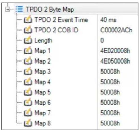
-
For each object to be mapped, specify the object's data in a Map n parameter. The data is described in Table 8-1.
-
Set the Length parameter to the number of mapped objects.
-
Enable the PDO by changing its COB-ID's most significant bit to 0.
The following example shows the enabled PDO, which now contains three mapped objects:
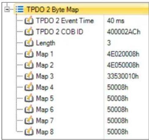
- Send an NMT message that changes the device to the Operational state.
CAN Tiller Head (RPDO1, TPDO1, TPDO2)
RPDO1, TPDO1, and TPDO2 are preconfigured to communicate with a CAN tiller head:
• RPDO1: Receives messages from the tiller head.
- TPDO1: Transmits data for switch statuses, driver states, the hour meter, and the Analog 1 input's voltage.
- TPDO2: Transmits data describing active faults and the Analog 2 input's voltage.
The following tables describe the objects with which these PDOs are preconfigured.
Note: For information on configuring CAN inputs, see I/Os.
Table 8-2 RPDO1 Data
| Byte(s) Description | |
| 0-1 Switch commands from the tiller head. The switches are represented by the following bits, with 0 = inactive and 1 = active:0 = Reverse switch1 = Forward switch2 = Mode switch3 = Belly button switch4 = Lift switch5 = Lower switch6 = Creep mode switch7 = Push switch (Reserved)8 = Interlock switch9 = Horn switch10 = Lift Lockout switch11 = Inhibit switch12 = Inching forward switch13 = Inching reverse switch | |
| 2-3 The throttle request. The CAN Throttle Min and CAN Throttle Max parameters specify the allowed data range. | |
| 4-5 Reserved. | |
| 6-7 The CAN steering angle. The angle can be -90.0° to 90.0° . The CAN data range is -16384 to 16383 . |
Table 8-3 TPDO1 Data
| Byte(s) Description | |
| 0-1 The controller's switch statuses. The switches are represented by the following bits, with 0 = inactive and 1 = active:0 = Charger inhibit switch1 = Emergency reverse NO switch2 = Mode switch3 = Interlock switch4 = Creep mode switch5 = Reverse switch6 = Forward switch7 = Flexible switch input 18 = Flexible switch input 29 = Flexible switch input 310 = Flexible switch input 411 = Flexible switch input 512 = Lift inhibit switch13 = Lift driver state14 = Lower driver state | |
| 2-3 The Analog 1 input's voltage. The voltage ranges from 0-20.00V. The CAN data range is 0-2000. | |
| 4-7 The time that has elapsed since the hour meter was last set to 0.The time ranges from 0.0-999999.9 hours. The CAN data range is 0-9999999. | |
Table 8-4 TPDO2 Data
| Byte(s) Description |
| 0 Indicates the fault code, which is in the following format:The 4 most significant bits indicate the fault code’s first digit.The 4 least significant bits indicate the fault code’s second digit.For example, if the fault code is 82, the byte’s value would be 82h. |
| 1 Indicates the fault type. |
| 2–3 The Analog 2 input’s voltage. The voltage ranges from 0–20.00V. The CAN data range is 0–2000. |
BMS (RPDO2)
RPDO2 is preconfigured to receive messages transmitted by a BMS. The BMS Node ID parameter specifies the BMS's node ID. The timeout interval for receiving BMS messages is specified with the BMS PDO Timeout parameter. If the timeout expires, a PDO Timeout (Type 5) fault occurs.
The following table describes the objects with which RPDO2 is preconfigured.
Table 8-5 RPDO2 Data
| Byte(s) Description | |
| 0–3 Reserved. | |
| 4 The state-of-charge, which ranges from 0–100%. The CAN data range is 0–255. | |
| 5 Bit 0 specifies the charging status. When charging is active, traction, lift and lower functions are inhibited.The other bits are reserved. | |
| 6 Bits that indicate the BMS’s fault action status, with 0 = off and 1 = on:0 = Warning (no action)1 = Lift lockout. When on, the lift is inhibited.2 = Cutback. When on, the maximum speed is reduced to the speed specified by the Low BDI Max Speed parameter and the current limit is reduced by 50%.3 = Cutoff. When this bit is 1, traction, lift, and lower are inhibited.The other bits are reserved.Note: If any of bits 1–3 are on, the controller generates a BMS fault. | |
| 7 The BMS temperature, which ranges from –100°C to 155°C. The CAN data range is 0–255. |
STANDARD CANopen OBJECTS
The following table describes considerations for Curtis's implementation of some of the standard CANopen objects:
Note: The controller supports all CANopen objects required by CiA 301, not just the objects discussed in the following table.
| Name Index Description | ||
| Error Register 1001h Indicates | if a fault is active:0 = No active fault1 = One or more active faults | |
| Error History 1003h See Error History Object (1003h). | ||
| Inhibit Time EMCY | 1015h | This object is represented by the Emergency Message Rate parameter. |
| Producer Heartbeat Time | 1017h | This object is represented by the Heartbeat Rate parameter. |
| Identity Object 1018h Provides | information on the controller. The following list describes the sub-indexes:00h: The size of the object.01h: The CiA-assigned identifier of Curtis Instruments, which is 4349h.02h: The controller's product code.03h: The controller's Curtis CAN protocol version. The upper 2 bytes contain the major version and the lower 2 bytes contain the minor version.04h: The controller's serial number. | |
Error History Object (1003h)
The CANopen Error History object at index 1003h provides data on the four most recently detected faults. The sub-indexes correspond to the order in which the faults occurred. Sub-index 01h records the most recent fault, sub-index 02h records the second most recent fault, etc.
The fault data consists of four bytes, which are described in the following table:
| Byte(s) | Description |
| 0–1 | Contains an error category and the fault code:Byte 0 indicates the fault code, which is in the following format:The 4 most significant bits indicate the fault code’s first digit.The 4 least significant bits indicate the fault code’s second digit.For example, if the fault code is 82, the byte’s value would be 82h.Byte 1 indicates the error category, which will be one of the following:FFh = Active fault00h = All faults are cleared |
| 2–3 | Indicates how many hours after the hour meter was last set to 0 that the fault occurred. |
EM BRAKE OVERRIDE OBJECT
If the EM Brake Type parameter specifies EM Brake Disable, the controller's EM brake function can be controlled by the EM Brake Override object:
| CAN Index | Values Raw Values | Data Size |
| 0x340B:00 | 0-100% 0-255 | 32-bit |
BDI PERCENTAGE OBJECT
If the BDI Source parameter specifies CAN BDI, the BDI data is received by the BDI Percentage object:
| CAN Index | Values Raw Values | Data Size |
| 0x33AF:00 | 0–100%0–100 | 8-bit |
9 — COMMISSIONING
After you have wired and configured the I/Os, use the following topics to configure the throttle, system resistance, minimum and maximum speeds, and acceleration and deceleration rates.
TUNE THE THROTTLE
It is important to tune the throttle so that it operates over the throttle's full range. When you tune the throttle, include a buffer around the absolute full range of the throttle mechanism. This will allow for throttle resistance variations over time and temperature and for variations in the tolerance of potentiometer values between individual throttle mechanisms.
Take the following steps to configure the throttle so that it is compatible with your vehicle's requirements:
Step 1. Prepare the Vehicle
Step 2. Tune the Deadband
Step 3. Tune the Throttle Demand
Step 4. Confirm Throttle Operation
Step 5. Verify the Vehicle's Configuration
To program the parameters to which this chapter refers, use the Curtis Integrated Toolkit or the 1313 Handheld Programmer.
Step 1 Prepare the Vehicle
Take the following steps before tuning the throttle.
CAUTION
It is critical that you perform these steps.
- Jack the vehicle drive wheels up off the ground so that they spin freely.
- Make sure the vehicle is stable.
- Double-check all wiring to ensure that it is consistent with the wiring guidelines. See Installation, Wiring, and I/O Configuration.
- Make sure all connections are tight.
- Put the throttle in neutral.
- Turn off the forward/reverse switches.
- Turn on the controller.
Step 2 Tune the Deadband
Check whether the throttle's deadband range provides a good balance. The deadband should be wide enough for the throttle to return to neutral when released, but also should not allow an excessive amount of travel in the neutral zone.
If the deadband needs tuning, perform the following steps.
- Select Programming » Throttle.
-
Adjust the Forward Deadband as follows:
-
If the throttle travels too far when starting out of neutral before the brake disengages, decrease the Forward Deadband value.
-
If the brake sometimes doesn't engage when the throttle is returned to neutral, increase the Forward Deadband value.
-
If a wigwag throttle assembly is being used, repeat the previous step using the Reverse Deadband parameter; otherwise, set Reverse Deadband to the same value as Forward Deadband.
Step 3 Tune the Throttle Demand
Take the following steps to ensure the controller output is 100% when full throttle is applied:
- Select Monitor » Controller.
-
Apply full throttle and observe the Throttle Demand value. This value should be 100% at full throttle. If the Throttle Demand value is less than 100%, perform the following steps:
2.1. Select Programming » Throttle.
2.2. Decrease the Forward Max value.
2.3. Select Monitor » Controller.
2.4. Apply full throttle and observe the Throttle Demand value.
2.5. If the value is less than 100%, repeat these steps until the value is 100%. -
Slowly reduce the throttle until the Throttle Demand value drops below 100%, then note the throttle position.
The throttle position represents the extra range of motion allowed by the throttle mechanism. You can increase the throttle's active range and provide more vehicle control by taking the following steps.
3.1. Select Programming » Throttle.
3.2. Increase the Forward Max value.
3.3. Select Monitor » Controller.
3.4. Slowly reduce the throttle until the Throttle Demand value drops below 100%, then note the throttle position.
3.5. Repeat this step until you are satisfied with the throttle's active range.
- If a wigwag throttle is being used, repeat these steps using the Reverse Max parameter; otherwise, set Reverse Max to the same value as Forward Max.
Step 4 Confirm Throttle Operation
To confirm the throttle is operating correctly, select a direction and operate the throttle. The motor should rotate in the direction you selected. If it does not, verify the wiring to the throttle and motor. The motor should run proportionally faster with increasing throttle. If not, use the Throttle menu to adjust the throttle parameters.
Step 5 Verify the Vehicle's Configuration
Take the following steps to verify that critical parameters are correctly set.
- Select Monitor » Inputs.
- Cycle each switch and make sure that the switch state changes from on to off.
- Apply the throttle, then verify that the Throttle Demand parameter changes.
- Verify that you've correctly set the functions meeting the vehicle's requirements, such as emergency reverse, HPD, and so on.
- After you have validated the parameter settings, lower the vehicle drive wheels onto the ground.
SET THE SYSTEM RESISTANCE
It is critical to set the System Resistance parameter accurately. To do so, take the following steps.
Note: Perform these steps quickly and with the motor cold. A warm motor will result in incorrect settings. If you need to repeat these steps, allow the motor to completely cool.
- Position the vehicle up against an immovable object such as a wall or high curb.
- Turn on the keyswitch.
- Select Programming » Current » Boost.
- Set Boost Enable to Off.
- Select Programming » Current.
- Set the Drive Current Limit parameter to 35A.
- Select Monitor » Motor.
- Apply full throttle in the forward direction, driving the vehicle against the immovable object.
- Note the Motor Resistance Measured parameter's value.
- Repeat steps 8 and 9 three more times.
- Select Programming » Motor.
- Set the System Resistance parameter to the average of the four Motor Resistance Measured values.
-
Before tuning the vehicle, reset the following parameters to their original values:
-
Drive Current Limit
- Boost Enable
TUNE VEHICLE PERFORMANCE
You can customize many aspects of vehicle performance by configuring the controller's parameters. Once you have tuned a vehicle system, you can make the parameter values standard for that system or vehicle model.
CAUTION
If the system's motor, vehicle drive system, or controller changes, you must retune the system to provide optimum performance.
Take the following steps to tune vehicle performance:
Step 1. Set the Maximum and Minimum Speeds.
Step 2. Set the Acceleration and Deceleration Rates.
It is important to perform these steps in order, because each step builds upon the previous steps.
Step 1 Set the Maximum and Minimum Speeds
For each speed mode, you can configure maximum and minimum speeds for both the forward and reverse directions. Use the following parameters to define the maximum and minimum speeds. For information on these parameters, see Mode 1 and Mode 2 Menus:
- Fwd Max Speed
- Rev Max Speed
- Fwd Min Speed
- Rev Min Speed
Each of these speeds is programmed as a percentage of the motor's maximum speed.
Step 2 Set the Acceleration and Deceleration Rates
The controller's acceleration and deceleration features provide smooth throttle response when maneuvering at low speeds and snappy throttle response when traveling at high speeds. For more information, see Low and High Speed Acceleration Rates.
To configure your vehicle's acceleration and deceleration rates, take the following steps.
- Select Programming » Speed Mode.
- Set the Low Speed parameter to the percentage of motor speed at or below which the controller should apply the low speed acceleration rate.
- Set the High Speed parameter to the percentage of motor speed at or above which the controller should apply the high speed acceleration rate.
- Perform the following steps:
4.1. Select the Mode 1 menu.
4.2. Set the Full Accel Rate LS parameter to the rate at which the vehicle should accelerate when full throttle is applied while the vehicle is traveling at low speed.
4.3. Drive the vehicle at a low speed, then apply full throttle. Adjust Full Accel Rate LS until you are satisfied with the vehicle's low speed acceleration.
For low speed testing, we recommend that you drive in a confined area such as an office where low speed maneuverability is crucial.
4.4. Set the Neutral Decel Rate LS parameter to the rate at which the vehicle should decelerate when the throttle is released to neutral at low speeds.
4.5. Drive the vehicle at a low speed, then release the throttle to neutral. Adjust Neutral Decel Rate LS until you are satisfied with the vehicle's low speed deceleration.
4.6. Set the Full Accel Rate HS parameter to the rate at which the vehicle should accelerate when full throttle is applied at high speeds.
4.7. Drive the vehicle at a high speed, then apply full throttle. Adjust Full Accel Rate HS until you are satisfied with the vehicle's high speed acceleration.
4.8. Set the Neutral Decel Rate HS parameter to the rate at which the vehicle should decelerate when the throttle is released to neutral at high speeds.
4.9. Drive the vehicle at a high speed, then release the throttle to neutral. Adjust Neutral Decel Rate HS until you are satisfied with the vehicle's high speed deceleration.
4.10. Select the Mode 2 menu.
4.11. Repeat steps 4.2 through 4.9.
The following list describes additional functions that might require tuning:
- Use the Forward Map and Reverse Map parameters to adjust the relationship between the throttle input and acceleration rate. By default, the throttle input and acceleration rate have a linear relationship. Some applications require adjusting this relationship. For more information, see Throttle Response Parameters.
- You can extend the throttle's gentle acceleration range to further enhance maneuverability in confined areas. For more information, see Low and High Speed Acceleration Rates.
10 — MAINTENANCE
There are no user-serviceable parts in the controller. Do not attempt to open, repair, or otherwise modify the controller. Doing so may damage the controller and will void the warranty.
It is recommended that the controller's fault history be checked and cleared periodically as part of routine vehicle maintenance.
DIAGNOSTIC HISTORY
You can use a Curtis programming device to access the controller's fault history. The programming device shows the faults that have occurred since the fault history was last cleared. The faults may be intermittent faults, faults caused by loose wires, or faults caused by operator errors. Faults such as HPD or overtemperature may be caused by operator habits or by overloading.
After a problem has been diagnosed and corrected, clearing the fault history is recommended. This allows the controller to accumulate a new fault history.
APPENDIX A — VEHICLE DESIGN CONSIDERATIONS REGARDING ELECTROMAGNETIC COMPATIBILITY (EMC)
Electromagnetic compatibility (EMC) encompasses two areas: emissions and immunity. Emissions are radio frequency (RF) energy generated by a product. This energy has the potential to interfere with communications systems such as radio, television, cellular phones, dispatching, aircraft, etc. Immunity is the ability of a product to operate normally in the presence of RF energy.
EMC is ultimately a system design issue. Part of the EMC performance is designed into or inherent in each component; another part is designed into or inherent in end product characteristics such as shielding, wiring, and layout; and, finally, a portion is a function of the interactions between all these parts. The design techniques presented below can enhance EMC performance in products that use Curtis motor controllers.
EMISSIONS
Signals with high frequency content can produce significant emissions if connected to a large enough radiating area (created by long wires spaced far apart). Contactor drivers and the motor drive output from Curtis controllers can contribute to RF emissions. Both types of output are pulse width modulated square waves with fast rise and fall times that are rich in harmonics. (Note: Contactor drivers that are not modulated will not contribute to emissions.) The impact of these switching waveforms can be minimized by making the wires from the controller to the contactor or motor as short as possible and by placing the wires near each other (bundle contactor wires with Coil Return; bundle motor wires separately).
For applications requiring very low emissions, the solution may involve enclosing the controller, interconnect wires, contactors, and motor together in one shielded box. Emissions can also couple to battery supply leads and throttle circuit wires outside the box, so ferrite beads near the controller may also be required on these unshielded wires in some applications. It is best to keep the noisy signals as far as possible from sensitive wires.
IMMUNITY
Immunity to radiated electric fields can be improved either by reducing overall circuit sensitivity or by keeping undesired signals away from this circuitry. The controller circuitry itself cannot be made less sensitive, since it must accurately detect and process low level signals from sensors such as the throttle potentiometer. Thus immunity is generally achieved by preventing the external RF energy from coupling into sensitive circuitry. This RF energy can get into the controller circuitry via conducted paths and radiated paths.
Conducted paths are created by the wires connected to the controller. These wires act as antennas and the amount of RF energy coupled into them is generally proportional to their length. The RF voltages and currents induced in each wire are applied to the controller pin to which the wire is connected. Curtis controllers include bypass capacitors on the printed circuit board's throttle wires to reduce the impact of this RF energy on the internal circuitry. In some applications, additional filtering in the form of ferrite beads may also be required on various wires to achieve desired performance levels.
Radiated paths are created when the controller circuitry is immersed in an external field. This coupling can be reduced by placing the controller as far as possible from the noise source or by enclosing the controller in a metal box. Some Curtis controllers are enclosed by a heatsink that also provides shielding around the controller circuitry, while others are partially shielded or unshielded. In some applications, the vehicle designer will need to mount the controller within a shielded box on the end product. The box can be constructed of just about any metal, although steel and aluminum are most commonly used.
Most coated plastics do not provide good shielding because the coatings are not true metals, but rather a mixture of small metal particles in a non-conductive binder. These relatively isolated particles may appear to be good based on a DC resistance measurement but do not provide adequate electron mobility to yield good shielding effectiveness. Electroless plating of plastic will yield a true metal and can thus be effective as an RF shield, but it is usually more expensive than the coatings.
A contiguous metal enclosure without any holes or seams, known as a Faraday cage, provides the best shielding for the given material and frequency. When a hole or holes are added, RF currents flowing on the outside surface of the shield must take a longer path to get around the hole than if the surface was contiguous. As more “bending” is required of these currents, more energy is coupled to the inside surface, and thus the shielding effectiveness is reduced. The reduction in shielding is a function of the longest linear dimension of a hole rather than the area. This concept is often applied where ventilation is necessary, in which case many small holes are preferable to a few larger ones.
Applying this same concept to seams or joints between adjacent pieces or segments of a shielded enclosure, it is important to minimize the open length of these seams. Seam length is the distance between points where good ohmic contact is made. This contact can be provided by solder, welds, or pressure contact. If pressure contact is used, attention must be paid to the corrosion characteristics of the shield material and any corrosion-resistant processes applied to the base material. If the ohmic contact itself is not continuous, the shielding effectiveness can be maximized by making the joints between adjacent pieces overlapping rather than abutted.
The shielding effectiveness of an enclosure is further reduced when a wire passes through a hole in the enclosure; RF energy on the wire from an external field is re-radiated into the interior of the enclosure. This coupling mechanism can be reduced by filtering the wire where it passes through the shield boundary. Given the safety considerations involved in connecting electrical components to the chassis or frame in battery powered vehicles, such filtering will usually consist of a series inductor (or ferrite bead) rather than a shunt capacitor. If a capacitor is used, it must have a voltage rating and leakage characteristics that will allow the end product to meet applicable safety regulations.
The B+ (and B−, if applicable) wires that supply power to a control panel should be bundled with the other control wires to the panel so that all these wires are routed together. If the wires to the control panel are routed separately, a larger loop area is formed. Larger loop areas produce more efficient antennas which will result in decreased immunity performance.
Keep all low power I/O separate from the motor and battery leads. When this is not possible, cross them at right angles.
APPENDIX B — EN 13849 COMPLIANCE
Since January 1, 2012, conformance to the European Machinery Directive has required that the Safety Related Parts of the Control System (SRPCS) be designed and verified upon the general principles outlined in EN 13849. EN 13849 supersedes the EN 954 standard and expands upon it by requiring the determination of the safety Performance Level (PL) as a function of Designated Architecture plus Mean Time To Dangerous Failure (MTTF d ), Common Cause Faults (CCF), and Diagnostic Coverage (DC). These figures are used by the OEM to calculate the overall PL for each of the safety functions of their vehicle or machine.
The OEM must determine the hazards that are applicable to their vehicle design, operation, and environment. Standards such as EN 13849-1 provide guidelines that must be followed in order to achieve compliance. Some industries have developed further standards (called Type-C standards) that refer to EN 13849 and specifically outline the path to regulatory compliance. EN 1175 is a Type-C standard for battery-powered industrial trucks. Following a Type-C standard provides a presumption of conformity to the Machinery Directive.
Curtis controllers comply with these directives using advanced active supervisory techniques.
The controller is designed to the requirements of EN 13849-1:2015. To mitigate the hazards typically found in machine operations, EN 13849-1:2015 requires that safety functions be defined; these must include all the input, logic, outputs, and power circuits that are involved in any potentially hazardous operation.
Curtis has analyzed each safety function and calculated its Mean Time To Dangerous Failure (MTTE) and Diagnostic Coverage (DC), and designed them against Common Cause Faults (CCF). The safety-related performance of the controller is summarized in the following table:
Table B-1 Safety Functions
| Safety Function PL Category | Diagnostic Coverage | MTTFd (years) | CCF | ||
| Traction Motor Speed Limitation c 2 >60.0% >100 Pass | |||||
| Deviation from setpoint (LHS) — DC Pump | c 2 >60.0% >100 Pass | ||||
| E-Stop Direct Disconnect c 1 0.0% >100 Pass | |||||
| EM Brake Control c 2 >60.0% >100 Pass | |||||
| Emergency Reverse c 2 >60.0% >100 Pass | |||||
| Hazardous Movement — From Rest | c 2 >60.0% >100 Pass | ||||
| Hazardous Movement — While Moving | c 2 >60.0% >100 Pass | ||||
| Hydraulic HPD/SRO | c 2 >60.0% >100 Pass | ||||
| Interlock Braking | c 2 >60.0% >100 Pass | ||||
| Throttle HPD/SRO | c 2 >60.0% >100 Pass | ||||
| Battery Charging | c 2 >60.0% >100 Pass | ||||
| Automatic Restoration of Drive System Protection | c 2 >60.0% >100 Pass | ||||
EN 1175 specifies that traction and hydraulic electronic control systems must use Designated Architecture 2 or greater. This design employs input, logic, and output circuits that are monitored and tested by independent circuits and software to ensure a high level of safety performance (up to PL=c).
Mean Time To Dangerous Failure (MTTF d ) is related to the expected reliability of the safety related parts used in the controller. Only failures that can result in a dangerous situation are included in the calculation.
Diagnostic Coverage (DC) is a measure of the effectiveness of the control system's self-test and monitoring measures to detect failures and provide a safe shutdown.
Common Cause Faults (CCF) are so named because some faults within a controller can affect several systems. EN 13849-1:2015 provides a checklist of design techniques that should be followed to achieve sufficient mitigation of CCFs. All circuits used by a safety function must be designed in such a way as to score 65 or better on the CCF score sheet as provided by EN 13849-1:2015, table F.1.
Performance Level (PL) categorizes the quality or effectiveness of a safety channel to reduce the potential risk caused by dangerous faults within the system with “a” being the lowest and “e” being the highest achievable performance.
Contact Curtis technical support for more details.
APPENDIX C — CURTIS PROGRAMMING DEVICES
Curtis programming devices provide programming, diagnostic, and test capabilities for Curtis CAN devices. Two programming devices are available for the controller:
• 1313 Handheld Programmer
• Curtis Integrated Toolkit™ (CIT)
CIT has the advantage of a large, easy-to-read screen. On the other hand, the 1313 Handheld Programmer is more portable, which makes it convenient for working in the field.
The programming devices include the following features:
- Parameter adjustment. Save and restore the values of programmable parameters.
- Monitoring: Display real-time values during vehicle operation. These values include data for inputs and outputs.
- Diagnostics and troubleshooting: Display active faults and the fault history, and allow users to clear the fault history.
- Flashing: Update firmware of Curtis devices.
The programmers are available for the following access levels. The bullets are sorted from the highest to lowest access level:
- OEM Factory
- OEM Dealer
- Field Advanced
• Field Intermediate - Field Basic
A Curtis programmer can perform the actions available at or below its access level. For example, a Field Basic programmer can only perform actions available for the Field Basic access level, while an OEM Factory programmer can perform all actions available for any of these access levels.
The following example shows the Current menu in the CIT Programmer application. You can view or edit a parameter by selecting it on the left-hand side. You can also view and edit all of a menu's parameters in one window by selecting the menu as shown below:
| Name | Device_ | Name | Device Value | Project Value | Min Value | Max Value | |||||
| Main Relay | Pull In Voltage | ⊖ | ⊕ | 100 % | 100 % | 0 % | 100 % | ||||
| Pull In Voltage | 100 % | Holding Voltage | ⊖ | ⊕ | 80 % | 80 % | 0 % | 100 % | |||
| Holding Voltage | 80 % | Open Delay | ⊖ | ⊕ | 0.0 sec | 0.0 sec | 0.0 sec | 40.0 sec | |||
| Open Delay | 0.0 sec | ||||||||||
| DNC Voltage Threshold | 2.0 V | DNC Voltage Threshold | ⊖ | ⊕ | 2.0 V | 2.0 V | 0.5 V | 10.0 V | |||
| Main Welded PWM | 10 % | Main Welded PWM | ⊖ | ⊕ | 10 % | 10 % | 8 % | 20 % | |||
The following example shows the same menu in the Curtis 1313 Handheld Programmer:

To edit a parameter with the 1313 Handheld Programmer, select the parameter:

For more information on the 1313 Handheld Programmer and CIT, see https://www.curtisinstruments.com/products/programming/.
APPENDIX D — SPECIFICATIONS
Nominal Input Voltage 24V
Minimum Voltage 16.8V
Maximum Voltage 30V
Electrical Isolation to Heatsink 500 VAC (minimum)
Storage Ambient Temperature -40°C to 85°C
Operating Ambient Temperature -40°C to 50°C
Thermal Cutback The controller linearly reduces the maximum current limit when the internal heatsink temperature is between 80°C and 95°C; complete cutoff occurs above 95°C and below -40°C.
Design Life 8000 hours
Ingress Protection Electronics sealed to IP65 per IEC 60529 (connectors can optionally be sealed to IP54).
Weight 0.5 kg
Dimensions (W × L × H) 75 mm × 135 mm × 45 mm
Mounting 2x ø5.0 mm
Power Connections 4x M4x0.7
EMC Designed to the requirements of EN 12895:2015+A1:2019
Safety Designed to the requirements of EN 1175:2020 and EN 13849-1:2015
UL UL recognized component per UL583.
TÜV TÜV certified. Certificate number AK 50624859 0001.
Note: Regulatory compliance of the complete vehicle system with the controller installed is the responsibility of the vehicle OEM.
Table D-1 Model Chart
| Model Nominal Voltage | 10 Second Current Rating | 2 Minute Current Rating | 1 Hour Current Rating | |
| 1212E-25XX 24V 90A 50A 20A |
The current ratings are based on mounting the controller on an aluminum plate (180 mm x 200 mm x 8 mm). The initial heatsink temperature is 25° C. The motor current is held at the rating being tested for a minimum of 120% of the rated time before thermal limiting begins. The current ratings have a 5%/5A error tolerance.


- BRUSHED DC PERMANENT MAGNET MOTOR CONTROLLER
- TABLE OF CONTENTS
- CHAPTERS
- TABLE OF CONTENTS CONT'D
- 4: PROGRAMMING MENU PARAMETERS....35
- 5: MONITOR MENU PARAMETERS....63
- TABLES
- FIGURES
- OVERVIEW
- KEY FEATURES
- FIT FOR PURPOSE
- SMOOTH AND SECURE CONTROL
- FLEXIBLE I/O
- POWERFUL DUAL MICROPROCESSORS
- GET MORE OUT OF YOUR BATTERY—REGARDLESS OF THE TECHNOLOGY
- COMPREHENSIVE CANOPEN CAPABILITIES
- CAN-BASED PROGRAMMING
- DIAGNOSTICS
- ADDITIONAL FEATURES
- COMPLIES WITH RELEVANT US AND INTERNATIONAL REGULATIONS
- TECHNICAL SUPPORT
- CONVENTIONS
- NUMERAL SYSTEM NOTATION
- MISCELLANEOUS CONVENTIONS
- INSTALLATION, WIRING, AND I/O CONFIGURATION
- MOUNTING THE CONTROLLER
- WARNINGS
- CAUTION
- HIGH CURRENT CONNECTIONS
- LOW CURRENT CONNECTIONS
- 8-PIN I/O CONNECTOR (J1)
- 16-PIN I/O CONNECTOR (J2)
- WIRING DIAGRAM
- I/OS
- SWITCH INPUTS
- FLEXIBLE SWITCH INPUTS
- ANALOG INPUTS
- POTENTIOMETER CIRCUIT
- COIL DRIVERS
- COIL SUPPLY
- THROTTLE INPUT
- 3-WIRE POT THROTTLE
- VOLTAGE SOURCE THROTTLE
- CAN THROTTLE
- FORWARD AND REVERSE INPUTS
- KEYSWITCH
- EMERGENCY STOP SWITCH
- CIRCUITRY PROTECTION FUSES
- INTERLOCK INPUT
- EMERGENCY REVERSE INPUTS
- BELLY BUTTON CHECK
- EM BRAKE
- MODE INPUT
- CHARGER INHIBIT INPUT
- I/O GROUND
- HYDRAULIC FUNCTIONS
- LIFT DRIVER AND INPUT
- LIFT INHIBIT INPUT
- LIFT LOCKOUT INPUT
- LOWER DRIVER AND INPUT
- INHIBIT INPUT
- STEERING SPEED LIMIT INPUT
- STEERING SPEED LIMIT SWITCH
- STEERING ANGLE SENSOR
- CAN STEERING SPEED LIMIT INPUT
- HORN DRIVER AND INPUT
- INCHING MODE INPUT
- CREEP MODE INPUT
- BDI OUTPUT
- CAN CONNECTIONS
- APPLICATION-SPECIFIC FEATURES
- ALLOWED MAXIMUM SPEED
- LIMITED SPEED MODE AND SPEED LIMITATION
- SPEED LIMIT HPD
- SPEED LIMIT SUPERVISION FOR EMERGENCY REVERSE AND INTERLOCK BRAKING
- BATTERY PROTECTION AND BDI
- INTERNAL BDI
- CALIBRATE THE INTERNAL BDI
- STEP 1 SET BDI PARAMETERS TO INITIAL VALUES
- STEP 2 SET FULL CHARGE VOLTAGE
- STEP 3 SET RESET VOLTS PER CELL
- STEP 4 SET FULL VOLTS PER CELL
- STEP 5 SET EMPTY VOLTS PER CELL
- STEP 6 SET BATTERY DISCHARGE TIME
- STEP 7 SET BATTERY CHARGE TIME AND START CHARGE VOLTAGE
- STEP 8 TEST AND TUNE
- OVERVOLTAGE AND UNDERVOLTAGE PROTECTION
- OVERVOLTAGE PROTECTION
- UNDERVOLTAGE PROTECTION
- MAIN RELAY
- SLEEP MODE
- PASSWORD PROTECTION
- LOG ON TO CHANGE PARAMETERS
- CHANGE THE PASSWORD
- PROGRAMMING MENU PARAMETERS
- SPEED MODE MENU...... P. 37
- MODE 1/MODE 2 MENUS..... P. 40
- STEERINGSPEED LIMIT MENU...... P. 41
- SPEE D LIMIT SUPERVISION MENU...... P. 42
- THROTTLE MENU.... P. 43
- INTERLOCK MENU.... P. 46
- CURRENT MENU...... P. 47
- BOOST MENU...... P. 47
- MAIN RELAY MENU.... P. 48
- EM BRAKE MENU.... P. 49
- BATTERY MENU...... P. 50
- BDI MENU.... P. 51
- MOTOR MENU.... P. 52
- EMERGENCY REVERSE MENU...... P. 53
- INPUTS MENU...... P. 54
- OUTPUTS MENU...... P. 56
- GAUGE SETTINGS MENU...... P. 57
- CAN INTERFACE MENU...... P. 58
- PASSWORD MENU...... P. 61
- MISC MENU.... P. 62
- SPEED MODE MENU
- LOW AND HIGH SPEED ACCELERATION RATES
- LOW AND HIGH SPEED DECELERATION RATES
- MODE 1 AND MODE 2 MENUS
- STEERING SPEED LIMIT MENU
- SPEED LIMIT SUPERVISION MENU
- THROTTLE MENU
- THROTTLE RESPONSE PARAMETERS
- INTERLOCK MENU
- CURRENT MENU
- BOOST MENU
- MAIN RELAY MENU
- EM BRAKE MENU
- BATTERY MENU
- BDI MENU
- MOTOR MENU
- EMERGENCY REVERSE MENU
- INPUTS MENU
- OUTPUTS MENU
- GAUGE SETTINGS MENU
- CURTIS 3150R SETTINGS MENU
- CAN INTERFACE MENU
- RPDO AND TPDO BYTE MAP MENUS
- PASSWORD MENU
- CHANGE PASSWORD MENU
- MISC MENU
- MONITOR MENU PARAMETERS
- CONTROLLER MENU...... P. 64
- MOTOR MENU.... P. 65
- VOLTAGE MENU...... P. 66
- INPUTS MENU.... P. 67
- SWITCHES MENU...... P. 68
- PRIMARY SWITCHES MENU.... P. 68
- SUPERVISOR INPUTS MENU.... P. 69
- OUTPUTS MENU...... P. 69
- CONTROLLER MENU
- STATE MENU
- VOLTAGE MENU
- SWITCHES MENU
- PRIMARY SWITCHES MENU
- SUPERVISOR INPUTS MENU
- FAULT HISTORY MENU
- FAULTS, DIAGNOSTICS, AND TROUBLESHOOTING
- PROGRAMMING DEVICE DIAGNOSTICS
- STATUS LED
- FAULT RECORDS
- FAULTS
- CANOPEN COMMUNICATIONS
- BYTE AND BIT SEQUENCE ORDER
- CAN PROGRAMMING CONSIDERATIONS
- NODE IDS
- MESSAGE CAN-IDS
- NMT STATE CONFIGURATION
- EMERGENCY MESSAGES AND FAULTS
- EMERGENCY MESSAGE FORMAT
- EXPEDITED SDOS
- PDOS
- PDO TIMING
- PDO MAPPING OBJECTS
- PDO DATA BYTES
- MAP CAN OBJECTS TO A PDO
- CAN TILLER HEAD (RPDO1, TPDO1, TPDO2)
- BMS (RPDO2)
- STANDARD CANOPEN OBJECTS
- ERROR HISTORY OBJECT (1003H)
- EM BRAKE OVERRIDE OBJECT
- BDI PERCENTAGE OBJECT
- COMMISSIONING
- TUNE THE THROTTLE
- STEP 1 PREPARE THE VEHICLE
- IT IS CRITICAL THAT YOU PERFORM THESE STEPS
- STEP 2 TUNE THE DEADBAND
- STEP 3 TUNE THE THROTTLE DEMAND
- STEP 4 CONFIRM THROTTLE OPERATION
- STEP 5 VERIFY THE VEHICLE'S CONFIGURATION
- SET THE SYSTEM RESISTANCE
- TUNE VEHICLE PERFORMANCE
- STEP 1 SET THE MAXIMUM AND MINIMUM SPEEDS
- STEP 2 SET THE ACCELERATION AND DECELERATION RATES
- MAINTENANCE
- DIAGNOSTIC HISTORY
- APPENDIX A — VEHICLE DESIGN CONSIDERATIONS REGARDING ELECTROMAGNETIC COMPATIBILITY (EMC)
- EMISSIONS
- IMMUNITY
- APPENDIX B — EN 13849 COMPLIANCE
- APPENDIX C — CURTIS PROGRAMMING DEVICES
- APPENDIX D — SPECIFICATIONS
Brand : CURTIS
Model : 1212E
Category : Electric motor controller