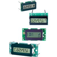
700 - Compteur horaire CURTIS - Free user manual and instructions
Find the device manual for free 700 CURTIS in PDF.


| Product Type | Portable Audio System |
| Model | Curtis 700 |
| Dimensions (W x H x D) | Approximately 30 x 20 x 10 cm |
| Weight | Approximately 2 kg |
| Power Supply | AC 120V / 60Hz or DC 12V (batteries not included) |
| Power Consumption | 15 W |
| Supported Media | CD, MP3, FM/AM radio |
| Speaker Output | 5 W x 2 |
| Display | LED backlit LCD |
| Connectivity | 3.5 mm headphone jack, AV output |
| Main Functions | Play CD/MP3, listen to radio, external device playback |
| Playback Modes | Program, repeat, random |
| Equalizer Presets | Classic, Rock, Pop, Jazz |
| Remote Control | Included, battery CR2025 |
| Antenna | FM wire antenna, AM loop antenna |
| Cleaning and Maintenance | Wipe with dry cloth, avoid liquids |
| Safety | Class II device, do not expose to water |
| Spare Parts Availability | Contact Curtis support for replacement parts |
| Repairability | Repairable by authorized service centers |
| General Information | Designed for home entertainment use |
Frequently Asked Questions - 700 CURTIS
User questions about 700 CURTIS
0 question about this device. Answer the ones you know or ask your own.
Ask a new question about this device
Download the instructions for your Compteur horaire in PDF format for free! Find your manual 700 - CURTIS and take your electronic device back in hand. On this page are published all the documents necessary for the use of your device. 700 by CURTIS.
USER MANUAL 700 CURTIS
5mm HOUR METERS & COUNTERS

Read Instructions Carefully!

SAFETY INSTRUCTIONS
This instrument was manufactured and tested according to the applicable technical standards. It complies with all the safety regulations as shipped from the factory.
Installation and startup must be performed by skilled personnel.
Failure to install and operate the unit in accordance with these instructions may result in damage or injury.
If safe operation of the instrument can no longer be ensured, stop and secure it against accidental operation.
If instrument failure or malfunction may cause personal injury or material damage, use additional safety measures such as limit switches, guards, etc.
Read the Operating Instructions carefully before startup.
Note the safety instructions marked with this warning symbol in this manual!

TABLE OF CONTENTS
- Model Encodement 2
- Technical Specifications
2.1 Electrical 6
2.2 Mechanical 10
2.3 Environmental 12
- Installation 14
- Operation 15
- Troubleshooting 19
- Maintenance 19
- Warranty 20

1. MODEL ENCODEMENT
(All models except 732)
![graph TD A["1"] --> B["Function"] C["2"] --> D["Reset"] E["3"] --> F["Nominal Voltage"] G["4"] --> H["0512D0612A N"] I["5"] --> J["Sequential Code"] K["6"] --> L["Case Style"] M["7"] --> N["24"]](/content/2026/07/1422488/images/2a014a3f249f3020c729019d8c2bcde564d08211376aee43501e64ea15ec88f8.jpg)
1 Function
See section 2.2 for complete specifications.

3 Reset
| R Electrical Reset |
| N No Reset |
4 Sequential Code Factory specified.
5 Nominal Voltage
| 0512D 5 to 12VDC |
| 1248D 12 to 48VDC |
| 48150D 48 to 150VDC |
| 0512D0612A 5 to 12VDC, 6 to 12VAC |
| 1248D2060A 12 to 48VDC, 20 to 60VAC |
| 48150D100230A 48 to 150VDC,100 to 230VAC |
6 Logo
| O Curtis |
| N None |
(See Section 2.1 for absolute voltage)
732 Model Encodement Only
Note: 732 has a built-in LED in its face

1 Case Style
See section 2.2 for complete specifications.

2 Function
| 0 2-wire Hour Meter, no enable; LED gnd-enabled, no reset. |
| 1 2-wire Hour Meter, no enable; LED pwr-enabled, no reset. |
| 2 2-wire Hour Meter, no enable; LED gnd-enabled, w/reset. |
| 3 2-wire Hour Meter, no enable; LED pwr-enabled, w/reset. |
| 4 3-wire Hour Meter, w/enable; LED gnd-enabled, no reset. |
| 5 3-wire Hour Meter, w/enable; LED pwr-enabled, no reset. |
3 LED Voltage (VDC)
| 0 | 12 |
| 1 | 24 |
| 2 | 36 |
| 3 | 48 |
4 Sequential Code Factory specified.
5 Logo
| O Curtis |
| N None |
2. TECHNICAL SPECIFICATIONS

2.1 Electrical
Operating Voltage 700 Series
The operating voltage ranges specified apply to voltages connected between terminal 1 and terminal 2 (700, 701, 703), terminal 3 and terminal 2 (701,703 only), and terminal 4 and terminal 2 (Reset option).
DC only models
| Nominal (VDC) Absolute (VDC) |
| 5 to 12 4.75 to 15 |
| 12 to 48 9.0 to 60 |
| 48 to 150 36 to 185 |
DC/AC models
Nominal (VDC) / Absolute (VDC) : Same as above
| Nominal (VAC) Absolute (VAC) | |
| 6 to 12 5.0 to 15 | |
| 20 to 60 15 to 75 | |
| 100 to 230 75 to 270 |
Operating Voltage 732 Only
Voltages connected between pins 1 and 2 and between 4 and 2 (Enable option).

732 DC only, all voltage models
| Nominal (VDC) Absolute (VDC) |
| 12 to 48 9.0 to 60 |
LED voltages between pins 3 and 2.
| 732 LED Voltage Absolute (VDC) | |
| 12 9 to 15 | |
| 24 18 to 30 | |
| 36 27 to 45 | |
| 48 36 to 60 | |
Frequency (AC models)
The AC operating frequency range is 48 to 440 Hz. Maximum AC-Reset Frequency is 150 Hz.
Accuracy
Model 700, 701, 732 = ±0.1%
Model 703 = ±1 count
Operating Current
(All models except 732)
The maximum operating current at terminal 1 is tabulated below for each nominal operating voltage limit.

DC Only Model
| Operating Voltage (VDC) V+ to V++ | Maximum Current @ V+ | Maximum Current @ V++ |
| 5 to 12 0.5 mA | 10.0 mA | |
| 12 to 48 0.8 mA | 5.0 mA | |
| 48 to 150 0.8 mA | 2.5 mA |
DC/AC Model
VDC: Same as above.
| Operating Voltage (VAC) V+ to V++ | Maximum Current @ V+ | Maximum Current @ V++ |
| 6 to 12 0.7 mA | 6.0 mA | |
| 20 to 60 0.5 mA | 2.5 mA | |
| 100 to 230 0.9 mA | 2.0 mA |
Operating Current continued
(732 Model only)

Single Voltage, DC only
| Operating Voltage (VDC) | Maximum Current w/LED (mA) |
| 12 15.0 | |
| 24 10.0 | |
| 36 7.0 | |
| 48 5.0 |
Impedance
The minimum impedance at terminal 3 and at terminal 4 are tabulated below for each model.
| Voltage Encodement | Impedance (Min) Terminal 3 | Impedance (Min) Terminal 4 |
| 0512D 10 KΩ | 25 KΩ | |
| 1248D 60 KΩ | 70 KΩ | |
| 48150D 480 KΩ | 480 KΩ | |
| 0512D 0612A 10 | KΩ 25 KΩ | |
| 1248D 2060A 70 | KΩ 70 KΩ | |
| 48150D 100230A | 480 KΩ 480 KΩ | |
| 732 (all voltages) – | 70 KΩ |
2.2 Mechanical
Display
6-digit LCD, 5 mm high
Range & Resolution
700, 701, 732 Hour Meters: 99,999.9 Hours
703 Counter: 999,999 Counts.
Case & Connector Specifications

NOTE:
K & N – LED indicator molded in bezel face (available as 732 models only);
H – Require 2-pin Delphi- Packard mating connector P/N 12162000;
J, K & Y – Require 4-pin Delphi- Packard mating connector P/N 12162035;
L - Snap tabs built in (no mounting hardware required); case and bezel 1-piece clear Hexagonal - Screw mount through flange (optionally mounted with plastic bracket, available separately).

| Case Matrl. | Bezel Material | Panel Cutout (mm) | Panel Cutout (in.) |
| 1.45x0.95 | |||
| ABS (black) | ABS (black) | 36.8x24.1 | 1.45x0.95 |
| ABS (black) | ABS (black) | 36.8x24.1 | 1.45x0.95 |
| ABS (black) | ABS (black) | 36.8x24.1 | 1.45x0.95 |
| ABS (black) | ABS (black) | 36.8x24.1 | 1.45x0.95 |
| Abs (black) | ABS (black) | 45x22.2 | 1.77x0.87 |
| Polycarb. | Polycarb. | 36.8x24.1 | 1.45x0.95 |
| ABS (black) | Acrylic (clear) | 36.8x24.1 | 1.45x0.95 |
| ABS (black) | ABS (black) | 36.8x24.1 | 1.45x0.95 |
| ABS (black) | ABS (black) | 36.8x24.1 | 1.45x0.95 |
| Polycarb. | Alum. Anodzd. (blk) | ∅ 52 | ∅ 2 1/16” |
| Polycarb. | Alum. Anodzd. (blk) | ∅ 52 | ∅ 2 1/16” |
2.3 Environmental
Temperature
Operating: -40°C to +85°C
Storage: -50° C to +90° C
Humidity
95% RH (Non Condensing) at 38°C
Shock & Vibration
Meets SAE J 1378
Case - IP Ratings
| Case Style D, Q, R F, Z, N J, Y, H, K L | ||||
| Front 65 65 65 65 | ||||
| Rear 50 65 *65 40 | ||||
* Rated with mating connector installed

EMC
Emissions
Designed to meet: EN 61000-6-4
Radiated Emissions: EN55011:2007, EN55022:2006
Conducted Emissions: EN55011:2007, EN55022:2006
Immunity
Designed to meet: EN 61000-6-2
ESD: EN 61000-4-2:1995
Radiated Immunity
EN 61000-4-3:2006
Transients: EN 61000-4-4:2004
Surge: EN 61000-4-5:2005
Conducted: EN 61000-4-6:2007
Voltage Interruptions: EN 61000-4-11:2004
Regulatory Approvals
UL: UL recognition to UL 583
CE: The product complies with the requirements of the RoHS directive 2015/863/EU (RoHS 3). This product is excluded from CE EMC testing and, if CE marking is required, must only be sold to OEMs completing machine level EMC testing for CE certification.
3. INSTALLATION

| Case Style Pin 1 Pin 2 Pin 3 Pin 4 | |||
| D, F, Q, R, J, Y, Z V+ V- I R | |||
| H V+ V- NC NC | |||
| L V+ V- I NC | |||
| K, N V+ V- LED I | |||
V+: Operating voltage;
V-: Common (ground);
I: Enable (optional, use operating voltage to power this pin to record elapsed time [701] or increment count [703]);
R: Reset (optional, supply with operating voltage when unit is to be reset to 0);
LED: Externally driven by active high or low – factory configured;
NC: No connection;
4. OPERATION
NOTE: All models display an 8 in all digits for 1 sec. at power-up.

To Display & Operate: Apply DC+ or AC hot to pin 1 and DC – or AC neutral to pin 2. The accumulation of elapsed time is indicated by the flashing hourglass icon. If power has been applied for 5 seconds minimum, the accumulated time will be stored in non-volatile memory when power is removed.
To Reset: (for resettable models) Apply DC+ or AC hot to pin 4 for 1/2 second minimum while power (pins 1 & 2) is applied for 5 seconds minimum. The reset voltage must be at the same level as the voltage used to power the unit.
701 Hour Meter (AC/DC or DC Only)
To Display: Apply DC+ or AC hot to pin 1 and DC− or AC neutral to pin 2. The display is activated at this point but the elapsed time will not be accumulated until a signal is applied to pin 3. Note, for proper operation: Power must be applied to pins 1 & 2 before or coincident with pin 3.
701 Hour Meter continued
To Operate: Apply DC+ or AC hot to pin 3 for 1/2 second minimum (AC/DC model) or DC+ for 1 millisecond minimum (DC Only model). The accumulation of elapsed time is indicated by the flashing hourglass icon. If power (pins 1 & 2) has been applied for 5 seconds minimum, the accumulated time will be stored in non-volatile memory when power is removed.

To Reset: (for resettable models) Apply DC+ or AC hot to pin 4 for 1/2 second minimum while power (pins 1 & 2) is applied for 5 seconds minimum. The reset voltage must be at the same level as the voltage used to power the unit.
703 Counter (AC/DC or DC Only)
To Display: Apply DC+ or AC hot to pin 1 and DC – or AC neutral to pin 2. The display is activated at this point but the count will not be started until a signal is applied to pin 3. Note, for proper operation: Power must be applied to pins 1 & 2 before or coincident with pin 3.
To Operate: Apply DC+ or AC hot to pin 3. The count is incremented when the input signal is removed from pin 3.
703 Counter continued
The input signal must be applied for 1/2 second minimum (AC/DC model) or for 1 millisecond minimum (DC Only model). If power (pins 1 & 2) has been applied for 5 seconds minimum, the incremented count will be stored in non-volatile memory when power is removed.
To Reset: (for resettable models) Apply DC+ or AC hot to pin 4 for 1/2 second minimum while power (pins 1 & 2) is applied for 5 seconds minimum. The reset voltage must be at the same level as the voltage used to power the unit.
732 Hour Meter (DC Only)
To Activate Display: Apply DC+ to pin 1 and DC- to pin 2.
To Activate LED: Apply DC+ (for active-high models) or DC- (for active-low models) to pin 3 during indicator-on condition.
To Activate Elapsed Time: For models without separate enable option - elapsed time is activated when power is applied to pins 1 & 2. For models with enable option - apply signal to pin 4. Note: Power (to pins 1 & 2) must be applied before or at the same time as signal to pin 4.

732 Hour Meter continued
Operation: Apply DC+ to pin 4 for 1 millisecond minimum. Activation (accumulation) of elapsed time is indicated by the hourglass icon flashing. Time accumulated will be stored into non-volatile memory when power is removed, if power (to pins 1 & 2) has been applied for the minimum of 5 seconds.
Reset: (for resettable models), Apply DC+ to pin 4 for 1/2 second minimum, while power to pins 1 & 2 has been applied for 5 seconds minimum. Note: The reset voltage must be at the same level as the voltage used to power the unit.

5. TROUBLESHOOTING

To maximize the life of this meter, please read all instructions carefully and review Safety Precautions on inside front cover of this manual. Most minor problems can be resolved by removing all power for at least 10 seconds and then reconnecting.
| Problem Possible Cause | |
| No Display Power not connected | or too low. |
| Display Present, but counter does not activate. | Input (or enable) wire not connected. Start Input not connected. Input voltage not reaching specified minimum signal level. |
| LED not turning ON during activation condition. | Switch or switch-connection faulty. |
6. MAINTENANCE
Curtis Model 700 & 732 Series hour meters are not serviceable in the field. Units returned to the factory within the warranty period (see inside back cover) will be replaced without charge.
7. WARRANTY

Curtis Instruments’ products and/or components are guaranteed against defects in workmanship and material for a period of two years, or as defined in the individual product literature, from date of shipment from our factory, when applied in a proper application within specified ratings. This guarantee is limited to repair or replacement F.O.B. our factory. There is no further warranty or implied representation, guarantee, promise or agreement as to any Curtis Instruments product and/or component. Curtis Instruments, Inc., can not assume responsibility or accept invoices for unauthorized repairs to its products and/or components, even though defective. In no case will Curtis Instruments’ responsibility extend to products, components or equipment not of its manufacture. Under no circumstances shall Curtis Instruments, Inc., be liable for any special or consequential damages or loss of profits or other damages. Returned goods will not be accepted unless identified by a Curtis Return Material Authorization (RMA).
All specifications are subject to change without notice.

CURTIS
CURTIS INSTRUMENTS, INC.
200 Kisco Ave.
Mount Kisco, New York 10549
914-666-2971 Tel
914-666-2188 Fax
www.curtisinstruments.com
53004 Rev. I 3/21
- 5MM HOUR METERS & COUNTERS
- SAFETY INSTRUCTIONS
- TABLE OF CONTENTS
- MODEL ENCODEMENT
- (ALL MODELS EXCEPT 732)
- 1 FUNCTION
- 3 RESET
- 4 SEQUENTIAL CODE FACTORY SPECIFIED
- 5 NOMINAL VOLTAGE
- 6 LOGO
- 732 MODEL ENCODEMENT ONLY
- 1 CASE STYLE
- 2 FUNCTION
- 3 LED VOLTAGE (VDC)
- TECHNICAL SPECIFICATIONS
- 2.1 ELECTRICAL
- OPERATING VOLTAGE 700 SERIES
- OPERATING VOLTAGE 732 ONLY
- FREQUENCY (AC MODELS)
- ACCURACY
- OPERATING CURRENT
- DC/AC MODEL
- OPERATING CURRENT CONTINUED
- (732 MODEL ONLY)
- IMPEDANCE
- 2.2 MECHANICAL
- DISPLAY
- RANGE & RESOLUTION
- CASE & CONNECTOR SPECIFICATIONS
- NOTE
- 2.3 ENVIRONMENTAL
- TEMPERATURE
- HUMIDITY
- SHOCK & VIBRATION
- CASE - IP RATINGS
- EMC
- EMISSIONS
- IMMUNITY
- RADIATED IMMUNITY
- REGULATORY APPROVALS
- INSTALLATION
- OPERATION
- 701 HOUR METER (AC/DC OR DC ONLY)
- 701 HOUR METER CONTINUED
- 703 COUNTER (AC/DC OR DC ONLY)
- 703 COUNTER CONTINUED
- 732 HOUR METER (DC ONLY)
- 732 HOUR METER CONTINUED
- TROUBLESHOOTING
- MAINTENANCE
- WARRANTY
- ALL SPECIFICATIONS ARE SUBJECT TO CHANGE WITHOUT NOTICE
- CURTIS INSTRUMENTS, INC
Brand : CURTIS
Model : 700
Category : Compteur horaire