
Leon VZe - Automobile Cupra - Free user manual and instructions
Find the device manual for free Leon VZe Cupra in PDF.


| Type de produit | Plug-in Hybrid Vehicle (PHEV) |
| Dimensions (L x l x H) | Approx. 4368 mm x 1799 mm x 1441 mm |
| Wheelbase | 2686 mm |
| Curb weight | Approx. 1550 kg |
| Power source | 1.4L TSI petrol engine + electric motor (combined 180 kW / 245 hp) |
| Battery capacity | 12.8 kWh (lithium-ion) |
| Electric range (WLTP) | Up to 64 km |
| Charging time (3.6 kW wallbox) | Approx. 3.5 hours (full charge) |
| Transmission | 6-speed DSG automatic |
| Drivetrain | Front-wheel drive |
| Top speed (electric mode) | 140 km/h |
| Fuel tank capacity | 40 L |
| Key driving modes | E-Mode, Hybrid, GTE (performance), Cupra |
| Regenerative braking | Adjustable levels via steering wheel paddles |
| Safety features | Front & side airbags, ESC, adaptive cruise control, lane assist |
| Maintenance interval | Every 15,000 km or 1 year (whichever first) |
| Battery warranty | 8 years or 160,000 km (subject to conditions) |
| Spare parts availability | OEM parts available at Cupra dealerships |
| Repairability | Modular components, high-voltage system requires certified technician |
| General notes | Homologated as passenger car, varies by region |
Frequently Asked Questions - Leon VZe Cupra
User questions about Leon VZe Cupra
0 question about this device. Answer the ones you know or ask your own.
Ask a new question about this device
Download the instructions for your Automobile in PDF format for free! Find your manual Leon VZe - Cupra and take your electronic device back in hand. On this page are published all the documents necessary for the use of your device. Leon VZe by Cupra.
USER MANUAL Leon VZe Cupra
CUPRA FORMENTOR
OWNER'S MANUAL

CUPRA
Vehicle identification data
| Model: |
| Vehicle Registration: |
| Vehicle identification number: |
| Date of vehicle registration or vehicle delivery: |
| SEAT Official Service/CUPRA authorised service: |
| Service advisor: |
| Telephone: |
Confirmation of receipt of documentation and vehicle keys
| The following items were delivered with the vehicle: | YES NO | |
| On-board documentation | ||
| First key | ||
| Second key | ||
| Correct working order of all keys was checked | ||
| Location:Date: | ||
| Signature of owner: | ||
Introduction
Thank you for your trust choosing a CUPRA vehicle.
With your new CUPRA, you will be able to enjoy a vehicle with state-of-the-art technology and top quality features.
We recommend reading this Instruction Manual carefully to learn more about your vehicle so you can enjoy all its benefits in your daily driving.
Information about handling is complemented with instructions regarding the operation and maintenance of the vehicle in order to ensure its safety and maintain its value. Moreover, we want to give you valuable advice and tips to drive your vehicle efficiently and respecting the environment.
We wish you safe and enjoyable motoring.
CUPRA
WARNING
Read and always observe safety information concerning the passenger's front airbag» page 33, Fitting and using child seats.
About this manual
This instruction manual is valid for all variants and versions of your CUPRA model. It describes all equipment and models without specifying whether they are optional equipment or model variants. As a result, equipment not fitted to your vehicle or only available in certain countries may be described. Find out about your vehicle's equipment in the documentation supplied with it and please contact your CUPRA Specialised Service or SEAT Official SEAT Service if you require more detailed information.
All information provided in instruction manual corresponds to the information available at the time of going to press. As the vehicle is under continuous development, it may have differences to the data included in this manual. For this reason, no claims can be made in the event of mismatching data, illustrations and descriptions.
Ensure that the on-board documentation is kept in the vehicle at all times if you sell it or lend it to third parties. In addition, CUPRA recommends resetting the infotainment system to factory settings to delete all personal data.
Some details on the drawings may vary from its vehicle and must be interpreted as a standard representation.
The direction indicators (left, right, forwards, backwards) in this manual refer to the travel direction of the vehicle unless otherwise stated.
This instruction manual has been written for left-hand drive vehicles. In right-hand drive vehicles, the arrangement of the controls differs partly from that shown in the illustrations or described in the texts.
Technical modifications to the vehicle or safety-critical issues that have arisen since the time of going to press will be included in a supplement to the on-board documentation.
® Trademarks are marked with ®. The absence of this symbol does not guarantee that the term is not a trademark.
It indicates that the section continues on the next page.
You can access the information in this manual using:
- Thematic table of contents that follows the manual's general chapter structure.
- Visual table of contents that uses graphics to indicate the pages containing "essential" information, which is detailed in the corresponding chapters.
- Alphabetical index with many terms and synonyms to help you find information.

WARNING
Texts after this symbol contain information about safety and warn you about possible accident or injury risks.

CAUTION
Texts after this symbol indicate possible damage to the vehicle.

For the sake of the environment
Texts after this symbol contain information about the protection of the environment.

Note
Texts after this symbol contain additional information.
Digital instruction manual
The digital version of the manual can be found on the official CUPRA website:
Fig. 1 CUPRA website
- scan the QR code>>> Fig. 1
- OR enter the following address in the navigator website:
http://www.cupraofficial.com/owners/cupra-car-model-manuals.html
and select your vehicle.
Valid for the Dutch market
Only CUPRA Specialized Services can repair CUPRA vehicles and provide services under warranty.
Table of Contents
Table of Contents
General views of the vehicle .....7
Exterior view....7
Exterior view 8
Overview (left hand drive)....9
Overview (right hand drive)....10
Interior view....11
Safety 12
Safe driving 12
Advice about driving 12
Correct sitting position of vehicle occupants....
Pedal area....16
Seat belts 16
The whys and wherefores of seat belts .... 16
How to properly adjust your seat belt ..... 19
Seat belt tensioners 21
PreCrash system....22
Airbag system....23
Brief introduction 23
Operation of the airbags 25
Transporting children safely 31
Child safety 31
Emergencies 42
Self-help 42
Information, assistance and emergency
call service 42
Emergency equipment 43
Tyre repairs 44
Changing a wheel 46
Changing the windscreen wiper blades .... 50
Jump start....52
Tow start and towing....53
Fuses and bulbs 58
Fuses....58
Changing bulbs 61
Operation 63
Controls and displays 63
Interior view....63
Instruments and warning/control
lamps....64
Instrument panel 64
Using the instrument panel....80
Control lamps 82
Infotainment system 85
Multifunction steering wheel 91
Opening and closing 92
Set of vehicle keys 92
Central locking 95
Anti-theft alarm system 101
Doors 104
Rear lid 105
Window controls 110
Sunroof 112
Lights 114
Vehicle lighting 114
Interior lights 121
Visibility 123
Windscreen wiper and rear window wiper
systems 123
Mirrors 125
Sun protection 128
Seats and headrests 128
Adjusting seats 128
Headrest 130
Seat functions 131
Transport and practical equipment ..... 134
Storing objects 134
Luggage compartment 136
Roof carrier 140
Storage compartment 142
Power sockets 145
Air conditioning.... 147
Heating, ventilation and cooling ..... 147
auxiliary heating (additional heating) ..... 156
Stationary air conditioning.... 159
Infotainment system 162
Introduction 162
First steps 162
Overview and controls 166
General instructions for use 167
Data transfer 173
CUPRA CONNECT 173
Full Link 178
WLAN access point 182
Infotainment operation 184
voice control 184
Radio mode 186
Media Mode 190
Navigation 193
Telephone interface 200
Multimedia 206
Driving 207
Start and driving 207
Starting and stopping the engine 207
Driving with electric drive 211
Table of Contents
Operating mode selection ..... 213
Start-Stop system 214
Manual gearbox....217
DSG automatic transmission....218
Gear-change recommendation ..... 224
Hill Descent Control (HDC) 225
Steering 225
Driving modes (Drive Profile) 226
Driving tips 229
Driver assistance systems 232
General notes 232
Driver assistance sensors and cameras . . . 233
Cruise control system (CCS) 236
Speed limiter 238
emergency brake assistance system (Front
Assist) 240
ACC - Adaptive Cruise Control ..... 244
Proactive speed adjustment 250
Lane Assist 252
Driving Assist (Travel Assist) 254
Emergency Assist 256
Lane departure warning (Side Assist) with
rear cross traffic alert (RCTA) and door
opening warning (Exit Assist) 258
Braking and parking 264
Braking system 264
Stabilisation and brake assistance sys-
tems 269
Parking 273
Help with parking and manoeuvring ..... 27
Assisted parking system (Park Assist) ..... 274
Parking aid parking and manoeuvring
(ParkPilot) 281
Parking System Plus 282
Rear parking aid 285
Peripheral view system (Top View Cam-
era)....286
Reverse Assist (Rear View Camera) ..... 288
Towing bracket device 291
Trailer mode 291
Electrically unlocking trailer hook ..... 298
Retrofitting a towing bracket 300
Battery 302
High-voltage battery 302
Safety instructions....302
Conservation of the high-voltage bat-
tery 304
Charging settings in the infotainment sys-
tem 305
Charging the high-voltage battery ..... 306
Charging cable 311
Practical tips 315
Checking and refilling levels 315
Refuelling....315
Fuel types 317
AdBlue ® 318
Engine management and emissions con-
trol system 320
Engine compartment 322
Engine oil 326
Cooling system 329
Brake fluid 331
Windscreen washer reservoir 332
12-volt battery 333
Energy management 337
Wheels 339
Wheels and tyres 339
Tyre pressure monitor system 346
Spare wheel 347
Maintenance 350
Service 350
Service intervals 350
Additional service offers 352
Warranty 353
Vehicle maintenance 353
Maintenance and cleaning 353
Accessories and modifications to the ve-
hicle 359
Accessories, spare parts and repair work .. 359
Information for the user 361
Information for the user 361
Information stored by the control units . . . 361
Other important information 361
Information about the EU Directive
2014/53/EU 362
Technical data 367
Indications about the technical data .... 367
Important information 367
Index 373
General views of the vehicle
Exterior view

Driving assistance sensors >> page 232
① Front multifunction camera
② Rear-view cameras "Area View"
③ Front camera "Area View"
④ Front radar
⑤ Park distance control sensors
⑥ Park assist sensor
A Levels control
- Oil >> page 326
- Brake fluid>>> page 331
- Battery >> page 333
B Bonnet
- Unlocking lever>>> page 324
- Open/close>>> page 324
© Towing the vehicle
- Towline anchorage»» page 56
- Tow-start>>page 54
D Charging socket (hybrid vehicles)
- Charging process display»» page 309
- Emergency unlocking>>> page 311
General views of the vehicle
Exterior view

SFF-0035
Driving assistance sensors >> page 232
① Rear view camera
② Park distance control sensors
③ Rear radars
4 Park assist sensor
A Rear lid
- Opening from outside >> page 106
– Emergency opening>>> page 110
B Towing the vehicle
- Towline anchorage»» page 56
- Tow-start>> page 54
© Opening and closing
- Doors >> page 104
- Central locking>>> page 95
- Emergency lock>>>page 104
D Fuel tank
- Fuel capacity>>>page 367
- Open/Close cap>> page 315
E Action in the event of a puncture
- Anti-puncture kit>>page 44
- Wheel change>>page 46
General views of the vehicle
Overview (left hand drive)

① Electric windows>>> page 110
② Exterior mirror adjustment>> page 125
③ Control for lighting and demisting windows» page 115
④ Turn signal and main beam lever >> page 116
⑤ Warning lamps»» page 82
⑥ Wipers and rear window wiper >> page 123
⑦ Driver information system»» page 80
⑧ Infotainment system»» page 85, >> page 162
⑨ Open bonnet lever» page 324
⑩ Fuses>>> page 58
⑪ Steering wheel adjustment»» page 15
12 Hazard warning lights»» page 120
⑬ ESC start» page 207 stop button
page 272
14 Electronic parking brake»»page 266
15 Central locking>> page 95
General views of the vehicle
Overview (right hand drive)

① Infotainment system»» page 85, >> page 162
② Turn signal and main beam lever >> page 116
③ Warning lamps»» page 82
④ Wipers and rear window wiper >> page 123
⑤ Driver information system»» page 80
⑥ Control for lighting and demisting windows» page 115
⑦ Exterior mirror adjustment>>>page 125
⑧ Electric windows»» page 110
⑨ Open bonnet lever»» page 324
⑩ ESC start>>> page 207 stop button
page 272
⑪ Central locking>>>page 95
⑫ Electronic parking brake» page 266
13 Hazard warning lights»» page 120
14 Steering wheel adjustment >>> page 15
15 Fuses >> page 58
General views of the vehicle
Interior view

① Armrest» page 140
② Isofix anchors»»page 34
③ Seat belts>> page 16
④ Panoramic roof>> page 112
⑤ Interior mirror»»page 125
⑥ Disconnecting the front passenger front airbag»»page 27
⑦ Electronic parking brake»»page 266
⑧ Seat adjustment>>> page 128
Safety
Safety
Safe driving
Advice about driving
Safety first!
WARNING
- This manual contains important information about the operation of the vehicle, both for the driver and the passengers. The other sections of the on-board documentation also contain further information that you should be aware of for your own safety and for the safety of your passengers.
- Ensure that the on-board documentation is kept in the vehicle at all times. This is especially important when lending or selling the vehicle to another person.
Before driving
For your own safety and the safety of your passengers, always note the following points before every trip:
- Make sure that the vehicle's lights and turn signals are working properly.
-
Check tyre pressure.
-
Ensure that all windows provide a clear and good view of the surroundings.
- Make sure all luggage is secured >> page 134.
- Make sure that no objects can interfere with the pedals.
- Adjust front seat, headrest and mirrors properly according to your size.
- Ensure that the passengers in the rear seats always have the headrests in the in-use position» page 130.
- Instruct passengers to adjust the headrests according to their height.
- Protect children with appropriate child seats and properly applied seat belts » page 31.
- Assume the correct sitting position. In-struct your passengers also to assume a proper sitting position»»page 13.
- Fasten your seat belt securely. Instruct your passengers also to fasten their seat belts properly»»page 16.
Factors influencing safety
As a driver, you are responsible for yourself and your passengers.
- Always pay attention to traffic and do not get distracted by passengers or telephone calls.
- Never drive when your driving ability is impaired (e.g. by medication, alcohol, drugs).
- Observe traffic laws and speed limits.
- Always reduce your speed as appropriate for road, traffic and weather conditions.
- When travelling long distances, take breaks regularly - at least every two hours.
- If possible, avoid driving when you are tired or stressed.
WARNING
Driving under the influence of alcohol, drugs, medication or narcotics may result in severe accidents and even loss of life.
• Alcohol, drugs, medication and narcotics may significantly alter perception, affect reaction times and safety while driving, which could result in the loss of control of the vehicle.
Safety equipment
Never put your safety or the safety of your passengers in danger. In the event of an accident, the safety equipment may reduce the risk of injury. The following points cover
Safe driving
part of the safety equipment in your CU-PRA 1) :
• three-point seat belts,
- belt tension limiters for the front and rear side seats,
- belt tensioners for the front and rear side seats,
- front airbags,
- knee and central driver airbags
• side airbags in the front seat backrests,
• side airbags in the rear seat backrests,
• head-protection airbags,
- "ISOFIX" anchor points on the front passenger seat and on the rear seats for child seats with the "ISOFIX" system,
• height-adjustable front head restraints 2) ,
• rear headrests with in-use position and non-use position,
• adjustable steering column.
The safety equipment mentioned above works together to provide you and your passengers with the best possible protection in the event of an accident. However, these safety systems can only be effective if you
and your passengers are sitting in a correct position and use this equipment properly.
Safety is everyone's business!
Correct sitting position of vehicle occupants
Correct position on the seat

Fig. 2 The correct distance between the driver and the steering wheel must be at least 25 cm (10 inches).
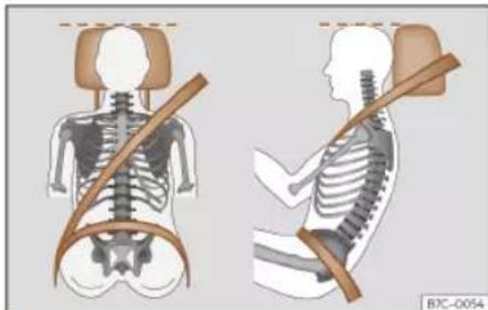
Fig. 3 Correct belt web and headrest positions
The correct sitting positions for the driver and passengers are shown below.
If your physical constitution prevents you from maintaining the correct sitting position, contact a specialised workshop for help with any special devices. The seat belt and airbag can only provide optimum protection if a correct sitting position is adopted. CUPRA recommends taking your car in for technical service.
For your own safety and to reduce the risk of injury in the event of an accident or sudden braking or manoeuvre, CUPRA recommends the following positions:
Safety
Valid for all vehicle occupants:
- Adjust the headrest so that its upper edge is at the same level as the top of your head, or as close as possible to the same level as the top of your head and under no circumstances below eye level. Keep the back of your neck as close as possible to the head-rest>> Fig. 3.
- Short people must lower the headrest completely, even if your head is below its upper edge.
- Tall people must raise the headrest completely.
• Always keep your feet in the footwell while the vehicle is in motion. - Adjust and fasten your seat belt correctly >> page 19.
The following also applies to the driver:
- Move the seat backrest to an almost upright position so that your back rests completely against it.
- Move the steering wheel so it is at least 25 cm (10 inches) away from the sternum»» Fig. 2 and you can hold it with both hands on both sides, on the outer part, with your arms slightly bent.
- The steering wheel must always point towards the chest and never towards the face.
- Move the seat in such a way that you can step on the pedals with your knees slightly
bent and with a distance between the knees and the dashboard of at least 10 cm (4 inches)>>> Fig. 2.
- Adjust the height of the seat so that you can reach the top of the steering wheel.
• Always keep both feet in the footwell so that you have the vehicle under control at all times.
For the passenger, the following applies:
- Move the seat backrest to an almost upright position so that your back rests completely against it.
- Move the seat as far back as possible (minimum 25 cm between the chest and the dashboard check translation). If you are sitting closer than 25 cm, the airbag system cannot protect you properly.
Number of seats
The vehicle has 5 seats, 2 in the front and 3 in the rear. All seats are equipped with a safety belt.
In some versions, your vehicle is approved only for 4 seats. 2 front seats and 2 rear seats.
WARNING
Sitting in an incorrect position may increase the risk of severe or lethal injuries in
the event of sudden braking or manoeuvring, in case of collision or accident and if the airbags deploy.
- Before starting the car, all passengers must be sitting in a correct position and stay like that for the entire journey. This also applies to a correct use of the seat belt.
- The maximum amount of people in the vehicle is the same as the amount of seats with seat belts.
- For children, always use a certified protection system, certified and suited for their weight and height» page 31.
- While driving, always keep your feet in the footwell. Never place them over the seat or the dashboard, for example, or outside the window. Otherwise the airbag and seat belt may offer insufficient protection and also increase the risk of injury in the event of an accident.
Risks of sitting in an incorrect position
If seat belts are worn incorrectly or not at all, the risk of severe or lethal injuries increases. Seat belts can provide optimal protection only if the belt web is properly worn. Incorrect sitting positions substantially reduce the protective function of seat belts and, therefore, increase the risk of severe or even lethal injuries. The risk of severe or fatal
Safe driving
injuries is especially heightened when a deploying airbag strikes a vehicle occupant who has assumed an incorrect sitting position. The driver is responsible for all people, particularly children, inside the vehicle.
The following list contains examples of incorrect sitting positions that could be dangerous for all vehicle occupants.
When the vehicle is in motion:
• Never stand in the vehicle.
• Never stand on the seats.
• Never kneel on the seats.
- Never tilt your seat backrest too far to the rear.
• Never lean against the dash panel.
• Never lie on the rear seats.
- Never sit on the front edge of a seat.
- Never sit sideways.
• Never lean out of a window.
• Never put your feet out of a window.
- Never put your feet on the dash panel.
- Never place your feet on the bench or on the backrest of the seat.
• Never travel in a footwell.
- Never sit on the armrests.
- Never travel without wearing the seat belt.
- Never travel in the luggage compartment.
WARNING
Sitting in an incorrect position increases the risk of severe or fatal injuries in the event of accidents and sudden braking or manoeuvres.
- All occupants must sit correctly during the journey and wear the seat belt correctly.
- Occupants of the vehicle that are not sitting correctly, not wearing the seat belt or are not at a proper distance of the airbag risk suffering very serious or lethal injuries, especially if the airbags deploy and strike them.
Steering wheel position adjustment
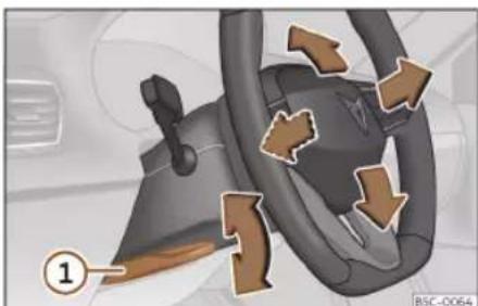
Fig. 4 Lever in the lower left side of the steering column.
Adjust the steering wheel before your trip and only when the vehicle is stationary.
- Pull the>> Fig. 4 ① lever down, move the steering wheel to the desired position and lift the lever back up until it locks.
WARNING
Incorrect use of the steering wheel adjustment function and an incorrect adjustment of the steering wheel can result in severe or fatal injury.
- After adjusting the steering column, push the lever>>Fig. 4 ① firmly upwards to ensure the steering wheel does not accidentally change position while driving.
- Never adjust the steering wheel while the vehicle is in motion. If you need to adjust the steering wheel while the vehicle is in motion, stop safely and make the proper adjustment.
- The adjusted steering wheel should be facing your chest and not your face so as not to hinder the driver's front airbag protection in the event of an accident.
- When driving, always hold the steering wheel with both hands on the outside of the ring at the 9 o'clock and 3 o'clock positions to reduce injuries when the driver's front airbag deploys.
- Never hold the steering wheel at the 12 o'clock position or in any other manner (e.g. in the centre of the steering wheel). In such cases, if the driver's airbag deploys,
Safety
you may sustain injuries to your arms, hands and head.
Pedal area
Pedals
- Ensure that you can always press the accelerator, brake and clutch pedals unimpaired to the floor.
- Ensure that the pedals can return unimpaired to their initial positions.
- Ensure that the floor mats are securely fastened during the trip and do not obstruct the pedals >>> △.
Only use floor mats which leave the pedals clear and which are secured to prevent them from slipping. You can obtain suitable floor mats from a specialised dealership. Fasteners for floor mats are fitted in the footwells.
If a brake circuit fails, the brake pedal must be pressed down thoroughly in order to stop the vehicle.
Wear suitable footwear
Always wear shoes which support your feet properly and give you a good feeling for the pedals.
WARNING
- Restricting pedal operation can lead to critical situations while driving.
- Never lay or fit floor mats or other floor coverings over the original floor mats. This would reduce the pedal area and could obstruct the pedals. Risk of accident.
- Never place objects in the driver footwell. An object could move into the pedal area and impair pedal operation.
Seat belts
The whys and wherefores of seat belts
Control lamps
It lights up red
The driver or one of the passengers have not fastened their seat belts.
The control lamp lights up to remind the driver to fasten their seat belt.
Before starting the vehicle:
- Fasten your seat belt securely.
- Instruct your passengers to fasten their seat belts properly before driving off.
- Protect children by using a child seat according to the child's height and weight » page 31.
When starting to drive, if the vehicle's speed exceeds approx. 25 km/h (15 mph) and the seat belts are not fastened or are unfastened while driving, a warning sound will be heard for a few seconds. The warning light will also flash.
The lamp 4/5 goes out when the ignition is on and all occupants have fastened their seat belts.
Seat belts
Rear seat belts fastened display
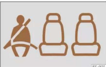
Fig. 5 Instrument panel: left rear seat occupied and corresponding seat belt fastened display.
Depending on the model version, when the ignition is switched on, the seat belt status display» Fig. 5 on the instrument panel informs the driver whether the passengers in the rear seats have fastened their seat belts.

It indicates that the corresponding seat is empty.

Indicates that the seat is occupied and the occupant is wearing the seat belt.
The seat belt status symbol will light up for a maximum of 60 seconds when a seat belt in the rear seats is unfastened while the vehicle is in motion. An audible warning will also be heard if the vehicle is travelling at over 25 km/h (15 mph).
If a seat belt is fastened or unfastened while driving in some of the rear seats, the seat belt status is displayed for approximately 60 seconds.
The protective function of seat belts

Fig. 6 Drivers with properly worn seat belts will not be thrown forward in the event of sudden braking.
Properly worn seat belts hold the occupants in the proper position. They also help prevent uncontrolled movements that may result in serious injury and reduce the risk of being thrown out of the vehicle in case of an accident.
Vehicle occupants wearing their seat belts correctly benefit greatly from the ability of the belts to absorb kinetic energy. In addition, the front part of your vehicle and other
passive safety features (such as the airbag system) are designed to absorb the kinetic energy released in a collision. Taken together, all these features reduce the releasing kinetic energy and consequently, the risk of injury. This is why it is so important to fasten seat belts before every trip, even when "just driving around the corner".
Ensure that your passengers wear their seat belts as well. Accident statistics have shown that wearing seat belts is an effective means of substantially reducing the risk of injury and improving the chances of survival when involved in a serious accident. Furthermore, properly worn seat belts improve the protection provided by airbags in the event of an accident. For this reason, wearing a seat belt is required by law in most countries.
Although your vehicle is equipped with airbags, the seat belts must be fastened and worn. The front airbags, for example, are only triggered in some cases of head-on collision. The front airbags will not be triggered during minor frontal or side collisions, rear-end collisions, overturns or accidents in which the airbag trigger threshold value in the control unit is not exceeded.
Safety
Important safety instructions for the use of seat belts
- Always wear the seat belt as described in this section.
- Ensure that the seat belts can be fastened at all times and are not damaged.

WARNING
• If seat belts are worn incorrectly or not at all, the risk of severe injuries increases. The optimal protection from seat belts can be achieved only if you use them properly.
- Never allow two passengers (even children) to share the same seat belt.
- Never unbuckle a seat belt while the vehicle is in motion. Risk of fatal injury.
- The seat belt should never lie on hard or fragile objects (such as glasses or pens, etc.) because this can cause injuries.
- Do not allow the seat belt to be damaged or jammed, or to rub on any sharp edges.
- Never wear the seat belt under the arm or in any other incorrect position.
- Bulky and unfastened clothing (such as an overcoat over a sweater) impairs the proper fit and function of the seat belts, reducing their capacity to protect.
- The slot in the seat belt buckle must not be blocked with paper or other objects, as this can prevent the latch plate from engaging securely.
- Never use seat belt clips, fastening rings or similar items to alter the position of the belt webbing.
- Frayed or torn seat belts or damage to the connections, belt retractors or parts of the buckle could cause severe injuries in the event of an accident. Therefore, you must check the condition of all seat belts at regular intervals.
- Seat belts which have been worn in an accident and have been stretched must be replaced by a specialised workshop. Renewal may be necessary even if there is no apparent damage. The belt anchorage should also be checked.
- Do not attempt to repair a damaged seat belt yourself. The seat belts must not be removed or modified in any way.
- The belts must be kept clean, otherwise the retractors may not work properly.
Head-on collisions and the laws of physics

Fig. 7 A driver not wearing a seat belt is thrown forward violently.

Fig. 8 The unbelted passenger in the rear seat is thrown forward violently, hitting the driver who is wearing a seat belt.
The effects of the laws of physics in the case of a head-on collision are easy to explain: the moment a vehicle starts moving, a type of energy called "kinetic energy" starts
Seat belts
acting on both the vehicle and its passengers.
The amount of "kinetic energy" depends on the speed of the vehicle and on the weight of the vehicle and of its passengers. The higher they are, the more energy there is to be "absorbed" in the event of an accident.
The most significant factor, however, is the speed of the vehicle. If the speed doubles from 25 km/h (15 mph) to 50 km/h (30 mph), for example, the corresponding kinetic energy is multiplied by four.
Given that the passengers of the vehicle in our example do not have their seat belts fastened, in the event of a collision the entire amount of the passengers' kinetic energy will be only absorbed by the mentioned impact.
Even at speeds of 30 km/h (19 mph) to 50 km/h (30 mph), the forces acting on bodies in a collision can easily exceed one tonne (1000 kg). At greater speed these forces are even higher.
Vehicle occupants not wearing seat belts are not "attached" to the vehicle. In a head-on collision, they will move forward at the same speed their vehicle was travelling just before the impact. This example applies not only to head-on collisions, but to all accidents and collisions.
Even at low speeds the forces acting on the body in a collision are so great that it is not
possible to brace oneself with one's hands. In a frontal collision, unbelted passengers are thrown forward and will make violent contact with the steering wheel, dash panel, wind-screen or whatever else is in the way >> Fig. 7.
It is also important for rear passengers to wear seat belts properly, as they could otherwise be thrown forward violently through the vehicle interior in an accident. Passengers in the rear seats who do not use seat belts endanger not only themselves but also the front occupants» Fig. 8.
How to properly adjust your seat belt
Fastening and unfastening the seat belt
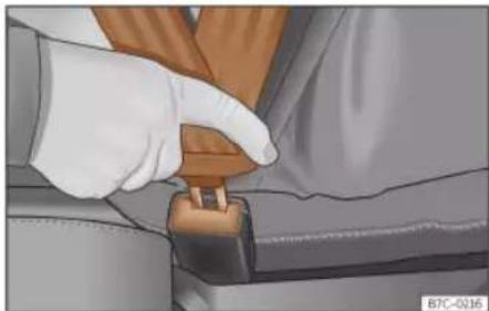
Fig. 9 Insert the latch plate of the seat belt into the buckle.

Fig. 10 Release the seat belt's buckle.
Safety
Properly worn seat belts hold the vehicle occupants in the position that most protects them in the event of an accident or sudden braking >> △.
Fastening the seat belt
Fasten your seat belt before each trip.
- Adjust the front seat and headrest correctly >> page 13.
- Engage the seat backrest of the rear seat in an upright position »» △.
- Pull the latch plate and place the belt webbing evenly across your chest and lap. Do not twist the seat belt when doing so >> ▲.
- Engage the latch plate in the buckle of the corresponding seat>> Fig. 9.
- Pull the belt to ensure that the latch plate is securely engaged in the buckle.
Releasing the seat belt
Only unfasten the seat belt when the vehicle has come to a standstill >> △.
- Press the red button on the buckle >> Fig. 10. The latch plate is released from the buckle.
• Guide the belt back by hand so that it rolls up easily and the trim will not be damaged.
WARNING
- The seat belt cannot offer its full protection unless the seat backrest is in an upright position and the seat belt is worn correctly, according to your size.
- Unbuckling your seat belt while the vehicle is in motion can cause severe or fatal injuries in the event of an accident or sudden braking.
• The seat belt itself, or a loose seat belt, can cause severe injuries if the belt moves from hard areas of the body to soft areas (e.g. the stomach).
Correct seat belt position

Fig. 11 Correct seat belt and headrest positions, viewed from front and the side.

Fig. 12 Position of seat belt during pregnancy.
Seat belts offer their maximum protection in the event of an accident and reduce the risk of sustaining severe or fatal injuries only when they are properly positioned. Furthermore, if the webbing is correctly positioned, the seat belt will hold the vehicle occupants in the optimum position to ensure the airbag provides the maximum protection. The seat belt must therefore always be worn and the webbing correctly positioned.
Incorrectly worn seat belts can cause severe or even fatal injuries»» page 13, Correct sitting position of vehicle occupants.
• The shoulder part of the seat belt must lie on the centre of the shoulder, never across the neck or the arm, under the arm or behind the shoulder.
Seat belts
• The lap part of the seat belt must lie across the pelvis, never across the stomach.
- The seat belt must lie flat and fit comfortably. Pull the belt tight if necessary to take up any slack.
In the case of pregnant women, the seat belt must lie evenly across the chest and as low as possible over the pelvis, never across the stomach and must be worn properly at all times during the pregnancy>> Fig. 12.
Adapting the position of the belt webbing to your size
The position of the seat belt can be adapted by adjusting the height of the front seats.
WARNING
An incorrectly worn seat belt web can cause severe or fatal injuries in the event of an accident.
- The shoulder part of the seat belt must lie on the centre of the shoulder, never across the neck or the arm.
- The seat belt must lie flat and fit comfortably on the torso
- The lap part of the seat belt must lie across the pelvis, never across the stomach. The seat belt must lie flat and fit comfortably on the pelvis Pull the belt tight if necessary to take up any slack.
- For pregnant women, the lap part of the seat belt must lie as low as possible over the
pelvis and always lie flat, "surrounding" the stomach>> Fig. 12.
- Do not twist the seat belt while it is fastened.
- Once the seat belt is positioned correctly, don't pull it away from your body with your hand.
- Do not lie the seat belt across rigid or fragile objects, e.g. glasses, pens or keys.
- Never use seat belt clips, retaining rings or similar instruments to alter the position of the belt webbing.
Note
If your physical constitution prevents you from maintaining the correct position of the belt webbing, contact a specialised workshop for help with any special devices to ensure the optimum protection of the seat belt and airbag. CUPRA recommends taking your car in for technical service.
Seat belt tensioners
How the seat belt tensioner works
The seat belts for the front seats and the side rear seats are equipped with belt tensioners.
The belt tensioners are activated by sensors, although only in severe head-on, lateral and rear-end collisions, or in the event of the vehicle overturning in the plug-in hybrid version of the vehicle.
This retracts and tightens the seat belts, reducing the forward motion of the occupants.
The belt pre-tensioners work in combination with the airbag system. The belt pre-tensioners activate in combination with some of the airbags, depending on the collision type.
Note
- If the seat belt tensioners are triggered, a fine dust is produced. This is normal and it is not an indication of fire in the vehicle.
- The relevant safety requirements must be observed when the vehicle or components of the system are scrapped. Specialised workshops are familiar with these regulations, which are also available to you.
Maintenance and disposal of seat belt tensioners
The belt tensioners are components of the seat belts that are installed in the seats of your vehicle. If you work on the belt tensioners or remove and install parts of the system when performing other repair work, the seat belt may be damaged. The consequence »
Safety
may be that, in the event of an accident, the belt tensioners function incorrectly or may not function at all.
So that the effectiveness of the seat belt tensioner is not reduced and that removed parts do not cause any injuries or environmental pollution, regulations, which are known to the specialised workshops, must be observed.
WARNING
- Improper use or repairs not carried out by qualified mechanics increase the risk of severe or fatal injuries. The belt tensioners may fail to trigger or may trigger in the wrong circumstances.
- The seat belt tensioner, seat belt and automatic retractor cannot be repaired.
- Any work on the belt tensioners and seat belts, including the removal and refitting of system parts in conjunction with other repair work, must be performed by a specialised workshop only.
- The belt tensioners will only provide protection for one accident and must be changed if they have been activated.

For the sake of the environment
Airbag modules and belt tensioners may contain perchlorate. Observe the legal requirements for their disposal.
PreCrash system
How it works
The PreCrash system is an assistance system that activates a series of measures to protect the occupants of the vehicles in potentially risky situations, but which cannot prevent a collision.
It only works completely if no special driving profile is selected and if there are no operating anomalies.
Basic features
Depending on the legal provisions of the country and the features of the vehicle, in critical situations (e.g. in certain cases of emergency braking or loss of control of the vehicle by the driver) the following functions can be activated separately or at the same time when the vehicle is travelling faster than approximately 30 km/h (20 mph).
- Reversible tensioning of front seat belts that are fastened.
• Operation of the hazard warning lights.
• Automatic closing of the windows until they are just cracked open and, depending on the equipment, of the sunroof. - In the event of overturning, depending on the equipment, activation of the belt tensioners.
Depending on how critical the driving situation is, the belts are either tightened individually, or both belts at the same time.
In addition to Front Assist
In vehicles with Front Assist» page 240, within the limits of the system, information is assessed on the risk of collision with the vehicle in front. The functions of the PreCrash system may also be activated if there is a high likelihood of a rear-end collision, or during the activation of Front Assist.
In addition to the Emergency Assist system
In vehicles with emergency assist, driver status information is assessed within the limitations of this system. The following PreCrash systems may be activated if a lack of activity is detected:
- Reversible seat belt tensioning of the driver's seat belt.
• Automatic closing of the windows until they are just cracked open and, depending on the equipment, of the sunroof.
Activation of the PreCrash system
The PreCrash system can be partially deactivated by deactivating the traction and / or stability control, depending on the equipment. When these vehicle safety controls are switched on (by default, every time the
Airbag system
ignition is turned on), the system is fully activated.
Driving profile selection settings
In vehicles with driving profile selection, PreCrash adapts to suit the special vehicle configuration of the corresponding profile >> page 226.
Limited operation
The PreCrash system is not available or only has limited availability in the following situations:
- When the TCS and/or the ESC are disconnected.
- When driving in reverse.
- When the airbag control unit is not operating properly.
- When there is a fault in the system itself, in the ESC or in the Front Assist.
Problems and solutions
If the PreCrash is not working correctly, the message System unavailable or System with limited features is shown permanently on the dashboard display. Go to a specialized CUPRA Service or Official SEAT Service and ask for the system to be checked.
WARNING
The PreCrash system cannot overcome the limits imposed by the laws of physics; it only works within the limits of the system. Risks that compromise safety are never justified by the use of this system. The system is not a replacement for driver awareness and cannot prevent a collision.
- Adapt your speed and safe distance to the vehicle in front of you at all times to suit the visibility, weather, road and traffic conditions.
- The system is not always able to recognise objects.
- The system may not react to people or animals or objects that cross length-wise or that are hard to detect.
- Metallic objects (e.g. fences) or other elements of the public road or adverse weather conditions can hinder its operation and thus its ability to detect collision risk.
- Never ignore the warning lamps that light up or the messages shown on the dashboard.
WARNING
Distracting the driver in any way can lead to an accident and cause injuries.
- Never change settings on the Infotainment System while driving.
Airbag system
Brief introduction
Why is it so important to wear a seat belt and to sit correctly?
For the inflating airbags to achieve the best protection, the seat belt must always be worn properly and the correct sitting position must be assumed.
The airbag system is not a substitute for seat belts, but it is an integral part of the vehicle's overall passive safety system. Please bear in mind that the airbag system can only work effectively when the vehicle occupants are wearing their seat belts correctly and have adjusted the headrests properly. Therefore, it is most important to properly wear the seat belts at all times, not only because this is required by law in most countries, but also for your safety»» page 16, The whys and wherefores of seat belts.
The airbag inflates in a matter of seconds, so if you are not properly seated when the airbag is triggered, you may sustain fatal injuries. Therefore, it is essential that all vehicle occupants assume a correct sitting position while travelling.
Sharp braking before an accident may cause a passenger not wearing a seat belt to be »
Safety
thrown forward into the area of the deploying airbag. In this case, the inflating airbag may inflict critical or fatal injuries on the occupant. This also applies to children.
Always maintain the greatest possible distance between yourself and the front airbag. This way, the front airbags can completely deploy when triggered, providing their maximum protection.
The most important factors for triggering the airbag are the type of accident, the angle of impact and the vehicle speed.
Whether or not the airbags are activated depends primarily on the vehicle deceleration rate resulting from the collision and detected by the control unit. If the vehicle deceleration occurring during the collision and measured by the control unit remains below the specified reference values, the front, side and/or head-protection airbags will not be triggered. Take into account that the visible damage in a vehicle involved in an accident, no matter how serious, is not a determining factor for the airbags to have been activated.
WARNING
- Wearing the seat belt incorrectly or assuming an incorrect sitting position can lead to critical or fatal injuries.
- All vehicle occupants, including children, who are not properly belted can sustain critical or fatal injuries if the airbag is trig-
gered. Children up to 12 years old should always travel on the rear seat. Never transport children in the vehicle if they are not restrained or the restraint system is not appropriate for their age, size or weight.
- To reduce the risk of injury from an inflating airbag, always wear the seat belt properly» page 16.
Description of the airbag system
The airbag system offers additional protection for the occupants in combination with the seat belts.
The airbag system comprises the following modules (as per vehicle equipment):
• Electronic control unit
• Front airbags for driver and passenger
- Knee airbag for the driver
- Side airbags
• Central airbag for the driver
- Head airbag
- Airbag control lamp 🎨 on the instrument panel»» page 25
• Key-operated switch for front passenger airbag
• Control lamp for disabled/enabled status of the front passenger airbag.
The airbag system operation is monitored electronically. The airbag control lamp will illuminate for a few seconds every time the ignition is switched on (self-diagnosis).
There is a fault in the system if the control lamp:
- does not light up when the ignition is switched on»» page 25,
• turns off after 4 seconds after the ignition is switched on,
• turns off and then lights up again after the ignition is switched on, - illuminates or flashes while the vehicle is moving.
The airbag system is not triggered if:
• the ignition is switched off
• there is a minor frontal collision
• there is a minor side collision
• there is a rear-end collision

WARNING
- The seat belts and airbags can only provide maximum protection if the occupants are seated correctly»» page 13.
- If a fault has occurred in the airbag system, have the system checked immediately by a specialised workshop. Otherwise there
Airbag system
is a danger that during a collision, the system may fail to trigger, or not trigger correctly.
Airbag activation
The airbags deploy extremely rapidly, within thousands of a second, to provide additional protection in the event of an accident. A fine dust may develop when the airbag deploys. This is normal and it is not an indication of fire in the vehicle.
The airbag system is only ready to function when the ignition is on.
In special accidents instances, several airbags may activate at the same time.
Airbags do not activate in the event of minor head-on and side collisions or rear-end collisions. Airbags only activate if the vehicle overturns in the hybrid plug-in version of the vehicle.
Activation factors
The conditions that lead to the airbag system activating in each situation cannot be generalised. Some factors play an important role, such as the properties of the object the vehicle hits (hard/soft), angle of impact, vehicle speed, etc.
Deceleration trajectory is key for airbag activation.
The control unit analyses the collision trajectory and activates the respective restraint system.
If the deceleration rate is below the predefined reference value in the control unit the airbags will not be triggered, even though the accident may cause extensive damage to the car.
The following airbags are triggered in serious head-on collisions:
- Driver airbag.
• Front passenger front airbag - Knee airbag for the driver.
- Head airbags (depending on the severity of the crash).
In the event of serious side collisions, some (or all) of the following airbags can be activated (depending on the severity of the collision):
- Curtain (head) airbag on the side of the accident.
- Front side airbag on the side of the accident.
- Rear side airbag on the side of the accident.
- Central airbag.
In an accident with airbag activation:
- the interior lights switch on (if the interior light switch is in the courtesy light position);
• the hazard warning lights switch on;
• all doors are unlocked;
• the fuel supply to the engine is cut; - in hybrid vehicles, the high voltage system is switched off;
• an emergency call is started.
Operation of the airbags
Airbag system control lamps

It lights up on the combi-instrument
Fault in the airbag system and seat belt tensioners. Have the system checked immediately by a specialised workshop.


It lights up on the roof console
Front passenger front airbag deactivated. Check if the airbag should be kept deactivated


It lights up on the roof console
Front passenger front airbag activated. The control lamp turns off automatically 60 seconds after the ignition is switched on
Safety
Several warning and control lamps light up for a few seconds when the ignition is switched on, signalling that the function is being verified. They will switch off after a few seconds.
If the airbag and seat belt tensioner system control lamp ⚙ remains on or flashes, it indicates a malfunction in the airbag and seat belt tensioner system >> △. Have the system checked immediately by a specialised workshop.
If the front passenger airbag is deactivated, the warning lamp PASSENGER AIR BAG OFF 2 remains lit on the dash panel to remind you that the airbag is deactivated. If, with the front passenger airbag deactivated, this lamp does not remain lit or if it is lit along with the control lamp 3 on the instrument panel, there is a fault in the airbag system Δ . If the control lamp is flashing, there is a fault in the disabling of the airbag system Δ . Have the system checked immediately by a specialised workshop.
WARNING
In the event of a fault in the airbag and seat belt tensioner system, the airbags and seat belts may not trigger correctly, may fail to trigger or may even trigger unexpectedly.
- The vehicle occupants run the risk of sustaining severe or fatal injuries. Have the system checked immediately by a specialised workshop.
- Do not mount a child seat in the front passenger seat or remove the mounted child seat! The front passenger front airbag may deploy during an accident in spite of the fault.
CAUTION
Always pay attention to any lit control lamps and to the corresponding descriptions and instructions to avoid damage to the vehicle or harm to the occupants.
Front airbags

Fig. 13 Driver airbag located in steering wheel.

Fig. 14 Front passenger airbag located in dash panel.
The driver's front airbag is housed in the steering wheel and that of the front passenger, on the dash panel. Airbags are identified by the word "AIRBAG".
When the driver and front passenger airbags are deployed, the covers remain attached to the steering wheel and dashboard, respectively>>>Fig. 13>>>Fig. 14.
In conjunction with the seat belts, the front airbag system gives the front occupants additional protection for the head and chest in the event of a severe frontal collision»
Their special design allows the controlled escape of the propellant gas when an occupant puts pressure on the bag. Thus, the head and chest are protected by the airbag. After the collision, the airbag deflates sufficiently to allow visibility.
Airbag system

WARNING
- The deployment space between the front passengers and the airbags must not in any case be occupied by other passenger, pets and objects.
- The airbags provide protection for just one accident; replace them once they have deployed.
- It is also important not to attach any objects such as cup holders or telephone mountings to the surfaces covering the air bag units.
Activate and deactivate front passenger front airbag
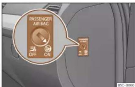
Fig. 15 Switch for activating and deactivating the front passenger airbag.

Fig. 16 On the roof console: control lamp for the deactivation of the front passenger front airbag.
Deactivate the front passenger front airbag only if you have to use a rear-facing child seat in the front passenger seat.
CUPRA recommends fitting the child seat in the rear seat to avoid having to deactivate the front passenger airbag.
When the front passenger airbag is deactivated, this means that only the front passenger front airbag is deactivated. All the other airbags in the vehicle remain activated.
Deactivate and activate the front passenger front airbag
- Switch the ignition off.
- Open the door on the front passenger side.
- Insert the key into the slot of the switch for deactivating the front passenger airbag
Fig. 15. About 3/4 of the key should enter; this is as far as it will go.
- Turn the key gently to change its position to OFF (deactivate) or to ON (activate). If you have difficulty, ensure that you have inserted the key as far as it will go.
- Close the front passenger door.
- When deactivating the airbag, switch the ignition on and check that the control lamp OFF remains lit where it says PASSENGER AIR BAG in the roof console» Fig. 16.
- When reactivating the airbag, check that when the ignition is switched on, the OFF Hz control lamp does not light up and the ON lamp lights up for 60 seconds and then turns off.

WARNING
• The driver of the vehicle is responsible for disabling or switching on the airbag.
• Always switch off the ignition before disabling the front passenger airbag! Failure to do so could result in a fault in the airbag deactivation system.
- Never leave the key in the airbag disabling switch as it could get damaged or enable or disable the airbag during driving.
- If for any reason an airbag is deactivated, reactivate it as soon as possible so that it can fulfil its protective function.
Safety
Knee airbag
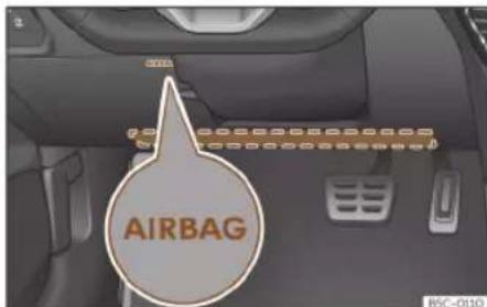
Fig. 17 On the driver side: location of the knee airbag
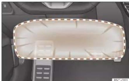
Fig. 18 On the driver side: airbag action radius for the knees.
The knee airbag is located on the driver side below the dash panel>>> Fig. 17. Airbags are identified by the word "AIRBAG".
The framed area (deployment area)
Fig. 18 is covered by the knee airbag when
it is deployed. Objects should never be placed or mounted in this area.
WARNING
• The knee airbag is deployed in front of the driver's knees. Always keep the deployment areas of the knee airbags free.
- Never not fix objects to the cover or in the deployment area of the knee airbag.
- Adjust the driver's seat so that there is a distance of at least 10 cm (4 inches) between your knees and the location of the this airbag. If your physical constitution prevents you from meeting these requirements, make sure you contact a specialised workshop.
Central airbag
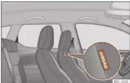
Fig. 19 In the inner padding of the driver's seat backrest: central airbag.
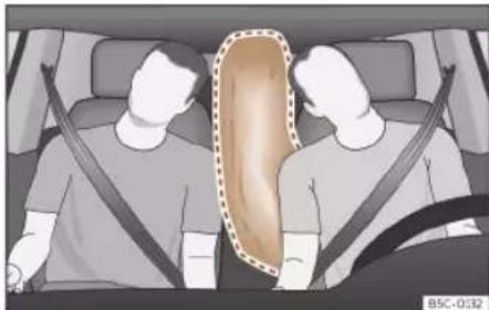
Fig. 20 Fully inflated central airbag (deployment zone).
The central airbag is installed for the front seats and is located in the inner padding of the driver's seat backrest.
The location of the central airbag is indicated by the inscription "AIRBAG">>> Fig. 19.
When triggered, the central airbag fills the marked zone (deployment zone)»» Fig. 20. For this reason, never place or fix objects in this zone»» △
The central airbag triggers in the case of a side collision or if the vehicle overturns, reducing the risk of vehicle occupants suffering injuries.
WARNING
When triggered, the airbag inflates at high speed in milliseconds.
• Always keep the central airbag deployment zone clear.
Airbag system
- Never attach objects to the central airbag cover or the deployment zone.
- Do not allow other people, animals or objects to get between the occupants of the front seats and the airbag deployment zone. Make sure that all vehicle occupants, including children, follow this rule.
- Never use upholstery or seat covers that have not been explicitly authorised for the seats of the vehicle. Otherwise, the side airbag will not be able to deploy if triggered.
WARNING
Improper manipulation of the driver and front passenger seats can prevent the central airbag from operating correctly and cause serious injuries.
- Never remove the front seats from the vehicle or modify their components.
- If the backrest side bolsters are subjected to a lot of force, the central airbag may not trigger correctly, it may not trigger at all or if may trigger unexpectedly.
- Have a specialised repair shop immediately repair any damage to the original seat upholstery or seams in the area of the central airbag module.
Side airbags

Fig. 21 Side airbag in driver's seat.

Fig. 22 Illustration of completely inflated side airbags on the left side of the vehicle.
The side airbags are located in the backrests of the front seats and in the sides of the rear seat, depending on the vehicle's configuration>>> Fig. 21,>>> Fig. 22.
Its location is marked with the word "AIR-BAG" on the upper part of the back of the seats or on the lower coverings with the word AIRBAG in relief.
In conjunction with the seat belts, the side airbag system provides additional protection for the upper body in the event of a severe side collision >> △.
In a side collision, the side airbags reduce the risk of injury to passengers to the areas of the body facing the impact. In addition to their normal protection, the seat belts also hold the passengers in the event of a side collision; this is how these airbags provide maximum protection.
WARNING
- If you do not wear a seat belt, if you lean forward, or are not seated correctly while the vehicle is in motion, you are at a greater risk of injury if the side airbag system is triggered in an accident.
- In order for the side airbags to provide their maximum protection, the prescribed sitting position must always be maintained with seat belts fastened while travelling.
- In a side-on collision the side airbags will not work if the sensors do not correctly measure the pressure increase on the interior of the doors, due to air escaping through the areas with holes or openings in the door panel.
Safety
- Never drive if the interior door panels have been removed or if the panels have not been correctly fitted.
- Never drive the vehicle if the loudspeakers in the door panels have been removed, unless the holes left by the loudspeakers have been closed properly.
• Always check that the openings are closed or covered if loudspeakers or other equipment are fitted inside the door panels. - Occupants of the outer seats must never carry any objects or pets in the deployment space between them and the airbags, or allow children or other passengers to travel in this position. It is also important not to attach any accessories (such as cup holders) to the doors. This would impair the protection offered by the side airbags.
- The built-in coat hooks should be used only for lightweight clothing. Do not leave any heavy or sharp-edged objects in the pockets.
- Great forces, such as hard blows or kicks, must not be exerted upon the backrest bolster because the system may be damaged. In this case, the side airbags would not be triggered.
- Under no circumstances should protective covers be fitted over seats with side airbags unless the covers have been approved for use in your vehicle. Because the airbag deploys from the side of the backrest, the use of conventional seat covers would ob-
struct the side airbag, seriously reducing the airbag's effectiveness.
• Any damage to the original seat upholstery or around the seams of the side airbag units must be repaired immediately by a specialised workshop.
- The airbags provide protection for just one accident; replace them once they have deployed.
• Any work on the side airbag system or removal and installation of the airbag components for other repairs (such as removal of the front seat) should only be performed by a specialised workshop. Otherwise, faults may occur during the airbag system operation.
Head-protection airbags

Fig. 23 Location of head-protection airbags.
The head-protection airbags are located on both sides in the interior above the doors >> Fig. 23 and are identified with the text "AIRBAG".
In combination with the seat belts, the head-protection airbag system gives the vehicle occupants additional protection for the upper body in the event of a severe side collision or the vehicle overturning»» △
The framed area is covered by the head-protection airbag when it is deployed (deployment area)>>> Fig. 23. Therefore, objects should never be placed or mounted in this area>>> △
In the event of a side collision the head-protection airbag is triggered on the impact side of the vehicle.
The head-protection airbags reduce the risk of injury to passengers in the front and rear side seats facing the impact.
WARNING
• In order for the head-protection airbags to provide their maximum protection, the prescribed sitting position must always be maintained with seat belts fastened while travelling.
- For safety reasons, the head-protection airbag must be disabled in those vehicles fitted with a screen dividing the interior of the vehicle. See your technical service to make this adjustment.
Transporting children safely
- There must be no other persons, animals or objects between the occupants of the outer seats and the deployment space of the head-protection airbags so that the head-protection airbag can deploy completely without restriction and provide the greatest possible protection. Therefore, sun blinds which have not been expressly approved for use in your vehicle may not be attached to the side windows.
- The built-in coat hooks should be used only for lightweight clothing. Do not leave any heavy or sharp-edged objects in the pockets. Please, do not hang the clothes on coat hangers.
- The airbags provide protection for just one accident; replace them once they have deployed.
- Any work on the head-protection airbag system or removal and installation of the airbag components for other repairs (such as removal of the roof lining) should only be performed by a specialised workshop. Otherwise, faults may occur during the airbag system operation.
- The side and head airbags are managed through sensors located in the interior of the front doors. To ensure the correct operation of the side and head-protection airbags neither the doors nor the door panels should be modified in any way (e.g. fitting loudspeakers). If the front door is damaged, the airbag system may not work correctly. All work carried out on the front
door must be done in a specialised work- shop.
Transporting children safely
Child safety
Introduction
For safety reasons, as we have learned from accident statistics, we recommend that children under 12 years of age travel in the rear seats. Depending on their age, height and weight, children travelling in rear seats must use a child seat or a seat belt. For safety reasons, the child seat should be installed in the rear seat, behind the front passenger seat or in the centre back seat.
The physical laws involved and the forces acting in a collision apply also to children >> page 18. But unlike adults, children do not have fully developed muscle and bone structures. This means that children are subject to a greater risk of injury.
To reduce the risk of injuries, children must always use special child restraint systems when travelling in the vehicle.
We recommend the use of child safety products from the Original Accessories Programme, which includes systems for all ages made by "Peke" (not for all countries) (see www.seat.com).
Safety
These systems have been especially designed and approved, complying with the ECE-R44. regulation.
CUPRA recommends securing the child seats shown on the website as described below:
- Child seats in the opposite direction of travel (group O+): ISOFIX and support peg (ROMER BABY SAFE PLUS SHR II + ISOFIX BASE / PEKE GO I-SIZE + I-SIZE BASE).
- Child seats in the direction of travel (group 1): ISOFIX and Top Tether (ROMER DUO PLUS + TOP TETHER / PEKE G1 TRIFIX I-SIZE).
- Child seats directed towards the front of the vehicle (group 2): safety belt and ISOFIX (ROMER BRITAX KIDFIX 2 S).
- Child seats directed towards the front of the vehicle (group 3): safety belt (TAKATA MAXI).
Follow the manufacturer's instructions and observe any statutory requirements when installing and using child seats. Always read and note»» page 33.
We recommend you always carry the manufacturer's Child Seat Instruction Manual together with the on-board documentation.
Child seats group classification
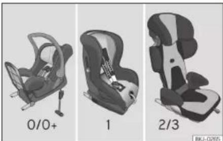
Fig. 24 Examples of child seats.
Use only child seats that are officially approved and suitable for the child.
These seats are subject to the ECE-R44 or ECE-R129 standards. ECE-R stands for: Economic Commission for Europe Regulation.
Child seats by weight group
The child seats are grouped into 5 categories:
| Age group Weight of the child |
| Group 0 Up to 10 kg |
| Group 0+ Up to 13 kg |
| Group 1 From 9 to 18 kg |
| Group 2 From 15 to 25 kg |
| Group 3 From 22 to 36 kg |
Child seats that have been tested and approved under the ECE R44 or ECE-R129 standards bear the ECE-R44 or ECE-R129 test marks on the seat (the letter E in a circle with the test number below it).
Follow the manufacturer's instructions and observe any statutory requirements when installing and using child seats.
We recommend you to always include the manufacturer's Child Seat Instruction Manual together with the on-board documentation.
CUPRA recommends you use child seats from the Original Accessories Catalogue. These child seats have been designed and tested for use in our vehicles. You can find the right child seat for your model and age group at our dealers.
Child seats by approval category
Child seats may have the approval category of universal, semi-universal, vehicle specific (all according to the ECE-R44 standard) or i-Size (according to the ECE-R129 standard).
• Universal: child seats with universal approval can be installed in all vehicles. There is no need to consult any list of models. In the case of universal approval for ISOFIX, the child seat is additionally provided with a Top Tether belt.
- Semi-universal: semi-universal approval, in addition to the standard requirements of
Transporting children safely
universal approval, requires safety devices to lock the child seat, which require additional testing. Child seats with semi-universal approval include a list of vehicle models for which they can be installed.
- Vehicle-specific: vehicle-specific approval requires a dynamic test of the child seat for each vehicle model separately. Child seats with vehicle-specific approval also include a list of vehicle models for which they can be installed.
- i-Size: child seats with i-Size approval must meet the requirements prescribed in the ECE-R 129 standard in relation to installation and safety. Child seat manufacturers can tell you which seats have i-Size approval for this vehicle.
Fitting and using child seats
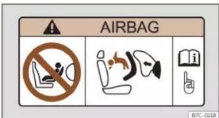
Fig. 25 Airbag sticker: on the passenger's sun visor

Fig. 26 Airbag sticker: on the rear frame of the passenger side door
Warnings about fitting a child seat
Take the following general warnings into account if you are going to fit a child seat. They are valid for all child seats regardless of their attachment system.
- Please read and follow the child seat manufacturer's operating instructions.
• The child seat should preferably be fitted to the rear seat behind the front passenger seat so that the child can exit the vehicle on the pavement side. -
Set the height of the seat belt such that it adapts to the child seat naturally, without twisting. The lowest position of the seat belt height regulator must be used with rear-facing child seats.
-
To correctly use a child seat in the back, the front backrest must be adjusted so that there is no contact with the child seat in the back in the case that it goes opposite to the direction of the car. In the case of front facing restraint systems, the front backrest must be adjusted so that there is no contact with the child's feet.
- For a correct assembly of the child's seat on the rear seats, adjust or dismount the headrest, in order to prevent contact with the seat.
- If a semi-universal type chair is to be installed, in which the method of attachment to the car is through the seat belt and support bracket, it should never be installed in the central rear seat as the ground clearance is lower than in other places and the support bracket will not allow the seat to remain sufficiently stable.
- When fitting a child seat on the front passenger seat, the seat must be moved backwards as far as possible and placed in the »
Safety
highest position. The backrest must also be put in a vertical position 1) .
Important information about the front passenger front airbag
A sticker with important information about the passenger airbag is located on the passenger's sun visor and/or on the passenger side door frame» Fig. 25.
Read and always observe the safety information included in the following chapters:
- Safety distance with respect to the passenger airbag »»page 23.
- Objects between the passenger and the passenger side airbag >> △ in Front airbags on page 27.
The passenger side front airbag, when enabled, is a serious risk for a child that is facing backward since the airbag can strike the seat with such force that it can cause serious or fatal injuries. Children up to 12 years old should always travel on the rear seat.
Therefore we strongly recommend you to transport children on the rear seats. This is the safest location in the vehicle. Alternatively, the front passenger airbag can be dis-
abled with a key-operated switch» page 27. When transporting children, use a child seat suitable for the age and size of each child >> page 32.
WARNING
- If a child seat is secured to the front passenger seat, the risk to the child of sustaining critical or fatal injuries in the event of an accident increases.
- An inflating front passenger airbag can strike the rear-facing child seat and project it with great force against the door, the roof or the backrest.
- Never install a child seat facing backwards on the front passenger seat unless the front passenger front airbag has been disabled. Risk of potentially fatal injuries to the child! However, if necessary, the front passenger front airbag must be deactivated >> page 27. If the passenger seat has a height adjustment option, move it to the highest, most upright position. If you have a fixed seat, do not install any child restraint system in this location.
- For those vehicles that do not include a key lock switch to deactivate the airbag, the vehicle must be taken to a technical service. Do not forget to reconnect the airbag
when an adult wants to sit in the front passenger seat.
- Never allow a child to be transported in a vehicle without being properly secured, or to stand up or kneel on a seat while travelling. In an accident, the child could be flung through the vehicle, causing possibly fatal injuries to themselves and to the other vehicle occupants.
- Never leave a child alone in the child seat or in the vehicle.
• Children who are less than 1.5 metres tall must not wear a normal seat belt without a child seat, as this could cause injuries to the abdominal and neck areas during a sudden braking manoeuvre or in an accident. - When a child seat is mounted in the rear seats, the door child-proof lock should be activated» page 105.
Attachment systems
Depending on the country, different attachment systems are used for safely installing child seats.
Transporting children safely
Attachment systems overview
- ISOFIX: ISOFIX is a standardised attachment system allowing quick and safe attachment of child seats in the vehicle. ISOFIX attachment establishes a rigid connection between the child seat and the car body.
The child seat has two rigid attachment clips, called connectors. These connectors are fitted into the ISOFIX attachment rings found between the seat cushion and the backrest of the vehicle's back seat (on the sides). ISOFIX attachment systems are used mainly in Europe» page 36. If necessary, ISOFIX attachment may have to be supplemented with a Top Tether belt or a support bracket.
- Automatic three-point seat belt. Whenever possible, it is preferable to attach the child seats with the ISOFIX system rather than attaching them with an automatic three-point seat belt >> page 40.
Additional attachment:
- Top Tether: the Top Tether belt is guided over the back of the rear seat and attached to an anchor point with a hook. Anchor points are located at the back of the rear seat backrest on the boot side» page 38 . The rings for retaining the Top Tether belt are marked with an anchor symbol.
- Support bracket: some child seats rest on the floor of the vehicle with a support bracket. The support bracket prevents the child seat from tipping forward in the event of impact. Child seats fitted with a support bracket should only be used in the passenger seat and side rear seats» For the assembly of this type of seat you should also consult the list of approved vehicles for this assembly, available in the instructions for child restraint systems.
Recommended systems for attaching child seats
CUPRA recommends attaching child seats as follows:
- Baby carriers or child seats in the opposite direction of travel: ISOFIX and support bracket or i-Size.
- Child seats in the direction of travel: ISO-FIX and Top Tether.
WARNING
Incorrect use of the support bracket can cause serious or fatal injury.
• Make sure the support bracket is correctly and safely installed.
Safety
Fit a child seat with the ISOFIX / i-Size and Top Tether system

Fig. 27 Rear seat: die cut slots to access the ISOFIX / iSize securing rings.

Fig. 28 Front passenger seat: ISOFIX/i-Size securing rings.
Child seats can be secured quickly, easily and safely on the rear side seats with the "ISOFIX" and Top Tether system.
Two "ISOFIX" retaining rings are fitted on each rear side seat. In some vehicles, the
rings are secured to the seat frame and, in others, they are secured to the rear floor. The "ISOFIX" rings are located between the rear seat backrest and the seat cushioning >> Fig. 27. The Top Tether rings are located on the rear part of the rear seat backrests
(behind the backrest or in the luggage compartment)»» page 38.
To understand the compatibility of the "ISO-FIX" systems in the vehicle, check the table below.
Transporting children safely
Vehicle ISOFIX positions
| Weight group Size class | a) | Electrical equipment | Front passenger seat | Rear side seat Rear central seat | |
| airbag enabled airbag disabled | |||||
| Group 0 to 10 kg E ISO/R1 X IL IL X | |||||
| Group 0+ to 13 kg | E ISO/R1 X IL IL X | ||||
| D ISO/R2 X IL IL X | |||||
| C ISO/R3 X IL IL X | |||||
| D ISO/R2 X IL IL X | |||||
| C ISO/R3 X IL IL X | |||||
| Group I 9 to 18 kg | B ISO/F2 X IL, IUF IL, IUF X | ||||
| B1 ISO/F2X | X IL, IUF IL, IUF X | ||||
| A ISO/F3 X IL, IUF IL, IUF X | |||||
| Group II 15 to 25 kg | B2/B3 | ISO/B2/B3b) | X IL IL X | ||
| Group III 22 to 36 kg B2/B3 | ISO/B2/B3 | b) | X IL IL X | ||
IUF: Suitable for forward-facing ISOFIX universal child restraint systems approved for use in this weight group.
IL: It is suitable for certain ISOFIX child restraint systems (CRS) that can be for the specific vehicle, restricted or semi-universal categories. Take the child seat manufacturer's vehicle list into account.
X: ISOFIX position not suitable for ISOFIX child restraint systems for this weight group or size class.
》
Safety
Vehicle i-Size positions
| Front passenger seat | Rear side seat Rear central seat | ||
| airbag enabled airbag disabled |
Xi-Ui-UX
i-U: Position suitable for forward- or rear-facing i-Size child restraint systems with universal certification.
X: Position not suitable for i-Size child restraint systems.
Securing the child seat with the "ISOFIX/i-Size" system
You must follow the child seat manufacturer's instructions.
- Open the cut-out section behind the marked grooves to access the retaining rings >> Fig. 27.
- Press the child seat onto the "ISO-FIX/iSize" retaining rings until it is heard to engage securely. If the child seat is equipped with Top Tether anchor points, secure it to the correspondent ring» page 38. Follow the child seat manufacturer's instructions.
- Pull on both sides of the child seat to ensure that it is properly anchored.
Child seats with the "ISOFIX" and Top Tether attachment system are available from Technical Services.
WARNING
The securing rings are designed only for use with "ISOFIX" and Top Tether system child seats.
- Never secure other child seats that do not have the "ISOFIX" or Top Tether system, or safety belts or any other objects to the securing rings – as this can result in potentially fatal injuries to the child.
- Ensure that the child seat is correctly secured to the "ISOFIX" and Top Tether securing rings.
Top Tether securing belts


Fig. 29 Rear seats: adjustment and assembly according to the Top Tether belt.
Transporting children safely

Fig. 30 Front passenger seat: adjustment and assembly according to the Top Tether belt.
Child seats with the Top Tether system come with a strap for securing the seat to the vehi-
cle anchor point, located at the back of the rear seat backrest and provide greater restraint.
The objective of this strap is to reduce forward movements of the child seat in a crash, to reduce the risk of injuries to the head from hitting the inside of the vehicle.
Using the Top Tether in rear-facing mounted seats
Currently, there are very few rear-facing child safety seats that have Top Tether. Please carefully read and follow the seat manufacturer instructions to learn the proper way to install the Top Tether strap.
Securing the retainer strap
- Follow the manufacturer's instructions to deploy the child seat Top Tether retaining strap.
-
Position the belt under the headrest (depending on the instructions of the seat itself, lift or remove the headrest if necessary)
Fig. 29[A]/B, >> Fig. 30[A]/B.
-
Slide the strap and secure it properly with the anchorage of the backrest»»Fig. 29 [c], »» Fig. 30 [c].
- Firmly tighten the strap following the manufacturer's instructions.
Releasing the retaining strap
- Loosen the strap following the manufacturer's instructions.
- Push the lock and release it from the anchoring support.
WARNING
An undue installation of the safety seat will increase the risk of injury in the event of a crash.
- Never tie the retainer strap to a hook in the luggage compartment.
- Never secure or tie luggage or other items to the lower anchorages (ISOFIX) or the upper ones (Top Tether).
Safety
Fitting a child seat using the seat belt

Fig. 31 On the rear seats: installing the child seat.
If you want to fit a universal approval category (U) child seat in your vehicle, you must check that the seat is approved for your vehicle. You will find any necessary information on the child seat's orange ECE approval label. The following table shows the different fitting options.
| Weight group | Front passenger seata) | Rear side seat Rear central seat b) | ||
| Airbag enabled airbag disabled c) | ||||
| Group 0 to 10 kg X U U U | ||||
| Group 0+ to 13 kg X U U U | ||||
| Group I 9 to 18 kg X U U U | ||||
| Group II 15 to 25 kg X UF UF UF | ||||
| Group III 22 to 36 kg X UF UF UF | ||||
| X: Not compatible for the installation of seats install chairs in this configuration.U: Suitable for universal restraint systems for use in this weight group.UF: Acceptable for front-facing universal-category child restraint systems approved for this mass group. | ||||
a) Compliance with current national legislation and the manufacturer's instructions is required when using or installing child seats.
b) For semi-universal chairs where the securing system is the car safety belt and the support bracket, do not use them in the centre rear seat.
c) Seats without height adjustment should be placed in their rearmost position. Seats with height adjustment should be placed in their rearmost and highest position.
Transporting children safely
Fitting a child seat using the seat belt
- Set the height of the seat belt such that it adapts to the child seat naturally, without twisting. The lowest position of the seat belt height regulator must be used with rear-facing child seats.
- Put the seat belt in place and pass it through the child seat according to the instructions of the child seat manufacturer.
• Make sure that the seat belt is not twisted. - Insert the latch plate into the seat's buckle until you hear the engagement click.

WARNING
When travelling, children must be secured in the vehicle with a restraint system suitable for age, weight and size.
- Read and always observe information and warnings concerning the use of child seats >> page 33.
Emergencies
Emergencies
Self-help
Information, assistance and emergency call service
How it works

Fig. 32 On the roof console: voice service controls
Depending on the equipment, there is a control on the roof console.
By pressing the buttons i, ✗ and sos >> Fig. 32, you can run the following voice services:
• information call
- assistance call
• emergency call service.
A built-in control unit establishes the connection.
When a voice service is activated, a connection is established with a phone line.
Control lamp
The control has a warning lamp»» Fig. 32 (arrow). It shows the following statuses:
- Off: the eCall service is not available.
- Flashes red, approx. 20 seconds after switching on the ignition: the eCall service is off.
- Lights up red: system failure. The eCall service is available with certain restrictions. CUPRA suggests going to a specialised workshop.
- Lights up green: the eCall service is available. The system works correctly.
- Flashes green: There is an ongoing voice connection.
Information call 1
With the information call, a call is made to SEAT, S.A. customer service.
→ Assistance call 1)
With the assistance call you can directly request specialised help in the event of a breakdown.
Parallel to the voice call, some vehicle data is transmitted, e.g. your current location.
sos Emergency call service 1)
If an emergency call is conducted manually or activated automatically in the event of an accident with an airbag triggering, information relevant to the emergency is broadcast, e.g. the current location of the vehicle >> page 361.
If the call is public, the person on the other end of the line uses the language of the country in which you are located.
If the call is private, the person on the other end of the line will assist you in the language you have configured in the Infotainment system. If the configured language is not available, English will be used.
Diversion to 112 emergency number
In some situations where the emergency call service is limited or cannot be carried out, an emergency call is made to 112.
Self-help
The following conditions may cause the emergency call service to function in a limited manner or the call to be diverted to the 112 emergency number:
- The emergency call is made from an area with weak or no mobile and GPS signal, as well as e.g. tunnels, between very tall buildings, garages, underground walkways, mountains and valleys.
• In areas with sufficient mobile telephone and GPS coverage, the mobile telephone network of the telecommunications operator in question may not be available.
• In some countries, the emergency call service may not be available due to legal reasons. There is no valid license for the use of the emergency call service. - The components of the vehicle required for the emergency phone call are damaged or do not get enough power.
- In some countries, the emergency call service may not be available and depending on the location of the vehicle, the control lamp LEDs, and even the operation of the different types of calls, could have a specific behaviour.
Note
Breakdown service and information calls can incur an additional cost on your telephone bill.
Emergency equipment
Vehicle tool kit

Fig. 33 Underneath the floor panel of the luggage compartment: vehicle tool kit.
The vehicle tool kit is located under the floor panel in the luggage compartment. To access the vehicle tools»»page 136.
The tool kit includes:
① Adapter for the anti-theft bolt
② Towing eye, removable
③ Wheel spanner
④ Crank handle for jack
⑤ Jack
⑥ Hook for extracting the central wheel trims
⑦ Clip for removing the wheel bolt caps
Some of the items listed are only provided in certain model versions, or are optional extras.
WARNING
When the vehicle tool kit, tyre mobility set and spare wheel are loose in the interior they can be violently thrown in case of a sudden manoeuvre or braking and especially in accidents, causing serious injury.
- Ensure that the vehicle tool kit, the tyre mobility set and the spare wheel or temporary spare wheel are safely secured in the luggage compartment.
WARNING
Unsuitable or damaged vehicle tools can cause injury or accidents.
- Never work with inappropriate or damaged tools.
Note
The jack does not generally require any maintenance. If required, it should be greased using universal type grease.
Emergencies
Tyre repairs
TMS (Tyre Mobility System)
The Tyre Mobility System will reliably seal punctures caused by the penetration of a foreign body of up to about 4 mm in diameter. Do not remove foreign objects, e.g. screws or nails, from the tyre.
After inserting the sealant residue in the tyre, you must again check the tyre pressure about 10 minutes after starting the engine.
You should only use the tyre mobility set if the vehicle is parked in a safe place, you are familiar with the procedure and you have the necessary tyre mobility set! Otherwise, you should seek professional assistance.
Do not use the tyre sealant in the following cases:
• If the wheel rim has been damaged.
- In outside temperatures below -20°C (-4°F) .
- In the event of cuts or perforations in the tyre greater than 4 mm.
- If you have been driving with very low pressure or a completely flat tyre.
- If the sealant bottle has passed its use by date.
WARNING
Using the tyre mobility system can be dangerous, especially when filling the tyre at the roadside. Please observe the following rules to minimise the risk of injury:
- Stop the vehicle safely as soon as possible. Park it at a safe distance from surrounding traffic to fill the tyre.
- Ensure the ground on which you park is flat and solid.
- All passengers and particularly children must keep a safe distance from the work area.
- Turn on the hazard warning lights to warn other road users.
- Use the tyre mobility system only if you are familiar with the necessary procedures. Otherwise, you should seek professional assistance.
• The tyre mobility set is intended for temporary emergency use only until you can reach the nearest specialised workshop. - Replace the repaired tyre with the tyre mobility set as soon as possible.
- The sealant is a health hazard and must be cleaned immediately if it comes into contact with the skin.
• Always keep the tyre mobility set out of the reach of small children.
• Always stop the engine, apply the electronic parking brake and put it in gear if fitted with a manual gearbox, or press the
parking lock button P it fitted with an automatic gear box, to reduce the risk of involuntary movement of the vehicle.
WARNING
A tyre filled with sealant does not have the same performance properties as a conventional tyre.
- Never drive faster than 80 km/h (50 mph).
- Avoid heavy acceleration, hard braking and fast cornering.
- Drive for only 10 minutes at a maximum speed of 80 km / h (50 mph) and then check the tyre.
For the sake of the environment
Dispose of used or expired sealant observing any legal requirements.
Note
You can purchase a new bottle of tyre sealant in specialised CUPRA dealers or any SEAT dealership.
Note
Take into account the separate instruction manual of the tyre mobility system's manufacturer.
Self-help
Anti-puncture kit contents

Fig. 34 Standard representation: anti-puncture kit contents.
The anti-puncture kit is located underneath the floor covering in the luggage compartment. It includes the following components >> Fig. 34:
① Valve insert remover
② A sticker to be adhered to the instrument cluster, within the driver's visual field, to remind that the maximum advisable speed "max. 80 km/h" or "max. 50 mph"
③ Filler tube with cap
④ Air compressor (depending on the version, the model may vary).
⑤ ON/OFF switch
⑥ Air bleed screw (it can also be integrated in the inflator tube).
⑦ Warning provided by tyre pressure monitoring system (it can also be integrated in the inflator tube).
⑧ Tube for inflating tyres
⑨ 12 volt connector
10 Bottle of sealant
⑪ Spare tyre valve
The valve insert remover ① has a gap at the lower end for a valve insert. The valve insert can only be screwed or unscrewed in this way. This also applies to its replacement part ② .
Sealing and inflating a tyre
Sealing the tyre
- Unscrew the tyre valve cap and insert. Use the >>Fig. 34 ① tool to remove the insert. Place it on a clean surface.
- Shake the tyre sealant bottle vigorously >> Fig. 34 10.
- Screw the inflator tube»» Fig. 34 ③ into the sealant bottle. The bottle's seal will break automatically.
-
Remove the lid from the filling tube
Fig. 34 ③ and screw the open end of the tube into the tyre valve.
-
With the bottle upside down, empty all of the contents into the tyre.
- Remove the bottle from the valve.
- Place the insert back into the tyre valve using the tool>> Fig. 34 ①.
Inflating the tyre
- Screw the compressor tyre inflator tube >> Fig. 34 ⑧ into the tyre valve.
- Check that the air bleed screw is closed
Fig. 34 ⑥
- Start the engine and leave it running.
- Insert the connector>>Fig. 34 ⑨ into the vehicle's 12-volt socket» page 145.
- Turn the air compressor on with the ON/OFF switch>> Fig. 34 ⑤.
- Keep the air compressor running until it reaches 2.0 to 2.5 bar (29-36 psi/200-250 kPa). A maximum of 8 minutes.
- Disconnect the air compressor.
- If it does not reach the pressure indicated, unscrew the tyre inflator tube from the valve.
- Move the vehicle 10m so that the sealant is distributed throughout the tyre.
- Screw the compressor tyre inflator into the valve.
- Repeat the inflation process.
- If the indicated pressure still cannot be reached, the tyre is too badly damaged. Stop »
Emergencies
and request assistance from an authorised technician.
- Disconnect the air compressor. Unscrew the tyre inflator tube from the tyre valve.
- When the tyre pressure is between 2.5 and 2.0 bars, continue driving without exceeding 80 km / h (50 mph).
- Attach the sticker>> Fig. 34 ② to the instrument cluster, within the driver's visual field.
- Check the pressure again after 10 minutes
page 46.
WARNING
When inflating the wheel, the air compressor and the inflator tube may become hot.
- Protect hands and skin from hot parts.
- Do not place the hot flexible inflator tube or hot air compressor on flammable material.
- Allow them to cool before storing the device.
- If it is not possible to inflate the tyre to at least 2.0 bars (29 psi / 200 kPa), the tyre is too badly damaged. The sealant is not in a good condition to seal the tyre. Do not continue driving. Seek specialist assistance.
CAUTION
Switch off the air compressor after a maximum of 8 operational minutes to avoid
overheating! Before switching on the air compressor again, let it cool for several minutes.
Check after 10 minutes of driving
Screw the inflator tube>>Fig. 34 ⑤ again and check the pressure on the gauge ⑥.
1.3 bar (19 psi / 130 kPa) and lower:
- Stop the vehicle! The tyre cannot be sealed sufficiently with the tyre mobility set.
- You should obtain professional assistance >>> ▲.
1.4 bar (20 psi / 140 kPa) and higher:
- Set the tyre pressure to the correct value again.
- Carefully resume your journey until you reach the nearest specialised workshop without exceeding 80 km/h (50 mph).
• Have the damaged tyre replaced.
WARNING
Driving with an unsealed tyre is dangerous and can cause accidents and serious injury.
- Do not continue driving if the tyre pressure is 1.3 bar (19 psi / 130 kPa) and lower.
- Seek specialist assistance.
Changing a wheel
What to do first
- Park the vehicle on a horizontal surface and in a safe place as far away from traffic as possible.
- Apply the electronic parking brake.
- Switch on the hazard warning lights.
• Manual transmission: engage 1st gear. - Automatic transmission: switch on the parking lock by pressing button P.
- If you are towing a trailer, unhitch it from your vehicle.
- Make sure that the vehicle tool kit >> page 43 and the spare wheel >> page 347 are ready.
- Observe the applicable legislation for each country (reflective vest, warning triangles, etc.).
- All occupants should leave the vehicle and wait in a safe place (for instance behind the roadside crash barrier).
WARNING
• Always observe the above steps and protect yourself and other road users.
- If you change the wheel on a slope, block the wheel on the opposite side of the car with a stone or similar to prevent the vehicle from moving.
Self-help
Wheel bolt caps

Fig. 35 Wheel: wheel nuts with caps.
Removal
- Fit the plastic clip (vehicle tools) Fig. 33) over the cap until it clicks into place
Fig. 35.
- Remove the cap with the plastic clip.
The caps protect the wheel nuts and should be remounted after changing the tyre.
The anti-theft wheel locking bolt has a special cap. This only fits on anti-theft locking bolts and is not for use with standard wheel nuts.
Anti-theft wheel nuts
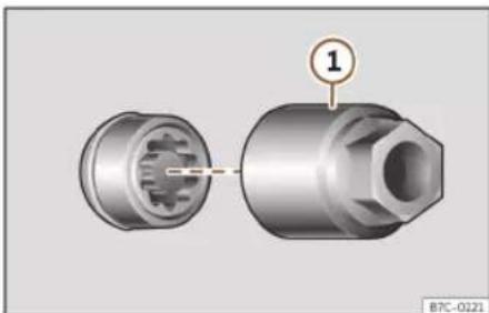
Fig. 36 Anti-theft wheel bolt with cap and adapter.
Loosening the anti-theft wheel bolt
- Remove the wheel cover or the cap.
- Insert the special adapter>> Fig. 36 ① (vehicle tools>> page 43) onto the anti-theft wheel bolt and push it on as far as it will go.
- Insert the wheel brace (vehicle tools) onto the adapter as far as it will go.
- Remove the wheel bolt»» page 47.
Note
Make a note of the code number of the anti-theft wheel bolt and keep it in a safe place, but not in your vehicle. If you need a new adapter, you can obtain it from the specialised CUPRA service or the SEAT Official Service, indicating the code number.
Loosening wheel nuts

Fig. 37 Wheel change: loosen the wheel nuts.
Use only the wheel wrench belonging to the car to loosen the wheel nuts.
Loosen the wheel nuts only about one turn before raising the vehicle with the jack.
If the wheel bolt is very tight, carefully push on the end of the wheel wrench with your foot. Hold on to the vehicle for support and take care not to slip during this operation.
Loosening wheel nuts
- Fit the wheel wrench on as far as it will go >> Fig. 37.
- Hold the wrench at the end and rotate the bolt approximately one turn anticlockwise >> △
Emergencies
Important information about wheel nuts
Factory-fitted rims and wheel nuts are specially matched during construction. Therefore, if different rims are fitted, the correct wheel nuts with the right length and heads must be used. This ensures that wheels are fitted securely and that the brake system functions correctly.
In certain circumstances, you should not even use wheel nuts from vehicles of the same model.
WARNING
If the wheel nuts are not properly tightened, they could come loose while driving and cause an accident, serious injury and loss of vehicle control.
- Use only wheel nuts which correspond to the rim in question.
- Never use different wheel nuts.
- Wheel nuts and threads should be clean, free of oil and grease, and it should be possible to screw them easily.
• To loosen and tighten wheel nuts, only use the wheel wrench that came with the car from the factory. - The wheel nuts should only be loosened slightly (about one turn) before raising the vehicle with the jack. Risk of accident!
- Never apply grease or oil to wheel nuts or to the wheel hub threads. Even if the bolts
have been tightened to the prescribed torque, they could come loose while driving.
- Never loosen the screwed joints of wheel rims with bolted ring trims.
- If wheel nuts are tightened below the prescribed torque, the bolts and rims could come loose while driving. If tightening torque is too high, the wheel nuts or threads can be damaged.
Raise the vehicle

Fig. 38 Jack position points.

Fig. 39 Cross member: positioning the jack on the vehicle.
- Rest the jack (vehicles tools) on firm ground. If necessary use a large, strong board or similar support. If the surface is slippery (for example tiles) place the jack on a rubber mat or similar to prevent it from slipping >> △
- Find the support point on the strut (sunken area) closest to the wheel to be changed
Fig. 38.
- Turn the jack crank handle, located below the strut support point, to raise it until the tab ①>>>Fig. 39 is below the housing provided.
- Align the jack so that tab ① "grips" onto the housing provided on the strut and the mobile base ② is resting on the ground. The base plate ② should fall vertically with respect to the support point ①.
- Continue turning the jack until the wheel is slightly lifted off the ground.
Self-help

WARNING
The factory-supplied jack is only designed for changing wheels on this model. On no account attempt to use it for lifting heavier vehicles or other loads. Risk of injury.
- Make sure the jack remains stable. If the surface is slippery or soft, the jack could slip or sink, respectively, with the consequent risk of causing injuries.
- Lift the vehicle using only the jack supplied from the factory. Other jacks, even those approved for other CUPRA models could slip, with the consequent risk of injury.
- Place the jack only at the support points provided on the strut and align it. Otherwise, the jack could slip because it does not have sufficient grip on the vehicle: risk of injury!
- You should never place a body limb such as an arm or leg under a raised vehicle that is solely supported by the jack.
- If you have to work underneath the vehicle, you must use suitable stands additionally to support the vehicle, there is a risk of accident!.
- Never raise the vehicle if it is tilting to one side or the engine is running.
- Never start the engine when the vehicle is raised. The vehicle may come loose from the jack due to the engine vibrations.

CAUTION
The vehicle must not be raised on the crossbar. Place the jack only at the support points provided on the strut and align it. Otherwise, the vehicle may be damaged.
Removing and installing a wheel
Change the wheel after loosening the wheel nuts and raising the vehicle with the jack.
When removing/fitting the wheel, the rim may hit and damage the brake disc. For this reason, please take care and get a second person to assist you.
Taking off the wheel
- Unscrew the wheel nuts using the box spanner and place them on a clean surface.
• Take off the wheel.
Putting on the spare wheel
Check the direction of rotation of the tyre >> page 50.
- Place the spare wheel or temporary spare wheel into position.
- Screw on the wheel nuts in position and tighten them loosely with a box spanner.
-
To tighten the anti-theft locking wheel nuts use the corresponding adaptor.
-
Carefully lower the vehicle using the jack.
- Use the wheel spanner to tighten all of the wheel nuts clockwise. Tighten the bolts in diagonal pairs (not in a circle).
- Put the caps, trim or full hubcap back on.
The wheel nuts should be clean and turn easily. Before fitting the spare wheel, inspect the wheel condition and hub mounting surfaces. These surfaces must be clean before fitting the wheel.
Tightening torque of the wheel nuts
The prescribed tightening torque for wheel nuts for steel and alloy wheels is 140 Nm. After changing a wheel, have the tightening torque checked immediately with a torque wrench that is working perfectly.
Before checking tightening torque, have any rusty wheel nuts that are difficult to screw replaced and clean the wheel hub threads.
Never apply grease or oil to wheel nuts or to the wheel hub threads. Even if the bolts have been tightened to the prescribed torque, they could come loose while driving.
Emergencies
Tyres with directional tread pattern
Tyres with directional tread pattern have been designed to operate best when rotating in only one direction. An arrow on the tyre sidewall indicates the direction of rotation on tyres with directional tread. Always observe the indicated direction of rotation in order to guarantee optimum grip and help avoid aquaplaning, excessive noise and wear.
If the tyre is mounted in the opposite direction of rotation, drive with extreme caution, as the tyre is no longer being used correctly. This is of particular importance when the road surface is wet. Change the tyre as soon as possible or remount it with the correct direction of rotation.
Works after changing a wheel
- Replace the wheel bolt caps.
- Return all tools to their proper storing location.
- If the replaced wheel does not fit in the spare wheel housing, store it safely in the luggage compartment >> page 134.
-
Check the tyre pressure of the newly mounted tyre as soon as possible.
-
In vehicles fitted with a tyre pressure indicator, adjust the pressure and store it in memory»» page 346.
- Have the tightening torque of the wheel nuts checked as soon as possible with a torque wrench»»page 49. Meanwhile, drive carefully.
- Have the flat tyre replaced as quickly as possible.
Changing the windscreen wiper blades
Wiper service position

Fig. 40 Wipers in service position.
Ensure that the wiper blades are not frozen. The wiper arms can be raised when the wipers are in service position>> Fig. 40.
- Close the bonnet»» page 322.
- Switch the ignition on and off.
- Press the windscreen wiper lever downwards briefly»» page 123 4.
Before driving, always lower the wiper arms. Using the windscreen wiper lever, the windscreen wiper arms return to their initial position.
Note
- The windscreen wiper arms can be moved to the service position only when the bonnet is properly closed.
- You can also use the service position, for example, if you want to fix a cover over the windscreen in the winter to keep it clear of ice.
Self-help
Changing the wiper rear wiper blades

Fig. 41 Changing the windscreen wiper blades
The windscreen wiper blades are supplied as standard with a layer of graphite. This layer is responsible for ensuring that the wipe is silent. If the graphite layer is damaged, the noise of the water as it is wiped across the windscreen will be louder.
Check the condition of the wiper blades regularly. If the wipers scrape across the glass, they should be changed if they are damaged, or cleaned if they are dirty >> ①.
If this does not produce the desired results, the setting angle of the windscreen wiper arms might be incorrect. They should be checked by a specialised workshop and corrected if necessary.
Damaged windscreen wiper blades should be replaced immediately. These are available from qualified workshops.
Raising and lowering windscreen wiper arms
- Place the windscreen wipers in the service position»» page 50.
- Grip the wiper arms only by the blade's fastening point.
Cleaning windscreen wiper blades
- Raise the wiper arms.
- Use a soft cloth to remove dust and dirt from the windscreen wiper blades.
- If the blades are very dirty, a sponge or damp cloth may be used>>>
Changing the windscreen wiper blades
- Lift and unfold the wiper arms.
- Press and hold release button>> Fig. 41 ① and pull gently on the wiper blade in the direction of the arrow.
- Fit a new wiper blade of the same length and design on to the wiper arm and hook it into place.
- Rest the wiper arms back onto the wind-screen.
Changing the rear window wiper blade
- Separate the wiper arm from the rear window.
- Remove the blade from the holder below the centre. During this operation, hold the wiper arm firmly.
- Fit the new blade (of the same length and type) into the housing of the wipe arm by pressing it in place. When doing so, hold the wiper arm by the upper end.
- Fold the wiper arm and rest it on the window.

WARNING
Worn or dirty windscreen wiper blades reduce visibility and increase the risk of accident and serious injury.
• Always replace damaged or worn wind-screen wiper blades or blades that no longer clean the windscreen properly.

CAUTION
- Damaged or dirty windscreen wipers could scratch the glass.
- If products containing solvents, rough sponges or sharp objects are used to clean the blades, the graphite layer will be damaged.
- Never use fuel, nail varnish remover, paint thinner or similar products to clean the windows.
Emergencies
- In icy conditions, always check that the wiper blades are not frozen to the glass before using the wipers. In cold weather, it may help to leave the vehicle parked with the wipers in service position >> page 50.

CAUTION
• To prevent damage to the bonnet and the wiper arms, only leave them in the service position.
- Before driving, always lower the wiper arms.
Jump start
Jump leads
The jump lead must have a sufficient wire cross section.
If the engine fails to start because of a discharged battery, the battery can be connected to the battery of another vehicle to start the engine.
Jump leads must comply with standard DIN 72553 (see cable manufacturer's instructions). The wire cross section must be at least 25mm2 for petrol engines and at least 35mm2 for diesel engines.

Note
• The vehicles must not touch each other, otherwise electricity could flow as soon as the positive terminals are connected.
- The discharged battery must be properly connected to the on-board network.
Jump start: description
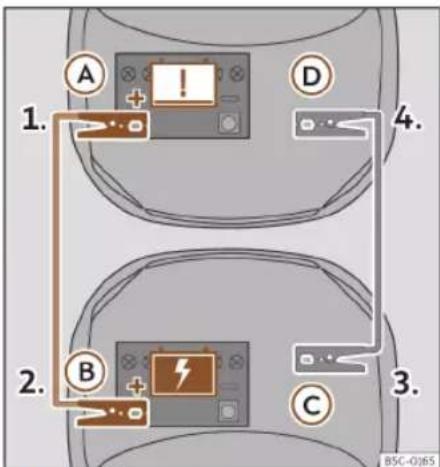
Fig. 42 Diagram of connections for vehicles with Start-Stop system.
Jump lead terminal connections
-
Switch off the ignition of both vehicles >>> △.
-
Connect one end of the red jump lead to the positive ⊕ terminal of the vehicle with the flat battery A.
- Connect the other end of the red jump lead to the positive terminal + in the vehicle providing assistance (B)
- Connect one end of the black jump lead © to a suitable ground terminal, to a solid piece of metal in the engine block, or to the engine block itself.
- Connect the other end of the black jump lead D to a solid metal component bolted to the engine block or to the engine block itself of the vehicle with the flat battery. Do not connect it to a point near the battery.
- Position the leads in such a way that they cannot come into contact with any moving parts in the engine compartment.
Starting
- Start the engine of the vehicle with the boosting battery and let it run at idling speed.
- Start the engine of the vehicle with the flat battery and wait for 2 or 3 minutes until the engine is running.
Self-help
Removing the jump leads
- Before you remove the jump leads, switch off the dipped beam headlights if they are switched on.
- Turn on the heater blower and heated rear window in the vehicle with the flat battery. This helps minimise voltage peaks which are generated when the leads are disconnected.
- When the engine is running, disconnect the leads in reverse order to the details given above.
Make sure the battery clamps have sufficient metal-to-metal contact with the battery terminals.
If the engine fails to start after about 10 seconds, switch off the starter and try again after about 1 minute.

WARNING
- Please note the safety warnings referring to working in the engine compartment >> page 322.
- The battery providing assistance must have the same voltage as the flat battery (12V) and approximately the same capacity (see imprint on battery). Failure to comply could result in an explosion.
- Never use jump leads when one of the batteries is frozen. Danger of explosion! Even after the battery has thawed, battery
acid could leak and cause chemical burns. If a battery freezes, it should be replaced.
- Keep sparks, flames and lighted cigarettes away from batteries, danger of explosion. Failure to comply could result in an explosion.
- Observe the instructions provided by the manufacturer of the jump leads.
- Do not connect the negative cable from the other vehicle directly to the negative terminal of the flat battery. The gas emitted from the battery could be ignited by sparks. Danger of explosion.
- Never attach the negative cable to fuel system components or the brake lines in the other vehicle.
- The non-insulated parts of the battery clamps must not be allowed to touch. The jump lead attached to the positive battery terminal must not touch metal parts of the vehicle, this can cause a short circuit.
- Position the leads in such a way that they cannot come into contact with any moving parts in the engine compartment.
- Do not lean on the batteries. This could result in chemical burns.
Note
The vehicles must not touch each other, otherwise electricity could flow as soon as the positive terminals are connected.
Tow start and towing
Introduction
Tow-starting means starting the engine of the vehicle while another pulls it.
Towing means one vehicle pulling another that is not roadworthy.
Always consider the legal provisions relating to tow-starting and towing.
For technical reasons, towing a vehicle with a discharged battery is not allowed. The jump start should be used instead >> page 52.
If the vehicle comes with the Keyless Access system, towing is only allowed with the ignition on!
The vehicle battery drains if the vehicle is towed with the engine switched off and the ignition connected. Depending on the battery charge status, the drop in voltage may be so large, even after just a few minutes, that no electrical device in the vehicle may work e.g. the hazard warning lights. In vehicles with the Keyless Access system, the steering wheel could lock»»
WARNING
A vehicle with no power should never be towed.
»
Emergencies
- During towing, never switch off the ignition using the start button. Otherwise, the electronic lock of the steering column could suddenly become blocked and it would be impossible to steer the vehicle. This could cause an accident, serious injury and loss of control of the vehicle.
- If during towing the vehicle runs out of power, stop towing immediately and request the assistance of specialist personnel.
WARNING
Vehicle handling and braking capacity change considerably during towing. Please observe the following instructions to minimise the risk of serious accidents and injury:
• As the driver of the vehicle being towed:
- You should depress the brake much harder as the brake servo does not operate. Pay the utmost attention to avoid crashing into the towing vehicle.
- More strength is required at the steering wheel as the power steering does not operate when the engine is switched off.
- As the driver of the towing vehicle:
- Accelerate with particular care and caution.
- Avoid sudden braking and manoeuvres.
- Brake earlier than usual and more smoothly.
CAUTION
- To avoid damaging the vehicle, for example the paint, remove and replace the lid and towing eye carefully.
- Unburnt fuel could enter the catalytic converter and damage it during towing.
Instructions for tow-starting
Vehicle's should not generally be tow-started. The jump start should be used instead >> page 52.
For technical reasons, towing the following vehicles is not allowed:
• Vehicles with an automatic gearbox.
- If the vehicle battery is discharged, because in vehicles with the Keyless Access locking and ignition system the steering remains locked and the electronic parking brake cannot be deactivated nor can the electronic lock of the steering column be released if they are activated.
- If the battery is flat, it is possible that the engine control units may not operate correctly.
If despite everything it is necessary to tow start the vehicle (only if fitted with a manual gearbox):
- Engage 2nd or 3rd gear.
- Keep the clutch depressed.
- Switch on the ignition and the hazard warning lights of both vehicles.
- When both vehicles are in motion, release the clutch.
- As soon as the engine starts, depress the clutch and disengage the gear to avoid colliding with the towing vehicle.
CAUTION
- When tow-starting, unburnt fuel could enter the catalytic converter and damage it.
- The distance to be towed to start the engine must not exceed 50m , otherwise there is a risk of damaging the catalytic converter.
Note
The vehicle can only be jump-started if the electronic parking brake and, if appropriate, the electronic lock of the steering column are deactivated. If the vehicle has no power supply or there is an electric system fault, the engine must be jump-started to deactivate the electronic parking brake and the electronic lock of the steering column.
Self-help
Towing instructions
Towing requires some expertise and experience, especially when using a tow rope. Both drivers should be familiar with the difficulties involved in towing. For this reason, inexperienced drivers should abstain from towing.
During towing, it should be ensured that no impermissible tractive forces or shocks are generated. When towing on an unpaved road, there is always a risk of overloading and damaging the anchorage points.
During towing, the towing vehicle can signal the change of direction even with the hazard warning lights turned on. To do so, at the same time, the turn signal lever must be operated with ignition switched on. Meanwhile, the hazard warning lights will go off. When the turn signal lever is returned to the rest position, the hazard warning lights will be automatically reactivated.
Notes for the driver of the towed vehicle
- Leave the ignition on, so that the steering is not blocked, and the electronic parking brake may be deactivated and the turn signals and wash/wipe operated.
-
More strength is required at the steering wheel as the power steering does not operate when the engine is switched off.
-
You should depress the brake much harder as the brake servo does not operate. Avoid hitting the towing vehicle.
- Bear in mind the information and instructions in the manual of the vehicle to be towed.
Notes for the driver of the towing vehicle
- Accelerate with particular care and caution. Avoid sharp manoeuvres.
- Brake earlier than usual and smoothly.
- Bear in mind the information and instructions in the manual of the towed vehicle.
Tow rope or tow bar
It is safer for the vehicle to be towed using a tow bar, avoiding damage to the vehicle. A tow rope should only be used if a tow bar is not available.
A tow rope should be slightly elastic to avoid damage to both vehicles. It is advisable to use a tow rope made of synthetic fibre or similarly elastic material.
Only attach the tow rope or the tow bar to the towing eyes provided or a towing bracket.
If the vehicle has a factory-fitted towing device, towing with a tow bar is only permitted if it has been specially designed to be installed on a tow hitch» page 291.
When the vehicle has to be towed:
Check whether the vehicle may be towed >> page 56, Cases where towing the vehicle is not permitted.
The vehicle can be towed using a tow bar or tow rope in the normal way, with all four wheels on the road; it can also be towed with either the front or rear wheels lifted off the road.
- Switch the ignition on.
- Move the selector lever to the N >> page 218 position.
- Do not allow the vehicle to be towed at speeds of over 50 km/h (30 mph).
- The vehicle must not be towed further than 50 km (30 miles).
- If a breakdown lorry is used, vehicles with automatic transmission are only allowed to be towed with the front wheels suspended.
Towing vehicles with four-wheel drive (4Drive)
Four-wheel drive vehicles (4Drive) can be towed using a tow bar or tow rope. If the vehicle is towed with the front or rear axle suspended, the engine must be switched off, otherwise the transmission may be damaged.
»
Emergencies
Cases where towing the vehicle is not per- mitted
- If, due to a fault, the gearbox is out of lubricant.
- If the vehicle battery is discharged, because the steering remains locked and, if appropriate, the electronic parking brake cannot be deactivated or the electronic lock of the steering column released.
- If a distance above 50 km needs to be travelled.
- When, for example, after an accident, the smooth rotation of the wheels or the steering operation cannot be guaranteed.
When the vehicle is to tow another vehicle:
- Observe legal requirements.
- Keep in mind the instructions in the manual on towing vehicles.
CAUTION
If there is no oil in the gearbox or no lubricant in the automatic transmission the car may only be towed with the driven wheels lifted clear of the road, or transported on a special car transporter or trailer.
Note
The vehicle can only be towed if the electronic parking brake and the electronic
lock of the steering column are deactivated. If the vehicle has no power supply or there is an electric system fault, the engine must be jump-started» page 52 to deactivate the electronic parking brake and the electronic lock of the steering column.
Front towline anchorage
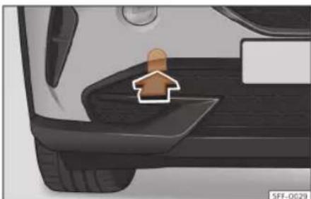
Fig. 43 On the right side of the front bumper: remove the cover.

Fig. 44 Right side of the front bumper: towline anchorage in position.
The housing of the screw towing eye is on the right side of the front bumper behind a lid>>> Fig. 43.
The towing eye should always be kept in the vehicle.
Bear in mind the instructions for towing >>>page 55.
Fitting the towline anchorage
- Remove the towing eye from the vehicle tool kit in the luggage compartment >>page 43.
- Remove the cover by pressing down on its base and leave it hanging from the vehicle >>Fig. 43.
- Screw the towing eye in the housing by turning it as far as it will go anticlockwise>>> Fig. 44 >>> ① Use a suitable object
Self-help
that can completely and securely tighten the towing eye in its housing.
• After towing, unscrew the towing eye clockwise with a suitable object.
- Replace the cover and tighten on its right side until the tab snaps into the bumper.
- Clean the towing eye if necessary and then store it in the luggage compartment along with the other vehicle tools.

CAUTION
The towing eye must always be completely and firmly tightened. Otherwise, it could be released while towing and tow-starting.
Rear towline anchorage

Fig. 45 On the right side of the rear bumper: remove the cover.

Fig. 46 On the right side of the rear bumper: towline anchorage in position.
The housing of the screw towing eye is on the right side of the rear bumper behind a lid >> Fig. 45.
Vehicles equipped as standard with a towing bracket do not have any housing for the screw towing eye behind the lid. In this case, the tow hitch needs to be extracted or installed and used for towing» page 291, >> 0.
Bear in mind the instructions for towing >> page 55.
Assemble the rear towing eye (cars without a factory-equipped towing bracket)
- Remove the towing eye from the vehicle tool kit in the luggage compartment >> page 43.
-
Press the upper side of the lid»» Fig. 45 to unclip it.
-
Remove the lid and let it hang from the vehicle.
- Screw the towing eye in the housing by turning it to the maximum anticlockwise >> Fig. 46 >> 1. Use a suitable object that can completely and securely tighten the towing eye in its housing.
• After towing, unscrew the towing eye clockwise with a suitable object. - Replace the cover and press until the tab snaps into the bumper.
- Clean the towing eye if necessary and then store it in the luggage compartment along with the other vehicle tools.

CAUTION
- The towing eye must always be completely and firmly tightened. Otherwise, it could be released while towing and tow-starting.
- If the vehicle is factory-equipped with a towing bracket, it is only allowed to tow with a tow bar if this has been specially designed to be installed with a tow hitch. If an unsuitable tow bar is used, both the tow hitch and the vehicle may be damaged. Instead, a tow rope should be used.
Emergencies
Fuses and bulbs
Fuses
Introduction
In general, a fuse can be assigned to various electrical components. Likewise, an electrical component can be protected by several fuses.
Only replace fuses when the cause of the problem has been solved. If a newly inserted fuse blows after a short time, you must have the electrical system checked by a specialised workshop as soon as possible.

WARNING
The high voltages in the electrical system can give serious electrical shocks, causing burns and even death!
- Never touch the electrical wiring of the ignition system.
• Take care not to cause short circuits in the electrical system.

WARNING
Using unsuitable fuses, repairing fuses or bridging a current circuit without fuses can cause a fire and serious injury.
- Never use a fuse with a higher value. Only replace fuses with a fuse of the same am-
perage (same colour and markings) and size.
- Never replace a fuse by a metal strip, staple or similar.
CAUTION
- To prevent damage to the vehicle's electrical system, before replacing a fuse always turn off the ignition, the lights and all electrical elements.
- Protect the fuse boxes when open to prevent the entry of dust or humidity as they can damage the electrical system.
Note
• One component may have more than one fuse.
- Several components may run on a single fuse.
- In the vehicle, there are more fuses than those indicated in this chapter.
Fuses inside the vehicle
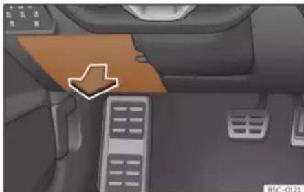
Fig. 47 On the driver's side dashboard: fuse box cover.
Opening and closing the fuse box situated below the dash panel
- Open: fold the cover down>>Fig. 47.
- Close: push back the cover it in until it clicks into place.
Identifying fuses below the dashboard by colours
| Colour Amp rating | |
| Light brown 5 | |
| Brown 7.5 | |
| Red 10 | |
| Blue 15 | |
| Yellow 20 | |
Fuses and bulbs
Colour Amp rating
| White or transparent 25 | |
| Green 30 | |
| Orange 40 | |
CAUTION
- Always carefully remove the fuse box covers and refit them correctly to avoid problems with your vehicle.
- Protect the fuse boxes when open to avoid the entry of dust or humidity. Dirt and humidity inside fuse boxes can cause damage to the electrical system.
Fuses in the engine compartment

Fig. 48 In the engine compartment: fuse box cover.
To open the engine compartment fuse box
- Open the bonnet ⚠>>> page 322.
- Press the locking tabs to release the fuse box cover»» Fig. 48.
- Then lift the cover out.
- To fit the cover, place it on the fuse box. Push the locking tabs down until they click audibly into place.
Replace a blown fuse

Fig. 49 Image of a blown fuse.
Preparations
- Switch off the ignition, lights and all electrical equipment.
- Open the corresponding fuse box >> page 58,>> page 59.
Recognise a blown fuse
A fuse is blown if its metal strip is ruptured >> Fig. 49.
- Point a lamp at the fuse to see if it has blown.
To replace a fuse
- Remove the fuse.
- Replace the blown fuse by one with an identical amperage rating (same colour and markings) and identical size.
- Replace the cover again or close the fuse box lid.
Fuse placement
Fuses in the vehicle interior
| No. | Consumers/Amps | |
| 3 | Trailer 25 | |
| 4 | SCR, Adblue 20 | |
| 5 | Automatic gearbox lever 25 | |
| 6 | Interior light 30 | |
| 8 | Sunroof 20 | |
| 7 | Heated seats | 30 |
| 9 | Left door | 30 |
| 11 | Trailer 15 | |
Emergencies
| No. | Consumers/Amps | |
| 12 | Right lights 40 | |
| 13 | Central locking 40 | |
| 14 | Beats Audio CAN and MOST. 30 | |
| 16 | Airbag 7.5 | |
| 17 | SCR, engine relay, 1.5 10 | |
| 18 | KESSY 7.5 | |
| 19 | Instrument panel 7.5 | |
| 20 | Connectivity Box 7.5 | |
| 21 | Rear camera 7.5 | |
| 24 | 4x4 Haldex Control Unit 15 | |
| 25 | RGS+EBSS front seat belts 25 | |
| 26 | Right door 30 | |
| 27 | RGS+EBSS front seat belts 25 | |
| 28 | PHEV. Switching off the high voltage system for rescue tasks. Identified by a yellow label | 10 |
| 29 | Trailer | 15 |
| 30 | Radio | 30 |
| 31 | Trailer | 25 |
| 34 | 230V socket | 30 |
| 35 | Left lights | 40 |
| 36 | Air conditioner fan | 40 |
| No. | Consumers/Amps | |
| 37 | Electric rear lid | 30 |
| 39 | Heated steering wheel | 10 |
| 40 | Alarm horn | 7.5 |
| 41 | Gateway | 7.5 |
| 42 | Automatic gearbox lever | 7.5 |
| 43 | Air conditioning and heating control panel, rear window heating, AA compressor | 10 |
| 44 | Diagnosis, handbrake switch, light switch, reverse light, interior lighting, lit-up door sill | 7.5 |
| 45 | Steering column | 7.5 |
| 46 | Radio display | 7.5 |
| 47 | Driving mode. | 10 |
| 48 | USB | 7.5 |
| 52 | 12V socket | 20 |
| 58 | Parking sensors, park distance control unit, front camera, radar | 7.5 |
| 59 | Reverse switch, clima sensor, electrochromic mirror | 7.5 |
| 60 | Diagnosis, headlight control unit, headlight adjuster | 7.5 |
| 61 | Starter motor; clutch sensor | 7.5 |
| 65 | Sound amplifier | 10 |
| No. | Consumers/Amps | |
| 66 | Rear window wiper | 15 |
| 67 | Heated rear window | 30 |
| In-line fuse/Amps | ||
| 230 V rear power sockets | 30 | |
| Electric driver's seat 15 | ||
Fuse arrangement in engine compartment
| No. | Consumers/Amps | |
| 2 | Engine control unit | 7.5 |
| 3 | Fuel pump control unit, CNG | 7.5/10/20 |
| Version VZ5: Ignition coils | 30 | |
| 4 | Left headlight | 15 |
| 5 | Right headlight | 15 |
| 7 | Automatic gearbox pump | 30 |
| 8 | Brake servo | 40 |
| 9 | Horn | 15 |
| 10 | Front windscreen washer | 30 |
| 11 | PHEV Climate | 7.5 |
| 12 | Automatic gearbox control unit | 15/30 |
| Version VZ5: Automatic gearbox control unit | 10 | |
| 13 | ESP control unit | 25 |
Fuses and bulbs
| No. | Consumers/Amps | |
| 14 | Standheizung 20 | |
| 15 | ESP control unit 40 | |
| 16 | PHEV, Automatic gearbox unit | |
| 17 | PTC 40 | |
| 18 | PTC 40 | |
| 20 | Front electronic differential 15 | |
| 21 | Engine control unit 7.5 | |
| 22 | Starter motor 30 | |
| 23 | Engine control unit (diesel/petrol) | 15 |
| 24 | Engine sensors 7.5/10 | |
| Version VZ5: Engine relay, electric fan | 7.5 | |
| 25 | Engine sensors 7.5/10 | |
| Version VZ5: Engine sensors 15 | ||
| 26 | Engine power supply 7.5/10 | |
| Version VZ5: Engine power supply | 7.5 | |
| 27 | Lambda probe | 10/15 |
| 28 | Engine | 10/20 |
| 29 | Fuel pump control unit | 15/20/30 |
| 30 | Pressure pump 1.0 | 10 |
No. Consumers/Amps
| 31 | Version VZ5: Injection valve for cylinders 1-4 | 10 |
| 33 PTC | 40 | |
Note
- In the vehicle, there are more fuses than those indicated in this chapter. These should only be changed by a specialised workshop.
- Positions not containing a fuse do not appear in the following tables.
- Some of the equipment listed in the tables below pertain only to certain versions of the model or are optional extras.
- Please note that the above lists, while correct at the time of printing, are subject to change.
Full-LED headlights are designed to last the lifetime of the car and light bulbs cannot be replaced. In case of headlight failure, go to an authorised workshop to have it replaced.
Fog lights, rear lights, license plate light, side turn signals and additional brake light
Taking into account that they use LED bulbs, they should be replaced at a technical service centre.
Changing bulbs
Changing bulbs
Full-LED headlights
Full-LED headlights handle all light functions (daylight, side light, turn signal, dipped beam and route light) with light emitting diodes (LEDs) as a light source.
Operation
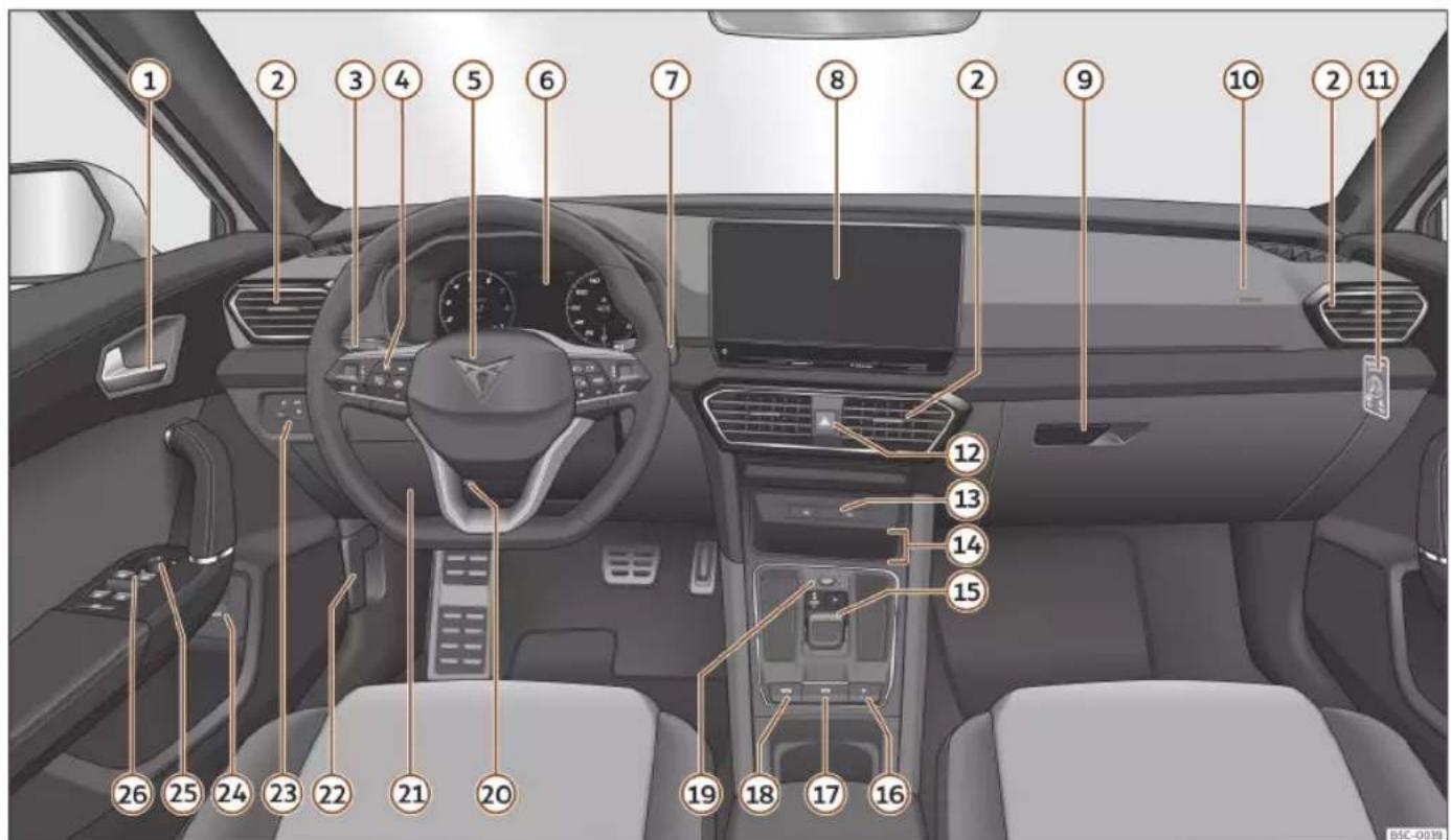
Fig. 50 Instruments and controls.
Controls and displays
Operation
Controls and displays
Interior view
Overview
① Door handle
② Air vents....152
③ Control lever for: - Turn signals and main beam headlights .... 116
4 Switches for: - Driver assistance systems....81 - On-board computer....80 - Controls for radio, telephone, navigation and voice control system....91
⑤ Steering wheel with horn and - Driver airbag....26 - Paddle levers for tiptronic gear- shift (automatic gearbox).... 220
⑥ Instrument panel.... 64
⑦ Control lever for: - Windscreen wipers and washer.... 123 - Wipe and wash system.... 123
- On-board computer ....70
⑧ Infotainment system....162
⑨ Glove compartment....143
10 Front passenger airbag 26
⑪ Front passenger airbag switch ..... 27
⑫ Hazard warning lights ..... 120
13 USB type-C ports 206
14 Connectivity Box 204
15 Depending on the equipment: - Manual gearbox.... 217 - DSG automatic transmission..... 218
16 Central locking switch....97
17 Electronic parking brake switch.... 266
18 Auto Hold switch....268
19 Starter button.... 207
20 Adjustable steering column....15
21 Fuse box....58
22 Bonnet lock release 324
23 Control for lighting and demisting windows.... 114
24 Button to open rear lid....107
25 Control for the electric adjustment of the exterior mirrors.... 126
26 Electric windows....110
Note
- Some of the equipment listed in this section is only fitted on certain models or are optional extras.
- The arrangement of controls on right-hand drive models may be slightly different from the layout shown in»» page 62. However, the symbols used to identify the controls are the same.
Operation
Instruments and warning/control lamps
Instrument panel
Introduction
After switching the engine on with a 12-volt battery that is heavily discharged or newly changed some system settings (such as the time, the date, the personalised comfort settings and the programming) might be altered or deleted. Check and correct these settings once the battery is sufficiently charged.
WARNING
Any distraction may lead to an accident, with the risk of injury.
- Do not operate the instrument panel controls when driving.
- To reduce the risk of accident and injury, only make adjustments to the instructions on the screen of the instrument panel and to the instructions on the screen of the Infotainment system when the vehicle is stationary.
Instruments and warning/control lamps
Digital instrument panel (Digital Cockpit)

Fig. 51 Digital Cockpit on the instrument panel (classic view).
Details of the instruments:
① Control and warning lamps» page 82
② Revolution counter. Revolutions per minute the engine is running»» page 76.
③ Gear engaged or selector lever position
④ Screen display>>> page 67
⑤ Speedometer
⑥ Digital speed display
⑦ Information Profile»» page 65.
The Digital Cockpit is a digital instrument panel with a high-resolution TFT colour
screen. It has a 5 views accessible using the button VIEW of the multifunction steering wheel. By selecting different information profiles, indications other than the classic circular instruments can be displayed, such as navigation data, multimedia information or travel data.
The 6 views are:
• Classic
• Dynamic
- Assistance systems
- Navigation
• Night
• CUPRA
All views will display information on the screen about audio, phone, travel data, vehicle status, navigation 1) and driving aids 1) .
Information profiles
The ☐ / ☐ buttons on the multifunction steering wheel can be used to browse through the different Digital Cockpit information.
Information on the vehicle status, travel data and assistants will be displayed on the left side.
Operation
On the right side information will be displayed on: audio, telephone, compass, navigation manoeuvres and the G-force meter.
Depending on the view in the central area of the Digital Cockpit information about the following will be displayed:
- Classic View and Dynamic View: Initial data, date, distance travelled and autonomy. Turning the right thumbwheel on the multifunction steering wheel: navigation map, road signs, driving data (clicking on OK switches between the different memories).
- Assists View: This is accessed by pressing the button ☑ or the button VIEW on the multifunction steering wheel. Turning the right thumbwheel on the multifunction steering wheel displays the list of assistants. Press OK to turn the desired assistant on/off.
- Navigation View: By pressing the button OK on the multifunction steering wheel and then turning the thumbwheel you can view the map in a larger or smaller view. If you pressed the button OK again, the map returns to automatic scale.
- Night View: The speed is displayed in digital format.
- CUPRA view: The revolutions tube is displayed in the centre.
Classic View
The revolutions per minute and speedometer needles appear in full length by a long press on the button VIEW on the multifunction steering wheel, regardless of the menu displayed in the central area» Fig. 51.
With another long press on the button VIEW, the display will returns to the previous view.
Or looking in the instrument panel menu for the X Close option using the right hand thumbwheel on the multifunction steering wheel, and then press OK.
Information that may be displayed in the central area of the Digital Cockpit speedometer
• Audio
- Telephone
- Compass
- Navigation indications (the most recent destinations are displayed by pressing the arrow on the right of the multifunction steering wheel)
- G-force meter.
- X >OK (close classic view).
Information that may be displayed in the central area of the Digital Cockpit rev counter
- Consumption and average consumption. By pressing the arrow on the left of the multifunction steering wheel, you can switch between the different memories of the travel data.
• Autonomy (fuel tank level).
• Lubricating oil and coolant temperature - Average speed. By pressing the arrow on the left of the multifunction steering wheel, you can switch between the different memories of the travel data.
- Other travel data: km travelled and driving time. By pressing the arrow on the left of the multifunction steering wheel, you can switch between the different memories of the travel data.
- Assist systems.
• Engine power and torque. - X > OK (close classic view).
CUPRA view
Turning the right hand thumbwheel on the multi-function steering wheel scrolls through the following information displayed in the middle of the rev counter:
- Speed and gears.
- Lap timer.
Instruments and warning/control lamps
The following information is displayed outside the rev counter circle:
• Right-hand area: G-force meter.
• Left-hand area: engine power and torque.
Digital instrument panel (Digital Cockpit)
√ Valid for: hybrid vehicles

Fig. 52 Digital Cockpit on the instrument panel (classic view).
Details of the instruments >> Fig. 52 :
① Control and warning lamps»» page 82
② Rev counter and Powermeter. Revolutions per minute the engine is running >> page 77.
③ Gear engaged or selector lever position
④ Screen display>>> page 67
⑤ Speedometer
⑥ Digital speed display
⑦ Information Profile»» page 65.
Status display
Possible indications on the instrument panel display
Different pieces of information can be displayed on the screen of the instrument panel, depending on the features of the vehicle.
• Doors, bonnet and rear lid open
• Warning and information messages
- Odometer
• Time» page 76
- Indications of the radio and navigation system
• Indications of the phone
- Outside temperature
• Indications of the compass
- Selector lever positions
》
Operation
- Gear recommendation (Triptonic mode) >> page 224
- Combined range (hybrid vehicles)
page 68
- Display of travel data (multifunction display) and menus for different settings
page 69
• Service interval display>>>page 79
• Speed warning»» page 70
• Speed warning for winter tyres - Start-Stop system status display
page 214
- Signs detected by the road signs detection system and warning that the maximum permitted speed has been exceeded
page 73
- Indication of active cylinder management status (ACT ® )>>> page 230
• Low consumption driving eco
• Identifying letters on engine (LDM) - Driver assistance system display
page 232
• Copyright
Doors, bonnet and rear lid open
When the vehicle is unlocked and while driving, the instrument panel display shows if any of the doors, the bonnet or rear lid are opened and, in some cases, it is also indicated by an audible warning. The display may
vary according to the type of instrument panel fitted.
Selector control positions (DSG® dual clutch gearbox)
The current position of the selector control is shown on the side of the control and on the instrument cluster display. When the control is in the D/S position or in the Tiptronic position, in some cases, the gear engaged in each case is shown on the instrument cluster display.
Outside temperature indicator
If the outside temperature is lower than approximately +4 °C (+39 °F), the “ice crystal symbol” on the outside temperature display also lights up. This symbol remains lit until the outside temperature exceeds +6 °C (+43 °F) >> △.
When the vehicle is stationary, when the auxiliary heater is switched on or when driving at very low speeds, the outside temperature indicated may be higher than the actual temperature due to the heat produced by the engine.
The margin of measurement ranges from -45 °C (-49 °F) to +76 °C (+169 °F).
Gear-change recommendation
While driving, the instrument panel of certain vehicles may indicate a gear recommendation for saving fuel»» page 224.
Odometer
The odometer registers the total distance travelled by the car.
The partial odometer (trip) shows the distance travelled since the last time it was reset to zero.
To reset the trip odometer (trip) to 0:
- When in Travel data selecttrip.
- Press and hold the OK button of the multifunction steering wheel for approximately 2 seconds.
Combined operating range display (hybrid vehicles)
The value shown is calculated and updated according to the driving style. Therefore, the range can vary even when the fuel tank is full and the high-voltage battery is fully charged.
Range can be increased by reducing or switching off comfort consumers, e.g. air conditioning or seat heating.
Instruments and warning/control lamps
Speed warning for winter tyres
If the maximum set speed is exceeded, this is displayed on the instrument cluster display >> page 69.
The speed warning can be set in the infotainment system using the function button > Vehicle > Exterior > Tyres >> page 89.
Low consumption driving @co
Depending on the equipment, when the vehicle is moving eco is displayed on the instrument cluster display when the vehicle is in an economical consumption status due to active cylinder management (ACT®) >> page 230.
Identifying letters on engine (LDM)
• See Service menu»» page 69.
Copyright
Legal text about the property rights and copyrights of the instrument cluster.
WARNING
Even when the outside temperature is higher than freezing temperature, some roads and bridges could be frozen.
- The "ice crystal symbol" indicates that there may be a risk of freezing.
- At outside temperatures above +4 °C (+39 °F), there may be ice even when the "ice crystal symbol" is not on.
- The outside temperature sensor takes a guideline measurement.
Note
- There are different instrument panels and therefore the versions and instructions on the display may vary. In the case of displays without warning or information texts, faults are indicated exclusively by the control warning lamps.
- Some indications on the instrument panel screen may be concealed by a sudden event, e.g. an incoming call.
- Depending on the equipment, some settings and instructions can be carried out or displayed on the infotainment system as well.
- If there are several warnings at the same time, the symbols will be displayed one after the other for a few seconds. The symbols will stay on until you remove the cause.
- If when switching on the ignition warnings are shown about existing faults, it might not be possible to change the settings or show the information as described. In this case, go to a specialised workshop and request a repair.
Instrument panel menus
The number of menus and information items available will depend on the vehicle's electronics and features.
Some menu options can only be read when the vehicle is stationary.
- Driving data>>> page 70
■ Assist systems.
■ Front Assist On/Off>>> page 240
■ ACC (only display) >>>page 244
■ Lane Assist On/Off >> page 252
■ Side Assist On/Off >> page 258
■ Navigation.
■ Audio.
- Telephone.
■ Vehicle status» page 71
Service Menu
In the Service menu various settings can be adjusted depending on the features.
Open the Service menu
- While in Classic View, go to the Initial Data screen, press the OK button on the multifunction steering wheel for about 5 seconds and release it.
- Next, the Configuration list menu is displayed, where you can choose between »
Operation
the Service menu or the View selection from where the instrument cluster views can be switched on and off.
Restart the service interval display
Select the Service menu and follow the instructions on the screen of the instrument panel.
Restart the oil service
Select the Restore Oil service menu and follow the instructions on the instrument panel display.
Reset driving data (vehicles with an analogue instrument cluster)
Select the Reset trip menu and follow the instructions on the instrument panel display to reset the value.
Identifying letters on engine (LDM)
Select the menu Engine code. The identifying letters of the engine will be shown on the instrument cluster display at the bottom left.
Setting the clock
Select the Time menu and set the correct time by turning the right thumbwheel of the multifunction steering wheel.
Next Service
This specifies when the next workshop inspection is scheduled.
Driving data indicator (multifunction display)
The display of the travel data (multifunction display) shows different values about the journey and the consumption.
Change from one display to another
- Turn the right thumbwheel of the multifunction steering wheel»»page 81.
Changing memory
- Depending on the view, select Trip data and press the left arrow or the OK button on the multifunction steering wheel.
- Since start: The memory is deleted if the journey is interrupted for more than 2 hours.
- Since refuelling: Display and storage of the journey data and the consumption values collected. When refuelling, the memory is deleted.
- Long-term: This memory contains travel data up to a maximum of 19 hours and 59 minutes or 99 hours and 59 minutes, or up to a maximum of 1999.9 km
or 9999.9 km. When one of these values is exceeded (varies depending on the version of the instrument panel), the memory is deleted.
Delete journey data presets
- When in Travel data select desired memory.
- Keep the OK button on the multi-function steering wheel pressed for approximately 2 seconds.
Select the instructions
On the instrument cluster, it is selected manually using the ☐ button on the multifunction steering wheel. To access the contents of the tube, rotate the right hand thumbwheel up/down.
- Current consumption: The current fuel consumption display operates throughout the journey, in litres/100 km; and with the engine running and the vehicle stopped, in litres/hour.
- Average consumption: The average fuel consumption is displayed after driving for approximately 300 metres.
- Travelling time: This indicates the hours (h) and minutes (min) since the ignition was switched on.
Instruments and warning/control lamps
- Range: Approximate distance in km that can still be travelled if the same driving style is maintained.
- AdBlue range or ♂: Approximate distance in km that can still be travelled with the current level of the AdBlue® tank with the same driving style. The indication appears from a range of less than 2,400 km and cannot be deactivated. 1)
- Distance: Distance covered in km (m) after switching on the ignition.
- Average speed: The average speed will be shown after driving for approximately 100 metres.
- Boost/Torque: Indicates the power and torque of the combustion engine (does not indicate electric mode).
– FAS: Reduced assistant indication.
Oil and coolant temperature indication
The engine reaches its operating temperature when, under normal driving conditions, the oil temperature is between 80°C (176°F) and 120°C (248°F). If a great effort is required from the engine and the outside temperature is high, the engine oil temperature may increase. This does not present any problem as long as the warning lamps 📋 or 🌐 >> page 327 do not appear on the display.
Warning and information messages (Vehicle status)
The system runs a check on certain components and functions when the ignition is switched on and while the vehicle is moving. Faults are displayed on the instrument cluster display as red and yellow warning symbols accompanied with messages and, as applicable, even an audible signal» page 82. The representation of the messages and symbols may vary depending on the version of the instrument panel.
Existing faults can also be checked manually. To do so, open the menu Vehicle info >> page 88.
Priority 1 warning (red)
The symbol lights up or flashes (in part accompanied by audible warnings). Stop driving! Danger! Check the fault and eliminate the cause. If necessary, seek professional assistance.
Priority 2 warning (yellow)
The symbol lights up or flashes (in part accompanied by audible warnings). Operating faults or the lack of operating fluids can cause damage to the vehicle or a fault. Check the faulty function as soon as possi-
ble. If necessary, seek professional assistance.
Information message
It provides information about processes in the vehicle.
Accessing warnings and information
- In the infotainment system, press ⏻ > 📁 Vehicle data > Vehicle status.
Driver alert system (break recommendation)

Fig. 53 On the instrument panel display: driver alert system symbol.
»
Operation
The Fatigue detection informs the driver when their driving behaviour shows signs of fatigue.
Function and operation
Fatigue detection determines the driving behaviour of the driver when starting a journey, making a calculation of tiredness. This is constantly compared with the current driving behaviour. If the system detects that the driver is tired, an audible warning is given with a sound and an optic warning is shown with a symbol and complementary message on the instrument panel display >> Fig. 53. The message on the instrument panel display is shown for approximately 5 seconds, and depending on the case, is repeated. The system stores the last message displayed.
The message on the instrument panel display can be switched off by pressing the OK button on the multi-function steering wheel >> page 80.
Conditions of operation
Driving behaviour is only calculated on speeds above about 65 km/h (40 mph) up to around 200 km/h (125 mph).
Switching on and off
Fatigue detection can be activated or deactivated in the infotainment system using the function button ☐ > Assistants > Driver
alerts > Fatigue detection»» page 89. A mark indicates that the adjustment has been activated.
System limitations
The Fatigue detection has certain limitations inherent to the system. The following conditions can limit the Fatigue detection or prevent it from functioning.
- At speeds below 65 km/h (40 mph)
- At speeds above 200 km/h (125 mph)
- When cornering
- On roads in poor condition
• In unfavourable weather conditions - When a sporty driving style is employed
• In the event of a serious distraction to the driver
Fatigue detection will be restored when the vehicle is stopped for more than 15 minutes, when the ignition is switched off or when the driver has unbuckled their seat belt and opened the door.
In the event of slow driving during a long period of time (below 65 km/h, 40 mph) the system automatically re-establishes the tiredness calculation. When driving at a faster speed the driving behaviour will be recalculated.

WARNING
Do not let the comfort afforded by the Fatigue detection system tempt you into taking any risks when driving. Take regular breaks, sufficient in length when making long journeys.
- The driver always assumes the responsibility of driving to their full capacity.
• Never drive if you are tired. - The system does not detect the tiredness of the driver in all circumstances. Consult the information in the section>> page 72, System limitations.
• In some situations, the system may incorrectly interpret an intended driving manoeuvre as driver tiredness. - No warning is given in the event of the effect called microsleep!
- Please observe the indications on the instrument panel and act as is necessary.

Note
- Fatigue detection has been developed for driving on motorways and well paved roads only.
- If there is a fault in the system, have it checked by a specialised workshop.
Instruments and warning/control lamps
Road signs detection system 1)

Fig. 54 On the instrument panel display: examples of recognised signals.
The traffic signal detection system is activated whenever the vehicle ignition is switched on.
The system records the standard traffic signs in front of the vehicle with a camera located on the base of the interior mirror and provides information about speed limits, hazard warnings and overtaking prohibitions.
Within its limitations, the system also displays additional signals, such as time-specific prohibitions, signs for vehicles towing trailers » page 291 or limitations that only apply in the event of rain. Even on journeys without signs, the system may display any applicable speed limits.
The traffic sign detection system does not work in all countries. Keep this in mind when travelling abroad.
Shown on the display
The traffic signs detected by the system are displayed on the dash panel display
Fig. 54 and, depending on the navigation system fitted in the vehicle, on the infotainment system as well>> page 85.
In Germany, on motorways and vehicle roads, besides speed limits and overtaking provisions the system also displays the end of prohibition signs. The valid speed limit at the time in other countries is always shown.
Hazard warning signs are not displayed in the infotainment system.
Road sign detection system messages:
There are no traffic signs available
• The system is in its start-up phase.
- OR: the camera has not recognized any mandatory or prohibitive sign.
Error: Dynamic Road Sign Display
- There is a fault in the system. Have the system checked by a specialised workshop.
Speed warning currently unavailable
- The speed warning function of the road sign detection system is faulty. Have the system checked by a specialised workshop.
Dynamic Road Sign Display: please clean the windscreen.
- The windscreen is dirty in the camera area. Clean the windscreen.
Dynamic Road Sign Display currently restricted.
- The navigation system is not transmitting data. Check if the navigation system has updated maps.
- OR: the vehicle is in a region not included on the navigation system's map.
No data available
- The traffic sign detection system does not work in the current country.
Display of traffic signs
When the traffic sign detection system is connected, a camera located on the base of the interior rear-view mirror records the traffic signs in front of the vehicle. After checking and evaluating the information from the camera, the navigation system and the current vehicle data, up to two valid road signs »
Operation
are displayed, with their corresponding additional signs:
- First position. The sign that is currently valid for the driver is shown in the screen. For example, a maximum speed limit of 130 km/h (100 mph) >> Fig. 54.
- Second position. A second traffic sign may be displayed in the second position, such as a hazard warning sign, an overtaking prohibition or an alternative speed limit.
Additional sign: If the windscreen wiper is working while you are driving, the signal with the additional rain sign will be shown first, on the left, as it is the one that is applicable at the time.
A sign valid only with restrictions, e.g. no overtaking at certain times, may be displayed.
Speed warning (depending on the instrument panel)
If the system detects that the permitted speed is exceeded, it may warn the driver with a "gong" and visually with a message on the dash panel display.
Trailer mode
In vehicles equipped with a towing bracket device from the factory and a trailer that is electrically connected to the vehicle, it is possible to activate or deactivate the display of specific traffic signs for vehicles with trailer, such as speed limits or overtaking prohibitions. It can be activated or deactivated in the infotainment system using the button
Assistants > Driver alerts > Road signs detect. > Consider trailer>>> page 89.
For trailer mode, the display of speed limits applicable to the type of trailer or to the legal provisions can be adjusted. The speed is adjusted in steps of 10 km/h (5 mph) within a range of between 60 km/h (40 mph) and 130 km/h (80 mph). If it is adjusted to a speed greater than that which is permitted in the country in question for driving with a trailer, the system automatically displays the usual speed limits, e.g. in Germany 80 km/h (50 mph).
If the speed warning for the trailer is deactivated, the system displays the speed limits as if there were no trailer hitched.
No entry sign
The traffic sign recognition system warns acoustically and visually in the instrument panel when a no entry sign is crossed on a one-way road or an entrance to a motorway or highway.
Limited operation
The traffic sign detection system has certain limitations. The following cases may lead the system to operate with limitations or not at all:
- In the case of poor visibility, e.g. in snow, rain, fog or intense mist.
- In cases of dazzling, e.g. caused by head-on traffic or by the sun.
- When driving at high speeds.
- If the camera is covered or dirty.
- If the traffic signs are out of the camera's field of vision.
- If the traffic signs are partially or totally covered, e.g. by trees, snow, dirt or other vehicles.
- In the case of traffic signs that do not fulfil the regulations.
- In the case of damaged or bent traffic signs.
- In the case of variable messages on overhead or gantry signs (LED-based variable traffic signs or other lighting units).
- If the maps on the navigation system are not up-to-date.
- In the case of adhesives affixed to vehicles that depict traffic signs, e.g. speed limits on lorries.
WARNING
The technology in the traffic sign detection system cannot change the limits imposed by the laws of physics and only works within
Instruments and warning/control lamps
the system's limits. Do not let the extra convenience afforded by the traffic sign detection system tempt you into taking any risks when driving. The system is not a replacement for driver awareness.
- Adapt your speed and driving style to suit visibility, weather, road and traffic conditions.
- Poor visibility, darkness, snow, rain and fog may lead to the system failing to display traffic signs or not displaying them correctly.
- If the camera's field of vision is dirty, covered or damaged, system operation may be impaired.
WARNING
The driving recommendations and traffic indications shown on the traffic sign detection system may differ from the actual current traffic situation.
- The system may not detect or correctly show all the traffic signs.
- Traffic signs and traffic regulations have priority over the recommendations and displays provided by the system.
WARNING
If messages are ignored, the vehicle may stall in traffic and cause accidents and severe injuries.
• Never ignore the messages displayed.
- Stop the vehicle at the next opportunity and in a safe place.
Note
To avoid affecting the correct operation of the system, take the following points into consideration:
- Regularly clean the area of vision of the camera and keep it in a clean state, without snow or ice.
- Do not cover the field of vision of the camera.
- Always replace damaged or worn blades when required to avoid lines on the camera's field of vision.
- Check that the windscreen is not damaged in the area of the camera's field of vision.
- The use of outdated maps on the navigation system may cause the system to show traffic signs incorrectly.
- In the waypoints mode of the navigation system, the traffic sign detection system is only partly available.
- Failure to heed the control lamps and corresponding text messages when they light up may result in damage to the vehicle.
Eco-efficient driving assistance
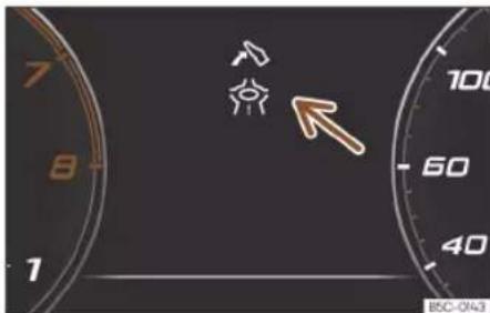
Fig. 55 Eco-efficient driving assistance indication (schematic representation).
Eco-efficient driving assistance helps you drive with care and with low energy consumption by following instructions superimposed in the digital cockpit, depending on the situation.
When you approach places such as a junction, a roundabout or a section of road with a speed limit, the symbol → is displayed along with an event in the digital cockpit Fig. 55.
WARNING
The system is not a replacement for driver awareness.
- Adapt your speed and driving style at all times to suit visibility, weather, road and traffic conditions.
• Traffic signs on the road and traffic regulations have priority over eco-driving notes.
Operation
Note
- The appearance of the symbols may vary slightly depending on the equipment and model. System updates may modify or expand the symbols.
- When the system is switched on, eco-efficient driving assistance can also increase recuperation without any indication being displayed. This can occur in situations such as when the accelerator pedal is released when a vehicle is driving in front. In this case, energy recuperation is adapted match the speed of the vehicle in front without any indication being displayed.
Time
Setting the time on the infotainment system
- Press Settings.
- Select the menu option Time and date to set the time»» page 85.
Revolution counter
The rev counter indicates the number of engine revolutions per minute.
Together with the gear-change indicator, the rev counter offers you the possibility of using the engine of your vehicle at a suitable speed.
The beginning of the red zone of the rev counter indicates the maximum speed in any gear after running-in and with the engine hot. However, it is advisable to move the selector lever to D or lift your foot off the accelerator before the needle reaches the red zone >> 0.
We recommend that you avoid high revs and that you follow the recommendations on the gear-change indicator. Consult the additional information in»» page 224, Selecting the optimal gear.
Speed limiter 1)
If the indicator light turns on, the engine will be automatically limited to the speed shown on the instrument cluster. This protects the engine components in situations such as a cold start or against overheating.
The engine speed limiter is released as soon as the engine reaches normal operating temperature and the takes his/her foot off the accelerator.
If the engine speed limitation is caused by an engine management fault, the ◄ indicator light also lights up. Make sure the displayed RPM is not exceeded (for example, by reducing it). Go immediately to a specialised workshop to have the fault repaired.
The flashing indicator warns the driver that the engine RPM limit has been reached.
The flashing indication is displayed in the upper areas of the rev counter by green, yellow and red areas.
When the RPM approaches the limit, the flashing indicator flashes red. Shift up a gear at the right time.
CAUTION
- To prevent damage to the engine, the rev counter needle should only remain in the red zone for a short period of time.
Instruments and warning/control lamps
- When the engine is cold, avoid high revs and heavy acceleration and do not make the engine work hard.

For the sake of the environment
Changing up a gear early will help you to save fuel and minimise emissions and engine noise.
Power meter
√ Valid for: hybrid vehicles

Fig. 56 Digital instrument panel: Power-meter (classic view)

Fig. 57 Digital instrument panel: Power-meter (Cupra view)
The lower left hand side of the rev counter has two colour coded areas:
Green Charge: Energy recovery zone.
Blue Power %: Electric traction zone. Indicates the percentage of power used and the maximum amount of power currently available.
The power meter shows the usage level of the electric drive. The power meter bar shows the current usage level.
A finer coloured border indicates how much the propulsion can currently be used. Depending on the selected driving program and the current availability of electrical power, the boundaries of the different colours can vary.
The following displays can be seen on the Power meter:
>>> Fig. 56,>>> Fig. 57
Ⓐ The vehicle recovers electrical energy.
B e-Mode electric driving.
C The combustion engine must be running. With the Boost function, the vehicle drives for a short period of time with maximum power from both the electric motor and the combustion engine.
Battery level indicator
√ Valid for: hybrid vehicles

Fig. 58 Digital instrument panel: battery level indicator.
The small arrow next to the battery symbol on the fuel gauge indicates which side of the vehicle the charging cover is on.

Note
- Never drive with the tank completely empty. Under certain circumstances, the
Operation
energy stored in the high-voltage battery may not be sufficient to reach the nearest service station.
- When the outside temperature is very low, and therefore the high-voltage battery is very cold, difficulties may arise in starting the internal combustion engine and the range in the electric driving mode may be reduced.
Fuel gauge

Fig. 59 Fuel gauge located in different positions depending on the view.
Control lamps

It lights up yellow
Fuel tank almost empty. The fuel reserve level has been reached >>> ⚠️. Refuel as soon as you have the opportunity.

It lights up yellow
Presence of water in diesel.
Turn off the engine and seek professional assistance.
The display only works when the ignition is switched on.
The fuel range is displayed on the instrument panel.
You can consult the tank capacity of your vehicle in the»»page 367 section.
WARNING
When driving with low fuel, the vehicle may stall in traffic and cause accidents and severe injuries.
- If the fuel tank level is too low, fuel could reach the engine irregularly, particularly when driving up or down slopes.
- The steering system and the driver assistance systems and brakes do not work when the engine is running irregularly or switches off due to lack of fuel or an irregular supply thereof.
• Always refuel when there is only one quarter of fuel in tank to prevent the vehicle to stop due to lack of fuel.
CAUTION
Never run the fuel tank completely dry. An irregular fuel supply can cause misfiring and unburnt fuel could enter the exhaust system. The catalytic converter or the particulate filter may get damaged!
Note
The small arrow on the fuel gauge next to the fuel pump symbol points out towards the side of the vehicle with the fuel tank flap.
Coolant temperature indicator.
The coolant temperature view can be selected in the corresponding menu»» page 66.
Control and warning lamp

It lights up red
Do not carry on driving!
Engine coolant level too low, coolant temperature too high.

Flashes red
Fault in the engine coolant system.
- Stop the vehicle, switch off the engine and let it cool down.
- Check the engine coolant level >>page 329.
- If the warning lamp does not switch off even if the coolant level is correct, request assistance from specialised personnel.
Instruments and warning/control lamps
Control and warning lamps (valid for hybrid vehicles)

It lights up red
Do not carry on driving!
Engine or high-voltage system coolant level too low, engine or high-voltage system coolant temperature too high.

and
Flashes red
Do not carry on driving!
Failure in the high-voltage cooling circuit. Disconnect the drive system and seek professional assistance.
- Stop the vehicle, switch off the engine and let it cool down.
- Check the engine coolant level >> page 329.
- Check the coolant level in the high-voltage cooling circuit» page 330. If the level is too low DO NOT add coolant. Seek specialist assistance immediately.
- If the warning lamp does not switch off even if the coolant level is correct, request assistance from specialised personnel.

CAUTION
• To ensure a long useful life for the engine, avoid high revs, driving at high speed and making the engine work hard for approximately the first 15 minutes when the engine is cold. The phase until the engine is warm
also depends on the outside temperature. If necessary, use the engine oil temperature» page 71 as a guide.
• Additional lights and other accessories in front of the air inlet reduce the cooling effect of the coolant. At high outside temperatures and high engine loads, there is a risk of the engine overheating.
- The front spoiler also ensures proper distribution of the cooling air when the vehicle is moving. If the spoiler is damaged this can reduce the cooling effect, which could cause the engine to overheat. Seek specialist assistance.
Service intervals
The service interval display appears on the instrument cluster screen and in the info-tainment system.
There are different versions of instrument panels and infotainment systems, so the versions and instructions on the screens may vary.
CUPRA distinguishes between services with engine oil change (e.g. Oil change service) and services without engine oil change (e.g. Inspection).
In vehicles with Services established by time or mileage, the service intervals are already pre-defined.
In vehicles with LongLife Service, the intervals are determined individually. Thanks to technological progress, maintenance work has been greatly reduced. Because of the technology used by CUPRA, with this service you only need to change the oil when the vehicle so requires. To calculate this variation (max. 2 years), the vehicle's conditions of use and individual driving styles are considered. The advance warning first appears 20 days before the date established for the corresponding service. The kilometres (miles) remaining until the next service are always rounded up to the nearest 100 km (miles) and the time is given in complete days. The current service message cannot be viewed until 500 km after the last service. Prior to this, only lines are visible on the display.
Inspection reminder
If a service or an inspection has to be carried out soon, a service reminder will be displayed when the ignition is switched on.
The figure displayed are the kilometres that can still be travelled or the time until the next service.
Service due
When the time for a service or an inspection comes, an audible warning will be emitted when the ignition is switched on and the »
Operation
fixed key symbol → may appear on the instrument panel for a few seconds, along with one of the following messages:
• Service now!
- Please have your vehicle inspected.
- Oil change service due!
- Oil change service and inspection due!
Consult a service notification
With the ignition switched on, the engine off and the vehicle at a standstill, the current service notification can be read:
Check the date of the current service on the infotainment system
- Press Settings.
- Select the Data connection menu option to display information about services.
Checking the date on the digital instrument panel
- The date of the service can only be read through the Service menu»» page 69.
Resetting service interval display
If the service was not carried out by a specialised CUPRA dealer or any dealer in the SEAT network, the display can be reset as follows:
- The service interval display can only be reset through the Service menu»»page 69.
Do not restart the indicator between the service intervals, otherwise the information displayed will be incorrect.
If the oil change service is reset manually, the service interval display changes to a fixed service interval, also in vehicles with Flexible oil change service.
Note
- The service message disappears after a few seconds, when the engine is started or when the OK button is pressed on the multifunction steering wheel.
- In vehicles with the LongLife system in which the battery has been disconnected for a long period of time, it is not possible to calculate the date of the next service. Therefore the service interval display may not be correct. In this case, bear in mind the maximum service intervals permitted >> page 350.
- If you reset the display manually, the next service interval will be indicated as in vehicles with fixed service intervals. For this reason we recommend that the service interval display be reset by an authorised dealer.
Using the instrument panel
Introduction
With the ignition switched on, it is possible to read the different functions of the display by scrolling through the menus.
The multifunction display can only be controlled from the buttons on the multi-function steering wheel.
Some menu options can only be read when the vehicle is at a standstill.
WARNING
Distracting the driver in any way can lead to an accident and cause injuries.
- Never use the menus on the instrument panel display while the vehicle is in motion.
Note
After loading or changing the 12-volt battery, check the system settings. If the power supply is interrupted, the system settings might be incorrect or deleted.
Instruments and warning/control lamps
Operation using the multifunction steering wheel

Fig. 60 Right side of the multifunction steering wheel: buttons for using the instrument cluster's menus and information displays (depending on versions).
As long as a priority 1»»page 71 warning is active, it will not be possible to access any menu. Some warnings can be confirmed and hidden with the button OK of the multifunction steering wheel >>Fig. 60.
Select a menu or an informative display
- Switch the ignition on.
- If a message or vehicle symbol is displayed, press the button OK>>>Fig. 60; if necessary, several times.
- To change menus, use buttons □ or □ >> Fig. 60.
- To open the menu or the information displayed, press the button OK>>> Fig. 60 or wait
a few seconds until the menu or the informative display opens automatically.
Changing menu settings
- In the menu displayed, turn the right thumbwheel of the multifunction steering wheel» Fig. 60 until the desired option of the menu is highlighted. The option appears framed.
- Press the button OK>>> Fig. 60 to make the required modifications. A mark indicates that the system or function is activated.
Back to menu selection
Press the button☐ or ☐>>> Fig. 60.
Button for the driver assistance systems

Fig. 61 On the turn signal and main beam lever: button for driver assistance systems (depending on versions).

Fig. 62 Left side of the multifunction steering wheel: button for driver assistance systems (depending on versions).
Operation
With the turn signal and main beam head-light lever button, you can activate or deactivate the driver assistance systems displayed in the Assistance systems menu.
Activating or deactivating a driver assistance system using the turn signal lever and main beam headlight
- Briefly press the>>> Fig. 61 ① button to open the Assistants menu.
- Select the driver assistance system and activate or deactivate it»» page 80. A mark indicates that driver assistance system is switched on.
- Next, confirm the selection by pressing the OK button on the multi-function steering wheel.
Activating or deactivating a driver assistance system using the multifunction steering wheel
- Press the button 📄>>> Fig. 62 to open the Aids menu.
- Select the driver assistance system and activate or deactivate it. A mark indicates that driver assistance system is switched on.
- Next, confirm the selection by pressing the OK button on the multifunction steering wheel.
The driver assistance systems can also be switched on and off in the infotainment sys-
tem, in the menu Vehicle settings >>> page 89.
Control lamps
Control and warning lamps
The control and warning lamps are indicators of warnings>>> ⚠️ faults or certain functions. Some control and warning lamps come on when the ignition is switched on, and switch off when the engine starts running, or while driving.
Depending on the model, additional text messages may be viewed on the instrument panel display. These may be purely informative or they may be advising of the need for action»» page 64, Instrument panel .
Depending upon the equipment fitted in the vehicle, instead of a warning lamp, sometimes a symbol may be displayed on the instrument panel.
When certain control and warning lamps are lit, an audible warning is also heard.
Red warning lamps

Notification central lamp: additional information on the instrument panel display

Parking brake on»» page 264.

Fault in the brake system»» page 264.

Fault in the steering system >> page 226.

Driver or passenger has not fastened seat belt » page 16.

Engine or high voltage system coolant (hybrid vehicles) >> page 78.

Engine oil pressure >> page 327.

Anomaly in the alternator»» page 334.

Press the foot brake» page 244.

AdBlue level too low, OR fault in the SCR system»» page 319.

Drive system»» page 212 >> page 310
Yellow warning lamps

Notification central lamp: additional information on the instrument panel display

Front brake pads worn»» page 264.

Fault in the ESC or the system caused it to switch off; OR ESC or TCS operating >> page 269.

TCS switched off manually; OR ESC in Sport mode; OR ESC switched off manually
page 269.

Fault in the ABS >> page 269.

Electronic parking brake faulty.
Instruments and warning/control lamps
| Rear fog light switched on»» page 114. | |
| Fault in the emission control system»»page 321. | |
| Pre-heating of the diesel engine; OR fault in the management of the diesel engine»»page 321. | |
| EPC | Fault in the petrol engine management»»page 321. |
| Particulate filter blocked»» page 321. | |
| Fault in the steering system»»page 226. | |
| Tyre pressure monitor system»»page 346. | |
| Drive system»» page 212 | |
| Vehicle sound»» page 212 | |
| Fuel tank almost empty»» page 78. | |
| Adblue level low, OR fault in the SCR system»»page 319. | |
| Fault in airbag system and seat belt tension-ers»» page 25. | |
| OFF | Front passenger front airbag is disa-bled»» page 25. |
| ON | The front passenger front airbag is activated»»page 25. |
| Defective cruise control system (GRA) »»page 238. | |
| ! LIM | Defective speed limiter»»page 239 |
| Defective active cruise control (ACC) »»page 249 | |
| Lane Assist (lane keeping system) »»page 252. | |
| Error in the lane assist warning system »»page 252. | |
| Lane Assist switched off»» page 252 . | |
| Travel Assist error»»page 256 . | |
| Fault in the lighting of the vehicle »»page 114. | |
| Low engine oil level»»page 327 . | |
| Fault in the gearbox»» page 223 . | |
| Engine speed limitation»»page 76 . |
Green indicator lamps
| Turn lights or emergency lights on »»page 114. | |
| Trailer turn signals»» page 114 . |
| (A) | Auto Hold active (lights green), or Auto Hold paused (lights white)>>> page 268. |
| Charging system>>> page 308 | |
| Press the foot brake>> page 218. | |
| Cruise control system (GRA)>>> page 236. | |
| Speed limiter >> page 238 | |
| Adaptive cruise control (ACC)>>> page 245. | |
| Lane assist active (Lane Assist) warning >> page 252. | |
| Travel Assist active,>> page 255. | |
| Auxiliary heater,>> page 156. |
Blue indicator lamps
| ID | Main beam on or flasher on » page 114. |
| Other warning lamps | |
| Door(s), rear lid or bonnet open or not properly closed» page 68 . | |
| Main beam assist (Light Assist)» page 114 . | |
| Hill descent control (HDC)» page 225 . | |
| Service interval display » page 79 . | |
| Mobile phone connected by Bluetooth® . | |
| Mobile telephone battery charge status. | |
Operation

Risk of freezing>>> page 68.

Start-Stop system activated» page 214.

Start-Stop system unavailable» page 214.
WARNING
If the warning lamps and messages are ignored, faults may occur in the vehicle, it may stall in traffic, or accidents and serious injuries may occur.
- Never ignore the warning lamps or text messages.
- Stop the vehicle safely as soon as possible.
- A faulty vehicle represents a risk of accident for the driver and for other road users. If necessary, switch on the hazard warning lamps and put out the warning triangle to advise other drivers.
- Before opening the bonnet, switch off the engine and allow it to cool.
- In any vehicle, the engine compartment is a hazardous area and could cause severe injuries»» page 322.
Instruments and warning/control lamps
Infotainment system
Introduction
The infotainment system brings together important vehicle functions and systems into a single central control unit, e.g. air conditioning, menu settings, radio equipment and the navigation system.
The actual number of menus available and the name of the various options will depend on the vehicle's electronics and equipment.
General operating information
General information on the operation of the infotainment system, as well as on the warning and safety instructions that must be taken into account, is found in» page 162.
How to move through the different menus and select them
- Switch the ignition on.
- If the infotainment system is off, switch it on.
- The different menus are selected directly on the touch screen using texts, icons or buttons.
If the box is checked√, the function is activated.
Pressing the menu button< will always take you to the last menu used.
Any changes made using the settings menus are automatically saved on closing those menus.
Scroll bar: Some menus and functions show more content above or below those displayed on the screen at that time, for exam-
ple, long lists of settings. Press on the scroll bar and pull up or down.
Tutorial
The first time you connect the Infotainment system, a system tutorial will open with a brief description of the main functions and how to use it.
Help
In the Help menu can be found more information and tips for using the infotainment system.
WARNING
Any distraction may lead to an accident, with the risk of injury. Operating the Infotainment system while driving could distract you from traffic.
Operation
Explanation of the function buttons

Fig. 63 Schematic representation: Overview of the possible function buttons on the screen
Top part of the screen
The following information is always visible, even when the infotainment system is turned off»» Fig. 63 :
A Time, Incoming call or pre-air conditioning on/off.
B Climabar»» page 149.
© Status bar. System customisation based on user and notifications.
Bottom part of the screen
D Main menu display mode:
(3): main menu with the 6 main functions divided into 2 screens (3 + 3, customisable by the user by pressing on the function).
: main menu in mosaic mode (all functions of the Infotainment system)
Direct accesses to the functions of the Infotainment system (up to 10 functions, 5 + 5, customisable by the user). The functions in question can be edited by pressing and holding the icon (replace icons, delete icons or change their order).
F Direct access to the Assistants, Driving profiles, background lighting and vehicle settings»» page 89.
Instruments and warning/control lamps
Initial configuration wizard
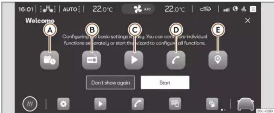
Fig. 64 Schematic representation: Initial configuration wizard
The initial configuration wizard will help you to set up your Infotainment system the first time you switch it on.
Whenever you switch on the infotainment system, the initial setup screen will be displayed» Fig. 64 if any parameters have not been set (marked with “√”) or if the Don’t show again function button has not been pressed.
Function button: Function

Closes the Configuration Wizard.
Function button: Function
| A | Press to set day and time. |
| B | Press to search and store to memory the radio stations that have the best reception at that moment. |
| C | Press to go to the Online Media settings. |
| D | Press to link your mobile phone to the Infotainment system. |
Function button: Function
| E | Press to select your home address using your current position or by manually entering an address. |
| Don't show again | Disables the possibility of changing the settings of the Infotainment system. If you want to run the initial configuration, it can be accessed through ⚙ Settings > Initial configuration wizard. |
| Start Starts up the Configuration Wizard. | |
| End | Once one or more settings have been applied, press to finalise the setup in the main menu of the wizard. |
Operation
Vehicle information
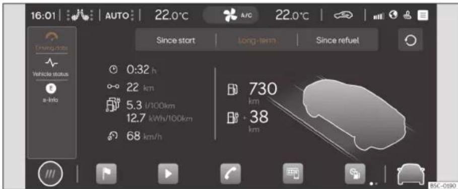
Fig. 65 Schematic representation: Vehicle information and status
Pressing on 📄 Vehicle info in the main menu opens the Vehicle info menu with the following submenus:
- Driving data: The average consumption, average speed, distance travelled, trip duration and autonomy are shown. It has 3 memories: "Since start", "Long-term" and "Since refuel"» page 70.
- Vehicle status: The warnings regarding faults, incidents, memorisation of the tyre pressure or information of the next inspection service are displayed.
- e-Info: shows the electric range and power flow»»page 213.
Instruments and warning/control lamps
Assist systems and vehicle settings

Press 📄 >> Fig. 66 Ⓐ, or Vehicle settings in the main menu to open the assistants and vehicle settings menu. Next, clicking on any of the menus located in the left area Ⓑ, displays the settings menu or the selected assist systems on the display.
The number of assist systems and settings depend on the version and the country in question.
■ Assistance systems
- Parking
■ Automatic parking brake activation >> page 266.
■ Park assist>>> page 274.
■ Smart Assistants
■ Activate / deactivate ESC, stabilisation systems and brake assist» page 269.
■ Activate / deactivate the Start-Stop system»»page 214.
■ Adaptive cruise control (ACC) >> page 244.
■ Lane Assist (lane keeping system) >> page 252.
Emergency brake assistance system (Front Assist)>>> page 240.
- Driving Assist (Travel Assist) >> page 254
Emergency Assist»» page 256.
■ Speed limiter.
- Driver alerts
■ Fatigue detection»» page 71.
Fig. 66 Schematic representation: Assist systems and vehicle settings
■ Traffic sign recognition»»page 73.
■ Lane assist>> page 258.
■ Drive Profile>> page 226
■ Background lighting>>> page 122
■ Vehicle
■ Instrument panel>>> page 67.
■ Lighting >> page 121.
■ Rear view mirrors>>> page 125.
■ Closing>>> page 92.
■ Lights>>> page 114.
■ Windows>>> page 110.
■ Tyres>>> page 346.
■ Comfort light>>> page 121
■ Windscreen wipers>>>page 123
Operation
■ Electric drive (PHEV hybrid vehicles) . >> page 211
■ Seats>> page 128
Farewell screen

Fig. 67 Schematic representation: farewell screen.
When the ignition is switched off, the Farewell Display gives you relevant information before you leave the vehicle.
Fig. 67
A Change the order of the warnings.
B Closes the farewell screen.
Instruments and warning/control lamps
Multifunction steering wheel
Functions

Fig. 68 Controls on the steering wheel.

Fig. 69 Controls on the steering wheel.
The steering wheel includes multifunction modules from where it is possible to control the audio, telephone, navigation, voice control and assist functions without the driver needing to be distracted from the road.
Buttons available depending on the version
| Symbol Function | |
| 1 | Turn: Turn volume up/downPress: Mute volume |
| 2 | Turn: Search in the instrument panel menu. In Navigation mode, turn to zoom in/out of the map in the Digital CockpitPress: Select the highlighted option in the instrument panel |
| Radio: Search for the previous/next station.Media: Short press: previous/next track; long press: fast forward/rewind | |
| Activate phone menu (answer call, end call) | |
| Switch between media and radio sources | |
| Change the instrument panel menu (previous/next) | |
| Enable/disable voice control | |
| VIEW | Digital Cockpit: Change digital panel views» page 65 |
| Activate or deactivate steering wheel heating» page 154 | |
| Symbol Function | |
 | Connect/disconnect the Cruise control system»» page 236 / ACC»»page 244 / Speed limiter»»page 238 |
| SET RES | SET Activate ACC / Cruise control system / LimiterRES Reset programmed ACC speed or cruise control system |
 | +: Increase programmed speed-: Decrease programmed speed |
 | Switching Travel Assist on and off»»page 254 |
 | Open the drive assist menu in the instrument panel |
 | Modify the programmed ACC distance |
 | Driving profile selection»» page 226 |
 | Starting and stopping the engine»»page 207 |
Operation
Opening and closing
Set of vehicle keys
Vehicle key

Fig. 70 Vehicle key

Fig. 71 Centre console: vehicle key socket.
Key to>>>Fig. 70
① Unlock the vehicle
② Lock the vehicle
③ Unlock only the rear lid. Press the button until all the turn signals on the vehicle flash briefly. You have 2 minutes to open the rear lid. Once this time has passed, it will lock again. In addition, the lamp on the key flashes.
④ Control lamp
⑤ Alarm button. Only press in the event of an emergency! When the alarm button is pressed, the vehicle's sounds and the turn signals light up for a short time. Press again to disconnect.
With the vehicle key the vehicle may be locked or unlocked remotely»» page 95.
The vehicle key includes an emitter and battery. The receiver is in the interior of the vehicle. The range of the vehicle key with remote control and new battery is several metres around the vehicle.
If it is not possible to open or close the vehicle using the remote control key, this should be re-synchronised» page 94 or the battery changed» page 94.
Different keys belonging to the vehicle may be used.
Control lamp on the vehicle key
When a button on the vehicle key is briefly pressed, the indicator lamp flashes ④ >> Fig. 70 once briefly, but if the button is
held down for a longer period it will flash several times, such as for convenience opening.
If the vehicle key control lamp does not light up when the button is pressed, replace the key's battery» page 94.
Key socket
There is a key socket near the start button
Fig. 71. Warning! Do not confuse with the location for the emergency start page 210.
Spare key
To obtain a spare key and other vehicle keys, the vehicle ID number is required.
Each new key contains a microchip which must be coded with the data from the vehicle electronic immobiliser. A vehicle key will not work if it does not contain a microchip or the microchip has not been encoded. This is also true for keys which are specially cut for the vehicle.
The vehicle keys or new spare keys can be obtained from a specialised CUPRA dealer or SEAT Official Service, a specialised workshop or an approved key service qualified to create this kind of key.
New keys or spare keys must be synchronised before use>>> page 94.
Opening and closing

WARNING
- Never leave children or disabled persons in the vehicle. In case of emergency, they may not be able to leave the vehicle or manage on their own.
- An uncontrolled use of the key could start the engine or activate any electric equipment (e.g. electric windows), causing risk of accident. The doors can be locked using the remote control key. This could become an obstacle for assistance in an emergency situation.
- Never forget the keys inside the vehicle. An unauthorised use of your vehicle could result in injury, damage or theft. Therefore always take the key with you when you leave the vehicle.
- Never remove the key from the ignition if the vehicle is in motion. Otherwise, the steering could suddenly block and it would be impossible to steer the vehicle.

CAUTION
All of the vehicle keys contain electronic components. Protect them from damage, impacts and humidity.

Note
- Only use the key button when you require the corresponding function. Pushing the button unnecessarily could accidentally unlock the vehicle or trigger the alarm. It is
also possible even when you are outside the radius of action.
• Key operation can be greatly influenced by overlapping radio signals close to the vehicle working in the same range of frequencies, for example, radio transmitters or mobile telephones.
- Obstacles between the remote control and the vehicle, bad weather conditions and discharged batteries can considerably reduce the range of the remote control.
- If the buttons of the vehicle key are pressed or one of the central locking buttons»» page 97 is pressed repeatedly in short succession, the central locking briefly disconnects as protection against overloading. The vehicle is then unlocked. Lock it if necessary.
- Spare remote control keys are available at your Technical Service, where they must be matched to the locking system.
- Up to five remote control keys can be used.
Pull out the key blade

Fig. 72 Vehicle key: remove the key blade.
The central locking remote control has the key blade inside it for use in case of emergency locking/unlocking of the driver's door >> page 104.
- If you press button» Fig. 72 ① once the key blade is unlocked and a ring appears as a key ring.
- Press and hold the button ① and at the same time pull on the ring in the direction of arrow>> Fig. 72 ② to completely remove the key blade.
Operation
To change the battery

Fig. 73 Vehicle key: opening the battery compartment cover.

Fig. 74 Vehicle key: removing the battery.
CUPRA recommends you ask a specialised workshop to replace the battery.
The battery is located to the rear of the vehicle key, under a cover.
Changing the battery
- Remove the key blade from the vehicle key >> page 93.
- Insert the key blade into the slot>> Fig. 73, press it in the direction of arrow① and detach the cover by levering it②.
- Extract the battery from the compartment using a suitable thin object» Fig. 74.
- Insert the new battery and press it into the battery compartment >>>
- Place the cover and press it into the vehicle key housing until it clicks into place.
WARNING
Swallowing a battery with a 20 mm diameter or any other button battery can cause serious and even fatal injuries within a very short time.
- Keep the vehicle key and key fobs with batteries out of reach of children.
- If you suspect that someone may have swallowed a battery, seek immediate medical attention.
CAUTION
- If the battery is not changed correctly, the vehicle key may be damaged.
- Use of unsuitable batteries may damage the vehicle key. For this reason, always replace the dead battery with another of the same voltage, size and specifications.
- When fitting the battery, check that the polarity is correct.
For the sake of the environment
Please dispose of your used batteries correctly and with respect for the environment.
Synchronize the vehicle key
If the 🔒 button is pressed frequently outside of the vehicle range, it is possible that the vehicle can no longer be locked or unlocked using the key. In this case, the key must be resynchronised as described below:
- Remove the key blade from the vehicle key >> page 92.
- Press the button on the vehicle key. For this, it must remain with the vehicle.
- Open the vehicle within one minute using the key blade. The key has been synchronised.
- If necessary, fit the cap.
Opening and closing
Central locking
Introduction
Central locking functions correctly when all the doors and the rear lid are correctly shut. If the driver door is open, the vehicle cannot be locked with the key.

WARNING
The incorrect use of the central locking system may cause serious injuries.
- The central locking system will lock all doors. A vehicle locked from the inside can prevent any non-authorised individual from opening the doors and accessing the vehicle. Nevertheless, in case of emergency or accident, locked doors will complicate access to the vehicle interior to help the passengers.
- Never leave children or disabled people alone in the vehicle. The central locking button can be used to lock all the doors from within. Therefore, passengers will be locked inside the vehicle. Individuals locked in the vehicle can be exposed to very high or very low temperatures.
- Depending on the time of the year, temperatures inside a locked and closed vehicle can be extremely high or extremely low resulting in serious injuries and illness or even death, particularly for young children.
- Never leave individuals locked in a closed and locked vehicle. In case of emergency, they may not be able to exit the vehicle by themselves or get help.
Description
Central locking allows all doors, the rear lid and the tank flap to be unlocked centrally:
- From outside, using the vehicle key >>> page 96.
- From outside with the Keyless Access >> page 98 system,
- From inside, by pushing the central locking button»» page 97.
Various functions are available to improve the vehicle safety:
• Security system "Safe">>> page 101
• Self-locking system to prevent involuntary unlocking
- Selective unlocking system
• Automatic speed dependent locking and unlocking system (Auto Lock)
• Emergency unlocking system
Self-locking system to prevent involuntary unlocking
It is an anti-theft system and prevents the unintentional unlocking of the vehicle. If the vehicle is unlocked and none of the doors (including the boot) are opened within 30 seconds, it re-locks automatically.
Unlocking one side of the vehicle only
When you lock the vehicle with the key, the doors and the rear lid are locked. When you open the door, you can either unlock only the driver door, or all the vehicle doors. To select the required option, use the Infotainment system setting»» page 96.
Automatic locking (Auto Lock)
The Auto Lock function locks the doors and the rear lid when the vehicle exceeds a speed of about 15 km/h (9 mph).
The vehicle can be unlocked via the central locking switch or by pulling one of the door handles.
In the event of an accident in which the air-bags inflate, the doors will be automatically unlocked to facilitate access and assistance.
Turn signals
The turn signals will flash twice when the vehicle is unlocked and once when the vehicle is locked.
»
Operation
If it does not flash, this indicates that one of the doors, the rear lid or the bonnet is not closed correctly.
Accidental lock-out
The central locking system prevents you from being locked out of the vehicle in the following situations:
- If the driver door is open, the vehicle cannot be locked with the central locking switch >> page 97.
Lock the vehicle with the remote control key, when all the doors and the rear lid have been closed. This prevents the accidental locking of the vehicle.

Note
- Never leave any valuable items in the vehicle unattended. Even a locked vehicle is not a safe.
- If the LED on the driver door sill lights up for about 30 seconds when the vehicle is locked, the central locking system or anti-theft alarm is not working properly. You should have the fault repaired at a specialised CUPRA dealer, SEAT Official Service or specialised workshop.
- Vehicle interior monitoring by the anti-theft alarm system will only function as intended if the windows and sunroof are closed.
Central locking settings
Central locking settings can be changed in the Infotainment system.
Unlocking doors
- Press the function button > Vehicle > Exterior > Central locking > Door unlocking.
You can choose to unlock all the doors or only the driver door when you unlock the vehicle. In all the options, the fuel tank flap is also unlocked.
With the Driver setting, when you press the button on the remote control key once, only the driver door is unlocked. If that button is pressed twice, the rest of the doors and the rear lid will be unlocked.
If the ☐ button is pressed, all the vehicle doors are locked. At the same time, a confirmation signal is heard.
Unlock and lock from the outside

Fig. 75 Remote control key: buttons.
- Lock: press the Fig. 75 button.
- Locking the vehicle without the "Safe" security system: push the ☐ button again and hold for 2 seconds.
- Unlock: press the 🔊 button.
- Unlocking the rear lid: hold down the button for at least 1 second.
The vehicle will be locked again automatically if you do not open one of the doors or the rear lid within 30 seconds after unlocking the car. This function prevents the vehicle from remaining unlocked if the unlocking button is pressed by mistake. This does not apply if you press the ≈ button for at least one second.
Opening and closing
Selective unlocking system
The selective unlocking system allows you to only unlock the driver door and the fuel tank flap. All other doors and the rear lid remain locked.
Unlocking the driver's door and tank flap:
- Press (once) the 🔑 button on the remote control key or turn the key once in the opening direction.
Unlocking all the doors, the rear lid and the tank flap simultaneously:
- Within 5 seconds, press (twice) the button on the remote control key, or turn the key twice within 5 seconds in the opening direction.
The Safe security system and the anti-theft alarm deactivate immediately when only the driver door is opened.
In vehicles with Infotainment system, you can programme the security central locking system directly» page 96.
WARNING
Observe the safety warnings» in Locking system "Safe" on page 101.
Note
- Do not use the remote control key until the vehicle is visible.
- Other functions of the remote control key» page 111, Convenience open/close function.
Unlocking and locking from the inside

Fig. 76 In the centre console: central locking switch
- Lock: press the 📄» Fig. 76 button.
- Unlock: Press the ☐ button again
Fig. 76.
Please note the following when using the central locking switch to lock your vehicle:
- It is not possible to open the doors or the rear lid from the outside (for safety reasons, e.g. when stopped at traffic lights).
-
The LED in the central locking switch lights up when all the doors are closed and locked.
-
You can open the doors individually from the inside by pulling the inside door handle.
- In the event of an accident in which the airbags inflate, doors locked from the inside will be automatically unlocked to facilitate access and assistance.
WARNING
- The central locking switch also works with the ignition switched off, except when the "safe" system is activated.
- The central locking switch does not operate if the vehicle is locked from the outside and the security system is switched on.
- Locked doors could delay assistance in an emergency. Do not leave anyone, especially children, in the vehicle.
Note
Your vehicle will lock automatically when it reaches a speed of about 15 km/h (9 mph) (Auto Lock)» page 95. You can unlock the vehicle again using the button on the central locking switch.
Operation
Unlock and lock the vehicle with Keyless Access

Fig. 77 Keyless Access: proximity zones.
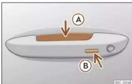
Fig. 78 Door handle: sensor surfaces
>>> Fig. 78
Ⓐ Unlocking sensor surface on the inside of the door handle.
B Locking sensor surface on the outside of the door handle.
Depending on the equipment, the vehicle may have the Keyless Access system.
Configure the Keyless Access system
The behaviour of the Keyless Access system can be adjusted in the Vehicle settings menu of the Infotainment system.
If the Keyless Access function is disabled, its operation is limited.
Keyless Access is a key-free locking and ignition system to unlock and lock the vehicle without actively using its key. For this, it is only necessary that there is a valid vehicle key in the detection area corresponding to the attempted access to the vehicle.
Unlock the vehicle
- Touch the surface of the sensor located inside the handle Ⓐ. All turn signals will flash twice.
If the sensor surface is touched twice, the entire vehicle will unlock.
Automatic vehicle unlock
The vehicle can be unlocked automatically. To do this, the function must be activated in the Infotainment system and the vehicle key must be in the proximity zone of the vehicle.
If the key is in the proximity zone, the vehicle is automatically unlocked.
If the vehicle is not unlocked for an extended period, the function is deactivated.
The vehicle can be unlocked and locked via the front doors only. When doing so, the remote control key must be no further than approx. 1.5 m away from the door handle.
It does not matter where you carry the key, e.g. in your jacket pocket.
Once the doors have been locked, they cannot be opened again immediately. This will enable you to check that the doors are properly closed.
If you wish you may unlock only the corresponding door or the entire vehicle. The necessary adjustments can be performed in vehicles with a driver information system >> page 89.
General information
If a valid key is in the proximity of the car >> Fig. 77, the Keyless Access locking and starting system gives the key entry as soon as one of the sensor surfaces on the front door handles is touched.
The following features are then available without having to use the vehicle key actively:
• Keyless Entry: unlocking the vehicle using the handles of the front doors or the soft-touch/handle on the rear lid.
Opening and closing
• Keyless Exit: locking the vehicle using the sensor of the driver or passenger door handle.
- Easy Open: opening the rear lid moving one foot below the rear bumper >> page 109.
- Press & Drive: keyless starting of the engine with the starter button»»page 207.
The central locking and locking systems operate in the same way as a normal locking and unlocking system. Only the controls change.
Unlocking the vehicle is confirmed with a double flash of the indicator lights; locking by a single flash.
If the vehicle is locked and then all doors and the rear lid are closed leaving the last key used inside the vehicle and none outside, the vehicle will not lock immediately. All the vehicle's indicator lights will flash four times. The vehicle will lock after a few seconds if you do not open any door or the rear lid.
The vehicle will lock again after a few seconds if you unlock the vehicle but fail to open any door or boot hatch.
Unlocking and opening the doors (Keyless-Entry)
- Grip one of the front door handles. When you do this, you touch the sensor surface
Fig. 78 (arrow) of the handle and the vehicle unlocks.
- Open the door.
On vehicles with selective opening or info-tainment system configuration, pulling the door handle twice will unlock all doors.
In vehicles without the "Safe" security system: closing and locking the doors (Keyless-Exit)
- Switch the ignition off.
- Close the driver's door.
- Touch (once) the locking sensor surface
Fig. 78 (arrow) on one of the front door handles. The door that is used must be closed.
In vehicles with the "Safe" security system: closing and locking the doors (Keyless-Exit)
- Switch the ignition off.
- Close the driver's door.
- Touch (once) the sensor surface» Fig. 78 (B) (arrow) on one of the front door handles. The vehicle locks with the "Safe" security system» page 101. The door that is used must be closed.
- Touch (twice) the sensor surface»» Fig. 78 ⑧ (arrow) of one of the front door handles to lock the vehicle without activating the "Safelock" security system»» page 101.
Unlocking and locking the boot hatch
When the vehicle is locked, the rear lid automatically unlocks on opening if there is a valid vehicle key in the proximity zone
Fig. 77.
Open or close the rear lid normally.
After closing, the hatch locks automatically. If the complete vehicle is unlocked, the rear lid will not lock automatically after closing it.
What happens when locking the vehicle with a second key
If there is a vehicle key inside the vehicle and it is locked from the outside with a second vehicle key, the key inside the vehicle is blocked for engine ignition» page 207. In order to enable engine ignition, press the button on the key inside the vehicle.
Automatically disabling sensors
If the vehicle is not locked or unlocked for a long period of time, the proximity sensors on the passenger doors are automatically disabled.
If one of the sensor surfaces on the door handles is often activated in an unusual manner with the vehicle locked (e.g. by the branches of a bush rubbing against it), all proximity sensors are disabled for a certain period of time.
Sensors will again be enabled:
》
Operation
• After a time.
- OR: if the vehicle is unlocked with the button ⏻ on the key.
• OR: if the boot is opened.
- OR: if the vehicle is unlocked manually with the key.
Keyless Access temporary disconnection function
You can deactivate the vehicle's Keyless Access unlocking for one locking and un-locking cycle.
- Move the gear lever to position P since otherwise the vehicle cannot be locked.
- Close the door.
- Push the central locking button ☐ on the remote control and touch the locking sensor surface of the driver door handle
Fig. 78 B within the following 5 seconds. Do not grasp the door handle; otherwise the vehicle will not unlock. Deactivation is also possible if the vehicle is locked through the driver's door lock.
- To check that the function has been deactivated, wait at least 10 seconds, grip and pull on the door handle. The door should not open.
The next time the door can only be unlocked via the remote control or the lock cylinder.
The next time the door is locked/unlocked, Keyless Access will be active again.
Keyless Access permanent disconnection function
You can deactivate the vehicle unlock with Keyless Access permanently in the infotainment system so that others cannot unlock or start the vehicle.
Convenience functions
To close all the electric windows and the sunroof using the comfort function, keep a finger for a few seconds on the locking sensor surface»» Fig. 78 (arrow) of the door handle until the windows and roof have closed.
How the doors open when touching the sensor surface on the door handle will depend on the settings that have been activated in the infotainment system, using the function button > Vehicle > Exterior > Central locking.
CAUTION
The sensor surfaces on the door handles could engage if hit with a water jet or high pressure steam if there is a valid vehicle key in the proximity. If at least one of the electric windows is open and the sensor surface >> Fig. 78 (arrow) on one of the handles is activated continuously, all windows will close.
Note
- If the vehicle battery has little or no charge, or the vehicle key battery is almost or entirely out of charge, you will probably not be able to lock or unlock the vehicle with the Keyless Access system. The vehicle can be unlocked or locked manually » page 104.
-
To control the proper locking of the vehicle, the release function is disabled for approx. 2 seconds.
-
If the message Keyless access system faulty is displayed on the screen of the dash panel, abnormalities may occur in the operation of the Keyless Access system. Contact a specialised workshop. To do so, CUPRA recommends going to a specialised CUPRA dealer or any SEAT dealership.
- Depending on the function set on the infotainment system for the mirrors, the exterior mirrors will unfold and the surround lighting will come on when unlocking the vehicle using the sensor surface on the driver and passenger door handles »» page 125.
- If there is no valid key inside the vehicle or the system fails to detect one, a warning will display on the dash panel screen. This could happen if any other radio frequency signal interferes with the key signal (e.g. from a mobile device accessory) or if the key is covered by another object (e.g. an aluminium case).
Opening and closing
- If the sensors are very dirty, e.g. have a layer of salt, the correct functioning of the sensors on the door handles may be affected. In this case, clean the vehicle.
- If the vehicle is fitted with an automatic gearbox, the vehicle can only be locked by pressing the parking lock button P.
- To improve the safety of your vehicle, the remote control of the system is equipped with a position sensor. If this remote control does not detect movement for a certain length of time, the system will conclude that the vehicle cannot be opened (e.g. on a night table) so it will be disabled.
- If, when trying to block the vehicle, the last used key is still inside, all the turn signals will flash 4 times.
Locking system "Safe"1)
When the vehicle is blocked, the "Safe" security system puts the door handles out of operation and prevents unauthorised persons for entering. The doors cannot be opened from inside >>> △.
Depending on the vehicle, when switching the ignition off, a warning may be displayed on the control panel screen stating that the "Safe" security system is activated.
Lock the vehicle and activate the "Safe" security system.
- Press the locking button ☐ once on the vehicle key.
Lock the vehicle without activating the "Safe" system.
- Press the locking button on the vehicle key twice.
- OR: touch the sensor surface on the outside of the door handle twice>> Fig. 78 B.
When the "Safe" security system is disabled, the following needs to be taken into account:
- The vehicle can be unlocked and opened from the inside using an door handle.
• The anti-theft alarm is activated. - The vehicle interior monitoring system and the anti-tow system are disabled.
"Safe" status
The flashing frequency of the diode in the door sill immediately confirms the process. Initially, the diode flashes in a fast sequence for a brief period, then it stops for approximately 30 seconds and, lastly continues flashing slowly.

WARNING
Do not leave anyone (especially children) in the vehicle if it is locked from the outside and the "Safe" security system is activated, as the doors and windows cannot then be opened from the inside. Locked doors could delay assistance in an emergency.
Anti-theft alarm system
Description
The anti-theft alarm makes it more difficult to break into the vehicle or steal it. The system will initiate acoustic and optical warning signals when your vehicle is tried to be forced.
The anti-theft alarm is automatically turned on when the vehicle is locked with the key. The system is immediately activated and the turn signal light located on the driver door will flash along with the turn signals, indicating that the alarm and the locking security system (double lock) have been turned on.
If any of the doors or the bonnet are open, they will not be included in the protection zones of the vehicle when the alarm is connected. If the door or the bonnet are
》
Operation
subsequently closed, they will be automatically included in the protection areas of the vehicle and the turn signals will flash accordingly when the doors close.
• The turn signal light will flash twice on opening and deactivating the alarm.
- The turn signal light will flash once on closing and activating the alarm.
When does the system trigger an alarm?
The anti-theft alarm siren will be triggered for about 30 seconds alongside a sound and optical (flashing) warning signals and will be repeated about ten times when the vehicle is locked and the following unauthorised actions are attempted:
- Opening a door that is mechanically unlocked using the vehicle key without switching on the ignition in the next 15 seconds (in certain markets, such as the Netherlands, there is no 15 second waiting time and the alarm is activated immediately on opening the door).
• A door is opened.
- Opening the bonnet.
• The rear lid is opened.
- When the ignition is switched on with a non-authorised key.
• Undue manipulation of the alarm.
• Disconnection of the vehicle battery.
- Movement inside the vehicle (in vehicles with interior monitoring) page 103).
- When the vehicle is towed (in vehicles with anti-tow system»»page 103).
- When the vehicle is raised (in vehicles with anti-tow system»»page 103).
- When the vehicle is transported on a ferry or by rail (vehicles with an anti-tow system or vehicle interior monitoring» page 103).
- When a trailer connected to the anti-theft alarm system is disconnected.
How to turn OFF the alarm
- Unlock the vehicle with the unlock button of the key.
• OR: turn the ignition on with a valid key.
If the driver's door is unlocked mechanically using the key, the ignition must be turned on within 15 seconds of opening the door.
Otherwise, the alarm will trigger for 30 sec. and the ignition will be blocked.
CAUTION
If the anti-theft security system is switched off, the vehicle interior monitoring and the tow-away protection are automatically disconnected.
Note
• After 28 days, the indicator light will be switched off to prevent the battery from exhausting if the vehicle has been left parked for a long period of time. The alarm system remains activated.
- If, after the audible warning goes off, another monitored area is accessed (e.g. the rear lid is opened after a door has been opened), the alarm is triggered again.
- The anti-theft alarm is not activated when the vehicle is locked from within using the central locking button.
- If the driver door is unlocked mechanically with the key, only the driver door is unlocked, the rest of the doors remain locked. Only when the ignition has been turned on will the other doors be available - but not unlocked - and the central locking button will be activated.
- If the vehicle battery is run down or flat then the anti-theft alarm will not operate correctly.
- Vehicle monitoring remains active even if the battery is disconnected or not working for any reason.
- The alarm is triggered immediately if one of the battery cables is disconnected while the alarm system is active.
Opening and closing
Interior monitoring and the anti-tow system
It is a monitoring or control function incorporated in the anti-theft alarm which detects unauthorised vehicle entry by means of ultrasound.
The vehicle interior monitoring and anti-tow sensor (tilt sensor) are automatically switched on when the anti-theft alarm is switched on. In order to activate it, all the doors and the rear lid must be closed.
If the "Safe">>> page 101 security system is switched off, the vehicle interior monitoring and the tow-away protection are automatically disconnected.
Activation
- It is automatically switched on when the anti-theft alarm is activated.
Deactivation
- Open the vehicle with the key, either mechanically or by pressing the button on the remote control. The time period from when the door is opened until the ignition is turned on should not exceed 15 seconds, otherwise the alarm will be triggered.
- Press the button on the remote control twice. The volumetric sensor and tilt sensors will be deactivated. The alarm system remains activated.
The vehicle interior monitoring and the anti-tow system are automatically switched on again next time the vehicle is locked.
If you wish to switch off the vehicle interior monitoring and the anti-tow system, it must be done each time that the vehicle is locked; if not, they will be automatically switched on.
The vehicle interior monitoring and the anti-tow system should be switched off if animals are left inside the locked vehicle (otherwise, their movements will trigger the alarm) or when, for example, the vehicle is transported or has to be towed with only one axle on the ground.
Deactivation through the infotainment system
- Turn off the ignition and press the function button > Vehicle > Exterior > Central locking > Interior monitoring.
- When the vehicle is locked now, the vehicle interior monitoring and the tow-away protection are switched off until the next time the door is opened.
False alarms
Interior monitoring will only operate correctly if the vehicle is completely closed. Please observe related legal requirements.
The following cases may cause a false alarm:
- Open windows (partially or fully).
- Panoramic/tilting sunroof open (partially or completely).
- Movement of objects inside the vehicle, such as loose papers, items hanging from the rear vision mirror (air fresheners), etc.
Note
- If the vehicle is relocked and the alarm is activated without the volumetric sensor function, relocking will activate the alarm with all its functions, except the volumetric sensor. This function is reactivated when the alarm is switched on again, unless it is deliberately switched off.
- If the alarm has been triggered by the volumetric sensor, this will be indicated by a flashing of the warning lamp on the driver door when the vehicle is opened. The flash is different to the flash indicating the alarm is activated.
- The vibration of a mobile phone left inside the vehicle may cause the vehicle interior monitoring alarm to trigger, as both sensors react to movements and shakes inside the vehicle.
- If on activating the alarm, any door or the rear lid is open, only the alarm will be activated. The vehicle interior monitoring and the anti-tow system will only be activated
Operation
once all the doors are closed (including the rear lid).
Doors
Introduction
The doors and rear lid can be locked manually and partially opened, for example if the key or the central locking is damaged.
WARNING
Opening and closing doors carelessly can cause serious injury.
- If the vehicle is locked from outside, the doors and windows cannot be opened from the inside.
- Never leave children or disabled people alone in the car. They could be trapped in the car in an emergency and will not be able to get themselves to safety.
- Depending on the time of the year, temperatures inside a locked and closed vehicle can be extremely high or extremely low resulting in serious injuries and illness or even death, particularly for young children.
WARNING
Getting in the way of the doors and the rear lid is dangerous and can lead to serious injury.
- Open and close the doors and the rear lid only when there is nobody in the way.
CAUTION
When opening and closing in an emergency, carefully disassemble components and then reassemble them carefully to avoid damage to the vehicle.
Emergency unlocking or locking of the driver's door

Fig. 79 Driver door handle: locking cylinder.
If the central locking system should fail to operate, the driver door can still be locked and unlocked by turning the key in the lock.
As a general rule, when the driver door is locked manually all other doors are locked. When it is unlocked manually, only the driver
door opens. Please observe the instructions relating to the anti-theft alarm system >> page 101.
- Remove the key blade from the vehicle key >> page 92.
- Insert the key blade into the lock cylinder to unlock or lock the vehicle.
Special characteristics
- The anti-theft alarm will remain active when vehicles are unlocked. However, the alarm will not be triggered» page 101.
• After the driver door is opened, you have 15 seconds to switch on the ignition. Once this time has elapsed, the alarm is triggered. - Switch the ignition on. The electronic immobilizer recognises a valid vehicle key and deactivates the anti-theft alarm system.
Note
The anti-theft alarm is not activated when the vehicle is locked manually using the key shaft»» page 95.
Opening and closing
Emergency lock of doors without lock cylinders
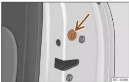
Fig. 80 Locking the door manually.
If the central locking system should fail to work at any time, doors with no lock cylinder will have to be locked separately.
The emergency lock is located on the front of the front passenger's door and the rear doors. It can only be seen if the door is open.
• Pull the cap out of the opening.
- Insert the key in the inside slot and turn it to the right as far as it will go (if the door is on the right side) or to the left (if the door is on the left side).
- Replace the cap.
Once the door has been closed it can no longer be opened from the outside. Pull the interior door handle once to unlock and open the door.
Childproof locks

Fig. 81 Childproof lock on the left hand side door.
The childproof lock prevents the rear doors from being opened from the inside. This system prevents minors from opening a door accidentally while the vehicle is running.
This function is independent of the vehicle electronic opening and locking systems. It only affects rear doors. It can only be activated and deactivated manually, as described below:
Activating the childproof lock
– Unlock the vehicle and open the door in which you wish to activate the childproof lock.
- With the door open, rotate the groove in the door using the ignition key, clockwise for the left hand side doors»» Fig. 81 and
anti-clockwise for the right hand side doors.
Deactivating the childproof lock
- Unlock the vehicle and open the door whose childproof lock you want to deactivate.
- With the door open, rotate the groove in the door using the ignition key, anti-clockwise for the left hand side doors»» Fig. 81 and clockwise for the right hand side doors.
Once the childproof lock is activated, the door can only be opened from the outside.
Rear lid
Introduction
The rear lid unlocks and locks together with the doors.
On vehicles with Keyless Access, the rear lid unlocks automatically when it is opened >> page 98.
WARNING
Careless and unsuitable locking, opening and closing of the rear lid can cause accidents and serious injury.
Operation
- The rear lid must not be opened when the reverse or rear fog lights are lit. This may damage the tail lights.
- Do not close the rear lid by pushing it down with your hand on the rear window. The glass could smash. Risk of injury!
- Ensure the rear lid is locked after closing it. If not, it may open unexpectedly while driving.
- Closing the rear lid without observing and ensuring it is clear could cause serious injury to you and to third parties. Make sure that no one is in the path of the rear lid.
- Never drive with the rear lid open or half-closed, exhaust gases may penetrate into the interior of the vehicle. Danger of poisoning!
- Never leave the vehicle unattended or allow children to play inside or next to it, especially if the rear lid is open. Children could enter the luggage compartment, close the rear lid and become trapped. A locked vehicle can reach extremely high and low temperatures, depending on the time of year, thus causing serious injuries, illness or even death.
CAUTION
Before opening or closing the rear lid, make sure that there is enough space to open or close it, e.g. when pulling a trailer or in a garage.
Note
Before closing the rear lid, make sure that the key has not been left inside the luggage compartment.
Opening and closing the rear lid

Fig. 82 Rear lid: opening from outside.
The rear lid opening system operates electrically. It is activated by exerting slight pressure on the handle>>Fig. 82.
To lock or unlock the rear lid, press the ≈ or 🔒 buttons of the vehicle key.
A warning appears on the instrument panel display if the rear lid is open or not properly closed. An audible warning is also given if it is opened while the vehicle is moving faster than 6 km/h (4 mph).
Opening and closing
- To open: place slight pressure on the handle. The rear lid opens automatically.
• To close: hold one of the handles on the inner trim and close it by moving it downwards, or press the button on the rear lid >> Fig. 83.
If the doors are locked, the rear lid is also locked.
Opening and closing
Rear lid with electric opening and closing

Fig. 83 Rear lid: button to close the rear lid.
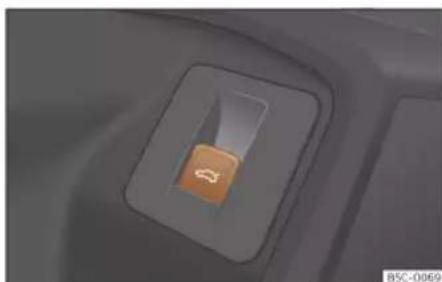
Fig. 84 On the driver's door: button to open and close the rear lid.
Opening the rear lid
- Unlock the vehicle»» page 95 and briefly press the handle of the rear lid. On vehicles with Keyless Access you can directly press the handle of the rear lid. The rear lid is un-
locked if an authorised key is recognised in the proximity of the vehicle.
- OR: depending on the features, pull the
- OR: press and hold the ≈ button of the vehicle key for approx. 1 second. If the vehicle is locked, only the rear lid is unlocked (the doors remain locked).
- OR: on vehicles with Keyless Access and sensor-controlled opening you can open the rear lid by moving one foot in the area of the sensors located below the rear bumper (Easy Open» page 109). The rear lid will be automatically opened.
Closing the rear lid
- Briefly press the ≈ button on the rear lid >> Fig. 83 >> △ in Introduction on page 105.
- OR: depending on the features, pull the button on the driver door upwards
Fig. 84.
-
OR: on vehicles with Keyless Access, press and hold the ≈ vehicle key button until the rear lid is closed, or move one foot into the area of the sensors located below the rear bumper (Easy Open)»»page 109. The vehicle key must be in the Keyless Access system detection zone at the rear outside the vehicle.
-
OR: manually move the rear lid in the direction of closing until it closes automatically.
- The rear lid goes down automatically to the final position and also closes automatically
△ in Introduction on page 105.
Interrupting opening or closing
After beginning to open or close the rear lid, the action can be halted by pressing one of the ⇌ buttons.
If you press one of the ≈ buttons again, the rear lid will move again in the original direction.
If the rear lid is met with resistance or an obstacle during the automatic opening or closing, opening or closing will be interrupted immediately. For the closing process, the rear lid opens again slightly.
- Check why it has not been possible to open or close the rear lid.
• Try to open or close the rear lid again. - If necessary, the rear lid can be opened or closed by hand using reasonable force.
Particular features if towing a trailer
If the factory-fitted towing bracket is electrically connected to a trailer»» page 291, the electric rear lid can only be opened or closed with the buttons on the rear lid itself or by using the Easy Open function.
》
Operation
Acoustic warnings
Throughout the process of opening or closing the rear lid, acoustic warnings can be heard. Exception: when the rear lid is opened manually using the handle or the Easy Open function with the movement of the foot or closed using the button on the rear lid itself >> Fig. 83.
Modifying and memorising the opening angle
If the space behind or above the vehicle is less than the travel area of the rear lid, you can change the opening angle of the rear lid.
To memorise a new opening angle, the rear lid must be open at least halfway.
- Interrupt the opening process in the desired position.
- Press the ≈ button» Fig. 83 on the rear lid for at least 3 seconds.
The opening angle is memorised. Memorisation is indicated by blinking of the hazard warning lights and an audible warning.
Resetting and memorising the opening angle
For the rear lid to reopen completely, the opening angle must be reset and memorised again.
- Release the rear lid and open it to the memorised height.
- Lift the rear lid by hand as far as it goes. To do this, some force will have to be used.
- Press the 📋 button » Fig. 83 on the rear lid for at least 3 seconds.
- This resets and memorises the factory-set opening angle. Memorisation is indicated by blinking of the hazard warning lights and an audible warning.
Automatic protection against overheating
If the system is operated repeatedly in a short space of time, it automatically switches off to prevent overheating.
Once the system is cool again, the function can be reused. Until then, the rear lid can only be opened and closed by hand using reasonable force.
If with the rear lid open the vehicle battery is disconnected» page 333 or the corresponding fuse burns out» page 58, the system will have to be reset. This requires closing the rear lid completely once.
Emergency unlocking
page 110
WARNING
If a lot of snow builds up on the rear lid or it is heavily loaded, the rear lid may not open
or, after opening, it may lower by itself due to the extra weight and cause serious in-jury.
- Do not open the rear lid when there is a lot of snow on it or when carrying a load (e.g. on a rack).
- Before opening the rear lid, remove the snow or the load.
Opening and closing
Rear lid with sensor-controlled opening and closing (Easy Open)

Fig. 85 Rear lid with sensor-controlled opening (Easy Open).

Fig. 86 Lower sensor detection area.
If there is a valid vehicle key in the proximity of the rear lid, it is possible to unlock and open or close it moving one foot in the area of the sensors located under the rear bumper.
- Switch the ignition off.
- Stand in front of the rear bumper, in the middle.
- With a brisk movement, bring your foot and lower leg as close as you can to the bumper. The lower part of the leg needs to be close to the upper sensor area and your foot must be close to the lower sensor area >> Fig. 85 ①.
- Quickly remove your foot and lower leg from the sensor areas» Fig. 85 ②. The rear lid will be automatically opened.
- If the rear lid fails to open, repeat the procedure after a few seconds. The detection zone of the lower sensor may not have been reached>> Fig. 86.
The rear lid can be closed with another foot movement similar to the opening one (provided a valid vehicle key is in the proximity of the rear lid).
When closed, the rear lid automatically locks if the vehicle has been locked beforehand and there is no valid key inside.
While the rear lid is in motion (either opening or closing), it can be stopped with another foot movement similar to the opening one (provided a valid vehicle key is in the proximity of the rear lid).
The Easy Open feature is not available or only has limited availability in the following situations (examples):
• If the rear bumper is very dirty.
• If the rear bumper is wet with salt water, e.g. after having driven on gritted roads.
- If the vehicle has been equipped at a later time with a tow bracket.
In the event of heavy rain, the Easy Open feature may take a little longer to open the boot or may deactivate automatically, to avoid the boot opening by accident, e.g. because of the running water.
The Easy Open function can be connected and disconnected permanently in the infotainment system using the button > Vehicle > Exterior > Central locking.
WARNING
If there is a valid key in the proximity of the rear lid, in some cases the Easy Open function may be accidentally activated and the rear lid will open, for example, when sweeping under the rear bumper, when directing a water jet or high pressure steam to the area or when carrying out maintenance work or repairs in that area. If accidentally opened, the rear lid could injure somebody situated in its area of operation or cause material damage.
• Therefore, always make sure that there is no unsupervised valid key in the area near the rear lid.
• Before carrying out any maintenance or repair work on the vehicle, always disable
Operation
the Easy Open feature via the infotainment system.
- Before washing the vehicle, always disable the Easy Open feature via the infotainment system.
- Before attaching a bicycle rack or a trailer,»» page 291, always disable the Easy Open feature via the infotainment system.
Emergency unlocking of the rear lid

Fig. 87 Detail of the luggage compartment: emergency unlocking
The rear lid can be unlocked from inside in the event of an emergency (e.g. no battery).
There is a groove in the luggage compartment allowing access to the emergency opening mechanism.
Unlocking the rear lid from inside the luggage compartment
• Using the key blade, break the pre-punched sheet push it out towards the inside of the luggage compartment.
- Insert the key blade into the slot and move the key in the direction of the arrow until the lock unlocks»» Fig. 87.
Window controls
Electrically opening and closing the windows
![graph TD A["1"] --> B["2"] B --> C["3"] C --> D["4"] D --> E["5"] E --> F["6"] style A fill:#f9f,stroke:#333 style B fill:#f9f,stroke:#333 style C fill:#f9f,stroke:#333 style D fill:#f9f,stroke:#333 style E fill:#f9f,stroke:#333 style F fill:#f9f,stroke:#333](/content/2026/07/1418883/images/ce0b223c010aac0b1eaa349a92b57691bfdb33689f6ede09120e51ee672ceff8.jpg)
Fig. 88 Detail of the driver's door: window controls.
- Opening the window: press the button
- Closing the window: pull the button
Buttons on the driver door
① Window on the front left door
② Window on the front right door
③ Window on the rear left door
④ Window on the rear right door
⑤ Safety switch for deactivating the electric window buttons in the rear doors.
The front and rear electric windows can be operated by using the controls on the driver door. The other doors each have a switch for their own window.
Always close the windows fully if you park the vehicle or leave it unattended»» △.
You can use the electric windows for approx. 10 minutes after switching off the ignition if neither the driver door nor the front passenger door have been opened.
Safety switch
The safety control» Fig. 88 5 on the driver door can be used to disable the electric window buttons on the rear doors.
Safety switch not pressed: buttons on rear doors are activated.
Safety switch pressed: buttons on rear doors are deactivated.
Opening and closing
The safety control symbol 📧 lights up in yellow if the buttons on the rear doors are switched off.
Convenience open/close function
The electric windows can be opened or closed from outside using the vehicle key:
Convenience opening:
- Press and hold the 🔊button on the remote control key until all the windows and the sun-roof have reached the desired position.
- OR: First unlock the vehicle using the button on the remote control key and then keep the key in the driver door lock until all the windows and the sunroof have reached the required position.
Convenience closing:
- Press and hold button □ on the remote control key until all the windows and the sun-roof are closed >> △.
- OR: Keep the key in the driver door in the "lock" position until all the windows and the sunroof are closed.
- OR using the Keyless Access system (only locking): Press and hold the locking sensor surface» Fig. 90 (arrow) on the door handle for several seconds to close the windows and the sunroof. If you release the sensor surface, the closing movement stops.
During convenience closing, first the windows and then the sliding sunroof will be closed.
In the infotainment system different settings can be adjusted using the function button > Vehicle > Exterior > Windows > Convenience opening.
One-touch opening and closing
The one-touch automatic opening and closing is used to open or close the windows completely. It will not be necessary to hold the button of the corresponding electric window.
For the automatic raising function: pull the button for the corresponding window upwards until it reaches the second position.
For the automatic lowering function: push the button for the corresponding window upwards until it reaches the second position.
Stop automatic movement: push or pull on the button of the corresponding window.
Resetting one-touch opening and closing
The one-touch opening and closing function is not active after the vehicle battery has been disconnected or is flat and will have to be reset.
- Pull the button of the corresponding window and hold it for one second in this position.
- Release the button and pull upwards and hold again. The one-touch function is now ready for operation.
The automatic one-touch electric windows can be reinitialised individually or several at a time.

WARNING
Observe the safety warnings»» in Introduction on page 104.
- Incorrect use of the electric windows can result in injury.
- Never close the rear lid without observing and ensuring it is clear, to do otherwise could cause serious injury to you and third parties. Make sure that no one is in the path of a window.
- If the ignition is switched on, the electric equipment could be activated with risk of injury, for example, in the electric windows.
- The doors can be locked using the remote control key. This could become an obstacle for assistance in an emergency situation.
• Therefore always take the key with you when you leave the vehicle. - The electric windows will work until the ignition has been switched off and one of the front doors has been opened.
- If necessary, use the safety switch to disable the rear electric windows. Make sure that they have been disabled.
Operation
- For safety reasons, you should only use the remote control open and close functions within about 2 metres of the vehicle. To avoid injuries, always keep an eye on the windows when pressing the button to close them. The windows stop moving as soon as the button is released.
Note
If the window is not able to close because it is stiff or because of an obstruction, the window will automatically open again » page 112. If this happens, check why the window could not be closed before attempting to close it again.
Window anti-trap function
The roll-back function reduces the risk of injury when the electric windows close.
- If a window is obstructed when closing automatically, the window stops at this point and lowers immediately >> △.
- Next, check why the window does not close before attempting it again.
- If you try within the following 10 seconds and the window closes again with difficulty or there is an obstruction, the automatic closing will stop working for 10 seconds.
-
If the window is still obstructed, the window will stop at this point.
-
If there is no obvious reason why the window cannot be closed, try to close it again by pulling the tab within ten seconds. The window closes with maximum force. The rollback function is now deactivated.
- If more than 10 seconds pass, the window will open fully when you operate one of the buttons. One-touch closing is reactivated.
WARNING
Observe the safety warnings»» in Electrically opening and closing the windows on page 111.
- The roll-back function does not prevent fingers or other parts of the body getting pinched against the window frame. Risk of accident.
Sunroof
Introduction
The sunroof consists of two glass parts. The rear part is fixed and cannot be opened. It also has a sun blind.
The sunroof only works when the ignition is switched on. Once the ignition has been switched off, you can still open or close the sunroof for a few minutes provided the driver door and the front passenger door are not opened.
WARNING
If the sunroof is used negligently or without paying due attention, it can cause serious injury.
- Open or close the sunroof and the sun blind only when no one is in their path of movement.
- Never leave any key inside the vehicle when exiting.
- Never leave a child or any other person who may need help in the vehicle, especially if they have access to the vehicle key. If using they key unattended, they could lock the vehicle, start the engine, switch on the ignition and activate the sunroof.
• After switching off, it is still possible to open or close the sunroof during a short space of time provided that neither the driver nor passenger door is opened.
CAUTION
- To prevent damage, during winter temperatures remove any ice or snow that might be on the car roof before opening the sunroof or adjusting the tilt position.
- Before leaving the vehicle or in case of rainfall, always close the sunroof. With the sunroof open or in a tilted position, water can enter the interior and can cause considerable damage to the electrical system. As a result, other damage can occur in the vehicle.
Opening and closing

Note
• Leaves and other loose objects that accumulate on the sunroof rails should be regularly cleaned away either by hand or with a vacuum.
- If the sunroof does not work correctly, the anti-trap function will not work either. Contact a specialised workshop.
Operating the sunroof

Fig. 89 On the interior roof lining: sunroof button.
Functional area 🙏 can be operated in two ways: sliding and pressing.
Sliding: The roof is opened or closed totally or partially.
Pressing: The roof is raised, opened or closed totally or partially. Press again to stop the automatic movement.
Raising, opening and closing the sunroof Opening the sunroof:
• Automatic movement: slide your finger back over the functional area
Fig. 89 A.
- Manual movement: slide back over the functional area and keep it there.
Closing the sunroof:
• Automatic movement: slide your finger forward over the functional area A.
- Manual movement: slide forward over the functional area and keep it there.
Raising the sunroof:
• The sunroof can only be raised if it is closed.
• Automatic movement: press briefly in the centre of the functional area ➕ B
Closing the sunroof when raised:
• Automatic movement: slide your finger forward over the functional area A or press briefly in the centre of the functional area B
Stop the automatic opening or closing movement:
- Press again on the functional area
Convenience function to open or close the sunroof

Fig. 90 Door handle: sensor surface.
The sunroof can be opened and closed with the convenience function, just like the windows.
Using the door lock
- Hold the key in the door lock of the driver door in either the unlocking or locking position to open or close the roof in the tilted position. Release the key to interrupt this function.
Using the remote control
- Keep the locking or unlocking button pressed to open or close the roof. If you release the button is the opening or closing will stop.
》
Operation
Using the Keyless Access system (only closing)
- Press and hold the locking sensor surface >> Fig. 90 (arrow) on the door handle to close the sunroof. If you release the sensor surface, the closing movement stops.
Anti-trap function of the panoramic sunroof and sunshade
The anti-trap function can reduce the risk of injury when closing the sunroof and the sun blind >> △. If the sunroof or sun blind encounter resistance or an obstacle when closing, they reopen immediately.
- Check why the sunroof or sun blind do not close.
- Try to close the sunroof or sun blind again.
- If the sunroof or sun blind cannot be closed due to an obstacle or some resistance, it stops at the corresponding position and then opens. For automatic closing, a new closing attempt might take place.
- If the sunroof or sun blind is still unable to close, close it without the anti-trap function.
Closing the sunroof without the anti-trap function
- Before approx. 5 seconds after activation of the anti-trap function, slide your finger
forward over the functional area Fig. 89 A and keep pressed until the sun-roof is fully closed.
- The sunroof closes without the anti-trap function intervening!
- If the sunroof will still not close, visit a specialised workshop.
WARNING
Closing the sunroof or sun blind without the anti-trap function can cause serious injuries.
• Always be careful when closing the sun-roof and sun blind.
- No person should ever remain in the way of the sunroof or sun blind, especially when closing without the anti-trap function.
- The anti-trap function does not prevent fingers or other parts of the body from becoming trapped against the roof frame and injuries occurring.
Lights
Vehicle lighting
Control lamps

It lights up
Driving light totally or partially faulty.
Fault in the cornering light system.

It lights up
Rear fog light switched on.

It lights up
Left or right turn signal.
The control lamp flashes twice as fast when a turn signal is faulty.
Hazard warning lights on»» page 120.

It lights up
Trailer turn signals

It lights up
Main beam on or flasher on»» page 116.

It lights up
The Light Assist system is on»» page 118.
Lights
Several warning and control lamps light up for a few seconds when the ignition is switched on, signalling that the function is being verified. They will switch off after a few seconds.

WARNING
Observe the safety warnings>>> in Control and warning lamps on page 84.
Lighting and visibility buttons

Fig. 91 Dash panel: lights control.
By clicking on the button ⚙ MODE you can select between (the corresponding indicator lights up):

Switching on the dipped beam headlights.
AUTO
Automatic control of dipped beam headlights and daytime running lights.
Switching on the side lights.
Additionally, the following light functions can be activated by pressing on the corresponding symbol.
When the function is activated, the corresponding symbol lights up. To deactivate it, you will need to press on the symbol again.
D
FRONT
Turning the front fog lights on or off
REAR
Turning the rear fog lights on or off.
MAX
Connecting or disconnecting the wind-screen demisting function»»page 150.
REAR
Connecting or disconnecting the heated rear window»» page 150.
The driver is personally responsible for the correct use and adjustment of the lights in all situations.
Automatic dipped beam headlight control AUTO
The automatic dipped beam control is merely intended as an aid and is not able to recognise all driving situations.
When the lamp AUTO is alight, the vehicle lights and the instrument panel and controls automatically switch on in the following situations >> ▲:
- The photo sensor detects darkness, for example, when driving through a tunnel. They switch off when adequate lighting is detected.
- The rain sensor detects rain and activates the wipers. They switch off when the wipers have not been activated for a few minutes.
Daytime running lights
The daytime running lights consist of individual lights, integrated in the front headlights.
The daytime running lights come on every time the ignition is switched on if the lamps are off or the lamp AUTO is alight, if the light sensor does not detect darkness. The day-light running lights turn off when the ignition is turned off.
When the lamp AUTO is alight, a light sensor automatically switches dipped beam on and off (including the control and instrument lighting) or the daytime running lights depending on the level of exterior lighting.
Motorway light
The motorway light is available on vehicles equipped with LED High lights.
The function is connected and disconnected via the corresponding Infotainment system menu.
Operation
- Activation: when going above 110 km/h (68 mph) for more than 10 seconds, the dipped beam raises slightly to increase the driver's visibility distance.
- Deactivation: when reducing the speed of the vehicle below 100 km/h (62 mph), the dipped beam immediately returns to its normal position.
Audible warnings to advise the driver that the lights have not been switched off
If the ignition is not connected and the driver door is open, an audible warning signal is heard in the following cases: this will remind you to turn the light off.
- When the parking light is on»»page 116.
- When the lamp ⇒ or C is on.
WARNING
If the road is not well lit and other road users cannot see the vehicle well enough or at all, accidents may occur.
- The automatic dipped beam control (AUTO) only switches on the dipped beam when there are changes in light conditions but not, for example, when it is foggy.
WARNING
The side lights or daytime running lights are not bright enough to illuminate the road
ahead and to ensure that other road users are able to see you.
• Always use your dipped beam head lights if it is raining or if visibility is poor.
- Never drive with daytime lights if the road is not well lit due to weather or lighting conditions.
WARNING
If the headlights are set too high and not used correctly, there is a risk of dazzling or distracting other road users. This could result in a serious accident.
• Always make sure that the headlights are correctly adjusted.
Note
- The legal requirements regarding the use of vehicle lights in each country must be observed.
- The dipped beam headlights will only work with the ignition on. The side lights come on automatically when the ignition is turned off.
- The rear fog light can dazzle drivers behind you. You should use the rear fog light only when visibility is very poor.
Turn signal and main beam lever

Fig. 92 Turn signal and main beam lever (depending on the version).
More the lever to the required position:
① Right turn light or right-hand parking light (ignition switched off).
② Left turn light or left-hand parking light (ignition switched off).
③ Turning main beam headlights on: control lamp ☐ lit up on the instrument panel.
④ The headlight flasher comes on while we pull the lever. Control lamp ID lit up.
Place the lever in rest position to turn off the corresponding function.
Convenience turn signals
When the ignition is switched on, move the lever as far as possible upwards or
Lights
downwards and release the lever. The turn signal will flash three times.
The convenience turn signals are activated and deactivated in the infotainment system using the function button ☐ > Vehicle > Exterior > Light > Convenience turn signals >> page 89.
In vehicles that do not have the corresponding menu, this function can be deactivated in a specialised workshop.
Parking light P
The parking lights will only work with the ignition off. If said light is on, an audible warning will sound while the driver door is open.
- Switch the ignition off.
- Move the turn signal lever up or down.
When the parking light is switched on, the front side light and the tail light on the corresponding side of the vehicle turn on.
Parking light on both sides
- Switch the ignition off.
- Press the button ⚙ MODE to select
- Lock the vehicle from the outside.
In doing so, only the side lights of both headlights light up, and additionally the tail lights will do so partially.
WARNING
Improper or lack of use of the turn signals, or forgetting to deactivate them can confuse other road users. This could result in a serious accident.
• Always give warning when you are going to change lane, overtake or when turning, activating the turn signal in good time.
- As soon as you have finished changing lane, overtaking or turning, switch the turn signal off.
WARNING
Incorrect use of the headlights may cause accidents and serious injury, as the main beam may distract or dazzle other drivers.
Note
- When you turn the ignition off without having turned the turn signals off, an acoustic signal sounds while the driver door is open. This is intended as a reminder to switch off the turn signal, unless you wish to leave the parking light on.
- If the convenience turn signals are operating (three flashes) and the other convenience turn signals are switched on, the active part stops flashing and only flashes once in the new part selected.
- The turn signal only works when the ignition is switched on. The hazard warning
lights also work when the ignition is switched off.
- If a trailer turn signal malfunctions, the control lamp will stop flashing (trailer turn signals) and the vehicle turn signal will flash at double speed.
- The main beam headlights can only be switched on if the dipped beam headlights are already on.
- In cold or damp weather conditions, the headlights, tail lights and turn signals may mist up inside temporarily. This is normal and in no way effects the useful life of the vehicle lighting system.
- The parking light does not activate automatically if the left- or right-hand turn signal is left on and the ignition is disconnected.
Main beam assist (Light Assist)
The main beam assist automatically prevents glare from vehicles moving in the opposite direction or ahead in the same direction. In addition, the main beam assist detects illuminated areas and disconnects the main beam headlight when passing, e.g. by populated areas.
Within its limitations, the assist system automatically connects or disconnects the main
Operation
beam headlight depending on the environmental and traffic conditions, as well as the speed >> △.
Switching the main beam assist on ⒺA
- Turn on the ignition and select the mode AUTO in the lights panel >>Fig. 91.
- From the base position, press the turn signal and main beam headlights lever forwards
Fig. 92 ③
When the main beam assistant is on, the indicator lamp lights up on the instrument cluster display.
Switching the main beam assist off≡A
- Disconnect the mode AUTO in the lights panel>>> Fig. 91.
- OR: while the main beam is on, pull the turn signal light and main beam headlights lever forwards»» Fig. 92 4.
- OR: push the turn signal and main beam headlight lever forwards to manually turn on the main beam. The main beam assist will then be deactivated.
System limitations
In the following cases, the main beam head-light must be switched off manually because the main beam assist will not disconnect it on time or disconnect it at all:
- On roads with insufficient lighting with very reflective signs
- If road users are insufficiently lit up, e.g. pedestrians or cyclists.
- On closed curves, when the traffic in the opposite direction is partially hidden, on pronounced slopes or inclinations.
- On roads with traffic in the opposite direction and with a central reservation barrier where the driver can see over it e.g. lorry drivers.
• In the event of fog, snow or heavy rain
• In the event of dust or sand storms - If the windscreen is damaged in the camera's field of vision.
- If the camera's field of vision is misted up, dirty or covered by a sticker, snow or ice.
- If the camera is damaged or if the power supply has been cut off.
WARNING
The convenience features of the main beam assist should not encourage the taking of risks. The system is not a replacement for driver concentration.
- You are always in control of the main beam and adapting it to the light, visibility and traffic conditions.
- It is possible that the main beam head-light control does not recognise all driving
situations and is limited under certain circumstances.
- When the field of vision of the camera is dirty, covered or damaged, operation of the main beam control may be affected. This also applies when changes are made to the vehicle lighting system, for example, if additional headlights are installed.
CAUTION
To avoid affecting the operation of the system, take the following points into consideration:
- Clean the field of vision of the camera regularly and make sure it is free of snow and ice.
- Do not cover the field of vision of the camera.
- Check that the windscreen is not damaged in the area of the field of vision of the camera.
Note
- The headlight flasher can be turned on and off manually at any time with the turn signal and main beam lever» page 116.
- If there are objects that radiate light in the camera's area of influence, e.g. a portable navigation system, this may affect the operation of the main beam assist system.
Lights
Fog lights with cornering light function
The cornering light function is an additional function to the dipped beam headlights to improve lighting of the side of the road when taking a sharp turn at low speed.
The cornering light function works when the dipped beam headlights are already on and it is activated when driving at speeds below approximately 40 km/h (25 mph).
- If the steering wheel is turned or the turn signal is switched on, the front fog light gradually turns on. After the turn, the cornering light function is gradually switched off.
- When engaging reverse gear, both front fog lights turn on.
"Coming home" and "Leaving home" function
The "Coming home" and "Leaving home" function lights up the vehicle's immediate proximity when getting into and out of it in the dark. When switched on, the front position and dipped beam lights, tail lights and license plate light come on.
The "Leaving Home" is controlled by a photosensor.
In the vehicle settings menu of the infotainment system you can adjust the duration of the light switch-off delay, and activate and deactivate the function.
Activating the "Coming Home" function
For vehicles with light and rain sensors.
- Turn off the vehicle and turn off the ignition with the lights in AUTO>>> page 115 mode.
- The automatic "Coming Home" function is only active when the light sensor detects darkness.
For vehicles without light and rain sensors.
- Switch the ignition off.
- Activate the headlight flashers for approximately 1 second.
When the driver door is opened, the "Coming Home" lighting comes on. The headlight turning off time counts from when the last door or rear lid are closed.
The "Coming Home" lighting turns off in the following cases:
• Automatically, once the headlight turning off time has elapsed.
- Automatically, when a vehicle door or the rear lid is still open 30 seconds after starting the engine.
- If the light panel lamps are off»» page 115.
- With the ignition is switched on.
Activating the "Leaving Home" function
- Unlock the vehicle using the remote control.
- The "Leaving Home" function is only activated when the lights are in AUTO mode and the light sensor detects darkness.
The "Leaving Home" lighting switches off in the following cases:
- Automatically, when the "Leaving Home" switch-on time ends (default 30 sec).
- When the vehicle is locked using the remote control.
- If the light panel lamps are off>>>page 115.
- With the ignition is switched on.
Note
To activate the "Coming Home" and "Leaving Home" functions, the AUTO lamp on the main switch of the lights should be on and the light sensor should detect darkness.
Operation
Hazard warning lights

Fig. 93 Dash panel: hazard warning lights switch
The hazard warning lights are used to draw the attention of other road users to your vehicle in emergencies.
If your vehicle breaks down:
- Park your vehicle at a safe distance from moving traffic.
- Press the button to switch on the hazard warning lights >>> △.
- Switch the ignition off.
- Apply the electronic parking brake.
- Engage 1st gear in vehicles with a manual gearbox, or press the parking lock button P in vehicles with automatic transmission.
-
Use the warning triangle to draw the attention of other road users to your vehicle.
-
Always take the vehicle key with you when you leave the vehicle.
All turn signals flash simultaneously when the hazard warning lights are switched on. The two turn signal turn signal lamps ↔ and the turn signal lamp in the switch will flash at the same time. The simultaneous hazard warning lights also work when the ignition is switched off.
Emergency braking warning
If the vehicle brakes suddenly and continuously at a speed of more than 80 km/h (50 mph), the brake light flashes several times per second to warn the vehicles driving behind. If you continue braking, the hazard warning lights will come on automatically when the vehicle comes to a standstill. They switch off automatically when the vehicle starts to move again.
WARNING
- The risk of an accident increases if your vehicle breaks down. Always use the hazard warning lights and a warning triangle to draw the attention of other road users to your stationary vehicle.
- Due to the high temperatures that the catalytic converter can reach, never park in an area where the catalytic converter could come into contact with highly inflammable materials, for example dry grass or spilt petrol. This could start a fire.
Note
- The battery will run down if the hazard warning lights are left on for a long time, even if the ignition is switched off.
- The use of the hazard warning lights described here is subject to the relevant statutory requirements.
Dynamic headlight range control
The headlight range is automatically adjusted according to the vehicle load status when they are switched on.
WARNING
Heavy objects in the vehicle may mean that the headlights dazzle and distract other drivers. This could result in a serious accident.
- Adjust the light beam to the vehicle load status so that it does not blind other drivers.
Driving abroad
The light beam of the dipped beam lights is asymmetric: the side of the road on which you are driving is lit more intensely.
When a car that is manufactured in a country that drives on the right travels to a country
Lights
that drives on the left (or vice versa), it is normally necessary to cover part of the headlight bulbs with stickers or to change the adjustment of the headlights to avoid dazzling other drivers.
In such cases, the regulations specify certain light values that must be complied with for designated points of the light distribution. This is known as "Tourist light".
The light distribution of the headlights allows the specific "tourist light" values to be met without the need for stickers or changes being made to the settings.
Note
"Tourist light" is only allowed temporarily. If you are planning a long stay in a country that drives on the other side, you should take the vehicle to an Authorised Technical Service to change the headlights.
Interior lights
Lighting of the instrument panel, displays and switches
Depending on the model, the lighting of the instrument cluster and controls can be adjusted in the infotainment system, using the function button □ > Vehicle > Interior > Infotainment>>> page 89.
With the ignition switched on and without switching on the lights, the lighting dims as the exterior light decreases. In some cases, e.g. when driving through a tunnel without the AUTO function active, the instrument panel lighting may even switch off. The objective of this function is to provide the driver with a visual indication that he or she should activate the dipped beam.
If your vehicle is equipped with a digital instrument cluster (Digital Cockpit), the following message will appear Turn on the lights on the instrument cluster.
Interior and reading lights

Fig. 94 Detail of roof lining: front lighting of the passenger compartment.

Turning the interior lights on or off.
OFF
Door contact connection. The interior lights come on automatically when you unlock the vehicle, open a door or disconnect the ignition. The light goes out a few seconds after closing all the doors, when locking the vehicle or connecting the ignition.
Reading light
The reading light is tactile, each lens is turned on and off individually by pressing in the respective central area. In addition, the intensity of the light can be adjusted according to the pressure exerted.
If you want to turn on the two lenses together you must press the symbol ☐ >> Fig. 94.
Glove compartment and luggage compartment lighting
When opening and closing the glove compartment on the front passenger side and the rear lid, the respective light will automatically switch on and off.
Footwell lighting
The lights in the footwell area below the dash (driver and front passenger sides) will switch on when the doors are opened and will decrease in intensity while driving. This intensity can be adjusted through the infotainment system menu using the function button > Background lighting>> page 89).
Operation

Note
The reading lights go out when the vehicle is closed and locked or after a few minutes
of turning the ignition off. This prevents the battery from discharging.
Background lighting

Fig. 95 Schematic representation: Background lighting
The background lighting lights up the area of the centre console, the footwell area and, depending on the version, the front door panels and the instrument panel line.
There are predefined Background Lighting versions>>> Fig. 95. The intensity of the lighting can be adjusted using the function button ⚙:
• Automatic: lights up the interior of the vehicle depending on the selected driving mode.
- Manual: to adjust the intensity of the background lighting in each of the areas as well as to change the colour in the versions that have lighting on the front door panel and the instrument panel line.
• Off: turns off the background lighting.
Additional functions of the background lighting
• Door open alert: Representation on the line of the respective front door if the vehicle
reaches 10 km/h while either of the two front doors is not closed properly.
- Rear windows locked alert: Representation on the line of the respective front door when the operation buttons of the rear windows are pressed, if they have been locked with the safety button» Fig. 88 5 and the vehicle is locked (Auto Lock).
• Representation of the hazard warning lights: Animation on the entire background
Visibility
lighting line while the hazard warning light function is active.
- Representation of acceleration: Animation on the entire background lighting line when accelerating. This function is only represented in the Cupra when the link between the background lighting and the drive profile is activated.
The representation of these functions by the background lighting can be switched on and off both individually and as a whole in the infotainment system: □ > Background lighting > ⚙️ Settings.
Visibility
Windscreen wiper and rear window wiper systems
Window washer lever

Fig. 96 Operating the windscreen wiper and rear wiper.
More the lever to the required position:
| 0 | OFF | Windscreen wipers off. |
| 1 | INT | Wiper intervals.Use control »» Fig. 96 A to set the interval (vehicles without rain sensor), or the sensitivity of the rain sensor. |
| 2 | LOW | Slow sweep adjustable by using control »» Fig. 96 A |
| 3 | HIGH | Fast sweep adjustable by using control »» Fig. 96 A |
More the lever to the required position:
| 4 | 1x | Short wipe. Brief press, short clean.Hold the lever down for more time to increase the wipe frequency. |
| 5 | Windscreen washer. The windscreen washer function is activated by pushing the lever towards the steering wheel,and the wipers operate simultaneously. | |
| 6 | Interval wipe for rear window. The wiper will wipe the window approximately every six seconds. | |
| 7 | The rear window wash function is activated by pressing the lever, and the rear wiper starts simultaneously. |
WARNING
In cold conditions you should not use the wash/wipe system unless you have warmed the windscreen with the heating and ventilation system. The windscreen washer fluid could otherwise freeze on the windscreen and obscure your view of the road.
CAUTION
If the ignition is switched off while the windscreen wipers are switched on, they complete their wipe and return to the rest position. When the ignition is switched back on, the windscreen wiper will continue to operate at the same wiping level. Ice,
Operation
snow and other obstacles on the wind- screen may damage the wiper and the windscreen wiper motor.
- If necessary, remove snow and ice from the windscreen wipers before starting your journey.
- Do not switch on the windscreen wipers if the windscreen is dry. Cleaning with the windscreen wipers while dry can cause damage.
- In icy conditions, always check that the wiper blades are not frozen to the glass before using the wipers. In cold weather, it may help to leave the vehicle parked with the wipers in service position >> page 50.

Note
- The windscreen and window wipers only function when the ignition is switched on and the bonnet or rear lid, respectively, are closed.
- The rear wiper is automatically switched on when the windscreen wiper is on and the car is in reverse gear.
Wiper functions
Windscreen wipers performance in different situations
- If you stop the vehicle with the windscreen wiper in position 1 or 2, it will automatically
change to a lower position speed. The set speed will be resumed when the vehicle pulls away.
- The air conditioner comes on for approximately 30 seconds in air recirculation mode when the windscreen washer is activated, to prevent the smell of the windscreen washer fluid entering the inside the vehicle.
- When wiping at intervals, the intervals vary according to the speed. The higher the vehicle speed the shorter the intervals.

Note
- The wiper will try to wipe away any obstacles that are on the windscreen. The wiper will stop moving if the obstacle blocks its path. Remove the obstacle and switch the wiper back on again.
- The windscreen will be wiped again approximately 5 seconds after the windscreen washer has been activated, provided the vehicle is moving ("drip" function). If you activate the wipers less than 10 seconds after the "drip" function, a new wash sequence will begin without performing the last wipe. For the "drip" function to work again, you have to turn the ignition off and then on again.
Rain sensor

Fig. 97 Wiper lever: adjust the rain sensor

Fig. 98 Rain sensor sensitive surface
The rain sensor controls the frequency of the windscreen wiper intervals, depending on the amount of rain >> △ The sensitivity of the rain sensor can be adjusted manually. Manual wipe >> page 123.
Visibility
Move the lever to the required position
Fig. 97:
① Rain sensor off.
① Rain sensor on; automatic wipe if necessary.
A Setting sensitivity level of rain sensor
- Set control to the right: high sensitivity.
- Set control to the left: low sensitivity.
When the ignition is switched off and then back on, the rain sensor remains active and starts operating again when the windscreen wipers are in position ① and the vehicle is travelling at more than 16 km/h (10 mph).
Modified behaviour of the rain sensor
Possible causes of faults and mistaken readings on the sensitive surface >> Fig. 98 of the rain sensor include:
- Damaged wipers: a film of water on the damaged blades may lengthen the activation time, reduce the washing intervals or result in a fast and continuous wipe.
- Insects: insects on the sensor may trigger the windscreen wiper.
- Salt on the road: in winter, salt spread on the roads may cause an excessively long wipe when the windscreen is almost dry.
- Dirt: dry dust, wax, coating on glass (Lotus effect) or traces of detergent (car wash) may
reduce the effectiveness of the rain sensor or make it react more slowly, later or not at all.
- Windscreen crack: the impact of a stone will trigger a single wipe cycle with the rain sensor on. Next the rain sensor detects the reduction in the sensitive surface area and adapts accordingly. The behaviour of the sensor will vary with the size of the damage caused by the stone.
WARNING
The rain sensor may not detect enough rain to switch on the wipers.
- If necessary, switch on the wipers manually when water on the windscreen obstructs visibility.
Note
- Regularly clean the sensitive surface of the rain sensor>> Fig. 98 (arrow) and check for possible damage to the wiper blades.
- To remove wax and coatings, we recommend a window cleaner containing alcohol.
- Do not put stickers on the windscreen in front of the rain sensor. This may cause sensor disruption or faults.
Mirrors
Interior mirror anti-dazzle function
Rear view mirror with automatic anti-dazzle function
The anti-dazzle function is activated every time the ignition is switched on.
When the anti-dazzle function is enabled, the interior rear vision mirror will darken automatically according to the amount of light it receives. The anti-dazzle function is cancelled if reverse gear is engaged.
WARNING
In the event that an automatic anti-dazzle rear vision mirror breaks, an electrolyte fluid may leak. This could cause irritation to the skin, eyes and respiratory organs. If you come into contact with this liquid, it must be rinsed with large quantities of water. If necessary, get medial help.
CAUTION
In the event that an automatic anti-dazzle rear vision mirror breaks, an electrolyte fluid may leak. This liquid attacks plastic surfaces. Clean it with a wet sponge as soon as possible.
Operation
Note
- If the light falling on the interior mirror is obstructed (e.g. with the sun blind), the anti-dazzle mirror with automatic adjustment will not operate perfectly.
- When the interior lights are on or reverse gear engaged, the mirrors do not darken with automatic adjustment for anti-dazzle position.
- If you have to stick any type of sticker on the windscreen, do not do so in front of the sensors. Doing so could prevent the anti-dazzle function from working well or even from working at all.
Adjusting the exterior mirrors
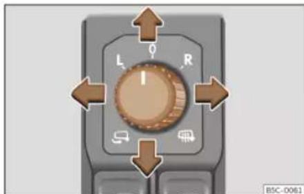
Fig. 99 Detail of the driver's door: control for the exterior mirror.
Turn the control to the corresponding position:
L/R Turning the knob to the desired position, adjust the mirrors on the driver side (L, left) and the passenger side (R, right) to the direction desired.
Depending on the equipment fitted on the vehicle, the mirrors may be heated according to the outside temperature.
Folding in mirrors.
Synchronized regulation of the exterior mirrors
In the infotainment system, the function button ☐ > Vehicle > Exterior > Mirrors can be used to select the exterior mirrors for synchronised adjustment.
- Turn the knob to position L1) .
- Adjust the left-hand exterior mirror. The right exterior mirror will be adjusted at the same time (synchronised).
- If necessary, correct the right-hand rear-view mirror: rotate the control to position 1 .
Tilt function for front passenger exterior mirror
When parking backwards, and in order to be able to see the kerb, the passenger side mirror can be automatically tilted towards the passenger to provide a better view of the kerb. The control must be in the position R1) for this feature to be operational.
The mirror returns to its original position as soon as you drive forward at over 15 km/h (9 mph) or switch off the ignition. It also returns to its original position if the position of the control is adjusted.
Visibility
Storing the rear view mirror settings for the tilt function
- Switch the ignition on.
- In the infotainment system, select > Vehicle > Exterior > Mirrors >> page 89.
- Select the R1) position on the control.
- Select reverse gear.
- Adjust the front passenger exterior mirror so that you can see, for example, the kerb area well.
- Release the reverse gear.
- The adjusted position for the rear view mirror is stored.
Fold the rearview mirrors when locking the vehicle
In the infotainment system, using the function button > Vehicle > Exterior > Mirrors the exterior mirrors can be selected to fold in when the vehicle is parked and locked >> page 89.
When the vehicle is locked with the remote control, the exterior mirrors are retracted automatically. When the vehicle is opened with the remote control, the exterior mirrors are deployed automatically.
WARNING
Convex or wide-angle exterior mirrors give a larger field of vision. However, they make objects look smaller and further away than they really are. If you use these mirrors to estimate the distance to vehicles behind you when changing lane, you could mis-judge the distance. Risk of accident!
WARNING
Fold and unfold the exterior mirror, taking care to avoid injuries.
- Only fold or unfold the exterior mirror when there is no-one in the way of the mirror.
- When moving the mirror, take care not to trap fingers between the mirror and the mirror bracket.
CAUTION
- If for any reason (e.g. a bump when manoeuvring) one of the rear view mirrors is knocked out of position, the mirrors must first be fully retracted with the electric control. The rear view mirror must not be placed by hand in the starting position, as the folding mechanism can be damaged.
- Before washing the vehicle in an automatic car wash, please make sure to fold
the exterior mirrors in to prevent them from being damaged. Electrically retractable exterior mirrors must not be folded in or out by hand, always use the electrical power control.
Note
- If the electrical adjustment should fail to operate, both of the mirrors can be adjusted by hand by lightly pressing the edge of the mirror glass.
- The fold-in function on the exterior mirrors will not activate at speeds over 40 km/h (25 mph).
Operation
Sun protection
sun blind

Fig. 100 Sun visor
Options for adjusting driver and front passenger sun visors
- Lower the sun visor towards the wind-screen.
- The sun visor can be pulled out of its mounting and turned towards the door >> Fig. 100 ①.
- Swing the sun visor towards the door, longitudinally backwards.
There is a vanity mirror on the sun visor, with a cover. When the cover is opened ② a light comes on.
The lamp goes out when the vanity mirror cover is closed or the sun visor is pushed back up.
WARNING
Folded sun blinds can reduce visibility.
• Always store sun blinds and visors in their housing when not in use.
i Note
The light above the sun visor automatically switches off after a few minutes in certain conditions. This prevents the battery from discharging.
Seats and headrests
Adjusting seats
Manual adjustment of the front seats

Fig. 101 Front seats: manual seat settings.
① Forwards/backwards: pull the lever and move the seat. The seat must engage when the lever is released!
② Raise/lower: pull the lever up or push down (several times if necessary) from its home position.
③ Tilting the backrest: turn the hand wheel.
④ Lumbar support: move the lever until the required position is achieved.
Seats and headrests

WARNING
Incorrect seat adjustment may lead to accidents and severe injuries.
- Only adjust the seats when the vehicle is stationary, as the seats could move unexpectedly while the vehicle is in motion and you could lose control of the vehicle. Furthermore, an incorrect position is adopted when adjusting the seat.
- Adjust the height, position and inclination of the front seats only when their movement area is empty.
• Make sure there are no objects in that area.
• Make sure that the movement and locking areas of the seats are clean.

WARNING
Incorrectly using upholstery and seat covers might cause an accidental activation of the electrical seat adjustment system and make it move unexpectedly while driving. This might cause loss of control of the vehicle and thus accidents or injuries. Moreover, the electrical components of the front seats might be damaged.
- Never attach or place seat upholstery or covers on the electric controls.
- Never use upholstery or seat covers that have not been explicitly authorised for the seats of the vehicle.
Electric driver's seat adjustment
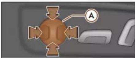

Fig. 102 Driver's seat: electric seat settings.
(A) Adjust the lumbar support: press the button according to the desired position.
⑧ Seat forwards/backwards: press the button forwards/backwards.
Seat up/down: Press the rear part of the button up/down. To adjust the angle of the seat cushion, press the front of the button up/down.
Backrest further upright/further reclined: press the button forwards/backwards.
The position will be saved automatically in the CUPRA Connect Active user when the ignition is switched off.

WARNING
- If the electric front seats are used negligently or without paying due attention, it can cause serious injury.
- The front seats can also be electrically adjusted when the ignition is switched off. Never leave a child or any other person who may need help in the vehicle.
• In the event of an emergency, electrical adjustment can be stopped by pressing any control.

CAUTION
To avoid damaging the electrical components of the front seats, please refrain from kneeling on the seat or applying sharp pressure at a single point to the seat cushion and backrest.

Note
- It may not be possible to electrically adjust the seat if the vehicle battery is very low.
- If the engine is started while the seats are being electrically adjusted, the adjustment will stop.
- When changing user a warning will be shown on the infotainment system's screen during the time that the seat is moving to the saved position. This movement can be stopped by pressing the stop button on the screen.
Operation
Headrest
Introduction
The possibilities for the adjustment and disassembly of the headrests are described below. Always make sure that the seats are correctly adjusted»»page 13.
All seats are equipped with a headrest. The central rear headrest is only intended for the central seat of the rear bench. Therefore, do not install it on any other seat.
Correct adjustment of headrest
Adjust the headrest so that its upper edge is at the same level as the top of your head and under no circumstances below eye level. Keep the back of your head always as close to the headrest as possible.
Adjusting the headrest for short people
Lower the headrest completely, even if your head is below its upper edge. In the lowest position, there may be a small distance between the headrest and the backrest.
Adjusting the headrest for tall people
Push the headrest up as far as it will go.
WARNING
If travelling with the headrests removed or improperly adjusted, the risk of severe or fatal injuries in the event of accidents and sudden braking or manoeuvres increases.
• Always travel with the headrest correctly installed and adjusted.
• To decrease the risk of cervical injuries in the event of an accident, adjust the head-rest correctly based on your height, always making sure that its upper edge is at the same height as the top of the head, but never below eye level. Keep the back of your head always as close to the headrest as possible and centred.
- Never adjust the headrest while the vehicle is in motion.
- Under no circumstances should the rear passengers travel while the headrests are in the non-use position.
CAUTION
When assembling and disassembling the headrests, do not let them meet the top lining of the vehicle, the back rest of the front seat or other parts of the vehicles. If not, this could damage the vehicle.
Adjusting the headrests

Fig. 103 Front seat: headrest adjustment.

Fig. 104 Rear headrest: headrest adjustment.
Adjusting the height of the headrests
- Grab the sides of the headrests with both hands and push upwards to the desired position. To lower it, repeat the same action, pressing the ①>>> Fig. 103>>> Fig. 104 button on the side.
Seats and headrests
• The headrest must lock correctly in one position.
Removing and fitting the headrests

Fig. 105 Rear headrest: removal.
Removing and fitting the front headrests
- Move the headrest upwards until it arrives to the top.
- Press the side button>>> Fig. 103 ① and remove the headrest.
• To refit, insert the headrest into the holes in the backrest, pushing it down until it engages.
Removing the rear headrests
To remove the headrest, the corresponding backrest must be partially folded forward.
- Unlock the backrest >> page 132.
- Move the headrest upwards until it arrives to the top.
- Press button>> Fig. 105 ①, while simultaneously pressing on the security hole ② with a flat screwdriver a maximum of 5 mm wide, and remove the headrest.
- Move the backrest until it engages properly
△ in Folding down and raising the rear seat backrest on page 133.
Fitting the rear headrests
To mount the external headrests, the corresponding backrest must be partially folded forward.
- Unlock the backrest >> page 132.
- Insert the headrest bars into the guides until they perceptibly engage. It should not be possible to remove the headrest from the backrest.
- Move the backrest until it engages properly
△ in Folding down and raising the rear seat backrest on page 133.
WARNING
Remove the rear headrests only when it is necessary to fit a child seat. After removing a child seat, refit the headrest immediately.
Seat functions
Memory function

Fig. 106 On the outer side of the driver's seat: memory buttons.
Memory buttons
The memory buttons can be used to save and turn on settings for the driver seat and the exterior mirrors.
Save the settings of the driver seat and the exterior mirrors while driving forward
• Apply the electronic parking brake.
- Move the gearshift to the neutral position.
- Switch the ignition on.
- Adjust the driver seat and the exterior mirrors.
- Press SET for longer than 1 second
Fig. 106.
- Press the memory button in which to store the settings within approx. 10 seconds. A »
Operation
warning sound will confirm they have been stored.
Storing the passenger rear view mirror settings while driving in reverse
- Apply the electronic parking brake.
- Move the gearshift to the neutral position.
- Switch the ignition on.
- Press the required memory button.
- Select reverse gear.
- Adjust the front passenger exterior mirror so that you can see, for example, the kerb area well.
- The new position of the mirror will be stored automatically and allocated to the vehicle key that was used to unlock the vehicle.
Activating settings
- With the vehicle stopped and the ignition switched on, press and hold the corresponding memory button until the saved position is reached.
- OR: With the ignition switched off and the driver's door open, briefly press the corresponding button.
- The front passenger side exterior mirror automatically changes from the position stored for reversing as soon as the vehicle moves forward at a speed of at least 15 km/h (10 mph) or when the gear selection lever is
changed to a position other than R >> page 125.
Initialising the seat position memory
The position memory system must be restarted if, for example, the driver seat has been changed.
Restarting deletes all memories and assignments for the seat with position memory. The memory keys can then be programmed again.
- Open the driver door and do not get into the vehicle.
- Operating the seat settings from outside the vehicle.
- Move the angle of the seat backrest completely forwards.
- Release the control to set the angle and then press again until an audible warning is heard.

WARNING
Adjust the memory function only when the vehicle is stationary.

Note
If the driver door is opened approx. 10 minutes after the vehicle was unlocked or later, the driver seat and the exterior mirrors do not move automatically.
Folding down and raising the rear seat backrest

Fig. 107 Rear seat: clip to hold the seatbelt in place.

Fig. 108 Rear seat: folding the backrest.
The rear seat backrest is split and each part be lowered separately to extend the luggage compartment.
Seats and headrests
Folding the backrest forwards
- Place the side seat belts in the trim clip >> Fig. 107.
- Completely lower the rear headrests >> page 130.
- Press the unlock button>> Fig. 108 ① forwards and at the same time fold the backrest down. The rear seat backrest is not engaged when the red marking of the button ② is visible.
Converting the table to a seat
- Raise and lock in the back rest. The red marking on the tab ② should no longer be visible when the backrest is properly secured.
WARNING
Serious injuries can be caused if the rear seat backrest is lowered or lifted without due care and attention.
- Never lower or lift the rear seat backrest while driving.
- Do no trap or damage the seat belt when raising the rear seat backrest.
- When lowering or lifting the rear seat backrest, keep your hands, fingers, feet and other body parts out of its path.
- For the rear seat belts to offer the necessary protection all the parts of the rear backrest must be properly engaged. This is particularly important in the case of the
centre rear seat. If someone is seated in a seat whose backrest is not properly engaged they will fly forward, along with the backrest, during an accident or a sudden driving or braking manoeuvre.
- A red signal on the button ② warns that the backrest is not engaged. Always check that the red marking is not visible when the backrest is in the upright position.
- When the rear seat backrest is lowered or is not properly engaged nobody else can travel in the corresponding seats (not even a child).
CAUTION
Serious damage can be caused to the vehicle and other objects if the rear seat backrest is lowered or lifted without due care and attention.
- Before lowering the rear seat backrest, always adjust the front seats so that neither the head restraints nor the cushions of the rear backrest can hit them.
Unlock the seat backrest with the cord

Fig. 109 In the luggage compartment: levers to unlock the rear backrest.
• Lower the head restraint properly.
- Open the rear lid.
- Pull the remote release lever of the left part>> Fig. 109 ① or right part ② of the backrest in the direction of the arrow. The released part of the rear seat backrest is folded automatically down and forwards.
• If this occurs, close the rear lid.
The rear seat backrest is not engaged when the red marking of the button>>>Fig. 108 ② is visible.
Operation
Front centre armrest

Fig. 110 Front centre armrest
To raise the armrest, pull it fully up in the direction of the arrow» Fig. 110 up or step by step depending on the desired opening.
To lower the armrest, first lift it to its highest position. Then lower it down.
To move the armrest horizontally, move it forward» Fig. 110 or backward as much as possible in the direction of the corresponding arrow.
WARNING
The front centre armrest may obstruct the driver's arm movements, which could cause an accident and severe injuries.
- Keep the storage compartments of the centre armrest closed at all times while the vehicle is in motion.
- Never let anyone sit on the centre arm-rest while the vehicle is in motion, not even a child. This position is incorrect and may cause severe injuries.
Transport and practical equipment
Storing objects
Positioning the luggage and car-go
It is possible to carry objects and luggage in the vehicle, in a trailer» page 291 and on the roof» page 140. When doing so, please consider all legal provisions.
Placing luggage inside the vehicle safely
- Distribute the load in the vehicle as evenly as possible.
• Always place equipment and heavy objects in the boot»» - Position heavy items in the boot as far forward as possible.
- Take into account the maximum authorised weight per axle, as well as the maximum authorised weight of the vehicle » page 367.
- Secure the objects to the fastening rings of the boot using appropriate chains or belts » page 138.
• Also place small objects safely.
Transport and practical equipment
- Adapt tyre pressure to the load. Take into account the pressure adhesive of the tyres >> page 342.
- In vehicles equipped with tyre pressure control system, adjust to the new load status if necessary >> page 346.
WARNING
Loose or unsecured objects can cause serious injury in case of sudden manoeuvring or braking or in case of an accident. Particularly if the airbag hits them when deploying and they are thrown across the inside of the vehicle. Please observe the following rules to minimise the risk of injury:
- Place all objects inside the vehicle safely.
- Secure all objects, little and large.
- Place the objects in the cabin in such a way that they can never reach the airbag deployment areas while the vehicle is in motion.
- Keep the storage compartments closed at all times while the vehicle is in motion.
- Place the objects in such a way that they never force any occupant of the vehicle to sit in an incorrect position.
- When transporting objects that take up a seat, never let anyone use that seat.
- Never leave hard, sharp or heavy objects loose in open storage compartment of the vehicle, on the cover behind the rear seat or on the dashboard.
- Remove all hard, sharp or heavy objects from the fabrics and bags inside the cabin and store them safely.
WARNING
The transport of heavy object changes vehicle handling and increases braking distance. Heavy objects that are not properly placed or secured may cause loss of control of the vehicle and thus severe injuries.
- Never put too much load in the vehicle. Both the carrying capacity as well as the distribution of the load in the vehicle have effects on the driving behaviour and braking ability.
- When transporting heavy objects, the driving behaviour of the vehicle varies due to the displacement of the centre of gravity.
• Always distribute the load in the vehicle as evenly and horizontally as possible.
• Always place heavy objects in the boot before the rear axle and as far away from it as possible. - Objects in the luggage compartment that are unsecured could move suddenly and modify the handling of the vehicle.
- Adapt your speed and driving style at all times to suit visibility, weather, road and traffic conditions.
- Accelerate with particular care and caution.
- Avoid sudden braking and manoeuvres. - Brake earlier than usual.
WARNING
- Never leave your vehicle unattended, especially when the rear lid is open. Children could climb into the luggage compartment, closing the door behind them; they will be trapped and run the risk of death.
- Close and lock all the doors and the rear lid when you leave the vehicle. Before you lock the vehicle, make sure that there are no adults or children in the vehicle.
CAUTION
Electrical wires or, depending on the features, the antenna embedded into the rear windows could be damaged, even irreparably, if they are in contact with objects.
Note
Straps for securing the load to the fastening rings are commercially available from accessory shops.
Operation
Luggage compartment
Luggage compartment shelf

Fig. 111 In the luggage compartment: removing and fitting the shelf.

Fig. 112 In the luggage compartment: removing and fitting the shelf.
Removing
- Detach the cord loops»» Fig. 111 B from their hooks A.
- Remove the rear shelf from the side supports>>Fig. 112 by pulling it upwards and then take it out.
If necessary, the rear shelf can be stored under the luggage compartment double floor >> page 137.
Fitting
- Insert the cover horizontally so that the "recess" fits onto the axis of the supports
Fig. 112 and press down until it engages.
- Hook the loops>>> Fig. 111 Ⓑ to the rear lid.

WARNING
Animals, loose or unsecured or objects carried on the rear shelf can cause serious injury in case of sudden manoeuvring or braking or in case of an accident.
- Do not leave hard, sharp or heavy objects or in bags on the rear shelf.
- Never transport animals on the rear shelf.

CAUTION
- Before closing the rear lid, ensure that the rear shelf is correctly fitted.
• An overloaded luggage compartment could mean that the rear shelf is not correctly seated and it may be bent or damaged.
- If the luggage compartment is overloaded, remove the tray.

Note
Ensure that, when placing items of clothing on the luggage compartment cover, rear visibility is not reduced.
Transport and practical equipment
Store the rear shelf

Fig. 113 In the luggage compartment: covers for storing the rear shelf.
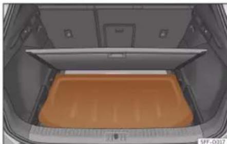
Fig. 114 In the luggage compartment: fitting the rear shelf.
Depending on the equipment, once the luggage compartment shelf has been removed, it can be stored under the boot floor.
- Remove the left and right covers
Fig. 113.
- Place the rear shelf in the corresponding housing>> Fig. 114. - Put the left and right covers in their original position.
Variable luggage compartment floor
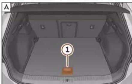

Fig. 115 Variable luggage compartment floor: A raised position; B lowered position.

Fig. 116 Variable luggage compartment floor: inclined position.
Variable floor in high position
- To move from the low position to the high position, lift the floor using the handle
Fig. 115 ① and pull it back until the front of the floor has fully passed the supports Fig. 115 ②.
- Move the floor forward over the supports as far as the rear seat backrest and then lower the floor with the handle ①
Variable floor in low position
• To move from the high position to the low position, lift the floor using the handle
Fig. 115 ① and pull it back until the front of the floor has fully passed the supports Fig. 115 ②
- Now let the front part fall to the floor and slide the floor forwards as far as the rear seat backrest; lower the floor at the same time with the handle ①
Operation
Variable floor in the tilted position
When the variable floor is tilted you can access the spare wheel or anti-puncture kit area.
- Lift the variable floor in the high position using handle >> Fig. 115 ①, pull it up and push it towards the backrest of the rear seats until it folds along the hinge line and the movable part of the floor is resting on itself.
- Rest the floor on its housings>>> Fig. 116 (arrows).
WARNING
- Always secure objects, even when the luggage compartment floor is properly lifted.
- Only objects that do not protrude more than 2/3 the height of the floor may be carried between the rear seat and the raised luggage compartment floor.
- Only objects that do not weigh than approximately 7.5 kg may be carried between the rear seat and the raised luggage compartment floor.
CAUTION
- The maximum weight that can be loaded on the luggage compartment variable floor in the top position is 100 kg.
- Do not let the luggage compartment floor fall when closing it. Always carefully
guide it downwards in a controlled manner. Otherwise, the lining and the floor of the luggage compartment could be damaged.
Fastening rings

Fig. 117 In the luggage compartment: fixed and deployable fastening rings.
There are fastening rings>>>Fig. 117 on the front and rear of the boot to secure loose objects and luggage with fastening belts and cords.
WARNING
If unsuitable or damaged belts or retaining straps are used, they could break in the event of braking or an accident. Objects could then be launched across the passenger compartment and cause serious or fatal injuries.
• Always use belts or straps that are suitable and in good condition.
- Tighten the belts and straps in a cross layout over the load placed on the boot floor and secure them to the fastening rings safely.
- Never exceed the maximum tensile load of the fastening rings when securing objects.
• Make sure that, particularly for flat objects, the upper edge of the load is higher than the fastening rings. - Depending on the features, take into account the instruction panels on the boot on how to place the load.
- Never secure a child seat to the fastening rings.
Note
- The maximum tensile load that the fastening rings can support is approx. 3.5 kN.
- Belts, straps and securing systems for the appropriate load can be obtained from specialised dealerships. To do so, CUPRA recommends going to a specialised CUPRA dealer or any SEAT dealership.
Transport and practical equipment
Net bag

Fig. 118 In the luggage compartment: net bag hooked up at floor level.
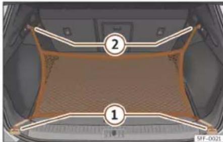
Fig. 119 In the luggage compartment: rings ① and hooks ② for attaching the net bag.
The luggage compartment prevents light luggage from moving. The net bag has a zip and can be used to store small objects.
The net bag can be hooked up to the luggage compartment in different ways.
Hooking the net bag into the luggage compartment floor
If necessary, the front eyes must be unfolded first» page 138.
- Secure the net hooks to the fastening rings ① and ② >> Fig. 118 >> ▲. The bag zip should be facing upwards.
Hook the net bag next to the load threshold
- Secure the short net hooks to the fastening rings» Fig. 119 ① »» △. The bag zip should be facing upwards.
- Secure the straps in the bag hooks ②.
Removing the net bag
The hooked up net bag is taut >> △.
- Release the net bag from the fastening rings.
- Store the net bag in the luggage compartment.
WARNING
To secure the elastic net bag on the fastening rings of the boot it must be stretched out. Once hooked up it is taut. If the net bag is hooked up or unhooked incorrectly the hooks could cause injuries.
• Always secure the bag hooks properly so that they do not suddenly release from the fastening rings when hooking or unhooking them.
- On hooking or unhooking them, protect your eyes and face in case the hooks are released suddenly.
• Always hook up the net bag hooks in the described order. If a hook is unfastened suddenly, this may cause injuries.
Bag hooks
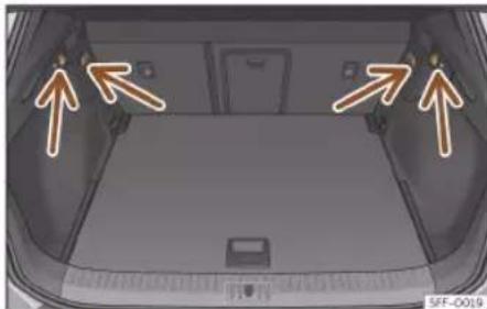
Fig. 120 In the luggage compartment: bag hooks.
There may be hooks for hanging bags on both sides of the luggage compartment >> Fig. 120.
The retaining hooks have been designed to secure light shopping bags.
Operation

WARNING
Never use the hooks to hang luggage or other objects. In case of sudden braking or an accident, the hooks could break.
Trapdoor for transporting long objects

Fig. 121 In the rear seat backrest: opening the trapdoor.

Fig. 122 In the luggage compartment: opening the trapdoor.
On the rear seat, behind the central armrest, there is a tailboard for transporting long items in the interior, such as skis.
To avoid soiling the interior, dirty objects should be wrapped (e.g. in a blanket) before they are inserted through the tailboard.
When the armrest is down, nobody may travel in the centre rear seat.
Opening the tailboard
• Lower the centre armrest.
- Pull the release lever in the direction of the arrow and push the tailboard cover
Fig. 121 ① down and forwards.
- Open the rear lid.
- Insert the long objects through the gap from the luggage compartment.
- Secure the objects with the seat belt.
- Close the rear lid.
Closing the tailboard
- Lift the tailboard cover until it engages. The red mark on the luggage compartment side should never be visible.
- Close the rear lid.
- Lift the centre armrest if necessary.

Note
The tailboard can also be opened from the luggage compartment. To do so, press the release lever down, in the direction of the arrow, and the cover upwards>> Fig. 122.
Roof carrier
Introduction
The vehicle roof has been designed to optimise aerodynamics. For this reason, cross bars or conventional roof carrier systems cannot be secured to the roof water drains.
As the roof water drains are integrated in the roof to reduce air resistance, only CUPRA-approved cross bars and roof carrier systems can be used.
Transport and practical equipment
Cases in which cross bars and the roof carrier system should be disassembled.
- When they are not used.
- When the vehicle is washed in a car wash.
- When the vehicle height exceeds the maximum height, for example, in some garages.
WARNING
• Always secure the load properly using belts or retaining straps that are suitable and in a good condition.
- Bulky, heavy, long or flat loads have a negative effect on aerodynamics, the centre of gravity and driving performance.
- Avoid sudden braking and manoeuvres.
- Adapt your speed and driving style at all times to suit visibility, weather, road and traffic conditions.
CAUTION
- Remove the cross bars and the roof carrier system before entering a car wash.
- Vehicle height is increased by the installation of cross bars or a roof carrier system and the load secured on them. For this purpose, check that your vehicle's height does not surpass the headspace limit, for example, for underpasses or for entering garage doors.
- Cross bars, the roof carrier system and the load secured on them should not inter-
fere with the roof aerial or hamper the path of the panoramic sun roof and the rear lid.
- On opening the rear lid make sure that it does not knock into the roof load.
For the sake of the environment
When cross bars and a roof carrier system are installed, the increased air resistance means that the vehicle uses more fuel.
Securing the crossbars and the roof carrier system

Fig. 123 Attachment points for the roof railings for the roof carrier system.
The crossbars are the basis of a series of special roof carrier systems. For safety reasons, special fixtures must be used to safely transport luggage, bicycles, skis, surf boards or boats on the roof. The appropriate accessories can be purchased at specialised CU-PRA dealers or any SEAT dealership.
Always secure the crossbars and the roof carrier system properly. Always take the assembly instructions that come with the crossbars and the roof carrier system in question into account.
The crossbars are assembled on the roof railings. The distance between crossbars >> Fig. 123 A should be between 70 and 90 cm and the distance between the crossbars and the brackets of the roof railings B must be 15 cm.
WARNING
Incorrect attachment and use of the crossbars and the roof carrier system may cause the whole system to detach from the roof and cause an accident and injuries.
• Always take the manufacturer assembly instructions into account.
- Check threaded joints and attachments travelling and if necessary tighten them after you have travelled a short distance. When making long trips, check the threaded joints whenever you stop for a rest.
- Do not modify or repair the crossbars or roof carrier system.
Operation
Note
Always read the assembly instructions that come with the crossbars and the roof carrier system carefully and keep them in the vehicle.
Loading the roof carrier system
The load can only be secured if the crossbars and the roof carrier system are properly installed >>> △.
Maximum authorised cargo on the roof
The maximum permissible roof load is 75 kg. This figure comes from the combined weight of the roof carrier, the cross bars and the load itself on the roof >> △.
Always check the weight of the roof carrier system, the cross bars and the weight of the load to be transported and weigh them if necessary. Never exceed the maximum authorised roof load.
If you are using cross bars and a roof carrier with a lower weight rating, you will not be able to carry the maximum authorised roof load. In this case, do not exceed the maximum weight limit for the roof carrier which is listed in the fitting instructions.
Distributing a load
Distribute loads uniformly and secure them correctly >> ⚠.
Check attachments
Once the cross bars and roof carrier system have been installed, check the bolted connections and attachments after a short journey and subsequently with a certain frequency.
WARNING
- Never exceed the maximum authorised load on the roof and on the axles or the vehicle's maximum authorised weight.
- Never exceed the load capacity of the cross bars and the roof carrier system, even if the maximum authorised roof load has not been reached.
- Secure heavy items as far forward as possible and distribute the vehicle load uniformly.
WARNING
If the load is loose or not secured, it could fall from the roof carrier system or cause accidents and injuries.
• Always use belts or retaining straps that are suitable and in a good condition.
Storage compartment
Introduction
Use the storage compartments only for small or light items.
WARNING
Objects inside the vehicle that are not secured could be thrown across the cabin in the event of sudden braking or manoeuvring. This may cause severe injuries as well as loss of control of the vehicle.
- Do not carry animals or sharp, hard or heavy items in open storage compartments of the vehicle, on the dashboard or on the cover behind the rear seats, or inside pieces of clothing or bags inside the vehicle.
- Keep the storage compartments closed at all times while the vehicle is in motion.
WARNING
Objects in the driver's footwell could difficult the use of the pedals. This may cause loss of control of the vehicle and increases the risk of severe injuries.
• Make sure that nothing prevents you from using the pedals at any time.
• Always secure the mat in the footwell.
- Never place other mats or other type of covers on the factory-fitted mat.
Transport and practical equipment
- Ensure that no objects can fall into the driver's footwell while the vehicle is in motion.
- When the vehicle is stationary, remove the objects in the footwell.
WARNING
If you leave lighters inside the vehicle, they might be damaged or lit inadvertently. This could lead to severe burns and damage to the vehicle.
- Before moving a seat, make sure there are no lighters in the moving part area of the vehicle.
- Before closing a storage compartment, make sure there are no lighters in the closing area.
- Never leave a lighter inside a storage compartment or any other surface of the vehicle as it could ignite due to the high temperatures on such surfaces, particularly during the summer.
CAUTION
- Do not store heat- or cold-sensitive objects, food or medicines in the cabin. Heat and cold could damage them or render them useless.
- Objects made from transparent materials left inside the vehicle, such as glasses, magnifying glasses or transparent suction
pads stuck to the windows can concentrate sunlight and damage the vehicle.
Glove compartment

Fig. 124 On the front passenger side: glove compartment.
Opening and closing the glove compartment
Opening: Pull the handle>>> Fig. 124 and open the glove compartment.
Closing: Press the glove compartment upwards.
WARNING
If the glove compartment is left open, the risk of causing severe injuries in the event of an accident, sudden braking or manoeuvring increases.
• Always keep the glove compartment closed while the vehicle is in motion.
Storage compartment under front seats
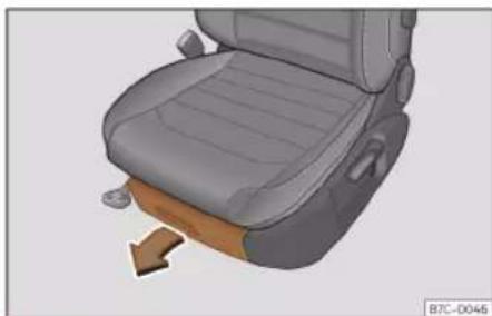
Fig. 125 Storage compartment under the front seats.
Opening: Press the tab on the drawer handle and take the drawer out.
Closing: Push the drawer under the seat until it engages.
Depending on the equipment, under the driver's seat there may be a magazine holder (about the size of the instruction manual) instead of the storage compartment.
Operation

WARNING
If the drawer is left open, it could prevent use of the pedals. This may cause serious accidents and injuries.
• Always keep the drawer closed while the vehicle is in motion. Otherwise, the drawer and any objects in it could fall into the driver's footwell and obstruct the pedals.

CAUTION
The drawer can contain 1.5 kg at most.
Drink holder

Fig. 126 In the rear central armrest: drinks holder.
The storage compartments of the driver and passenger doors contain a bottle holder.
Front drink holders
There are two cup holders in the centre console»» Fig. 126.
Drinks holder in the rear central armrest
Use: Lower the centre armrest.
When the drink holder is no longer in use, lift the armrest again.

WARNING
Incorrect use of the bottle holders may cause injuries.
- Never put hot drinks in the drink holders. In the event of sudden braking or an accident while driving, hot beverages in the bottle holders might spill and cause burns.
- Ensure that no bottles or other objects are dropped in the driver footwell while driving, as they could get under the pedals and obstruct their working.
- Never place glasses, food or other heavy objects drink holders. These heavy objects may be thrown across the cabin in the event of an accident and cause serious injuries.

WARNING
Closed bottles may explode inside the vehicle due to cold or heat.
- Never leave closed bottles in the vehicle if the temperature inside is very high or very low.

CAUTION
Do not leave open cans in the drink holders when the vehicle is in motion. If the drink is spilled (e.g. due to sudden braking) it may damage the vehicle and its electrical system.

Note
The inside elements of the drink holders can be extracted for cleaning.
Other object holders
You will find more object holders, compartments and supports in other parts of the vehicle:
• In the centre console.
- In the upper part of the glove compartment. The load of the compartment should not exceed 1.2 kg.
- Other storage compartments are found in the rear seat, to the left and the right of the seats.
There are hangers on the struts of the doors and the rear.
Transport and practical equipment

WARNING
Hanging clothes may decrease the driver's visibility, which may cause serious accidents and injuries.
• Always hang clothes from hangers in such a way that the driver's visibility is not affected.
- Only hang light pieces of clothing from the hangers of the vehicle. Never leave heavy, hard or sharp objects in the pockets of these pieces of clothing.
- Do not use clothes hangers to hang up the clothing, as this could interfere with the function of the head-protection airbags.
Power sockets
Vehicle power sockets

Fig. 127 12 volt power socket: ① inside the front armrest.
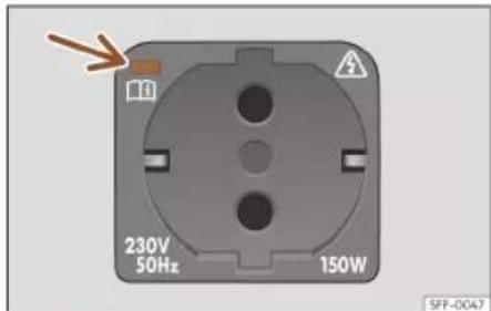
Fig. 128 On the right side of the luggage compartment: 230 volt power socket.
In the front armrest
- Lift the power socket cover>> Fig. 127.
- Insert the plug of the electrical appliance into the power socket.
USB power sockets
Depending on the equipment and the country, the vehicle may also have USB connections exclusively for charging or as a power socket.
These USB ports are located at the rear of the console, between the front seats. These connectors can work at a maximum power of up to 10.5 W per port.
They are not intended for file playback.
Maximum power consumption
| Power socket | Maximum power consumption |
| 12 Volts 120 Watts | |
| 230 Volts | 150 watts (300 watts - maximum 2 minutes) |
Electrical equipment can be connected to the 12 volt power socket.
Make sure that the maximum power consumption displayed on each outlet is not exceeded. The power consumption of devices is shown on the model plate.
When connecting two or more electrical devices at the same time, make sure that their total consumption never exceeds 190 watts >>> ①.
With the engine running, the power socket >> Fig. 128 activates automatically as soon as a connector is plugged in. If there is enough power available, the socket can still be used while the engine is off >> △
Connect an electrical device: Open the cover and insert the plug into the power socket as far as possible to unlock the built-in child lock. The socket only supplies power once the child lock is unlocked.
》
Operation
LED on the power socket
| Steady green light: | The childproof lock is unlocked. The socket is ready to operate. |
| Flashing green light: | The ignition is switched off, but there is enough power available to continue supplying the socket with current for a maximum of 10 minutes. If the connector is unplugged before this time elapses, the socket is disconnected and cannot be used again until the ignition is switched on again. |
| Flashing red light: | There is an anomaly, e.g. disconnection due to a current surge or overheating. |
Disconnection due to overheating
When the temperature exceeds a certain value, the 230 volt socket inverter is automatically disconnected. The disconnection prevents overheating when the power consumption of the connected devices is excessive or the ambient temperature is very high. The 230-volt power supply can be used once again after a cooling time. First unplug the connector of the connected device and then plug it back in again. This prevents the electrical device from being switched on again if this is not wanted.
WARNING
The electrical system is under high voltage!
- Do not spill liquids onto the socket.
- Do not plug adapters or extension cords into the 230 volt power socket. Otherwise, the integrated child lock will be unlocked and the power socket will operate.
- Do not insert conductive objects (a knitting needle, for example) into the 230 volt power socket.
WARNING
The power socket works only when the ignition is on. Improper use may cause serious injury or even fire. Children should therefore not be left in the vehicle unattended if the button is also left behind. Otherwise there is a possibility that they may be injured.
CAUTION
Always use the correct type of plugs to avoid damaging the sockets.
CAUTION
• 230 volt power socket:
- Do not leave devices or connectors that are too heavy (e.g. a transformer) hanging directly from the power socket.
- Do not connect neon lamps.
- Only connect devices to the socket if the device and socket voltage match.
- The built-in overload disconnect function prevents any electrical devices that require a high start-up current from turning on. In this case, unplug the electrical device's power supply and re-try the connection after about 10 seconds.
Note
- The use of electrical appliances with the engine switched off will cause a battery discharge.
- Should the connected appliance overheat, immediately switch it off and disconnect it from the socket.
- Before switching the ignition on or off, unplug the appliances from the USB ports to protect them from any damage caused by fluctuations in voltage.
- Some appliances may not work properly when connected to the 230 volt sockets due to a lack of power (watts).
Air conditioning
Air conditioning
Heating, ventilation and cooling
Introduction
The 3 zone Climatronic: heats, ventilates, cools and dehumidifies the passenger compartment considering it as 3 independent air conditioning areas (driver, front passenger and rear seats).
There are several ways to switch on the air conditioning:
- Press AUTO on the climabar >> Fig. 129 A
- OR: Press in the air conditioning menu >> page 150 or in the air conditioning widget.
- OR: Press in the air conditioning menu >> page 150 or in the air conditioning widget.
• OR: Change the desired temperature.
The Climatronic operates most effectively with the windows and the sunroof closed.
Some functions and menu tabs depend on the equipment.
Passenger recognition function
√ Valid for: hybrid vehicles.
The front or rear area passenger recognition function turns down the air conditioning in these areas if no occupation is detected in them, with the aim of reducing the vehicle's energy consumption.
The turning down of the air conditioning is indicated as follows:
- Front passenger area: on the front passenger temperature setting, which will display ECO instead of the selected temperature.
- Rear area: On the rear temperature setting, where ECO will be displayed instead of the selected temperature. This turning down of the air conditioning will also be displayed on the control located in the rear area.
Air conditioning percentage reached function
Shows how long it will take to reach the set comfort temperature as a percentage.
Once reached, 100% will be displayed on the screen. There is one indicator for the driver's area and another for the passenger area.
Dust and pollen filter
The dust and pollen filter with its activated charcoal cartridge serves as a barrier against impurities in the air taken into the vehicle interior.
The dust and pollen filter must be changed regularly so that air conditioner performance is not adversely affected.
If the filter loses efficiency prematurely due to use in areas with very high levels of air pollution, the filter must be changed more frequently than stated in the Service Schedule.

WARNING
Reduced visibility through the windows increases the risk of serious accidents.
- Always ensure that all windows are free of ice and snow, and that they are not fogged, so as to maintain good visibility of everything outside.
- Only drive when you have good visibility.
• Always ensure that you use the air conditioner and heated rear window to maintain good visibility. - Never leave the air recirculation on for a long period of time. If the cooling system is switched off and air recirculation mode switched on, the windows can mist over very quickly, considerably limiting visibility.
- Switch air recirculation mode off when it is not required.
»
Operation

WARNING
Stuffy or used air will increase fatigue and reduce driver concentration possibly resulting in a serious accident.
- Never leave the fresh air fan turned off or use the air recirculation for long periods of time; the air in the vehicle interior will not be refreshed.

CAUTION
• To replace the pollen filter, always visit a service centre.
- Switch the air conditioner off if you think it may be broken. This will avoid additional damage. Have the air conditioner checked by a specialised workshop.
- Repairs to the air conditioner require specialist knowledge and special tools. CU-PRA recommends going to a specialised CUPRA Service or SEAT Official Service.

Note
- When the cooling system is turned off, air coming from the outside will not be dried.
To prevent fogging of the windows, CUPRA recommends leaving the cooling system (compressor) turned on. To do this, press the function button A/C. The icon should light up. - The maximum heat output required to defrost windows as quickly as possible is
only available when the engine has reached its normal running temperature.
- Keep the air intake slots in front of the windscreen free of snow, ice and leaves to ensure heating and cooling are not impaired, and to prevent the windows from misting over.
- The air from the vents flows through the vehicle interior and is extracted by slots in the luggage compartment designed for this purpose. Therefore, you should avoid obstructing these slots with any kind of object.
- Do not smoke while air recirculation mode is on, as smoke drawn into the air conditioning system leaves residue on the evaporator, producing a permanent unpleasant odour.
- It is advisable to turn on the air conditioning at least once a month, to lubricate the system gaskets and prevent leaks. If a decrease in the cooling capacity is detected, a Technical Service should be consulted to check the system.
- When the engine is under extreme strain, switch off the compressor for a moment.
Air conditioning
Climatronic control

Fig. 129 Schematic representation: air conditioning functions
A Climabar
Fixed bar at the top of the Infotainment System>> Fig. 129 A screen, (even if it is disconnected) where the following Air Conditioning functions are located:

Shows fan status/speed. By pressing it, you can access the Air conditioning menu» page 150.

Access the seat heating submenu >> page 153.
Temperature Slide your finger from left to right or vice versa over the numbers to adjust the desired temperature. Press on the same numbers to access the temperature adjustment submenu.
Or: use the touch zones ① and ② (blue / red) to adjust the temperature of the Air Conditioning>> Fig. 129.

Switching air recirculation on and off >> page 152.
Temperature setting submenu
Submenu where the following functions are found:
⊕/⊖ Press to set the desired temperature on the driver or front passenger side. You can also slide your finger over the bar to make the adjustment.
SYNC Synchronizes the temperature on the driver's side with the other zones.
Operation
Air Conditioning Menu
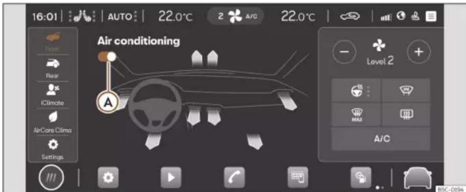
Fig. 130 Schematic representation: Air conditioning menu.
Within the Air Conditioning menu, the following submenus are found depending on the equipment:
Front Submenu
Submenu for the air conditioning in the front of the passenger compartment where the following functions are found:

Connect/disconnect the Climatronic >> Fig. 130 A.
Vents Selection of the air distribution to one or more of the following areas: feet, upper body or windscreen. The colour represented by the arrows does not indicate the outlet temperature of the air,
but the requested temperature depending on the surrounding conditions.

Manual adjustment of fan speed by pressing⊕ or ⊖.

Turn on, change the level or turn off the steering wheel heating. It also shows its status (on/off) and its level.
The multifunction steering wheel can also be used to switch it on and off and change its levels»» page 154.

The defrost/demist function of the Climatronic removes ice and condensation from the windscreen. The air is dehumidified and the fan is set high.
When this function is switched on, the rear air conditioning remains switched off.

The heated rear window only works when the engine is running and switches off automatically after a maximum of 10 minutes. It should be switched off as soon as the glass is demisted. By saving electrical power you can also save fuel.
To avoid possible damage to the battery, an automatic temporary disconnection of this function is possible, coming back on when normal operating conditions are re-established.

Switching the cooling and demisting system on/off.
Air conditioning
AUTO In AUTO mode, the selected temperature will remain constant. Fan speed and air distribution are automatically adjusted. The AUTO mode will be deactivated when the fan speed and/or the air distribution are modified manually.
Fan speed in AUTO mode can be adjusted in the Climaprofile (low, medium or high) by successive presses on the function button AUTO. Climaprofile adjustment is also possible in the Settings submenu.
Rear Submenu
Submenu for the air conditioning in the rear of the passenger compartment where the following functions are found:

Connect/disconnect the Climatronic A.

With the icon lit up, it is not possible to adjust the temperature from the rear area.
⊕ / ⊖ Press to adjust the rear zone temperature.
iClimate submenu
Submenu where different smart and/or automatic functionalities are located:

Warm hands: automatically adjusts for a certain time the air conditioning to heat the steering wheel area.

Cool feet: automatically adjusts for a certain time the air conditioning to cool the footwell area.

Defog the windows: automatically adjusts for a certain time the air conditioning to defog the windscreen.

Warm feet: automatically adjusts for a certain time the air conditioning to heat the footwell area.

Fresh Air: automatically adjusts the air conditioning for a certain time to ventilate the passenger compartment.

Quick cooling: automatically adjusts the air conditioning to cool the vehicle interior for a certain amount of time.
AirCare Climate submenu
The air conditioning system contains a filter that can reduce the penetration of allergenic contaminants.
When the Air Care function is activated, the recirculation mode is on and the air is regulated automatically and continuously, as long as there is no detection of fogging hazard.
- Press on ⬆ to activate/deactivate the AirCare function.
- Press i to access the information on the status of the AirCare system.
Settings submenu
Submenu where the following settings are located:
- Automatic recirculation: to switch automatic air recirculation on and off »» page 152.
- Climaprofile: To adjust the fan speed (low, medium or high) during operation in AUTO mode.
- Smart Heated Seats: Pressing turns the smart heated seats function on/off for the driver and front passenger»» page 153.
Climate control usage instructions
The interior cooling system only works when the engine is running and fan is switched on.
Economic use of the air conditioning
When the air conditioning is switched on, the compressor consumes engine power and has influence on fuel consumption.
The air conditioning operates most effectively with the windows and the sunroof closed. However, if the passenger compartment has heated up after standing in the sun for some time, the air inside can be cooled more quickly by briefly opening the windows and the sunroof.
Operation
Change the temperature unit (Climatronic)
The temperature display can be changed from Celsius to Fahrenheit on the Infotainment system screen using the function button > Settings > Units.
The cooling system cannot be activated
If the air conditioning system cannot be switched on, this may be caused by the following:
• The engine is not running.
• The fan is switched off.
• The air conditioner fuse has blown.
- The outside temperature is lower than approximately +3°C (+38°F).
- The air conditioner compressor has been temporarily switched off because the engine coolant temperature is too high.
- Another fault in the vehicle. Have the air conditioner checked by a specialised workshop.
Special characteristics
If the humidity and temperature outside the vehicle are high, condensation can drip off the evaporator in the cooling system and form a pool underneath the vehicle. This is normal and does not indicate a leak!
Note
After starting the engine, any residual humidity in the air conditioner could mist over the windscreen. Switch on the defrost function as soon as possible to clear the windscreen of condensation.
Rear controls

Fig. 131 In the rear part of the centre console: controls for the rear seats.
Temperature
- Press buttons ① and ② >> Fig. 131 to adjust the temperature of the rear zone.
Air vents
To ensure proper heating, cooling and ventilation in the vehicle interior, the air vents must remain open.
• To close the air vents on the left side, move the corresponding diffuser vent lever fully to the right. To close the air vents on the rights side, move the corresponding diffuser vent lever fully to the left.
- Change the air direction using the ventilation grille lever.
There are other additional, non-adjustable air vents in the dash panel, in the footwells and in the rear area of the passenger compartment.
Note
Food, medicine and other heat or cold sensitive objects should never be placed in front of the air outlets as they may be damaged or made unsuitable for use by the air.
Air recirculation
Air recirculation mode prevents the ambient air from entering the interior.
When the outside temperature is very high, selecting manual air recirculation mode for a short period refreshes the vehicle interior more quickly.
For safety reasons, the air recirculation is disconnected when MAX is pressed.
Air conditioning
Switching the manual air recirculation mode on and off
- Press the button 📋 to connect or disconnect manual air recirculation.
Climatronic automatic air recirculation mode
With the automatic air recirculation mode activated, the entry of fresh air into the cabin interior is enabled. If the system detects a high concentration of hazardous substances in the ambient air, air recirculation mode is switched on automatically. When the level of impurities drops to within a normal range, recirculation mode is switched off.
The system is unable to detect unpleasant smells.
- Automatic air recirculation is activated and deactivated in the air conditioning settings menu. An A will be displayed next to the recirculation icon ⇔ on the Climabar, indicating that the function is active» page 149
Front seat heating
With the engine on, the front seat cushion and backrest can be heated electrically.
Control seat heating
Press the icon # on the Climabar
Fig. 129 A to view the seat heating menu.
- Press the left or right seat icon to connect the seat heating to maximum power.
- Press the left or right seat icon repeatedly until the desired level is adjusted.
- To switch off seat heating, press the corresponding seat icon several times until no LED is on.
- You can also adjust the seat heating level by using two fingers to press the sensor field >> Fig. 129 or 2(left or right seat).
If the ignition is switched on again in approx. the next 10 minutes, the driver seat heating is automatically turned on to the level set the last time.
Smart Heated Seats
This is an smart function that automatically activates and regulates the driver and front passenger seat heating for greater comfort.
To access the Smart Heated Seats function, the CUPRA CONNECT personalisation service must first be activated» page 173.
The Smart Heated Seats function requires a period for learning usage habits. The start of the learning process is shown on the infotainment display. Its evolution (learning) will
also be shown during this process, until it is complete (AUTO).
Once the learning period is over, the heated seats are turned on and their temperature level adjusted automatically.
If you are not satisfied with the temperature level provided by the system during automatic regulation, adjust the seat heating manually and the function will be optimised (Optimising). The optimisation process will be displayed in the seats submenu of the infotainment display.
To reset the process and start the learning period, go to the submenu Settings > Reset driver / front passenger profile.
Cases in which the heat seating should not be switched on
Do not switch the seat heating on if any of the following conditions are met:
• The seat is not occupied.
• The seat has a cover.
• A child seat has been installed on the seat.
• The seat cushion is wet or damp.
- The outdoor or indoor temperature is greater than +25°C (77°F).

WARNING
People who cannot perceive pain or temperature because of medications, paralysis
Operation
or chronic diseases (e.g. diabetes) or have a limited perception of these, may suffer burns to the back, buttocks or legs when using seat heating.
• People with limited pain and temperature thresholds must never use seat heating.
- If an abnormality in the device's temperature control is detected, have it checked by a specialist workshop.
WARNING
If the fabric of the cushion is wet, this can adversely affect the operation of the seat heating, increasing the risk of burns.
• Make sure the seat cushion is dry prior to using the seat heater.
- Do not sit on the seat with clothing that is wet or damp.
- Do not leave clothing that is wet or damp on the seat.
- Do not spill liquid on the seat.
CAUTION
• To avoid damaging the heating elements of the seat heaters, please do not kneel on the seat or apply sharp pressure to a single point on the seat cushion or backrest.
- Liquids, sharps objects and insulating materials (e.g. covers or child seats) can damage the seat heating.
• In the event of smells, switch off the seat heating immediately and have it inspected by a specialised workshop.
For the sake of the environment
The seat heating should remain on only when needed. Otherwise, it is an unnecessary fuel waste.
Note
Please note the following for the Smart Heated Seats feature:
- The system may reset the learning process if it has not been satisfactory.
- Separate driver's seat learning will be required for each registered user.
- The passenger seat learns regardless of the active registered user.
• In hybrid vehicles the use of the extended pre-air conditioning function may affect the learning time of the function.
Steering wheel heating
Steering wheel heating works only with the engine running.
Steering wheel heating levels
The selected steering wheel heating level will be displayed on the instrument cluster display and in the air conditioning menu.
Level control is carried out using the button on the multifunction steering wheel:
- Brief press (less than 1 second): the heating is switched on at maximum level. Press the steering wheel button repeatedly until the desired level is adjusted. To switch off steering wheel heating, press the steering wheel button repeatedly until the heated steering wheel OFF icon is displayed on the instrument cluster.
- Long press (more than 1 second): the heating is switched off directly from the level that is currently operating. If the steering wheel button is pressed again for a long period, the heating is switched on directly at the last level saved before switching off.
Heating levels can also be controlled through the infotainment system's air conditioning menu:
- Press the steering wheel heating function button ⚙. The heating is switched on at its maximum level.
- Press the function button repeatedly to set the desired level.
- To switch off steering wheel heating, press the function button several times until no LED is on.
Air conditioning
Automatic off
The steering wheel heating will be switched off automatically when any of the following conditions are met:
• Power consumption is too high.
- The steering wheel heating system is faulty.
- If the ignition is switched off.
Parking ventilation
With the parking ventilation function, the passenger compartment can be ventilated in spring/summer.
The power required for parking ventilation will be provided by the vehicle's 12V battery.
The ventilation function is controlled through the CUPRA CONNECT mobile App or the MyCUPRA website.
Connecting parking ventilation
The function will be switched on as follows:
- The parking ventilation function can be switched on/off instantly using the on/off button in the MyCUPRA App or website.
- By programming a departure time.
In the event of low level charge of the 12V battery, the parking ventilation will not turn on.
Disconnecting parking ventilation
The parking ventilation will turn off in the following situations:
- When the operating time selected by the user in the MyCUPRA App or website for the instant on/off mode has elapsed.
- The parking ventilation function can be switched off instantly using the instant on/off button in the MyCUPRA App or website.
- When the scheduled departure time has been reached.
The maximum operating period of the parking ventilation is 60 min.
Programming a departure/trip start
The activation of the parking ventilation for a scheduled time is only valid for a single ventilation process. The departure time must be for each newly programmed ventilation process.
Before programming the departure time, you must check that the date and time of the car are correctly set.
When programming a departure time, the car automatically calculates, depending on the environmental conditions, the necessary operating time of the parking ventilation.
CAUTION
Foods sensitive to heat or cold, medications and other objects can be damaged by the airflow.
- Do not place any type of food, medicines or other temperature sensitive items in front of the ventilation slots.
Note
If parking ventilation works repeatedly for long periods of time, the 12V battery charge level will drop. It is advisable to take the vehicle for a long drive to recharge the battery.
Operation
auxiliary heating (additional heating)
Introduction
The auxiliary heater runs on fuel from the vehicle's tank and can be used while you are driving and when the vehicle is stationary.
The auxiliary heating can be controlled through the CUPRA CONNECT mobile app, the MyCUPRA website or with the remote control.
In winter, with the auxiliary heater switched on, you can defog the windscreen and leave it free of ice and snow (if it is a thin layer) before you start driving.
If the outside temperature is very high, the vehicle interior can be ventilated with the engine off using the auxiliary heater.
The maximum operating period of the parking ventilation is 60 min.
WARNING
The auxiliary heater exhaust fumes contain carbon monoxide, an odourless and colourless toxic gas. Carbon monoxide can cause people to lose consciousness. It can also cause death.
- Never switch on the auxiliary heater or leave it running in enclosed spaces or areas with no ventilation.
- Never programme the auxiliary heater so that it switches itself on and is running in an enclosed space or an area with no ventilation.
WARNING
The components of the auxiliary heater are extremely hot and could cause a fire.
• Always park your vehicle so that no part of the exhaust system can come in contact with easily flammable materials that might be below the vehicle, such as dried grass.
CAUTION
Never place food, medicines or other temperature-sensitive objects close to the air vents. Food, medicines and other objects sensitive to heat or cold may be damaged or made unsuitable for use by the air coming from the vents.
Switching the auxiliary heater on and off
Connection
The independent heating can be connected in the following ways:
- Press the immediate on/off button in the App or on the MyCUPRA website.
- Press the immediate on/off button ⚪ in the infotainment system (while the vehicle is switched off).
- Press button 🏠 on the remote control >> page 157.
- Automatically scheduling a departure time in the auxiliary heater menu in the infotainment system, or on the MyCUPRA App or portal» page 158.
Disconnection
The independent heating can be switched off in the following ways:
- The supplementary heating function will be turned off immediately using the on/off button in the App or MyCUPRA website.
- Press the immediate on/off icon in the infotainment system (while the vehicle is switched off).
- Press button OFF on the radio-operated remote control»» page 157.
- Automatically at the scheduled departure time or after the programmed operating time has elapsed.
- Automatically when the control lamp (fuel level indicator) lights up» page 315.
- Automatically when the 12-volt battery charge drops too low»» page 333.
Air conditioning
Things to note
Once switched off, the auxiliary heater will continue to operate for a short period of time in order to burn the fuel remaining in the system and also to expel the exhaust fumes.
Radio-operated remote control
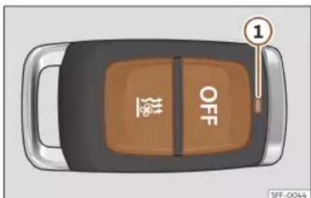
Fig. 132 Auxiliary heating: radio-operated remote control.
Fig. 132
Switch the auxiliary heater on
OFF Switch the auxiliary heater off
① Control lamp
If the buttons of the remote control are pressed unnecessarily, it could switch on the auxiliary heater involuntarily, even when it is
out of range or when the control lamp is flashing.
To switch on and off the independent heating, the button must be pressed and held for approximately 1 second.
Control lamp on the remote control
When the buttons are pressed, the control lamp on the remote control ① provides the user with different information:
It lights up for approx. 2 seconds
• In green: The auxiliary heater has been switched on using the button.
- In red: The auxiliary heater has been switched off con with buttonOFF.
Flashes slowly for approx. 2 seconds
• In green: No on signal has been received. The remote control is out of range. Move closer to the vehicle.
• In red: No off signal has been received. The remote control is out of range. Move closer to the vehicle.
Flashes quickly approx. 2 seconds
• In green: The independent heating is blocked. Possible causes: the fuel tank is almost empty, the 12-volt battery charge is very low or there is a fault.
It lights up for approx. 2 seconds
• In orange (then in green or in red): The remote control battery is almost flat. However, the on or off signal has been received.
• In orange (then flashes green or red): The remote control battery is almost flat. No on or off signal has been received.
Flashes for around 5 seconds
• In orange: The remote control battery is flat. No on or off signal has been received.
Changing the battery of the radio-operated remote control
When pressing the buttons, if the control lamp of the remote ① flashes for approx. 5 orange or does not light up, the batteries must be replaced.
The battery is located beneath a cover on the back of the remote control.
- To open the cover, lift it slightly at the bottom and slide it down.
- Remove the old battery.
- Insert the new battery. When doing so, take into account the polarity and use batteries of the same type>>> 1.
- Replace the battery cover by inserting the tabs at the top and pressing the bottom.
Operation
Range
The receiver is inside the vehicle. The remote control, when fitted with new batteries, has a range of several hundred metres. Obstacles between the remote control and the vehicle, bad weather conditions and discharged batteries can considerably reduce the range of the remote control.
WARNING
Swallowing a battery with a 20 mm diameter or any other button battery can cause serious and even fatal injuries within a very short time.
• Always keep the remote control, keyrings with batteries, the spare batteries, button batteries and all other batteries over 20 mm out of reach of children.
- If you suspect that someone may have swallowed a battery, seek immediate medical attention.
CAUTION
- The radio frequency remote control contains electronic components. Therefore, avoid getting it wet and exposing it to knocks or direct sunlight.
- The use of inappropriate batteries may damage the radio frequency remote control. For this reason, always replace the used battery with another of the same voltage, size and specifications.
For the sake of the environment
- Please dispose of your used batteries correctly and with respect for the environment.
- The remote control battery may contain perchlorate. Observe the legal provisions regarding disposal.
- Care should be taken so as not to operate the remote control unintentionally so as to prevent the auxiliary heater being switched on accidentally.
Programming the auxiliary heater
The activation of the parking ventilation for a scheduled time is only valid for a single ventilation process. The departure time must be for each newly programmed ventilation process.
Before programming the departure time, you must check that the date and time of the car are correctly set.
When programming a departure time, the car automatically calculates, depending on the environmental conditions, the necessary operating time of the parking ventilation.
WARNING
Never programme the auxiliary heater so that it switches itself on and is running in an enclosed space or an area with no ventila-
tion. The auxiliary heater exhaust fumes contain carbon monoxide, an odourless and colourless toxic gas. Carbon monoxide can cause people to lose consciousness. It can also cause death.
Usage instructions
The auxiliary heater exhaust system located below the vehicle must be kept clear of snow, mud and other objects. The exhaust fumes must be able to exit freely. The emissions generated by the auxiliary heater are removed via an exhaust pipe fitted underneath the vehicle.
On heating the vehicle interior, depending on the outside temperature, the warm air is first directed at the windscreen and then to the rest of the vehicle interior through the air vents. Directing the diffusers – towards the windows for example – can affect air distribution.
When the auxiliary heater is not switched on
- The auxiliary heater requires about as much power as the dipped beam headlights. If the 12-volt battery charge is too low, the auxiliary heater switches off automatically and cannot be switched on. This avoids problems when starting the engine.
Air conditioning
• The heating must be activated every time you want to set off. Similarly, the departure time must reactivate each time.
• The control lamp 📋 (fuel level indicator) lights up.
Note
- Noises will be heard while the auxiliary heater is running.
- When the air humidity is high and the inside temperature low, condensation from the heating and ventilating system may evaporate when the auxiliary heater is switched on. In this case, steam may be released from underneath the vehicle. This does not mean that there is a vehicle malfunction.
- If the vehicle is tilted, e.g. if parked on a slope, the operation of the auxiliary heater may be restricted if the fuel tank level is low (just above the reserve level).
- If the auxiliary heater is used a number of times for a long period of time, the 12-volt battery will lose its charge. To recharge the battery, the vehicle must be driven for a number of kilometres from time to time. As a guideline: the journey should last approximately as long as the heater was connected.
- At temperatures below +5 °C (+41 °F), the auxiliary heater may switch itself on automatically when the engine is switched on. The auxiliary heater is switched off again after a certain time.
Stationary air conditioning
Introduction
√ Valid for: hybrid vehicles.
With stationary air conditioning, the vehicle interior can be cooled, ventilated or heated while the vehicle is parked. It can also be used to demist and remove ice or a thin layer of snow from the windscreen. The stationary air conditioning is powered by the vehicle's electrical socket or high-voltage battery.
Stationary air conditioning can be programmed and controlled in the Infotainment system in the Battery Manager menu, through the CUPRA CONNECT mobile App and on the MyCUPRA website.
CAUTION
Food, medicines and other objects sensitive to heat and cold may be damaged or spoiled by the air coming out of the vent.
- Never place food, medicines or other temperature-sensitive objects close to the air vents.
Note
Operating the stationary air conditioning while the charging cable is not connected reduces the vehicle's range. In the case of extreme outside temperatures, the stationary air conditioning may not have sufficient
heating or cooling capacity to reach the desired set temperature.
Operating the stationary air con- ditioning
√ Valid for: hybrid vehicles.
Operation of the stationary air conditioning when the charging connector is not plugged in
The stationary air conditioning can operate when the charging connector is not plugged in. When the charging connector is not plugged in, the stationary air conditioning operates with the high-voltage battery.
- Open the Battery Manager menu.
- Select the settings menu.
- Turn on the Enable High-Voltage Battery Power function if necessary.
The stationary air conditioning only works if the high voltage battery is sufficiently charged.
Setting the desired temperature
- The desired temperature for the stationary air conditioning is selected in the Battery Manager Infotainment system menu using or .
Operation
Switching on the stationary air conditioning
It can be switched on in the following ways:
- Press the immediate on/off button in the mobile App or on the MyCUPRA website.
- Press the immediate on icon in the Infotainment system (while the vehicle is switched off). During immediate air conditioning, the vehicle reaches the set temperature in a maximum of 30 minutes.
- Automatically programming a departure time in the mobile App, on the MyCUPRA website, or in the Battery Manager menu of the Infotainment system» page 160.
Switching off the stationary air conditioning
In can be switched off in the following ways:
- Press the immediate on/off button in the mobile App or on the MyCUPRA website.
- Press the immediate on/off icon in the infotainment system (while the vehicle is switched off). It is only possible to switch it off if the stationary air conditioning was switched on using this button.
- Press the air conditioning off button in the air conditioning menu of the infotainment system (while the vehicle is off).
- Automatically, a few minutes after the scheduled departure time.
• Automatically if the charge level of the vehicle's high-voltage battery drops excessively.
Note
- Operating noises are heard while the stationary air conditioning is connected.
- When the outside humidity is high and the inside temperature low, condensation from the air conditioning system may evaporate when the stationary air conditioning is running. In this case, steam may be released from underneath the vehicle. This does not mean that there is a vehicle malfunction.
Setting the stationary air conditioning
√ Valid for: hybrid vehicles.
The stationary air conditioning can be set in the Infotainment system for the scheduled departure time. You can set the desired temperature of the inside of the vehicle for the vehicle's planned departure time.
Based on the desired temperature, the vehicle calculates the time that the stationary air conditioning needs to be switched on to reach the desired temperature at the departure time.
Vehicle air conditioning prior to departure
- Open the Battery Manager menu.
- Set the scheduled departure time.
- Turn on the air conditioning and charging functions as needed.
If the two air conditioning and charging functions are on at the same time, the high-voltage battery is charged first and then the vehicle is air conditioned. The departure time can only be enabled when one of the two functions has been enabled.
If the charging connector is plugged in, the vehicle starts cooling down around 30 minutes before the scheduled departure time. If the vehicle is not ready to drive at the scheduled departure time, it will be cooled for a further 15 minutes.
If the charging connector is not plugged in, the air conditioning operating time is reduced to 10 minutes. The operating time is extended by 5 minutes if the vehicle is not ready to drive.
The stationary air conditioning switches off automatically.
Extended stationary air conditioning
In the Battery Manager menu can be found an option to add extended air conditioning. This means if the vehicle is air conditioned (either by being switched on immediately or due to departure scheduling), the
Air conditioning
convenience consumers, e.g. seat or rear window heating may switch on automatically if considered necessary by the Climatronic (in cold conditions) before the departure time.
Comfort consumers depend on features.
- Open the Battery Manager menu.
- Tap on the icons of the seats whose convenience consumers should be switched on in addition to the stationary air conditioning. The driver's seat icon always stays activated by default (the driver's seat icon includes the comfort consumers of seat heating and steering wheel heating).
- To turn on the rear window heating before the departure time, switch on the Automatic rear window heating function.
The maximum waiting time for comfort consumers is approximately 10 minutes before the departure time.
Immediate activation of the rear window heating
The rear window heating can be switched on/off using the CUPRA CONNECT mobile app or the MyCUPRA website, regardless of whether or not the stationary air conditioning is switched on.
Vehicle air conditioning when the vehicle is unlocked (with the opening of a door)
- Open the Battery Manager menu.
- Select settings.
- Enable the When unlocking the vehicle function.
The vehicle's air conditioning will switch on as soon as it is unlocked.
Checking the schedule
When the ignition is switched off, the next activated time and the configured functions are displayed in the Infotainment system.
Infotainment system
Infotainment system
Introduction
First steps
Introduction
Infotainment functions and settings depend on the country and equipment
Before first use
Before the first use, bear in mind the following points, to take full advantage of the functions and settings offered:
- Observe the basic safety warnings >> page 162.
- Reset the Infotainment factory settings.
- Search and store favourite radio stations on the preset buttons so you can tune them quickly.
- Use only suitable audio sources and data media.
- Pair a mobile phone to use phone management through the Infotainment system.
- Use current maps for navigation.
- Register in CUPRA CONNECT to run the corresponding services.
Current documentation attached
For using infotainment and its components, take into account, together with this instruction manual, the following documentation:
- Supplements to your vehicle's on-board documentation.
- Instruction Manual of the mobile phone device or audio sources.
- Operating instructions for data media and external players.
- Manuals for the Infotainment accessories subsequently installed or used additionally.
- Description of services when running CU-PRA CONNECT services.
Safety instructions
Some function areas may include links to third-party websites. CUPRA is not the owner of the third-party websites accessible through the links, and assumes no liability for their content.
Some function areas may include outside information from third-party providers. CUPRA is not responsible for such information being correct, up-to-date or complete, or for ensuring it does not infringe the rights of third parties.
Radio stations and owners of data media and audio sources are responsible for the information they transmit.
Bear in mind that parking lots, tunnels, tall buildings, mountains or due to the operation of other electrical devices, such as chargers, can also interfere with the reception of the radio signal.
Foils or adhesives with metallic layers on the antenna and on the window panes can interfere with radio reception.
WARNING
The infotainment central computer is interconnected with the control units mounted on the vehicle. Therefore, there is a serious danger of accident and injury if the central computer is repaired or disassembled and reassembled incorrectly.
- Never replace the central computer with another used, recycled or from another vehicle at the end of its useful life.
• The repair or disassembly and reassembly of the central computer should only be carried out at specialised workshops. To do so, CUPRA recommends going to a specialised CUPRA dealer or any SEAT dealership.
WARNING
The factory assembled radio with integrated software is interconnected with the control units mounted on the vehicle.
Introduction
Therefore, there is a serious danger of accident and injury if the radio is repaired or disassembled and reassembled incorrectly.
- Never replace the radio with another radio that is used, recycled or from another vehicle at the end of its useful life.
- The repair or disassembly and reassembly of the radio should only be carried out at specialised workshops. To do so, CUPRA recommends going to a specialised CUPRA dealer or any SEAT dealership.
WARNING
Any distraction affecting the driver in any way can lead to an accident and cause injuries. Reading the information on the screen and managing the infotainment system can distract your attention from traffic and cause an accident.
• Always drive as carefully and responsibly as possible.
WARNING
Connecting, inserting or removing an audio source or data media while driving can distract your attention from the traffic and cause an accident.
WARNING
Select volume settings that allow you to easily hear signals from outside the vehicle
at all times (e.g. emergency services si-rens).
- Hearing may be impaired if using too high a volume setting, even if only for short periods of time.
WARNING
The following circumstances may result in an emergency call, phone call or data transmission not being made or being interrupted:
- When in areas with zero or insufficient mobile telephony or GPS signal. Also in tunnels, confined areas between very tall buildings, garages, underpasses, mountains and valleys.
- When in areas with sufficient mobile phone or GPS signal, the telephony network of the telecommunications provider has interference or is not available.
- When the vehicle components necessary to make emergency calls, phone calls and to transmit data are damaged, do not work or do not have sufficient electrical power.
- When the battery of the mobile phone device is discharged or its charge level is insufficient.
WARNING
In some countries and some telephone networks it is only possible to make an emergency call, if a mobile telephone de-
vice is connected to the telephone interface of the vehicle, inside it there is an "unlocked" SIM card with sufficient balance to make calls and with sufficient network signal coverage.
WARNING
Read and observe the operating instructions provided by the manufacturer in question when using mobile phone devices, data media, external devices, external audio and multimedia sources.
WARNING
Position the connection cables of the audio sources and external devices so that they do not interfere with the driver.
WARNING
When changing or connecting an audio or multimedia source may cause sudden changes in the volume.
- Lower the volume before connecting or switching to audio or multimedia sources.
WARNING
If mobile phone and radiocommunication devices are used without connection to an external antenna, the maximum electromagnetic radiation levels inside the vehicle might be surpassed, thus posing a risk to the health of the driver and passengers.
Infotainment system
This is also the case if the external antenna has not been correctly installed.
- Keep a distance of at least 20 centimetres between the antennas of the mobile phone device and an active medical device, such as a pacemaker, as mobile phones might alter the functioning of these devices.
- Do not carry a mobile phone switched on very close or directly on top of an active medical device, for instance in a chest pocket.
- Immediately turn off the mobile phone if you suspect it is causing interferences in an active medical device or any other medical device.
WARNING
Mobile phones, external devices and accessories that are loose or not properly secured could move around the passenger compartment during a sudden driving or braking manoeuvre or an accident and cause damage or injury.
- Set mobile phone devices, external devices and their accessories outside the air-bag deployment areas or store them securely.
WARNING
The centre armrest may obstruct the driver's arm movements, which could cause an accident and severe injuries.
- Keep the storage compartments of the centre armrest closed at all times while the vehicle is in motion.
WARNING
If the light conditions are not good and the screen is damaged or dirty, the indications and information displayed on the screen may not be read or be read incorrectly.
- The indications and information displayed on the screen should never induce to take any risk that compromises safety. The screen is not a replacement for driver awareness.
WARNING
Radio stations can transmit disaster or hazard announcements. The following conditions prevent such notices from being received or issued:
- When in areas with zero or insufficient radio signal. Also in tunnels, confined areas between very tall buildings, garages, underpasses, mountains and valleys.
-
When the frequency bands of the radio station have interference or are not available in areas with sufficient radio signal reception.
-
When the speakers and the vehicle components necessary for radio reception are damaged, do not work or do not have sufficient electrical power.
- When the infotainment is switched off.
WARNING
Switch off mobile phone devices in areas with a risk of explosion!
WARNING
The driving recommendations and traffic indications shown on the navigation system may differ from the current traffic situation.
- Traffic signs, signalling systems, traffic regulations and local circumstances prevail over driving recommendations and navigation system indications.
- Adapt your speed and driving style to suit visibility, weather, road and traffic conditions.
- Certain circumstances can significantly initially planned lengthen both the duration of the trip and the route to the destination, or even temporarily prevent navigation to it, for example, if a road is closed to traffic.
Note
In areas where special regulations apply or the use of mobile phones is forbidden, the
Introduction
mobile device in question must be switched off at all times. The radiation produced by a mobile phone device when switched on may interfere with sensitive technical and medical equipment, possibly resulting in malfunction or damage to the equipment.
Note
If the playback volume is excessive or distorted, the speakers may be damaged.
Infotainment system
Overview and controls
Connect System

Fig. 133 Overview: control unit
① Touch screen. The infotainment functions can be used through the screen.
② HOME button.
③: main menu with widget views.
⊕: main menu in mosaic mode.
③ Direct access button to the assist systems and vehicle settings.
④ Touch zone (to turn the infotainment system on or off).
⑤ Touch zones (to raise and lower the air conditioning temperature).
⑥ Touch zones (to raise and lower the volume).
Introduction
General instructions for use
Operating indications
- The infotainment needs a few seconds for the complete start-up of the system and during that time it does not react to inputs. Only the image of the rear view camera system can be displayed during system start-up.
- The display of all indications and the execution of functions only takes place once the infotainment system has finished booting. The duration of the system booting depends on the number of infotainment functions and may take longer than normal in the event of very high or very low temperatures.
- When using the infotainment system and corresponding accessories, e.g., headphones, bear in mind country-specific regulations and legal provisions.
- Some functions of the infotainment system require an active CUPRA CONNECT user account and an Internet connection for the vehicle. The data transmission must not be limited to perform the functions.
- To use the infotainment system, simply lightly press a button or touch the screen.
-
For the correct operation of the infotainment system it is important that it is switched on and that, if necessary, the time and date of the vehicle are set correctly.
-
If a function button is missing on the screen, it is not a device defect, but corresponds to the specific equipment of the country or version.
- Some infotainment functions can only be selected when the vehicle is at a standstill. In some countries the parking lock must also be enabled (button P) or the selector control must be in the neutral position N. This is not a malfunction, but is due to compliance with legislation.
- Restrictions on the use of devices using Bluetooth® technology may apply in some countries. For further information, contact the local authorities.
- If you disconnect the 12-volt battery, turn on the ignition before restarting the infotainment system.
- If the setup is changed, this may change the display on the screen and in some cases, the infotainment system may behave in a manner different to that described in this instruction manual.
- Ensure that any repairs or modifications that need to be carried out on the infotainment system are carried out by a specialised workshop. To do so, CUPRA recommends going to a specialised CUPRA dealer or any SEAT dealership.
-
Using a mobile phone device inside the vehicle may cause noise in the speakers.
-
In some countries, the infotainment system automatically shuts off when the engine is switched off and the vehicle's 12-volt battery charge level is low.
- On vehicles with park assist, the audio source volume is automatically lowered when reverse gear is selected. The volume reduction can be adjusted.
• Information about the included software and the license conditions can be found in Settings > Copyright. - When selling or lending the vehicle, make sure that all saved data, files and settings have been deleted and, if necessary, external audio sources and data media have been removed.
Note
You will find more information and tips for using the infotainment system in the Help menu.
HOME screen
In the control and display unit you can set up the views and representation on the home screen or use the factory setting templates.
If an icon is missing on the screen, it is not a device defect, but corresponds to the specific equipment of the country or version.
Infotainment system
The following menus can be included as an icon on the home screen:
Main menus on the home screen

Navigation»» page 193

Radio >> page 186, Multimedia
page 190

Telephone»» page 200

Full Link >> page 178

Setup>>>page 169

Vehicle»» page 89

Data>>>page 88

Air conditioning >> page 147

Sound

Users

Store

Legal

Help
Managing the infotainment sys- tem
Execute the functions and settings with the infotainment controls.
Depending on the equipment, the infotainment system has different controls:
- Touch screen.
- Touch zones outside the screen, for example, Volume (+ -).
Help Menu
This menu displays information on the operation of the infotainment system and gives practical tips.
- Press ? Help.
Connecting and disconnecting the info-tainment system
The infotainment system turns on when the ignition is switched on, unless it has been manually turned off beforehand.
The infotainment system starts-up with the last set volume, provided that this does not exceed the preset maximum start-up volume.
The infotainment system automatically turns off when the driver's door is opened, provided the ignition has been switched off beforehand.
Moving objects and adjusting volume
Move objects on the screen to adapt settings, for example, with scrollable buttons or to move the areas of a menu.
Depending on the equipment, customise menus and views.
Increasing and reducing images or map sizes
Tip: use your thumb and index finger.
- Press on the map with both fingers at the same time and leave them on the screen.
- To enlarge views, slowly separate one finger from the other. To reduce views, slowly bring one finger towards the other.
Note
If you turn on the infotainment system manually with the ignition off, it will automatically turn off after about 30 minutes.
Customising the infotainment system
Customise the menus and infotainment views to quickly access your favourite or most frequently used functions.
The main menu contains function buttons for accessing all of the Infotainment apps.
Introduction
Configuring customised menus
In all views (except Main Menu, StandBy, Parking, Speller and Full Link), you will find shortcuts to customizable system functions in the lower part of the screen. Use the settings to delete or replace them, or change their order.
- Press and hold one of the icons (or press on the icon of an empty position) to display an additional window.
- Select one of the icons from the apps bar.
- PressX to delete an icon.
- Click on an icon in the additional window to replace the value.
- Hold your finger on one of the icons and drag it to the desired position.
- To close the edit mode, pressX in the additional window.
Adapting customised menus
- Press a function button in a customised menu and keep your finger on the screen until an additional window is displayed.
- Press the function button to which you want to add a function.
- Click close to return to the custom menu.

Note
- At least two customised menus are always available. These cannot be deleted.
- You can add a maximum of two more customised menus (in total, a maximum of four customised menus).
- For some function buttons, more functions are available than those seen at first sight in the additional window. To find all the functions, in the additional window slide the screen to the left or right.
- For the drop-down menu, more functions are available than those seen at first sight in the additional window. To find all the functions, in the additional window slide the screen to the left or right.
- The shortcut bar cannot be edited when the vehicle is moving.
Settings (system and sound)
The selection of possible settings varies depending on the country, the equipment in question and the equipment of the vehicle.
Modifying settings
The meaning of the following symbols are valid for all system and sound settings.
All changes are automatically applied when the menus are closed.
Symbol and its meaning

The setting is selected and activated or connected.
Symbol and its meaning

The setting is not selected, disabled or disconnected.

To open a drop-down list.

To increase a setting value.

To increase a setting value.

To go back step by step.

To go forward step by step.

To change a setting value with the scroll-lable button without adjusting.
Sound settings
Accessing the sound settings: press 🔊 Sound
In the sound settings there may be the following functions, information and setting options:
• Equaliser.
- Position.
- Settings.
System settings
Accessing the system settings: press ⚙ Settings.
》
Infotainment system
In the system settings there may be the following functions, information and setting options:
- Screen.
• Time and date. - Language.
• Additional keypad languages. - Units.
- Voice control.
• Wi-Fi.
• Data connection. - Manage mobile devices.
- Reset factory settings.
• System information.
• Copyright. - Configuration wizard.
Adjust the volume of external audio sources
If you need to increase the playback volume for the external audio source, first lower the volume on the infotainment system.
If the sound from the connected audio source is very low, increase the output volume on the external audio source. If this is not enough, change the input volume to medium or high.
If the sound from the connected external audio source is too loud or distorted, lower the output volume on the external audio source. If this is not enough, change the input volume to medium or low.
Clean the screen
Remove persistent dirt carefully and without using aggressive cleaning products. To clean the screen we recommend that:
• The infotainment system is switched off.
- Use a clean, soft cloth dampened with water»» page 353.
- In case of persistent dirt: soften the dirt by moistening with a little water. Then carefully remove with a clean, soft cloth.
CAUTION
Cleaning the screen with inappropriate cleaning products or when dry, may damage it.
- When cleaning, only press lightly.
- Do not use aggressive cleaning products or that contain solvents. Such products may damage the equipment and “darken” the screen.
Trademarks, licenses and copy- rights
Registered trademarks and licenses
Certain terms in this manual bear the symbol or TM . These symbols indicate that it is a trademark or a registered trademark. The absence of this symbol, however, does not necessarily mean that the term in question can be used freely.
Other product names are registered trademarks or trademarks of the respective rights holders.
• Manufactured under license from Dolby Laboratories. Dolby and the double-D symbol are trademarks of Dolby Laboratories.
• Manufactured under license from Dolby Laboratories. Dolby and the double-D symbol are trademarks of Dolby Laboratories.
- Android Auto™ is a trademark of Google Inc.
- Apple CarPlay™ is a trademark of Apple Inc.
- Bluetooth® is a registered trademark of Bluetooth® SIG, Inc. iPod®, iPad® and iPhone® are trademarks of Apple Inc.
- MirrorLink™ and MirrorLink Logo are certified trademarks of Car Connectivity Consortium LLC.
Introduction
- Windows® is a registered trademark of Microsoft Corporation, Redmond, USA.
- MPEG-4 HE-AAC audio coding technology and patents are licensed by Fraunhofer IIS.
- This product is protected by certain Microsoft Corporation industrial and intellectual property rights. The use or commercialization of technology of this type outside the configuration of this product, without a licence from Microsoft or an authorised Microsoft branch is prohibited.
Copyright
As a general rule, audio and video files stored on data media and audio sources are subject to intellectual property protection in accordance with the national and international provisions applicable in each case. Please bear in mind all legal provisions!
Technical data
Central computer with control and display unit
The factory-mounted central computer in the vehicle includes country-specific components and software for connectivity and for the execution of vehicle, comfort and infotainment functions.
The corresponding indications are shown on the control and display unit screen and partly on the instrument panel.
■ Capacitive colour screen:
■ Using the equipment with:
■ Touch zones Touch operation.
- Buttons on the multifunction steering wheel.
■ Proximity sensors and gesture control.
Vehicle and comfort functions
■ Driver assistance system settings.
■ Heating and air conditioning settings.
■ Lights and visibility function settings.
■ Vehicle comfort settings.
■ Parking and manoeuvring settings.
Sound system
Basic equipment:
The infotainment system that is supplied from the factory is equipped as follows:
■ Speakers in different locations and with different power levels (watts).
■ Internal amplifier depending on the system:
■ 7 speakers: 5 x 20 W
■ Setting options:
■ Equaliser, depending on the system:
■ 7 speakers: 5 frequency bands or predefined settings.
■ Sound distribution, depending on the system:
■ 7 speakers: Balance + Fader (left / right / front / rear).
■ Sound optimisation by zones (valid for the 7 speaker system):
■ Manual (Driver and All)
■ Automatic depending on the seats occupied.
Optional sound system
The infotainment system can be extended with an optional sound system as follows:
■ 10 speakers in different locations and with different power levels (watts).
■ External amplifier (340 W Ethernet), which processes the audio signals sent by the central computer.
■ Excitation of speaker channels through class AB final stages.
■ Audio signal processing in digital internal signal processor (DSP).
■ Independent subwoofer in the luggage compartment.
■ Setting options:
■ User equaliser: 5 bands.
■ Equaliser settings predefined by BEATS® (Signature, Active, Immersive and Voice). »
Infotainment system
■ Sound distribution: Balance + Fader (left / right / front / rear).
■ Sound optimisation by zones:
■ Manual (Driver, Front and All)
■ Automatic depending on the seats occupied.
■ Subwoofer volume.
■ Surround settings.
Connectivity
Wi-Fi
■ Wi-Fi conforming to IEEE 802.11 b/g/n
■ 2.4 GHz and 5 GHz transfer (depending on the country)
■ Two Wi-Fi modes at the same time:
■ Tethering.
■ Access point.
■ Simultaneous connection of up to 8 Wi-Fi devices.
■ Internet connection via Wi-Fi:
■ Tethering through the customer's phone.
■ Access point for customers in the vehicle.
■ Apple CarPlay and Android Auto over Wi-Fi.
■ Pairing process simplified by WPS or QR code.
Bluetooth® profiles
There can be a maximum of two mobile devices connected to the Bluetooth® hands-free and a third device connected to the Bluetooth® as a music player.
When a mobile phone is connected to the telephone management system, a data exchange takes place via one of the Bluetooth® profiles.
- Hands-free telephone profile (HFP): the HFP can be used to manage calls through the infotainment system.
• Audio profile (A2DP): This profile allows audio to be transmitted with stereo quality. It may require connecting other profiles for managing and controlling playback.
- Phone book access profile (PBAP): Allows phone book contents to be downloaded from the mobile telephone.
- Message profile (MAP): It allows short messages (SMS) and emails to be downloaded and synchronised.
Data transfer
Data transfer
CUPRA CONNECT
Introduction
To use it, CUPRA CONNECT must first be activated online by entering into a CUPRA CONNECT contract with SEAT, S.A. and is subject to a temporary use limitation depending on the country.
Both the CUPRA CONNECT service portfolios offered by CUPRA and individual services can be modified, cancelled, deactivated, re-activated, renamed and extended, even without prior notification.
You can create the user account, see the description of services and more information at myCUPRA.com.
The execution and availability of the CUPRA CONNECT services and service portfolios may vary depending on the country, as well as the vehicle, its equipment and connectivity.
Connectivity statuses
| (white) | Full connectivity, all services active |
| (grey) | Limited connectivity, some services may not be available. |
| no icon No connectivity, no services available. | |
CUPRA CONNECT's voice recognition or search technology does not recognise or offer results for all words.
There are CUPRA CONNECT services for which registration is mandatory and others for which it is not mandatory.
Description of services
Before running CUPRA CONNECT services, read and take into account the description of the corresponding services. Descriptions are updated from time to time and are available online at myCUPRA.com.
• Always use the most up-to-date version of the corresponding service description.
WARNING
In areas with insufficient mobile phone and GPS coverage, neither emergency calls or phone calls can be made, and data cannot be transmitted. Change location if possible.
CAUTION
The vehicle may be damaged by factors outside CUPRA's control. These may be specifically:
- Misuse of mobile terminals
• Data loss during transmission. - Unsuitable or defective third party applications.
- Malicious software on data storage devices, computers, tablets or mobile phones.
Services portfolio
The initial service allocation shown here corresponds to the third generation of CUPRA CONNECT services and represents the maximum services portfolio. The maximum possible portfolio is only available on some vehicle models. During the useful life of the vehicle, you can change the assignment shown here.
After activating the services management in the infotainment system you can check if the vehicle has services and what they are.
In some countries and in the event of a contract renewal, the services offered may be combined differently than indicated here. They may also vary depending on the year of production of the vehicle. The aforementioned services correspond to the third generation of CUPRA CONNECT.
CUPRA CONNECT services and functions that do not require activation
The following services also work without activating CUPRA CONNECT:
• Public emergency call service.
- Privacy mode»» page 177.
Infotainment system
- Legal.
- Customisation.
- Activating CUPRA CONNECT.
- Private mode (deactivation of services).
- Delete user / Restore factory settings.
CUPRA CONNECT services
The CUPRA CONNECT services are:
- Private emergency call
• Public emergency call
• Roadside assistance call - Customer support
• Service appointment planning
• Online system update - Customisation
• Activating CUPRA CONNECT - Private mode (deactivation of services)
- Delete user / Reset factory settings
• Remote independent heating - Remote opening
- Horn and turn signals
• Vehicle status incl. doors and lights - Driving data
- Vehicle status report
• Anti-theft alarm warning - Zone warning
- Speed warning
• Online map update
• Search for points of interest
- Petrol stations
• Online traffic information
- Parking lots
• Online infotainment system update
• Online route calculation
• Information on risks
- Dictation
- Natural voice control for infotainment, media and radio apps
• Natural voice control for destinations and addresses
- Online radio
- Online media
• Online route import
• Online destination import
- Remote auxiliary ventilation
- Parking position
- Privacy mode
• Legal
CUPRA CONNECT services for hybrid vehicles
Available only in electric and hybrid vehicles.
-
Remote air conditioning
• Electrical power manager -
Departure times
- plus all CUPRA CONNECT services in the previous section»» page 174.
CUPRA CONNECT individual options
- In-Car Applications. These applications can be purchased and installed directly in the infotainment system through the In-Car store.
• Full Link. - Data package. Pay per use data rates for the use of online functions, for example, 2 GB per month.
Note
- The public emergency call service is available regardless of whether the info-tainment system is logged in.
- Customisation and purchase of In-Car applications requires logging into the infotainment system, but it is not necessary to activate the vehicle in a CUPRA CONNECT account.
Activating CUPRA CONNECT and S-PIN
Activating CUPRA CONNECT
The following steps are necessary to activate CUPRA CONNECT (including registration):
Data transfer
- Create a user account at myCUPRA.com or directly through the infotainment system in the User Management menu.
- Place the CUPRA CONNECT order and activate it.
- Add the vehicle to your user account.
• Prove ownership. - Prove your identity. It is only necessary if you are to run CUPRA CONNECT services relevant to security.
- You can activate it at myCUPRA or directly through the infotainment system. To activate it through the infotainment system, proceed as follows: ⚙Users > Settings > Become primary user.
Follow the rest of the indications and the information shown in the infotainment system. During activation, you may be asked to create an S-PIN.
Update option
| Infotainment yes | |
| CUPRA CONNECT website yes | |
| CUPRA CONNECT application yes |
More information at myCUPRA.com/faqs
S-PIN
The S-PIN is a sequence of several digits, which can be selected when the CUPRA CONNECT registration is completed.
When creating the S-PIN, avoid easy-to-guess number sequences and known dates of birth. You can change the S-PIN in the CUPRA CONNECT user account in "Account settings".
The S-PIN is necessary, for example, to protect your user profile or to run a CUPRA CONNECT service relevant to the security of your vehicle.
You must manage this S-PIN with absolute confidentiality. If you reveal the S-PIN to third parties, for security reasons you must change it immediately.
Ownership and identity accreditation
Become primary user
To become a main user and thus prove ownership of the vehicle, you need both of the vehicle's physical keys. Ownership accreditation takes place in the vehicle during registration or, if you already have a CUPRA CONNECT user account, you must log in through the infotainment system and then go to
Manage users
- Switch on the ignition and the infotainment system.
- In the infotainment system, register in CU-PRA CONNECT.
- Or: open the menu ⚙ Users > Settings > Become primary user and follow the instructions.
- Press the unlock button on the first vehicle key.
- Press the unlock button on the second vehicle key.
Once the infotainment system has processed the orders by radiofrequency, the accreditation of the ownership will have been completed. You can control the current status on the CUPRA CONNECT website.
How is ownership accredited?
| Infotainment 2-Key method. | |
| CUPRA CONNECT web-site | No, it is not possible |
| CUPRA CONNECT application | No, it is not possible |
Identity accreditation (SEAT Ident)
Identity accreditation must be completed before you can use CUPRA CONNECT services that are relevant to security, such as the »
Infotainment system
"Remote Opening" service. Identity accreditation is done at the specialised CUPRA dealer or any SEAT dealership.
You can find more information about SEAT Ident on the CUPRA CONNECT website at myCUPRA.com.
Legal provisions
When using CUPRA CONNECT services, information is transferred and processed online through the vehicle. Such data can also provide (at least indirectly) information about the driver in question, for example, driving behaviour and location. As a contracting party in the CUPRA CONNECT contract with SEAT, S.A., you must ensure that when your vehicle is used by other drivers (for example, family or friends), data protection and personal rights are respected. Therefore, you must inform drivers in advance that the vehicle transfers and receives data online, and that you can access such data.
Not taking into account this obligation to inform, can infringe certain rights of the occupants.
Users can manage data sending and transfers through the privacy mode at any time. For more information visit: myCUPRA.com/faqs
Follow-up services: ask all occupants
The follow-up services need geographical and vehicle data to determine whether the vehicle is being used within defined speed ranges, where it has been parked or if it is being used in an established geographical area. This information is displayed on the CUPRA CONNECT website and in the CUPRA CONNECT app.
Therefore, before moving off, ask all the vehicle occupants if they agree with the activated services. If they do not, deactivate the service in question (if possible) or do not allow the occupants to use the vehicle.
GPS tracking: marking
If the vehicle has a factory-assembled control unit that transmits the its current geographical position and speed, the vehicle usually has this GPS marking (e.g., on the roof console). The absence of the marking on the vehicle does not guarantee that the control unit does not transmit the vehicle's current geographical position and speed.
Personal information
CUPRA protects your personal data and only uses them, as long as the law allows it or you have given your consent on the occasion of a use. You will find detailed information on data processing in relation to CUPRA CONNECT services in the Privacy Policy, which
you can access in its corresponding current version on the CUPRA website.
Permanent transfer of the vehicle
If another person has left you the vehicle for permanent use (for example, if you buy a used vehicle), CUPRA CONNECT may already be activated and the previous user may still be able to access the data registered through CUPRA CONNECT and control certain functions of your vehicle.
In the infotainment system you can check if your vehicle is assigned to a person as the main user. In this case, you can register yourself as the main user of the vehicle and thus automatically delete the previous main user. Alternatively, through the infotainment system you can directly and permanently delete the previous user as the main user, as well as put the vehicle in offline mode and thus limit both the communication of your vehicle with the SEAT, S.A. data server and the processing of personal and vehicle data.
Deactivating CUPRA CONNECT services
The following functions are available in the infotainment system to deactivate and activate CUPRA CONNECT services:
• Central deactivation or activation
Data transfer
• Individual deactivation or activation
You can rerun the corresponding services after cancelling their deactivation in the info-tainment system.
Note
The services required by law and their data transmission, such as the public emergency call system, cannot be disconnected or deactivated.
Faults
Even if the prerequisites for the use of CU-PRA CONNECT services are met, there may be factors beyond the control of CUPRA that interfere with the execution of such services or prevent them. These may be specifically:
- Maintenance, repair, deactivation, software update and technical expansion of telecommunication equipment, satellites, servers and data banks.
- Change of the mobile telephony standard for the transmission of mobile data by the telecommunications service provider, for example, from UMTS to EDGE or GPRS.
- Disconnection of an existing mobile phone standard by the telecommunications service provider.
• Interference, disturbance or interruption in the reception of the mobile phone and GPS signal due to aspects such as high-speed driving, solar storms, meteorological influences, topography, blocking equipment and the intensive use of mobile phones in the radio cells in question.
- When in areas with zero or insufficient mobile telephony or GPS signal. Also, for example, in tunnels, confined areas between very tall buildings, garages, underpasses, mountains and valleys.
- External information from third party supplies available with limitations, incomplete or incorrect, e.g. representations of maps.
- Countries and regions where CUPRA CONNECT is not offered.
Service management
Open the settings in Users and go to Privacy settings and services. You can do the following in the infotainment system:
- Check which CUPRA CONNECT services are currently available in the vehicle.
- The number of CUPRA CONNECT services that are activated or deactivated.
- Activate or deactivate CUPRA CONNECT services.
Find out more information at: myCUPRA.com.
Privacy and Services Settings
CUPRA CONNECT services can be activated and deactivated individually. To do this, just check the box corresponding to the service you want to activate or deactivate. Use the privacy mode option if you want to deactivate all of the services at the same time.
Privacy mode
Allows you to deactivate or activate the services depending on the selected privacy level.
| Tracking | Share location. Main users and co-users can view position data on the CU-PRA CONNECT portal or app. |
| Location | Use location. Position, vehicle, and user data are used for services. |
| Personal | No location. Only the vehicle data and user data are used for services. |
| Incognito | Maximum privacy. Your services are disabled. Only services required for legal reasons use data. |
Setting options are not available in all markets or in all vehicle models.
Infotainment system
Note
If you deactivate all CUPRA CONNECT services, the OCU may continue to transmit data.
Full Link
Introduction
With Full Link it is possible to view and use the contents and functions that are shown on the mobile phone device on the infotainment screen.
To do this, the mobile phone device must be connected with the infotainment system through a USB interface.
Some technologies can also be used by Wireless Full Link through the Bluetooth® interface and a Wi-Fi connection.
The following technologies may be available:
- Apple CarPlay™
• Apple CarPlay™ Wireless - Android Auto™
- Android Auto™ Wireless
- MirrorLink®
The availability of the technologies that Full Link includes depends on the country and the mobile phone device used.
You can find more information on the CU-PRA website.
Access the Full Link main menu
Browsing the Full Link main menu depends on the infotainment system used.
- Click on Full Link.
Configure Wireless Full Link
In order to use Wireless Full Link, you must first pair the mobile phone device with the infotainment system. To do this, proceed as follows:
Connect a mobile phone device for the first time.
- Unlock the mobile phone device.
- Enable Wi-Fi reception and Bluetooth® on the mobile phone device.
- Connect the mobile phone device to the infotainment system using a USB cable or via Bluetooth®.
- Access the Full Link main menu, unless it appears automatically.
-
Select the mobile phone device and the technology you want.
-
Confirm authorisation inquiries on the mobile phone device to grant the necessary authorisations to the infotainment system.
- Disconnect the USB connection and connect with the infotainment system again via Wi-Fi or Bluetooth®. Wireless Full Link is now configured.
The pairing has concluded. The connected mobile phone device can also use Wireless Full Link from now on without the USB connection.
If pop-up menus are rejected during the connection process, Wireless Full Link will not be available. In this case, CUPRA recommends removing the devices in both the telephone settings and the infotainment system, and restarting the connection process.
WARNING
The use of applications while driving can distract your attention from the traffic. Any distraction affecting the driver in any way can lead to an accident and cause injuries.
• Always drive as carefully and responsibly as possible.
WARNING
Any applications that are not suitable or execute incorrectly may cause damage to the vehicle, accidents and serious injuries.
Data transfer
- Protect the mobile phone device and its applications from inappropriate use.
- Never carry out modifications to the applications.
- Follow instructions in the instruction manual for the mobile phone device.
CAUTION
CUPRA cannot be held liable for any damage caused to the vehicle as a result of the use of applications that are of poor quality or are defective, the inadequate programming of the applications, the insufficient coverage of the network, the loss of data during transmission or the improper use of mobile phone devices.
Note
- Wireless Full Link may not be compatible with all technologies.
- Wireless Full Link (Android Auto™ and Apple CarPlay™) is disabled in countries whose radio frequency regulations do not allow it to operate.
Applications (apps)
With Full Link, the display of the contents of CUPRA applications and other providers installed on mobile phone devices can be transferred to the infotainment screen.
In the case of third-party applications, there may be compatibility problems.
Applications, their use and the necessary mobile phone connection may be pay per use.
The offer of applications can be varied and designed for a vehicle or a specific country. The content and volume of applications, as well as the companies that offer them, may vary. Some applications also depend on the availability of third-party services.
It cannot be guaranteed that all the applications offered will work on all mobile phone devices or with all their operating systems.
The applications offered by CUPRA can be modified, cancelled, deactivated, reactivated and extended without prior notification.
To avoid distracting the driver while driving, only certified applications can be used.
Full Link symbols and settings
To show more information
To open the Full Link settings menu
To select Apple CarPlay technology.
To select Android Auto™ technology.
To select Mirror Link® technology.
Apple CarPlay™
In order to use Apple CarPlay, the following requirements must be met:
- The iPhone™ must be compatible with Apple CarPlay™.
- Voice control (Siri™) must be active on the iPhone™.
- Apple CarPlay™ must be active without limitations in the iPhone™ settings.
- The iPhone TM must be connected to the infotainment system via a USB connection. Only USB connections with data transmission are suitable for the use of Apple CarPlay TM .
- The USB cable used must be an original Apple™ cable.
Apple CarPlay™ Wireless: Bluetooth® and Wi-Fi must also be activate on the iPhone™.
Establish connection
When you first connect an iPhone™, follow the instructions on the infotainment system screen and on the iPhone™.
The requirements must be met to use Apple CarPlay™.
Launch Apple CarPlay™:
- Press Full Link to access the Full Link main menu.
》
Infotainment system
- Press Apple CarPlay™ to establish a connection with the iPhone™.
Disconnecting
- In Apple CarPlay™ mode, press the CUPRA icon to access the Full Link main menu.
- Press X to interrupt the active connection.
The representation of function buttons on the screen may vary.
Special characteristics
During an active Apple CarPlay™ connection, the following characteristics are applicable:
- Bluetooth® connections between the iPhone™ and the infotainment system are not possible.
- If there is an active Bluetooth® connection, it is automatically interrupted.
- The phone functions are only available through Apple CarPlay™. The functions described for the Infotainment system are not available.
- The connected iPhone™ cannot be used as a multimedia device in the Media main menu.
-
It is not possible to use the built-in navigation system and the Apple CarPlay™ navigation system at the same time. The last route started interrupts the one that was previously active.
-
Depending on the infotainment system you use, on the instrument panel screen you can view data from the Telephone and Media mode.
- With the multifunction steering wheel you can accept or reject incoming calls, as well as end an ongoing telephone conversation.
voice control
- Press ⬆ briefly to start voice control using the infotainment system.
- Press this button for a long time to start voice control (Siri™) of the connected iPhone™.
Note
- The availability of technologies depends on the country and may vary.
- You will find information about technical requirements, compatible iPhones, certified applications and their availability on the CUPRA and Apple CarPlay™ websites, at specialised CUPRA dealers.
Android Auto™
Requirements for Android Auto™
In order to use Android Auto™, the following requirements must be met:
- The mobile phone device, called smartphone from here on, has to be compatible with Android Auto™.
- The smartphone must have an Android Auto™ application installed.
- The smartphone has to be connected through the USB connection with data transmission with the infotainment system.
- The USB cable used must be an original cable provided by the smartphone manufacturer.
Android Auto™ Wireless: Bluetooth® and Wi-Fi also have to be activated on the device.
Establish connection
When you first connect a smartphone, follow the instructions on the infotainment system screen and on the smartphone.
The requirements must be met to use Android Auto™.
Launch Android Auto™:
- Press Full Link to access the Full link main menu
Data transfer
- Press Android Auto™ to establish a connection with the smartphone.
Disconnecting
- In Android Auto™ mode, press the Exit/SEAT icon to access the Full Link main menu.
- Press X to interrupt the active connection.
Special characteristics
During an active Android Auto™ connection, the following characteristics are applicable:
- An active Android Auto™ device can be connected at the same time via Bluetooth® (HFP profile) with the infotainment system.
- It is possible to use the phone's functions through Android Auto™. If the Android Auto™ device is connected at the same time via Bluetooth® with the infotainment system, the telephone function of the infotainment can also be used.
- An active Android Auto™ device cannot be used as a multimedia device in the Media main menu.
-
It is not possible to use the built-in navigation system and the Android Auto™ navigation system at the same time. The last route started interrupts the one that was previously active.
-
On the instrument panel screen you can view data from the Telephone and Media mode.
- With the multifunction steering wheel you can accept or reject incoming calls, as well as end an ongoing telephone conversation.
voice control
- Press Ωφ briefly to start voice control using the infotainment system.
- Press and hold this button to start voice control (Google Assistant) on the connected smartphone.
Note
- The availability of technologies depends on the country and may vary.
- You will find information about technical requirements, compatible mobile phone devices, certified applications and their availability on the CUPRA and Android Auto™ websites, at specialised CUPRA dealers.
MirrorLink®
Requirements for MirrorLink®
In order to use MirrorLink™, the following requirements must be met:
- The mobile device must be compatible with MirrorLink™.
- The mobile phone device must be connected to the infotainment system via a USB connection that is suitable for data transmission.
- The USB cable used must be an original cable provided by the mobile phone device manufacturer.
- Depending on the mobile phone device used, a Car-Mode application that is suitable for using MirrorLink® must be installed.
Establish connection
When you first connect a mobile phone device, follow the instructions on the infotainment system screen and on the mobile phone device.
The requirements must be met to use MirrorLink ™ .
Launch MirrorLink®:
- Press Full Link to access the Full Link main menu.
- Press to establish the connection with the mobile phone device.
Disconnecting
- In the MirrorLink® mode, press theAPP icon to access the Full Link main menu.
- OR: press to access the MirrorLink® main menu.
- Press X to interrupt the active connection. »
Infotainment system
Special characteristics
During an active MirrorLink® connection, the following characteristics are applicable:
- An active MirrorLink® device can be connected to the infotainment system at the same time via Bluetooth®.
- If the MirrorLink® device is connected to the infotainment system via Bluetooth®, the telephone function of the infotainment system can be used.
- You cannot use an active MirrorLink® device as a multimedia device in the Media main menu.
- On the instrument panel screen you can view data from the Telephone mode.
- The instrument panel screen does not display any indication to turn or the Media mode.
- With the multifunction steering wheel you can accept or reject incoming calls, as well as end an ongoing telephone conversation.
Function buttons
Function buttons and their function:
APP Return the Full Link main menu. Here you can end the MirrorLink® connection, connect another mobile phone device or select another technology.
✗ Press to close the open apps. Then press the apps to be closed or the Close
all function button to close all the open applications.
Press to display the mobile phone device screen on the infotainment system screen.
To open the MirrorLink® settings.
Press to return to the MirrorLink® main menu.
Note
You will find information about technical requirements, compatible mobile phone devices, certified applications and their availability on the CUPRA and MirrorLink® websites, at specialised CUPRA dealers.
WLAN access point
Introduction
√ Not available on vehicles without CUPRA CONNECT and without navigation
The infotainment system can be used to share a WLAN connection with up to 8 devices»» page 182, Configuration for sharing a connection over WLAN.
The infotainment system can also use the WLAN hotspot of an external device to provide Internet to the devices connected to the hotspot (WLAN client)» page 183.
Note
- Data transmission may incur charges. Due to the high volume of data exchanged, CUPRA recommends the use of a flat rate tariff for data transmission. Mobile phone operators can provide the relevant information.
- The exchange of data packages may generate additional costs, depending on your mobile phone rate, particularly if you are abroad (for example, roaming rates).
Configuration for sharing a connection over WLAN
Establishing the connection with the wireless network (WLAN)
- Press the ⚙ Settings button.
- Activate the wireless network. To do this, press the function button Wi-Fi > Infotainment system as hotspot.
- Activate the wireless network (WLAN) on the device that is to be connected. If necessary, refer to the manufacturer's instruction manual.
- Activate the mobile device assignment in the infotainment system. To do this, press the function button Enable as hotspot and check the checkbox.
- Enter and confirm the network key displayed on the device.
Data transfer
The following adjustments can also be made in the Infotainment system as hotspot menu:
• Security level: WPA2 encryption automatically generates a network key.
- Network key: Network key automatically generated. Press the function button to manually change the network key. The network key must have a minimum of 8 characters and a maximum of 63.
- SSID: WLAN Network name (maximum of 32 characters).
The wireless (WLAN) connection is established. To complete the connection, it may be necessary to enter other data into the device.
Repeat this process to connect other devices.
There is also the option of scanning the QR code by connecting the device directly to the infotainment system's Wi-Fi network without having to enter the password: select Settings > Wi-Fi > Quick connection to infotainment system.
Wi-Fi Protected Setup (WPS)
√ This depends on the equipment and the country in question.
Wi-Fi Protected Setup can be used to create a ciphered local wireless network quickly and simply.
- Establish the connection with the wireless network (WLAN).
- Press the WPS button on the WLAN router until the warning light on the router starts flashing. If the WLAN router does not support WPS the network must be configured manually.
- OR: Press and hold the WLAN button on the WLAN router until the WLAN light on the router starts flashing.
- Press the WPS button on the WLAN device. The wireless (WLAN) connection is established.
Repeat this process to connect other devices.
Configure Internet access
The infotainment system can use the WLAN hotspot of an external device to establish an Internet connection.
Establishing the connection with the wireless network (WLAN)
- Activate and check the wireless hotspot on the external device. If necessary, refer to the manufacturer's instruction manual.
- Press the Ⓧ Settings button; OR access the Media and press the Settings menu.
- Press the Wi-Fi > Connect to Wi-Fi menu and put a check in the checkbox.
- Press the Search for Wi-Fi button and select the device you want from the list.
- If necessary, enter the network key of the device in the infotainment system and confirm with OK.
Manual settings:
- To manually enter the network settings of an external (WLAN) device.
The wireless (WLAN) connection is established. To complete the connection, it may be necessary to enter other data into the device.
Note
Due to the large number of devices on the market, it is not possible to guarantee fault-free operation of all functions.
Infotainment system
Infotainment operation
voice control
Introduction
Voice control works both online and offline. In online mode, commands are recorded more accurately, as more data is available.
Voice control understands questions and expressions without having to learn commands. Commands can be formulated freely and can be colloquial. You will find proposals for commands in the infotainment system.
Functions are reduced in offline mode.
Loud noises inside or outside the vehicle can cause malfunctions, as well as confusing phrases and answers.
Languages available depending on the market
Online and offline: German, American English, British English, French, Italian, Spanish and Czech. These languages have advanced functions such as Online Commands, air conditioning control, natural interaction, etc.
The other languages of the infotainment system do not offer Online Commands, air conditioning control or natural interaction.
Requirements
- Online and offline: voice control with the corresponding infotainment installed in the vehicle.
• Online current active CUPRA CONNECT Plus contract.
Note
- Voice control only recognises commands in the language that is set in the infotainment system.
- Test the voice control with the vehicle stopped before starting to move to familiarise yourself with its operation.
• Additional information and examples can be found in the menu Home > Help > Voice control
Wake word and commands
Voice control wake words
If you have connected the voice control via the wake word, the connected infotainment responds with How can I help you?. It then scans the words spoken in the vehicle after the wake word.
Voice control starts when the infotainment recognises the wake word.
Connect and disconnect the wake word
- Press ⚙ Settings > Voice control > Activate/deactivate wake word.
Wake word: Hola Hola
Commands
For voice control to recognise commands reliably, bear in mind the following tips for the commands to work properly:
- Pronounce clearly. Confusing commands are not recognised. Speak in a normal tone of voice. Speak a little louder if you are driving at high speed.
- Avoid outside noises. Open windows and doors can interfere with voice control.
- Avoid other secondary noises, such as conversations in the vehicle. Do not direct the air flow from the outlets towards the microphone or the interior lining of the roof.
- Do not use a very strong accent or dialectal.
- Do not make long pauses.

Voice control is active and recognises the words pronounced.
Note
- When the activation word is disconnected, the infotainment system cannot be activated by means of the activation word.
Infotainment operation
Voice control is still available via the 🔊 button on the multifunction steering wheel.
- Availability depends on the country and equipment.
- Depending on the content of the phone book and to ensure reliable recognition of the names of the phone book, it may be useful to change the order of the first and last name of the contact in question.
Start and stop voice control
Depending on the equipment, you can start voice control in different ways.
Start voice control
• Voice control activation: say the word that activates voice control.
- Multifunction steering wheel: press the voice control button Ω0 .
The voice control ends automatically, if you use infotainment functions, if the parking system is activated or by incoming calls.
In some cases you can also start voice control of the connected mobile phone device, by pressing and holding the voice control button.
Manually ending voice control
Voice control can be cancelled with the Cancel command.
- Multifunction steering wheel: press the voice control button twice in a row, or a long press.
Infotainment system
Radio mode
Introduction
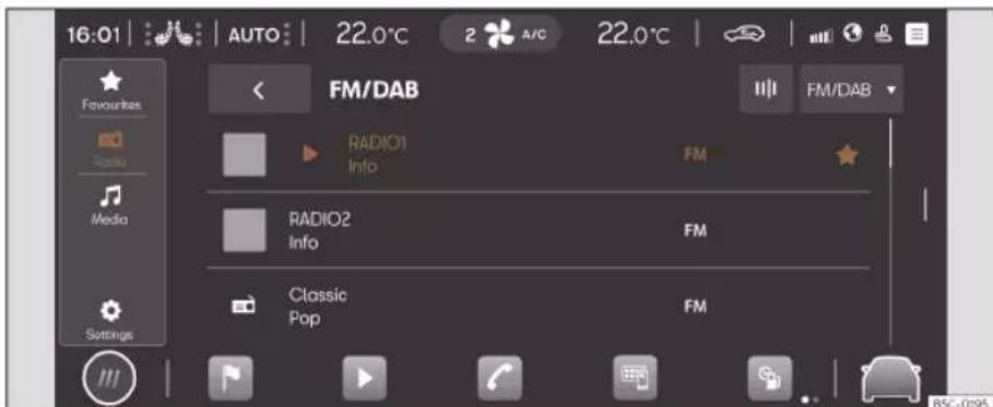
Fig. 134 Schematic representation: Radio view
In Radio mode you can tune in the available radio stations in different frequency bands and memorise your favourites on the preset buttons to access them quickly.
The types of reception and frequency bands available depend on the equipment and the country. In certain countries, frequency bands may stop broadcasting or not be available again.
Access the RADIO menu
- Press▶> Fig. 134 .
Access the settings
- Press ▶ > ⚙.
Online functions in Radio mode
Online functions in Radio mode are only available under the following conditions:
• CUPRA CONNECT or CUPRA CONNECT Plus equipment.
- You have an active CUPRA CONNECT user account.
- Add the vehicle is assigned to your user account.
- You have a corresponding data package acquired from the In-Car store or have a data volume for your own mobile phone device via Wi-Fi access point.
Note
- For streaming services you need to have an account with the provider in question.
- Radio stations are responsible for the content of the information they transmit. Additional electrical equipment connected to the vehicle can cause interference in the reception of the radio signal and noise in the speakers.
Infotainment operation
- Foil or metal-coated stickers attached to the windows may affect reception on vehicles with a window aerial.
Radio equipment and symbols
The functions, as well as the types of reception and frequency bands available depend on the equipment and the country.
• AM tuner.
• Dual FM receiver (diversity antenna).
• Summarised FM station list.
• Fusion of DAB and FM stations into one list.
- Fusion of all stations stored in preset buttons into one list. Maximum 36 favourite stations.
- Station logos.
- DAB presentation (slideshow). Images that are emitted sequentially.
- Internet radio.
Universal symbols in Radio mode
AM To select the desired AM frequency band.
FM/DAB To select the desired FM/DAB frequency band.
Online radio To select the type of Internet radio reception.
TP Next to the name of the station, monitoring of active traffic information stations (TP).
Symbols on the FM/DAB frequency band
To display the frequency band for manual selection of the FM frequency. Only possible when the summary station list is disconnected.
DAB not available.
☐ DAB stations support presentations (slideshow).
Symbols on the AM frequency band
○ Manually updating the station list.
III To display the frequency band for manual selection of the AM frequency.
Menus in Internet radio mode
:Show station selection.
Open text search.
Show the last online radio stations heard.
TOP 100 Show the 100 most played radio stations and podcasts.
Show available online radio podcasts.
Show online radio stations, grouped by country.
Show online radio stations by the desired language.
Show online radio stations whose programme belongs to the desired musical genre.
Selecting, tuning and saving a station
Select the frequency band
Before selecting a station you have to select a frequency band or a type of reception. Different stations are available depending on the frequency band selected or the type of reception.
The types of reception and frequency bands available depend on the equipment and the country.
- Select the frequency band or type of reception: AM, FM/DAB, FM (for devices that do not have DAB), Internet radio.
Search and select a station
You can select radio stations in different ways. The options vary depending on the frequency band and the type of reception.
Select via the frequency band (AM and FM)
• Activate the frequency band.
- Click on the cursor, scroll through the frequency band and release it when you reach the frequency band you want.
Infotainment system
- OR: press on a point on the frequency band. The cursor will automatically jump to the corresponding frequency.
The station of the set frequency is tuned.
Select from the station list (AM and FM/DAB)
The station list shows the stations that are currently tunable. In the AM frequency band, you may have to update the station list if you are no longer in the area where you last accessed the station list. In the FM/DAB frequency band, the station list is automatically updated.
- Open the station list
- Press the station you want.
The selected station is tuned. In the case of FM/DAB and if the station is available, the best quality reception is automatically selected.
Search and filter stations (Internet radio)
In Online Radio mode, stations can be filtered by categories and can be searched by text.
- Open the station list.
-
Select the category by which the stations are to be filtered.
-
OR: press Q to start the text search. The input field is displayed.
- Enter the name of the station you want. The list of the stations found is updated while entering the text.
- Press the station you want.
The selected station is tuned.
Search in SCAN mode (AM and FM/DAB)
In SCAN mode the stations are automatically tuned in a sequential manner and each of them is played for approx. 5 seconds.
• To start the SCAN mode press SCAN.
SCAN mode starts and the station currently tuned in is shown on the screen. Next to it is a SCAN function button.
• To select a station press SCAN.
SCAN mode stops and the station is tuned. The SCAN function button is hidden.
Storing the station on the preset buttons
You can store up to 36 stations of different frequency bands and reception types as favourites using the preset buttons.
- Tune the station you want.
- Access the preset buttons.
-
Press the preset button and keep it pressed until the station is stored.
-
OR: press the station on the station list and keep it pressed. The preset buttons are displayed.
- Press the preset button.
The station is stored in the selected preset button.
If a station was already stored in the preset button, it is overwritten with the new station.
Special functions in Radio mode
Traffic information (TP)
The TP function monitors the announcements of a station with traffic information and automatically reproduces them in the Radio mode or in the multimedia playback that is active. To do this, you have to be able to tune into a station with traffic information.
Some stations without their own traffic information support the TP function by broadcasting traffic information from other stations (EON).
In the AM frequency band or in the Multimedia mode, a station with traffic information in the background is automatically tuned while it is possible to tune into a station with traffic information.
If no station with traffic information can be tuned in, the device automatically searches for stations with tunable traffic information.
Infotainment operation
Stations with traffic information are not available in all countries.
Activating and deactivating the TP function
- In Radio mode or Multimedia mode, press Settings > Traffic station (TP).
Online radio
Online radio is a type of reception for Internet radio stations and podcasts that are independent of AM, FM and DAB. Thanks to Internet transmission, reception is not limited to the region.
Online radio is only available through the Internet connection of the active infotainment
system. The use of online radio can generate expenses due to the transmission of data from the Internet.
- In Online radio mode, press and set the audio quality to high or low to tune the online radio.
Station logos
In the case of some frequency bands, station logos may already be pre-installed in the infotainment system.
If in the FM/DAB frequency band settings the automatic selection of station logos is activated, station logos are automatically assigned to the stations.
In the Online radio mode, the infotainment system accesses the station logos of the online database and automatically assigns them to the stations
Assign station logos manually
• In FM/DAB mode, press Station logos.
- Press on the 🔔 icon and then select the station to which a station logo is to be assigned.
- Select the station logo. If desired, repeat the same process with other stations.
• OR, via the menu Settings > Station logos.
Infotainment system
Media Mode
Introduction

Fig. 135 Schematic representation: Multimedia view
In Media mode you can play multimedia files from data media and streaming services through the infotainment system.
Depending on the equipment, the following data media can be used:
• USB storage support (for example, a USB stick, a mobile phone connected via USB).
- Bluetooth® device (for example, a mobile phone or a tablet).
Depending on the equipment, the following types of multimedia files can be played:
- Audio files.
• Video files (depends on the system).
You can also use streaming services. The availability of streaming services depends on the equipment and the country.
To use streaming services you need to have your own user account in the streaming service in question.
Access the MEDIA menu
- Press ▶ > 🎯 >> Fig. 135 .
Access the settings
- Press ▶>
Limitations and indications of data media
Data media may not work if they have been exposed to high temperatures or have been damaged. Please bear in mind the manufacturer's indications.
Quality differences between data media produced by different manufacturers can cause multimedia playback malfunctions.
Incorrect configuration on a data media may cause the data media to be unreadable.
Playlists only specify a playback order and refer to the storage location of the multimedia files within the folder structure. In a playlist
Infotainment operation
there are no multimedia files saved. To play a playlist, multimedia files have to be found in the storage places of the data media to which the playlist refers.
Note
CUPRA assumes no liability for any deterioration or loss of files on data storage devices.
Features of the multimedia equipment and symbols
Audio, multimedia and connectivity:
- Multimedia playback and control via Bluetooth®.
• Audio playback in these formats: AAC, ALAC, AVI, FLAC, MP3, MP4, WMA. - Video playback in these formats: MPEG-1 and MPEG-2 (.mpg, .mpeg), ISO MPEG4, DivX 3, 4 and 5 Xvid (.avi), ISO MPEG4 H.264 (.mp4, .m4v, .mov), Windows Media Video 10 (.wmv, .asf).
• Playlists on any type of device.
• Multimedia streaming (online).
• Multimedia search.
Universal symbols in Media mode
▶ To start playback.
II To pause playback.
To change to the previous title.
To change to the next title.
Repeat the current track.
Repeat all titles.
To activate the shuffle playback order.
★ To display the favourites list.
⊕ Add multimedia file as favourite.
▼ Top right: Select multimedia source.
Access the settings.
Open the search.
To return to the top folder of the multi-media source.
Select and play a multimedia source
Select multimedia source
Before playing multimedia files you must first connect a multimedia source.
To use streaming services you must be connected to the Internet.
- Connect an external multimedia source.
- Select the connected media source to be used for playback.
Playing audio and video files
You can search and play multimedia files from an available multimedia source in different ways.
Search in the folder structure
Multimedia files can be catalogued by categories (for example, album, artist, title). In My media this category view is always displayed. The classic folder structure of individual USB data media is also found in My media.
- Activate the folder structure.
The folder structure of the selected multimedia source is displayed. When My media is selected, the categories (music, videos, playlists) and connected multimedia sources are displayed first. - Search for the title you want in the folder structure.
OR: press Q to start the text search. The input field is displayed. - Enter the name of the desired title. The list of the titles found is updated while entering the text.
- Press the desired title.
If at the beginning of the playback your selection is in a folder of a multimedia source, the multimedia files that are in it are also added to the playback.
»
Infotainment system
If a playlist is played, all available titles in the playlist are added to the playback.
- Close your selection with X.
Select favourites
In favourites you can save titles, music genres, artists and albums individually for play-back.
- Access favourites★.
- Press the favourite you want.
Depending on your selection, all the titles belonging to the favourite are added to the playback.
Configure streaming services
Depending on the equipment you can use streaming services directly through the infotainment system. For this you need to have a premium user account of the streaming service in question and you have to log in with it in the infotainment system. You also need to be connected to the Internet.
- Select ➕ Streaming as the multimedia source.
A list of available streaming services is displayed.
- Select the streaming service you want.
- Follow the steps indicated by the info-tainment system.
The streaming service is added to the list of multimedia sources as a new function button.
Save favourites
Only multimedia files in My media of the infotainment system can be saved as favourites. You can save up to a maximum of 30 titles, albums, artists and music genres individually as favourites.
- Start playback.
- Access favourites.
- Tap a favourite that is not assigned.
OR: press on an existing favourite and old for approx. 3 seconds. - Select from the selection list: Title, Album, Artist, Music genres, Playlist.
The selection is saved instead of the previously selected favourite. If the favourite was already assigned, the previously saved favourite is overwritten.
The selectable options in the selection list depend on the data attached to the multi-
media file. If the music genre is not indicated in the music files, for example, you cannot save the music genre as favourite.
If a video file is playing, only that video can be saved as favourite.
Playing entertainment content in the infotainment system
Depending on the infotainment system, videos can be played.
Video mode
When in video mode, a video can be played on the infotainment screen if this is stored on a data media, in My media or is sourced from a streaming service. In this case, the video sound is played through the vehicle's speakers.
The image is only displayed if the vehicle is stopped. When the vehicle is in motion, the infotainment screen turns off. The sound of the video can still be heard.
A stable Internet connection is required for playback from a streaming service. In this case, telephony costs may be generated.
Infotainment operation
Navigation
Introduction
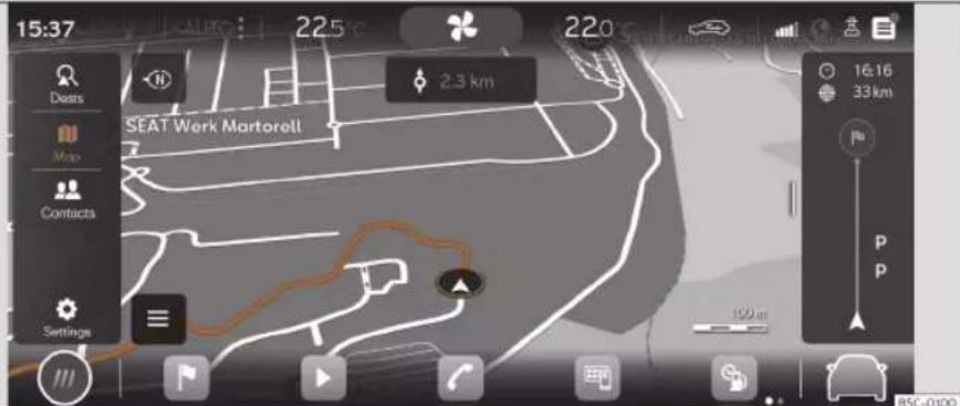
Fig. 136 Schematic representation: Navigation view
A global satellite system determines the current position of the vehicle and the sensors mounted on the vehicle analyse the routes taken. All measured values and possible traffic events are compared with the available maps to allow optimal navigation to the destination.
Navigation announcements and graphic representations will guide you to your destination.
Navigation management is carried out on the screen.
Depending on the country, some functions of the infotainment system will not be available ble on the screen when travelling above a certain speed. It is not a malfunction, but is due to compliance with legislation.
Navigation announcements
Navigation announcements are acoustic indications for driving referred to the current route.
The type and frequency of navigation announcements depend on the driving situation, for example, starting the guide to the destination, driving on the motorway or on a roundabout and the settings.
If the exact destination cannot be reached because, for example, it is in a non-digitised area, indications relating to the address and the distance to the destination are displayed on the screen.
During dynamic route guidance, you will receive information about reported traffic congestion on the route. An additional navigation announcement is provided if the route is recalculated due to traffic congestion.
While a navigation announcement is playing, its volume can be adjusted. The following »
Infotainment system
navigation announcements provided will be played with the newly adjusted volume.
Limitations during navigation
If the infotainment system cannot receive data from GPS satellites, for example, in a tunnel or in an underground garage, navigation continues using the vehicle's sensors.
In areas that are not digitised or are only partially digitised on the infotainment memory, the infotainment system will still attempt to provide route guidance.
In the case of missing or incomplete navigation data, it may not be possible to determine the exact position of the vehicle. This may mean that navigation is not as precise as usual.
Roads and streets are subject to constant change (e.g. new roads, road works, roads closed to traffic, changes to street names and building numbers). If the navigation data is obsolete, this may lead to errors or inaccuracies during the route guidance.
Managing the navigation map
To allow an optimal view, you can also manage the navigation map with additional finger movements.
Move the map (tip: use your index finger).
- Move the map with your finger.
Zoom in the view (tip: use your index finger).
- To increase the view in a certain position, double-click on the map.
Zoom out the view (tip: use your index and middle fingers).
- Press on the map with both fingers at the same time.
Change view (tip: use your index finger).
- Press twice on the map and keep your finger pressed on the screen.
- To zoom out the view of the map, move your finger upwards. To zoom in the view of the map, move your finger downwards.
Change view (tip: use your index and middle fingers).
- Press on the map with both fingers at the same time and keep them pressed.
- To zoom out the view of the map, move one finger towards the other. To zoom in the view of the map, move one finger away from the other.
Tilt the view (tip: use your index and middle fingers).
- Press on the map with both fingers at the same time and horizontal to each other, keep them pressed.
- To tilt the view of the map forward, move your fingers upwards. To tilt the view of the
map backward, move your fingers downwards.
Rotate view (tip: use your index and middle fingers).
- Press on the map with both fingers at the same time and keep them pressed.
- To rotate the map view, turn your fingers clockwise anticlockwise.
Saved data
The infotainment system saves certain data, for example, frequent routes and position data, to make the entry of the destination more agile and optimise the route guidance.
Delete saved data
- Press Settings > Basic function settings > Delete and then OK
WARNING
Select the settings, enter the destination and the modifications for navigation only with the vehicle at a standstill.
Note
- If a detour is passed during route guidance, navigation may recalculate the route.
- The quality of the navigation recommendations given by the Infotainment system depends on the navigation data available and any reported traffic congestions.
Infotainment operation
- Navigation announcements are not emitted if the sound is muted in the infotainment system.
Navigation functions and symbols
Navigation
Navigation functions depend on the equipment and country.
Functions
- Entering destination and route calculation (offline and online).
- Displaying two navigation maps at the same time (display and instrument cluster).
- Update of online maps.
- Predictive navigation.
- 3D urban maps.
• Online traffic information
• Dynamic POIs (points of interest)
Symbols on the map
The buttons and indications depend on the settings and the current driving situation.
Symbols for traffic events and points of interest (POIs) are displayed on the map, for example, petrol stations, train stations or interesting stopovers, provided navigation has such data >> page 198.
▲ Current position
Search for destinations.
Destinations along the route.
Final destination
Home address
Work address
☆ Favourite destinations
≡ Additional window with more options.
91\ Additional window with route options.
Centre the map on the current position.
Change view: 2D oriented to the north, or 2D oriented to the direction of travel, or 3D to the direction of travel.
Information about the current route guidance.
500m Map scale.
Symbols in the additional window
- To open the additional window, press三.
Repeat the last navigation announcement.
Volume of navigation announcements. - Map lighting in Automatic, Day or Night mode.
Offer new guidance routes.
Elü 360° electric range indicator (hybrid vehicles)
Other symbols
Entering the detailed destination for an address.
Search for destinations.
Frequent destinations.
Last destinations.
☆ Favourite destinations
< Back
Symbols in the route details
△ Current position.
Destination of the current guidance.
POI symbols (points of interest)
POIs (points of interest) are shown on the map, provided the navigation has said data. Click on the desired POI (point of interest) to start a route guidance» page 196.
Petrol station.
P Parking lot.
i Tourist information offices.
Train station.
41 Restaurant.
Traffic information.
POIs (points of interest) are shown on the map, provided the navigation has said data >> page 198.
》
Infotainment system
Click on a traffic event to open an additional window with further details>>> page 198.

Slow traffic.

Traffic jam.

Accident.

Broken down vehicle.

Slippery surface (ice or snow).

Road closed to traffic.

Slippery road hazard.

Danger.

Road works.

Strong wind.

Reduced visibility.
Navigation data
The Infotainment system is equipped with a built-in navigation data memory. Depending on the country, the necessary navigation data may already be pre-installed.
To provide correct route guidance and make the most of the functions offered, the info-tainment system should be updated on a regular basis.
Using obsolete data may lead to errors during navigation. Current routes cannot be traced or the route guidances will lead to mistaken destinations.
Ensure navigation data is updated at all times.
Online updating of navigation data
The navigation data of the regions through which you travel frequently is automatically updated in the background if the Internet connection is established and the privacy settings are valid.
- With the ignition switched on, the navigation data is updated automatically.
Manual update of navigation data
Current navigation data for large regions, for example Western Europe, can be downloaded from www.seat.com and stored on USB data devices. Navigation through USB data devices is not possible.
- Download the navigation data to a USB data device.
- Turn on the ignition of the vehicle.
- Connect the USB data device to the infotainment system. Navigation data is automatically updated in the background.
The map version is displayed in Ⓧ Settings > System information.

WARNING
If you update the navigation data manually while driving, it may cause accidents with serious injuries.
- Update the navigation data only with the vehicle at a standstill.

Note
Automatic update of the navigation data is subject to the privacy settings. In "Incognito" mode, no update is carried out.
Start route guidance
Depending on the country and equipment, different functions are available to enter destinations.
The different functions for entering destinations are found in the navigation main menu.
Opening the Navigation main menu
- Press|Navigation.
Select the destination and start navigation
- Press
- Select the desired destination. You can choose from ⚙ Frequent destinations, ⏱ Last destinations and ☆ Favourite destinations.
Infotainment operation
OR: press Q and enter the address in the input screen.
OR: detailed address.
- Press Start.
Frequent destinations
The destination synopsis uses recorded data to propose possible destinations.
Select the destination and start navigation
- Press 🔒 and then 🔒.
- Select the desired destination. The route guidance starts automatically.
Quick start: for a quick start, press and hold the desired destination for a few seconds.
Last destinations
Navigation saves the last destinations to make them available for a route guidance.
Select the destination and start navigation
- Press ▲ and then Ⓤ
- Press the desired destination.
- Press Start.
Quick start: for a quick start, press and hold the desired destination for a few seconds.
☆ Favourite destinations
Save up to 20 destinations as favourites.
To save a destination as a favourite press ☆ in the split screen when entering the destination.
Select the destination and start navigation
- Press 🔒 and then ☆.
- Press the desired destination.
- Press Start.
Note
Enter the destination as accurately as possible. If you enter a destination incorrectly, the route guidance will not be able to start or it will guide you to an incorrect destination.
Start route guidance by selecting from the map
The navigation map includes active areas at many points that are suitable for entering the destination. To do this, press the desired position or place on the map. If there is map data at this point, you can start a route guidance.
Whether it is possible to enter the destination through the navigation map depends on the state of the data and it is not possible for all positions.
To start "offroad navigation", press an empty area without position data.
Start navigation
- Press 📄.
- Move the view on the map until the desired position can be selected. The navigation map can be used by means of additional finger movements»» page 194.
- Press the desired destination on the map.
- Press Route.
Offroad navigation
"Offroad navigation" calculates routes to selected destination points using unknown data. When a destination point is outside the known roads or position data, navigation finds the route to the next point of the known road and completes the path to the next destination point with a direct connection.
Start navigation
- Move the view on the map until the desired position can be selected. The navigation map can be used by means of additional finger movements»» page 194.
- Press on any point on the map without position data.
- Press Route.
Infotainment system
Start route guidance using contact details
Start route guidance with the saved address data of a contact. Contacts saved without address data cannot be used for route guidance.
Start navigation
- Press
- Press on the contact you want.
- Press Route.
Note
If the address details of a contact are obsolete, the route guidance will nevertheless take you to the registered address. Check that the contact address is updated.
Traffic information
The infotainment system receives detailed traffic information automatically if the Internet connection is established. This information is shown with symbols and highlighting the road network in colour on the map.
Traffic incidents
Traffic incidents, for example, traffic jams or congested traffic, are shown on the navigation map using symbols.
With an active route guidance, traffic incidents that are on the current route are shown in the route details. Such traffic incidents can be avoided» page 198.
Hazard information
Hazard information is shown on the navigation map with symbols in the same way as traffic incidents. In this case, the source of this information is another vehicle that has detected the hazard and has uploaded the information to the service provider.
The hazards shown are: accident, broken down vehicle and slippery road surface.
Traffic flow indication
The navigation map shows traffic flow according to current traffic events, highlighting the road network in colour.
- Orange: Slow traffic.
- Red: Traffic jam.
Note
Traffic information receipt is subject to the privacy settings. In maximum Privacy mode, no traffic information is received. Tracking or Location level setting is necessary.
Function descriptions
Route details
The route details contain information on all incidents, for example, the starting point, stopovers, traffic events, POIs and destination, provided the navigation has such data.
If you press on an incident, an additional window opens providing more options. The available options depend on the incident and the current settings.
Open and close the route details
• To open, press | or swipe it.
- To close, press | or swipe it.
Edit route guidance
To edit route guidance, move the stopovers to the destination in the TripAdvisor view.
- Hold the desired destination pressed until it is visibly highlighted.
- Move the destination to the desired position.
- Remove your finger from the screen. The route will recalculate.
Avoid traffic incidents
The details of the route show the current traffic incidents if the navigation has such
Infotainment operation
data. Avoid traffic incidents by editing route details>>> page 198.
- Press on a traffic event.
- Press on Avoid. The route will recalculate.
Split screen
When handling navigation functions, an additional window with other options may open. Possible options depend on the function being used.
Close the additional screen
- Press on an empty area outside the additional window.
- OR: press X.
- OR: press Accept.
Functions in the additional window:
| Show on map Show what is selected on the map. |
| Add stopover Add a stopover to the route guidance. |
| Direct route Starts direct route guidance. |
| Delete Delete a stopover from the route guidance. |
| Avoid Avoid traffic jam. The route will re-calculate. |
Functions in the additional window:
| Stopping route guidance | Ends the current route guidance. |
| ✕ | Close the additional window. |
| ☆ | Add a destination to favourites. |
Learn usage pattern
When the vehicle is in motion, navigation saves routes and destinations used to automatically generate destination proposals. Destinations are learned based on the time of day and the day of the week.
Navigation can propose up to 5 routes at the same time. The proposed routes may be different from the routes of the normal route guidance.
If one of the proposed destinations is selected, the guide to that destination is started.
The route guidance follows the selected route until the vehicle deviates from it. In that case, the route is recalculated and takes you back along the most direct path to the initially selected destination.
Important traffic jams are taken into account in the route guidance, and are avoided if alternative routes are available, provided navigation has such data.
You can activate and deactivate the function whenever you want.
Enable and disable learning usage pattern
The setting is in the corresponding navigation menu ⚙ > Basic function settings.
- To activate the function, activate Learn usage pattern.
- To disable the function, disable Learn usage pattern.
- To delete saved data, press Delete usage pattern.
360° electric range display
√ Valid for: plug-in hybrid vehicles
The 360° electric operating range display shows the possible range with the current charge level of the high voltage battery.
Switch on the 360° electric operating range display
- Open the additional map window and press the symbol 📁.
Infotainment system
Telephone interface
Introduction

Fig. 137 Schematic representation: Phone view
You can use the telephone interface to connect your mobile to the infotainment system and operate phone functions through it. The sound is played through the vehicle's speakers.
You can connect up to two mobile phone devices simultaneously to the infotainment system.
High speeds, poor weather or road conditions and a noisy ambience (even outside of the vehicle), as well as the quality of reception can all affect the quality of a telephone conversation in the vehicle.
Note
- As a general rule, pairing a device (for example, a mobile phone device) is only necessary once. You can restore the device connection via Bluetooth® or Wi-Fi with the infotainment system whenever you want without having to pair the device again.
- The availability of some telephone functions will depend on the mobile phone connected to the infotainment system.
Telephone interface equipment and symbols
Equipment features
- Hands-free function.
• Use up to two phones at the same time. - Phone book with a maximum of 5,000 contacts.
- SMS functions via Bluetooth®: SMS reading, SMS writing (templates included), SMS playback, message history.
- Email functions via Bluetooth®: reading email, writing email.
Infotainment operation
- Connection to wireless charging option.
- Connection to the microphone mounted on the vehicle.
Symbols in the main menu
Contacts.
List of incoming and outgoing calls.
Enter telephone number.
Text messages (SMS and emails).
Telephone interface settings.
Symbols for calls
The symbols may be different depending on the infotainment system.
Start a call or bringing it to the fore-ground.
End or reject a call.
Open contact list.
Enter telephone number.
Mute the sound of the hands-free
Hold call.
Continue call.
Start conference call.
Pass call to private mode
SOS Make an emergency call.
Get help in case of breakdown.
i Obtain information on the CUPRA brand and selected additional services related to traffic and your travel.
○ Voice mail.
Call list symbols
• To open the call lists, press
Incoming call.
Outgoing call.
Missed call.
Telephone number (company).
Telephone number (private).
Mobile telephone number (company).
☐ Mobile telephone number (private).
Fax (private).
Fax.
Symbols for text messages
The symbols may be different depending on the infotainment system.
• To open the text messages, press
Ω0 Activate voice control input >> page 184.
Templates for text messages.
Places with special regulations
Switch off the mobile telephone and the telephone interface in places with a risk of explosion. These places are not always clearly marked. They include, for example:
- The vicinity of chemical pipelines and tanks.
• The lower decks of boats and ferries. - In the proximity of vehicles that run on liquefied gas (such as propane or butane).
- Places where the air is laden with chemicals or particles such as flour, dust or metal powder.
- All other places where the vehicle engine or telephone must be switched off.
WARNING
Switch off the mobile phone in areas with a risk of explosion!
Note
In areas where special regulations apply or the use of mobile phones is forbidden, it must be switched off at all times. The radiation produced by the mobile phone when switched on may interfere with sensitive technical and medical equipment, possibly resulting in malfunction or damage to the equipment.
Infotainment system
Pair, connect and manage
Requirement for pairing:
- Bluetooth® is activated on the mobile phone device.
- Bluetooth® is activated on the infotainment system.
- Depending on the mobile device, it will be necessary to have the Bluetooth® menu open or activate the Visibility option so that the device is visible from the infotainment system.
Pair a mobile phone device suitable for telephony with the infotainment system to use the telephone interface functions. On the first connection, the mobile phone device is paired with the infotainment system. Doing so saves a user profile» page 202.
The pairing can take a few minutes. The functions available depend on the mobile phone device used and its operating system.
Pair a mobile phone device
- Open the list of available Bluetooth® devices on the mobile phone device and select the name of the infotainment system.
- Please note and, if necessary, confirm the messages that appear on the mobile phone device and on the infotainment system. If the pairing was successful, the phone data is saved in the user profile.
- Optional: confirm the data transfer message on the mobile phone device.
Active and passive connection
To use the functions of the telephone interface, there must be at least one mobile phone device connected to the infotainment system. If there are several mobile phone devices connected to the infotainment system, you can switch between active and passive connections. To use the telephone interface with the desired mobile phone device, establish the active connection with the infotainment system.
Difference between connection types
| Primary | The mobile phone device is paired and connected. The functions of the telephone interface are performed with the data of said mobile phone device. |
| Secondary | The mobile phone device is paired and connected. Calls can be managed but the phone book, messages or other functions will not be active. |
Paired mobile phone devices are stored in the infotainment system, even if they are not currently connected.
Connect a mobile phone device
Requirement: the mobile phone device is paired with the infotainment system.
- Bluetooth® is activated on the mobile phone device.
Establish an active connection
Requirement: several mobile phone devices are connected to the infotainment system at the same time.
- Select the desired mobile phone device from the drop-down menu. All other mobile phone devices are automatically in the passive connection.
User profiles
For each of the paired mobile phone devices an individual user profile is automatically created. In the user profile, data from the mobile phone device is stored, for example, contact details or settings. A maximum of four user profiles can be saved in the infotainment system at the same time.

WARNING
If you perform the pairing while driving, it could cause an accident or injury.
- Perform pairing only with the vehicle at a standstill.
Infotainment operation
Note
- In the pairing of some mobile phone devices, a PIN number is shown on the screen of the mobile phone device. Enter that number in the infotainment system to complete the pairing.
- While the infotainment system is in the Known mobile phones menu, the wireless charging function is disabled. When you exit this menu, the wireless charging function is activated again.
Basic and Comfort Telephony
Depending on the equipment, two types of telephone interface can be used:
• Basic telephone interface.
• Comfort telephone interface.
Basic telephone interface
The Basic telephone interface uses the Bluetooth® HFP profile for transmission. This interface allows the use of telephone functions through the infotainment system and playback through the vehicle's speakers.
Comfort telephone interface
Like the Basic telephone interface, the Comfort telephone interface also uses the Bluetooth® HFP profile.
The Comfort phone interface can be equipped with the wireless charging function >> page 204.
In order to use the functions of the wireless charging function, you have to place a suitable mobile phone device correctly in the storage compartment. The mobile phone device will then connect to the vehicle antenna. This improves the reception and sound quality of calls.
To call
Open the telephone interface
- Press ↗ Telephone.
Make a call
Select a phone number to start a call. Different functions are available for selecting a phone number:
Contacts
If a contact has several registered phone numbers you have to select one.
- Press 🎯 and press a number on the list to start the call.
- OR: press Q and enter the contact name in the input field to search for it. Press on the contact to start the call.
- OR: press a favourite in the telephone interface main menu to start the call.
Calls
The telephone interface shows the call list of the mobile telephone device. Start a call from the call list.
- Press > All and press a number on the list to start the call.
- OR: press ↩ and filter the call list entries (for example, missed calls or dialled numbers). In filtered list, press a number to start the call.
Dial
Manually enter a phone number to start a call. While entering the phone number, contacts that match that number are shown on the infotainment screen.
- Press and enter telephone number.
- Press ↗ to start the call
The last call is dialled by pressing and holding the button on the multifunction steering wheel.
Send messages
Depending on the mobile phone device and the infotainment system used, you can send »
Infotainment system
and receive SMS and e-mails through the telephone interface.
Send an SMS
- Press 📋 > Text message > Enter new message and enter the message on the screen.
- Enter the contact you want in the search bar.
• To send the message press OK.
Send an e-mail
- Press > E-mail > Enter new message and enter the message on the screen.
- Enter the contact you want in the search bar.
• To send the message press OK.
Phone book, favourites and speed dial buttons
In the first connection of a telephone with the infotainment system, the phone book is saved in the infotainment system. It may be necessary to confirm the data transmission on the mobile phone.
Each time the phone is reconnected, the phone book is updated.
If conference calls are supported, the phone book can be accessed during a call. If there is a saved image for a contact, it can be displayed in the list next to the entry.
Favourites
A speed dial button can be assigned to a phone book favourite up to a maximum of six. If there is a registered photo saved to the contact, it is shown on the speed dial button.
All speed dial buttons have to be manually edited and will be assigned to a user profile.
Assign the speed dial button
- In the Favourites menu, press the + button, then open the phone book to select a contact as a favourite. If the contact has several phone numbers, press on the number in the list.
Edit the speed dial button
- To edit or delete a favourite contact press on the icon in the Favourites menu screen. You can delete one or more favourites.
Call a favourite
- Press the assigned speed dial button.
Note
Favourites are not updated automatically. If you change a contact's phone number, you have to reassign the speed dial button.
Connectivity Box

Fig. 138 In the centre console: pad for the mobile phone connection.
The Connectivity Box includes different functions that will help to use your mobile device. These are:
- Wireless Charger 1) .
Infotainment operation
• Signal amplifier / (Mobile Signal Amplifier)
(Wireless Charger)
The Wireless Charger allows mobile devices with Qi 1) technology to be charged without a cable.
To charge your mobile phone wirelessly:
- Place your mobile device in the middle of the pad with the screen facing up»» Fig. 138 »» △.
Make sure there are no objects between the pad and the mobile phone.
The mobile phone will start charging automatically. For further information about whether your mobile device supports Qi technology, check your phone's user manual or visit the CUPRA website.
Signal amplifier / (Mobile Signal Amplifier) It allows you to reduce radiation in the vehicle and have better reception.
For safety reasons, it is recommended that you pair the system and the mobile using Bluetooth ® and place it on the Connectivity Box pad, for the best reception without having to handle the mobile phone.
To establish a connection with the vehicle's external aerial:
- Place your mobile device in the middle of the pad with the screen facing up>> Fig. 138
Make sure there are no objects between the pad and the mobile phone.
Your mobile phone will automatically be ready to make use of the external aerial.
WARNING
Notifications on the screen of the mobile phone device can distract the driver's attention and increase the risk of a serious accident.
- Place only one suitable mobile phone device, Qi compatible if applicable. For correct operation, remove the protective case and ensure that it has maximum dimensions (width x length) of 80 mm x 140 mm (3.15 x 5.512 inches). Place on the Connectivity Box base as per the indications.
- If the mobile phone device is not placed on the base of the Connectivity Box in the correct position, or if it is larger than the detailed dimensions, it may not be recognised or charge correctly. Under certain
circumstances, the infotainment system indicates that there is a foreign object in the storage compartment. Using a suitable mobile phone device and correcting its position can eliminate the fault.
- If necessary, remove any objects that may obstruct the cover's closing function.
WARNING
- The mobile phone may heat up due to the wireless charging. Think about this before you pick it up, and take care when removing it.
- There must be no metallic or other objects between the mobile phone and the housing, to prevent the functionality of the Connectivity Box from being affected.
Note
- Your mobile device must support the Qi inductive charging interface standard for proper operation.
- The charging time and the temperature vary in accordance with the device used.
• The maximum charging capacity is 5 W.
- Qi technology does not allow you to charge more than one mobile device simultaneously.
Infotainment system
- No improvement in reception can be guaranteed if there is more than one mobile phone on the pad.
- You are advised to keep the engine running to guarantee proper wireless charging.
- When a telephone with Qi technology is connected by USB, it will be charged by the means specified by the manufacturer.
Multimedia
USB port

Fig. 139 Centre console: USB port.

Fig. 140 Rear part of the centre console: USB connectors with power outlet function.
The USB port can be found in the storage compartment area of the front centre console>>> Fig. 139.
Depending on the equipment and the country, the vehicle may also have USB connections exclusively for charging or as a power socket.
These USB ports are located at the rear of the console, between the front seats >> Fig. 140.
Start and driving
Driving
Start and driving
Starting and stopping the engine
Ignition and start button

Fig. 141 Starter button
The engine can be started with a start button (Press & Drive). For this there must be a valid key inside the passenger compartment.
The START ENGINE STOP button is found at the bottom of the centre console or, depending on
the version, on the multi-function steering wheel.
Opening the driver's door when exiting the vehicle activates the electronic lock on the steering column if the ignition is disabled.
Switching the ignition on/off
If you only want to switch on the ignition (without starting the engine), briefly press the start button once without pressing the brake pedal or the clutch pedal» △.
The START ENGINE STOP push-button text flashes like a heartbeat when the system is ready for the ignition to be turned on or off 1) .
Automatic ignition disconnection
When the vehicle detects that there is no driver once the engine has stopped, after a certain time the ignition is switched off automatically. If at that time the dipped beam headlights are on, the side lights will stay on for approx. 30 minutes. The side lights can be turned off by blocking the vehicle >> page 97, or manually >> page 115.
Automatic deactivation of the ignition on vehicles with the Start-Stop system
The ignition is switched off automatically when the vehicle is stopped and the automatic engine shutdown is active, if:
• The driver's seat belt is not fastened,
• the driver does not step on any pedal,
• the driver door is opened.
After automatically turning off the ignition, if the dipped beam is on, the side light remains on for approx. 30 minutes (if there is enough charge in the battery). If the driver locks the vehicle or manually turns off the light, the side light goes out.
Switching off the ignition when leaving the vehicle, with hybrid drive
When the ignition is not switched off in E-MODE operating mode, a certain amount of time after the journey is complete it switches off automatically to prevent draining the 12-volt vehicle battery.
"My Beat" function 1)
For vehicles with a convenience key there is the "My Beat" function. This feature provides »
Driving
an additional indication of the vehicle ignition system.
When entering the vehicle, the start button >> Fig. 141 flashes to draw attention to it.
When the ignition is on/off, the engine start button flashes. With the ignition is switched off, the start button goes off after a few seconds.
With the engine running, the start button light stays on, indicating that the engine is running. The time elapsed between the moment the user starts the engine with the start button and the lighting changes from flashing to fixed will depend on specific engine size characteristics. When the start button is used to stop the engine, the button starts flashing again.
In vehicles with the Start-Stop system, the "My Beat" function also offers additional information:
- When the engine stops during the Stop phase, the light of the start button stays on, as the Start-Stop system remains active even though the engine is off.
- When the engine cannot be started again with the Start-Stop system,»» page 215, and needs to be started manually, the start button flashes to indicate this situation.
WARNING
When switching on the ignition, do not press the brake or clutch pedal, otherwise the engine could start immediately.
WARNING
If vehicle keys are used negligently or without due care, this may cause accidents and serious injury.
- Never leave any key inside the vehicle when you leave it. Otherwise, a child or unauthorised person could lock the vehicle, start the engine or connect the ignition and operate any of the electrical equipment.
Note
- Before leaving the vehicle, always disconnect the ignition and, if appropriate, take into account the instructions on the screen of the dash panel.
- If the vehicle is stationary for a long time with the engine off and the ignition on, the vehicle battery might be discharged and it might not be possible to start the engine.
-
In vehicles with diesel engines, wait until the warning light 00>>> page 208 goes off before starting the engine.
-
If during the STOP phase you press the START ENGINE STOP button, the ignition is switched off and the push-button flashes 1 .
- If the indication is displayed on the instrument panel display "Start-Stop system deactivated: Start the engine manually"; the START ENGINE STOP button will flash 1 .
Starting the engine
• Vehicles with manual transmission: put the gear lever in neutral, press the clutch pedal and keep it pressed in this position until the engine starts.
• Vehicles with automatic transmission: press the brake pedal and keep it pressed in this position until the engine starts.
- Press the starter button>> Fig. 141; do not press the accelerator. There needs to be a valid key inside the vehicle for the engine to start. After starting the engine, the lighting of the STARTENGINESTOP button remains fixed indicating that the engine is running 1 .
- Once the engine starts, release the start-up button.
Start and driving
- If the engine does not start, stop and wait for around 1 minute to try again. If necessary, perform an emergency start»» page 210.
Diesel engines can take a few seconds longer than usual to start on cold days. During preheating, the warning lamp ☑ remains lit. To avoid unnecessary discharging of the battery, do not use any other major electrical equipment while the glow plugs are preheating.
The preheating time depends on the coolant and exterior temperatures. With the engine at operating temperature, or at outside temperatures above +8°C, the warning lamp will light up for about one second. This means that you can start the engine almost immediately.
Starting a diesel engine after having run out of fuel
If the fuel tank of a diesel vehicle was run until completely empty, after refuelling it can last longer than normal to start the engine, even up to a minute. This is because the fuel system must eliminate air first.
WARNING
Do not keep the engine running in confined spaces, as there is a risk of poisoning.
- The exhaust gases contain carbon monoxide, an odourless and colourless poison-
ous gas that can cause loss of consciousness and death.
WARNING
Do not get out of the vehicle with the engine running, especially if a gear is engaged. The vehicle could then suddenly move or something strange could happen that would cause damage, fire or serious injury.
WARNING
Never use cold start sprays, they could explode or cause the engine to run at high revs. Doing this risks injury.
CAUTION
• The starter motor or the engine may be damaged if you try to restart the engine immediately after switching it off.
- When the engine is cold, you should avoid high engine speeds, driving at full throttle and over-loading the engine, as this could cause engine damage.
For the sake of the environment
Do not warm-up the engine by running the engine with the vehicle stationary. Start off immediately, driving gently. This helps the engine reach operating temperature faster and reduces emissions.
Note
- Electrical components with a high power consumption are switched off temporarily when the engine starts.
- When starting with a cold engine, noise levels may briefly increase. This is quite normal, and no cause for concern.
- When the outside temperature is below +5 °C (+41 °F), if the engine is diesel, some smoke may appear under the vehicle when the fuel-operated auxiliary heater is on.
Turning off the engine
- Bring the vehicle to a full stop»»
- With manual transmission, press the clutch all the way down. If fitted with an automatic gearbox, activate the parking lock by pressing button P.
• Apply the electronic parking brake. - Briefly press the start-up button
Fig. 141.
Car wash function (hybrid vehicles)
When the ignition is turned off with gear N activated, the vehicle can roll for the next 30 minutes. After that time, if the vehicle is stopped the parking lock P activates automatically. The corresponding warning message is displayed on the instrument cluster display one minute before this happens.
Driving

WARNING
Never switch off the engine while the vehicle is moving. This could cause loss of control of the vehicle, accidents and serious injury.
• The airbags and belt tensioners do not work when the ignition is switched off.
• The brake servo does not work with the engine off. Therefore, you need to press the break pedal harder to brake the vehicle.
- Power steering does not work when the engine is not running. You need more strength to steer when the engine is switched off.
- If the ignition is switched off, the steering column could be locked, making it impossible to control the vehicle.

WARNING
Always take the key with you when you leave the vehicle. This is particularly important if there are children in the vehicle, as they might otherwise be able to start the engine or use power-operated equipment (e.g. the electric windows), which could cause injuries.

CAUTION
- If the vehicle is stopped and the Start-Stop system switches off the engine, the ignition remains switched on. Make sure that the ignition is switched off before leaving
the vehicle, otherwise the battery could discharge.
- If the engine has been driven at high speed for a prolonged period of time, it may overheat when switched off. To avoid damage, allow the engine to run for approximately two minutes in neutral before switching it off.

Note
After the engine is switched off the radiator fan may run on for up to 10 minutes, even if the ignition is switched off. It is also possible that the fan turns itself on once more if the coolant temperature increases due to the heat accumulated in the engine compartment or due to its prolonged exposure to solar radiation.
Electronic immobilizer
The electronic immobiliser prevents unauthorised persons from driving the vehicle.
In the key there is a chip that automatically deactivates the electronic immobiliser.
The electronic immobiliser is automatically activated when the key is outside the vehicle.
If the following message is shown on the instrument panel display: SAFE, the vehicle cannot be started.
The engine can only be started using a genuine CUPRA key with its correct code.

Note
A perfect operation of the vehicle is ensured if genuine CUPRA keys are used.
Emergency starting function
Fig. 142 In the centre console: emergency start.
If no valid key is detected inside the vehicle, an emergency start-up will be required. The relevant message will appear in the dash panel display. This may happen when, for example, the vehicle key battery is very low:
Start and driving
- Immediately after pushing the start button, place the key in the drink holder of the centre console>> Fig. 142, as close as possible to the Kessy logo.
- The ignition connects and the engine starts automatically.
Instructions for the driver on the instrument panel display
Depress the clutch
- This indication is displayed on vehicles with a manual gearbox when the driver does not depress the clutch pedal when starting the engine. The engine can only be started if the clutch pedal is depressed.
Press the brake
- This message appears on vehicles with an automatic gearbox if the driver tries to start the engine without having the brake pedal pressed.
Press the brake to engage a gear
- This indication is displayed when starting or stopping the engine if the automatic transmission selector lever is in position D or R and the brake pedal is not depressed. The engine can only be started and stopped in these positions.
Move the selector lever to P; the vehicle can move; the doors can only be locked in P
- For safety reasons, this driver message appears and an audible warning sounds if the parking lock button P is not pressed after switching off the engine. Press button P otherwise the vehicle could move.
Ignition is switched on
- This driver message is displayed and a buzzer is sounded when the driver door is opened with the ignition switched on.
Driving with electric drive
Switching on the hybrid drive system
√ Valid for: hybrid vehicles
Switching on the hybrid drive activates the vehicle's propulsion system. When the vehicle's drive system is switched on, the electric drive is activated. The combustion engine starts automatically when the charge level of the high-voltage battery is not sufficient to run with the electric drive, or if high drive power is required.
To access driving with the electric drive in the infotainment system:
- > Vehicle > Exterior > Electric drive.
Requirements for switching on the drive system
The drive system can be switched on when the following conditions are met:
- The high voltage battery has a sufficient charge level.
• There is no charging cable plugged in. - The temperature of the high-voltage battery is within the operating range.
- There is a valid remote control key in the vehicle.
Switching on the drive system
- Press the ignition and start button once. The ignition must be switched on.
- Press the brake pedal and keep it pressed.
- Set the gear selector switch to position N or activate the parking lock P.
- Press the ignition and start button
Fig. 141 until indicator lamp READY lights up on the instrument cluster. Do not press the accelerator. Release the ignition and start button when the indicator lamp READY lights up on the instrument cluster. The mark on the power display changes from OFF to 0.
»
Driving
- If the indicator lamp READY does not light up, cancel and repeat the operation.
- If the vehicle has been locked with the remote control key, the ignition and start button is deactivated. If you are inside the vehicle and have to start the engine, first unlock the vehicle or perform an emergency start »» page 210.
Detecting the drive system
With the electric drive, the motor makes no noticeable noise when the drive system is switched on or while driving. Therefore, you cannot defect that the vehicle's drive system is on by engine noise. Instead, the following characteristics show that the vehicle is ready to drive:
- The power display on the instrument cluster displays 0>>> page 77.
- The display light on the instrument cluster is on, regardless of whether the vehicle's exterior lighting is on.
• The indicator lamp on the instrument cluster switches on READY.
• An audio signal is heard.
Switching on the drive system in very low outside temperatures
If the outside temperature is very low (approximately -27°C (-16°F) or lower), the high-voltage battery may freeze and stop working. In this case it's not possible to switch on the drive system.
As soon as the temperature of the high-voltage has increase enough, the drive system can be switched on again.
To ensure that the drive system can be switched on, even in very low outside temperatures, CUPRA recommends parking the vehicle in a place protected from the cold.
Note
A click is heard when the drive system is turned on. This is completely normal and does not mean there is a problem.
Vehicle sound
√ Valid for: hybrid vehicles
The electric drive makes much less noise than a combustion engine. In the versions for some countries, artificial vehicle sound is generated to allow the vehicle to be heard better from the outside. At higher speeds, when the noise produced by the tyres and the wind increases, the vehicle's sound automatically fades out.
WARNING
During electric driving, the auditory perception of the vehicle by other road users may be much lower. This is especially true
in traffic-restricted areas and when manoeuvring or reversing. Accident hazard!
Troubleshooting
√ Valid for: hybrid vehicles
Drive: Fault! Stop the vehicle safely
The warning lamp lights up red.
There is a fault in the vehicle's drive system. The vehicle's drive system is no longer available. Park the vehicle in a safe place as soon as possible. Seek professional assistance.
Drive: Fault! The electric drive is not working properly. Visit a workshop
The warning lamp lights up yellow.
There is a fault in the vehicle's drive system. Drive slowly to a specialised workshop to have the fault repaired.
Drive: Warning! Power is limited. Check the manual
The warning lamp lights up yellow.
Performance limited. The high-voltage battery may not be sufficiently charged or may have reached its operating temperature limit, for example in very cold outside temperatures.
Start and driving
Vehicle sound: Fault! Pedestrians cannot hear the vehicle. Visit a workshop
The warning lamp lights up yellow.
There is a vehicle sound fault. Drive with utmost care, as other road users may not be able to hear the electric vehicle. Go immediately to a specialised workshop to have the fault repaired.
Operating mode selection
Operating mode selection
√ Valid for: hybrid vehicles
The vehicle has different operating modes so that it can always be optimally adjusted to every situation while driving. Once the drive system has been turned on, and provided that all of the operating conditions required for this purpose have been met, the E-MODE operating mode is always activated in the first instance for electric driving.
Operating mode selection
- Switch on the drive system»» page 211.
- Press button ⚙️ on the control panel of the upper centre console.
- Press the E-Mode or Hybrid function button in the infotainment system.
Further information about the operating mode can be found in ⓘ.
E-MODE (electric driving) 1)
In the E-MODE electric driving mode, the vehicle basically drives in electric only mode. To the extent possible, the vehicle's combustion engine is not used.
All of the following conditions must be met for E-MODE to be activated:
- The high voltage battery has a sufficient charge level.
- The vehicle speed is lower than 130 km/h (80 mph).
- The high voltage battery temperature is above -10°C .
If, while driving in E-MODE mode, the necessary conditions are no longer met, the combustion engine starts and electric driving is suspended. In this case, the display Ⓞ lights up on the instrument cluster display.
The combustion engine starts when a kick-down occurs in E-MODE. However, E-MODE remains activated.
Hybrid ☐ (use the battery's charge) 1)
This is the operating mode that allows you to save most fuel.
The operating mode control unit tries to make the most of the battery charge. For this purpose, with active directions the navigation data are also accessed.
In this operating mode, the electric motor and the combustion engine share the work of driving the vehicle.
In hybrid operating mode, the power from the battery charge is used optimally. If route guidance is activated, the vehicle may autonomously recharge the high-voltage battery using the combustion engine.
Manual control of the battery charge
Manual control of the battery charge is only possible in Hybrid operating mode. The option selected by the user is only valid until the ignition is switched off or the vehicle is switched to Hybrid mode or E-MODE.
Driving
Press the function button ⚙ and use the symbols >, = and < to control the battery charge:
Pressing this symbol selects a higher theoretical charge level. The vehicle tries to reach that new theoretical high-voltage battery charge level while driving. The vehicle is powered by the combustion engine. If the combustion engine has "excess" power, it is used to charge the high-voltage battery. This option increases fuel consumption. CU-PRA therefore recommends using the charging socket to charge the high-voltage battery, whenever possible >> page 306.
= The high-voltage battery charge level is kept at around the current level while driving. If you accelerate harder or increase the vehicle speed, the combustion engine starts up. When permitted by the driver's demand for acceleration and the vehicle speed, the vehicle switches back to electric mode.
< Pressing this symbol selects a lower theoretical charge level. The vehicle only uses the battery's charge when it is above the selected theoretical charge level. The rest is kept until the end of the journey.
The Intelligent Hybrid App allows the user to save electrical energy until reaching home (charging point) with just "one click". If this option is not selected, the maximum amount of electrical energy will be consumed until the selected destination is reached. If the user has no active route, the function will offer the activation of a predictive route and BMA mode from the widget itself with just one click.
Show the active operating mode
The operating mode active at any given time is displayed on the instrument cluster display, e.g.
WARNING
Switching to a different operating mode while driving can distract you from traffic conditions and cause accidents.
Note
Information about the operating mode that is currently active is displayed on the instrument cluster display, along with the charge level of the high-voltage battery.
Troubleshooting
(E) The E-MODE operating mode is not available
The indicator lamp lights up in white.
The E-MODE operating mode (driving in electric mode) cannot be used temporarily because one or more conditions are not met.
- The conditions must be met to use the E-MODE operating mode»» page 213.
Start-Stop system
Control lamps
(A) It lights up
The Start-Stop system is available, the automatic engine shutdown is active.
It lights up
The Start-Stop system is not available or has been disconnected.
Start and driving
Instructions for the driver on the instrument panel display
Start-Stop system deactivated. Start the engine manually
- This indication for the driver shows that the Start-Stop system cannot start the engine again.
Start-Stop system: Fault! Function not available
- There is a fault in the Start-Stop system. Take the vehicle to a workshop to have the fault repaired.
Description and operation
The Start-Stop system helps you to save fuel and reduce CO2 emissions.
In Start-Stop mode, the engine will automatically switch off when the vehicle stops or is stopping. The ignition remains switched on. The engine automatically switches back on when required.
In this scenario, the light of the START ENGINE STOP button stays lit 1) .
When the ignition is switched on, the Start-Stop function is automatically activated.
Vehicles with a manual gearbox
- When the vehicle is stopped, put it into neutral and release the clutch pedal. The engine will stop. The warning lamp Ⓐ will light up. The engine may be stopped before the vehicle comes to a standstill (approximately 7 km/h).
- When you depress the clutch pedal, the engine will start again. The indicator lamp goes out.
Vehicles with an automatic gearbox
- Brake until the vehicle has come to a standstill, and keep your foot on the brake pedal or activate the Auto Hold system so that the vehicle remains braked. The engine will stop. The warning lamp A will appear in the display. The engine can be stopped before stopping completely (approximately 7 or 2 km/h depending on the vehicle's gearbox). 2)
- When you take your foot off the brake pedal the engine will start up again. The warning lamp will switch off. With the Auto
Hold system, the engine will not start if you remove your foot from the brake pedal. The car starts when you press the accelerator pedal.
Basic requirements for the Start-Stop mode
• The driver door must be closed.
• The driver's seat belt must be fastened.
• The bonnet must be closed.
- The engine has reached operating temperature.
• The reverse gear must not be engaged.
- The vehicle must not be on a very steep slope.
The engine does not turn off for various reasons
Before stopping the vehicle, the system verifies whether certain conditions are met. The engine does not switch off, in the following situations for example:
- The engine has not yet reached the required temperature for the Start-Stop mode. »
Driving
• The temperature selected on the climate control has not been reached.
• The interior temperature is very high/low.
- Defrost function button activated >> page 147.
• Park assist is switched on.
• The battery is very low.
- The steering wheel is overly turned or is being turned.
• If there is a danger of misting.
• After engaging reverse gear.
• In case of a very steep gradient.
- In a traffic jam after stopping for the fifth time, the engine will not stop any more.
- With ESC disabled.
• After emergency braking or loss of adhesion.
- With a trailer attached.
• In a traffic jam after stopping for the fifth time, the vehicle will not stop any more.
- When the battery charge level is low.
• While the particle filter is regenerating.
is displayed on the instrument cluster screen; it is also displayed in the driver information system, START STOP.
The engine starts by itself
When stopped, the normal system mode may be interrupted in the following situations. The engine restarts by itself without involvement from the driver.
- The interior temperature differs from the temperature selected on the climate control.
- Defrost function button activated >> page 147.
• The brake has been pressed several times consecutively.
• The battery is too low.
• High power consumption.
- The vehicle rolls forward or backward with the engine off.
- ESC deactivated.
- The accelerator pedal (automatic transmission), or the clutch (manual transmission) is pressed.
• The steering wheel is slightly turned.
- When the air conditioning is activated.
Additional information related to the automatic gearbox
The engine stops when the selector lever is in D, N and S, as well as in Tiptronic mode. When the parking lock button P is activated, the engine will also remain off when you remove your foot from the brake. In order to start the engine up again the accelerator must be pressed, or another gear engaged or the brake released.
If the selector lever is placed in R while stopped, the engine will start up again.
Additional information about vehicles with Adaptive Cruise Control (ACC)
In vehicles with ACC function, the engine will start up again in certain operating conditions if the radar sensor detects that the vehicle ahead drives off again.
WARNING
- Never switch the engine off until the vehicle is stationary. The operation of the brake and steering will not be fully guaranteed. More force will be needed to turn the steering wheel or to brake. You could suffer an accident and even serious injuries.
- To avoid injury, make sure that the Start-Stop system is switched off when working in the engine compartment» page 217.
CAUTION
The Start-Stop system must always be switched off when driving through flooded areas»» page 231.
Note
- You can control whether the engine should switch off or not by reducing or
Start and driving
increasing the brake force applied. While the vehicle remains stopped, the engine will not stop if the brake pedal is slightly pressed, in traffic jams with frequent stopping and starting for example. As soon as strong pressure is applied to the brake pedal, the engine will stop.
- When stopped, the brake pedal must be kept pressed to ensure that the vehicle does not move.
- If the engine "stalls" with a manual gearbox, it can be directly started up again by immediately pressing the clutch pedal.
- With an automatic gearbox, if the lever is placed in position D, N or S after engaging reverse gear, 10 km/h (6 mph) in a forwards direction must be reached for the system to be in a status to stop the engine.
Manually connecting and disconnecting the Start-Stop system


Fig. 143 On the Infotainment system screen.: Start-Stop system connected A View in the main menu. B View with the Infotainment system off.
If you do not want to use the system, you can disconnect it manually through the Infotainment system:
- Select □ > Assistants > Smart Assistants.
When the symbol A appears orange
Fig. 143 the system is activated and will stop and start. When the symbol A appears in white the system is disconnected.
Note
The system switches on every time the engine is turned off voluntarily.
Manual gearbox
Changing gears

Fig. 144 Diagram of a 6-speed manual gearbox.
Gear positions are indicated on the gear level. Fig. 144.
- Depress the clutch and keep your foot as far as it will go.
- Move the gear lever to the desired position.
- Release the clutch.
》
Driving
Engaging reverse gear
Only engage reverse gear when the vehicle is stopped.
- Depress the clutch and keep your foot as far as it will go.
- With the gear lever in neutral, push it down, move it all the way to the left and then forwards to select reverse gear>> Fig. 144 ®.
- Release the clutch.
Changing to lower gears
When driving, you should always change down through the gears progressively, i.e. to the gear immediately below when engine RPM is not tool high >> △. Skipping one or several gears when changing down through the gears at high speed or high RPM can cause damage to the clutch and gearbox, even if the clutch is depressed >> 0.
WARNING
If the engine is running, the vehicle starts moving as soon as a gear is engaged and the clutch pedal is released. This also happens if the electronic parking brake is switched on.
- Never engage reverse gear while the vehicle is in motion.
WARNING
Changing down through the gears incorrectly by selecting a gear that is too low can lead to loss of control of the vehicle and cause accidents and serious injuries.
CAUTION
Engaging a gear that is too low when driving at high speed or at high engine RPM can cause considerable damage to the clutch and gearbox. This can happen even if the clutch pedal is kept depressed and the gear is not engaged.
CAUTION
Consider the following to avoid damage and premature wear:
- Do not rest your hand on the gear lever while driving. The pressure exerted by the hand is transmitted to the gearbox forks.
- Do not rest your foot on the clutch pedal; Even if the pressure seems insignificant, it can cause premature wear of the clutch disc. Use the footrest when not changing gears.
• Make sure the vehicle is completely stopped before engaging reverse gear. - When changing gears, always fully depress the clutch.
- Do not "ride" the clutch with the engine running when the vehicle is stopped on an uphill slope.
DSG automatic transmis-sion
Introduction
Your vehicle is equipped with an electronically controlled manual gearbox. Torque between the engine and the gearbox is transmitted via two independent clutches. They replace the torque converter found on conventional automatic gearboxes and allow for smooth, uninterrupted acceleration of the vehicle.
The Tiptronic system allows the driver to change gears manually»» page 220, Changing gear in Tiptronic mode.
Control lamps
It lights up green
The brake is not pressed.
To select a gear range, press the brake pedal.
Start and driving
Selector lever positions
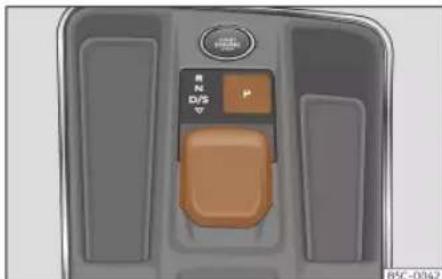
Fig. 145 In the centre console: selector lever.
The selector lever position is shown when the corresponding sign lights up. The engaged gear is also displayed on the screen in manual shift positions M, D, S and E (when the ECO engine setting is selected in the Individual profile»» page 226).
In certain versions, S+ or M+ is also displayed on the screen when the Drift or CUPRA profile is selected >> page 226. S+ and M+ are more extreme shift modes than the conventional Sport (S) mode.
P - Parking lock
When the P button is pressed, the drive wheels are locked. Only press P when the vehicle is stationary >>> △.
To press the P button you must press the brake pedal simultaneously.
R - Reverse gear
Reverse gear must be engaged only when the vehicle is stationary and the engine is idling >> △
To engage reverse gear R, you must press the brake pedal simultaneously. The reverse lights switch on when the reverse gear R is selected and the ignition is on.
N - Neutral
In this position, the gear is in neutral.
Press the brake pedal to move the lever from N to D/S when the vehicle is stationary or at speeds below 3 km/h (2 mph) >> △.
D/S – Permanent forward drive position
The D/S position enables the gears to be operated in normal mode (D) or sport mode (S). To select Sport mode S, move the lever backwards. Pushing the lever again will select normal mode D. The selected driving mode is displayed on the instrument panel screen.
In normal mode (D), the gearbox selects the best gear ratio. This depends on the engine load, the road speed and the dynamic gear control programme (DCP).
Sport mode (S) should be selected for a sporty driving style. This setting makes use of the engine's maximum power output. When accelerating the gear shifts will be noticeable.
Under certain circumstances (e.g. on mountain roads) it can be advantageous to switch tiptronic mode»» page 220, to adapt the gears to suit the road conditions.
WARNING
• Take care not to press the accelerator pedal when the vehicle is stopped. The vehicle could start moving immediately (in some cases even if the parking brake is engaged) resulting in the risk of an accident.
- Never move the lever to R position when driving. Failure to follow this instruction could result in an accident or failure.
- With lever in any position, the foot brake must be depressed whenever the engine is running. This is because an automatic gearbox still transmits power even at idling speed.
- While you are selecting a gear and the vehicle is stopped with the engine running, do not accelerate. Failure to follow this instruction could result in an accident.
- As a driver you should never leave your vehicle if the engine is running and a gear is engaged. Switch on the electronic parking brake and select the parking lock (P).
Note
- If the lever is moved accidentally to N when driving, release the accelerator and let the engine speed drop to idling before selecting gear range D or S again.
Driving
- If the power supply is interrupted while the P parking lock is active, it will not be possible to move the lever. If this should happen the manual release can be used. In this case, you should seek professional assistance.
Note
- If a gear has been selected, the vehicle does not move forwards or back. Proceed to the next mode:
- When the vehicle does not move in the required direction, the system may not have the gear range correctly engaged. Press the brake pedal and engage the gear range again.
- If the vehicle still does not move in the required direction, there is a system malfunction. Seek specialist assistance and have the system checked.
Changing gear in Tiptronic mode

Fig. 146 Steering wheel: automatic transmission levers
Tiptronic gives the driver the option to change gears manually.
When you change to the Tiptronic programme, the vehicle remains in the currently selected gear. This is possible as long as the system is not changing gear automatically due to a traffic situation.
Using Tiptronic with the steering wheel paddles
The gear shift paddles can be used when the selector lever is in the D/S position.
- Press the gearshift paddle + to select a higher gear>> Fig. 146.
- Press the gearshift paddle ⏻ to select a lower gear.
• To exit the Tiptronic mode, pull the right-hand gear shirt paddle towards the steering wheel for approximately 1 second.
To keep Tiptronic mode permanently switched on, move the selector lever to the S position. If the selector lever is in position D and the gear shift paddles are not operated for some time, the Tiptronic mode will automatically be switched off.
CAUTION
- When accelerating, if a higher gear is not selected, it will automatically change shortly before reaching the maximum permitted RPM.
- Also, if a lower gear is selected, the system will not change until it detects that the engine will not reach its maximum RPM.
Driving with an automatic gear-box
The gearbox changes gear ratios automatically as the vehicle moves.
The engine can only be started with the lever in the N position and the P button must be lit up (the parking lock remains active).
Driving down hills
Under certain circumstances it may be advantageous to use the Tiptronic mode to
Start and driving
select the gear manually according to driving conditions >>> ▲.
Stop/Park
To park on flat ground, just press the P button >> Fig. 145. On slopes the parking brake should first be applied and then press the P button.
If the driver door is opened and the P button has not been activated, the vehicle could move. The following warning is displayed on the instrument panel: Ⓧ Gear change: selector lever in the drive position!. Additionally, a buzzer will sound.
Stopping on a downhill
Always apply the brake pedal firmly to prevent the vehicle from moving; if necessary, apply the electronic parking brake»
Do not accelerate while a range of gears is engaged to prevent the car from rolling downhill >>>①.
Starting off uphill with the Auto Hold function
- Once you have engaged a gear, take your foot off the brake pedal and gently press the accelerator.
Starting off uphill without the Auto Hold function
- Pull on the electronic parking brake button.
- Once you have engaged a gear, gently press the accelerator and pull on the electronic parking brake button.
Back-up programme
If all the positions of the lever are shown over a light background on the instrument cluster, there is a system fault and the automatic gearbox will operate with the backup programme. It is still possible to drive the vehicle, however, at low speeds and within a selected range of gears. Driving in reverse gear may not be possible.
Parking lock manual release mechanism
If, in the event of a power failure (e.g. the 12-volt vehicle battery is drained), the vehicle must be towed and the parking lock can be released manually. In this case, you should seek professional assistance.
Kick-down
The kick-down device provides maximum acceleration when the gear selector lever is in the positions D, S or in Tiptronic mode.
When the accelerator pedal is pressed right down, the automatic gearbox will shift down to a lower gear, depending on road speed
and engine speed. This takes advantage of the maximum acceleration of the vehicle >>> △
The upshift to the next higher gear is delayed until the engine reaches maximum rpm.
WARNING
Observe the safety warnings»» in Selector lever positions on page 219.
- Never allow the brake to rub and do not use the brake pedal too often or for long periods, as the brakes can overheat. This reduces the braking power, increases the braking distance or even causes a brake system fault.
- If you have to stop on a hill, keep the vehicle's brakes applied with the brake pedal or parking brake.
WARNING
Please note that if the road surface is slippery or wet, the kick-down feature could cause the driving wheels to spin, which could result in skidding.
CAUTION
- If you stop the vehicle on a gradient, do not attempt to stop it from rolling by depressing the accelerator when a gear has been selected. This could cause overheating and damage the automatic gearbox.
Driving
- If you allow the vehicle to roll with the lever in position N and the engine off, the automatic gearbox will be damaged due to a lack of lubrication.
- In certain driving situations or traffic conditions, the gears could overheat and be damaged! If the warning lamp ⏻ lights up, stop the vehicle as soon as you can and wait for the gearbox to cool»» page 223.
- If the gearbox operates with the backup programme, take the vehicle to a specialised workshop and have the fault repaired without delay.
Launch-control program
The Launch-control programme enables maximum acceleration from a standstill.
Condition: the engine must have reached operating temperature and the steering wheel must not be turned.
The engine speed for Launch-control is different on petrol and diesel engines.
To use the Launch-control you must disconnect the traction control (TCS) or activate the ESC Sport or ESC OFF mode, using the Infotainment system menu: press the function button > Assistants > ESC Menu. The warning lamp will remain on.
- Press the brake pedal with your left foot and hold it down for at least one second.
- Set the selector lever to position S or Tiptronic, or select the Sport or Cupra Drive Profile» page 226.
- With your right foot, press the accelerator down to the full throttle or kick-down position. The engine speed will stabilise at about 3,200 rpm (petrol engine) or about 2,000 rpm (diesel engine).
• Take your left foot off the brake pedal. The vehicle starts with maximum acceleration.
WARNING
• Always adapt your driving style to the traffic conditions.
- Only use the Launch control programme when road and traffic conditions permit, and make sure your manner of driving and accelerating the vehicle does not inconvenience or endanger other road users.
- Make sure that the ESC remains switched on. Please note that when the TCS and ESC are deactivated, the wheels may start to spin, causing the vehicle to lose grip. Risk of accident!
- After moving off, you should activate the TCS or deactivate the ESC "sport" mode again using the Infotainment system: function button > Assistants.
Note
• After using the Launch control programme, the temperature in the gearbox may have increased considerably. In this case, the programme could be disabled for several minutes. The programme can be used again after the cooling phase.
- Accelerating with the launch control programme places a heavy load on all parts of the vehicle. This can result in increased wear and tear.
downhill assistant
Downhill speed control is activated when the lever is in the D/S position and the brake is applied. An appropriate lower gear is engaged.
The assistant attempts to maintain the speed at which the vehicle was travelling when the brake was applied, within logical limits. It may be necessary to correct the speed by pressing the brake.
The assistant can only change down as far as 3rd gear. It is possible that on very steep slopes you may have to switch to tiptronic mode and thus manually change down to 2nd or 1st gear to take advantage of engine braking and take the load off the brake system.
Start and driving
Downhill speed control is deactivated as soon as the road levels out again or you press the accelerator pedal.
On vehicles with a cruise control system >> page 236, downhill speed control is activated when you set a cruising speed.

WARNING
The downhill speed control cannot defy the laws of physics. Therefore, speed cannot be maintained constant in all situations. Always be prepared to use the brakes!
Hill Hold Control (HHC)
When driving up a slope or driving in Off-road with the lever in position D/S, stopping the vehicle switches on the hill hold control.
When the brake pedal is released, the assistant keeps the vehicle's brakes applied for a few seconds to give the driver time to press the accelerator pedal and continue driving.
Inertia mode
The inertia mode allows you to travel certain distances without using the accelerator, which saves fuel. Plan ahead and use the inertia mode to "let" the vehicle "roll".
Activation of the inertia mode
Condition: lever in position D, slopes of less than 12% and speeds between 20 and 130 km/h (12 and 80 mph).
• Gently take your foot off the accelerator.
The indication will be shown on the instrument panel©, the engaged gear and current consumption will disappear and the word Inertia will appear.
The gears will automatically disengage and the vehicle will roll freely, without the effect of the engine brake. While the vehicle rolls, the engine runs at idling speed.
Stopping inertia mode
- Press the brake or the accelerator pedal.
To take advantage of the engine's inertia mode, simply remove your foot from the accelerator.
Applying both the inertia mode (= prolonged section with less energy) and inertia disconnection (= shorter section without the need for fuel) facilitates improved fuel consumption and emission balance.
With Drive Profile>> page 226, the inertia mode can be activated in the Comfort or Individual profiles. If the engine is set to Eco in the Individual profile, it activates when the operating conditions are met, regardless of how smoothly you remove your foot from the accelerator.

WARNING
- If the inertia mode has been switched on, take into account, when approaching an obstacle, that the vehicle will not decelerate in the usual manner: risk of accident!
- When using inertia mode while travelling down hills, the vehicle can increase speed: risk of accident!
- If other users drive your vehicle, warn them about inertia mode.

Note
- The operation of the inertia mode in combination with hybrid engines (MHEV and PHEV) can cause the combustion engine to switch off.
- The inertia mode will be automatically disconnected on gradients steeper than 15% .
Indications on the instrument panel display
Clutch
Clutch overheating! Please stop!
- The clutch has overheated and could be damaged. Stop and wait for the gearbox to cool with the engine idling and press the P
»
Driving
parking lock button. When the warning lamp and the driver message turn off, go to a specialised workshop to get the fault repaired. If they do not turn off, do not continue driving. Seek specialist assistance.
Faults in the gearbox
Gearbox: Fault! Stop the vehicle and place the lever in the position P.
- There is a fault in the gearbox. Stop the vehicle in a safe place and do not continue driving. Seek specialist assistance.
Gearbox: System fault! You may continue driving.
- Have the fault corrected by a specialised workshop without delay.
Gearbox: System fault! You can continue driving with restrictions. Reverse gear disabled
• Take the vehicle to a specialised workshop and have the fault repaired.
Gearbox: System fault! You can continue driving in D until switching off the engine
- Park the vehicle in a safe place. Seek specialist assistance.
Gearbox: too hot. Adapt your driving accordingly
- Continue driving at moderate speeds. When the warning lamp switches off, you can continue driving in a normal manner.
Gearbox: press the brake and engage a gear again.
- If the warning was caused by the temperature of the gearbox, this driver message will be displayed when the gearbox has cooled again.
Gear-change recommendation
Selecting the optimal gear
Depending on the equipment on the instrument panel screen, a recommendation is shown with the gear that should be engaged to optimise consumption.
Displayed only when driving in Tiptronic mode>>>page 220.
No recommendation will appear if the optimal gear is engaged. The current gear will be displayed.
Display Meaning
| 3 | Optimum gear. |
| 4▶5 | Changing to a higher gear is recommended. |
| 1◀2 | Changing to a lower gear is recommended. |
Information regarding the "cleanliness" of the particulate filter
When the exhaust system detects that the particulate filter is close to saturation, this system's self-cleaning function recommends the optimal gear for that function >> page 321.
WARNING
The gear change recommendation is an auxiliary function and in no case should be a substitute for careful driving.
- Responsibility for selecting the correct gear, depending on the circumstances, rests solely with the driver.
For the sake of the environment
Selecting the correct gear can help to save fuel.
Note
The recommended gear display turns off when you are no longer in tiptronic mode.
Start and driving
Hill Descent Control (HDC)
Control lamps

It lights up white
Hill Descent Control is active.

It lights up grey
Hill Descent Control is not active. The system is switched on, but is not adjusting.
Some control and warning lamps will light up briefly when the ignition is switched on to check certain functions. They will switch off after a few seconds.

WARNING
Observe the safety warnings>>> in Control and warning lamps on page 84.
Description and operation
Hill Descent Control limits the speed on steep descents by automatically braking all four wheels, both when moving forward and in reverse. As the anti-lock brake system remains active, it prevents the wheels from locking.
After starting the descent of a slope below 30 km/h (18 mph), speed is limited to a mini-
mum of 2 km/h (1 mph) and a maximum of 30 km/h (18 mph). When appropriate, the driver may increase or decrease the speed within the limit by pressing the accelerator or the brake. At this point the function is interrupted and, if necessary, it is then reactivated.
Even so, it is imperative that the surface guarantees sufficient adhesion. For this reason, the Hill Descent Control will not fulfil its function when, for example, descending a slope with a frozen or slippery surface.
Hill Descent Control is available when the dash panel display shows the message 🔊.
Hill Descent Control automatically intervenes if the following conditions are met:
• The vehicle engine is running.
- The Offroad driving profile has been selected»» page 226. Driving at a speed below 30km / h (18 mph) (the message 🔗 is shown on the instrument panel).
- The slope of the descent is at least 10% when driving forward and 9% when driving in reverse.
- The brake and the accelerator are not pressed.
Hill Descent Control is deactivated on pressing the brake and the accelerator or if the slope is below 5%. The function can be
switched off manually in the infotainment system using the 📄 > HDC function button.

WARNING
Always be ready to brake. Otherwise, an accident could occur and cause injury.
- Hill Descent Control is only an auxiliary system that in some situations may not sufficiently brake the vehicle when going down a slope.
• The speed of the vehicle may increase despite the intervention of Hill Descent Control.
Steering
Information relating to different vehicle processes.
Electro-mechanical power steering adapts electronically to the speed of the car, torque and steering angle.
Even if the power steering fails or the engine is stopped, it is possible to continue to rotate the steering wheel as long as the key remains in the ignition, but more force must be applied.
》
Driving
Progressive steering
Depending on the vehicle's features, it may or may not incorporate a progressive steering system.
In city traffic you do not need to turn so much on parking, manoeuvring or in very tight turns.
On the road or on the motorway, progressive steering transmits, for example, in bends, a sportier, more direct and noticeably more dynamic driving sensation.
Control lamp
It lights up red
Faulty steering.
Do not continue driving, stop the vehicle as soon as possible and in a safe manner. Take the vehicle to a specialised workshop and have the fault repaired as soon as possible.
@! It lights up yellow
Limited steering operation.
Drive carefully to a specialised workshop to have the steering checked.
If the warning light does not come on again after restarting the engine and driving a short distance, it is not necessary to check the steering.
OR: The 12-volt battery was disconnected and reconnected.
Drive a short distance at 15-20 km / h (9-12 mph).
It flashes yellow
The steering column is jammed.
When stopped, turn the steering wheel in both directions.
OR: The steering column does not unlock or lock. Turn off the ignition and turn it on again. Consider the messages shown on the instrument panel display.
Do not continue driving if the steering column remains locked after switching on the ignition. Seek specialist assistance.
The control lamp should light up for a few seconds when the ignition is switched on. It should go out once the engine is started.
WARNING
Never ignore the warning lamps or messages.
- If the warning lamps and the corresponding messages are ignored, the vehicle may stall in traffic, causing serious damage or accidents and injuries.
- Stop the vehicle at the next opportunity and in a safe place.
Driving modes (Drive Profile)
Introduction
The Drive Profile enables the driver to choose between the Comfort, Sport, Cupra and Individual, profiles, which modify the behaviour of several vehicle functions, providing different driving experiences.
In addition, the 4Drive version features the Offroad 1) and Snow profiles.
The Individual profile can be configured according to personal preferences.
The VZ5 version exclusively features the Drift profile.
Start and driving
Description
Depending on the equipment fitted in the vehicle, the Drive Profile can operate on the following functions:
Engine
Depending on the profile selected, the engine responds more quickly or smoothly to the accelerator being pressed.
In vehicles with automatic transmission, the behaviour of the transmission is modified, whenever a gear is changed up and down, and at other times. The idle level may also change according to the selected profile and selector lever position.
The Inertia Mode function can also be switched on by selecting the Comfort profile, or from the Individual profile by putting the engine into ECO mode. This allows fuel consumption to be reduced. Other factors can cause it to switch on»» page 223.
With manual transmission, the ECO profile changes the gear change recommendations to facilitate more efficient driving.
Engine sound
Depending on the equipment and the selected profile, it modifies the acoustic sensation in the vehicle's interior and the outside sound levels. It acts on several components of the vehicle to strengthen or weaken the
engine and intake noise, as well as the noise from the exhaust system. The configuration is preset for each profile and can be modified in the Individual profile.
Adaptive chassis control (DCC)
The DCC continuously adapts the damping of the suspension system to the characteristics of the road surface and the driving situation (speed, acceleration and steering wheel angle) according to the selected driving profile. The vehicle's dynamic behaviour is also adapted to improve grip on curves and turning capacity. Within the Individual profile you can also adjust the DCC level in a customised manner.
In the event of a fault in the DCC, the following message is displayed on the instrument screenFault: shock absorber regulation
Four-wheel drive (4Drive)
Modify the transmission to adjust the vehicle's traction capacity to the road surface. The acceleration capacity from a standstill will also be modified.
Steering
The power steering varies its driving modes and adapts to the profile selected, thus offering the best behaviour for each situation.
Air conditioning
Climatronic can operate in Eco mode, especially restricting fuel consumption.
Adaptive Cruise Control (ACC)
Depending on the driving profile, the performance of the ACC varies, to allow more sporty acceleration and braking or a more respectful fuel consumption.
PreCrash system
The PreCrash system adapts according to the selected configuration. The Sport and Offroad driving profiles have specific settings to adapt them to driving and terrain characteristics» page 22.
Hill descent control assistant
This assistant can be activated or deactivated in the Offroad profile. Hill Descent Control limits the speed on steep descents by automatically braking all four wheels, both when moving forward and in reverse >> page 225.
Hill Start Assist
It is possible to activate or deactivate this assistant in the Offroad profile» page 223.
》
Driving
Torque splitter (only the VZ5 version)
This distributes torque as appropriate between the rear wheels, giving more traction on corners.
Setting the driving profile
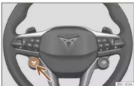
Fig. 147 Multifunction steering wheel: button to change the driving profile.
There are several ways to select a driving profile using the Infotainment System:
- Press the function button > Drive Profile, available profiles will be displayed.
- OR: Press the function button ⏻ > Vehicle settings > Drive Profile, available profiles will be displayed.
- OR: Press the function button Ⓞ, slide your finger horizontally across the screen to Drive Profile. Press on > to change the driving pro-
file or double press on the icon to show the available profiles.
- OR: With the Infotainment System turned off, by pressing on the Drive Profile icon, the available driving profiles will be displayed.
- OR: briefly press the CUPRA button on the left hand side of the steering wheel
Fig. 147 to change the driving profile. Press and hold the CUPRA button to access the Cupra profile directly.
The icon of the selected profile is displayed at all times in the upper central part of the instrument panel and on the Infotainment System screen when it is turned off » page 85.
Driving pro-
file
Characteristics
| Comfort | It permits more relaxed and comfortable driving, for example for long motorway journeys. Its main characteristic is the soft suspension setting (DCC). |
| Sport | It represents the vehicle's default behaviour, suitable for dynamic driving. |
| Cupra a) | It gives the vehicle a decidedly sportier nature, and makes for maximum performance. |
Driving pro-
file
Characteristics
| Individual | It allows you to personalise the configuration. The functions that can be adjusted depend on the equipment fitted in the vehicle. |
| Offroadb) | Maintains optimal off-road driving by allowing the personalisation of the vehicle's configuration parameters. |
| Drifti | Configures the vehicle to enable a controlled oversteer experience. |
a) Available in the VZ version.
b) Only for 4Drive models.
c) Only available in the VZ5 version.
WARNING
When operating the Drive Profile, pay attention to all traffic: doing otherwise could cause an accident.
Note
- When the engine is switched off it will store the driving profile that was selected when the ignition was turned off. When restarting, the engine and the gearbox will start in their Comfort mode. To return the engine and gear to your desired mode, re-select the corresponding driving profile.
Start and driving
- In the VZ5 version, when you switch the ignition off and on again, the Comfort driving profile is activated by default.
- When the vehicle is restarted after using the Offroad profile, the system is always activated in the Comfort profile.
- Your speed and driving style must always be adjusted to visibility, weather, and traffic conditions.
Driving tips
Running in
Please observe the instructions for running-in new components.
Running-in the engine
A new engine must be driven through a run-in period during its first 1500 kilometres (1000 miles). During its first few hours of running, the internal friction in the engine is greater than later on when all the moving parts have bedded down.
How the vehicle is driven for the first 1500 km (1000 miles) influences the future engine performance. Throughout the life of the vehicle, it should be driven at a moderate speed (especially when the engine is cold) this will reduce engine wear and increase its useful life. Never drive at extremely low en-
gine speeds. Always engage a lower gear when the engine works "irregularly". For the first 1000 km or 600 miles, please note:
- Do not use full throttle.
- Do not force the engine above two thirds of its maximum speed.
- Do not tow a trailer.
Between 1000 and 1500 kilometres (600 to 1000 miles), gradually increase power until reaching the maximum speed and high engine speeds.
Running in new tyres and brake pads
- Replacement of wheel rims and new tyres >> page 340.
• Information about brakes»» page 264.
For the sake of the environment
If the engine is run in gently, the life of the engine will be increased and the engine oil consumption reduced.
Four-wheel drive (4Drive)
On four-wheel drive models, the engine power is distributed to all four wheels
General notes
On four-wheel drive vehicles, the engine power is distributed to all four wheels. The distribution of power is controlled automatically according to your driving style and the road conditions. Also see» page 269.
The four-wheel drive is specially designed to complement the superior engine power. This combination gives the vehicle exceptional handling and performance capabilities, both on normal roads and in more difficult conditions, such as snow and ice. Even so (or perhaps especially for this reason), it is important to observe certain safety points >>> △
Winter tyres
Thanks to four-wheel drive, your vehicle will have plenty of traction in winter conditions, even with the standard tyres. Nevertheless, we still recommend that winter tyres or all-season tyres be fitted on all four wheels to give even better braking response.
Snow chains
On roads where snow chains are mandatory, this also applies to cars with four-wheel drive >> page 345.
Changing tyres
On vehicles with four-wheel drive, all four tyres must have the same rolling »
Driving
circumference. Also avoid using tyres with varying tread depths>>>page 340.
Off-roader?
Your CUPRA vehicle is not an off-roader: it does not have enough ground clearance to be used as such. It is therefore best to avoid rough tracks and uneven terrain as much as possible.
WARNING
• Even with four-wheel drive, you should always adjust your speed to suit the conditions. Do not let the extra safety features tempt you into taking any risks when driving. Risk of accident!
- The braking capability of your vehicle is limited by the tyres' grip. It is therefore no different from a car without four-wheel drive. So do not be tempted to drive too fast on firm or slippery roads just because the vehicle still has good acceleration in these conditions. Risk of accident!
- On wet roads bear in mind that the front wheels may start to "aquaplane" and lose contact with the road if the car is driven too fast. If this should happen, there will be no sudden increase in engine speed to warn the driver, as occurs with a front-wheel drive car. For this reason you should always choose a driving speed suitable for the road conditions. Risk of accident!
Economical and environmentally friendly driving
Fuel consumption, environmental pollution and wear to the engine, brakes and tyres all depend largely on driving style. Consumption can be reduced between 10-15% with an efficient driving type. The following section gives you some tips on lessening the impact on the environment and reducing your operating costs at the same time.
Active cylinder management (ACT®)
Depending on vehicle equipment, the active cylinder management (ACT®) may deactivate some of the engine cylinders if the driving situation does not require too much power. The number of active cylinders can be seen on the instrument panel display. >> page 67.
Foresight when driving
If you think ahead when driving, you will need to brake less and thus accelerate less. Take advantage of the inertia of the vehicle whenever possible, with a gear engaged. This takes advantage of the engine braking effect, reducing wear on the brakes and tyres. Emissions and fuel consumption will drop to zero.
Changing gear to save energy
An effective way of saving is to change in advance to a higher gear.
Manual gearbox: change from first to second gear as soon as possible. Choosing the correct gear saves fuel. Select the highest possible gear suitable for the driving situation (the engine should continue to run with cyclical regularity).
Automatic transmission: accelerate gradually and without reaching the "kick-down" position.
Avoid driving at high speed
Avoid travelling at your vehicle's top speed, whenever possible. Fuel consumption, emission of harmful gases and noise pollution multiply as speed is increased. Driving at moderate speeds will help to save fuel.
Reduce idling time
In vehicles with the Start-Stop system idling is automatically reduced. In vehicles without the Start-Stop system it is worth switching off the engine, for example, at level crossings and at traffic lights that remain red for long periods of time. When an engine has reached operating temperature, and depending on the cylinder capacity, keeping it switched off for a minimum of about 5 seconds already saves more than the amount of fuel necessary for restarting.
Start and driving
The engine takes a long time to warm up when it is idling. Mechanical wear and pollutant emissions are also especially high during this initial warm-up phase. It is therefore best to drive off immediately after starting the engine. Avoid running the engine at high speed.
Regular maintenance
Regular servicing helps in saving fuel even before the engine is started. A well-serviced engine gives you the benefit of improved fuel efficiency as well as maximum reliability and an enhanced resale value. A badly serviced engine can consume up to 10% more fuel than necessary.
Avoid short journeys
The engine and catalytic converter need to reach their optimal operating temperature in order to minimise fuel consumption and emissions.
A cold engine consumes a disproportionate amount of fuel. The engine reaches its working temperature after about four kilometres (2.5 miles), when fuel consumption will return to a normal level.
Check tyre pressure
Always make sure the tyres are inflated to the correct pressures»» page 342 to save fuel. If the pressure is below half bar, fuel consumption may increase by 5%. Due to the greater rolling resistance, under-inflation also increases tyre wear and impairs handling.
Do not use winter tyres all year round as they increase fuel consumption by up to 10%.
Avoid carrying unnecessary loads
Given that every kilo of extra weight will increase the fuel consumption, it is advisable make sure that no unnecessary loads are being transported.
Since the luggage rack increases the aerodynamic drag of the vehicle, you should remove it when not needed. At speeds of 100-120 km/h (62-75 mph), this will save 12% of fuel.
Save electrical energy
The engine drives the alternator, thereby generating electricity. This implies that any increase in power consumption also increases fuel consumption! For this reason, switch off any unneeded electrical devices. Devices that use a lot of electricity include the blower at a high setting, the rear window heating or the seat heating.
Plug-in hybrid drive: brake early and evenly to take advantage of energy recovery.
Note
- If you have the Start-Stop system, it is recommended that it should not be disconnected.
- It is recommended that you close the windows when driving at more than 60 km/h (37 mph).
- Do not drive with your foot resting on the clutch pedal, as the pressure can make the plate slip. This causes wear and can damage the clutch plate.
- Do not ride the clutch on a hill, use the brake. The fuel consumption will be lower and you will prevent the clutch plate from being damaged.
- Use the engine brake on downhills by changing to the gear that is best suited for the gradient. Fuel consumption will be "zero" and the brakes will not suffer.
Driving on flooded roads
To prevent damage to the vehicle driving on flooded roads, take the following into account:
- The water should never come above the lower edge of the bodywork.
- Drive at pedestrian speed.
Driving

WARNING
After driving through flooded zones, braking effectiveness can decrease if the brake discs or pads are damp»» page 264.

CAUTION
- Driving through flooded areas may damage vehicle components such as the engine, transmission or electrical system.
- Whenever driving through water, the Start-Stop system must be switched off >> page 214.

Note
- Check the depth of the water before entering the flooded zone.
- Do not stop in the water, drive in reverse, or stop the engine.
- Vehicles travelling in the opposite direction cause waves that could exceed your vehicle's critical height.
- Avoid driving through salt water (corrosion) >> page 353.
Trips abroad
- With petrol vehicles, it should be ensured that lead-free petrol is available throughout the journey» page 317, Fuel types. Seek
information about service station networks selling unleaded fuel.
- In some countries, it is possible that your vehicle is not sold and some spare parts may not be available or the technical services may only be able to make limited repairs.
CUPRA distributors and importers will provide information about the technical preparation that your vehicle requires and also about necessary maintenance and repair possibilities.

CAUTION
CUPRA does not accept liability for any damage to the vehicle due to the use of a lower quality fuel, an inadequate service or the non-availability of genuine spare parts.
Driver assistance sys- tems
General notes
Safety advice

WARNING
- Responsibility for driving rests with the driver at all times. The driver assistance systems are not a replacement for driver attention. Focus all your attention on driving and be prepared to intervene at all times.
- Use the driver assistance systems only when conditions allow. The driving style must always be suitable for the weather, visibility, road and traffic conditions.
- In order for driver assistance systems to react correctly, sensors and cameras must operate without limitations. Please read the notes on sensors and cameras in this chapter.

Note
- Keep in mind the specific rules of each country, especially when it comes to driving, formation of an emergency corridor, braking distance, speed, parking position,
Driver assistance systems
wheel position, etc. The driver is solely responsible for always complying with the specific regulations of each country.
- The area in front of and around the radar sensor should not be covered with adhesives, additional headlights or similar items, as this could have a negative impact on the operation of the assistants. If the vehicle is not properly repaired or structural modifications are made to it, the operation of the assistants may be affected.
- The repair and adjustment of sensors and cameras requires special knowledge and tools. It is recommended to visit a CUPRA dealership for this purpose.
System limits
WARNING
- Driver assistance systems can not overcome the laws of physics. Depending on the circumstances, a collision may not be avoidable.
- Warnings, notices and indicator lamps may not be displayed on time, or may be displayed incorrectly, e.g. if a vehicle approaches too quickly.
- Corrective interventions by driver assistance systems (e.g. interventions in the steering or brakes) may be insufficient or may never occur, depending on the cir-
cumstances. As a driver, you must be prepared to act at all times.
Note
- Due to the system's detection limits in the surroundings, the systems may not give warnings or intervene on time, or they might do so even if it is not desired. In addition, the auxiliary systems may incorrectly interpret a manoeuvre and, as a result, warn the driver in an unexpected manner.
- When the towing mode is selected, some assist systems may react with limitations, in an unusual way or may not be available. Keep in mind the instructions relating to the towing mode.
Driver assist and cameras
Front radar

Fig. 148 On the front bumper: rarsors.

Fig. 149 Detection area.
A radar sensor may be fitted to the bumper of the vehicle»» Fig. 148 . radar detects any objects in its det
Driving
zone >>Fig. 149 and provides support for the following functions:
- Front Assist»» page 240.
- Adaptive Cruise Control (ACC) >> page 244.
The radar can have a range of up to 120m (400ft) depending on road and weather conditions.
WARNING
The visibility of the radar sensor can be impaired by dirt or environmental influences such as rain, fog, snow, mud, dust, insects etc. In this case the Front Assist and ACC functions may stop working. The instrument panel displays the following message: No sensor vision! And the Front Assist unavailable or ACC unavailable warning lights come on.
- Clean the sensor area on the bumper as indicated in >> page 355, Cleaning the exterior. When the radar sensor starts correctly detecting again, the message disappears from the screen and the functions become available again.
CAUTION
- If the radar sensor is dirty or poorly adjusted, the Front Assist system may give unnecessary warnings and apply the brakes inappropriately.
- The operation of the radar can be affected by strong reflections of the emitted signal. This may occur, for example, in an enclosed car park or due to the presence of metallic objects (e.g. guard rails or sheets used in road works).
- The sensor may not be adjusted correctly if it receives an impact. This may compromise the system's efficacy or disconnect it. If you have the feeling that the radar sensor is damaged or adjusted incorrectly, switch off the Front Assist and ACC functions to avoid any damage. If this occurs have it adjusted.
Front camera

Fig. 150 On the windscreen: field of vision of the Lane Assist system.
Depending on the equipment, the vehicle may be fitted with a front camera on the front windscreen»»Fig. 150 . This camera
detects lane boundaries (lines) to provide support for the following functions:
• Lane Assist»» page 252.
• Travel Assist» page 254.
• Emergency assist»» page 256.
CAUTION
To avoid affecting the operation of the systems, take the following points into consideration:
- Clean the field of vision of the camera regularly and make sure it is free of snow and ice.
- Do not cover the field of vision of the camera.
- Check that the windscreen is not damaged in the area of the camera's field of vision.
Driver assistance systems
Rear radar

Fig. 151 Rear view of the vehicle: radar sensor zones.

Fig. 152 Sensor detection zones
The radar sensors are located on the left and right of the bumper and are not visible from the outside >> Fig. 151. The sensors monitor both the blind spot and traffic behind the vehicle >> Fig. 152.
They support the following functions:
- Lane departure warning (Side Assist) >> page 259.
- Rear cross traffic alert (RCTA)>>>page 261.
- Door opening warning (Exit Assist) >> page 262.
Automatic deactivation of supported functions
The rear radar sensors deactivate automatically when, among other reasons, one of the sensors is detected to be permanently covered. This may be the case if, for example, there is a layer of snow or ice over one of the sensors.
The relevant text message will appear in the dash panel display.
CAUTION
• The radar sensors on the rear bumper may be damaged or shifted in the event of a collision, for example, when entering or exiting a parking space. This may result in the system disconnecting itself, or at least possibly having its functionality diminished.
• In order to ensure that the radar sensors work properly, keep the rear bumper free of snow and ice and do not cover it.
- The rear bumper should only be painted with paint authorised by CUPRA. The lane departure warning's functions may be limited or work incorrectly if other paints are used.
- The visibility of radar sensors may be affected due to leaves, snow, strong haze or dirt, among others. Clean the area in front of the sensors.
- Never use the lane departure warning, the rear cross traffic alert or the door opening warning if the radar sensors are dirty.
Ultrasound sensors
The bumpers are fitted with ultrasound sensors to perform the following functions:
• Park Assist» page 274.
- Parking aid Plus»» page 282.
• Rear parking aid» page 285.
CAUTION
- Damage to the radiator grille, bumper, wheel arch and vehicle underbody can modify the orientation of the sensors. This can affect the parking aid function. Have the function checked by a specialised workshop.
- A number plate or number plate holder with dimensions that exceed the space for the number plate, or a cured or deformed number plate can cause false detections or a loss of visibility for the sensors.
Driving

Note
• In order to guarantee good operation, keep the sensors clean, free of snow and ice, and do not cover them with stickers or other objects.
- If you use high-pressure or vapour equipment for cleaning, do not apply it directly, unless you do so very briefly, and always keep a distance of more than 10 cm away.
- Fitting certain accessories to the front of the vehicle, such as a plate holder with advertising, may interfere with the operation of the Park Assist.
Area View system

Fig. 153 In the rear lid handle: location of the reverse assist camera.
Depending on your vehicle's equipment, it can be fitted with 1 or 4 cameras that provide support to the following functions:
• Area View>> page 286
• Rear View Camera»» page 288.

WARNING
The use of a number plate may interfere in the views shown on the screen, since the cameras' field of vision may be reduced.

CAUTION
- In order to guarantee good system operation, keep the cameras clean, free of snow or ice, and do not cover them with adhesives or other objects. The camera can be cleaned by operating the windscreen wiper.
- The vehicle is fitted with a cleaning system for the rear camera. To operate it, push the wiper lever away from the steering wheel (the camera will be cleaned at the same time as the rear window). If the camera is still dirty after using it, clean it manually.
- Never use abrasive cleaning products to clean the camera lenses.
- Do not use hot or warm water to remove ice or snow from the camera lenses. Doing so could damage the lenses.
Cruise control system (CCS)
Introduction
The cruise control system (GRA) helps maintain a constant speed set by you.
Speed range
The cruise control system is available when driving in forward gear at a speed of over approx. 20 km/h (15 mph).
Temporarily switching off the cruise control
The saved speed can be exceeded at any time, e.g. for overtaking. The cruise control is suspended during acceleration and is then resumed with the saved speed.
Status display
When the cruise control system is switched on, the instrument cluster display shows the saved speed and the system status:

It lights up grey
The cruise control system is switched on, but regulation is not active.

It lights up green
The cruise control system is switched on and regulation is active.
Driver assistance systems
If there is no speed saved, the instrument cluster display shows --- instead of speed.
Changing gears
As soon as the clutch pedal is depressed, regulation is suspended and resumes once the gear change has been made.
Driving down slopes
Shift into a low gear before descending a long hill. This makes use of engine braking and relieves the brakes.
Driving down slopes
Shift into a low gear before descending a long hill. This makes use of engine braking and relieves the brakes.

WARNING
If it is impossible to drive with sufficient braking distance and at a constant speed, using the cruise control system may cause accidents and serious injuries may occur.
- Do not use Travel Assist when visibility is bad, on steep roads, on windy roads or in slippery circumstances (such as snow, ice, rain or loose gravel), or on flooded roads.
- Only use the cruise control system on paved roads with a firm surface.
- Adapt your speed and safety distance to the vehicle in front of you at all times to suit
the visibility, weather, road and traffic conditions.
• After use, always switch off the speed limiter to prevent the speed being regulated against your wishes.
- It is dangerous to use a set speed which is too high for the prevailing road, traffic or weather conditions.
Operating the cruise control

Fig. 154 On the multifunction steering wheel: buttons to operate the speed limiter.
Connecting
- Press the 📄 button.
There is no speed saved and regulation is not yet operating.
Start regulation
- When the vehicle is moving, press the button SET.
The cruise control system saves and regulates the current speed.
Adjusting the speed
While the GRA is set, the stored speed can be adjusted:
RES + 1 km/h (1 mph)
SET - 1 km/h (1 mph)
-
- 10 km/h (5 mph)
- -10 km/h (5 mph)
The vehicle adapts the current speed by accelerating or stopping accelerating.
Interrupting the adjustment
- Briefly press the button ☑ on the multifunction steering wheel or press the brake pedal.
The speed is stored.
Reinstating the cruise control
- Press theRES button.
The cruise control system resumes the saved speed and regulates it.
Driving
Switching off
- Press and hold the button 📄.
The cruise control system switches off and the saved speed is deleted.
Switching off the speed limiter
- Press the Ⓗ button.
- Select the speed limiter on the instrument cluster display.
The cruise control system is switched off.
Problems and solutions

Temporarily switching off the cruise control
The control lamp switches on yellow.
- Abnormal operation. Switch off the cruise control system and take the vehicle to a specialist workshop.
The adjustment is interrupted unexpectedly
- If the clutch pedal is pressed for a long time.
- The vehicle has exceeded the saved speed for a long time.
- No forward gear has been selected.
- A brake assistance system has intervened, e.g. TCS or ESC.
• Front Assist has braked the vehicle. - If the fault continues, disconnect the Emergency Assist and consult a specialised workshop.
Speed limiter
Introduction
The speed limited helps the driver not to exceed a set speed.
Speed range
The speed limiter helps avoid exceeding a programmed speed, from 30 km/h (20 mph) approx. and faster.
By selecting the speed limiter
The speed limitation can be interrupted at any time by depressing the accelerator pedal fully, beyond the point of resistance. As soon as the saved speed is exceeded, the green indicator light flashes and an audible warning signal sounds. The speed is stored.
The limiter is reactivated automatically after returning to less than the set speed.
Status display
When the speed limiter is switched on, the instrument cluster display shows the saved speed and the system status:

It lights up grey
The speed limiter is switched on but regulation is not active.

It lights up green
The speed limiter is switched on and active.
Driving down slopes
Shift into a low gear before descending a long hill. This makes use of engine braking and relieves the brakes.

WARNING
After use, always switch off the speed limiter to prevent the speed being regulated against your wishes.
- The speed limiter does not relieve the driver of their responsibility to drive at the appropriate speed. Do not drive at high speed if not necessary.
- Using the speed limiter under adverse weather conditions is dangerous and can cause serious accidents, e.g. aquaplaning, snow, ice, leaves, etc. Only use the speed limiter when the status of the road and the weather conditions allow it.
Driver assistance systems
Operating the speed limiter
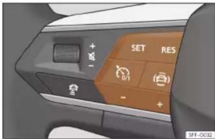
Fig. 155 On the multifunction steering wheel: buttons to operate the speed limiter.
Connecting
- Press the 📄 button.
It does not take effect yet.
Start regulation
- When the vehicle is moving, press the button SET.
The current speed is saved as a limit speed.
Adjusting the speed
The programmed speed can be set:
RES + 1 km/h (1 mph)
SET - 1 km/h (1 mph)
+ + 10 km/h (5 mph)
- -10 km/h (5 mph)
Interrupting the adjustment
- Press the 📄 button.
The speed is stored.
Reinstating the cruise control
- Press the RES button.
The limiter will re-activate as soon as the vehicle is moving at a speed lower than the saved one.
Switching off
- Press and hold the button 📄
The speed limiter switches off and the speed is deleted.
Switch to cruise control (GRA) or adaptive cruise control (ACC)
- Press the @ button.
- Observe the corresponding message on the instrument cluster display.
The speed limiter is switched off.
Problems and solutions
! LIM The speed limiter is not active.
The control lamp switches on yellow.
- Malfunctions Switch off the speed limiter and go to a specialist workshop.
The adjustment is interrupted unexpectedly
- You have switched off the Electronic Stabilization Control (ESC).
- The brakes have overheated. Wait for the brakes to cool down and check the operation again.
- If the fault continues, consult a specialised workshop.
For safety reasons, the speed limiter only switches off fully whenever the driver stops pressing the accelerator pedal or switches the system off manually.
Not possible to start regulation
- The selected driving profile does not allow regulation to start. Select another profile and repeat the procedure.
Driving
emergency brake assistance system (Front Assist)
Introduction
The objective of the system is to prevent head-on collisions against objects that may be in the vehicle's path or minimise the consequences of such impacts.
The function is designed to avoid collisions against:
- Parked vehicles.
• Vehicles, pedestrians and cyclists that are travelling in the same lane and direction. - Pedestrians and cyclists who transversely cross the vehicle path.
The Front Assist records the mentioned objects by means of a camera on the top of the windscreen and a radar sensor on the front of the vehicle» page 233.
Depending on several factors and how critical the situation is, the system operates in a staggered manner.
First informing the driver, and if there is no or insufficient reaction, then activating an autonomous emergency braking or an evasive manoeuvre as indicated by the conditions that will be discussed in the following points.
The system can be cancelled if the accelerator pedal is pressed or the steering wheel is turned firmly.
Depending on the equipment and the country, the Front Assist also includes the following functions:
- Pedestrian protection»» page 241
• Cyclist protection»» page 241
• Dodge assist»» page 241 - Turn assist»» page 242
WARNING
- Front Assist is a driving assistance function that can never replace the driver's attention.
- Front Assist cannot change the laws of physics or replace the driver in terms of keeping control of the vehicle and reacting to a possible emergency situation.
- Following a Front Assist emergency warning, pay immediate attention to the situation and try to avoid the collision where appropriate.
Warning levels and brake assist

Fig. 156 On the instrument panel display: advance warning indications.
Front Assist is active between 5 km/h (3 mph) and 250 km/h (155 mph). Depending on different conditions (vehicle speed, speed and type of object recognised, etc.), some of the stages described below are omitted to optimise the performance of the system.
Safety distance warning
If the system detects that you are driving too close to the vehicle in front, it will warn the driver with this indication on the instrument panel display ⏻!».
The timing of the warning varies depending on driver behaviour, vehicle speed and relative speed between both.
The safety distance warning is active between approx. 65 km/h (40 mph) and 250 km/h (155 mph).
Driver assistance systems
Advance warning
If the system detects a possible collision with the vehicle in front, it alerts the driver by means of an audible warning and an indication on the instrument panel display (5) >> Fig. 156.
The warning moment varies depending on the traffic situation and driver behaviour. At the same time, the vehicle will prepare for a possible emergency braking»» in Introduction on page 240.
When Front Assist is connected, the indications of other functions on the screen may be hidden.
Critical warning
If the driver fails to react to the advance warning, the system may actively intervene in the brakes and generate a brief jolt to warn the driver of the imminent danger of a collision.
Automatic braking
If the driver also fails to react to the critical warning, the system may initiate independent emergency braking by progressively increasing the braking in accordance with the criticality of the situation.
Driver emergency braking assistance system
If the driver, after the critical warning, starts braking but the system detects that the brake is not being applied with sufficient force, the braking intensity will be increased. This brake assist only occurs if the pedal is pressed firmly.
WARNING
- The system cannot prevent a collision, although it can significantly minimise the consequences by reducing the speed and the force of the impact.
- When the Front Assist causes a braking, the brake pedal is "harder".
• Automatic interventions by the Front Assist on the brakes may be interrupted by pressing the accelerator or moving the steering wheel. - The Front Assist may brake the vehicle until it stops completely. However, the brake system does not halt the vehicle permanently. Use the foot brake!
Pedestrian and cyclist recognition
The system recognises pedestrians and cyclists who travel in the same lane and direction and pedestrians and cyclists who transversely cross the vehicle's path.
Pedestrian and cyclist recognition technology cannot exceed the physically prescribed limits and works exclusively within the system's limits. The responsibility for braking always depends on the driver.
The pedestrian and cyclist recognition can cause undesired warnings and braking interventions, e.g. with a hidden radar sensor or a dirty camera field of vision.
Be ready to take charge of the vehicle at any time.
The pedestrian and cyclist recognition operating speed range is lower than that of the Front Assist.
Dodge assist
Dodge assist helps the driver avoid an obstacle in critical conditions.
Once the Front Assist has activated a critical warning, if the driver intends on dodging the object, the dodge assist will help correct the trajectory. The driver must start and finish the manoeuvre, as this is an assistance system and not an autonomous one.
Front Assist is active between approx. 30 km/h (20 mph) and 150 km/h (90 mph).
Driving
Limitations
This system does not react to objects that cross transversely or to animals. The basic limitations of the Front Assist must also be taken into account»»page 242.
Turn assist
Turn assist can avoid a collision with a vehicle approaching in the opposite direction, by braking the vehicle itself when the intention is to turn.
This system is active up to 15 km/h (9 mph).
Limitations
The turn-off assist function is available if you have indicated your intention to turn by activating the turn signal, you have turned the steering wheel and the turning path has started.
It only reacts to vehicles that are in the path of the vehicle (not to animals, people, etc.).
The basic limitations of the Front Assist must also be taken into account»» page 242.
System limitations

Fig. 157 On the instrument panel display: initial system self-calibration indication.
Front Assist has certain limitations inherent to the system. Thus, in certain circumstances, some of the reactions may be inappropriate from the driver's standpoint. So pay attention in order to intervene if necessary.
The following conditions may cause the Front Assist not to react or to do so too late:
- In the first few instants of driving after switching on the ignition, due to the system's initial auto-calibration. During this phase, the instrument panel screen will display the following indication»»Fig. 157.
Unrecognised objects
- Vehicles travelling outside the reach of the sensors at close range from your own vehicle.
• Vehicles that suddenly change to the lane on which your vehicle is travelling.
- Pedestrians that cannot be recognised because they are partially or totally hidden.
- Objects such as walls, posts, fences, trees or garage doors.
- Loads and accessories of other vehicles that protrude over the sides, backwards or over the top.
- Other vehicles crossing the vehicle's path.
• In the case of pedestrians or cyclists standing or approaching in the opposite direction.
Operating limitations:
In the following situations, the Front Assist may work late or in an undesirable manner. The following icon is displayed Ⓞ(in yellow) in the instrument panel, accompanied by the message Front Assist with limitations.
- If the Front Assist or the front camera are disabled or broken.
- If the radar sensor or the front camera are dirty or covered.
- On taking tight bends or complex paths.
- When pressing the accelerator firmly or at full throttle.
- If the TCS has been disconnected or the ESC is activated in Sport» page 272 mode.
- If the ESC is adjusting or is broken.
Driver assistance systems
• If several brake lights of the vehicle or electrically connected trailer are damaged.
• If the vehicle is reversing.
• In case of snow or heavy rain.
• In case of dazzling sun or total darkness.
• Entrances and exits of tunnels.
- In complex driving situations (such as traffic islands, cut-through roundabouts, etc), Front Assist may issue warnings and intervene in braking in an unnecessary manner.
For more details, see section»» page 232.
Manual activation and deactivation of the function

Fig. 158 On the instrument panel display: Front Assist deactivated indication.
Front Assist indicators appear on the instrument panel display.
The Front Assist is active whenever the ignition is switched on. At the time of starting
the ignition, the Front Assist may not be available for a short period of time while the system starts. During this phase, the instrument panel screen will display the following indication»» Fig. 157.
When the Front Assist is disabled, so too are the advance warning and the distance warning functions. CUPRA recommends leaving the Front Assist activated except in the situations presented in»»page 244.
Switching the Front Assist on and off
With the ignition switched on, the Front Assist can be deactivated or activated as follows:
- Select the corresponding menu option using the button for the driver assistance systems»»page 81.
- OR: using the Infotainment system: press the function button > Assistants > Smart Assistants > Front Assist» page 89.
When the Front Assist is deactivated, the indication» Fig. 158 will be displayed on the instrument panel.
Each time the ignition is switched on, the Front Assist will reappear as active.
Activating or deactivating the pre-warning (advance warning)
The advance warning can be activated or deactivated in the infotainment system using
the function button > Assistants > Smart Assistants > Front Assist>>>page 89.
The system will store the setting for the next time the ignition is switched on.
CUPRA recommends keeping advance warning active.
Depending on the vehicle's infotainment system the advance warning function may be adapted in the following modes:
- Advance
Medium - Delayed
- Deactivated
CUPRA recommends driving with the function in "Medium" mode.
Switching distance warning on and off
The safety distance warning can be activated or deactivated in the infotainment system using the function button > Assistants > Smart Assistants > Front Assist>> page 89.
The system will store the setting for the next time the ignition is switched on.
CUPRA recommends having the safety distance warning activated except in the exceptions described in section»» page 244.
Driving
Activate or deactivate the dodge and turn assistant
The dodge and turn assistance systems can be activated or deactivated in the infotainment system using the function button □ > Assistants > Smart Assistants > Front Assist >> page 89.
The system will store the setting for the next time the ignition is switched on.
CUPRA recommends having the dodge and turn assistance systems activated except in the exceptions described in section >> page 244.
Deactivating Front Assist temporarily in the following situations
In the following situations the Front Assist should be deactivated due to the system's limitations:
- When the vehicle is to be towed.
• If the vehicle is on a test bed. - If the radar sensor or the front camera are faulty.
-
If the radar sensor or the front camera have suffered a violent blow.
• If it intervenes several times unnecessarily. -
If the radar sensor or the front camera are temporarily covered by an accessory.
- When the vehicle is going to be loaded on-to transportation.
- If the windscreen is damaged in an area that covers the vision of the front camera.
ACC - Adaptive Cruise Control
Introduction
Adaptive Cruise Control (ACC) maintains a constant speed set by the driver. When approaching another vehicle in front, the ACC detects it and adapts the speed automatically, maintaining a distance set by the driver.
Does my vehicle have ACC?
Your vehicle has ACC if it has a configuration menu in the infotainment system»» page 89 and if it has the ACC function buttons on the multifunction steering wheel»» Fig. 159.
Speed range
ACC regulates speeds between 30 km/h (20 mph) and 210 km/h (130 mph). 1)
The ACC can bring the vehicle to a standstill if a vehicle in front stops. If your vehicle is fitted with a manual gearbox, you should pay attention to gear changes. The ACC could switch off if the RPM gets too high or low.
Driver intervention prompt

ACC is subject to certain limitations inherent to the system. This means that the driver will have to control the speed and distance from other vehicles in certain situations. In this case, the instrument cluster display will tell you to intervene by applying the brake, and an audio warning will be played.
Radar sensors
The ACC uses the front radar technology. Read its maintenance instructions and information about its limitations»» page 232.

WARNING
The ACC's technology cannot overcome the system's inherent limitations or change the laws of physics. If used negligently or involuntarily, it may cause serious
Driver assistance systems
accidents and injuries. The system is not a replacement for driver awareness.
• Always be prepared to brake or accelerate.
- If you press the accelerator pedal the ACC will stop working. Therefore, it will not brake or request any braking intervention.
- Adapt your speed and safe distance to the vehicle in front of you at all times to suit visibility, weather, road and traffic conditions.
- Do not use the ACC in poor visibility, or on roads that are steep, with lots of curves or slippery.
- Never use ACC when driving off-road or on unpaved roads.
- The system may not react in time to stationary obstacles (such as a traffic jam queue), particularly at high speeds. React soon enough to avoid a hazardous situation.
- The system may not react to stopped vehicles in the same lane. You must react early enough yourself in this case.
- The system does not react to people, animals or vehicles that are crossing or approaching in the opposite direction.
- If you are driving with a spare wheel fitted, the ACC system could automatically switch off. Switch off the system when starting off.
- Brake immediately if the ACC does not slow down enough.
- Brake immediately when a driver intervention instruction is displayed on the instrument cluster screen.
- If the vehicle continues to move involuntarily after a driver intervention prompt, brake the vehicle.
- The brake pedal may move downwards during braking. Be careful not to position your foot under the pedal.
Note
If the ACC does not work as described in this chapter, do not use it until it has been checked by a specialised workshop. CUPRA recommends visiting a specialised CUPRA dealer or any SEAT dealership.
ACC operation
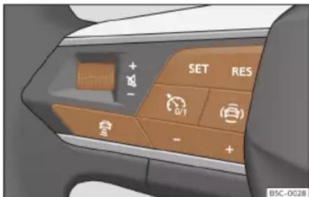
Fig. 159 On the multifunction steering wheel: buttons to operate the ACC
Connecting
- Press the 📄 button on the multifunction steering wheel.
The ACC does not regulate anything yet (standby).
Start regulation
Activating the ACC system automatically activates the ESC and ASR.
- To start regulation, press the button SET >> Fig. 159.
The ACC sets the current speed, or the closest speed within the valid range (30-210 km/h), as the cruise speed.
Driving
Depending on the driving situation, the following indicator lamps come on:

It lights up green
ACC connected, no vehicle detected in front.

It lights up green
ACC connected, vehicle detected in front.
When the ACC is in standby, the indicator lamps light up grey.
Setting speed
To program the speed, press the+or - »» Fig. 159 buttons to the desired speed. The speed is adjusted at intervals of 10 km/h (5 mph).
When the ACC is active, the button RES can be pressed to increase the desired speed by 1 km/h (1 mph). You can then press SET to decrease it by 1 km/h (1 mph).
Setting your distance level
The distance can be set to one of five levels, from very short to very long:
- Press the button 📋 and then the button + or - >> Fig. 159.
• Alternatively, press the button ☑ as many times as necessary to set the desired distance.
Keep in mind each country's regulations on minimum braking distances.
Suspend regulation (standby)
- Briefly press the button on the multifunction steering wheel or press the brake pedal.
The ACC indicator lamp is grey; the speed and distance are saved.
Reinstating the cruise control
- Press the RES button.
The ACC regulates to the last speed and distance setting.
Switching off
- Press and hold the button Ⓜ. The set speed is cleared.
Exceeding the speed regulated by the ACC
While driving with the ACC switched on, the driver can increase speed by pressing the accelerator pedal. ACC regulation is suspended until you release the accelerator pedal

Set the default distance setting
In the Infotainment system, you can pre-select the distance level when connecting the ACC from:
- Very short, Short, Medium, Long and Very long using the Infotainment system: □ > Assistants > Smart Assistants > ACC
page 89.
Changing the driving profile
In vehicles with Drive Profile, the driving profile selected can have an influence on the ACC's acceleration and braking behaviour >> page 226.
On vehicles with a Drift driving profile, ACC will be deactivated when this is selected and ACC regulation cannot be started until another profile is selected.
In vehicles without Drive Profile, the behaviour of the ACC can also be affected if any of the following drive profiles are selected in the infotainment system in Driver assistance. ACC settings will be the same as those in the Drive Profile.

WARNING
Before driving off, check that the road is clear. The radar sensor may not detect obstacles on the road. This could cause an accident and serious injuries. If necessary, apply the brake.

CAUTION
If you increase speed using the accelerator pedal, the ACC may not be able to safely
Driver assistance systems
adjust the speed of the distance due to the limitations of the system.
- Be prepared to react if required by the situation.
Status display

Fig. 160 On the instrument panel display: ACC active.
① Vehicle ahead detected. It will light up if the distance to the vehicle is adjusted.
② Selected distance level 2.
This information can be displayed on the central panel of the Assists view, or in the left hand information profile» page 65. If these views are not selected, it will be automatically displayed in the lower central part
of the instrument cluster in a simplified manner.
The set speed will be displayed next to the function status indicator described in >>> page 245, Start regulation.
Special driving situations

Fig. 161 On the instrument panel display: ACC active, vehicle detected in an outer lane.
Be aware of the limitations and warnings described at the beginning of this chapter.
▲ in Introduction on page 244.
Avoid undertaking on the right 1)
If a vehicle is detected in the left lane that is travelling at a speed slower than that set by the driver, it will brake the vehicle within the comfort limits of the system to avoid passing it on the right>> Fig. 161.
You can cancel this regulation by changing the set speed or by pressing the accelerator pedal.
The function works at speeds over 80 km/h (50 mph). It may not be available in certain countries.
Overtaking
When the turn signal is switched on for overtaking, the ACC reduces the distance from the vehicle in front to help with the overtaking manoeuvre. The set cruising speed will not be exceeded.
The function works at speeds over 80 km/h (50 mph). It may not be available in certain countries.
Stop&Go function
The ACC can bring the vehicle to a standstill (0 km/h) if the vehicle in front stops. With manual gearboxes you will need to keep the »
Driving
clutch pedal depressed to allow the car to come to a complete stop.
The ACC remains active and the message ACC ready to start is displayed on the instrument cluster for a few seconds. You can extend or reactivate this warning by pressing the button RES or, depending on your vehicle's equipment, by grabbing the steering wheel. During this time, the vehicle will move off again if the vehicle in front moves forwards.
To move off when the message ACC ready to start is not longer displayed, once the vehicle in front has moved off:
- Briefly depress the accelerator pedal (and gently lift the clutch pedal on vehicles with manual gearboxes).
The ACC is deactivated while stopped in the following cases:
• If the vehicle stops for several minutes.
- If a door is opened.
WARNING
If the message ACC ready to start is displayed on the instrument cluster display and the vehicle in front moves off, your vehicle will move off automatically. In this case, any obstacles in the road may not be detected. This may cause serious accidents and injuries.
• Always check the road before moving off, and apply the vehicle brakes yourself if necessary.
ACC system limitations

Fig. 162 A Vehicle on a bend. B Motorcyclist ahead, out of range of the radar sensor.

The limits of the ACC system mean that it is not appropriate in all situations»» △in Introduction on page 244.
CUPRA does not recommend using the function in the following cases >> △:
• Heavy rain, snow or fog.
- When going through tunnels.
• In sections with roadworks.
- On routes with curves, e.g. on mountain roads.
- On off-road routes.
• In covered car parks.
Driver assistance systems
- On roads with embedded metal objects such as train or tram tracks.
• On roads with loose gravel.
Pay special attention when using ACC in the following situations:
On curves
The ACC may not detect the vehicle in front on a curve, or may regulate the distance from vehicles in other lanes»» Fig. 162 A.
Vehicles outside the sensor zone
In the following situations the ACC may not react, or may react slowly or inappropriately:
- Vehicles that are not aligned while driving or that are outside the sensor's detection area, such as motorcycles>> Fig. 162 B
- Vehicles that move into your lane, a short distance from your vehicle >> Fig. 163 c.
• Vehicles with loads or accessories that protrude from the sides, rear or roof.
Objects that are not detected
The ACC function only detects and reacts to vehicles moving in the same direction. Therefore it does not detect:
• People
- Animals
• Vehicles travelling in the opposite direction or crossing the road.
• Other stationary obstacles
The ACC may not react to stationary vehicles. If, for example, a vehicle detected by the ACC turns or moves over and there is a stationary vehicle in front of it, the ACC will not react to the second vehicle>> Fig. 163 D
WARNING
Using the ACC in the above situations can cause serious accidents and injuries, and you could break the law.
Problems and solutions
ACC not available
The indicator lamp lights up yellow:
- The radar sensor is dirty or adjusted incorrectly. Take into account the warnings described at the beginning of this chapter >> page 233
- There is a fault or defect. Turn off the vehicle's ignition and turn it on again after a few minutes.
- If the problem persists, consult a specialised workshop.
The ACC does not work as expected
- Make sure that the conditions are met for the radar sensor to operate properly » page 233.
- If the brakes overheat, regulation stops automatically. Wait for them to cool down and check the operation again.
- Unusual noises during automatic ACC braking are normal and do not indicate any anomalies.
The following conditions may lead the ACC not to react:
• The accelerator or brake is depressed.
- No gear is engaged or the vehicle is in gear R.
• The vehicle is reversing.
- ESC is operating.
• The driver is not wearing his/her seat belt.
• A vehicle or trailer brake light is faulty.
• The RPM is too high or too low.
• The parking brake is applied.
- Driving on an excessive slope.
Driving
Proactive speed adjustment
Introduction
The proactive speed adjustment adapts the speed to the speed limitations detected and to the road layout (curves, crossings, roundabouts, etc.).
Proactive speed adjustment is an additional function of the ACC>> page 244 and uses the traffic signal detection system>> page 73 and the navigation data of the infotainment system.
Proactive speed adjustment is available depending on the equipment, although not in all countries.
WARNING
The proactive speed adjustment smart technology cannot overcome the limits imposed by the laws of physics and it only works within the limits of the system. Never allow the enhanced convenience of this function induce you to take any risk that compromises safety. If used negligently or involuntarily, it may cause serious accidents and injuries. The system is not a replacement for driver awareness.
• Always adapt your speed to suit visibility, weather, road and traffic conditions.
• Always pay attention to traffic and always keep the vehicle environment in mind.
• Always be prepared to adjust the speed yourself. If the traffic signal detection system is not working properly or the navigation data is not up to date, the speed may change unexpectedly and suddenly or may not suit the current traffic situation. In addition, the speed adjusted by the system may not suit your driving style.
• Always be prepared to adjust the speed yourself. If you drive without any active guided route, if you leave the route calculated by the navigation system or if the position of the vehicle cannot be determined correctly because the GPS does not provide accurate data, the speed may change unexpectedly and suddenly or may not adapt to the current traffic situation.
• Always use up-to-date navigation data.
• Always take into account the maximum permitted speed. In the case of speed limitations that are not included in the navigation data, the maximum permitted speed may be exceeded.
Note
Also note the information related to the ACC relevant to safety»» page 244.
Limitations of the proactive speed adjustment
In addition to the limitations of the traffic signal detection system» page 73 and of the limitations of the ACC, proactive speed adjustment has the following limitations inherent to the system:
- Proactive speed adjustment only recognises traffic signals that show a speed limitation. The proactive speed adjustment does not take into account, above all, the rules on priority of passage or traffic lights.
- On roads that are not included in the navigation data, or that are included with little accuracy, proactive speed adjustment is not available.
- If a speed limitation is notified based on the navigation data without it being detected by the traffic signal detection system, the indicated speed will be adjusted to the speed that was saved the last time.
- Proactive speed adjustment is not available for speed limitations below approx. 20 km/h (approx. 15 mph). In this case, a relevant message is displayed on the instrument panel screen.
Driver assistance systems
Activating the proactive speed adjustment
In the infotainment system, in the assist services menu, you can individually adjust the type of incident the vehicle should react to >> page 89:
- Response to road layout.
- Reaction at permitted speeds.
Driving with the proactive speed adjustment
- Connect the ACC» page 245.
- Set distance and speed.
- Activate the proactive speed adjustment.
As soon as the system recognises a speed limitation or a relevant road layout during the route, a warning will appear on the instrument panel display. This warning will indicate the reason and the speed to which the vehicle will adjust due to said limitation.

Adjustment due to a speed limitation.

Adjustment due to a road layout.
In the event of adjustment due to a speed limitation, the detected speed will be saved as the new desired speed. In the event of ad-
justment due to the road layout, the vehicle will accelerate again after leaving the reason for the adjustment behind and the speed will be adjustment to that which has been saved.
The speeds indicated for curves depend on the driving profile»»page 226.
Interrupting speed adjustment
- During the warning, press the button RES.
- During the adjustment, press the button SET.
Adjust the announced speed
The announced speed can only be adjusted in the event of adjustment due to a speed limitation.
Multifunction steering wheel:
RES + 1 km/h (1 mph), only while the ACC is adjusting
SET - 1 km/h (1 mph), only while the ACC is adjusting
+ +10 km/h (5 mph)
- 10 km/h (5 mph)
If you adjust the indicated speed excessively, the proactive speed adjustment is interrupted.
Note
- When a speed limitation is recognised, the proactive speed adjustment also adapts the saved speed even if the ACC is switched off. However, it will not adjust.
- If the speed of travel considerably exceeds the speed limit detected by the traffic signal detection system, a relevant warning is displayed in the instrument panel display.
- In the event of joining a highway without speed limitation, the recommended speed is automatically saved as the desired speed. If a higher speed has previously been saved for a motorway without a speed limit, this is used instead of the recommended speed.
Problems and solutions
A message is displayed indicating that proactive speed adjustment is not currently available or not in your country.
- If this message is displayed for a long time and proactive speed adjustment is available in your country, contact a specialised workshop.
Note
Depending on the anomaly in question, additional information may be displayed in Vehicle status»» page 88.
Driving
Lane Assist
Introduction
The Lane Assist System helps the driver stay in his/her lane within the physical limits of the system. This function is not suitable and is not designed to keep the vehicle automatically in the lane.
Using the camera located in the windscreen, the Lane Assist system detects the limits (lane lines) dividing the lanes in which the vehicle is travelling. If the vehicle gets too close to the detected lane limits, the system alerts the driver through a corrective motion of the steering wheel. The driver can cancel the steering corrective action at any time.
No warning is produced with the turn signals activated, given that the Lane Assist system understands that a lane change is required.
System limits
Use the Lane Assist system only on large, well-maintained motorways and highways.
The system is not available under the following conditions:
• The driving speed allowed is below approx. 55 km/h (30 mph).
- The system has not detected any lane lines.
- On tight bends.
• Temporarily in very sporty driving situations.
WARNING
The intelligent technology in the Lane Assist system cannot change the limits imposed by the laws of physics and by the very nature of the system. Careless or uncontrolled use of the Lane Assist system may cause accidents and injury. The system is not a replacement for driver awareness or manoeuvres when driving.
• Always adapt your speed and the distance to the vehicles ahead in line with visibility, weather conditions, the condition of the road and the traffic situation.
- Always keep your hands on the steering wheel so it can be turned at any time. The responsibility of staying in the lane is always the driver's.
- The Lane Assist system does not detect all road markings. The road surfaces, road structures or objects in poor condition can be incorrectly detected as road markings under certain circumstances by the Lane Assist system. Immediately counter any unwanted intervention of the system.
- Please observe the indications on the instrument panel and act as is necessary if the traffic situation permits.
• In the following situations there may be undesired interventions of the system or it
may be that the system does not intervene at all. In these situations, special attention is required from the driver and, where appropriate, the temporary deactivation of the lane assist warning system:
– In very sporty driving situations.
- In adverse weather conditions and roads in poor condition.
- When passing through areas undergoing works.
– Before gradient changes of grade and river beds.
• Always observe the vehicle surroundings carefully and drive proactively.
- When the area of vision of the camera becomes dirty, covered or is damaged, the Lane Assist system function can be affected.
Control lamp

It lights up green
Lane Assist system active and available.

It lights up yellow
The Lane Assist system intervening with a rectification of the steering.
Driver assistance systems

It lights up yellow
Lane Assist system
Some control and warning lamps will light up briefly when the ignition is switched on to check certain functions. They will switch off after a few seconds.
WARNING
Observe the safety warnings»» in Control and warning lamps on page 84.
Driving with the Lane Assist System
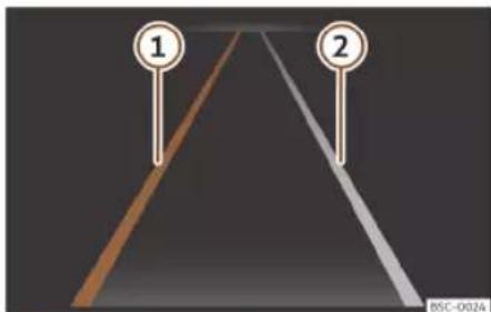
Fig. 164 On the instrument panel display: indications of the Lane Assist System.
① Lane line detected. The system intervenes assisting on the represented side.
② Lane line detected. The system does not intervene.
Switching the lane assist system on or off
In some countries, the Lane Assist System is always activated when the ignition is switched on. The connection status is shown in the Driver assistance menu of the Infotainment system or the driver assistance systems menu after pressing the corresponding button. The Lane Assist system can be activated and deactivated in these menus.
The Lane Assist system is ready to actively intervene as of approximately 60 km/h (35 mph) and if it has detected the lane limits (system status: active). The control lamp emits a green light. When the system intervenes by rectifying the direction, the control lamp emits a yellow light.
If the control lamp of the instrument panel display is off, it means that the Lane Assist system is connected but not ready to intervene or it is disconnected.
When you activate a turn signal, the system temporarily goes into a passive state in order to allow manual lane change.
An energetic rotation or rectification of the steering wheel by the driver causes the system to temporarily switch to a passive state.
Driver intervention prompt
If the steering is not corrected manually, the system prompts the driver through an indication on the instrument panel display and acoustic warnings.
If no reaction is obtained from the driver, the system switches to a passive state.
Regardless of the steering manoeuvres, through an indication on the instrument panel display and acoustic warnings, the driver is also prompted to drive through the centre of the lane if the steering correction lasts more than reasonable.
Steering wheel vibration
The following situations may result in a steering wheel vibration:
- The lane ceases to be recognised during a sudden intervention in the direction of the system.
It is also possible to select steering wheel vibration in the Assistants menu of the infotainment system. In this case, when a vehicle with Lane Assist switched on crosses over a detected lane marking, the steering wheel will vibrate.
Driving
Troubleshooting
Error message, the system disconnects
- Clean the windscreen.>>> page 353
- Check that the windscreen is not damaged in the area of the camera's field of vision.
System behaviour is different than expected
- Clean the field of vision of the camera regularly and make sure it is free of dirt, snow and ice.
- Do not cover the field of vision of the camera.
- Check that the windscreen is not damaged in the area of the camera's field of vision.
- Do not mount objects on the steering wheel.
In the event of doubts or queries, go to a specialised workshop.
Driving Assist (Travel Assist)
Introduction
The driving assist (Travel Assist) combines adaptive cruise control (ACC) and adaptive lane guidance. Within the limitations of the system, the vehicle can maintain a
distance from the vehicle in front that is preselected by the driver and remain in the preferred position within the lane.
Travel Assist uses the same sensors as Adaptive Cruise Control (ACC) and Lane Assist. Therefore, carefully read the information about the ACC» page 244 and the Lane Assist» page 252 and take into account the limitations of the systems and the indications given in the information.
Speed range
Travel Assist adjusts at speeds between approx. 30 km/h (approx. 20 mph) and approx. 210 km/h (approx. 130 mph); in the case of the adaptive lane guidance function, between 0 km/h (0 mph) and approx. 250 km/h (approx. 155 mph).
Driving with Travel Assist
Travel Assist automatically controls the accelerator pedal, the brakes and the steering. In addition, Travel Assist may, within its limitations, decelerate the vehicle until it stops behind another that stops and automatically starts again.
You can override assisted adjustment at all times.
How to know if the vehicle is fitted with Travel Assist
The vehicle is fitted with Travel Assist if the multifunction steering wheel has the button Fig. 167.
Driver intervention prompt
If you remove your hands from the steering wheel, after a few seconds the system asks you to take over the steering with an indication on the instrument panel display and acoustic warnings.
WARNING
The Travel Assist smart technology cannot overcome the limits imposed by the laws of physics and it only works within the limits of the system. If Travel assist is used negligently or involuntarily, it may cause serious accidents and injuries. The system is not a replacement for driver awareness.
- Bear in mind the system limitations and the indications regarding the control of the Adaptive Cruise Control (ACC) and Lane Assist.
- Adapt your speed and safety distance to the vehicle in front of you at all times to suit visibility, weather, road and traffic conditions.
- Do not use Travel Assist when visibility is bad, on steep roads, on windy roads or in slippery circumstances (such as snow, ice, rain or loose gravel), or on flooded roads.
Driver assistance systems
- Do not use Travel Assist offroad or on roads where the surface is not firm. Travel Assist has been designed for use on paved roads only.
- Travel Assist does not react to people or animal or vehicles crossing your path or which approach you head-on in the same lane.
- Brake immediately if Travel Assist does not slow down enough.
- Brake immediately when a braking message is displayed on the instrument panel screen.
- Brake when, after an indication to brake, the vehicle rolls without it being desired.
- Keep your hands on the steering wheel at all times, to ensure you have control over the steering at all times. The driver is always responsible for keeping the vehicle in its own lane.
- If possible, do not wear gloves while driving. The system could interpret this as no driving activity.
- If driver intervention is requested on the instrument panel display, immediately resume control of the vehicle.
• Always be prepared to adjust the speed yourself.
Indications on the instrument panel display

Fig. 165 On the instrument panel display: indication with active adjustment.

Fig. 166 On the instrument panel display: control lamps.
Displays on the screen
Fig. 165
① The adaptive lane guidance function is active.
② Distance set.
In addition, depending on the equipment, control lamps indicate the status of the system on the instrument panel display:
>>> Fig. 166
A Travel Assist active, adaptive cruise control and adaptive lane guidance function are active.
B Travel Assist active, adaptive cruise control active and adaptive lane guidance function passive.
Travel Assist active, adaptive cruise control passive and adaptive lane guidance function active.
(D) Travel Assist active, adaptive cruise control and adaptive lane guidance function are passive.
E Inactive Travel Assist.
Depending on the equipment, more details may be displayed on the instrument cluster, such as dashed lines or other vehicles on the road.
Driving
Operating Travel Assist

Fig. 167 Left side of the multifunction steering wheel: buttons for operating Travel Assist.
Connecting
- Press the 🔊 button on the multifunction steering wheel.
The control lamp, will light up green. The following warning is also displayed on the instrument panel screen: The Travel Assist maintains the current speed and the preset distance from the vehicle in front. At the same time, if it detects road markings it keeps the vehicle in the lane by moving the steering wheel.
Interrupting the adjustment
- Briefly press the button on the multifunction steering wheel or press the brake pedal.
The set distance remains saved.
Making other adjustments
For all else, Travel Assist is operated like the ACC>> page 245.
Problems and solutions
Travel Assist is not available or does not work as expected
The control lamp switches on yellow. A relevant warning is also displayed on the instrument panel screen.
- There is a fault in the sensors. Check the causes and solutions described in » page 233.
• The system limits are exceeded. - If the fault continues, consult a specialised workshop.
Take the wheel
The warning lamp comes on white or red, depending on the urgency of the intervention. A message is also displayed.
- You released the steering wheel for a few seconds. Take hold of the steering wheel and take control of the vehicle.
- The system limits have been reached. Take hold of the steering wheel and take control of the vehicle.
Travel Assist disconnects automatically
Vehicles without Emergency Assist: You have released the steering wheel for a long period.
- Abnormal operation. Contact a specialised workshop.
The adjustment is interrupted unexpectedly
Vehicles without lane departure warning: You have turned on the turn signal.
Emergency Assist
How it works
Emergency Assist can detect whether there is inactivity by the driver and can automatically keep the car within the lane and stop it altogether if necessary. This way the system can actively help avoid an accident or reduce its consequences.
Emergency Assist uses the same sensors as Adaptive Cruise Control (ACC) and Lane Assist. Therefore, carefully read the information about the ACC» page 244 and the
Driver assistance systems
Lane Assist >> page 252 and take into account the limitations of the systems and the indications given in the information.
If the Emergency Assist detects that the driver does not perform any activity, it requests that the driver take control of the vehicle. To do this, it emits optical and acoustic warnings and causes braking jolts. The seat belt is tightened (depending on the equipment). The system slows down the vehicle and keeps it in its lane.
You can cancel the adjustment at any time by moving the steering wheel, over-accelerating or braking.
While the emergency assistant is in operation, other road users are warned as follows:
- The hazard warning lights are switched on soon after.
- The horn sounds (depending on the speed).
The following happens as soon as the vehicle stops:
- All doors are unlocked.
• The interior lighting comes on. - Depending on the equipment, an emergency call (eCall) is made.
- The electronic parking brake and gear shift position P are engaged.
Connecting and disconnecting
Emergency Assist can be connected and disconnected in the infotainment system, in the assist services menu»» page 89.
When connected, the Emergency Assist is only activated if the following requirements are met:
- The Travel Assist or the Lane Assist are switched on.
- The system has detected a road lane marking on both sides of the vehicle.
Troubleshooting
Emergency Assist not available SOS
The control lamp switches on yellow. A relevant warning is also displayed on the instrument panel screen.
- The field of vision of the camera is dirty. Clean the windscreen.
- The visibility of the camera is diminished due to weather factors, e.g. snow, or detergent residue or some coating. Clean the windscreen.
- The visibility of the camera is diminished due to accessories or adhesives. Leave the area around the camera's field of vision free.
-
The camera has been altered or damaged, e.g. because of damage caused to the windscreen. Check for visible damage.
-
There is a fault or defect. Turn the drive system off and on again.
- If the fault continues, disconnect the Emergency Assist and consult a specialised workshop.

WARNING
The smart technology fitted into the Emergency Assist cannot overcome the limits imposed by the laws of physics; it only works within the limits of the system. The driver is responsible for driving the vehicle.
- Adapt your speed and safety distance to the vehicle in front of you at all times to suit the visibility, weather, road and traffic conditions.
• The Emergency Assist cannot always avoid accidents or serious injuries by itself. - If possible, do not wear gloves while driving. The system could interpret this as no driving activity.
- If the radar sensor or the camera are covered or have been altered or damaged, the system may intervene on the brakes or on the direction in an inappropriate manner.
- The Emergency Assist does not react to people or animal or vehicles crossing your path or which approach you head-on in the same lane.
Driving

WARNING
If the Emergency Assist Intervenes inopportunely, serious accidents and injuries may occur.
- If the vehicle behaves differently than expected, interrupt the intervention of the Emergency Assist by over-accelerating, braking or moving the steering wheel.
- Do not use Travel Assist or Lane Assist. Have the system checked by a specialised workshop.

Note
• Automatic interventions by the Emergency Assist on the brakes may be interrupted by pressing the accelerator or brake or by moving the wheel.
- Hazard warning lights that come on automatically can be switched off by pressing the accelerator or the break, moving the steering wheel or pressing the hazard warning light switch.
- If this occurs, the Emergency Assist may decelerate the vehicle until it comes to a complete stop.
- When the Emergency Assist is activated, it is only available again after the ignition has been switched off and back on again.
Lane departure warning (Side Assist) with rear cross traffic alert (RCTA) and door opening warning (Exit Assist)
Introduction
The lane departure warning (LCA) helps detect traffic that is at the rear of the vehicle.
The rear cross traffic alert (RCTA) helps the driver when backing out of a parallel parking spot and when manoeuvring.
The door opening warning (EWA) alerts the occupant of a possible danger approaching from behind when opening or when any of the vehicle's doors are open.

WARNING
The smart technology incorporated into the lane departure warning (LCA) with rear cross traffic alert (RCTA) and the door opening warning included cannot overcome the limits imposed by the laws of physics; it only works within the limits of the system. Accidents and severe injury may occur if the lane departure warning or the rear cross traffic alert are used negligently
or involuntarily. The system is not a replacement for driver awareness.
- Adapt your speed and safe distance to the vehicle in front of you at all times to suit visibility, weather, road and traffic conditions.
- Keep your hands on the wheel at all times to be ready to intervene in the steering at any time.
- Pay attention to the indicator lamps that may come on in the external rear view mirrors and on the instrument cluster, and follow any instructions they may give.
- The lane departure warning could react to any special constructions that might be present to the sides of the vehicle, e.g. high or irregular dividers. This may cause erroneous warnings.
- Never use the lane departure warning on unpaved roads. The lane departure warning has been designed for use on paved roads.
• Always pay attention to the vehicle's surroundings. - The control lamps of the lane departure warning may have limited functionality due to solar radiation.

Note
If the lane departure warning with rear cross traffic alert does not work as described in this chapter, stop using it and contact a specialised workshop.
Driver assistance systems
Control lamp

Fig. 168 Control lamp of the lane departure warning.

Fig. 169 Control lamp of the lane departure warning.
It lights up
It turns on once briefly: the lane departure warning is activated and ready to operate, i.e. when activating the system.
It lights up
It lights up continuously: the lane departure warning has detected a vehicle in the blind spot.
Flashes
A vehicle has been detected in the adjacent lane and the turn signal has been engaged in the direction of the detected vehicle >> △
For vehicles that are also equipped with Lane Assist >> page 252, a warning to switch lanes will also appear even though the turn signal has not been engaged (Lane Assist "Plus" >> page 260).
The control lamps light up when the ignition is switched on and should turn off after approximately 2 seconds. This is the time taken for the function check.
If there are no indications from the control lamp of the lane departure warning, this means that the lane departure warning has not detected any other vehicles at the rear area>>> △.
When the exterior lighting is low, the intensity with which the control lamps come on is dimmed. The user can modify the intensity of the control lamps with up to 5 levels in the infotainment system menu.
WARNING
If the warning lamps and the corresponding messages are ignored when they light up,
the vehicle may stall in traffic and cause accidents and severe injuries.
- Never ignore the warning lamps or messages.
- Carry out the necessary operations.
CAUTION
Failure to heed the control lamps and corresponding text messages when they light up may result in damage to the vehicle.
Lane departure warning (Side Assist)
The lane departure warning uses radar sensors to monitor the areas behind the vehicle >> page 7. The system does this by measuring the vehicle's distance from other vehicles and its speed differential. The lane departure warning will not work at speeds of less than approx. 15 km/h (9 mph).
The lane width is not detected individually, but is rather pre-configured in the system. Thus if you are driving in wide lanes or in between two lanes, the indications may be incorrect. Furthermore, the system can detect vehicles driving in the lane next to you (if there are any), and can also detect stationary objects such as dividers, and thus give an incorrect indication.
Driving
Light indication
The control lamp provides an indication on the corresponding side regarding the traffic situation behind the vehicle, if it is deemed to be critical. The control lamp of the left-hand side >>Fig. 168 indicates the traffic situation to the rear left of the vehicle, and the control lamp of the right-hand side >>Fig. 169, indicates the traffic situation to the rear right of the vehicle.
Keep the warning lamps zone of the lane departure warning free of objects, adhesives or the likes that may interfere with your visibility.
Lane assist Plus.
The Lane Assist Plus function can be used by activating the Lane Assist>> page 252 and Side Assist functions. In this case its functions are expanded as described below.
If the driver initiates a lane change manoeuvre in a potential critical situation:
• The lamp flashes in the corresponding rear-view mirror even though the turn signal has not been activated.
• The steering wheel vibrates to warn the driver of the risk of collision.
- torque is applied to correct the steering and return the vehicle to its lane.
Driving situations

Fig. 170 Schematic representation: A Passing situation with traffic behind the vehicle. B Indication of the lane departure warning in the control lamp on the left side.

Fig. 171 Schematic representation: A Situation of an overtaking in the centre lane and then moving into the right-hand lane. B Indication of the lane departure warning in the control lamp on the right side.
In the following situations, an indication will be displayed in the control lamp>> Fig. 170 B (arrow) or>> Fig. 171 B (arrow):
- When being overtaken by another vehicle >> Fig. 170 A.
- When passing another vehicle» Fig. 171 A with a speed differential of approx. 10 km/h (6 mph). If the vehicle is passing at a
Driver assistance systems
considerably higher speed, no indication will be displayed.
The faster the vehicle approaches, the sooner an indication will be displayed in the control lamp, because the lane departure warning takes into account the speed differential with other vehicles. Thus even though the distance from the other vehicle is identical, the indication will appear sooner in some cases and later in others.
Physical limitations inherent to the system
In some situations the lane departure warning may not interpret the traffic situation correctly. I.e. in the following situations:
- on tight bends;
• in the case of lanes with different widths;
• in areas with significant gradient changes;
• in adverse weather conditions;
• in the case of special constructions to the side of the vehicle, e.g., high or irregular dividers.
Rear cross traffic alert (RCTA)

Fig. 172 Schematic representation of the rear cross traffic alert assistant: zone monitored around the vehicle while leaving a parking space.
Park Assist uses the radar sensors on the rear bumper»» page 233 to monitor the traffic crossing behind the vehicle as it backs out of a parallel parking space or as it is being manoeuvred, for example in very low visibility conditions.
When the system detects a relevant vehicle on the road that is approaching the rear of the vehicle>> Fig. 172, an acoustic alarm may sound if the relevance so requires it.
In addition to the acoustic alarm, the driver is also informed by means of a visual signal on infotainment system display. This signal is displayed in the form of a red or yellow strip at the back of the image of the vehicle on the infotainment system screen. This strip displays the side of the vehicle towards which traffic is approaching in transverse direction 1) .
Automatic braking to reduce damages
If the rear cross traffic alert detects that someone else on the road is approaching the rear of the vehicle and the driver does not step on the brake, the system will engage the brakes automatically.
The parking system helps the driver by automatically engaging the brakes to reduce any damage. The automatic intervention on the brakes takes place when driving in reverse at approx. 1-12 km/h (1-7 mph). After detecting that the vehicle is stationary, the system keeps it that way for around 2 seconds.
After automatically braking to reduce damage, the system will not be able to automatically brake again for approximately 10 seconds.
You can interrupt the automatic braking by stepping hard on the accelerator pedal or the brake pedal in order to regain control of the vehicle.
Driving

WARNING
The smart technology incorporated into the rear cross traffic alert cannot overcome the limits imposed by the laws of physics; it only works within the limits of the system. The parking assistant function should not tempt you into taking any risks. The system is not a replacement for driver awareness.
- The system should never be used in limited visibility conditions or complicated traffic, e.g., in high-traffic areas or when crossing multiple lanes.
- Be sure to always be aware of the vehicle's surroundings, since the system often fails to detect things such as bicycles or pedestrians.
• The rear cross traffic alert itself will not brake the vehicle to a complete stop.
Door opening warning (Exit Assist)
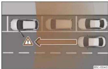
Fig. 173 Graphic example
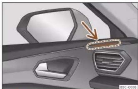
Fig. 174 Door: warning lamp
The door opening warning (Exit Assist) warns occupants of a possible collision when opening the door when the vehicle is stationary. The system monitors, within the limits of the system itself, the rear and side environment of the vehicle using the rear sen-
sors»» page 233. It detects moving objects that approach from behind, such as cars »» Fig. 173.
If a critical situation is detected when the door is opened, it will be alerted by an acoustic signal on the door speaker of the corresponding side»» Fig. 174. Additionally, the control lamp of the lane departure warning of the corresponding door will flash. If the door has already been opened and another road user has been detected in a critical situation, the control lamp of the lane departure warning on the corresponding side will light up permanently.
The brightness of the door opening warning indication cannot be adjusted.
When you want to access the vehicle for the first time, with the doors closed and locked, the function will be available 3 minutes after the first opening of any of the doors. The function will continue to be available as long as the vehicle has the ignition connected and is not moving.
After switching off the ignition, the function will remain available for approximately 3 minutes. After that time, the control lamps will light up indicating the deactivation of the function.

WARNING
• Always pay close attention to the traffic and the surroundings of the vehicle. The
Driver assistance systems
door opening warning (Exit Assist) cannot replace the necessary attention to be paid by the vehicle's occupants. The responsibility for opening the doors and exiting the vehicle always lies with the occupants of the same.
- The door opening warning (Exit Assist) operates continuously as long as the vehicle ignition is on. Otherwise, the system is deactivated and the lamps light up briefly.
- It is possible that the traffic situation is not interpreted correctly and you cannot be aware of all the objects that are approaching, such as pedestrians. Always visually monitor the traffic and the area surrounding the vehicle.
WARNING
The door opening warning (Exit Assist) is subject to system limits and cannot warn of an imminent collision in all cases:
- If your vehicle is too deep in the parking space and the adjacent vehicles hide it.
• In certain circumstances, objects or people who approach, e.g. on a bicycle or scooter, are not detected. - The system does not react to stopped objects.
Managing the assist systems
Enabling and disabling the assist systems
Side Assist, Exit Assist and the Rear Cross Traffic Alert (RCTA) can also be switched on and off from the Assistants menu of the infotainment system.
Exit Assist and Rear Cross Traffic Alert (RCTA) can also be found in the Park Assist Settings menu.
Side Assist and the Rear Cross Traffic Alert (RCTA) can also be switched off and on in the instrument cluster Assistants menu >> page 69.
Open the Assistants menu in the infotainment system.
- □ Side Assist
- □ Door opening warning
- □ Rear cross traffic alert
Open the Park Assist > Settings menu in the infotainment system.
- □ Door opening warning
- □ Rear cross traffic alert
Open the Assistants menu on the instrument cluster
- □ Side Assist
- □ Rear cross traffic alert
If the verification box on the instrument panel or the infotainment system is checked ☑, the functionality will be automatically activated when switching on the ignition.
When the lane departure warning is ready to operate, the indications in the control lamps will turn on briefly as confirmation.
When the vehicle is restarted, the last adjustment in the system will remain active.
Trailer mode
The lane departure warning, the rear cross traffic alert and the door opening warning will be automatically deactivated and will be prevented from reactivating if the factory-mounted tow hook is electrically connected to a trailer or other similar device.
As soon as the driver starts to drive with a trailer connected electrically to the vehicle, a message will appear on the instrument panel display indicating that the lane departure warning, the rear cross traffic alert and the door opening warning are deactivated. Once the vehicle trailer has been disengaged, the lane departure warning, the rear cross traffic alert and the door opening warning will return to the initial state prior to the moment the trailer was electrically connected.
If the towing hook is not factory-mounted, then the lane departure warning, the rear cross traffic alert and the door opening
》
Driving
warning will have to be deactivated manually when driving with a trailer.
Braking and parking
Braking system
Control lamps
(①) It lights up red
Brake fluid level too low»» page 331 or fault in the brake system.
Do not carry on driving!
(P) It lights up red
Electronic parking brake>>> page 266. The warning lamp turns off when the handbrake is released.
It lights up yellow
Front brake pads worn. Contact a specialised workshop immediately.
WARNING
- When the ignition is switched on, the status of the brake system and the brake assist functions is automatically checked. The control lights on the instrument cluster light up briefly and then turn off again. If a warning light stays on permanently, there is a fault. Seek qualified technical assistance immediately.
- If the brake warning lamp (1) does not go out or if it lights up when driving, the brake
fluid level in the reservoir is too lo so there is a risk of an accident»» page 331, Brake fluid. Stop the vehicle and do not drive on. Obtain technical assistance.
- If the brake warning lamp lights up together with the ABS lamp this could be due to an ABS fault. When this function fails, the rear wheels can lock up. Under certain circumstances, the rear of the vehicle may skid, with the danger of losing control. Stop and seek technical assistance.
- If the lamp lights up, alone or accompanied by a warning message on the instrument panel display, please go immediately to a specialised workshop to check the brake pads and to replace them if they are worn.
Information about the brakes
New brake pads
For the first 200 to 300 km (100 to 200 miles), new brake pads have not yet reached their maximum braking capacity, and need to be "run in" first. However, you can compensate for the slightly reduced braking effect by applying more pressure on the brake pedal. Avoid overloading the brakes while running them in.
Braking and parking
Wear
The rate of wear on the brake pads depends a great deal on how you drive and the conditions in which the vehicle is operated. This is a particular problem in urban traffic and short stretches, or with very sporty driving.
Depending on the speed, the braking force and the environmental conditions (e.g. temperature, air humidity, etc.) noises may be produced when braking.
Wet roads or road salt
In certain situations (for example, on driving through flooded areas, in severe downpours or after washing the vehicle) the braking action could be delayed if the discs and pads are damp, or frozen in winter. In this case the brakes should be "dried" by pressing the brake pedal several times.
At high speed and with the windscreen wipers activated, the brake pads will briefly touch the brake discs. This takes place, although unnoticeable to the driver, at regular intervals to improve the response time of the brakes when they are wet.
The effectiveness of the brakes can also be temporarily reduced if the vehicle is driven for some distance without using the brakes when there is a lot of salt on the road in winter. The layer of salt that accumulates on the discs and pads can be removed by gently applying the brakes a few times.
Corrosion
There may be a tendency for corrosion to form on the discs and dirt to build up on the brake pads if the vehicle is used infrequently or the brakes are not used very often.
If the brakes are not used frequently, or if rust has formed on the disks, it is advisable to clean off the pads and disks by braking firmly a few times at a moderately high speed>> △.
Fault in the brake system
If the brake pedal travel should ever increase suddenly, this may mean that one of the two brake circuits has failed. Drive immediately to the nearest specialised workshop and have the fault repaired. Drive there slowly and remember that you will have to apply more pressure on the brake pedal and allow for longer stopping distances.
Low brake fluid level
Malfunctions can occur in the brake system if the brake fluid level is too low. The brake fluid level is monitored electronically.
Brake servo
The brake servo increases the pressure you apply to the brake pedal. It works only when the engine is running.
Electromechanical brake servo (eBKV)
The electromechanical brake servo only works when the ignition is switched on and optimises the force of the foot by increasing the pressure that the driver exerts on the brake pedal.
If the electromechanical brake servo is not working, the brake pedal must be pressed harder, as the braking distance increases due to the lack of assistance from the servo brake.
WARNING
Any anomaly in the brake system can increase the braking distance, with the resulting risk of an accident.
- New brake pads and discs must be run in and do not have the correct friction during the first 200km (124 miles). This reduced braking capacity may be offset by pressing on the brake pedal a little harder.
- If you are driving on roads which have been salted, braking effectiveness may be decreased.
- Brakes can overheat if used excessively on slopes. Before driving down a long steep slope, it is advisable to reduce speed and change down into a lower gear or range. Therefore, using the engine brake relieves the brakes.
Driving
- Gentle continuous braking causes the brakes to overheat and the braking distance will increase. Apply and then release the brakes alternately.
- Apply the brakes heavily to clean the brake system only in a suitable traffic situation. Do not put other road users in danger: there is risk of causing an accident.
- Ensure the vehicle does not move while in neutral, when the engine is stopped. The braking distance is increased considerably when the brake servo is not active.
- If the brake is subjected to high stresses, vapour bubbles may form in the brake system's pipes. This reduces the efficiency of the brakes.
- Non-standard or damaged front spoilers could restrict the airflow to the brakes and cause them to overheat. Before purchasing accessories please read the relevant instructions.

CAUTION
- Never let the brakes "drag" by leaving your foot on the pedal when it is not necessary to brake. This overheats the brakes, resulting in longer stopping distances and greater wear.
- Before driving down a long, steep gradient, it is advisable to reduce speed and select a lower gear. This makes use of engine braking and relieves the brakes. If you still have to use the brakes, it is better to brake
firmly at intervals than to apply the brakes continuously.
Note
- If the brake servo is out of action, for example when the car is being towed, you will have to press the brake pedal considerably harder than normal to make up for the lack of servo assistance.
- If you wish to equip the vehicle with accessories such as a front spoiler or wheel covers, it is important that the flow of air to the front wheels is not obstructed, otherwise the brakes can overheat.
Electronic parking brake (EPB)
Fig. 175 In the lower part of the centre console: electronic parking brake button
The electronic parking brake replaces the handbrake >> ⚠.
Applying the electronic parking brake
The electronic parking brake can be activated whenever the vehicle is at a standstill, even when the ignition is switched off. Activate it whenever you leave or park the vehicle.
- Pull and hold the Ⓞ>>> Fig. 175 button.
- The parking brake is activated when the control light of button» Fig. 175 and the red@ control lamp on the instrument panel is always on.
- Release the button.
Disconnecting the electronic parking brake
- Switch the ignition on.
- Press the button(2)» Fig. 175. At the same time step hard on the brake pedal or, if the engine is running, press the accelerator pedal slightly.
- The control lamp of button>>Fig. 175 (arrow) and the red® control lamp on the instrument panel go out.
Automatic release of the electronic parking brake upon moving off
The electronic parking brake is automatically switched off when starting if, after the driver's door is closed and the driver's seat belt fastened, any of the following situations take place:
Braking and parking
- In vehicles with automatic gearboxes: a gear is engaged or changed to another and the accelerator is pressed gently.
- In vehicles with manual gearboxes: the clutch pedal is pressed fully before starting off and the accelerator is pressed gently.
- To facilitate certain manoeuvres there are exceptions that allow the automatic parking brake to be released without the driver's seat belt being fastened.
The parking brake can be prevented from being automatically released by continuously pulling up the ②>>> Fig. 175 switch when starting off.
The electronic parking brake is not disconnected until the Ⓐ button is released. This can facilitate starting off when a heavy load is towed»» page 291.
Automatic activation of the electronic parking brake when exiting the vehicle incorrectly
In vehicles with automatic transmission, the electronic parking brake is activated automatically when exiting the vehicle incorrectly if:
- The selector lever is in the D/S or R or is in tiptronic mode.
• AND: the vehicle is stationary.
• AND: the driver door is open.
Automatic activation of the electronic parking brake when turning the ignition off
In vehicles with manual transmission, the electronic parking brake is activated automatically when turning the ignition off. This function can be deactivated through the Infotainment system» page 89.
Emergency brake function
Only use the emergency brake function if you are unable to stop the vehicle with the foot brake» △.
- Pull and hold the (P)>> Fig. 175 button in this position to forcefully brake the vehicle. At the same time, an acoustic warning can be heard.
- To stop the braking process, release the (P) button or press the accelerator.
When the ESC "Sport" or ESC OFF mode is selected, ESC will reactivate to assist the driver during braking. Depending on the model version, the ESC will either switch back to its previous disconnected state or will remain on.
WARNING
The improper use of the electronic parking brake can cause accidents and serious injury.
- Never use the electronic parking brake to stop the vehicle, unless it is an emergency. Braking distances can be considerably longer, since, under certain circumstances, only the rear wheels brake. Always use the foot brake.
- Never accelerate from the engine when a gear range or a gear is engaged and the engine is running. The vehicle could move, even if the electronic parking brake is activated.
- When the electronic parking brake is switched on or off, there is a slight movement of the brake pedal. Be careful not to position your foot under the pedal.
CAUTION
To prevent the vehicle from unintentionally moving when parking it, first apply the electronic parking brake and then remove your foot from the brake pedal.
Note
- In vehicles with manual transmission, when you release the clutch pedal and accelerate at the same time, the electronic parking brake is automatically disconnected.
- If the vehicle battery is flat, it will not be possible to disconnect the electronic parking brake. Use the jump-start»» page 52.
Driving
- When the electronic parking brake is applied or released, noises may be heard.
- The system performs automatic and audible tests sporadically in the parked vehicle if some time elapses without the electronic parking brake being used.
Auto Hold Function

Fig. 176 In the lower part of the centre console: Auto Hold function button.
The indicator lamp of the Auto Hold >> Fig. 176 button remains on when the Auto Hold function is connected.
Once connected, the Auto Hold function assists the driver in keeping the vehicle stationary at repeated intervals or for a certain period of time with the engine running, for example, when going up a slope, when stopped at traffic lights or in heavy traffic with intermittent stops.
When connected, the Auto Hold function automatically prevents the vehicle from rolling when stationary without pressing the brake pedal.
After detecting that the vehicle is stationary and the brake pedal has been released, the Auto Hold function holds the vehicle. The driver can lift their foot off the brake pedal.
When the driver touches the accelerator pedal or accelerates slightly to continue driving, the Auto Hold function releases the brake. The vehicle moves according to the slope of the road.
If the vehicle is stationary and one of the conditions required by the Auto Hold function is impaired, it disconnects itself and the button's control light goes out»»Fig. 176. The electronic parking brake connects automatically, if necessary, to park the vehicle safely»» △.
Conditions for keeping the vehicle stationary with the Auto Hold function
• The driver door must be closed.
• The driver's seat belt must be fastened.
• The engine is running.
Switching the Auto Hold function on and off
Press the Auto Hold button» The control lamp on the button goes out when the Auto Hold function is switched off.
Automatically engaging and disengaging the Auto Hold function
If the Auto Hold function was switched on via the Auto Hold button before switching the ignition off, the function will remain on the following time the ignition is switched on.
If the Auto Hold function was not switched on, it will automatically remain off next time the ignition is engaged.
The Auto Hold function connects automatically if the following conditions are met (all points must be met at the same time >> △):
- The vehicle is kept stationary with the brake pedal on a flat surface or on a slope.
- The engine rotates "correctly".
The Auto Hold function is automatically turned off if the following conditions are met:
- If any of the conditions mentioned on >> page 268, Conditions for keeping the vehicle stationary with the Auto Hold function are no longer met.
Braking and parking
- If the engine is running irregularly or an anomaly is detected.
- If the engine stalls.
- Manual gearbox: If the clutch and the accelerator are pressed at the same time.
Automatic gearbox: If the accelerator is pressed
- Automatic gearbox: If any of the tyres has only minimal contact with the ground, e.g. in the case of axle articulation.

WARNING
The smart technology incorporated into the Auto Hold function cannot defy the laws of physics; it only works within the limits of the system. The greater convenience provided by the Auto Hold function should never tempt you to take any risk that may compromise safety.
- Never leave the vehicle running and with the Auto Hold function switched on.
- The Auto Hold function cannot always keep the vehicle stationary uphill or downhill or stop it sufficiently, for example, on slippery or frozen surfaces.

Note
Before entering a car wash, always switch off the Auto Hold function, because if the
electronic parking brake is automatically connected, it may cause damage.
Stabilisation and brake assistance systems
Control lamps

It lights up
Fault in the ESC or ABS, or disconnection caused by the system. The ESC works in combination with the ABS. If the ABS fails, the lamp also lights up.

Flashes
ESC or TCS activated.

It lights up
TCS manually deactivated.
Or: ESC in Sport mode >> page 272.
Or: ESC manually deactivated >> page 272.

It lights up
ABS faulty or does not work.

WARNING
When the ignition is switched on, the status of the brake system and the brake assist functions is automatically checked. The control lights on the instrument cluster light up briefly and then turn off again. If a warning light stays on permanently, there is a fault. Seek qualified technical assistance immediately.
Brake assist systems
Electronic Stability Control (ESC)
The ESC helps to improve safety. It reduces the tendency to skid and improves the stability and roadholding of the vehicle. The ESC detects critical handling situations, such as vehicle understeer or oversteer, or wheel-spin on the driving wheels. It stabilises the vehicle by braking individual wheels or by reducing the engine torque. The warning lamp will flash on the instrument panel when the ESC is intervening.
The ESC includes the anti-lock brake system (ABS), the hydraulic brake assist (HBA), the traction control system (TCS), electronic differential lock (EDS), electronic torque control (XDS) and the tractor-trailer sway mitigation.
ESC also helps stabilise the vehicle by changing the torque.
Driving
The TCS can be deactivated when wheel spin is desirable >> page 272.
Anti-lock brake system (ABS)
ABS prevents the wheels from locking up under braking until the vehicle has reached a virtual standstill. You can continue to steer the vehicle even when the brakes are on full. Keep your foot on the brake pedal and do not pump the brakes. You will feel the brake pedal pulsate while the ABS is working.
If the running gear or brake system is modified, the effectiveness of the ABS could be severely limited.
Hydraulic Brake Assist (HBA)
The brake assist system can reduce the required braking distance. The braking force is automatically boosted if you press the brake pedal quickly in an emergency. You must keep pressing the brake pedal until the danger has passed.
Traction control (TCS)
In the event of the wheels spinning, the TCS reduces the engine torque to adapt to the road condition. This helps the car to start moving, accelerate or climb a gradient.
Electronic differential lock (EDL)
When the EDL detects wheelspin, it brakes the spinning wheel and directs the power to
the other driven wheel. This function is active up to approximately 100 km/h (62 mph).
To prevent the disc brake of the braked wheel from overheating, the EDL cuts out automatically if subjected to excessive loads. The vehicle can still be driven. The EDL will switch on again automatically when the brake has cooled down.
Tractor-trailer sway mitigation
If the vehicle is pulling a trailer, it will control the following: tractor-trailers tend to sway. When the swaying of the trailer is felt by the vehicle and detected by the ESC, it will automatically brake the towing vehicle within the limits of the system and mitigate the sway. Tractor-trailer sway mitigation is not available in all countries» page 297.
Electronic engine torque management (XDS)
When taking a curve, the driveshaft differential allows the outer wheel to turn at a higher speed than the inner wheel. In this way, the wheel that is turning faster (outer wheel) receives less drive torque than the inner wheel. This may mean that in certain situations the torque delivered to the inner wheel is too high, causing the wheels to spin. On the other hand, the outer wheel is receiving a lower drive torque than it could transmit. This can cause a loss of grip on the drive axle, in this
case the front axle, which results in understeer or "lengthening" of the trajectory.
The XDS can detect and correct this effect via the sensors and signals of the ESC.
Via the ESC, the XDS will brake the inside wheel and counter the excess driving torque of that wheel. This means that the requested trajectory is much more precise.
XDS works in combination with the ESC and is always active, even when TCS is switched off, or when the ESC is in Sport mode or disconnected.
Multi-collision brake
The multi-collision brake consists of automatic braking activated by the Airbag control unit. It is activated when, in the event of an accident, the Airbag control unit detects decelerations above the activation level, and braking is managed by the ESC system.
In the event of an accident, the multi-collision brake can help the driver by braking to avoid the risk of skidding during the accident and causing other collisions.
The following actions control automatic braking during the accident:
- When the driver presses the accelerator, the automatic braking does not take place.
Braking and parking
- When the braking pressure through pressing the brake pedal is greater than the system's braking pressure the vehicle will brake automatically.
- Multi-collision braking will not be available if there is an anomaly in the ESC system.
Electromechanical brake servo (eBKV)
With the ignition switched on, the electro-mechanical brake servo supports the force of the foot by increasing the pressure that the driver exerts on the brake pedal. When the brakes are applied by the driver assist systems, such as those regulated by the ACC (adaptive cruise control) or emergency braking, the brake pedal may move downwards. After disconnecting the ignition, the assistance of the brake servo is progressively reduced. Once stopped, immobilise the vehicle to prevent it from moving. Please follow the parking instructions »»page 273.
If the electromechanical brake servo does not work, the red symbol ① indicating failure in the brake system appears in the instrument panel. When braking with the faulty electromechanical brake servo, vibration of the brake pedal may occur.
If the electromechanical brake servo is not working, the brake pedal must be pressed harder, as the braking distance increases due to the lack of assistance from the servo brake.
Brake blending 1)
The brake energy recuperation can generate a braking effect. This braking effect depends on the selected driving programme and the level of charge of the high-voltage battery.
If the braking effect caused by the recuperation is very intense, the vehicle's brake lights with turn on. The electric engine, when operating as an alternator, can generate braking torque on the front wheels based on the RPM and the temperature and charge level of the high-voltage battery.
These variable parameters cause fluctuating electric decelerations which are hydraulically compensated according to the driver's desires. This function is called "brake blending" and it combines mechanical braking with the engine brake effect.
WARNING
Driving at high speed on icy, slippery wet ground can result in loss of vehicle control and serious injury to the driver and passengers.
• The ESC, ABS, TCS, EDS and the electronic torque control systems cannot exceed the limits imposed by the laws of physics.
Always bear this in mind, especially on wet or slippery roads. If you notice the systems cutting in, you should reduce your speed immediately to suit the road and traffic conditions. Do not be encouraged to take risks by the presence of more safety systems. If you do, an accident may occur.
- Please remember that the accident risk always increases if you drive fast, especially in corners or on a slippery road, or if you follow too close behind the vehicle in front of you. The ESC, ABS, brake assist, EDS and the electronic torque control system cannot prevent accidents: risk of accidents!
- Accelerate with caution on slippery surfaces (for example, icy or snow-covered). Despite the control systems, the driven wheels could spin, affecting the stability of the vehicle: risk of accident!
Note
- The ABS and TCS will only operate correctly if the four wheels have identical tyres. Any differences in the rolling radius of the tyres can cause the system to reduce engine power when this is not desired.
- The regulating processes of the systems can make noises due to their operation.
- If the warning lamp or lights up, there could be a fault» page 82.
》
Driving
- Any modifications made to the vehicle (for example, to the engine, brake system, running gear or to the combination of wheels and tyres) may affect the operation of the ABS, TCS and EDS.
Connecting and disconnecting the ESC and TCS

Fig. 177 In the lower part of the centre console: button to switch the ESC off/on
The ESC is switched on automatically when the engine is started, and only works when the engine is running and includes the ABS, EDS and TCS systems.
The TCS function should only be switched off in situations in which traction is insufficient.
Depending on the finishes and versions, there is the possibility of disconnecting only
the TCS or activating the ESC in "Sport" mode.
Disconnecting and connecting the TCS
- The TCS can be switched on and off by briefly pressing the 📁 button on the centre console» Fig. 177.
- OR: in the infotainment system, press the function button > Assistants > ESC Menu >> page 89. In vehicles with a driver information system the corresponding indication will be displayed.
When the TCS is disconnected the control lamp lights up on the instrument panel.
Disconnecting and connecting the ESC in "Sport" mode
- In "Sport" mode, the ESC can be switched off and on by briefly pressing the button on the centre console>>Fig. 177.
- OR: in the infotainment system, press the function button > Assistants > ESC Menu >> page 89. In vehicles with a driver information system the corresponding indication will be displayed.
When "Sport" mode is connected, the interventions of the ESC to stabilise the vehicle, and the traction control (TCS) interventions are limited. In vehicles with 4-wheel drive, the TCS is disconnected completely. In addition, the ⚡ control lamp lights up on the instrument panel.
Disconnecting and connecting the ESC
In some versions of the model, the electronic stability programme (ESC) can also be switched off.
- The ESC can be switched on and off by briefly pressing the 📋 button on the centre console>>> Fig. 177.
- OR: in the infotainment system press > Assistants > ESC Menu >> page 89. In vehicles with a driver information system the corresponding indication will be displayed.
When the ESC is disconnected the control warning lamp lights up on the instrument panel.
ESC in "Offroad" mode
Select the Offroad profile to switch it on »» page 228. The interventions of the ASR, as well as of the EDS and the ABS system adapt to irregular terrain.
In the following exceptional situations it may make sense to activate the Offroad mode to allow the wheels to spin:
- When "swinging" the vehicle to get it un-stuck.
- Driving in deep snow or on loose surfaces.
Braking and parking
- When driving on rough terrain with much of the car's weight is lifted off the wheels (axle articulation).
- Steep descents with braking on unpaved terrain.
For your safety we recommend that you turn off the Offroad mode when it is not absolutely necessary.
To disconnect the "Offroad" mode, select a different driving mode.
WARNING
The ESC Sport mode should be activated only when traffic conditions and the ability of the driver allow it. Danger of skidding!
- With ESC in Sport mode, the stabilising function will be limited or fully deactivated (depending on the model version) for sportier driving. The driving wheels could spin and the vehicle could skid.
- If the ESC is deactivated, the vehicle stabilisation function is not available.
Note
- If the TCS or ESC is switched off or "Sport" mode is selected, the cruise control system switches off.
- In ESC OFF mode, the ESC will be temporarily reactivated to assist the driver during braking and will then switch back to passive
mode when the brake pedal is released (depending on the model version).
Parking
To park the vehicle
When parking your vehicle, all legal requirements should be observed.
Always note the following points when parking the vehicle:
- Park the vehicle on a suitable surface >>
- Connect the electronic parking brake >> page 266.
- With an automatic gearbox, switch on the parking lock by pressing the P button.
- Stop the engine and turn off the ignition. Turn the steering wheel slightly to engage the steering lock.
- With a manual gearbox, engage first gear on flat ground and slopes, or even reverse gear on hills, and release the clutch pedal.
- When leaving the vehicle, take all keys with you.
Additionally, on steep slopes and inclines
Before switching off the engine, rotate the steering wheel so that if the vehicle should move, it will be held by the kerb.
- On slopes, turn the front wheels so that they are against the edge of the kerb.
- Uphill, turn the wheels towards the centre of the road.
WARNING
- Avoid parking the vehicle where the hot exhaust system could ignite inflammable materials, such as dry grass, low bushes, spilt fuel or flammable materials.
- Do not leave passengers inside a closed vehicle, they may not be able to open doors or windows. Locked doors hinder the possibility of a rescue.
• Children should not be left alone in the vehicle. They could tamper with the hand-brake or the gears, which could cause the vehicle to move without control.
• Depending on weather conditions, it may become extremely hot or cold inside the vehicle. This can be fatal.
Driving
Help with parking and manoeuvring
Assisted parking system (Park Assist)
Introduction
The parking assist system is an additional function of the ParkPilot >> page 281 and helps the driver find a suitable parking space from among the following types:
- park driving in reverse in suitable perpendicular and parallel spaces,
- park driving forwards in suitable perpendicular spaces,
- exit a parking space driving forwards from a parallel space,
- park in a suitable space driving forward on angle partially entering into the selected parking space. The system will centre the vehicle in said parking space.
In vehicles with a Park Assist system and factory infotainment system, the front, rear and side areas are represented, and the position of obstacles is shown relative to the vehicle.
The Park Assist system is subject to certain limitations inherent to the system and its use requires special attention by the driver»» △.
WARNING
The technology used in the park assist system involves a series of limitations inherent in the actual system and in the use of ultrasonic sensors. The use of Park Assist should never tempt you to take any risk that may compromise safety. The system is not a replacement for driver awareness.
- Any accidental movement of the vehicle could result in serious injury.
- Adapt your speed and driving style at all times to suit visibility, weather, road and traffic conditions.
- Certain surfaces of objects and garments do not reflect the ultrasound sensors' signals. The system cannot detect, at least correctly, these objects or people wearing such clothes.
• Ultrasound sensor signals may be affected by external sound sources. In certain circumstances this may prevent them from detecting people or objects. - The ultrasound sensors may have blind spots in which obstacles and people are not detected.
- Monitor the area around the vehicle at all times, since the ultrasound sensors do not detect small children, animals or certain objects in all situations.
WARNING
Quick turns of the steering wheel when parking or exiting a parking space with Park Assist can cause serious injury.
- Do not hold the steering wheel during manoeuvres to park or exit a parking space until the system requests it. Doing so disables the system during the manoeuvre, resulting in the parking being cancelled.
CAUTION
- In certain circumstances, the ultrasonic sensors do not detect objects such as trailer tongues, bars, fences, posts or thin trees, or an open (or opening) rear lid, which could damage the vehicle.
- Retrofitting of certain accessories to the vehicle, such as a bicycle rack, may interfere with the operation of the Park Assist system and cause damage.
- The Park Assist system uses as a reference parked vehicles, curbs and other objects. Make sure that the tyres and wheels are not damaged while parking. If necessary, opportunely interrupt the parking manoeuvre to avoid damaging the vehicle.
• The ultrasound sensors on the bumper may be damaged or shifted in the event of a collision, for example, when entering or exiting a parking space. - If you use high-pressure or vapour equipment to clean the ultrasound sensors, do
Help with parking and manoeuvring
not apply it directly unless very briefly and always from a distance of more than 10 cm.
- A registration plate or plate holder on the front with larger than the space for the registration plate, or a registration plate that is curved or warped can cause:
- False detections.
– The sensors to lose visibility.
– Cancellation of the parking manoeuvre or defective parking. - If one of the ultrasonic sensors is damaged, the area corresponding to that group of sensors (front or rear) is deactivated and cannot be activated until the fault is corrected. However, you can still use the sensors of the other bumper as per usual. If there is a fault in the system, consult a specialist workshop. To do so, CUPRA recommends going to a specialised CUPRA dealer or any SEAT dealership.
Note
- In order to guarantee good system operation, keep the ultrasound sensors of the bumper clean, free of snow or ice, and do not cover them with adhesives or other objects.
- Certain sources of noise, such as rough asphalt or paving stones and the noise of other vehicles can induce the Park Assist system or ParkPilot to give erroneous warnings. The presence of metal objects can also affect the manoeuvre.
• To become familiar with the system and its functions, CUPRA recommends that you practice operating the Park Assist system in an area where there is not too much traffic or in a car park.
Description of the parking assist system
The components of the Park Assist system are the ultrasonic sensors located in the front and rear bumpers, the P to switch the system on and off and the messages on the instrument cluster display.
Prerequisites for parking
- The traction control (TCS) must be switched on»» page 272.
- Speed when passing next to the parking space: do not exceed approx. 50 km/h (31 mph).
- Keep a distance between 0.5 and 2.0 metres when driving past the parking space.
- Space length (parallel parking): vehicle length + 0.8 meters.
• Space width (angle parking): vehicle width + 0.8 meters. - Do not exceed approximately 7 km/h (4 mph) when parking. The vehicle will perform an automatic braking only once if this speed is exceeded. If you exceed the speed
more than once, the Park Assist system switches off.
Requirements for leaving the parking space (only for parallel parking)
- The traction control (TCS) must be switched on»» page 272.
• Space length: length of the vehicle + 0.5 metres. - Do not exceed approximately 7 km/h (4 mph) when exiting the parking space.
Prematurely stopping or automatically interrupting the manoeuvres for parking or exiting a parking space
Park Assist interrupts the manoeuvres for parking or exiting a parking space in any of the following cases:
- Press button P@ in the infotainment system, □ > Assistants > Parking > Park assist sys- tem.
- When exceeding a speed of approximately 7km / h (4 mph) more than once.
- The driver takes control of the steering wheel.
- The parking manoeuvre does not end within 6 minutes from the activation of automatic steering.
- There is a fault in the system (the system is temporarily unavailable).
Driving
• The TCS is disconnected.
• TCS or ESC intervene with regulation.
• The driver door is opened.
To restart the manoeuvre it is necessary that none of these things occur and that the P button on the infotainment system is pressed again.
Special characteristics
The Park Assist system is subject to certain limitations inherent to the system. For example, it is therefore not possible to enter or exit a parking space on sharp bends.
While entering or exiting a parking space, a brief signal sounds to prompt the driver to change between forward and reverse gears (depending on the case). In successive manoeuvres, the assistant tells the driver to change gears, at the latest, when the continuous audible signal is given (object present at a distance of ≤30 cm) by Park Pilot.
When the Park Assist system turns the steering wheel with the vehicle stationary, the instrument panel also displays the symbol Ⓐ. Keep the brake pedal depressed while the symbol remains on the dash panel display to turn the wheels with the vehicle stopped. This way, the system will require fewer manoeuvres to complete the parking action.
Trailer mode
The Park Assist system cannot be switched on if the factory-fitted towing bracket » page 291 is electrically connected to a trailer.
After changing a wheel
If, after changing a wheel, the vehicle stops entering and exiting parking spaces correctly, the circumference of the new wheel may be different and the system may need to adapt to it. The adaptation is automatic and takes place during driving. Making turns slowly and in both directions (20 km/h [12 mph]) for a few minutes may contribute to this adaptation process >> △ in Introduction on page 274.
Selecting a parking type

Fig. 178 On the instrument panel display: view of the parking assist system with reduced view.
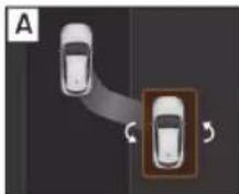


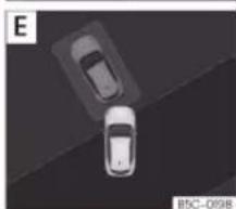
Fig. 179 On the Infotainment system screen.: indication of parking modes.
Park assist has 5 parking modes:
Help with parking and manoeuvring
A Reverse parallel parking.
B Reverse angle parking.
C Forward angle parking.
Reverse parallel parking without driving past first: "Help me".
E Forward parking in a parking bay without driving past first.
Selecting a parking type after passing in front of the space
After activating the Park Assist system and after detecting a parking space, the display on the instrument panel proposes a parking type. The Park Assist system selects the parking type automatically. The selected type is shown on the instrument panel display >> Fig. 178 and on the Infotainment System screen.
- The necessary conditions to park with Park Assist have to be met»»page 275.
-
Press button P in the infotainment system, 📋 > Assistants > Parking > Park assist sys- tem.
-
When the system is connected, the symbol Pon on the Infotainment System screen is highlighted. Additionally, the selected parking type is shown on the instrument panel display. You can change the type of parking on the infotainment system display.
- If there are more spaces available, another space can be selected by clicking on it on the infotainment system display.
- Follow the instructions displayed on the instrument panel while paying attention to traffic and drive the vehicle past the parking space.
Reverse parallel parking without driving past first (type D)
With this type of parking [D], press button P so that the system resolves the parking that has already been started. The system will only switch on if sufficient progress has been made with the manoeuvre (the side sensor must be able to detect the reference vehicle). If it is impossible to successfully complete the manoeuvre that has been started,
the system itself will drive out of the parking space before starting parking in a similar way to type A.
Special case of driving forwards into a type E parking bay without driving past first
- The necessary conditions to park with Park Assist have to be met»» page 275.
- Move forward towards the parking space while paying attention to traffic and stop the vehicle with the front part partially inside the parking space.
- Press button P once in the infotainment system, 📄 > Assistants > Parking > Park assist system.
- When the system is connected, the symbol P on the Infotainment System screen is highlighted. Additionally, the selected parking mode is shown on the instrument panel display without reduced display.
- Release the steering wheel >> △ in Introduction on page 274.
Driving
Parking with the parking assist system


Fig. 180 On the instrument panel display: parallel parking. A Finding a parking space. B Parking position. C Manoeuvring.

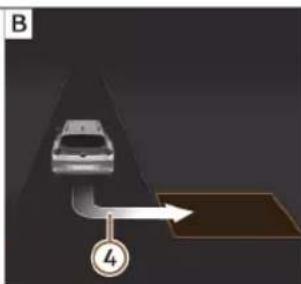

Fig. 181 On the instrument panel display: angle parking. A Finding a parking space. B Parking position. C Manoeuvring.
① Message to move forwards
② Your vehicle
③ Parking space detected
④ Message to park
⑤ Message to press the brake pedal
⑥ Progress bar
The necessary conditions have to be met to park with Park Assist» page 275 and the parking mode must be selected» page 276.
Parking
- Look at the display on the instrument panel to see if the space has been detected as "appropriate" and if the correct position for parking has been reached. Fig. 180 B or>> Fig. 181 B. The space is considered
"appropriate" if the display on the instrument panel shows the message to park ④
- Stop the vehicle and, after a brief pause, engage reverse gear, or press the button in the infotainment system, □ > Assistants > Parking > Park assist system.
- Release the steering wheel >> △ in Introduction on page 274.
Help with parking and manoeuvring
- Please note the following message: Intervention in active direction. Watch your surroundings!. While you keep watch around you, carefully start accelerating up to no more than 7 km/h (4 mph). During the parking manoeuvre, the system only takes charge of the steering. You, as the driver, have to accelerate, engage the clutch if necessary, change gears and brake.
- Reverse until the continuous ParkPilot signal sounds; OR: reverse until the indication to move forward appears on the instrument panel display>> Fig. 180 [c] or >>>Fig. 181 [c]; OR: reverse until the Park Assist finished message appears on the instrument panel display. The progress bar [6] indicates the distance to cover>> page 279.
- Press the brake pedal until the parking assist system completes the steering wheel turns; OR: until the symbol 📋 goes out on the instrument panel screen.
- Select first gear.
- Move forward until the continuous ParkPilot signal sounds; OR: move forward until the reverse indication appears on the instrument panel display. The Park Assist system steers the vehicle forward and back until it centres it in the space >> Fig. 180 c or >> Fig. 181 c.
- For best results, wait at the end of each manoeuvre until the Park Assist system has finished turning the steering wheel. The parking manoeuvre ends when a corre-
sponding message is displayed on the instrument panel and, in some cases, an acoustic signal sounds.
Progress bars
The progress bar
Fig. 180 ⑥ and » Fig. 181 ⑥ on the screen of the instrument panel displays the relative distance to be covered. The greater the distance, the fuller the progress bar. When driving forward, the content of the progress bar decreases upwards, and when reversing, it decreases downwards.
Note
If the manoeuvre is terminated prematurely during parking, the result may not be the best.
Leaving a parking space with the parking assist system (only for parallel parking)

Fig. 182 On the instrument panel display: exit a parallel parking space.
① Your vehicle in reverse gear
② Message giving the proposed manoeuvre to exit the parking space
③ Progress bar to indicate the distance left to cover
Leaving a parking space (parallel parking)
The necessary conditions to exit a parking space with Park Assist have to be met »» page 275.
- Press buttonP in the infotainment system, > Assistants > Parking > Park assist system. When the system is connected, the symbol P on the Infotainment System screen is highlighted.
》
Driving
- Turn on the corresponding turn signal towards the road you will enter when exiting the parking space.
- Engage the reverse gear, or press the button Pout in the infotainment system.
- Release the steering wheel»» in Introduction on page 274. Please note the following message: Automatic steering enabled Pay attention to your surroundings. While you keep watch around you, carefully start accelerating up to no more than 7 km/h (4 mph). When exiting the parking space, the system only takes charge of the steering. You, as the driver, have to accelerate, engage the clutch if necessary, change gears and brake.
- Reverse until the continuous ParkPilot signal sounds; OR: reverse until the instrument panel display shows the forward indication. The progress bar>> Fig. 182 ③ indicates the distance to cover>> page 279.
- Press the brake pedal until the parking assist system completes the steering wheel turns; OR: press the brake pedal until the symbol 📍 goes out on the instrument cluster screen.
-
Move forward until the continuous ParkPilot signal sounds; OR: move forward until the reverse indication appears on the instrument panel display. The Park Assist system steers the vehicle forward and back until it can exit the space.
-
The vehicle can exit the space when a corresponding message is displayed on the instrument panel and, in some cases, an acoustic signal sounds. Take charge of the steering with the turning angle set by the Park Assist system.
- Paying attention to the traffic, exit the parking space.
Automatic operation of the brakes by the parking assist system
Park Assist helps the driver by automatically braking in certain situations.
The driver is always responsible for braking in time»» △.
Automatic braking intervention to avoid exceeding the speed limit
To avoid exceeding the allowed speed of approx. 7 km/h (4 mph) when entering or leaving a parking space, the brakes may activate automatically. After automatically activating the brakes, the manoeuvres to enter or exit a parking space may continue.
The brakes are only automatically activated once for each attempt to enter or exit a parking space. If the speed of approximately 7 km/h (4 mph) is exceeded again, the corresponding operation is halted.
Automatic braking to reduce damages
Depending on certain conditions, the Park Assist system can automatically brake the vehicle when faced with an obstacle, briefly actioning and holding down the brake pedal >> ⚠ Following this the driver must press the brake pedal.
Automatic braking intervention to reduce damage leads to the parking manoeuvre finishing.

WARNING
The automatic braking intervention by Park Assist should never tempt you to take any risk that may compromise safety. The system is not a replacement for driver awareness.
- The Park Assist system is subject to certain limitations inherent to the system. In certain situations, the automatic braking intervention may only work in a limited way or not work at all.
• Always be ready to use the brakes yourself! - The automatic braking intervention will end after approximately 1.5 seconds. Afterwards, brake the vehicle yourself.
Help with parking and manoeuvring
Parking aid parking and manoeuvring (ParkPilot)
Introduction
These assist systems help you when parking and manoeuvring:
- Plus Parking Aid» page 282. It is an assistant that gives a visual and audio warning of obstacles detected in front and behind the vehicle» page 282.
- Rear Parking Aid» page 285. An audio and visual assistant that warns of obstacles located behind the vehicle» page 285.

WARNING
• Always pay attention, by looking directly, to traffic and the area around the vehicle. Assistance systems are not a replacement for driver awareness. Responsibility always lies with the driver.
- The sensors have blind spots in which obstacles and people are not detected. Pay special attention to children and animals.
• Always keep visual control of the surroundings: use the mirrors for additional help.

CAUTION
Parking distance warning system functions can be affected by different factors that can cause damage:
- Under certain circumstances, the system does not detect or display certain objects:
- Chains, trailer draw bars, bars, fences, posts and thin trees.
- Objects that are located above the sensors, such as protrusions in a wall.
- Objects with certain surfaces or structures, such as wire mesh fences or powder snow.
- Certain surfaces of objects and garments do not reflect the ultrasound sensors' signals. The system cannot detect these objects or people wearing such clothes correctly.
- Sensor signals may be affected by external sound sources. This may prevent them from detecting people or objects.
- If the system warns you of the proximity of a low obstacle, please note that after being detected by the system, the obstacle in question may disappear from the measurement sensors as the vehicle moves closer, and the system will no longer warn of its presence. In certain circumstances, objects such as high kerbs that could damage the underside of the vehicle are not detected.
-
If the parking distance warning system is ignored, the vehicle could suffer considerable damage.
-
Damage to the radiator grille, bumper, wheel arch and vehicle underbody can modify the orientation of the sensors. This can affect the parking aid function. Have the function checked by a specialised workshop.
- A number plate or number plate holder with dimensions that exceed the space for the number plate, or a cured or deformed number plate can cause false detections or a loss of visibility for the sensors.

Note
- The display on the Infotainment system screen shows a slight time delay.
- In certain situations, the system can give a warning even though there is no obstacle in the detected area:
– Rough or cobbled surfaces or surfaces with long grass.
– External ultrasound sources, such as other vehicles equipped with ultrasound systems.
- Heavy rain or snow, hail or dense exhaust gases.
- If the number plate is not properly secured to the surface of the bumper.
- Gradient changes.
- In order to guarantee good operation, keep the sensors clean, free of snow and ice, and do not cover them with stickers or other objects.
∴ m = 3/11
Driving
- If you use high-pressure or vapour equipment for cleaning, do not apply it directly, unless you do so very briefly, and always keep a distance of more than 10 cm away.
- Fitting certain accessories to the front of the vehicle, such as a plate holder with advertising, may interfere with the operation of the Park Assist.
• We recommend that you practice parking in an area without traffic. - The volume and tone of the signals and indications can be changed»» page 285.
- Please observe information on towing a trailer» page 285.
Parking System Plus
Description

Fig. 183 Parking aid view on the Infotainment system display.
Parking aid plus assists the driver by giving visual and audio warnings about obstacles detected in front of and behind the vehicle.
The bumpers are fitted with sensors. When an obstacle is detected, it is indicated by audible signals and in the Infotainment system >> Fig. 183.
When moving close to an obstacle, it is possible to know if the obstacle is in front of the vehicle or behind it by choosing different sounds.
The approximate measurement range of the sensors is:
A 1.20 m
B 0.60 m
© 1.60 m
D 0.60 m
As you approach the obstacle, the frequency of the audible signals will increase. The signal will sound continuously at around 0.30 m: Stop!
If the separation is maintained, the warning volume is reduced after about 2.5 seconds.
Parking Aid operation
Manually connecting and disconnecting the parking aid
- Press the function button > Assistants > Parking > Park distance control.
Automatic connection of Parking Aid
- Select reverse gear.
- OR: if you drive forward at a speed of less than 15km / h (9 mph) and you encounter an obstacle, it is detected when it is optically approx. less than 95 cm. away, or acoustically approx. 50 cm. away. If the automatic connection is activated, a reduced display is shown.
- OR: if the vehicle moves back a certain distance (between approx. 10 and 20cm approx depending on whether or not an obstacle is detected)
Automatic disconnection of Parking Aid
- Drive forward at 15 km/h (9 mph) or faster.
• OR: press the parking lock button P.
Temporary suppression of sound in Parking Aid
- Press the function button.
• OR: activate the electronic parking brake.
Help with parking and manoeuvring
Change from reduced view to full view
- Engage the reverse gear if your vehicle is equipped with a reversing camera.
• OR: press the car icon on the reduced view. - OR: if the vehicle moves back a certain distance (between approx. 10 and 20cm approx depending on whether or not an obstacle is detected).
Switch to the reverse assist image (Rear View Camera "RVC")
- Select reverse gear.
- OR: press the RVC button on the Infotainment System screen 1) .
A short confirmation signal will be heard and the button symbol will light up when the system is switched on.
Automatic activation
When the Plus Parking Aid connects automatically, a diagram of the vehicle and the segments will appear on screen. This function will be available unless the user has deactivated it.
It only operates every time the speed is reduced below 15 km/h (9 mph) for the first time.
If disabled using the buttonP% in the info-tainment system (☐ > Assistants > Parking > Park distance control) to be automatically activated again, one of the following actions must be taken:
- Switch off the ignition and switch it on again.
• OR: drive forward at over 15 km/h (9 mph) approx. - OR: activate or deactivate the parking lock button P
- OR: switch the automatic activation on and off in the Infotainment system.
The automatic activation of the parking aid can be switched on and off in the Infotainment system»» page 85»» page 89 :
- Switch the ignition on.
- Press the function button > Assistants > Parking > Park distance control.
- Select Automatic activation. If the box is checked, the function is connected.
If activated automatically, an audible sound warning will only be given when obstacles in
front are at a distance of less than 50 cm. approx.
CAUTION
The automatic connection of the Parking Aid only works when you are driving slowly. If driving style is not adapted to the circumstances, an accident and serious injury or damage may be caused.
Visual indication segments
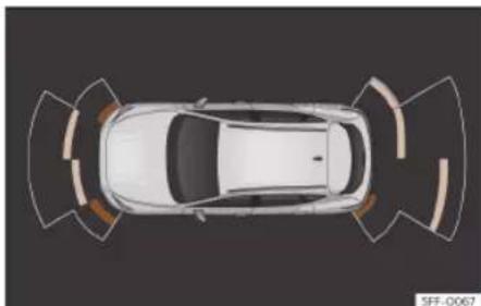
Fig. 184 Parking aid view on the Infotainment system display.
The optical indication of the segments works as follows: »
Driving
- White and segments: the obstacle is more than approx. 30 cm away from the path or in the direction opposite to travel. They are also displayed when the electronic parking brake is activated.
- Yellow segments: the obstacles lie on the vehicle's path and are at a distance of less than approx. 30 cm away.
- Red segments: obstacles are less than approx. 30 cm away.
A wake will indicate the anticipated forward or backward trajectory, depending on the engaged gear.
If an obstacle is located in the vehicle's way, the corresponding audible warning will sound.
When the penultimate segment is displayed, the vehicle has reached the collision zone. In the collision zone, the obstacles are represented in red (including those out of the path). Stop the vehicle! >> △ in Introduction on page 281, >> Ⓞ in Introduction on page 281!
Setting the indications and audio signals
The indications and acoustic signals are set in the Infotainment system: function button
Assistants > Parking > Park distance control:
| Setup | |
| Automatic activation | On/off |
| Front volume | Volume in the front and rear area. |
| Rear volume Volume in the rear area. | |
| Adjust volume | When the parking aid is switched on, the volume of the audio source will be reduced, depending on the selected option. |
Error messages
If a an error or fault message appears on the instrument cluster in Park Assist, there is a fault.
If the fault doesn't disappear before disconnecting the ignition, it will not be indicated next time the parking aid is connected.
If a rear sensor is faulty, only the obstacles in the areas A and B are displayed>> Fig. 183. If a front sensor is faulty, only the obstacles in the areas C and D will be displayed. Symbol A is displayed.
We recommend taking the vehicle to a specialised workshop to have the fault repaired.
Trailer mode
On vehicles with a factory-mounted trailer hook, when the trailer is connected, the rear sensors will not activate when reverse gear is engaged or button P is pressed in the Infotainment system (☐ > Assistants > Parking > Park distance control). Therefore, any objects behind or to the side of the vehicle will not be indicated on the screen and no audio signals will sound.
The screen will only display objects detected at the front, and the vehicle's trajectory will be hidden.
Manoeuvre braking function
The emergency braking function is used to minimise damage in the event of a collision.
Depending on the equipment, if the Parking Aid is active, the braking while manoeuvring function activates emergency braking when it detects an obstacle in the vehicle's path that could cause a collision, driving forwards or in reverse.
The function will not brake if the Parking Aid is activated automatically. For the system to operate, manoeuvring speed must be between 2.5-7 km/h (1.5-4 mph) for the front area and between 1.5-7 km/h (1-4 mph) for the rear.
Help with parking and manoeuvring
Following an intervention, the braking while manoeuvring function will be inactive in the same direction of travel for 5 metres. Once the gear is changed, or the selector lever's position is changed, the function will be active again. The Parking Aid's limitations apply.
The braking while manoeuvring function is set in the Infotainment system: function button ☐ > Assistants > Parking > Park distance control.
Temporary suppression of emergency braking
- When the function is deactivated with the Braking while manoeuvring button that appears on the Parking aid screen of the Infotainment system.
- Whenever any of the car doors, rear lid or bonnet are opened.
Rear parking aid
Description
The rear parking aid is an optical and audible assistant that warns of obstacles located behind the vehicle.
There are sensors integrated in the rear bumper. When they detect an obstacle, you
are alerted by audible and visible warnings on the Infotainment system.
Make particularly sure that the sensors are not covered by adhesives, residues, dirt and the like, as this could affect the system's operation. Cleaning instructions» page 355.
The approximate measurement range of the rear sensors is:
- Side area: 0.60 m
• Central area: 1.60 m
As you approach the obstacle, the frequency of the audible signals will increase. The signal will sound continuously at around 0.30 m: Stop!»» in Introduction on page 281, »» in Introduction on page 281!
If the separation is maintained, the warning volume is reduced after about 2.5 seconds.
Parking Aid connection
- Select reverse gear.
Parking Aid disconnection
- Drive forward at 15 km/h (9 mph) or faster.
- OR: use the selector lever to select N or D, or press the parking lock button P.
Setting the indications and audio signals
The indications and acoustic signals are set in the Infotainment system: function button
Assistants > Parking > Parking assistant.
Settings
Rear volume Volume in the rear area.
| Adjust volume | When the parking aid is switched on, the volume of the audio source will be reduced, depending on the selected option. |
Error messages
If a an error or fault message appears on the instrument panel in Parking assist, there is a fault.
If the fault doesn't disappear before disconnecting the ignition, it will not be indicated next time the parking aid is connected.
We recommend taking the vehicle to a specialised workshop to have the fault repaired.
Towing device
In vehicles equipped with a towing bracket device from the factory, when the trailer is connected, the parking aid will not be activated when reverse gear is engaged.
Driving
Peripheral view system (Top View Camera)
Introduction
Using 4 cameras, the system generates a representation that is shown on the infotainment system display. The cameras are located on the radiator grille, the exterior mirrors and the rear lid.
The functions and representations of the Area View system may vary depending on whether or not the vehicle has ParkPilot.

WARNING
The image from the cameras does not make it possible to calculate the distance to the obstacles (people, vehicles, etc.) precisely, so using them could cause serious accidents and injury.
- The camera lenses augment and distort the visual field and the objects on the screen are seen differently and imprecisely.
- Certain objects may not be shown or may not be shown very clearly, for example, posts or thin rails, due to the screen resolution or if light conditions are insufficient.
- The cameras have blind spots in which obstacles and people are not registered.

WARNING
The smart technology incorporated into the Top View Camera system cannot overcome the limits imposed by the laws of physics and it only works within the limits of the system. The greater convenience provided by the Area View system should never tempt you to take any risk that may compromise safety. If used negligently or involuntarily, it may cause serious accidents and injuries. The system is not a replacement for driver awareness.
- Adapt your speed and driving style to suit visibility, weather, road and traffic conditions.
- Do not be distracted from the traffic by looking at the screen.
- Monitor the area around the vehicle at all times, since the cameras do not capture small children, animals and certain objects in all situations.
- The system will probably be unable to represent all areas clearly.

CAUTION
• The camera images are only two-dimensional. Due to a lack of spatial depth, objects that jut out or holes on the road, for example, are more difficult to detect or may not be seen at all.
- In certain circumstances, the camera does not capture objects such as beams,
fences, posts or thin trees, which could damage the vehicle.
- The system displays the auxiliary lines and boxes regardless of the vehicle's environment, no objects are detected. The driver is responsible for determining that the vehicle will fit in the parking space.
Area View system

Fig. 185 Viewing the top view system: aerial view.
There are four different views to choose from:
A Front camera area
B Right camera area
© Rear camera area
D Left camera area
Help with parking and manoeuvring
Function buttons Fig. 185:
✗ Exit the current display.
Adjust the display: bright, contrast and colour.
Depending on the equipment: connecting and disconnecting the ParkPilot sound.
The aerial view is generated by combining the images from all the cameras 📄 »» Fig. 185. The aerial view can be selected by pressing the vehicle in the area.
Select the corresponding view by pressing the different areas>> Fig. 185 A to D of the aerial view or the reduced aerial view.
Conditions necessary for the use of the Area View system
• The doors and the rear lid must be closed.
- The image must be reliable and clear. For this reason, for example, the camera lens must be clean.
- The area around the vehicle must be clearly and totally visible.
- The area for parking or manoeuvring should be a flat surface.
- The vehicle should not be loaded very heavily at the rear.
- The driver must be used to the system.
- There should be no damage to the vehicle in the camera area. If the position or installation angle of the cameras have been changed, e.g. after a rear-end collision, the system should be checked by a specialised workshop.
Special characteristics
The images on the area view system cameras are only two-dimensional. Due to a lack of spatial depth, it is difficult or impossible to make out on-screen any holes there may be on the ground, objects jutting out from the ground or parts protruding from other vehicles.
Situations in which the objects or other vehicles appear to be further away or closer than they really are:
- On moving from a horizontal plane to a slope.
- On moving from a slope to a horizontal plane.
- If the vehicle is heavily loaded at the rear.
- If the vehicle approaches protruding objects. These objects may be outside the cameras' angle of visibility.
Trailer mode
The Area View system conceals, in the rear camera area, all the auxiliary guiding lines when the factory-fitted towing bracket is
connected electrically to a trailer >> page 291.
Note
To become familiar with the system and its functions, CUPRA recommends that you practice handling the Area View system in an area where there is not too much traffic or in a car park.
Connecting and disconnecting
Connect the reverse assist
- Select reverse gear.
- OR: in the infotainment system select □ > Assistants > Parking > Park distance control.
Disconnect the reverse assist
- Drive forwards at over 15 km/h (9 mph) approximately.
Views of the peripheral vision system (modes)
Depending on the equipment: connecting and disconnecting the ParkPilot sound.
× Exiting the Area View system screen: »
Driving

Adjust the display: bright, contrast and colour.
To select the camera you want to use, press the thumbnail on the left side of the screen. Once activated it will be highlighted in orange. You can switch between views in the menu bar at the bottom of the screen. The selected view will be highlighted in orange.
The red lines are indicate a distance of approx. 40 cm away from the vehicle.
Aerial views (bird's eye view)
Main mode:

The vehicle and its immediate vicinity seen from above are shown. Depending on the equipment, the ParkPilot's path may also be displayed.
Front camera views (front view)

Cross traffic. This visualization helps to monitor traffic to the left, front and right of the vehicle and can be used, for example, when exiting garages or narrow exits.

Angle parking. The area in front of the vehicle is shown. Orientation lines are shown to give guidance.
Side camera views (side view)

Right and left sides. The areas located directly to the side of the vehicle seen
from above are represented in order to navigate possible obstacles more precisely.
Rear camera views (rear view)

Angle parking. The area behind the vehicle is shown. Auxiliary lines are shown to give guidance.

Assistance function for hitching a trailer.
On vehicles with a factory-fitted towing device, this function can be used to move the vehicle close to a tow bar. Auxiliary lines are shown in the infotainment system.
Green lines: distance to the trailer hitch. The distance between the lines is approx. 0.30 m
Yellow line: pre-calculated direction of the trailer hitch depending on how the steering wheel is turned.

Cross traffic. This visualization helps to monitor traffic to the left, front and right of the vehicle and can be used, for example, when exiting garages or narrow exits.
Reverse Assist (Rear View Camera)
Operating and safety warnings

WARNING
- The reverse assist does not make it possible to precisely calculate the distance from obstacles and nor can it overcome the system's own limits, hence its negligent use may cause serious accidents and injuries if used without due care. The driver should be aware of his/her surroundings at all times to ensure safe driving.
• The camera lens expands and distorts the field of view and displays the objects on the screen in a way that is different from reality. Distance perception is also distorted. - Due to the screen resolution or light conditions, some items may be blurry or not displayed at all. Take care with thin posts, fences, railings or trees that might not be seen on the screen and could damage the vehicle.
- The reverse assist has blind spots where it cannot see people or objects. Monitor the vehicle's surrounding area at all times.
- The system is not a replacement for driver awareness. Supervise the parking manoeuvre and the vehicle's surrounding area at all times.
Help with parking and manoeuvring
- Do not be distracted from the traffic by looking at the screen.
• The images are only two-dimensional. Protruding objects or holes in the road, for example, are more difficult to detect or may not be seen at all. -
Vehicle load modifies the representation of the guide lines. The width represented by the lines decreases with vehicle load. Pay special attention to the surroundings when the inside of the vehicle of the luggage compartment are loaded.
• In the following situations, objects or other vehicles appear to be further away or closer than they actually are. Pay special attention: -
If moving from a flat surface to a slope and vice-versa.
- If the vehicle is heavily loaded.
- When the vehicle approaches objects that are not on the ground surface or that protrude from it. These objects may be outside the camera angle when reversing.
Note
- It is important to take great care and pay special attention if the driver is not familiar with the system.
- The reverse assist reference lines disappear when the rear lid is open.
Introduction
A camera installed in the rear lid handle assists the driver with reverse parking or manoeuvring»» page 236.
The camera image is viewed together with orientation lines projected on the Infotainment system screen. Part of the bumper can be seen at the bottom, which can be used by the driver as a reference point.
Reverse assist modes
Depending on the equipment, the following modes are available:
- Angle parking: reverse parking perpendicular to the road.
- Assistance function for hitching a trailer: helps to hitch a trailer.
• Cross traffic: traffic is monitored in a transverse direction.
Connecting and disconnecting
Connect the reverse assist
- Select reverse gear.
- OR: in the infotainment system select > Assistants > Parking > Park distance control.
Disconnect the reverse assist
Drive forward at least 15 km/h (9 mph).
Shown on the display
The system's functions and representations may vary depending on the equipment.
The assistant's image view changes when the factory-fitted tow hitch is electronically connected to a trailer»» page 298.
Reverse assist functions and symbols
When the reverse assist is connected, you can make adjustments using the function buttons. Some adjustments are equipment-dependent.
× Exit the current display
Switch to angle parking»» page 290
Switch to the trailer hitching assistance function
JOL Switch to cross traffic
Adjust the display: brightness, contrast and colour.
Switch to park assist» page 281
Display/hide the parking aid view »
Driving
Guide lines
Green horizontal lines: extension of the vehicle.
Yellow lines: vehicle path depending on the steering angle.
Assistance function for hitching a trailer
On vehicles with a factory-fitted towing device, this function can be used to move the vehicle close to a tow bar.
Auxiliary lines are shown in the infotainment system.
Green lines: distance to the tow hitch. The distance between the lines is approx. 0.30 m.
Yellow line: pre-calculated direction of the trailer hitch, depending on how the steering wheel is turned.
Cross traffic
This visualization helps to monitor traffic behind the vehicle and can be used, for example, when exiting garages or narrow exits.
Requirements
To park with reverse assist, the following requirements must be met:
- Do not exceed a speed of approx. 15 km/h (9 mph).
- Parking space width: vehicle width + 0.15 m (without counting the mirrors).
To display a real image, the following requirements must be met:
• The luggage compartment rear door is closed.
• The surroundings are on a flat surface.
• The vehicle should not be loaded very heavily at the rear.
Parallel parking

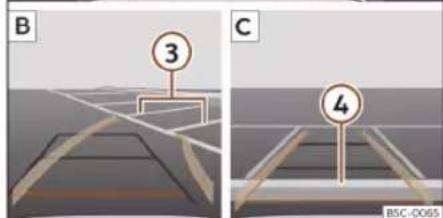
Fig. 186 Display on the Infotainment system screen.: parking with reverse assist.
Key to the Fig. 186:
A Finding a parking space
B Go to the selected parking space
C Centre the vehicle inside the parking space
① Road
② Parking space
③ Lateral boundary of the parking space
④ Rear boundary of the parking space
Parking
- In the infotainment system select > Assistants > Parking > Park distance control before passing in front of the selected parking space.
- With reverse assist connected and in working order, press the function button.
- Place the vehicle in front of the parking space>> Fig. 186 2 A.
- Reverse while turning the steering wheel so that the yellow lines enter the parking space. The green and yellow lines must match the side boundary lines ③ B.
- Stop the vehicle when the red line has reached the rear boundary ④ C.
Towing bracket device
Problems and solutions
The system behaves differently than expected
There can be several causes:
- The camera is dirty»» page 355. In addition to dirt and snow, camera visibility can be reduced by detergent residue or any type of coating.
- The system requirements must be met >> page 290.
• The camera is covered with water. - The factory-fitted towing bracket must not be electrically connected to a trailer » page 298.
- The vehicle has some type of damage in the camera area, e.g. due to a parking impact.
- The field of view of the camera is blocked by an accessory, e.g. a bicycle carrier system.
- Changes have been made to the paint in the camera area, or structural modifications have been made to a component such as the running gear.
Camera with no visibility, fault message, the system disconnects
- Clean the camera or remove possible adhesives or accessories from it»» page 355.
- Check for visible damage.
Possible solution
• Temporarily disconnect the system.
- Check if one of the causes indicated above has occurred.
- Once the source of the problem has been eliminated, the system may be reconnected.
- If the system still behaves unpredictably, have it checked by a specialised workshop.
Towing bracket device
Trailer mode
Introduction
Take into account country-specific regulations about driving with a trailer and the use of a towing bracket.
The vehicle has been developed primarily for carrying people, although it can also be used to tow a trailer if fitted with the corresponding technical equipment. This additional load has an effect on the useful life, fuel consumption and vehicle performance and in some cases can reduce the service intervals.
Driving with a trailer requires more force from the vehicle, and thus more concentration from the driver.
In winter, winter tyres should be fitted on both the vehicle and the trailer.
Maximum vertical load technically permitted on the coupling device
The maximum vertical load technically permitted from the trailer draw bar on the towing bracket's tow ball is 80 kg.
Vehicles with the Start-Stop system
If the vehicle has a factory-fitted towing bracket or one that is retrofitted by CUPRA, »
Driving
the Start-Stop system operates as normal. No special characteristics need to be taken into account.
If the system does not recognise the trailer or the trailer bracket has not been retrofitted by CUPRA, the Start-Stop system must be disconnected by pressing the corresponding button in the lower part of the centre console before driving with the trailer, and it should remain off for the rest of the journey >> △.
Vehicles with driving profile selection
If you are going to be towing a trailer, the use of the Eco driving profile is not recommended. You are advised to select another of the available driving profiles before beginning to drive with a trailer.
Trailer weight/drawbar load
Never exceed the authorised trailer weight. If you do not load the trailer up to the maximum permitted trailer weight, you can then climb correspondingly steeper slopes.
The maximum trailer weights listed are only applicable for altitudes up to 1000 m above sea level. Since higher altitude decreases engine performance and the ability to climb slopes, the tow load decreases proportionally. The weight of the vehicle and trailer combination must be reduced by 10% for every 1000 m of altitude. When possible, operate the trailer with the maximum authorised drawbar load on the ball joint of the towing bracket, but do not exceed the specified limit.
WARNING
Never use the trailer to transport people, since it would put their life in danger and is also prohibited.
WARNING
Undue use of the towing bracket may cause injury and accidents.
- Only use the towing bracket if it is in a perfect state of repair and is properly secured.
- Never modify or repair the towing bracket in any way.
- In order to reduce the danger of injury in the event of rear-end collisions and to avoid injury to pedestrians and cyclists when parking the vehicle, cover or remove the tow hook when you are not using a trailer.
- Never fit a towing bracket "with weight distribution" or "load compensation". The vehicle has not been designed for this type of towing bracket. The towing bracket could fail and the trailer could be released from the vehicle.
WARNING
Driving with a trailer and transporting heavy or large objects can affect driving properties and even cause an accident.
• Always secure the load properly using belts or straps that are suitable and in good condition.
- Adapt your speed and driving style at all times to suit visibility, weather, road and traffic conditions.
- Trailers with a high centre of gravity are more likely to overturn than those with a low one.
- Avoid sudden braking and manoeuvres.
• Take great care when overtaking.
- Reduce speed immediately if you notice that the trailer is swaying, however slightly.
- Never drive at more than 80km / h (50 mph) when towing a trailer (or at more than 100km / h (60 mph) in exceptional circumstances). This also applies in countries where driving at higher speeds is permitted. Take into account the speed limit for vehicles with trailers in the corresponding country, as it could be less than the speed limit for vehicles without a trailer.
- Never attempt to "straighten" the towing vehicle and trailer while accelerating.
WARNING
If the towing bracket has been retrofitted by a non-CUPRA workshop, the Start-Stop
Towing bracket device
system must be disconnected manually whenever driving with a trailer. Otherwise the brake system could be damaged and could consequently cause a serious accident or injury.
• Always disconnect the Start-Stop system manually when using a towing bracket that has not been fitted by a CUPRA workshop.
Note
- Before hitching or unhitching a trailer, always deactivate the anti-theft alarm >> page 95. Otherwise, the tilt sensor could cause the alarm to go off.
- Do not drive with a trailer for the engine's first 1000 km » page 229.
- CUPRA recommends that, if possible, the tow hook be removed or covered when it is not going to be used. In the event of a rear-end collision, the damage to the vehicle could be greater if the tow hook is fitted.
- Some retrofitted towing brackets cover the rear towing eye. In these cases, the towing eye should not be used for tow-starting or for towing other vehicles. For this reason, if the vehicle has been retrofitted with a towing bracket, always keep the tow hook in the vehicle when you remove it.
Technical requirements
Vehicles that are factory-mounted with a towing device meet all the technical and legal requirements for driving with a trailer >> page 298.
If the vehicle is retrofitted with a towing bracket, only a bracket that is authorised for the maximum authorised load of the trailer that is to be towed may be fitted. The towing bracket must be suitable for the vehicle and the trailer and must be properly secured to the vehicle's chassis. Only use a towing bracket that has been authorised by CUPRA for this vehicle. Always check and take into account the towing bracket manufacturer's instructions.
Towing bracket fitted on the bumper
Never fit a towing bracket to the bumper or to the area where the bumper is mounted. The towing bracket should not impair the bumper's function. Do not make modifications or repairs to the exhaust system or the brake system. Make regular checks to ensure that the towing bracket is secure.
Engine cooling system
Driving with a trailer increases the load on the engine and cooling system. The cooling system should have sufficient coolant and be prepared for the additional effort involved in driving with a trailer.
Trailer brakes
If the trailer has its own brake system, please take the relevant legal requirements into account. Never connect the trailer's brake system to the vehicle's brake system.
Tow cable
Always use a cable between the vehicle and the trailer»» page 294.
Trailer tail lights
The trailer's rear lights should comply with the statutory safety regulations»»page 294.
Never connect the trailer's rear lights directly to the vehicle's electric system. If you are not sure that the trailer's electrical connection is correct, have it checked by a specialised workshop. To do so, CUPRA recommends going to a specialised CUPRA dealer or any SEAT dealership.
Exterior mirrors
If you cannot see the area behind the trailer with the exterior mirrors of the towing vehicle, additional mirrors will have to be installed in accordance with the regulations of the country in question. The exterior mirrors should be adjusted before you start driving and must provide a sufficient field of vision at the rear.
Driving

WARNING
If the towing bracket is wrongly fitted or is not the right one, the trailer could become detached from the vehicle and cause serious injury.

CAUTION
- If the rear lights of the trailer are not correctly connected, the vehicle's electronic system may be damaged.
- If the trailer absorbs excessive electric current, the vehicle's electronic system may be damaged.
- Never connect the trailer's electric system directly to the electrical connections of the tail lights or any other power sources. Only use the connections intended for providing electric current to the trailer.
Hitching and connecting a trailer

BSF-1148
Fig. 187 Schematic representation: assignment of the pins of the trailer's electrical socket.
Pin Meaning
| 1 Left turn signal |
| 2 Rear fog light |
| 3 Earth for pins 1, 2, 4, 5, 6, 7 and 8 |
| 4 Right turn signal |
| 5 Rear light, right |
| 6 Brake lights |
| 7 Rear light, left |
| 8 Reverse lights |
| 9 Permanent live |
| 10 Live charge cable |
| 11 Earth for pin 10 |
Pin Meaning
12 Unassigned
13 Earth for pin 9
Power socket for trailer
The vehicle is fitted with a 13-pole power socket for the connection between the trailer and the vehicle. With the engine running, electrical devices on the trailer receive power from the electrical connection (pin 9 and pin 10 of the trailer power socket).
If the system detects that a trailer has been connected, the consumers on the trailer will receive electricity through this connection (pins 9 and 10). Pin 9 has a permanent live.
This powers, for example, the trailer's interior lighting. Electrical devices such as a fridge in a caravan only receive electrical power if the engine is running (through pin 10).
To avoid overloading the electrical system, you cannot connect the ground wires of pin 3, pin 11 or pin 13.
If the trailer has a 7-contact connector, you will need to use an adapter cable. In this case the function corresponding to pin 10 will not be available.
Tow cable
The tow rope must always be securely fixed to the towing vehicle and loose enough so
Towing bracket device
that the vehicle can handle turns smoothly. However, make sure that the cable does not rub on the ground while driving.
Trailer tail lights
Always check the trailer's rear lights to ensure they are working correctly and that they comply with the relevant safety regulations. If you connect the trailer to the factory-mounted system, when you turn on the rear fog lamp, the fog lamp of the towing vehicle will turn off to turn on the trailer fog lamp.
Include in the anti-theft alarm
The trailer is included in the anti-theft system if the following conditions are met:
- If the vehicle is factory-equipped with an anti-theft alarm and towing bracket.
- If the trailer is electrically connected to the towing vehicle through the trailer power socket.
- If the electrical systems of the vehicle and trailer are in perfect condition and have no faults or damage.
- If the vehicle is locked with the key and the anti-theft alarm is activated.
When the vehicle is locked, the alarm is triggered if the electrical connection with the trailer is cut off.
Before hitching or unhitching a trailer, always turn off the anti-theft alarm. Otherwise, the tilt sensor could cause the alarm to go off.
Trailers with LED tail lights
For technical reasons, trailers fitted with LED rear lights cannot be connected to the anti-theft alarm system.
When the vehicle is locked, the alarm does not go off when the electrical connection with the trailer is cut if it has rear lights with light-emitting diodes.
WARNING
If the cables are improperly or incorrectly connected, it may lead to an excessive amount of current supplied to the trailer, which can cause abnormalities in the entire vehicle electronic system, as well as accidents and serious injuries.
- Ensure that any repairs that need to be carried out on the electrical system are carried out by a specialised workshop.
- Never connect the trailer's electric system directly to the electrical connections of the tail lights or any other power sources.
WARNING
Contact between the pins of the trailer power socket can cause short circuits, overloading of the electrical system or fail-
ure of the lighting system, and consequently can cause accidents and serious injuries.
- Never connect the pins of the trailer power socket to each other.
• Make sure any work on bent pins is carried out by a specialised workshop.
CAUTION
Do not leave the trailer connected to the vehicle when parked; place it on its support wheel or its supports. If the vehicle rises or falls due, for example, to a variation of the load or a burst tyre, increased pressure will be placed on the towing bracket and the trailer, and both the vehicle and the trailer can be damaged.
Note
- In case of anomalies in the electrical systems of the vehicle or trailer, as well as in the anti-theft alarm system, have them inspected by a specialised workshop.
- If the trailer accessories consume energy through the power socket to the trailer and the engine is turned off, the battery will discharge.
- If the vehicle battery is running low, the electrical connection with the trailer will be automatically cut.
Driving
Trailer loading
Technically permissible maximum trailer weight and vertical load on the coupling device
The technically permissible maximum trailer weight is the weight that the vehicle can tow >> △. The vertical load on the coupling is exerted vertically from above on the hook of the towing bracket.
The information on the maximum trailer weight and vertical load on the coupling device contained in the type plate of the towing bracket are experimental values only. The correct figures for your specific model, which may be lower than these figures, are given in the vehicle documentation. The information in the vehicle documentation takes precedence at all times.
To promote safety while driving, CUPRA recommends making the most of the maximum vertical load technically permissible on the coupling device»» page 291. An insufficient vertical load has a negative influence on the behaviour of both the vehicle and trailer.
The vertical load increases the weight on the rear axle, reducing the vehicle's carrying capacity.
Gross combination weight of the towing vehicle and trailer
The gross combination weight is the actual weight of the loaded vehicle plus the actual weight of the loaded trailer.
In some countries trailers are classified into distinct categories. CUPRA recommends obtaining information from a specialised workshop regarding which type of trailer is most suitable for your vehicle.
Trailer loading
The weight of the towing vehicle and trailer must be balanced. In order to do this, the load must be as close as possible to the maximum vertical load technically permissible on the coupling point, and it must be evenly distributed between the back and front of the trailer:
- Distribute loads in the trailer so that heavy objects are as near to the axle as possible or above it.
- Secure the trailer load properly.
Tyre pressure
Set the tyre pressure of the trailer tyres in accordance with the trailer manufacturer's recommendations.
When towing a trailer, inflate the tyres of the towing vehicle with the maximum allowable pressure»»page 342.

WARNING
If the maximum permissible axle weight, the maximum load technically permissible on the coupling point, the maximum authorised vehicle weight or the gross combination weight of the towing vehicle and trailer are exceeded, accidents and serious injuries may occur.
- Never exceed the values indicated!
- The actual weight on the front and rear axles must never exceed the maximum permissible axle weight. The weight on the front and rear axles must never exceed the maximum permissible weight.

WARNING
A shift in weight could jeopardize the stability and security of the towing vehicle and trailer, which could lead to accidents and serious injuries.
• Always load the trailer correctly.
• Always secure the load properly using belts or straps that are suitable and in good condition.
Driving with a trailer
Adjusting the headlights
The front part of the vehicle may be raised when the trailer is connected and the light may dazzle the rest of the traffic.
Towing bracket device
Specific features of driving with a trailer
- If your trailer has an overrun brake, brake gently at first and then rapidly. This will prevent the jerking that can be caused by the locking of trailer wheels.
- Due to the gross combination weight of the towing vehicle and trailer, the braking distance increases.
- When going down a slope, engage a lower gear (with a manual gearbox, or use the automatic gearbox's tiptronic mode) to use engine braking. Otherwise, the braking system could overheat and even fail.
- The trailer weight, as well as the gross combination weight of the towing vehicle and trailer, change the centre of gravity and the properties of the vehicle.
- If the towing vehicle is empty and the trailer is loaded, then the load distribution is incorrect. Under these conditions, drive slowly and with extra caution.
Hill starts with a trailer
Depending on the slope of the hill and the combination weight of the towing vehicle and trailer, the vehicle might start rolling backwards slightly when you first start up.
For hill-starting with a trailer, do the following:
- Press and hold the brake pedal.
- Press the Ⓓ button once to disconnect the electronic parking brake» page 266.
- If the vehicle is fitted with a manual transmission, depress the clutch pedal fully.
- Engage first gear or set the gear selector switch to the D/S position.
- Pull out the Ⓐ button and hold it in that position to immobilise the towing vehicle and trailer with the electronic parking brake.
- Release the brake pedal.
- Move off slowly. To do this, release the clutch pedal slowly if your vehicle has a manual gearbox.
- Do not release the (P) button until the engine has sufficient power to start driving.
WARNING
If a trailer is pulled incorrectly, this may lead to loss of control of the vehicle and serious injury.
- Driving with a trailer and transporting heavy or large objects will change the vehicle handling and braking distances.
• Always drive cautiously and carefully. Brake earlier than usual. -
Adapt your speed and driving style at all times to suit visibility, weather, road and traffic conditions. Slow down, especially when driving down hills or slopes.
-
Accelerate with particular care and caution. Avoid sudden braking and manoeuvres.
• Take great care when overtaking. Reduce speed immediately if you notice that the trailer is swaying, however slightly. - Never attempt to "straighten" the towing vehicle and trailer while accelerating.
• Take into account the speed limit for vehicles with a trailer, as it could be lower than for vehicles without a trailer.
Stabilisation of the towing vehicle and trailer combination
The stabilisation of the vehicle and trailer combination is an additional function of the electronic stability control (ESC).
If the system detects that the trailer is weaving, it intervenes to reduce the swaying of the trailer.
Vehicle and trailer combination stabilisation requirements
- The vehicle is factory-equipped with a towing bracket or has been retro-fitted with a compatible towing bracket.
- The ESC and the TCS are switched on. The control lamp or is not lit up on the instrument cluster.
Driving
- The trailer is connected to the towing vehicle through the trailer power socket.
• The vehicle is travelling at over 60 km/h (approx. 37 mph). - The maximum vertical load technically permissible is not being exceeded on the coupling device.
• The trailer has a rigid draw bar. - If the trailer has brakes, it must be equipped with a mechanical overrun brake.
WARNING
The enhanced safety provided by the electric stability control of the vehicle and trailer should not lead you to take any risks that could compromise your safety.
- Adapt your speed and driving style at all times to suit visibility, weather, road and traffic conditions.
- Accelerate with caution when the road is slippery.
- When adjusting any settings, stop accelerating.
WARNING
The electric stability control for the vehicle and trailer may not correctly detect all driving conditions.
- When the ESC is switched off, the stabilisation of the towing vehicle and trailer is also switched off.
- The stability system does not always detect light trailers, so it may not stabilise these correctly.
- When driving on surfaces with poor grip, the trailer can even interfere with the stability system.
- Trailers with a high centre of gravity can tip over without having previously weaved.
- If a trailer is not attached, but a connector is plugged into the power socket (e.g. installation of a bicycle rack with lights), repeated automatic braking may occur in extreme driving conditions.
Electrically unlocking trail-er hook
Description

Fig. 188 On the left side of the luggage compartment: button for unlocking the tow hook.
The towing bracket's hook is located in the bumper. Tow hooks for electrical unlocking cannot be removed.
There should be no person, animal or object in the path of the tow hook >>> ▲.
Unlocking the tow hook and removing it
- Stop the vehicle and connect the electronic parking brake» page 266.
- Switch off the engine.
- Open the rear lid.
Towing bracket device
- Pull the >> Fig. 188 button briefly. The tow hook unlocks electrically and automatically turns outwards. The button's control lamp flashes.
- Finish remove the tow hook by hand until you feel and hear that it has engaged and the control lamp on the button stays on.
- Close the rear lid.
- Hitching and connecting a trailer >> page 294.
Retracting the tow hook
- Stop the vehicle and apply the electronic parking brake.
- Switch off the engine.
- Unhook the trailer and interrupt the electrical connection between it and the vehicle. If you are using an adapter, remove it from the trailer's power socket.
- Open the rear lid.
- Pull the >> Fig. 188 button briefly. The tow hook unlocks electrically.
- Turn the tow hook under the bumper with your hand until you feel and hear that it engages and the control lamp on the button remains on continuously.
- Close the rear lid.
The control lamp →
• If the warning light on the button
Fig. 188 → flashes, this means that the
tow hook has not been attached properly or is damaged >> △
- If the warning lamp >> Fig. 188 → remains on with the rear lid open, the tow hook is correctly in place both when extracted and when covered.
The control light of the lamp switches off approximately 1 minute after closing the read lid.
WARNING
Undue use of the towing bracket may cause injury and accidents.
- Only use the tow hook if it is properly engaged.
• Always ensure that no person, animal or object is to be found in the path of the tow hook. - Never use a tool or instrument while the tow hook is moving.
- Never press the >>Fig. 188 button when there is a trailer hooked to the vehicle or when a carrier system or other accessories are mounted on the tow hook.
- If the tow hook is not attached properly, do not use it. Instead, go to a specialised workshop and have the towing bracket checked.
- If you detect any fault in the electrical system or in the towing bracket, contact a specialised workshop and ask them to check it.
- If the ball has a diameter of less than 49 mm at any one point, do not use the towing bracket under any circumstances.
CAUTION
If you clean the vehicle with high-pressure or steam devices, do not point the jet directly towards the retractable tow hook or the trailer power socket, as this may damage the joints or remove the grease necessary for lubrication.
Note
At extremely low temperatures, the tow hook may be impossible to operate. In this case, place the vehicle in a warmer location (for example, a garage).
Fitting a bicycle carrier on the re-tractable towbar
The maximum allowed weight of the carrier system, including the load, is 75 kg. The carrier system should not protrude more than 700 mm backwards from the spherical head. Only carrier systems on which up to 3 bikes can be mounted are allowed. Heavier bicycles must be mounted as close to the vehicle as possible (tow hook).
Driving

WARNING
The incorrect use of the tow hitch with a bicycle rack mounted on the tow hook can cause accidents and injury.
- Never exceed the maximum weight or the limits indicated above.
- The bicycle rack may not be mounted to the neck of the hook below the ball because, due to the shape of the neck and depending on the rack model, the rack could be incorrectly mounted on the vehicle.
• Always read and take the manufacturer assembly instructions into account.

CAUTION
If the maximum weight and limits indicated above are exceeded, the vehicle may suffer considerable damage.
- Never exceed the values indicated!

Note
CUPRA recommends removing, as far as possible, all removable parts of the bicycles before setting off. These parts include, for example, baskets and saddlebags, child seats or batteries. This improves aerodynamics and the centre of gravity of the rack system.
Retrofitting a towing brack-et
Description

Fig. 189 Limits and attachment points for retrofitting a towing bracket.
CUPRA recommends that towing brackets be retrofitted at a specialised workshop. For example, it may very well be necessary to adjust the cooling system or mount thermal protection plates. To do so, CUPRA recommends going to a specialised CUPRA dealer or any SEAT dealership.
If a towing bracket is retrofitted, the distance specifications should always be kept in mind.
The distance between the centre of the ball head and the road»» Fig. 189 © must never be less than that indicated. This also applies when the vehicle is fully loaded, including the technically permissible maximum vertical load on the coupling device.
Distance measurements (measurements can vary depending on the different chassis combinations)>>> Fig. 189 :
A Mounting points on the vehicle
B 65 mm (minimum)
© 350 mm to 420 mm (fully laden vehicle)
D 1,043 mm
E 414 mm
F 634 mm
G 959 mm

WARNING
If the cables are improperly or incorrectly connected, this may lead to malfunctions in
Towing bracket device
the entire vehicle electronic system, as well as to accidents and serious injuries.
- Never connect the trailer's electric system to the electrical connections of the tail lights or any other unsuitable power sources. Only use suitable connectors to connect the trailer.
- The towing bracket should be retrofitted only at a specialised workshop.
WARNING
If the towing bracket is badly fitted or unsuitable, the trailer may separate from the vehicle while driving. This could cause serious accidents and fatal injuries.
Note
- Only use towing brackets that have been approved by CUPRA for the model in question.
- In some versions, the fitting of a conventional towing hook solution is not recommended. Please consult your Technical Service.
Battery
Battery
High-voltage battery
Safety instructions
Introduction
√ Valid for: hybrid vehicles
WARNING
The vehicle's high-voltage network and the high-voltage battery are hazardous and can cause burns and other injuries, including fatal electric shocks. All high voltage cables are identified by the colour orange.
- It should always be assumed that the high-voltage battery is fully charged and that all of its components are live. This may also be the case when the ignition is switched off.
- Never touch the high-voltage cables, the high-voltage battery or its poles, or allow them to come into contact with jewellery or other metal objects, especially if the high-voltage cables, the high-voltage battery or its poles are damaged.
-
Never take it upon yourself to perform any type of work on the high-voltage network, on the high-voltage cables or the high-voltage battery.
-
Never open or perform maintenance or repairs on components or parts of the high voltage network, or disconnect them from this network.
- Never damage, modify or remove the orange high voltage cables or disconnect them from the high voltage network.
- Never open, modify or remove the cover from the high-voltage battery.
• Work on the high-voltage system, as well as on any systems that may be indirectly influenced by it, should only be carried out by specialized personnel with the corresponding qualifications and training. - Work in the immediate vicinity of high-voltage cables and high-voltage components with tools that are sharp, give off shavings or that have heat sources, such as hot air, thermal bonding or welding work, may only be performed after disconnecting the voltage. The high voltage should only be disconnected by specialized personnel with the corresponding qualifications and training.
- All CUPRA guidelines and standards must be followed when performing any work on the high-voltage system and the high-voltage battery.
- The gases that are emitted or leaked from the high-voltage battery may be toxic or flammable.
- Damage to the vehicle or high voltage battery could cause an immediate or de-
layed leak of toxic gases. The emitted gases could also cause a fire. Do not inhale the gases.
- Never touch the liquids that spill from the high voltage battery and do not touch the emitted gases, particularly if the battery is damaged.
• In the event of a fire, leave the danger area and call the fire department. Inform the fire fighters that the vehicle is fitted with an electric drive system.
• Always inform the fire fighters and the emergency service that the vehicle is fitted with a high-voltage battery.
WARNING
If works are performed on the high-voltage system and on the high-voltage components in an inappropriate manner, this may lead to faults in the operation, accidents and injuries.
• Work on the high-voltage system must only be performed by authorized specialized services with the corresponding permit.
CAUTION
- If the vehicle suffers an accident or collision with an obstacle, the high-voltage battery must be checked by specialized personnel with the corresponding qualifications and training.
High-voltage battery
- If the 12-volt vehicle battery has been disconnected, discharged or replaced, there is a chance that the combustion engine may not initially turn off automatically after moving off. If this situation lasts for several days, contact a qualified specialized workshop. CUPRA recommends visiting a CUPRA partner for this.
High voltage warning lettering
√ Valid for: hybrid vehicles

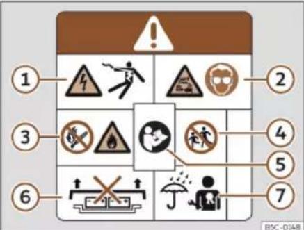
Fig. 191 High-voltage battery warning lettering.
Warning lettering on the vehicle
The following parts of the vehicle can be identified with the depicted warning lettering >> Fig. 190, >> Fig. 191 :
• Covers and lids behind which live high-voltage components are located.
- All the high-voltage components, including the high-voltage battery.
• Under the front bonnet.
The warning lettering>>>Fig. 190 A and B indicate high electrical voltage.
The components of the high voltage system can become very hot and should not be touched» Fig. 190 C.
Fig. 191
① High voltage can cause serious injury or even death. Never touch the battery poles with bare fingers, tools, jewellery or other metal objects.
② The high-voltage battery contains hazardous liquid and solid substances. Emitted gases can cause severe burns and blindness. Suitable eye protection and protective clothing must always be worn when working on the high voltage battery to prevent battery fluid coming into contact with the skin and eyes. If the battery fluid comes into contact with the skin or eyes, the affected areas should be rinsed with clean running water for at least 15 minutes, and then a doctor should be consulted immediately.
③ The high-voltage battery may burn. The high-voltage battery should never be exposed to fire, sparks or naked flame. The high voltage battery must always be handled with care to avoid damage and fluid leakages.
④ The high-voltage battery should always be kept out of the reach of children.
⑤ You will find further information and warnings in the usage instructions and workshop documentation.
⑥ Incorrect handling of the high-voltage battery can cause serious injuries or death. Never disassemble the high voltage battery or remove its cover.
》
Battery
⑦ Incorrect handling of the high-voltage battery can cause serious injuries or death. Maintenance work on the high-voltage battery must only be performed by specialized personnel with the corresponding qualifications and training. Never modify the high-voltage battery. When the high-voltage battery is open, ensure it does not come into contact with water or other liquids. Liquids may cause short circuits, electrical shocks and burns.
Conservation of the high-voltage battery
Conservation instructions
√ Valid for: hybrid vehicles
Reliability and capacity of the high-voltage battery
In principle, lithium ion batteries are subject to ageing and wear and tear throughout their useful life due to their physical and chemical characteristics. Correct use of the high-voltage battery makes a considerable contribution to keeping it in a reliable state in the long term and to achieving high useful capacity and range. Therefore, it is extremely important to respect the following conservation instructions for the high voltage battery. These
maintenance instructions are essential for maintaining the vehicle's value over time.
Please also observe the applicable CUPRA warranty conditions for the high-voltage battery.
Conservation instructions
CUPRA recommends the following conservation instructions:
- Only charge the high-voltage battery when a low charge level is displayed on the instrument cluster, or when the electric range is low»» page 77.
- Do not directly charge the high-voltage battery after only a short drive in full electric mode.
- As much as possible avoid fully discharging the high-voltage battery, such as by leaving the vehicle parked for a prolonged time with a low load level. The charge level must not drop below 20% for long periods of time
>>> !
- When the high-voltage battery has been fully charged, start driving immediately if possible.
Vehicle parking times
- If there is a frost, do not park the vehicle for several hours with a charge level of lower than 40% >>
- If you plan to leave your vehicle stationary for prolonged periods of time, park with a charge level of at least 30% . This situation occurs, for example, when you leave your vehicle at the airport before a trip.
- Do not expose the vehicle to outside temperatures below -30°C or above 60°C for over 24 hours.
CAUTION
The high-voltage battery must not be used as a stationary power supply. This can cause irreversible damage to the high-voltage battery.
CAUTION
If the vehicle is parked for a long time with the high-voltage battery discharged, it may no longer be possible to charge the battery or start the vehicle. Irreversible damage could be caused to the high voltage battery in the long term.
- Charge the high-voltage battery at regular intervals.
High-voltage battery
Charging settings in the infotainment system
Battery Manager Menu
√ Valid for: hybrid vehicles
The Battery Manager allows you to set or select departure times for the programmed charging of the high-voltage battery and for the vehicle's electric heating and air conditioning.
Open the Battery Manager menu
- Switch the ignition on.
- Switch on the infotainment system.
- Select Battery Manager from the main menu.
It is possible to change the settings for immediate charging (the next charging process).
- Reduce the charging current, e.g. when other major consumers are operating on a single line of the electrical installation at the same time. Charging power is reduced and charging time is extended.
- Set the desired temperature for the stationary air conditioning»» page 159.
Departure time settings menu
Programmed charging (departure times) can be set»» page 305.
- Specify the amount of time for which you want the high-voltage battery to charge and the air conditioning to be switched on inside the vehicle.
Extended stationary air conditioning menu
- Set the desired temperature for the stationary air conditioning»» page 159.
- Warm the seats and windscreen for departure: select the seats in the Infotainment system or switch on windscreen heating. The active functions will be switched on during stationary air conditioning (either due to an immediate start or departure scheduling) if considered necessary by the air conditioning (cold conditions).
The air conditioning works both when the vehicle is connected to the grid and disconnected. If you want to use the high-voltage battery as the power supply, change the setting in the Settings menu.
Charging settings menu
It is possible to configure the general settings for the charging process.
- Lower battery charge limit (minimum desired charge level of the high voltage battery): a minimum range can be ensured with this function. The vehicle charges directly once it has been connected to a charging station or electrical socket. The function is available if a departure time has been activated»» page 305.
• Air conditioning using the high-voltage battery: If the vehicle is not plugged in to an external network and this option is enabled, the electric range of the vehicle can be significantly reduced!
Departure time settings
√ Valid for: hybrid vehicles
With programmed charging, the battery charge can be programmed and delayed so that the desired battery level is reached at a certain time when the vehicle is connected to the charging socket.
Viewing the departure times
- Select Battery Manager from the Infotainment main menu.
- Select ④ to open the overview of departure times.
Battery
Departure time settings
To set the desired departure time, touch the corresponding function button or check the box √.
- Departure times: Time, day of the week or set a single or weekly departure time.
- Air conditioning: the vehicle interior is heated or cooled at the departure time »» page 159.
- Trough or night-time tariff: a preferred period of time for charging can be set.
Activating the departure time
Activate the departure time by checking the box in the departure times overview.
Displays
Charging activated at a departure time.
Air conditioning switched on at a departure time.
The departure time is used regularly.
Charging the high-voltage battery
Introduction
√ Valid for: hybrid vehicles
Check that the driving mode is deactivated and that the charging cable and infrastructure are in perfect condition.
Charging modes
Your vehicle has the following possible charging modes:
- Fixed AC (alternating current) charging station or Wallbox, also known as Mode 3 charging»» page 308 : The vehicle can be charged at maximum power at these stations, e.g. at a public charging station or home Wallbox.
- Portable charging station or ICCB (In-Cable Control Box) cable, also known as Mode 2 charging or cable» page 308 : The Mode 2 cable is included as standard and is connected to a conventional household electrical socket, meaning that the maximum power will be limited »» △. You must plan for a longer charging time, e.g. overnight.
The home's electrical installation must be verified and in perfect condition.
Direct current (DC) or Mode 4 charging is not compatible with this vehicle.
Differential protection
The vehicle is fitted with a direct current leakage (DC leakage) protection device. This prevents any DC leaks that may occur during charging from flowing into the home's electrical installation through the charging cable.
WARNING
Charging the battery improperly, failing to observe generally applicable safety measures, using unsuitable or damaged electricity sockets and charging cables, charging from an unsuitable electrical installation or incorrectly handling the high-voltage battery can cause short circuits, electrical discharges, explosions, fires, burns, serious injury and even death.
• Always follow the steps in the order in which they are shown to avoid the risk of an electrical discharge and serious injury caused by the residual energy present in the charging accumulator. Never pull on the mains connector during charging.
- Only charge the vehicle from correctly installed power sockets that have been tested and are undamaged, and from electrical installations in a perfect state of repair. Get specialized personnel to periodically inspect the power sockets and the electrical installation.
High-voltage battery
- Only plug in the charging cable to an electrical socket that is protected from water, humidity and other liquids.
- Never charge the vehicle in potentially explosive atmospheres. The components of the charging cable can cause sparks and, therefore, may ignite flammable or explosive vapours.
- Never use damaged charging connectors or cables. Before each use, check that the connector and charging cable are not damaged.
- Never use the charging cable with an extension lead, rolled cable, power strip or adapter, e.g. adapter for other countries or timer.
• Always protect the connectors to prevent water, moisture and other liquids from directly getting inside. - For safety reasons, no other work should be performed on the vehicle while it is charging.
• Always end the charging process before unplugging the mains connector. Otherwise the charging cable and the electrical installation may also be damaged. - Never charge several vehicles simultaneously from electrical sockets of the same safety circuit. Use a different safety circuit to charge additional vehicles. Always check the maximum current or power of the safety circuit that is used. If necessary, seek ad-
vice from qualified electrical installation professionals.
- Only use the charging cables supplied with the vehicle or the charging station cable. If the cable needs to be replaced, it is recommended to exclusively use CUPRA charging cables.
- Never make changes or repairs to electrical components, particularly the high voltage system.
• Always unplug the charging cable before starting the vehicle. Place the protective caps and close the cover of the battery charging socket.
Note
• The high-voltage battery can only be charged at charging stations that meet the following requirements and regulations:
- IEC 61851 and IEC 62196 (type 2 connector).
- Very low or very high temperatures can noticeably reduce the high voltage battery's charging power.
• To avoid possible compatibility problems with charging infrastructures, CUPRA recommends the use of cables and home charging stations recommended by the Volkswagen Group. - For charging with alternating current, CUPRA recommends charging the high-voltage battery at maximum charging pow-
er from a fixed charging station or Wallbox. This achieves greater efficiency when compared to charging from an electrical socket.
- Check the technical information about your vehicle's charging capacity. You can get more information a specialised CUPRA dealer or any SEAT dealership.
Identification of compatible charging infrastructure
√ Valid for: hybrid vehicles

BFJ-0228
Fig. 192 Identification of alternating current (AC) and type 2 connector.
C

D

BFJ-0229
Fig. 193 Identification of direct current (DC) and the vehicle's CCS connector
Battery
Compatibility between vehicles and charging infrastructure
The following indicators according to DIN EN 17186 report whether the infrastructure's charging connectors are suitable for the vehicle >>> △.
Indicators>>> Fig. 192
A In the vehicle
B At the charging station
Indicators>>> Fig. 193
C Voltage up to 500 volts
D Voltage of up to 1000 volts.
The indicators are located on the vehicle's charging socket, on components of the local charging infrastructure (charging station, socket) and on the charging cable. The indicators refer to standardized charging systems as per the DIN EN 62196 standard.
WARNING
Charging the vehicle at unverified electrical installations can cause serious injury and damage.
- If there is no indicator or if the charging infrastructure is unknown, an electrical installation expert should be consulted first.
AC charging
√ Valid for: hybrid vehicles

Fig. 194 Behind the battery charging cover on the front left-hand side: Charging socket
>>> Fig. 194
① charging socket
② Charging process display
The battery charger installed in the vehicle converts alternating current from the public supply into direct current.
AC Charging Station, Wallbox or mode 2 cable: The vehicle's high-voltage battery can be charged using alternating current (AC) through the corresponding charging socket ①.
Connecting the charging cable
- Firstly, connect the charging cable to the electrical socket, charging station or Wall-box. Next, fully unwind it.
- Charging cable for power sockets: The protection device performs a self-test >> page 313.
- With the vehicle unlocked, the battery charging cover opens when it is pressed >> Fig. 194.
- Plug the charging connector into the charging socket. Check that the charging connector is fully plugged in.
The connector locks automatically.
The LED (charging process display) lamp on the charging connector lights up ② The indicator lamp lights up on the instrument cluster display ②.
Automatic start of the charging process
If programmed charging is not activated, the charging process starts immediately >> page 305. The external charging infrastructure must be active.
During the charging
The charging process display on the charging socket flashes green ②. The indicator lamp ➕ flashes green on the instrument cluster.
High-voltage battery
Interrupt the charging process
The charging process can be interrupted:
- Unlock the vehicle.
- Press the function button to end the charging process. The charging process display on the charging socket lights up in white ②.
- Unlock the vehicle to unlock the charging connector.
To restart the charging process just press the function button to start the charging process.
After charging
When the high-voltage battery is fully charged, the charging process display on the charging socket lights up green.
- Unlock the vehicle.
- Unplug the charging connector from the charging socket within 30 seconds.
- Disconnect the charging cable from the power supply and replace the protective cap.
- Close the charging cover and make sure you hear it click into place.
First charge and charging after a long time
If the high-voltage battery is new or has not been charged for a long time, the maximum charge level of the battery can only be
reached after several charging processes. This is for technical reasons and is not a vehicle malfunction.
If the vehicle is not used for a long period of time, the high-voltage battery must be charged at least once every four months.
Note
If you leave the charging cable connected after charging, the vehicle's electrical consumers will not drain the high-voltage battery.
Charging process display
√ Valid for: hybrid vehicles

Fig. 195 Behind the cover of the battery charging socket: charging process display

Fig. 196 On the inside of the cover of the battery charging socket: sticker with information on the charging process display.
An LED light on the charging socket >> Fig. 195 (arrow) shows the status of the charging process.
A sticker on the battery charging cover provides information on the meaning of the LEDs»» Fig. 196.
charging process displays:
Green LED>>>Fig. 196 :
① Always on: Charge completed successfully.
② Turn signals: The high-voltage battery is charging.
Battery
③ Short flashes: Programmed charging is active. The charging process has not yet started.
Yellow LED>>> Fig. 196 :
④ Turn signals: The parking lock P has not been enabled.
⑤ Always on: No electrical network has been detected. Arrange an inspection of the power supply and network. Seek professional assistance.
Red LED >>Fig. 196 :
⑥ Turn signals: Error in the charging system. The charging process cannot start or has paused.
Always on: The charging connector has not been locked. Unplug the charging connector and plug it back in to the charging socket, making sure it is properly inserted. If the problem persists, check the compatibility of the cable or ask a professional for help.
Charging socket lighting
In the dark, the charging socket's side lighting (white LED) can facilitate orientation in the vehicle:
Ignition
• The vehicle has been unlocked.
- OR: The charging connector has been unplugged from the charging socket.
Off
• After unlocking or locking the vehicle, the lighting switches off automatically after a while.
Note
If the charging process display permanently indicates an error in the power supply or vehicle's charging system, you should seek professional assistance.
Troubleshooting
√ Valid for: hybrid vehicles
Error in the electric drive system
The warning lamp lights up red. 📋 You must park the vehicle in a safe place.
The corresponding error message is displayed on the instrument cluster display.
Fault in the electric drive system. The high voltage components may be damaged»» △.
- Park the vehicle outdoors as soon as it is possible and safe to do so.
- Switch off the drive system.
- Seek professional assistance.
The charging process is not possible or has been paused
An error may be displayed on the instrument cluster display or on the charging socket's charging process display.
You can try the following to solve the problem before seeking professional assistance:
- Unlocking the charging connector and plug the charging cable in again.
- OR: Make sure that the charging settings are as desired: "immediate" or "programmed".
- OR: Check if the charging connector is properly plugged in.
- OR: Check if a fault is displayed on the charging station or, depending on the features, on the displays of the mode 2 charging cable.
If the fault cannot be rectified, seek professional assistance directly.
WARNING
High-voltage components, including the battery and high-voltage cables, may be live and damaged. The high voltage system voltage is dangerous and can cause burns, other injuries and fatal electric shocks.
- Do not touch the high voltage components!
High-voltage battery
Emergency release of the charging connector
√ Valid for: hybrid vehicles

Fig. 197 Between the left wing panel and the engine bonnet hinge: Charging connector manual release mechanism puller.
Unlocking the charging connector
Prerequisites:
- The charging connector is plugged in correctly»» page 308.
• The vehicle is unlocked. - The charging process has ended or has paused >> page 306.
The manual release mechanism must be used if these prerequisites are met and it is still impossible to unplug the charging connector.
Manual release of the charging connector The puller for the manual release mechanism is at the front left of the vehicle interior, above the charging socket»»Fig. 197.
- Disconnect the power supply at the charging station or electrical socket.
- Open the bonnet and make sure it is held in place with the prop.
- Pull the puller >>>Fig. 197 .
- Immediately unplug the charging connector.
Note
- The manual release mechanism of the charging connector should only be used in the event of a failure.
- After using the charging connector's manual release mechanism, the charging socket must be inspected immediately by a professional.
Charging cable
Introduction
√ Valid for: hybrid vehicles
The type of charging cable supplied with the vehicle depends on the delivery volume and the specific technical specifications of each country, e.g. charging connector connections for power sockets.
CUPRA recommends exclusively using the supplied charging cable.
Notes on the charging cable
- Handle with care.
- Unroll and roll fully.
- Do not twist or bend it over sharp edges.
- Do not crush it or drive the vehicle over it.
• Always unplug it by pulling on the connector. - Children should not use the charging cable.
- Keep animals away from the charging cable.
• After use, store it safely and without twisting it.
Notes on charging connectors and the charging cable protection device
- Do not touch the charging connector's contacts.
- Protect from strong sunlight (outside temperatures no higher than 50°C or 122°F ).
- Do not drop them.
- Protect from immersion in fluids such as rain water.
- Fit the protective caps after each use.
Battery
Cleaning the charging cable
- Clean the surface of the charging cable with a dry or slightly damp cloth >> △, >> ⚠.
WARNING
Items that are not secured, or incorrectly secured can cause serious injury during sudden manoeuvres or braking, or in the event of an accident.
- Store the charging cable securely in the luggage compartment.
- Use the organizer/protective cover provided with the cable for this purpose.
WARNING
Using a charging cable that has been damaged or tampered with can cause serious injury and fatal electric shocks.
- Before each use check that the connectors and the charging cable are undamaged, e.g. check for cracks.
- Never use a charging cable that is damaged or has been tampered with.
- If the charging cable does not work correct, get a specialised CUPRA dealer or any SEAT dealership to look at it.
WARNING
The charging cable for electrical sockets must always be connected directly to an electrical socket. Failure to do so could re-
sult in fire damage and damage to the charging cable or home electrical installation.
- Never connect the charging cable to an extension lead, cable reel, power strip or adapter or timer.
WARNING
The high voltage system voltage is dangerous and can cause burns, other injuries and fatal electric shocks.
- Only clean the charging cable when it is unplugged.
CAUTION
The charging cable, as portable electrical equipment, may have to be checked periodically. This requires a test adapter.
CAUTION
The charging cable can be damaged if not cleaned properly.
- Only water should be used for this purpose, and never additional cleaning products.
• Water should be prevented from getting into the contacts.
For the sake of the environment
Charging cables must be disposed of in an environmentally friendly way and should not be thrown in the household waste.
Note
The maximum charging capacity of the safety circuit that is used must be observed. If the charging cable is planned into an electrical socket on the same circuit as other consumers, the circuit's fuses may trip.
Charging cable for alternating current (AC) charging stations
√ Valid for: hybrid vehicles
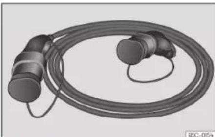
Fig. 198 Charging cable for alternating current (AC) charging stations.
High-voltage battery
The maximum charging current is 16 or 32 amps, depending on the vehicle's features and the charging cable that is supplied »» △.

WARNING
Charging the high-voltage battery with an inappropriate charging cable could cause short circuits, serious injuries and fatal electrical shocks.

WARNING
The charging cable should not be used as an extension lead. The charging process could be affected.

CAUTION
Follow the manufacturer's instructions and indications when using the charging station.

Note
Charging with a 16 A charging cable is not possible in some charging stations that support 32 A. This depends on the features of the charging station.
- Before charging the vehicle, find out about the available charging technology.
Charging cable for power sockets
√ Valid for: hybrid vehicles

Fig. 199 Charging cable for electrical sockets

Fig. 200 On the charging cable for power sockets: Indicator lamps on the protection device.
Fig. 200:
① Indicator lamp of the connector and the power supply.
② Control lamp of the protection device
③ Control lamp of the vehicle
④ Failure warning lamp
Charging cable information
Before using the charging cable, also follow the instructions displayed on it and on the rear of the protective device.
Protection device
The electronic protection device >> Fig. 200 ensures that the charging connector does not receive current until it is plugged in to the vehicle's charging connector.
Self-check
When the charging cable is plugged into the electrical socket, the protective device automatically performs a self-test. During this check, all warning and indicator lamps turn on briefly and go out one after the other. Upon completion, the operational status at that time is displayed.
Operating displays
One or more indicator lamps>>> Fig. 200 ① ② or ③ light up green.
Battery
Display>>> Fig. 200 Meaning
| 1on | The charging cable is plug- ged into the mains but has not been connected to the vehicle. |
| 1,2on,3flashes slowlya1 | The high-voltage battery is charging. |
| 1,2and3on | The charging process is complete. The high-voltage battery has charged. |
a) The available supply voltage depends on each country.
Set the charging current
The charging cable limits the charging current according to the available power supply.
If the local mains supply does not allow charging at the maximum charging current, the charging current can be reduced, depending on the charging setting features in the infotainment system»» page 305.
Temperature control
The charging cable temperature control switches on when the charging cable overheats, such as when it has been stored in a luggage compartment exposed to high temperatures or strong sunlight.
When the charging process is interrupted, the status indicator that is lit up at the time switches off and one of the indicator lamps
starts slowly flashing green. Warning lamp ④ starts slowly flashing red.
- Unplug the charging cable and let it cool down.
- If the error occurs again, seek professional assistance.
If charging continues with a lower charging current, warning lamp ④ lights up in red in addition to the status indicator. The charging cable must be allowed to cool down for a while. The charging current automatically increases again.
Fault display
If the red warning light ④ flashes or turns on without one of the indicator lamps
Fig. 200 ①, ② or ③ also turning on continuously on the status indicator, there is a fault.
| Display >> Fig. 200 Meaning | |
| 1 flashes, 4 on or flashing | Failure in the power supply. |
| 2 flashes, 4 on or flashing | Failure in the protection device. |
| 3 flashes, 4 on or flashing | Failure in the vehicle. |
The charging process pauses or is cancelled.
- Check the instructions located on the back of the protective devices.
- Seek professional assistance if the fault persists.
Note
If there is any other mains connection during the charging process, or if the vehicle is right next to the high voltage cables, charging from an electrical socket is not possible in some cases. Additional mains connections:
- Connecting a 12 volt battery charger.
- Contact with a work tool connect to the mains, such as a vehicle lift.
Checking and refilling levels
Practical tips
Checking and refilling levels
Refuelling
Purging the fuel tank
√ Valid for: hybrid vehicles.
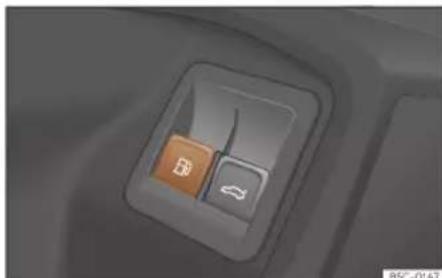
Fig. 201 Driver's door: tank flap release.
Before refuelling the fuel system must be depressurised >> △ in Refuelling on page 316. To do this, press the 📄 button on the driver's door.
An audible sound will be played and a warning will be displayed on the instrument cluster display.
After a few seconds the fuel tank flap will unlock and remain unlocked for a few minutes. If you have not refuelled after this time, you must press the 📄 button again before refuelling.
Avoid touching the fuel tank flap lock button >> Fig. 202 (arrow). The system will interpret that you have finished and cannot continue refuelling. Press the 📄 button on the driver's door again to continue.
Refuelling
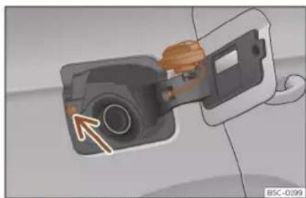
Fig. 202 Fuel tank flap with tank cap attached.
The fuel tank flap is on the rear right of the vehicle.
The flap that covers the tank cap is unlocked and locked automatically using the central locking.
- Hybrid vehicles: Use the 📄 button on the driver's door to release the tank flap.
- Open the fuel tank flap by pressing on the retainer zone.
• Unscrew the cap by turning it to the left. - Place it in the space on the hinge of the open flap>>Fig. 202.
- Start refuelling. The tank is full as soon as the pump's automatic nozzle cuts off the fuel supply. Do not try to put in more fuel after the nozzle cuts out, as this will fill the expansion chamber in the fuel tank.
- Unscrew the cap by turning it to the right as far as it will go.
- Close the lid.
The correct fuel grade for your vehicle is given on a sticker on the inside of the fuel tank flap. Further notes on fuel can be found at >> page 317.
The capacity of your vehicle's fuel tank is given in»» page 367.
Hybrid vehicles
Every 6 months it is necessary to run on petrol until the control lamp switches off, and then the tank must be refilled. This is necessary to ensure that the system works properly, as well as the fuel quality required for driving with petrol.
》
Practical tips

WARNING
Fuel is highly flammable and can cause serious burns and other injuries.
- When refuelling, turn off the engine and turn off the ignition for safety reasons.
- The fuel system of PHEV models is pressurized to prevent petrol vapours from escaping into the atmosphere.
- Do not smoke when filling the fuel tank or a canister. Naked flames are forbidden in the vicinity due to the risk of explosion.
- Observe legislation governing the use, storage and carrying of a spare fuel canister in the vehicle.
- For safety reasons we do not recommend carrying a spare fuel canister in the vehicle. In an accident the canister could be damaged and could leak.
-
If, in exceptional circumstances, you have to carry a spare fuel canister, please observe the following points:
-
Never fill fuel into the spare fuel canister if it is inside or on top of the vehicle. This could cause an explosion. Always place the canister on the ground to fill it.
- Insert the filling nozzle as far as possible into the spare fuel canister.
- If the spare fuel canister is made of metal, the filling nozzle must be in con-
tact with the canister during filling. This helps prevent an electrostatic charge building up.
- Never spill fuel in the vehicle or in the luggage compartment. Fuel vapour is explosive. Risk of fatal accident!

CAUTION
- If any fuel is spilt onto the vehicle, it should be removed immediately. It could otherwise damage the paintwork.
- Never run the tank completely dry. The catalytic converter can be damaged.
- When filling the fuel tank after having run it completely dry on a vehicle with a diesel engine, the ignition must be switched on for at least 30 seconds before starting the engine. When you then start the engine it may take longer than normal (up to one minute) to start firing.

For the sake of the environment
Do not overfill the fuel tank, it may cause the fuel to overflow if it becomes warm.

Note
There is no emergency mechanism for the manual release of the fuel tank flap. If nec-
essary, request assistance from specialised personnel.

Note
Diesel vehicles are fitted with a protective device that prevents the insertion of the wrong fuel hose 1) . It is only possible to refuel with Diesel nozzles.
- If the pump nozzle is worn, damaged, or if it is very small, it is possible that it will not be able to open the protective device. Before trying to insert the pump nozzle by turning it, try a different pump or request specialist help.
- If you fill the tank from a reserve fuel canister, the protective device will not open. One way to resolve this is to pour the fuel in very slowly.
Checking and refilling levels
Fuel types
Identification of fuels 1)
![graph TD A["①"] --> B["E5"] C["②"] --> D["B7"] E["③"] --> F["XTL"] G["④"] --> H["CNG"]](/content/2026/07/1418883/images/88b388310e39c0fa86c06d72208b0ef367bd6fcdc041a232cea7bcb9cae8b6e5.jpg)
Fig. 203 Identification of fuels according to European Union (EU) Directive 2014/94/
Fuels are identified by different symbols on the pump and on your vehicle's tank flap. The identification serves to prevent confusion when choosing the fuel.
① Petrol with ethanol ("E" stands for Ethanol). The number indicates the percentage of ethanol in the petrol. "E5" means, for example, an ethanol ratio of 5% max.
② Diesel according to EN590 standard. The number indicates the maximum percentage of Biodiesel in the fuel. "B7" means a maximum of 7% Biodiesel.
③ Synthetic diesel according to EN15940 standard.
④ Natural gas: "CNG" means Compressed Natural Gas.
Type of petrol
The correct grade of petrol is listed inside the fuel tank flap.
The vehicle is equipped with a catalytic converter and must only be run on unleaded petrol. The petrol must comply with the standard EN 228 and be sulphur-free. Fuels with a 10% ethanol ratio can be refuelled (E10) 2 . The types of petrol are differentiated by using the octane numbers (RON) or via the anti-knock index (AKI).
Super unleaded petrol 95 octane petrol or normal 91 octane petrol at least
We recommend refuelling with super 95 octane petrol (91 AKI). If not available, normal
91 octane petrol (87 AKI) (with a slight power loss) may be used.
Super unleaded petrol, 95 octanes at least
You should use super 95 octane petrol (91 AKI) at least.
If super is not available, if necessary, use normal 91 octane petrol (87 AKI). In this case only use moderate engine speeds and a light throttle. Refuel with super as soon as possible.
Unleaded super plus 98 octane petrol or super 95 octane petrol at least
We recommend refuelling with super plus 98 octane petrol (93 AKI). If not available: super 95 octane petrol (91 AKI) (with a slight power loss).
If super is not available, if necessary, use normal 91 octane petrol (87 AKI). In this case only use moderate engine speeds and a light throttle. Refuel with super as soon as possible.
Practical tips
CAUTION
- Fuels high percentage of ethanol, e.g. E30 - E100 button must not be used. The fuel system would be damaged.
- A single refuelling with leaded fuel or other metal additives entails a permanent deterioration of the effectiveness of the catalytic converter.
- Only use fuel additives that have been approved by SEAT. The products that contain substances to increase the octane rating or decrease knocking may contain metal additives that damage the engine and catalytic converter. This type of products must not be used.
- Do not use fuels shown in the pump as containing metals. LRP (lead replacement petrol) fuels contain high concentrations of metal additives. Risk of engine damage!
• High engine speed and full throttle can damage the engine when using petrol with an octane rating lower than the correct grade for the engine.
Note
- Fuel with an octane rating higher than the one required by the engine can be used.
• In countries in which there is no sulphur-free fuel, it is also allowed to use low sulphur content fuel.
Diesel
√ Valid for: vehicles with diesel engines
Please note the information on the inside of the fuel tank flap.
The diesel can thicken at very low temperatures, thus affecting the start or operation of the engine. Ask your service station attendant if their diesel is suitable for winter use.
Water in the fuel filter 1)
If your vehicle has a diesel engine and is equipped with a fuel filter with a water separator, the instrument panel may display the following warning: "Water in the fuel filter. If this is the case, take the vehicle to a specialised workshop so that they can drain the fuel filter.
CAUTION
- Never use of FAME (biodiesel that does not meet the EN590 standard), petrol, heating oil, other fuels or thinning agents
as they can cause severely damage the fuel system and the engine.
- If the wrong fuel has been filled, do not start the engine under any circumstances. Risk of damaging the fuel system and the engine! Seek professional assistance.
AdBlue®
Information about AdBlue®
AdBlue® consumption depends on your personal driving style, the temperature of the system and the outdoor temperature when the vehicle is used.
AdBlue® freezes at temperatures of -11°C (+13°F). The system has heating elements that guarantee its operation even at low temperatures.
The AdBlue ® tank has a capacity of approx. 11 litres.
When the range is less than 2400 km the instrument cluster screen displays a message requesting an AdBlue® refill.
If this message is ignored, the yellow warning lamp will come on when the remaining range is less than 1000 km. The
Checking and refilling levels
indication that in XXX km it will no longer be possible to restart the engine will appear on the instrument panel display.
If the yellow indicator lamp is ignored, when remaining range of 0 km is displayed, it will no longer be possible to restart the engine. The red warning lamp will light up ♂.
AdBlue® is a registered trademark of the German Association of the Automotive Industry (VDA) and is also known as AUS32 or DEF (Diesel Exhaust Fluid).

CAUTION
Overfilling with AdBlue® can cause damage to the tank system.
Control and warning lamps

It lights up red
The engine cannot be restarted! The AdBlue level is too low.
Stop the vehicle in a suitable, safe and flat area then top up with the minimum required quantity of AdBlue >>page 319.

and
They light up red
The engine cannot be restarted! Fault in the AdBlue system.
Contact a specialised workshop. Have the system checked there.

It lights up yellow
The AdBlue reserve is low.
Refill AdBlue within the next kilometres (or miles) that are indicated»» page 319. SEAT recommends contacting a specialised workshop.

and
They light up yellow
There is a fault in the AdBlue system or unsuitable AdBlue fluid has been used.
Contact a specialised workshop. Have the system checked there.
Several warning and control lamps should light up for a few seconds when the ignition is switched on, signalling that the function is being verified. They will switch off after a few seconds.

WARNING
Observe the safety warnings»» △ in Control and warning lamps on page 84.
Fill AdBlue®
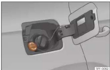
Fig. 204 AdBlue tank cap.
Operations prior to refilling
Park the vehicle on a flat surface and turn off the ignition. If the vehicle is on a slope or on a curb, the level indicator may not detect the refill properly.
If an AdBlue® warning message is shown on the instrument cluster display, fill with at least the minimum required amount (approx. 5 litres). Only after adding this amount will the system detect that AdBlue® has been added and you will be able to start the engine again. The maximum amount that can be refilled is 11 litres.
Fill with a refill bottle
Only use AdBlue® that complies with the ISO 22241-1 standard. Only use original containers.
》
Practical tips
- Open the tank cover>> Fig. 204.
- Unscrew the tank cap by turning it in an anti-clockwise direction.
- Please observe the manufacturer's instructions, indicated on the refill bottle.
- Check the expiry date.
- Remove the cap of the refill bottle.
- Insert the neck of the bottle in the tank filler neck vertically and screw the bottle on by hand, by turning it in a clockwise direction.
- Press the refill bottle in the direction of the filler neck and hold it in this position.
- Wait until the contents of the refill bottle have been poured into the AdBlue® tank. Do not compress or break the bottle!
- Turn the bottle in a counter-clockwise direction and gently pull it upwards >>> 0.
- The AdBlue tank is full when no more liquid comes out of the bottle.
- Screw on the tank cap in a clockwise direction until it is tightly closed.
- Close the fuel tank flap.
Operations before driving
• After refilling the tank, only switch on the ignition.
- Leave the ignition on for at least 30 seconds for the system to detect the fluid load.
• Make sure you wait for at least 30 seconds before starting the engine!
Refilling the dispenser with AdBlue
Valid for vehicles with selective catalytic reduction.
- Open the tank cap.
- Turn the SCR tank cap anti-clockwise
Fig. 204.
- Add AdBlue until the nozzle stops for the first time.
- Close the SCR tube by turning it clockwise until you hear a click.
WARNING
AdBlue® should only be stored in its original container, which should be tightly closed and kept in a safe place.
CAUTION
- When refilling, the nozzle grip should be aligned downward. Otherwise the nozzle will not connect automatically.
- Do not try to add any more additive after the nozzle has stopped for the first time. The AdBlue tank could overflow and AdBlue could spill out.
- Only use AdBlue® that complies with the ISO 22241-1 standard. Only use original containers.
-
Never mix AdBlue® with water, fuel or additives. Any type of damage caused by such a mixture will not be covered by the warranty.
-
Never pour AdBlue® into the fuel tank! This could result in engine damage.
- Do not carry the refill bottle inside the vehicle. If there is a leak (due to temperature changes or damage to the bottle), the AdBlue® may damage the vehicle's interior.
For the sake of the environment
Dispose of the refill bottle in an environ- ment-friendly manner.
Note
Suitable AdBlue® refill bottles can be purchased from SEAT dealerships.
Engine management and emissions control system
Introduction
WARNING
- Due to the high temperatures reached by the exhaust gas scrubbing system, you should not park your vehicle near a surface that can catch fire easily. Fire hazard!
- Do not apply wax underneath the vehicle around the area of the exhaust system: Fire hazard!
Checking and refilling levels
Control lamps

It lights up
Fault in the emission control system.
Reduce speed and drive carefully to the nearest specialised workshop to have the engine checked.

Flashes
Combustion failures that can damage the catalytic converter.
Reduce speed and drive carefully to the nearest specialised workshop to have the engine checked.

It lights up
Particulate filter blocked» page 321.

It lights up
Fault in the petrol engine management.
Have the engine checked as soon as possible by a specialised workshop.
When the ignition is switched on, the EPC (Electronic Power Control) lights up and should go off once the engine has started.

It lights up
Diesel engine preheating system.
The engine can be started straight away when the lamp switches off.

Flashes
Fault in the diesel engine management.
Have the engine checked as soon as possible by a specialised workshop.
Note
While the control lamps ☐, ☐, EPC or ☐ are on, there might be faults in the engine, fuel consumption may go up and the engine might lose power.
Catalytic converter
To maintain the useful life of the catalytic converter
- Only use unleaded petrol with petrol engines.
- Never run the fuel tank dry.
- When changing or adding engine oil, do not exceed the necessary amount »» page 328, Topping up the engine oil.
- Never tow the vehicle to start it, use jump leads if necessary»» page 52.
If you should notice misfiring, uneven running or loss of power when the car is moving, have the vehicle inspected by a specialised workshop. In general, the emissions warning lamp will light up when any of these symptoms occur. If this happens, any unburnt fuel can enter the exhaust system and escape into the atmosphere. The catalytic converter can also be damaged by overheating.

CAUTION
Never run the fuel tank completely dry because an irregular fuel supply can cause ignition faults. This allows unburnt fuel to enter the exhaust system, which could cause overheating and damage the catalytic converter.

For the sake of the environment
Even when the emission control system is working perfectly, there may be a smell of sulphur from the gases on occasions. This depends on the sulphur content of the fuel used. This can quite often be avoided by changing to another brand of fuel.
Particulate filter
√ Valid for: vehicles with petrol or diesel particulate filters
The particulate filter eliminates most of the soot from the exhaust gas system. Under normal driving conditions the filter cleans itself. If the filter does not clean itself (e.g. if short journeys are made continuously), it becomes blocked with soot and the following indication is displayed to the driver: Particulate filter: cleaned while the vehicle is moving. See Manual. The »
Practical tips
particulate filter needs cleaning (regeneration).
Regeneration of the particulate filter (only for 2.0l and 2.5l TSI engines)
Requirements for the regeneration journey: the engine is at operating temperature.
- Drive at a speed of at least 80 km/h >> △
- Completely remove your foot from the accelerator pedal for a few seconds to let the vehicle roll with the gear engaged.
- Consider the legal speed limits as well as the recommended gears.
- Repeat this procedure (accelerate and let roll) until the control lamp turns off.
This procedure involves an autonomous particulate filter cleaning process and may take some time.
If the warning lamp does not turn off, go immediately to a specialised workshop to repair the fault.
Regeneration of the petrol (except the 2.0l and 2.5l TSI engines) and diesel particulate filter
Requirements for the regeneration journey: the engine is at operating temperature.
- Drive at a speed of between 50-120 km/h (31-75 mph). This increases the temperature and burns the soot in the filter >> △.
- Consider the legal speed limits as well as the recommended gears.
• End the regeneration journey once the control warning lamp has gone out.
If the warning lamp stays on after 30 minutes of running in regeneration mode, have a specialised workshop repair the fault.
WARNING
Always adjust your speed to suit the weather conditions, roads, braking distance and traffic if the particulate filter is in its regeneration phase. Route recommendations should never make you disregard each country's specific traffic regulations.
CAUTION
- When the exhaust system detects that the particulate filter is close to saturation, the self-cleaning function of this system recommends optimal driving for this function.
- Due to the high temperatures caused by the regeneration of the particulate filter, it is possible that the radiator fan will activate after stopping the engine, even it its operating temperature has not been reached.
- Noise, smells and high idle speeds can occur during regeneration.
• Always use the correct engine oil and the correct fuel to make sure the useful life of
the particulate filter is not affected. Also avoid making short trips all the time.
Engine compartment
Working in the engine compartment
Always be aware of the danger of injury and scalding as well as the risk of accident or fire when working in the engine compartment (e.g. when checking and refilling fluids).
Always observe the warnings listed below and follow all general safety precautions.
The vehicle's engine compartment is a potentially hazardous area»» △
WARNING
When work is done in the engine compartment, injuries, burns, accidents and even fires can occur.
- Turn off the engine, disconnect the ignition and apply the electronic parking brake. If the vehicle has a manual gearbox, place the lever in neutral; if it has an automatic gearbox, activate the parking lock (button P). Wait for the engine to cool down.
- Never open the bonnet if you see steam or drips of coolant being released from the engine compartment. Wait until no steam
Checking and refilling levels
or coolant can be seen before opening the bonnet.
- Keep children away from the engine compartment.
- Never spill liquids used for vehicle operation on the engine compartment, as these may catch fire (e.g. the antifreeze in coolant).
- Avoid causing short-circuits in the electrical system, particularly at the points where the jump leads are attached » page 52. The battery could explode.
- If working inside the engine compartment, remember that, even when the ignition is switched off, the radiator fan may start up automatically, and therefore there is a risk of injury.
- Never cover the engine with additional insulating materials such as a blanket. Risk of fire!
- Do not unscrew the cap on the coolant expansion tank when the engine is hot. The cooling system is under pressure.
- Protect face, hands and arms by covering the cap with a large, thick rag to protect against escaping coolant and steam.
• Always make sure you have not left any objects, such as cleaning cloths or tools, in the engine compartment. - If you have to work underneath the vehicle, you must use suitable stands additionally to support the vehicle, there is a risk of accident!. A hydraulic jack is insufficient for
securing the vehicle and there is a risk of injury.
- If any work has to be performed when the engine is started or with the engine running, there is an additional, potentially fatal, safety risk from the rotating parts, such as the drive belts, alternator, radiator fan, etc., and from the high-voltage ignition system. You should also observe the following:
- Never touch the electrical wiring of the ignition system.
- Ensure that jewellery, loose clothing and long hair do not get trapped in rotating engine parts. Danger of death. Before starting any work remove jewellery, tie back and cover hair, and wear tight-fitting clothes.
- Never accelerate with a gear engaged without taking the necessary precautions. The vehicle could move, even if the handbrake is applied. Danger of death.
- Observe the following additional warnings if work on the fuel system or the electrical system is necessary:
- Always disconnect the battery from the on-board network.
- Do not smoke.
- Never work near naked flames.
- Always keep an approved fire extinguisher immediately available.
For the sake of the environment
- Inspect the ground underneath your vehicle regularly so that any leaks are detected at an early stage. If you find spots of oil or other fluids in the area where it was parked, have your vehicle inspected at the workshop.
- Service fluids leaks are harmful to the environment. For this reason you should make regular checks on the ground underneath your vehicle. If you find spots of oil or other fluids, have your vehicle inspected in a specialised workshop.
Note
In right-hand drive vehicles some brake fluid reservoirs are on the other side of the engine compartment>> Fig. 207.
Practical tips
Opening and closing the bonnet
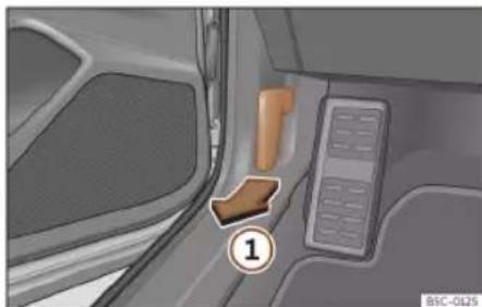
Fig. 205 Release lever in the driver's foot-well area.

Fig. 206 Lever under the bonnet.
Opening the bonnet
The bonnet is released from inside the vehicle.
Before opening the bonnet, make sure that the windscreen wiper arms are in place against the windscreen.
- Open the door and pull the lever under the dashboard»» Fig. 205 ①.
• To lift the bonnet, press towards the left on the lever located under the bonnet, in the centre>>Fig. 206 ② The arrester hooks are released. - The bonnet can be opened. Release the bonnet stay and secure it in the fixture designed for this in the bonnet.
Closing the bonnet
- Slightly lift the bonnet.
- Release the bonnet stay and replace it in its support.
- At a height of approximately 20 cm let it fall so it locks.
If the bonnet does not close, do not press downwards. Open it again and let it fall as mentioned above.

WARNING
Make sure that the bonnet is properly closed. If it opens when driving, it can cause an accident.

CAUTION
To avoid damage to the bonnet and to the windscreen wiper arms, only open it when the windscreen wipers are in place against the windscreen.
Checking and refilling levels
Checking levels

Fig. 207 Diagram for the location of the various elements.
From time to time, the levels of the different fluids in the vehicle must be checked. Never fill with incorrect fluids, otherwise serious damage to the engine may be caused.
① Coolant expansion tank»» page 329
② Brake fluid reservoir»» page 331
③ Engine oil filler cap»» page 328
④ Engine oil level dipstick» page 327
⑤ Battery>> page 333
⑥ Windscreen washer reservoir >> page 332
Note
The layout of parts may vary depending on the engine.
Practical tips
Engine oil
General notes

Fig. 208 In the engine compartment: engine oil label
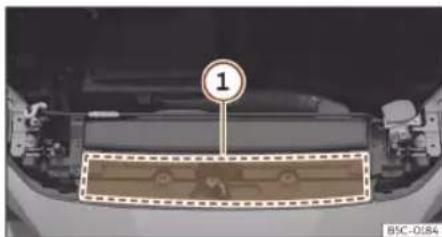
Fig. 209 In the engine compartment: area where the engine oil label is located
Key to the>>> Fig. 208 :
Ⓐ Information about the engine oil standard.
B Information about engine oil viscosity.
The engine comes with a special, multi-grade oil that can be used all year round.
Because the use of high-quality oil is essential for the correct operation of the engine and its long useful life, when topping up or changing oil, use only those oils that comply with VW standards.
For vehicles with an engine oil label
If the engine oil has to be topped up, use one of the oils shown on the label» Fig. 208. The label with the prescribed standard is located at the front of the engine compartment» Fig. 209 ①. If you use the recommended engine oil, you can top up the oil as often as necessary.
For vehicles without an engine oil label
Contact a specialised workshop or SEAT official service for information about the corresponding standard.
If the engine oil level is too low
If the recommended engine oil is not available, in the event of an emergency you can change the oil once with a maximum of 0.5 L of the next oil until the next oil change:
- Petrol engines: VW 504 00, ACEA C3 or API SN standard.
- Diesel engines: VW 507 00, ACEA C3 or API CJ-4, viscosity OW-30.
CUPRA recommends changing the oil at a specialised workshop. CUPRA recommends a specialised CUPRA Service or SEAT Official Service.
CUPRA recommends the use of engine oils approved according to the appropriate VW standard. Use of engine oils that do not meet these quality requirements can cause engine damage.
CUPRA recommends the use of Original SEAT Spare Part engine oils.
Engine oil additives
No type of additive should be mixed with the engine oil. The deterioration caused by these additives is not covered by the warranty.
CAUTION
Take the following into account if you have refilled with an engine oil different to those specified in the aforementioned standards, or by your SEAT technical service centre:
- There is no way of completely avoiding the danger of causing damage to the engine and particulate filter.
- You can continue driving with the vehicle if the refill was no more than 0.5 l of engine oil. Go to a specialised workshop as soon as possible and request an oil change. Otherwise, there is a danger of engine damage.
Checking and refilling levels
- If you have topped up more than 0.5 l of engine oil, drive with the engine at low load levels and within the medium RPM range as a maximum. Do not drive at more than 80 km/h and do not travel more than 300 km (approximately). Go to a specialised workshop as soon as possible and request an oil change. Otherwise, there is a danger of engine damage.
- You are responsible for the risk of possible damage to the vehicle (engine, exhaust system). If in doubt, do not start the engine and request assistance from the technical service centre.
- Do not start the engine if you have topped up with a fluid other than engine oil. Request assistance from the technical service centre. Danger of engine damage!
Note
Before a long trip, we recommend finding an engine oil that conforms to the corresponding VW specifications and recommend keeping it in the vehicle. This way, the correct engine oil will always be available for a top-up if needed.
Warning lamp
It lights up red
Do not carry on driving! Engine oil pressure too low. Switch off the engine. Check the engine oil level.
If this warning lamp 📋 starts to flash, and is accompanied by three audible warnings, switch off the engine and check the oil level. If necessary, add more oil >>page 328.
If the warning lamp flashes although the oil level is correct, stop driving. Do not even run the engine at idle speed! Obtain technical assistance.
It lights up yellow
Check the engine oil level as soon as possible. Replace oil as soon as you have the opportunity to do so >> page 328.
It flashes yellow
Fault in the oil level sensor. Have the check done by a specialised workshop. Until then it is advisable to check the oil level every time you refuel.
WARNING
Observe the safety warnings»» △ in Control and warning lamps on page 84.
Checking the engine oil level
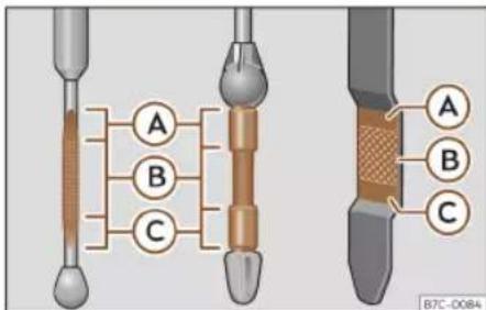
Fig. 210 Engine oil dipstick.
The engine oil dipstick indicates the level of the oil.
Checking oil level
– Park the vehicle in a horizontal position.
- Briefly run the engine at idle speed until the operating temperature is reached and then stop.
- Wait for about two minutes.
- Pull out the dipstick. Wipe the dipstick with a clean cloth and insert it again, pushing it in as far as it will go.
- Then pull it out once more and check the oil level>>> Fig. 210. Top up with engine oil if necessary.
The oil must leave a mark between zones A and C. It can never go above zone A.
Practical tips
- Zone A: do not add oil.
- Zone B: you can add oil but keep the level in that zone.
- Zone C: add oil until zone B.
Depending on how you drive and the conditions in which the vehicle is used, oil consumption can be up to 0.5 l/1000 km. Oil consumption is likely to be higher for the first 5,000 km. For this reason the engine oil level must be checked at regular intervals, preferably when filling the tank and before a journey.

WARNING
Any work carried out in the engine compartment or on the engine must be carried out cautiously.
- When working in the engine compartment, always observe the safety warnings >> page 322.

CAUTION
If the oil level is above area A, do not start the engine. This could result in damage to the engine and catalytic converter. Contact a Technical Service.
Topping up the engine oil
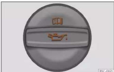
Fig. 211 In the engine compartment: Engine oil filler cap.
Before opening the bonnet, read and observe the warnings»» △ in Working in the engine compartment on page 322.
Topping up engine oil
- Unscrew cap from engine oil filler opening >> Fig. 211.
- Carefully add oil in small quantities (no more than 0.5 l).
• To avoid adding too much oil, whenever you add a certain amount, wait about 2 minutes and recheck the oil level» page 327.
• If necessary, add some more oil. - When the oil level reaches at least zone >> Fig. 210 B, unscrew the engine oil filler cap carefully >> 0.
The position of the oil filler opening is shown in the corresponding engine compartment illustration»»page 325.
Engine oil specification»» page 326.

WARNING
Oil is highly inflammable! Ensure that no oil comes into contact with hot engine components when topping up.

CAUTION
If the oil level is above area>> Fig. 210 A, do not start the engine. This could result in damage to the engine and catalytic converter. Contact a specialised workshop.

For the sake of the environment
The oil level must never be above zone >> Fig. 210 A. Otherwise oil can be drawn in through the crankcase breather and leak into the atmosphere via the exhaust system.

Note
Before a long trip, we recommend finding an engine oil that conforms to the corresponding VW specifications and recommend keeping it in the vehicle. This way, the correct engine oil will always be available for a top-up if needed.
Checking and refilling levels
Engine oil change
We recommend that you have the engine oil changed by a Technical Service.

WARNING
Only change the engine oil yourself if you have the specialist knowledge required!
- Before opening the bonnet, read and observe the warnings» page 322.
- Wait for the engine to cool down. Hot oil may cause burn injuries.
- Wear eye protection to avoid injuries, such as acid burns, caused by splashes of oil.
- When removing the oil drain plug with your fingers, keep your arm horizontal to help prevent oil from running down your arm.
- Wash your skin thoroughly if it comes into contact with engine oil.
- Engine oil is poisonous! Used oil must be stored in a safe place out of the reach of children.

CAUTION
No additives should be used with engine oil. This could result in engine damage. Any damage caused by the use of such additives would not be covered by the factory warranty.

For the sake of the environment
• We recommend that you change the engine oil and the filter at a technical service centre.
- Never pour oil down drains or into the ground.
- Use a suitable container when draining the used oil. It must be large enough to hold all the engine oil.
Cooling system
Coolant specifications
The engine cooling system is supplied from the factory with a specially treated mixture of water and at least 40 % of the additive G12evo (TL-VW 774 J), purple. This mixture gives the necessary frost protection down to -25°C (-13°F) and protects the light alloy parts of the engine cooling system against corrosion. It also prevents scaling and considerably raises the boiling point of the coolant.
To protect the cooling system, the percentage of additive must always be at least 40 %, even in warm climates where anti-freeze protection is not required.
If for weather reasons further protection is necessary, the proportion of additive may be increased, but only up to 60 %; otherwise antifreeze protection will diminish and this will worsen cooling.
When the coolant is topped up, use a mixture of distilled water and at least 40 % of the additive G12evo for optimal protection against corrosion. Mixing G12evo with G13 (TL-VW 774 J), G12 plus-plus (TL-VW 774 G), G12 plus (TL-VW 774 F), G12 (red) or G11 (green blue) engine coolants decreases protection again corrosion and should be avoided.

WARNING
If there is not enough anti-freeze in the coolant system, the engine may fail leading to serious damage.
- Ensure that the percentage of additive is correct for the lowest expected ambient temperature in the zone in which the vehicle is to be used.
- When the outside temperature is very low, the coolant could freeze and the vehicle would be immobilised.

CAUTION
The original additives should never be mixed with coolants which are not approved by SEAT.
- If the fluid in the expansion tank is not purple but is, for example, brown, this indicates that the G12evo additive has been
Practical tips
mixed with an inadequate coolant. The coolant must be changed as soon as possible if this is the case!

For the sake of the environment
Coolants and additives can contaminate the environment. If any fluids are spilled, they should be collected and correctly disposed of, with respect to the environment.
Coolant tank
√ Valid for: hybrid vehicles.
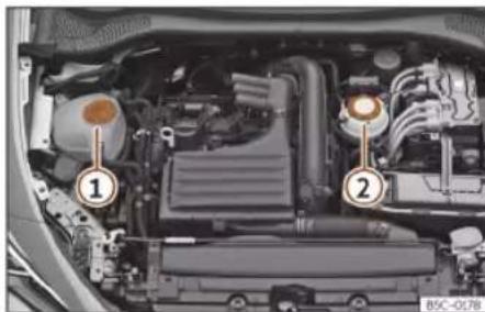
Fig. 212 Engine compartment: Coolant tanks
The vehicle has 2 independent coolant expansion tanks.
Fig. 212
① Coolant expansion tank for the combustion engine cooling circuit.
② Coolant expansion tank for the high-voltage cooling circuit. Do not continue driving if there is a lack of fluid in the expansion tank. Do not top up coolant. Go immediately to a specialised workshop.
Refilling coolant

Fig. 213 In the engine compartment: marking on coolant expansion tank.

Fig. 214 Engine compartment: coolant expansion tank cap.
The coolant tank is located in the engine compartment»» page 325.
Top up coolant when the level is below the MIN (minimum) mark.
Checking coolant level
- Park the vehicle in a horizontal position.
- Switch the ignition off.
- Read off the coolant level on coolant expansion tank. When the engine is cold, the coolant level should be between the marks >> Fig. 213. When the engine is hot, it may be slightly above the upper mark.
Topping up coolant
- Wait for the engine to cool down.
Checking and refilling levels
- Cover the coolant expansion tank cap with a cloth and carefully unscrew it to the left >> △
- Top up the coolant only if there is still coolant in the expansion tank, otherwise you could damage the engine. If there is no coolant in the expansion tank, do not continue driving. You should obtain professional assistance >>> 1.
- If there is still some coolant in the expansion tank, top up to the upper mark.
- Top up with coolant until the level becomes stable.
- Screw the cap back on correctly.
If there is a coolant leak, take the vehicle specialised workshop to have the cooling system examined.
WARNING
• The cooling system is under pressure. Do not unscrew the cap on the coolant expansion tank when the engine is hot: risk of burns!
- Store the antifreeze in its original container and keep it out of reach of children.
- If working inside the engine compartment, remember that, even when the ignition is switched off, the radiator fan may start up automatically, and therefore there is a risk of injury.
CAUTION
If you run out of coolant in the expansion tank, park the car in a safe place and do not continue driving. Obtain technical assistance.
Brake fluid
Check and refill the brake fluid
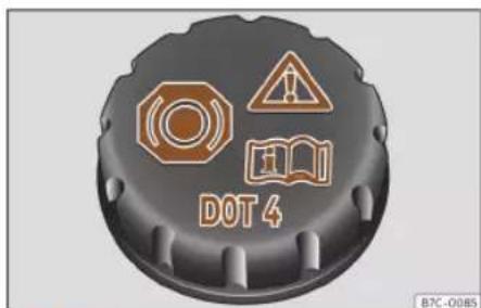
Fig. 215 Engine compartment: brake fluid reservoir cap.
The brake fluid reservoir is located in the engine compartment»» page 325.
Checking the brake fluid level
The brake fluid level must be between the MIN and MAX markings.
However, if the brake fluid level goes down noticeably in a short time, or drops below the MIN mark, there may be a leak in the brake system. Seek specialist assistance. A warning light on the instrument panel display monitors the brake fluid level» page 82.
In right-hand drive vehicles the brake fluid reservoir is on the other side of the engine compartment.
Changing brake fluid
We recommend that you have the brake fluid changed by a Technical Service.
WARNING
If the brake fluid level is low or unsuitable/old brake fluid is used, the brake system may fail or braking power may be reduced.
- Check the brake system and the brake fluid level regularly!
- When the brake fluid is used and brakes are subjected to extreme braking forces, bubbles of vapour form in the brake system. These bubbles can significantly reduce braking power, notably increasing braking distance, and could result in the total failure of the brake system.
- Be sure to always use the correct brake fluid. Only use brake fluid that expressly meets the VW 50114 standard.
Practical tips
- You can buy VW 50114 standard brake fluid at a specialised CUPRA service or at a SEAT Official Service. If none is available, use only high-quality brake fluid that meets DIN ISO 4925 CLASS 4 standards, or USA Standards FMVSS 116 DOT 4.
- The replacement brake fluid must be new.
- Brake fluid should be stored in the closed original container in a safe place out of reach of children. Risk of poisoning!

CAUTION
Brake fluid should not come into contact with the vehicle paintwork, as it is abrasive.

For the sake of the environment
Brake fluid is an environmental pollutant. Collect any spilt service fluids and allow a professional to dispose of them.
Windscreen washer reservoir
Checking the level of the window washer tank and refilling it
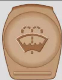
B7C-0103
Fig. 216 In the engine compartment: window washer tank cap.
The window washer tank is in the engine compartment»» page 325.
Check the water level in the windscreen washer reservoir regularly and top up as required.
The window washer tank contains liquid detergent for the windscreen and rear window.
- Open the bonnet ⚠️»» page 322.
- The window washer tank is marked with the 🔗 symbol on the cap.
- Check there is enough windscreen water in the reservoir.
Plain water is not enough to clean the wind-screen and headlights. We recommend that you always add a product to the windscreen washer fluid.
Recommended windscreen wipers
- For the hottest seasons we recommend summer G 052 184 A1 for clear glass. Proportions of the mixture in the washer fluid tank: 1:100 (1 part concentrate per 100 parts water).
- All year round, G 052 164 A2 for clear glass. Approximate proportion of the winter mixture, up to -18°C ( 0°F ): 1:2 (1 part concentrate per 2 parts water); otherwise, a 1:4 proportion of mixture in the washer fluid tank.
The capacity of the window washer tank can be found in»» page 367.

CAUTION
If the water from the windscreen washer does not contain enough anti-freeze, it may freeze on the windscreen and rear window, reducing forward and rear visibility.
- In winter, ensure the windscreen washer contains enough anti-freeze.
- In cold conditions, you should not use the windscreen wiper system unless you have
Checking and refilling levels
warmed the windscreen with the ventilation system. The antifreeze could freeze on the windscreen and reduce visibility.
CAUTION
Never mix an unsuitable antifreeze or other similar additives with the windscreen washer water. A greasy layer may be formed on the windscreen which will impair visibility.
- Use clean water with a window cleaner recommended by CUPRA.
- If necessary, add a suitable antifreeze to the water in the reservoir.
CAUTION
- Do not mix cleaning products recommended by CUPRA with other products. This could lead to flocculation and may block the windscreen washer jets.
- When topping up service fluids, make absolutely certain that you fill the fluids into the correct reservoirs. Using the wrong fluids could cause serious malfunctions and engine damage!
- Lack of window washer fluid causes the view through the windscreen to be obscured.
12-volt battery
General information
The battery is located in the engine compartment»» page 325 or luggage compartment (PHEV hybrid vehicles)»»page 335 and is practically maintenance free. It is checked as part of the Inspection Service. Nevertheless, check the terminals are clean and have the correct tightening torque, especially in summer and winter.
All work on batteries requires specialist knowledge. Please refer to a specialised CU-PRA Service, SEAT Official Service or a workshop specialising in batteries: risk of burns or exploding battery!
The battery must not be opened. Never try to change the fluid level of the battery. Otherwise explosive gas is released from the battery that could cause an explosion.
Battery warning indications
Wear eye protection.
Battery acid is extremely corrosive. Wear protective gloves and eye protection. Rinse any splashes of electrolyte with plenty of water.
Fires, sparks, open flames and smoking are prohibited.
The battery should only be charged in a well-ventilated zone. Risk of explosion!


Keep children away from acid and batteries!

Always follow the instruction manual.
Disconnecting the battery
The battery should only be disconnected in exceptional cases. When the battery is disconnected, some of the vehicle's functions are lost. These functions will require resetting after the battery is reconnected.
When disconnecting the battery from the vehicle on-board network, disconnect first the negative cable and then the positive cable.
Deactivate the anti-theft alarm before you disconnect the battery. Otherwise the alarm will be triggered.
If the vehicle is not used for long periods
The vehicle has a system for monitoring the current consumption when the engine is left unused for long periods of time»» page 337. Some functions, such as the interior lights, or the remote door opening, may be temporarily disabled to prevent the battery from running flat. These functions will come back on as soon as the ignition is switched on and the engine started.
》
Practical tips
Winter conditions
During the winter, the starting power may be reduced, and if necessary, the battery should be charged» page 336.

WARNING
Always be aware of the danger of injury and chemical burns as well as the risk of accident or fire when working on the battery and the electrical system:
- Wear eye protection. Protect your eyes, skin and clothing from acid and particles containing lead.
- Battery acid is extremely corrosive. Wear protective gloves and eye protection. Do not tilt the batteries. This could spill acid through the vents.
- Neutralise any electrolyte splashes on the skin, eyes or clothing with a soapy solution, and rinse off with plenty of water. If acid is swallowed by mistake, consult a doctor immediately.
- Fires, sparks, open flames and smoking are prohibited. When handling cables and electrical equipment, avoid causing sparks and electrostatic charge. Never short the battery terminals. High-energy sparks can cause injury.
-
A highly explosive mixture of gases is released when the battery is under charge. The batteries should be charged in a well-ventilated room only.
-
Keep children away from acid and batteries.
- Before working on the electrical system, you must switch off the engine, the ignition and all electrical devices. The negative cable on the battery must be disconnected. When a light bulb is changed, you need only switch off the light.
- Deactivate the anti-theft alarm by unlocking the vehicle before you disconnect the battery! The alarm will otherwise be triggered.
- When disconnecting the battery from the vehicle on-board network, disconnect first the negative cable and then the positive cable.
- Switch off all electrical devices before reconnecting the battery. Reconnect first the positive cable and then the negative cable. Never reverse the polarity of the connections. This could cause an electrical fire.
- Never charge a frozen battery, or one which has thawed. This could result in explosions and chemical burns. Always replace a battery which has frozen. A flat battery can also freeze at temperatures close to 0°C (+32°F) .
- Ensure that the vent hose is always connected to the battery.
- Never use a defective battery. This could cause an explosion. Replace a damaged battery immediately.

CAUTION
- Do not expose the battery to direct sunlight over a long period of time, as the intense ultraviolet radiation can damage the battery housing.
- If the vehicle is left standing in cold conditions for a long period, protect the battery from "freezing". If it freezes it will be damaged.
Control lamp
The control lamp lights up when the ignition is switched on. It should go out when the engine has started running.
Indicator lamps and driver messages on the instrument cluster display or infotainment system:

Defective alternator
√ Valid only for: conventional vehicles.
The control lamp lights up RED.
The vehicle battery stops charging from the alternator. You should immediately drive to the nearest specialised workshop.
You should avoid using electrical equipment that is not absolutely necessary because this will drain the battery.
Checking and refilling levels
Error: the 12 V vehicle battery is not charging. Park safely!
The control lamp lights up RED.
Stop driving! Stop the vehicle at the next opportunity and in a safe place.
The instrument cluster displays a message due to a DCDC failure (electrical, mechanical or energy balance).
- Switch the ignition off and seek professional assistance.
Error: 12V power supply. Park safely! Check the manual
The control lamp lights up RED.
Stop driving! Stop the vehicle at the next opportunity and in a safe place.
There is a serious fault in the 12V power supply.
- Go to a qualified establishment.
• Have the electrical system checked.
Error: 12 V vehicle battery. Engine cannot be started. Visit the workshop
The control lamp lights up YELLOW.
The connection between the on-board network and the 12-volt battery has been interrupted. If the drive system switches off in this situation, it should not be switched on again
and the vehicle should be jump started
page 52 or professional assistance should be sought.
- Go to a qualified establishment.
- Have the electrical system checked.
Low level of the 12 V vehicle battery. Charge while driving
The control lamp lights up YELLOW.
Starting capacity may be limited. If this driver message goes out after a certain amount of time, the vehicle's battery has recharged while driving and reached a sufficient level. If the driver message does not go out, take the vehicle to a specialized workshop.
Replace the 12V vehicle battery. Go to a workshop
The control lamp lights up YELLOW.
The 12 volt vehicle battery has almost reached the end of its useful life. Visit a professional and request an inspection and replacement, if necessary, of the 12-volt vehicle battery» page 336.
Error: The 12V power supply is currently limited. Drive with caution.
The control lamp lights up YELLOW.
The 12-volt power supply is limited, maybe because the 12 volt battery is discharged or not working at full performance. The 12-volt battery can be charged while driving. Until the warning disappears, you should drive with care.
Error: 12V power supply. Visit the workshop
There is a fault in the 12-volt power supply:
- Go to a qualified establishment.
• Have the electrical system checked.
Access to the 12 volt battery

Fig. 217 Hybrid vehicles (PHEV): location of the battery in the luggage compartment »
Practical tips
Valid for hybrid vehicles (PHEV)
The 12-volt vehicle battery is located under the luggage compartment floor.
- Open the luggage compartment.
- Raise the luggage compartment floor » page 137, to gain access to the 12-volt battery cover» Fig. 217.
- A suitable tool must be used to open and close the cover.
Valid for conventional vehicles
- Raise the bonnet >> △ in Working in the engine compartment on page 322.
- Lift the cover that protects the front of the battery» page 325,» Fig. 207.
Valid for VZ5 version: The 12-volt vehicle battery is located under the luggage compartment floor. To access it, lift up the luggage compartment floor» page 137.
Checking the battery electrolyte level
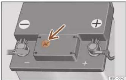
Fig. 218 Sight glass on the top of the 12 volt battery (schematic representation).
The electrolyte level should be checked regularly in high-mileage vehicles, in hot countries and in older batteries.
- Check the colour display in the "magic eye" on the top of the battery.
- If there are air bubbles in the window, tap the window gently until they disperse.
The "magic eye" indicator, located on the top of the battery changes colour, depending on the charge state and electrolyte level of the battery.
There are two different colours:
Yellow or colourless: The battery's electrolyte level is too low. Go to a specialised
workshop to have the battery checked and replaced if necessary.
Black: The battery's electrolyte level is correct.
Charging or changing the battery
If you often drive short distances or if the vehicle is not driven for long periods, the battery should be checked by a specialised workshop between the scheduled services. If the battery has discharged and you have problems starting the vehicle, the battery might be damaged. If this happens, we recommend you have the vehicle battery checked by a Technical Service where it will be re-charged or replaced.
Charging the battery
The vehicle battery should be charged by a specialised workshop only, as batteries using special technology have been installed and they must be charged in a controlled environment.
Replacing a vehicle battery
The 12-volt vehicle battery has been designed to suit its location and has specific safety features. If the battery needs to be replaced, it is recommended that it be installed by an official CUPRA qualified workshop.
Checking and refilling levels
These workshops have the technical documentation and equipment required to find out the size, technology, and maintenance and safety requirements of the new battery.
Always use maintenance-free batteries according to the TL82506 and VW75073 standards. These standards must be from October 2014 or later.
The degassing tube must always be connected to the hole on the negative pole side and the hole on the positive pole side must be sealed.
The vehicle's 12V battery must always be replaced by a qualified specialist company, as the vehicle's electronics must be adapted during replacement. In addition, the battery parameters for functional safety have been determined based on the original battery. Only a qualified specialist company has the right technology to fit the correct replacement battery.
The use of unsuitable batteries could invalidate the vehicle registration certificate.
Start-Stop systems (»» page 215) are equipped with a special battery. Therefore, it must only be replaced with a battery of the same specifications.
Your vehicle is equipped with an intelligent power management system to control the distribution of electrical energy» page 337. The power management function ensures
that the battery is charged much more efficiently than on vehicles without a power management system. To maintain this function after replacing the battery, we recommend that the replacement battery used is of the same make and type as the original fitted battery. To make proper use of the power management function after the battery has been changed, have the battery coded to the power management mode at a specialised workshop.
WARNING
• Always use only maintenance free batteries that do not run flat alone and whose properties, specifications and size correspond to the standard battery. The specifications are indicated on the battery case.
- Before starting any work on the batteries, you must read and observe the warnings
△ in General information on page 334.
For the sake of the environment
Batteries contain toxic substances such as sulphuric acid and lead. They must be disposed of appropriately and must not be disposed of with ordinary household waste.
Energy management
Optimisation of the starting capacity
The power management controls the distribution of electrical energy and thus helps to ensure that there is always enough power available to start the engine.
If a vehicle with a conventional electrical system is left parked for a long time, the battery will gradually lose its charge because certain electrical devices, such as the electronic gearbox lock continues to draw current even when the ignition is off. In some cases there may not be enough power available to start the engine.
Your vehicle is equipped with an intelligent power management system to control the distribution of electrical energy. This significantly improves reliability when starting the engine, and also prolongs the useful life of the battery.
The main functions incorporated in the power management system are battery diagnosis, residual current management and dynamic power management.
Battery diagnosis
The battery diagnosis function constantly registers the condition of the battery.
》
Practical tips
Sensors detect the battery voltage, battery current and battery temperature. This enables the system to calculate the current power level and charge condition of the battery.
Residual current management
The residual current management reduces power consumption while the vehicle is parked. It controls the supply of power to the various electrical devices while the ignition is switched off. The system takes the battery diagnosis data into consideration.
Depending on the power level of the battery, switch off the individual electrical devices one after the other to prevent the battery from losing too much charge and to ensure that the engine can be started reliably.
Dynamic power management
While the vehicle is moving, this function distributes the available power to the various electrical devices and systems according to their requirements. The power management ensures that on-board systems do not consume more electrical power than the alternator can supply, and thus maintains the maximum possible battery power level.
Note
- Neither is the power management system able to overcome the given physical limits.
Please remember that the power and useful life of the battery are limited.
- If there is a risk that the vehicle may not start, the alternator electrical failure or low battery charge level warning lamp will be shown >> page 334.
Flat battery
Starting ability has first priority.
Short trips, city traffic and low temperatures all place a heavy load on the battery. In these conditions a large amount of power is consumed, but only a small amount is supplied. The situation is also critical if electrical devices are in use when the engine is not running. In this case power is consumed when none is being generated.
In these situations you will be aware that the power management system is intervening to control the distribution of electrical power.
When the vehicle is parked for long periods
If you do not drive your vehicle for a period of several days or weeks, the power management will gradually shut off the electrical devices one by one or reduce the amount of current they are using. This limits the amount of power consumed and helps to ensure reliable starting even after a long pe-
riod. Some convenience functions, such as remote vehicle opening, may not be available under certain circumstances. These functions will be restored when you switch on the ignition and start the engine.
With the engine switched off
For example, if you listen to the sound system with the engine switched off the battery will run down.
If the energy consumption means there is a risk that the engine will not start, a text will be displayed in vehicles with a driver information system.
This driver indicator tells you that you must start the engine so that the battery can recharge.
When the engine is running
Although the alternator generates electrical power, the battery can still become discharged while the vehicle is being driven. This can occur when a lot of power is being consumed but only a small amount supplied, especially if the battery is not fully charged initially.
To restore the necessary energy balance, the system will then temporarily shut off the electrical devices that are using a lot of power, or reduce the current they are consuming. Heating systems in particular use a large amount of electrical power. If you notice, for
Wheels
instance, that the seat heating or the rear window heater is not working, they may have been temporarily switched off or regulated to a lower heat output. These systems will be available again as soon as sufficient electrical power is available.
You may also notice that the engine runs at a slightly faster idling speed when necessary. This is quite normal, and no cause for concern. The increased idling speed allows the alternator to meet the greater power requirement and charge the battery at the same time.
Wheels
Wheels and tyres
General notes
- When driving with new tyres, be especially careful during the first 500 km (300 miles).
- If you have to drive over a kerb or similar obstacle, drive very slowly and as near as possible at a right angle to the obstacle.
- Check from time to time if the tyres are damaged (punctures, cuts, cracks or dents). Remove any foreign objects embedded in the treads.
- Damaged wheels and tyres must be replaced immediately.
- Keep grease, oil and fuel off the tyres.
- Replace any missing valve caps as soon as possible.
- Mark the wheels before taking them off so that they rotate in the same direction when put back.
- When removed, the wheels or tyres should be stored in a cool, dry and preferably dark place.
Low profile tyres
Low profile tyres have a wider tread, a larger wheel diameter and a lower sidewall height. Therefore, its driving behaviour is more agile.
Low profile tyres may deteriorate more quickly than standard tyres, for instance due to strong knocks, potholes, manhole covers and kerbs. Correct tyre pressure is very important»» page 342.
To avoid damage to tyres and wheels, drive with special care when driving on roads in poor condition.
Visually check your wheels every 3000 km.
If the tyres or rims have received a heavy impact or have been damaged, have a specialised workshop check whether or not it is necessary to change the tyre.
Low profile tyres may deteriorate more quickly than standard tyres.
Concealed damage
Damage to tyres and rims is often not readily visible. If you notice unusual vibration or the car pulling to one side, this may indicate that one of the tyres is damaged. Reduce speed immediately if there is any reason to suspect that damage may have occurred. Inspect the tyres for damage. If no external damage is visible, drive slowly and carefully to the nearest specialised workshop and have the car inspected.
Practical tips
Foreign objects inserted in the tyre
- Do not remove foreign bodies if they have penetrated through the tyre wall!
- If the vehicle comes with a tyre mobility system, where necessary seal the damaged tyre as shown in section» page 44. Use a specialised workshop for repair or replacement. To do so, CUPRA recommends going to a specialised CUPRA dealer or any SEAT dealership.
The sealant at the lower part of the tyre tread wraps around the foreign body and provisionally seals the tyre.
Tyres with directional tread pattern
An arrow on the tyre sidewall indicates the direction of rotation on single drive tyres. Always note the direction of rotation indicated when mounting the wheel. This makes sure that optimal use is made of tyre properties in terms of aquaplaning, grip, excessive noise and wear.
Subsequent fitting of accessories
If you wish to change or fit wheels, rims or wheel trims, we recommend that you consult with a specialised CUPRA Service or SEAT Official Service centre for advice regarding current technical recommendations.
Speed symbols
The speed rating indicates the maximum speed permitted for the tyres.
P max. 150 km/h (93 mph)
Q max. 160 km/h (99 mph)
R max. 170 km/h (106 mph)
S max. 180 km/h (112 mph)
T max. 190 km/h (118 mph)
U max. 200 km/h (124 mph)
H max. 210 km/h (130 mph)
V max. 240 km/h (149 mph)
Z max. 240 km/h (149 mph)
W max. 270 km/h (168 mph)
Y max. 300 km/h (186 mph)
Some manufacturers use the letters "ZR" for tyres with a maximum authorised speed above 240 km/h (149 mph).
WARNING
- New tyres do not have maximum grip during the first 500 km. Drive particularly carefully to avoid possible accidents.
- Never drive with damaged tyres. This may cause an accident.
- If you notice unusual vibrations or if the vehicle pulls to one side when driving, stop
the vehicle immediately and check the tyres.
- Never use old tyres or those with an unknown history of use.
New wheels and tyres
It is best to have all wheels and tyres serviced by a specialised workshop. There they have the required knowledge, the special tools and the corresponding spare parts.
- Even winter tyres lose their grip on ice. If you have installed new tyres, drive the first 500 km carefully and at a moderate speed.
- All four wheels must be fitted with tyres of the same type, size (rolling circumference) and, if possible, tread pattern.
- When changing tyres, do not change just one; change at least two on the same axle.
- If you want to equip your vehicle with a combination tyres and rims that are different to those fitted in the factory, inform your specialised workshop before purchasing them >>
The sizes of the rims and tyres approved for your vehicle are listed in the vehicle documentation (e.g. EC Certificate of Conformity
Wheels
or COC document 1) . The vehicle documentation varies depending on the country of residence.
If the type of spare wheel is different form the normal wheels — e.g. in the case of winter tyres or particularly wide tyres — the spare wheel should only be used temporarily in the event of a puncture, and the vehicle should be driven with care. Refit the normal road wheel as soon as possible.
In vehicles with four-wheel drive, the 4 wheels must be fitted with tyres of the same brand, type and tread so that the traction system is not damaged by a difference in the number of turns of the wheels. Therefore, in the event of a puncture, only a spare wheel with the same perimeter as normal tyres should be used.
Manufacturing date
The manufacturing date is also indicated on the tyre sidewall (or on the inside face of the wheel):
DOT ... 2218 ...
it means, for example, that the tyre was manufactured in the 22nd week of 2018.
WARNING
- Use only combinations of tyres and rims, as well as suitable wheel nuts, approved by CUPRA. Otherwise the vehicle may be damaged, causing an accident.
- For technical reasons it is not possible to use wheels of other vehicles; in some cases not even wheels from the same vehicle model should be used.
• Always ensure that the tyres you have chosen have adequate clearance. When selecting replacement tyres, do not rely entirely on the nominal tyre size marked on the tyre, since the nominal tyre size can differ significantly depending on the manufacturer. Lack of clearance can damage the tyres or the vehicle and, as a result, endanger road safety. Risk of accident! - Only use tyres that are over 6 years old in an emergency, and drive with due care.
- The fitting of tyres with run-flat properties is not permitted on your vehicle! Prohibited use can cause accidents or can damage your vehicle.
• If decorative hubcaps are subsequently fitted, make sure that they allow enough air in to cool the braking system. Risk of accident! - Models with aerodynamic wheel rims and/or with bolt-on plastic elements (more
closed design) increase the likelihood of ice and snow accumulating on the inside. This should be taken into account, depending on the driving situations, as snow or ice accumulated in the wheels can cause vibration in the vehicle when it drives at over 40 km/h. It is advisable to remove ice and snow from the inside of the wheels using hot water.
- If you drive on dirt or gravel tracks, the likelihood of stones becoming trapped inside wheel rims with plastic elements increases when driving at high speed or in a sporty manner. If you see that there are stones trapped between the aluminium wheel rim and the insert, you can attempt to remove them using pressurised water.
For the sake of the environment
Old tyres must be disposed of according to the laws in the country concerned.
Note
- A CUPRA Service Centre should be consulted to find out whether wheels or tyres of different sizes to those originally fitted by CUPRA can be fitted, and to find out about the combinations allowed between the front axle (axle 1) and the rear axle (axle 2).
Practical tips
- Never mount used tyres if you are not sure of their "previous history".
Tyre life

Fig. 219 Location of the tyre pressure sticker.
Correct inflation pressures and sensible driving habits will increase the useful life of your tyres.
- Check tyre pressure at least once a month, and also prior to any long trip.
-
The tyre pressure should only be checked when the tyres are cold. Do not reduce the pressure of warm tyres.
-
Adjust tyre pressure to the load being carried by the vehicle»» Fig. 219.
- In vehicles with a tyre pressure indicator, save the modified tyre pressure»» page 346.
- Avoid fast cornering and hard acceleration.
- Inspect the tyres for irregular wear from time to time.
Tyre pressure
The tyre inflation pressures are listed on a sticker on the rear of the front left door frame»»Fig. 219.
Insufficient or excessive pressure greatly reduces the useful life of the tyres and adversely affects vehicle performance and ride. Correct inflation pressures are very important, especially at high speeds.
The tyre pressure must be adjusted according to the load the vehicle is carrying. If the vehicle is going to carry the maximum load, the tyre pressure should be increased to the maximum value indicated on the sticker >> Fig. 219.
Do not forget the spare wheel when checking the tyre pressures: Keep this spare wheel inflated to the highest pressure required for the road wheels.
In the case of a minimised temporary spare wheel (125/70 R18) inflate to a pressure of 4.2 bar as indicated on the tyre pressure label» Fig. 219.
Driving style
Fast cornering, heavy acceleration and hard braking (squealing tyres) all increase tyre wear.
Wheel balance
The wheels on new vehicles are balanced. However, certain circumstances may lead to imbalance (run-out), which is detected as vibrations in the steering wheel.
Unbalanced wheels should be rebalanced, as they otherwise cause excessive wear on steering, suspension and tyres. A wheel must also be rebalanced when a new tyre is fitted or if a tyre is repaired.
Incorrect wheel alignment
Incorrect running gear alignment causes excessive tyre wear, impairing the safety of the vehicle. If you notice excessive tyre wear, you should check wheel alignment at a specialised CUPRA Service or SEAT Official Service.

WARNING
Unsuitable handling of the wheels and tyres may lead to sudden tyre pressure losses, to tread separation or even to a blow-out.
• The driver is responsible for ensuring that all of the vehicle tyres are correctly inflated to the right pressure. The recommended
Wheels
tyre pressure is indicated on the label >> Fig. 219.
- Check tyre pressures regularly and ensure they are maintained at the pressures indicated. Tyre pressure that is too low could cause overheating, resulting in tread detachment or even burst tyres.
- When the tyres are cold, tyre pressure should be that indicated on the label >> Fig. 219.
- Regularly check the cold inflation pressure of the tyres. If necessary, change the tyre pressure of the vehicle tyres while they are cold.
- Regularly check your tyres for damage and wear.
- Never exceed the maximum permitted speed or loads specified for the type of tyre fitted on your vehicle.

For the sake of the environment
Under-inflated tyres will increase fuel consumption.
Tread wear indicators

Fig. 220 Tyre profile: tread wear indicators.

Fig. 221 Interchanging tyres.
Wear indicators around 1.6 mm high can be found on the base of the original tyre treads, ordered at regular intervals and running across the tread>> Fig. 220. The letters
"TWI" or triangles on the sidewall of the tyre mark the position of the wear indicators.
The minimum permitted profile depth 1 have been reached when the tyres have worn down to the wear indicators. Replace the tyres with new ones >> △.
Changing wheels around
To ensure that the wear is equal on all tyres the wheels should be changed round from time to time according to the system >> Fig. 221. The useful life of all the tyres will then be about the same time.
WARNING
The tyres must be replaced at the latest when the tread is worn down to the tread wear indicators. Failure to follow this instruction could result in an accident.
• Particularly in difficult driving conditions such as wet or icy roads. It is important that the tyre tread be as deep as possible and be approximately the same on the tyres of both the front and the rear axles.
- The scant driving safety due to insufficient tread depth is particularly evident in vehicle handling, when there is a risk of "aquaplaning" in deep puddles of water
Practical tips
and when driving through corners, and braking is also adversely affected.
- The speed has to be adapted accordingly, otherwise there is a risk of losing control over the vehicle.
Wheel nuts
The wheel nuts are matched to the rims. When installing different wheels (for instance alloy wheels or wheels with winter tyres) it is important to use the correct wheel nuts with the right length and correctly shaped bolt heads. This ensures that wheels are fitted securely and that the brake system functions correctly.
The wheel nuts must be clean and turn easily.
A special adapter is required to remove the anti-theft wheel bolts» page 47.
WARNING
Wheel nuts should never be greased or oiled.
- Use only wheel nuts which belong to the wheel.
- If the prescribed torque of the wheel nuts is too low, they could loosen whilst the ve-
hicle is in motion. Risk of accident! If the tightening torque is too high, the wheel nuts and threads can be damaged.
CAUTION
See»» page 49 to find out the recommended tightening torque for wheel nuts for steel and alloy rims.
Winter tyres
- Winter tyres must be fitted on all four wheels.
- Only use winter tyres that are approved for your vehicle.
- Please note that the maximum permissible speed for winter tyres may be lower than for summer tyres.
- Also note that winter tyres are no longer effective when the tread is worn down.
- After fitting the wheels you must always check the tyre pressures. When doing so, take into account the correct tyre pressures listed on the rear of the front left door frame»» page 342.
In winter road conditions winter tyres will considerably improve vehicle handling. The
design of summer tyres (width, rubber compound, tread pattern) gives less grip on ice and snow. This applies particularly to vehicles equipped with wide section tyres or with high speed tyres (code letters H, V or Y on the sidewall).
Only use winter tyres of the correct type approved for your vehicle. The sizes of these tyres are specified in the vehicle's documents (e.g. EC Certificate of Conformity or COC 1) ). The vehicle documentation varies depending on the country of residence.
Winter tyres lose a great deal of their properties when the tread is worn down to a depth of 4 mm.
The performance of winter tyres is also severely impaired by ageing, even if the tread is still much deeper than 4 mm.
A code letter indicating the speed limit is stamped on all winter tyres»» page 340.
Vehicles capable of exceeding these speeds must have an appropriate sticker attached so that it is visible to the driver. Suitable stickers are available at specialised CUPRA Services, SEAT Official Service centres and specialised workshops. Please note the regulations to this effect in your country.
"All-weather" tyres can also be used instead of winter tyres.
Wheels
Using winter tyres with V-rating
Please note that the generally applicable 240 km/h (149 mph) speed for winter tyres with the letter V is subject to technical restrictions; the maximum permissible speed for your vehicle may be significantly lower. The maximum speed limit for these tyres depends directly on the maximum axle weights for your car and on the listed weight rating of the tyres being used.
It is best to contact a specialised CUPRA Service or SEAT Official Service to check the maximum speed which is permissible for the V-rated tyres fitted on your car on the basis of this information.

WARNING
Exceeding the maximum speed permitted for the winter tyres fitted on your car can cause tyre failure, resulting in a loss of control of the vehicle – risk of accident.

For the sake of the environment
When winter is over, change back to summer tyres at an appropriate moment. In temperatures above +7°C (+45°F), performance will be improved if summer tyres are used. Fuel consumption, wear and noises while driving will all be reduced.
Snow chains
Snow chains must only be fitted to the front wheels, even on vehicles with four-wheel drive.
- Check that they are correctly seated after driving for a few yards; correct the position if necessary, in accordance with the manufacturer's fitting instructions.
- Keep your speed below 50 km/h (30 mph).
- If there is a danger of being trapped despite having fitted the chains, it is best to disable the traction control (TCS) in the ESC >> page 272, Connecting and disconnecting the ESC and TCS.
Snow chains will improve braking ability as well as traction in winter conditions.
For technical reasons snow chains may only be used with the following wheel rim/tyre combination.
Tyres Wheel rim Chains
| 215/55 R17 7.5Jx17ET40 Max. link 15 mm | |
| 225/55 R17 7.5Jx17ET40 | Max. link 9 mm |
| 225/50 R18 8x18 ET40 | |
| 245/45 R18 8x18 ET40 | |
| 245/40 R19 8x19 ET40 | |
Other dimensions do not allow chains
Remove any central wheel trims before fitting snow chains.

WARNING
The use of unsuitable or incorrectly fitted chains could lead to serious accidents and damage.
• Always the appropriate snow chains.
- Observe the fitting instructions provided by the snow chain manufacturer.
- Never exceed the maximum permitted speeds when driving with snow chains.

CAUTION
- Remove the snow chains to drive on roads without snow. Otherwise they will impair vehicle handling, damage the tyres and wear out very quickly.
- Wheel rims may be damaged or scratched if the chains come into direct contact with them. CUPRA recommends the use of coated snow chains.
Practical tips
Tyre pressure monitor sys- tem
Control lamp

It lights up
The inflation pressure of one or more wheels is much lower than the value set by the driver, or the tyre has structural damage.
In addition, a audible warning sounds and a text message is displayed on the instrument panel screen.
Stop the vehicle! Stop the vehicle safely as soon as possible. Check all tyres and pressures. Replace any damaged tyres.

Flashes
System fault
The control lamp flashes for approximately 1 minute and then lights up permanently.
If the tyre is inflated correctly, switch the ignition off and on again. Re-calibrate the tyre pressure monitor indicator»» page 346. If the fault continues, go to a specialised workshop.
Several control and warning lamps light up for a few seconds when the ignition is switched on while the function is verified. They will switch off after a few seconds.

WARNING
Observe the safety warnings>>> in Control and warning lamps on page 84.
Tyre pressure monitor indicator

Fig. 222 Instrument panel: warning of loss of tyre pressure.
The tyre pressure monitoring system compares the individual speeds of each wheel and thus the dynamic radius with the help of the ABS sensors.
If the rolling circumference of one or more wheels has changed, the tyre pressure monitoring indicator will indicate this on the instrument panel through a warning lamp and a warning to the drive» Fig. 222. When only one specific tyre is affected, its position within the vehicle will be indicated.
(1) Loss of pressure: Check left tyre pressure!
Wheel tread change
The wheel diameter changes when:
- Tyre pressure is changed manually.
- Tyre pressure is insufficient.
• The tyre structure is damaged. - The vehicle is unbalanced because of a load.
- The wheels on an axle are subject to a heavier load (e.g. with a heavy load).
- The vehicle is fitted with snow chains.
• The temporary spare wheel is fitted. - The wheel on one axle is changed.
There may be a delay in the reaction of the tyre pressure monitoring indicator(1) or it may not indicate anything under certain circumstances (e.g. sporty driving, snow-covered or unpaved roads, or when driving with snow chains).
Calibrate the tyre pressure monitoring indicator
After changing the tyre pressure or replacing one or more wheels, the tyre pressure monitoring indicator must be recalibrated. Do the same, for example, when the front and rear wheels are swapped.
- Switch the ignition on.
- Memorise the new inflation pressure in the Infotainment system: function button ➕ ➕ Driving data > Vehicle status» page 88.
- OR: from the instrument cluster's Service menu»» page 69.
Wheels
When driving, the system self-calibrates the tyre pressure provided by the driver and the wheels fitted. After a long journey with varied speeds the programmed values are collected and monitored.
With the wheels under very heavy loads, the tyre pressure must be increased to the total recommended tyre pressure before calibration>> Fig. 219.
WARNING
When the tyres are inflated at different pressures or at a pressure that is too low then a tyre may be damaged resulting in a loss of control of the vehicle and a serious or fatal accident.
- If the lamp (L) lights up, reduce speed immediately and avoid any sudden turning or braking manoeuvre. Stop when possible, and check the tyre pressure and status.
• The tyre pressure monitoring system can only operate correctly if all of the tyres are inflated to the correct pressure when cold. - If a tyre has not been punctured and it does not have to be changed immediately, drive to the nearest specialised workshop at a moderate speed and have the tyre checked and inflated to the correct pressure.
Note
- Driving for the first time with new tyres at a high speed can cause them to slightly expand, which could then produce an air pressure warning.
- If excessively low tyre pressure is detected with the ignition on, an audible warning will sound. In the event that there is a fault in the system, an audible warning will sound.
- Driving on dirt tracks for a long period of time or driving in a sporty style can temporarily deactivate the TPMS. The control lamp shows a fault, but disappears when road conditions or the driving style change.
- Do not only rely on the tyre pressure monitoring system. Regularly check your tyres to ensure that the tyre pressure is correct and that the tyres are not damaged due to puncture, cuts, tears and impacts/dents. Remove objects from the tyres only when they have not pierced the tyres.
- The tyre pressure monitoring indicator does not function when there is a fault in the ESC or ABS» page 269.
Spare wheel
Location and use of the temporary spare wheel
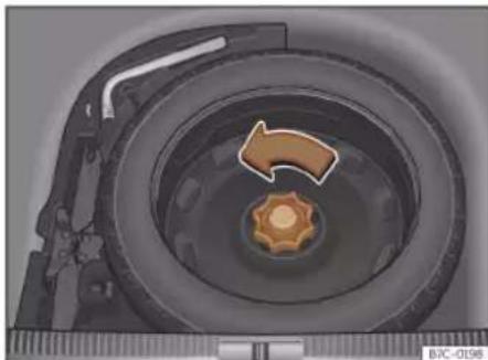
Fig. 223 In the luggage compartment: load floor raised.
»
Practical tips

Fig. 224 In the luggage compartment: remove the subwoofer.
The temporary spare wheel is stored under the floor panel in the luggage compartment and is attached by a thumbnut.
The temporary spare wheel has been designed to be used for short periods of time. Have the tyre checked and replaced as soon as possible at a specialised CUPRA Service, SEAT Official Service or at a specialised workshop.
The spare wheel must not be switched for a spare wheel from another vehicle.
Removing the temporary spare wheel
- Lift and hold up the floor panel to remove the temporary spare wheel»» page 137.
- Turn the thumb wheel anti-clockwise >> Fig. 223.
• Take out the temporary spare wheel.
Getting the spare wheel out of vehicles with BEATS Audio 10 speakers (with subwoofer)
To remove the spare wheel, you must first remove the subwoofer.
- Vehicles without a variable floor in the luggage compartment: pull the floor of the luggage compartment (carpet) upwards to get it out.
- Vehicles with a variable luggage compartment floor: lift and secure the floor luggage compartment as explained in» page 137.
- Disconnect the subwoofer>>> Fig. 224 ① speaker cable.
- Turn the securing wheel in an anti-clockwise direction» Fig. 224 ②.
- Remove the subwoofer speaker and the spare wheel.
- When re-mounting the spare tyre, place the subwoofer on the base of the wheel rim with care. When doing so, the tip of the "FRONT" arrow on the subwoofer should point forward.
- Reconnect the speaker cable and firmly rotate the securing wheel clockwise so that the subwoofer system and wheel are firmly in place.
Chains
For technical reasons, snow chains must not be used on the temporary spare wheel.
If you have a puncture on one of the front wheels when using snow chains, fit the temporary spare wheel in place of one of the rear wheels. Fit the snow chains on the rear wheel that you have removed and replace the punctured front wheel with this wheel.
WARNING
- After fitting the temporary spare wheel, check the tyre pressures as soon as possible. Failure to do so may cause an accident. The tyre pressure is listed on the back of the left front door frame» Fig. 219.
- Do not drive at over 80 km/h (50 mph) when the temporary spare wheel is fitted on the vehicle: risk of accident!
- Never travel more than 200 km using a temporary spare wheel.
- Avoid heavy acceleration, hard braking and fast cornering: risk of accident!
- Never use more than one temporary spare wheel at the same time, risk of accident.
- No other type of tyre (normal summer or winter tyre) may be fitted on the compact temporary spare wheel rim.
- If you are driving using the spare wheel, the ACC system could automatically switch
Wheels
off during the journey. Switch off the system when starting off.
Maintenance
Maintenance
Service
Service intervals
Service work and the Digital Maintenance Plan
Log of services performed ("Digital Maintenance Plan")
Specialised CUPRA dealers, SEAT dealerships or a specialised workshop records Service receipts in a central system. Thanks to this comprehensive documentation of the service history, it is possible to reproduce the services performed any time. CUPRA recommends requesting a Service receipt after every service carried out containing all the services carried out on the system.
Whenever there is a new service the receipt is replaced with a current one.
The Digital Maintenance Plan is not available in some markets. In this case, your specialised CUPRA dealer or a SEAT dealership will inform you about the current documentation of the work.
Service works
In the Digital Maintenance Plan, your specialised CUPRA dealer, SEAT dealership or a specialised workshop will document the following information:
- When each one of the services was carried out.
- Whether a specific repair has been suggested, e.g. changing the brake pads in the near future.
- If you have expressed a special request for the maintenance. Your Service Advisor will write the work order.
- The components or fluids that were changed.
• The date of the next service.
The Long Life Mobility Warranty is valid until the next inspection. This information is documented in all checks performed.
The type and the volume of the service may vary from one vehicle to another. A specialised workshop will be able to provide specific information on the jobs for your vehicle.
WARNING
If the services are insufficient or not performed and if the service intervals are not observed, the vehicle may be immobilised in traffic cause an accident and severe injuries.
• Make sure that any repairs are carried out by a specialised CUPRA dealer, a SEAT dealership or a specialised workshop.
CAUTION
CUPRA cannot be held liable for any damage to the vehicle due to insufficient work or of lack of availability of spare parts.
Note
Regular services on the vehicle not only maintain its value, but also its correct operation and road safety. For this reason, conduct the services in accordance with CU-PRA guidelines.
Set Service or Flexible Service Intervals
Services are classified as oil change service and inspection. The service interval display on the instrument panel display serves as a reminder of the next service.
Depending on the features, the engine and the conditions of use of the car, either the Fixed service or the Flexible service will be applied for an oil change service..
Service
How to know which type of service needs to his vehicle
- Check the tables below:
Oil change service a)
| PR No. | Type of service | Service interval |
| Q11 | Fixed | Every 5000 km or after 1 yearb) |
| Q12 | Every 7500 km or after 1 yearb) | |
| Q13 | Every 10000 km or after 1 yearb) | |
| Q14 | Every 15000 km or after 1 yearb) | |
| Q16 Flexible | According to the service interval display |
a) The data are based on normal conditions of use.
b) Whatever happens first.
Inspection Service a)
According to the service interval display
a) The data are based on normal conditions of use.
Particular characteristics of the Flexible Service
Regarding the Flexible Service, the oil change service only has to be performed when the vehicle needs it. To calculate when
you have to carry out this service, take into account the individual conditions of use and personal driving style. A major component of the flexible service the use of LongLife oil instead of conventional engine oil.
Bear in mind the information about the specifications of the engine oil according to the VW standard»» page 326.
If you do not want to the flexible service you can select the fixed service However, a fixed service may affect service costs The Service Advisor will gladly advise you.
Service interval display
At CUPRA, the dates of the services are indicated by the service interval display on the instrument panel» page 79 or in the Vehicle settings menu of the infotainment system» page 85.
The service interval display gives information for service dates that involve an engine oil change or an inspection. When the time for the corresponding service comes, additional work required, such as the change of brake fluid and the spark plugs, can be carried out.
Information about the terms of use
The service intervals and groups are usually based on normal conditions of use.
If, on the other hand, the vehicle is under adverse conditions of use, some of the work must be carried out before the next service period or even between service intervals.
Conditions of use adverse include:
- The use of fuel with a high sulphur content.
- Frequent short trips.
- Letting the engine idle for a long period of time, as in the case of taxis.
• Using the vehicle in areas with thick dust. - Frequent driving with a trailer (depending on equipment).
• Using the vehicle mostly in situations with a lot of traffic and stops (e.g. in a city).
• Using the vehicle mostly in winter.
This applies especially for the following parts (depending on equipment):
- Dust and pollen filter
• Air Care allergen filter - Air filter
- Toothed chain
- Particulate filter
- Engine oil
The Service Advisor of your specialised workshop will gladly inform you about the »
Maintenance
need of performing service work between normal service intervals, always considering the conditions of use of your vehicle.

WARNING
If the services are insufficient or not performed and if the service intervals are not observed, the vehicle may be immobilised in traffic and cause accidents and severe injuries.
• Make sure that any repairs are carried out by a specialised CUPRA dealer, a SEAT dealership or a specialised workshop.

CAUTION
CUPRA cannot be held liable for any damage to the vehicle due to insufficient work or of lack of availability of spare parts.
Service sets
Sets of services include all the maintenance works needed to ensure the safety and the smooth running of the vehicle (depending on the conditions of use and the features of the vehicle, such as the engine, gearbox, or operating fluids). Maintenance services are divided into inspection and review services. Consult the details of the jobs required for your vehicle at:
- Your CUPRA dealer
- Your SEAT dealership
- Your specialised workshop
Due to technical reasons (continuous development of components) the sets of services may vary. Your specialised CUPRA dealer, any SEAT dealership or a specialised workshop always receives updated information about any modifications that are made.
Additional service offers
Approved spare parts
Original SEAT Spare Parts have been conceived for their vehicles and approved by SEAT, with a special emphasis on safety. These parts correspond exactly to the manufacturer's requirements in terms of design, accuracy of the measurements and materials. The original SEAT Spare Parts have been conceived exclusively for your vehicle. For this reason, we always recommend the use of Original SEAT Spare Parts. SEAT cannot be held liable for the safety and suitability of parts from other manufacturers.
Approved spare parts
Approved spare parts, following the manufacturer's requirements, are an additional
service to you, offering the possibility of replacing complete sets, such as: light engine, gearboxes, heads, control units, electrical components, etc.
These parts are, approved parts, and are the same as the factory parts, which are also approved spare parts.
Original accessories
We recommend you only use CUPRA Original Accessories and CUPRA approved accessories for your vehicle. The reliability, safety and suitability of these accessories have been inspected specifically for this type of vehicle. CUPRA cannot be held liable for the safety and suitability of parts from other manufacturers.
Mobility Service (Service Mobility)
Since the moment you purchase your CU-PRA vehicle you will be able to enjoy the benefits and coverage of the CUPRA Mobility Service.
For the first two years after the purchase, your new CUPRA vehicle is automatically covered by the CUPRA Mobility Service without additional costs.
Vehicle maintenance
If you wish to enjoy this service after this period, you can extend the Mobility Service as long as you carry out the recommended Inspection and Maintenance Services at a specialised CUPRA Service or SEAT Official Service.
If your CUPRA vehicle is immobilised due to a fault or an accident, our assistance services will help you keep moving.
Take into account that the Mobility Service differs depending on the country where the vehicle was purchased. For further information, ask your specialised CUPRA dealer, any SEAT dealership or visit the CUPRA website in your country.
Warranty
Fault-free operation warranty
Specialised CUPRA Services or SEAT Official Services ensure the perfect condition of new vehicles. Check the purchase agreement or complementary additional documentation provided by your Technical Service to see the conditions and the terms of the warranty. Consult further information in this regard in your specialised CUPRA Service or SEAT Official Service.
Commercial warranty for high voltage batteries for electric and hybrid vehicles
To supplement the aforementioned warranties and guarantees, SEAT Official Services also grant a guarantee for high voltage batteries existing in many countries.
Consult the details of this guarantee in the sales contract or contact a SEAT Official Service.
Vehicle maintenance
Maintenance and cleaning
Basic observations
Regular and careful care helps to maintain the value of your vehicle. In addition, it may become a prerequisite to demand the warranty in the event of corrosion damage and deficiencies in the paint coat of the bodywork.
Specialised workshops have the necessary care products. Please follow the instructions for application on the packaging.

WARNING
- Cleaning products and other materials used for car care can be damaging to your health if misused.
• Always keep care products in a safe place, out of the reach of children. Danger of poisoning!

For the sake of the environment
- When purchasing car care products, chose products that are compatible with the environment.
- The waste from car-care products should not be disposed of with ordinary household waste.
Maintenance
Washing the vehicle
The longer you take to clean the tanks, e.g. remains of insects, bird excrements, tree resin or anti frost salt adhered to your vehicle, the more damage it can cause to the surface. High temperatures, for instance strong sunlight, further intensify the damage.
Before washing the car, soften the dirt using plenty of water.
To remove encrusted dirt such as insects, bird droppings or tree resin, use a lot of water and a microfibre cloth.
Have the underside of the vehicle washed after the end of the anti frost salts in winter.
High pressure cleaning equipment
When washing the vehicle with a high-pressure cleaner, always follow the operating instructions for the equipment. This applies particularly to the operating pressure and the distance between the spraying water. Do not aim the jet directly to the side window gaskets, doors, covers or the panoramic sun-roof; the same applies to tyres, rubber hoses, soundproofing material, sensors or camera lenses. Keep a distance of at least 40 cm.
Do not remove snow and ice with a high-pressure cleaner.
Do not use a nozzle that sprays the water out in a direct stream or one that has a rotating jet for forcing off dirt.
The water temperature must not exceed 60° C.
Automatic car washes
Spray the vehicle before starting the car wash.
Make sure that the windows and the panoramic sunroof are closed and the windscreen wipers are deactivated. Bear in mind the instructions of the car wash tunnel operator, especially if your vehicle has detachable parts.
Use of car washes without brushes if possible.
Washing by hand
Clean your vehicle from top to bottom with a soft sponge or with a brush. Only use cleaning products that do not contain solvents.
Washing vehicles with a matte paint by hand
To prevent damage to the vehicle when washing it, first remove the thicker dust and dirt. To remove traces of insects, grease and fingerprints, it is best to use a special cleaner for matte paint.
Apply the product with a microfibre cloth. To avoid damaging the surface of the paint, do not apply too much pressure.
Rinse with plenty of water. Then clean it with a neutral cleaning product and a soft micro-fibre cloth.
Rinse the vehicle again with plenty of water and then leave it to dry. Remove traces of water with a leather cloth.

WARNING
- Only wash the vehicle with the ignition switched off or according to the specifications of the car wash tunnel operator. Risk of accident!
- When cleaning the underbody or the inside of the wheel arches, protect yourself from sharp or pointy metal parts. Risk of cut!
- After cleaning the brakes could act more slowly due to moisture or, in winter, the ice on the brake discs and pads. Risk of accident! In this case the brakes should be dried by pressing the brake pedal several times.

CAUTION
- Before washing the vehicle in an automatic car wash, please make sure to retract the exterior mirrors to prevent them from being damaged. Electric exterior rearview
Vehicle maintenance
mirrors must always be folded/deployed electrically!
- Do not wash the vehicle in direct sunlight. Risk of damaging the paint job!
-
Do not use sponges, abrasive household sponges or similar to clean insect remains. Risk of damaging the surface!
• Vehicle parts with matte paint: -
Do not use polish or hard wax. Risk of damaging the surface!
- Never select washing programs that include the use of wax. This could damage the appearance of matte paint.
- Do not put stickers or magnets on parts with matte paint, as removing them may damage the paint.

For the sake of the environment
The car should only be washed in special wash bays. These places are prepared to prevent oily water from getting into the public drains.
Cleaning and maintenance instructions
The cleaning and maintenance of individual components of the vehicle can be checked in the following tables. The contents should be understood merely as a recommendation. Go to your specialised workshop if you
have special questions or parts that are not listed. Take he general considerations into account >> △ in Take special care with... on page 358.
Cleaning the exterior
Windscreen wipers
Problem Solution
Dirt Soft cloth with wipers
Headlights / Tail lights
Problem Solution
Dirt Soft sponge with neutral soap solution a
a) Neutral soap solution: two tablespoons maximum in 1 litre of water
Sensors / Camera lenses
| Problem Solution | |
| Dirt | Sensors: soft cloth with a solvent-free cleaning productCamera lenses: soft cloth with an alcohol-free cleaning product |
| Snow/ice | Hand brush/Anti frost spray with no solvents |
Wheels
Problem Solution
Antifreeze salt Water
Brake abrasion dust
Acid-free special cleaning product
End exhausts
Problem Solution
Antifreeze salt Water, if a steel cleaning product is required
Covers / Trims
Problem Solution
Dirt Neutral soap solution
a1 , if a steel
cleaning product is required
a) Neutral soap solution: two tablespoons maximum in 1 litre of water
Paint
Problem Solution
Paint flaws
Check the paint's colour code in an authorised service and re-store with a touch-up pencil
Spilled fuel Immediately rinse with water
Environmental rust tank
Apply rust remover and then apply hard wax. Go you your specialised workshop if you have any queries
》
Maintenance
Problem Solution
| Corrosion | Have your specialised workshop take care of this |
| The water does not create droplets on the clean paint | Maintain with hard wax (at least 2 times a year) |
| No shine despite sober maintenance/paint | Treat with suitable wax and apply paint preservative afterwards if the wax used does not contain preservative ingredients |
| Tanks, e.g. insect remains, bird drop-pings, tree sap, road salt | Immediately soften with water and remove with a microfibre cloth |
| Fat-based dirt, e.g. cosmetic products or sunscreen | Delete immediately with a neutral soap solution 51 and a soft cloth |
a) Neutral soap solution: two tablespoons maximum in 1 litre of water
Carbon fibre parts
| Problem Solution |
| Dirt Clean the same way as painted parts» page 354 |
Decoration slides
| Problem Solution | |
| Dirt Soft sponge with neutral soap solution a) | |
a) Neutral soap solution: two tablespoons maximum in 1 litre of water
Interior cleaning
Windows
| Problem Solution | |
| Dirt Apply windscreen cleaner and then dry with a cloth | |
Covers / Trims
| Problem Solution | |
| Dirt Neutral soap solution | a) |
a) Neutral soap solution: two tablespoons maximum in 1 litre of water
Plastic parts
| Problem Solution | |
| Dirt Damp cloth | |
| Encrusted dirt Neutral soap solution a), if possible solvent-free plastic cleaner | |
a) Neutral soap solution: two tablespoons maximum in 1 litre of water
Displays/instrument panel
| Problem Solution | |
| Dirt Soft cloth with a liquid crystal display cleaner | |
Control panels
| Problem Solution | |
| Dirt Soft brush, then soft cloth withneutral soap solutiona) | |
a) Neutral soap solution: two tablespoons maximum in 1 litre of water
Seat belts
| Problem Solution | |
| Dirt Neutral soap solution | a1, allowed to dry before retracting |
a) Neutral soap solution: two tablespoons maximum in 1 litre of water
Fabrics, artificial, Alcantara leather
| Problem Solution | |
| Particles of dirt stuck to surfaces | Vacuum cleaner |
| Water-based dirt, e.g. coffee, tea, blood etc. | Absorbent cloth and neutral soap solution a) |
Vehicle maintenance
Problem Solution
| Grease-based dirt, e.g. oil, make-up, etc. | Apply a neutral soap solution 1 . Absorb the dissolved grease and paint particles drying with an absorbent cloth, in case you must treat it with water afterwards |
| Special dirt, e.g. pens, nail polish, dispersion paint, shoe cream etc. | Special stain remove: dry with an absorbent cloth, if applicable, apply neutral soap solution afterwards 2 |
a) Neutral soap solution: two tablespoons maximum in 1 litre of water
Natural leather
| Problem Solution | |
| Recent dirt Cotton cloth with neutral soap solution a1 | |
| Water-based dirt, e.g. coffee, tea, blood etc. | Recent stains: absorbent cloth Dry stains: stain remover suitable for leather |
| Grease-based dirt, e.g. oil, make-up, etc. | Recent stains: absorbent cloth and suitable stain remover for leather Dry stains: grease solvent spray |
| Special dirt, e.g. pens, nail polish, dispersion paint, shoe cream etc. | Stain remover suitable for leather |
Problem Solution
| Care Apply preservative cream regularly to protect from sunlight. Use a colour preservative if required |
a) Neutral soap solution: two tablespoons maximum in 1 litre of water
Carbon fibre parts
Problem Solution
Dirt Clean like plastic parts
Take special care with...
Headlights/tail lights
- Do not clean the headlights/tail lights with a dry cloth or sponge.
- Do not use cleaning products that contain alcohol. Risk of cracks!
Wheels
- Do not use for paint wax or other abrasive products.
- If the protective coating on the paint of the rim has been damaged due to stone impacts, scratches, etc., the damage should be repaired immediately.
Camera lenses
- Do not use hot or warm water to remove ice or snow from the camera lenses. Risk of cracking the lens!
- To clean the camera lens, never use abrasive cleaning products or products with alcohol. Risk of scratches and cracks!
Windows
- Remove snow and ice from windows and exterior mirrors with a plastic scraper only. To avoid scratches, the scraper should only be pushed in one direction and not moved to and fro.
- Never remove snow or ice from windows and rearview mirrors with warm or hot water. Risk of cracks on the windows!
- To prevent damage to the heating of the rear window, do not put stickers over the heating elements.
Covers/trims
- Do not use cleaning products or chrome based cleaning agents.
Paint
- The vehicle must be free from dirt and dust before applying wax or care products. Risk of scratches!
- Do not apply wax or care products if the vehicle is exposed to direct sunlight. Risk of damaging the paint job!
》
Maintenance
- The ambient rust deposits must not be removed through friction. Risk of damaging the paint job!
- Remove cosmetic products and sunlight immediately. Risk of damaging the paint job!
Displays/instrument panel
- The screens, the instrument panel and the trim around it must not be cleaned dry. Risk of scratches!
- Make sure that the instrument panel is switched off and cooled down before cleaning.
- Make sure that no liquid leaks between the instrument panel and the trim. Risk of damage!
Control panels
- Make sure that no liquid leaks into the control panels. Risk of damage!
Seat belts
- Do not remove the seat belts to clean them.
- Seat belts and their components must never be cleaned with chemical products, nor should they be allowed to come into contact with corrosive liquids, solvents or sharp objects. Risk of damaging the fabric!
- If you find any damage to the belt webbing, belt fittings, the belt retractor or the buckle, ask your specialised workshop to replace the belt in question.
Fabrics/artificial leather/microfibre
- Do not treat artificial leather/microfibre with leather cleaning products, solvents, wax polish, shoe cream, stain removers or similar products.
- If the stain is very hard to remove, take the vehicle to a specialised workshop to have it removed there. This will prevent damage.
- Do not use steam cleaners, brushes, hard sponges, etc. to clean.
- Do not turn on seat heating to dry the seats.
- Sharp objects on clothing, such as zips, rivets or belts can damage the surface.
- Open Velcro, e.g. on clothes can damage the seat upholstery. Make sure that Velcro fasteners are closed.
Natural leather
- Never use solvents, wax polish, shoe cream, spot removers or similar products on leather.
- Sharp objects on clothing, such as zips, rivets or belts can damage the surface.
- Do not use steam cleaners, brushes, hard sponges, etc. to clean.
- Do not turn on seat heating to dry the seats.
- Avoid exposing leather to direct sunlight for long periods, otherwise it may tend to lose some of its colour. If the car is left for a
prolonged period in the bright sun, it is best to cover the leather.
WARNING
Do not use water-repellent coatings on the windscreen. In bad visibility conditions such as humid weather, darkness or when the sun is in its lowest point, visibility may be impacted. Risk of accident! Such coatings can also cause the windscreen wiper blades to make noise.
Note
- Remains of insects can be removed much more easily with previously treated paint.
- Regular car care treatments can prevent deposits of ambient rust.
Remove the vehicle from traffic
If you want to leave your vehicle stationary for a long period of time, contact a qualified workshop. They will gladly inform you about the necessary measures, such as anti-corrosion protection, Service and storage.
Also take into account the indications relating to the vehicle's battery» page 304, Conservation of the high-voltage battery» page 333, 12-volt battery.
Accessories and modifications to the vehicle
Accessories and modifications to the vehicle
Accessories, spare parts and repair work
Introduction
Always ask your dealer or specialist retailer for advice before purchasing accessories and replacement parts.
Your vehicle is designed to offer a high standard of active and passive safety. For this reason, we recommend that you ask a specialised CUPRA Service or SEAT Official Service for advice before fitting accessories or replacement parts. Your Official Service has the latest information from the manufacturer and can recommend accessories and replacement parts which are suitable for your requirements. They can also answer any questions you might have regarding official regulations.
We recommend you to use only CUPRA accessories and Genuine CUPRA parts®. Specialised CUPRA Services or SEAT Official Services have the necessary experience and facilities to ensure that the parts are installed correctly and professionally.
Any retro-fitted equipment which has a direct effect on the vehicle and/or the way it is driven, such as a cruise control system or electronically-controlled suspension, must be approved for use in your vehicle and bear the e mark (the European Union's authorisation symbol).
If any additional electrical devices are fitted which do not serve to control the vehicle itself (for instance a refrigerator box, laptop or ventilator fan, etc.), they must bear the CE sign (manufacturer conformity declaration in the European Union).
WARNING
Accessories, for example telephone holders or cup holders, should never be fitted on the covers, or within the working range of the airbags. Otherwise, there is a danger of injury if the airbag is triggered in an accident.
Technical modifications
Unauthorised modifications to the electronic components, software, wiring or data transfer in the vehicle may cause malfunctioning.
You will appreciate that your specialised CU-PRA dealer or SEAT dealership cannot be held liable for any damage caused by modifications and/or work performed incorrectly in the vehicle.
We therefore recommend that all work should be performed by a specialised CUPRA Service or a SEAT Official Service using genuine CUPRA® parts.
WARNING
Incorrectly performed modifications or other work on your vehicle can lead to malfunctions and cause accidents.
Radio telephones and office equipment
Radio transmitters (fixed installation)
Any retrofit installations of radio transmitters in the vehicle require prior approval. CUPRA generally authorises in-vehicle installations of approved types of radio transmitters provided that:
• The antenna is installed correctly.
- The aerial is installed on the exterior of the vehicle (and shielded cables are used together with non-reflective aerial trimming).
- The effective transmitting power does not exceed 10 Watts at the aerial base.
A specialised CUPRA Service, SEAT Official Service or specialised workshop will be able »
Maintenance
to inform you about options for installing and operating radio transmitters with a higher transmitting power.
Mobile radio transmitters
Commercial mobile telephones or radio equipment might interfere with the electronics of your vehicle and cause malfunctions. This may be due to:
• No external aerial.
• External aerial incorrectly installed.
• Transmitting power more than 10 W.
You must, therefore, do not operate portable mobile telephones or radio equipment inside the vehicle without a properly installed external aerial >> △.
Please note also that the maximum range of the equipment can only be achieved with an external aerial.
Business equipment
Retrofit installation of business or private equipment in the vehicle is permitted, provided the equipment cannot interfere with the driver's immediate control of the vehicle and that any such equipment carries the CE mark. Any retrofit equipment that could influence the driver's control of the vehicle must have a type approval for your vehicle and must carry the e mark.
WARNING
Mobile telephones or radio equipment which is operated inside the vehicle without a properly installed external aerial can create excessive magnetic fields that could cause a health hazard.
Note
- The posterior fitting of electric and electronic equipment in this vehicle affects its licence and could lead to the withdrawal of the vehicle registration document under certain circumstances.
- Please use the mobile telephone/radio operating instructions.
Information for the user
Information for the user
Information for the user
Information stored by the control units
Storage of accident data (Event Data Recorder)
Your vehicle has an event data recorder (EDR).
The EDR's function is to record data in the event of a mild or serious accident. These data are used to support the analysis of how different vehicle systems behaved.
The EDR records, over a reduced time range (normally 10 seconds or less), dynamic driving data and data from the restraint systems, such as:
• How different vehicle systems worked.
- Whether the driver and the occupants were wearing their seat belts.
- How hard the acceleration or brake pedal was pressed.
- Vehicle speed.
These data will provide a better understanding of the circumstances of the accident.
Data from the driving assist systems are also recorded. This includes data such as whether the systems were inactive or active and if such action had an impact on the vehicle's dynamic behaviour, changing its path in the aforementioned situations, accelerating or decelerating the vehicle.
Depending on vehicle equipment, this includes data from systems such as:
• Adaptive Cruise Control (ACC)
• Emergency brake assistance system (Front Assist).
- Park Pilot system
- Parking aid system (Park Assist).
- Lane Assist
The EDR data are only recorded in specific accident situations. No data are recorded in normal driving conditions.
No audio or video data inside or around the vehicle are recorded. Under no circumstances are personal data such as name, age, or gender recorded. Nevertheless, third parties (such as criminal proceedings authorities) may relate the contents of the EDR data to other data sources and create a personal reference in the context of an accident investigation.
In order to read the EDR data it is necessary to access (if legally permitted to do so) the vehicle's ODB ("On-Board-Diagnose") interface while the vehicle is switched on.
CUPRA will not have access to EDR data unless the owner (or, in "Leasing" cases, the lessee or hirer) gives their consent. There may be exceptions to this, depending on legal or contractual provisions.
Due to legal requirements in safety-related products, CUPRA may use the EDR data for field research and in order to improve vehicle system quality. Any data used for the purposes of research will be treated anonymously (in other words, no reference will be made to the vehicle, their owner or the lessee/hirer).
Other important information
Environmental compatibility
Environmental protection is a top priority in the design, choice of materials and manufacture of your new CUPRA.
Constructive measures to encourage recycling
- Joints and connections designed for easy dismantling.
》
Information for the user
- Modular construction to facilitate dismantling.
- Increased use of single-grade materials.
- Plastic parts and elastomers are marked in accordance with ISO 1043, ISO 11469 and ISO 1629.
Choice of materials
• Use of recycled materials.
- Use of compatible plastics in the same part if its components are not easily separated.
- Use of recycled materials and/or materials originating from renewable sources.
- Reduction of volatile components, including odour, in plastic materials.
• Use of CFC-free coolants.
Ban on heavy metals, with the exceptions dictated by law (Annex II of ELV Directive 2000/53/EC): cadmium, lead, mercury, hexavalent chromium.
Manufacturing methods
- Reduction of the quantity of thinner in the protective wax for cavities.
- Use of plastic film as protection during vehicle transport.
• Use of solvent-free adhesives. - Use of CFC-free coolants in cooling systems.
• Recycling and energy recovery from residues (RDF).
- Improvement in the quality of waste water.
- Use of systems for the recovery of residual heat (thermal recovery, enthalpy wheels, etc.).
• The use of water-soluble paints.
Recycling of electrical or electronic devices
All electrical or electronic devices (EED) that are not permanently fitted in the vehicle must be marked with the following symbol:

This symbol indicates that EED must not be discarded as home waste but through selective waste collection.
Information about the EU Directive 2014/53/EU
Simplified EU compliance declaration
Your vehicle has different radioelectrical devices. The manufacturers of these devices
declare that they comply with Directive 2014/53/EU when legally required.
The full text of the EU compliance declaration is available online at the following address:
www.cupraofficial.com
CE
Addresses of the manufacturers
According to the Directive 2014/53/EU, all relevant components must include the address of the manufacturer.
The address of the manufacturers of components that, due to their size or nature, cannot include a sticker are listed below, as long as it is legally required:
Central control unit (BCM)
Robert Bosch GmbH/Braunschweig Theodor-Heuss-Strasse 12 38122 - Braunschweig, Germany Phone: 0049 53188890
Keyless Access system
Information for the user
Roof antenna
ASK Industries S.p.A
Website: www.askgroup.it
Mitsumi Electronics Europe GmbH
Siemensstrasse 32
63225 Langen, Germany
Phone: +49 (0) 6103913-0
Website: www.minebeamitsumi.co.jp
Website: www.askgroup.it
Calearo Antenne S.P.A
Corso Matteotti, 1
20121 Milan, Italy
Phone: +39 0444 90 13 11
Website: www.calearo.com
Hirschmann Car Communication GmbH
Stuttgarter Strasse 45-51
72654 Neckartenzlingen, Germany
Phone: +49 7127 140
Website: www.te.com
Basic infotainment system
Panasonic Automotive Systems Czech
U Panasonicu 266
530 06, Pardubice, Czech Republic
Optional infotainment system
LG Electronics Mlawa SP
LG Electronics 7
06 500, Mlawa
Remote control key
50170 Kerpen, Germany
》
Information for the user
Analogue all other models
Continental Automotive Spain, S.A.
Crta. de Rubí a Ullastrell, n° 12-30
08191 Rubí (Barcelona - Spain)
FPK (digital)
Continental Automotive GmbH
VDO-Strasse 1,
64832 Babenhausen, Germany
Panasonic Automotive Systems Europe
GmbH
Robert Bosch Str. 27-29
63225 Langen, Germany
Panasonic Automotive Systems Czech,
s.r.o.
U Panasonicu 266
530 06, Pardubice, Czech Republic
Front radar sensors
MRR for SE38X
Robert Bosch GmbH
MRR for Tarraco, Ateca, Ibiza, Arona
Automotive Distance Control Systems
GmbH
Peter-Dornier-Strasse, 10
88131, Lindau, Germany
Rear radar sensors
59552 Lippstadt (Germany)
Online Connectivity Unit
LG ELECTRONICS INC.
10, Magokjungang 10-ro,
Gangseo-gu, Seoul, Republic of Korea
Frequency bands, station power
| Radioelectrical equipmenta) | Frequency band Max. station power Valid for models | |
| Radiofrequency remote control (vehicle) | 433.05-434.78 MHz 10 mW (ERP) | All CUPRA models |
| 433.05-434.79 MHz 10 mW | ||
| 434.42 MHz 32 μW | ||
| Radio frequency remote control (auxiliary heater) 868.7-869.2 MHz (869.0 MHz) 25 mW Formentor | ||
| Transmitted-Receiver (independent heating) 868.7-869.2 MHz (869.0 MHz) 23.5 mW Formentor | ||
| Bluetooth 2400-2483.5 MHz 10 dBm All CUPRA models | ||
Information for the user
| Radioelectrical equipmenta) | Frequency band Max. station power Valid for models | ||
| Connection to the external antenna of the car | GSM 900: 880-915 MHz 33 dBm | Leon, Formentor, Born | |
| GSM 1800: 1710-1785 MHz 30 dBm | |||
| WCDMA FDD I: 1920-1980 MHz 21 dBm | |||
| WCDMA FDD III: 1710-1785 MHz 21 dBm | |||
| WCDMA FDD VIII: 880-915MHz 21 dBm | |||
| LTE FDD1: 1920-1980 MHz 23 dBm | |||
| LTE FDD3: 1710-1785 MHz 23 dBm | |||
| LTE FDD7: 2500-2570 MHz 23 dBm | |||
| LTE FDD8: 880-915 MHz 23 dBm | |||
| LTE FFD20: 832-862 MHz 23 dBm | |||
| Auxiliary antenna for Car2X 5855-5925 MHz 2 W PIRE Born | |||
| Wireless hotspot 2400-2483.5 MHz 10 dBm | All CUPRA models | ||
| Keyless Access | 434.42 MHz | 32 μW | All CUPRA models |
| Radar sensors for assistance systems | 76 GHz-77 GHz | 28.2 dBm | Leon, Formentor |
| 35.0 dBm | Ateca | ||
| 24050-24250 MHz | 20 dBm | Ateca | |
| Wireless charging | 110-120 kHz | 5 W | Ateca, Leon, Formentor, Born |
| Instrument panel | 125 kHz | 40 dBμA/m | All CUPRA models » |
Information for the user
| Radioelectrical equipmenta) | Frequency band Max. station power Valid for models | |
| EGSM900: 880-915 MHz 33 dBm | ||
| DCS1800: 1710-1785 MHz 31 dBm | ||
| UMTS FDD 1: 1920-1980 MHz 24 dBm | ||
| UMTS FDD 3: 1710-1785 MHz 24 dBm | ||
| UMTS FDD 8: 880-915 MHz 24 dBm | ||
| Online Connectivity Unit | E-UTRA FDD 1: 1920-1980 MHz 23.5 dBm | All CUPRA models |
| E-UTRA FDD 3: 1710-1785 MHz 23.0 dBm | ||
| E-UTRA FDD 7: 2500-2570 MHz 23.5 dBm | ||
| E-UTRA FDD 8: 880-915 MHz 23.0 dBm | ||
| E-UTRA FDD 20: 832-862 MHz 23.5 dBm | ||
| E-UTRA FDD 28: 703-748 MHz 23.0 dBm |
a) The commissioning or authorisation of radioelectrical technology may be restricted in some European countries, forbidden or only allowed with additional requirements.
Hereby, Molex CVS Dabendorf GmbH declares that the radio equipment type LTE-MBC-EU2 is in compliance with Directive 2014/53/EU. The full text of the EU declaration of conformity is available at the following internet address:
http://www.molex.com/doc
Importer for United Kingdom market
The Radio Equipment Regulations 2017
This vehicle has various radio equipment devices installed.
The following acts as importer of the radio equipment devices for the United Kingdom market within the meaning of The Radio Equipment Regulations 2017:
Volkswagen Group United Kingdom Ltd.
Yeomans Drive, Blakelands
Milton Keynes, MK 14 5AN
United Kingdom
Indications about the technical data
Technical data
Indications about the technical data
Important information
Introduction
The values indicated in the technical data may differ depending on optional equipment or version of the model, as well as in the case of special vehicles and equipment for certain countries.
The information in the official vehicle documentation takes precedence at all times.
Abbreviations used in the Technical Specifications section
| kW Kilowatt, engine power measurement. | |
| PS | Pferdestärke (horsepower), formerly used to denote engine power. |
| rpm, 1/min Revolutions per minute - engine speed. | |
| Nm Newton metres, unit of engine torque. | |
| CZ | Cetane number, indication of the diesel combustion power. |
| RON | Research octane number, indication of the knock resistance of petrol. |
Vehicle identification data
Vehicle ID number
The vehicle ID number can be found in the following places:
• One the vehicle's data label.
• In front, under the windscreen.
• To the right in the engine compartment.
Type plate
The type plate is located on the vehicle's right hand door frame. Vehicles for certain export countries do not have a type plate.
Fuel consumption
Approved consumption values are derived from measurements performed or supervised by certified EU laboratories, according to the legislation in force at the time (for more information, see the Publications Office of the European Union on the EUR-Lex website: © European Union, http://eur-lex.europa.eu/) and apply to the specified vehicle characteristics.
The values relating to fuel consumption and CO2 emissions can be found in the documentation provided to the purchaser of the vehicle at the time of purchase.
Fuel consumption and CO2 emissions depend on the equipment/features of each individual vehicle, as well as on the driving style, road conditions, traffic conditions, environmental conditions, load or number of passengers.
Filling capacities
Tank level
| Vehicles with front-wheel drive: | 50 l, 7 l reserve |
| Vehicles with all-wheel drive 55 l, 8.5 l reserve | |
| Plug-in hybrid vehicles (PHEV) | 40 l, 8 l reserve |
Capacity of the windscreen washer fluid container
approx. 3 litres
High-voltage battery
Type and capacity
| Plug-in hybrid vehicles (PHEV) | Li-ion 12.8 kWh 48V |
Technical data
Weights
Load on the roof
The maximum authorised load on the roof of your vehicle is 75 kg.
Empty weight, total weight, axle loads
The empty weight of the vehicle with driver (75 kg) was calculated according to the (EU) 1230/2012 standard. Optional equipment can increase the empty weight, which means that the possible useful load decreases proportionally.
Trailer weight
The maximum permitted drawbar load on the ball head of the towing bracket is 80 kg.

WARNING
The values indicated for the maximum permitted weights must not be exceeded. There is a risk of accident and damage!
Indications about the technical data
Engine specifications
| Petrol engine 1.4 TSI Start-Stop PHEV | ||
| TSI engine power in kW (hp) at 1/min 110 (150)/5,000-6,000 | 110 (150)/5,000-6,000 | |
| Electric motor power in kW (hp) at 1/min 85 (116)/2,600-6,500 | 85 (116)/2,600-6,500 | |
| TSI engine + electric motor power in kW (hp) at 1/min 150 (204)/5,000-6,000 | 180 (245)/5,000-6,000 | |
| TSI engine maximum torque (Nm at 1/min) 250/1,550-3,500 | 250/1,550-3,500 | |
| Electric motor maximum torque (Nm at 1/min) 330/0-2,600 | 330/0-2,600 | |
| Maximum torque of TSI engine + electric motor (Nm at 1/min) | 350/0-3,500 | 400/0-3,500 |
| No. of cylinders/displacement ( cm3 ) 4/1,395 4/1,395 | ||
| Fuel Super 95 / Normal 91 (with a slight power loss) ROZ | ||
| Gearbox DSG | DSG | |
| Top speed (km/h) | 205 (VI) 210 (VI) | |
| Acceleration from 0-100 km/h (seconds) | 7.8 | 7.0 |
| Maximum authorised weight (kg) | 2,120 | 2,120 |
Technical data
| Petrol engines 1.5 TSI Start-Stop 2.0 TSI Start-Stop 2.0 TSI Start-Stop | ||||
| Power output in kW (PS) at 1/min 110 (150)/5,000-6,000 140 (190)/4,200-6,000 140 (190)/4,180-6,000 | ||||
| Maximum torque (Nm at 1/min) 250/1,500-3,500 320/1,500-4,100 320/1,500-4,000 | ||||
| No. of cylinders/displacement (cm3) 4/1,498 4/1,984 4/1,984 | ||||
| Fuel Super 95 / Normal 91 (with a slight power loss) ROZ | ||||
| Gearbox manual DSG DSG 4Drive DSG | ||||
| Top speed (km/h) | 204 (V) | 203 (VI) | 220 (V) | 218 (V) |
| Acceleration from 0-100 km/h (seconds) | 8.9 | 8.9 | 7.1 | 7.5 |
| Maximum authorised weight (kg) | 1,960 | 1,980 | 2,110 | 2,030 |
| Petrol engines | 2.0 TSI Start-Stop | 2.0 TSI Start-Stop | 2.5 TSI Start-Stop |
| Power output in kW (hp) at 1/min | 180 (245)/5,000-6,500 | 228 (310)/5,450-6,500 | 287 (390)/5,700-7,000 |
| Maximum torque (Nm at 1/min) | 370/1,600-4,300 | 400/2,000-5,450 | 480/2,250-5,700 |
| No. of cylinders/displacement (cm3) | 4/1,984 4/1,984 | 5/2,480 | |
| Fuel | Super 95 / Normal 91 (with a slight power loss) ROZ | Super 98 / Super 95 (with a slight power loss) ROZ | |
| Gearbox | DSG | DSG 4Drive | DSG 4Drive |
| Top speed (km/h) | 238 (V) | 250 (V) | a) |
| Acceleration from 0-100 km/h (seconds) | 6.8 | 4.9 | a) |
| Maximum authorised weight (kg) | 2,060 | 2,140 | a) |
a) Data not available as this edition goes to print.
Indications about the technical data
| Diesel engines 2.0 TDI CR Start-Stop | ||
| Power output in kW (hp) at 1/min 110 (150)/3,250~4,200 110 (150)/3,000~4,200 | ||
| Maximum torque (Nm at 1/min) 340/1,600~3,000 360/1,600~2,750 | ||
| No. of cylinders/displacement (cm 3 ) 4/1,968 | ||
| Fuel Diesel according to standard EN 590, min. 51 CN | ||
| Gearbox manual DSG 4Drive | ||
| Top speed (km/h) 205 (V) 203 (VI) | ||
| Acceleration from 0-100 km/h (seconds) 9.3 8.6 | ||
| Maximum authorised weight (kg) 2,030 | 2,140 | |
Technical data
Dimensions

Fig. 225 Dimensions.
| >> Fig. 225 Formentor Formentor 4Drive Formentor PHEV | ||||
| A/B Front and rear projection (mm) 893/874 893/877 893/877 | ||||
| C Wheelbase (mm) 2,679 2,680 2,680 | ||||
| D Length (mm) 4,446 4,450 4,450 | ||||
| E/F | Front/rear a) track width (mm) 1,583/1,555 | 1,585/1,559 | 1,585/1,559 | |
| G | Width (mm) | 1,839 | 1,839 | 1,839 |
| H | Height at kerb weight (mm) | 1,537 | 1,528 | 1,528 |
| Turning radius (m) | 11.4 | 11.4 | 11.4 | |
a) This data will change depending on the type of wheel rim.
Index
Index
Numbers and Symbols
12-volt battery
assisted start 52
charge level....337
charging 336
disconnect and connect ....80,333
electrolyte level 336
energy management 337
location 335
replacement 336
winter operations 333
4Drive 229
A
ABS
see Anti-lock brake system 269
ACC 244
Accessories 359
Activating CUPRA CONNECT ..... 174
Adapting the playback volume ..... 170
Adaptive Cruise Control 244
control and warning lamp 245
malfunction 249
noise 249
operation 245
special driving situations....247
status display 247
AdBlue
control and warning lamps 319
information....318
loading 319
minimum filling capacity 318
specification 319
tank capacity 318
Additional heating
see Auxiliary heating....156
Adjust
front seats....128
headrest....130
lights....120
seats....13
seat with memory 131
time 76
Adjusting the seat belt 20
Airbags 23
activating and deactivating....27
centre....28
description....24
for the head 30
for the knees 28
front 26
side 29
Airbag system 23
activation 25
control lamp 25
deactivation of the front airbag .....27
description 24
front airbags 25
how it works....25
Air conditioning....147
air vents 152
controls....149
parking ventilation....155
usage instructions....151
Air recirculation....152
Air vents 152
Android Auto™
Disconnecting 181
establish connection....180
menu 180
requirements 180
special characteristics 181
Anti-lock brake system 269
Anti-puncture 44, 45
Anti-puncture kit 43,44
check after 10 minutes 46
components 45
inflating the tyre 45
sealing the tyre 45
Anti-puncture set 44
Anti-theft alarm system 101
trailer 295
Anti-trap function
sunroof 114
sunshade blind (glass roof) 114
windows....112
Antifreeze 329
Apple CarPlay
Disconnecting 180
establish connection 179
menu 179
requirements....179
special characteristics....180
Applications (apps)....179
Aspects to think about before starting the
vehicle 12
Assistance systems
adaptive cruise control....244
assisted parting system (Park Assist) ..... 274
Auto Hold function 268
connecting....81
Index
cruise control....236
disconnecting....81
door opening warning (Exit Assist) ..... 258
driver alert system....71
driving assist (Travel Assist) 254
Emergency Assist 256
emergency braking (Front Assist) ..... 240
front radar....233
general notes 232
hill descent control (HDC) 225
Hill Hold Control (HHC) 223
lane departure warning (Side Assist) ..... 258
parking aid Plus 282
peripheral view system (Top View Camera)....286
PreCrash system 22
proactive speed adjustment .....250
rear cross traffic alert (RCTA)....258
rear parking aid 285
road sign detection system messages ..... 73
safety advice 232
speed limiter 238
system limits 233
Tyre pressure monitor indicator ..... 346
Tyre pressure monitoring....346
Assisted start 52
Audible warning
control and warning lamps 82
lights....114
unbuckled seat belt 16
Auto Hold 268
Auto Hold Function 268
Auto Lock (central locking) 95
Automatic car wash 354
disconnecting the Auto Hold function . . . 268
Automatic dipped beam headlight control . . 115
Automatic gearbox 218
control lamp 218
downhill assistant 222
driving tips 220
kick-down 221
launch-control program 222
operating fault 221
selector lever positions ..... 219
steering wheel with shift paddles .....220
tiptronic 218, 220
towing 55
Auxiliary heating....156
activate....158
connecting....156
disconnecting....156
electricity consumers....158
programming....158
radio-operated remote control ..... 157
remote control range 158
special characteristics....157, 158
usage instructions....158
Average fuel consumption 65
B
Background lighting 122
Backrest of the rear seat
folding....132
raise....132
Bag hooks....139, 144
Battery....94
change on the remote control (independent heating)....157
Battery Manager Menu 305
Before starting the vehicle 12
Belt tightening....21
Bicycle carrier
fitting onto the coverable tow hook .....299
max. load rating....299
Biodiesel 318
Blown bulbs change a bulb 61
Bluetooth ® 172
profiles....172
Bonnet 322, 325
opening and closing 324
Brake fluid 331
Brakes 264
brake fluid 331
brake servo 264
braking assistant 269
electronic parking brake 266
emergency brake function 267
new brake pads 264
Braking assistant 269
Braking system warning lamp 264
C
Camera cleaning....74 Lane Assist....252
Care see Cleaning the vehicle 353
Catalytic converter 321
Central armrests 134
Central locking....95 anti-theft alarm....101
central locking switch 97
emergency lock....105
Index
remote control key 96
selective unlocking system....96
settings....96
unlock and lock the vehicle (Keyless Access) 98
Cetane index (diesel fuel) 318
Change a bulb 61
Change the wiper blades 50
Changing a wheel 46
subsequent work....50
wheel nuts 47
Changing parts 359
Charging cable
for charging stations (AC) 312
for sockets....313
Charging socket 308
Charging the high-voltage battery
charging cable 312
charging modes 306
charging process display 309
charging socket 308
emergency unlocking 311
programmed charging 305
settings in the infotainment system ..... 305
troubleshooting....310
Checking levels
engine compartment 325
Check lists
requirements for Android Auto™ ..... 180
requirements for Apple CarPlay ..... 179
requirements for MirrorLink® 181
reverse assist (Rear View)....290
Childproof locks
electric windows....110
Child seats
group classification....32
ISOFIX system 36
safety instructions....33
securing with the seat belt 40
Top Tether system....36, 38, 39
Cleaning the vehicle
high pressure cleaning equipment ..... 354
special care 357
vehicle exterior 355
vehicle interior 356
wash the vehicle 354
Climate control
auxiliary heating....156
controls....152
setting the temperature....152
Clocks
digital....76
set the time....76
Closing 95
bonnet 324
panoramic roof 113
rear lid 107
windows....110
Clutch (lamp) 223
Coming Home 119
Connectivity 172
WLAN access point 182
Connectivity Box 204
Connectors
faults....145
Control and warning lamps 82
adaptive cruise control 245
adBlue 319
airbags 27
airbag system....25
anti-lock brake system ABS 269
audible warning 82
braking system 264
cruise control (GRA) 236
EDL 269
electric drive 310
electromechanical steering....226
electronic parking brake 264
Emergency Assist 257
emissions control 321
engine coolant 78
engine management 321
engine oil 327
ESC....269,272
fuel reserve....78
gear change 224
hill descent control 225
Lane Assist 252
lane departure warning (Side Assist) ..... 259
lights....114
particulate filter 321
press on the brake 244
rear cross traffic alert (RCTA) 259
refuelling....78,315
remote control (independent heating) . . . 157
replacement....218
seat belt....16
Start-Stop 214
steering column lock 226
TCS 269,272
tow hook....299
Travel Assist 256
Tyre pressure monitor system....34
Index
Controls and displays overview....63
Controls on the steering wheel ..... 91
Convenience close function windows 111
Convenience open function windows....111
Cooling....147
Cooling system check the coolant....330 refilling coolant....330
Copyright 170
Correct sitting position....13 driver....13
Cruise control 236 operation 237
CUPRA CONNECT....173 deactivate....176 faults....177 legal provisions....176
Current documentation attached ..... 162
D Dangers of not using the seat belt ..... 18
Data label 367
Data transfer....173
Deactivating CUPRA CONNECT services ... 176
Deactivation of the front airbag 27
Diesel refuelling....318
Digital Cockpit 65 information profiles 65
Disposal seat belt tensioners....21
Distance control see Adaptive Cruise Control....244
Door cylinder 104
Door handle 104
Door lock 104
Doors....104 child lock....105
Downhill assistance function....222
Downhill assistant 222
Drawers....143
Drink holder bottle holder....144
front 144
in the rear central armrest 144
Drive Profile 226
Driver see Correct sitting position....13
Driver alert system 71
Driving driving on flooded roads .... 231 economical .... 230
parking on inclines 273
park on upward slopes 273
safe 12
trips abroad....120,232
with trailer....296
Driving Assist (Travel Assist)....254 operation....256
problems and solutions 256
status display 255
Driving data....70
Driving data indicator 70
Driving mode....228
Driving on flooded roads 231
Driving profile 228
DSG 218
Duplicate keys 92
Dust and pollen filter 147
Dynamic headlight range control ..... 120
E
e-Call 42
E-Mode 213
Easy Open special characteristics....109
Eco-driving notes 75
EDL see Electronic differential lock 269
Electric windows....110
Electrical accessories see Power sockets....145
Electric devices 145
Electric windows....110
Electrolyte 336
Electronic differential lock 269
Electronic engine torque management (XDS) 270
Electronic immobilizer....104, 210
Electronic parking brake 266
automatic connection....267
automatic disconnection 266
connecting....266
disconnecting 266
emergency brake function 267
lamp 264
Electronic self-locking 269
Electronic Stability Control (ESC) 269
Index
Emergencies 42
anti-puncture kit 44
changing a wheel 46
changing the battery 336
emergency vehicle towing 55
hazard warning lights....120
jump leads 52
replace a blown fuse ....59
vehicle tool kit 43
Emergency Assist 256
connecting and disconnecting ..... 257
Troubleshooting....257
see also Emergency Assist .... 256
Emergency brake function 267
Emergency braking assist system 233
activating and deactivating ..... 243
dodge assist 241
pedestrian and cyclist recognition .....241
status display 240
system limitations....242
temporarily deactivating....244
turn assist 242
warnings 240
Emergency braking warning....120
Emergency call 42
Emergency call service 42
Emergency locking of the front passenger
door....105
Emergency opening
driver's door 104
rear lid 110
Emergency operation
front passenger door 105
Emissions control system
AdBlue 318
catalytic converter 321
control lamp 321
particulate filter 321
Energy management 337
Engine
assisted start 52
noise 208
running in 229
Start-Stop system 215
start (driver instructions with the mechan-
ical contact)....211
Engine and ignition
automatic ignition disconnection ..... 207
emergency start 210
My Beat....207
preheat the engine 208
starting the engine 208
starting the engine with Press & Drive .... 208
switching off the engine 209
Engine compartment 322, 325
battery....333
brake fluid 331
coolant 329,330
engine oil 328
opening and closing 324
safety instructions....322
window washer tank 332
Engine coolant 329
check the level 330
control lamp 78
G12evo 329
G12 plus-plus 329
G13....329
specifications....329
tank 330
temperature indicator 78
warning lamp 78
Engine failure
control lamp 321
Engine management 320
control lamp 321
Engine oil
change 326, 329
checking the oil level 327
consumption 327
dipstick....327
inspection service 326
maintenance frequencies 326
refill 328
specifications....326
Engine oil pressure
control lamp 327
Engine specifications 369
Environment
ecological driving 230
environmental compatibility 361
refuelling....315
Environmental tip
refuelling 315
Equipment
telephone interface 200
ESC
electronic stability control (ESC) ..... 269
multi-collision brake 270
Sport mode 272
Event Data Recorder 361
Exhaust gases 320
Index
Exterior lighting
change a bulb 61
Exterior mirrors
driving with a trailer 293
folding....126
heated....126
settings....126
Exterior view 7,8
External antenna 359
external audio sources
adapting the playback volume ..... 170
F
Fabrics: clean 356
Factors that have a negative influence on
safe driving....12
Fastening rings 138
Filling capacities
AdBlue tank 318
fuel tank 367
window washer tank 367
window washer water 332
Filling the tank 315
Fog lights with cornering light function ..... 119
Four-wheel drive 229
snow chains 229
towing 55
winter tyres 229
Frequency bands....187
Front airbags 25
Front Assist
see Emergency braking assist system .... 240
Front passenger front airbag
control lamp 25
Fuel
diesel 318
fuel gauge 78
identification....317
petrol....317
refuelling 315
saving....230
Fuel consumption
inertia disconnection....230
why does consumption increase? ..... 321
Fuel gauge 78
control lamp 78
Fuel tank cap
opening and closing 315
Fuel tank flap
opening and closing 315
Full-LED headlights 61
Full Link 178
applications....179
settings....179
symbols....179
Fuses 58
colour coded 58
fuse box 58,59
preparations for replacing fuses ..... 59
recognise blown fuses 59
replace....59
G
Gear-change recommendation....224
Gearbox DSG
see Automatic gearbox 218
Gear change
manual gearbox 217
Gear indication 224
Glove compartment....143
H
Handbrake
see Electronic parking brake 266
Hangers....144
Hazard warning lights 120
HDC
see Hill descent control (HDC)....225
Head-on collisions and the laws of physics . . . 18
Headlights
change a bulb 61
trips abroad 120
Headrest 130, 131
Heating....147
HHC
see Hill Hold Control (HHC) 223
High-voltage battery 302
care 304
Warning lettering 303
High-voltage battery charging cable ..... 311
Hill descent control (HDC).
control lamp 225
Hill Hold Control (HHC) 223
Horn 63
Hybrid drive
E-Mode 213
Hybrid mode 213
operating modes 213
switching on the drive system....211
system power indicator 77
vehicle sound 212
Index
|
Identification of fuels 317
Identifying letters on engine (LDM)
display 69
Identity accreditation....175
Inertia mode 223
Information profiles 65
Infotainment 85,162
adapt menus....168
Android Auto™ 180
Apple CarPlay 179
before first use....162
connecting and disconnecting ..... 168
customise....168
customised menus....168
drop-down menu 168
executing functions....168
function buttons....86
initial configuration 87
Internet access....183
Media mode....190
MirrorLink ® 181
navigation....193
operating....168
overview and controls 166
Radio mode....186
safety instructions....162
share a WLAN connection ..... 182
sound settings....169
system settings 169
telephone interface 200
vehicle information....88
vehicle settings 89
Wi-Fi Protected Setup (WPS)....183
WLAN 182
Infotainment system
see Infotainment 85
Inspection 326,350
Inspection reminder 79
Inspection service 326
Instrument panel....64
control and warning lamps 82
digital (Digital Cockpit)....65
menu structure 69
service intervals display 79
status display 67, 69
use with the multifunction steering wheel . 81
Instrument panel display 65, 67
Hybrid vehicles....67
Instrument panel lighting 121
Interior mirror
anti-dazzle 125
Interior monitoring and the anti-tow system
activation....103
Interior view....11
ISOFIX 36
ISOFIX system....36
J
Jack 43
position points 48
Jump leads 52
Jump start....52
description....52
K
Keyless Access
Press & Drive 207
special characteristics....100
starting the engine 208
unlocking and locking the vehicle ..... 98
Keys
assign a key 92
changing the battery 94
instructions for the driver (mechanical
contact)....211
pull out the key blade 93
remote control 92
spare key....92
synchronise 94
unlock and lock 96,104
vehicle key 92
Key switch 27
Kick-down
automatic gearbox....221
L
Lane Assist 252
control and warning lamp 252
Lane assist Plus....260
Lane Assist system
see Lane Assist 252
Lane departure warning (Side Assist)
control lamp 259
driving situations 260
how it works....259
Light indication....260
Launch-control (automatic transmission) .. 222
Index
Leaving a parking space with the parking assist system....279
Leaving Home 119
Legal provisions 176
Levels control 367
Licenses....170
Lift the vehicle 48
Light Assist....117
Light range control 120
Lights....114 audible warnings....114
AUTO....115
background lighting....122
change a bulb....61
coming home 119
control and warning lamps 114
control lighting....121
controlling the lights 114
cornering light 119
daylight 115
dipped beam headlights 114
fog light 115
fog light with cornering light function ..... 119
headlight range control 120
instrument lighting 121
interior lights 121
leaving home 119
main beam headlight lever ..... 116
main beam headlights .... 114
motorway light 115
reading lights 121
side lights....114
switch....115
switching on and off 115
turn signal lever 116
Loading the luggage compartment fastening rings....138
general advice....134
luggage compartment ..... 106, 134
positioning the load 134
positioning the luggage 134
roof carrier system....142
trailer 296
trapdoor for transporting long objects . . . 140
Load on the roof 142
technical data....142
Lock and unlock 98
in the locking cylinder....104
with the central locking switch....97
Luggage compartment....106, 134
electric opening and closing ..... 107
emergency unlocking....110
enlarge....132
features of the electric rear lid ..... 107
luggage compartment lighting ..... 121
net bag 139
opening and closing controlled by sensors (Easy Open)....109
storing the rear shelf 136
variable luggage compartment floor ..... 137
Luggage compartment floor 137
Luggage compartment shelf storing....136
Lumbar support 128
M
Main beam assist 117
Main beam headlight lever 116
Maintenance see Service 350
Maintenance frequencies 326
Malfunction adaptive cruise control....249 assisted parting system (Park Assist)....274 clutch....223
PreCrash system 23
replacement....224
sunroof....112
towing device 294
Manual gearbox....217
Mats....16
Media Mode 190
Memory function....131
Microfiber: clean 356
MirrorLink® Disconnecting....181
establish connection....181
menu....181
requirements 181
settings....179
special characteristics....182
Mirrors adjusting the exterior mirrors ..... 126
anti-dazzle interior 125
see also Mirrors 125
Mobile 359
Mobile phones 359
Mobile Signal Amplifier 204
Multi-collision brake 270
Multifunction display 70
Multimedia....186,206
favourites....191
play....191
select source....191
use streaming services....192
Index
My Beat....207
N
Navigation....193
decrease the navigation map ..... 194
detailed view....199
edit route....198
enter an address for a guide destination . . 196
favourite destinations....197
frequent destinations....197
functions....195
function: entering destination ..... 196
increase the navigation map 194
last destinations....197
learn usage pattern....199
limitations....194
managing the map....194
map....194, 197
navigation announcements ..... 193
offroad mode 197
Other options....199
route details....198
saved data....194, 199
saved destinations....197
save destination....197
split screen....199
symbols 195
use contact details....198
use the map....197
use the map to enter the destination ..... 197
Net bag
luggage compartment....139
Net for luggage
luggage compartment 139
Noise
auxiliary heating....158
brakes....264
ESC....269
parking brake 266
tyres 340,344
Number of seats....14
O
Octane (petrol) 317
Odometer 65
partial 68
total....68
Oil change 329
One-touch signalling function ..... 116
Online services....173
Opening 95
bonnet 324
panoramic roof 113
rear lid 107
tank cap 315
windows....110
Opening and closing 95
bonnet 324
by remote control....96
doors....104
in the locking cylinder 104
panoramic roof 113
rear lid 106
rear lid with electric opening and closing . 107
tank cap 315
windows....110
with the central locking switch....97
Operating fault
automatic gearbox 221
Operation in winter
battery 333
diesel 318
salt on the roads 125
snow chains 345
tyres 344
Original accessories 352
Original Spare Parts 352
Overview (left hand drive) 9
Overview (right hand drive) 10
Ownership accreditation....175
P
Painting the vehicle
care 355
Panoramic roof 113
see also Sunroof 112
Park Assist
see the assisted parking system (Park Assist) 274
Parking 273
at an angle with the reverse assist .....290
automatic gearbox 220
with the assisted parking system (Park Assist) 278
Parking aid
automatic activation 283
braking during the manoeuvre .....284
fault 284,285
parking aid plus 282
rear parking aid 285
see the assisted parking system (Park Assist)....274
Index
sensors and camera: clean 355
setting the indications and audio signals....284, 285
surroundings warning 282
towing device 285
trailer mode 284
visual indication 283
Parking aid system
see Parking aid 281, 282, 285
Parking aid system (Park Assist) 274
angle parking 278
automatic brake operation....280
automatic interruption....275
conditions for leaving a parking space . . . 279
leaving a parking space (only when parallel parked)....279
malfunction....274
parallel parking 278
parking conditions 278
stop early 275
Parking distance warning system
see Parking aid....281, 282, 285
Parking ventilation 155
ParkPilot
see Parking aid....281, 282, 285
Partial odometer 69
Particulate filter 321
Pedals....14,16
Peripheral view system (Top View Camera) . 286
display 287
menus....287
modes....287
special characteristics....287
usage instructions....287
Petrol
additives....317
particulate filter 321
refuelling....317
Places with risk of explosion 201
Places with special regulations....201
Power meter 77
Power socket
faults....145
Power sockets....145
trailer 294
Power steering
see Steering 225
PreCrash system 22
Front Assist monitoring system....22
malfunction....23
selecting the driving profile ..... 23
status display 23
Preheat the engine 208
Press & Drive
start button....207
starting the engine 208
Proactive speed adjustment 250
activation 251
driving 251
limitations....250
problems and solutions....251
R
Radar sensors....233
Radio 186
equipment....187
frequency bands....187
preset buttons....187
symbols....187
Traffic information (TP) 188
tune station 187
Radio-operated remote control
see Keys 92
Radio mode 186
Radio screen: clean 356
Radio telephones 359
Rain sensor 124
function control 125
Raise the vehicle 48
RCTA 261
see Rear cross traffic alert (RCTA) ..... 258
Rear cross traffic alert (RCTA) 258, 261
control lamp 259
Rear fog light
control lamp 114
Rear lid 106,110
see also Luggage compartment ..... 107
Rear mounting
towing device 300
Rear parking aid 285
Rear seat
fold down with the remote unlocking lever . 133
Rear Traffic Alert 261
Rear View Camera 288
Rear window wiper 123
Refuelling
control lamp 78
fuel gauge 78
opening the fuel tank flap. 315
Releasing the seat belt 19
Remote control key
unlock and lock 96
Remote control (independent heating) ..... 157
changing the battery ..... 157
Index
Repair work 359
Requirements for Apple CarPlay ..... 179
Reverse assist (Rear View) 288
angle parking 290
check list 290
cross traffic 290
hitching a trailer 290
requirements....290, 291
settings....291
usage instructions....291
Reverse (automatic gearbox) 219
Revolution counter 65,76
Road signs shown on the display....73
Road signs detection system 73
how it works....73
limited operation....74
shown on the display 73
speed warning 74
trailer 74
windscreen damage 74
Roof carrier 140
fix the crossbars 141
Roof carrier system 140
Roof rack....140
Rotation direction tyres....50
Running in new brake pads....264 new engine....229 new tyres....339
S
S-PIN 175
Safe 210
Safe driving....12
Safe security system....101
Safety child safety .... 31 child seats .... 31 safe driving .... 12
Safety equipment 12
Safety instructions....162 central airbag....28 head-protection airbags....30 seat belt tensioners....21 side airbags....29 using child seats....33 using seat belts....18
Save fuel inertia mode....223
Screen clean....170
Seat belts 16
adjusting the seat belt 20
adjustment 19
control lamp 16
protective function....17
purpose 16,23
safety instructions....18
unfastened....18
Seat belt tensioners....21 control lamp....25
Seat heating....153 SEAT Ident....175
Seats adjusting the headrests....130 backrest of the rear seat....132 electric settings....129 fitting the headrest....131
heating....153
incorrect positions....14
manual adjustment....128
memory function....131
number of seats 14
removing the headrest 131
Selective catalytic reduction 318
Selective unlocking system....96
Selector lever (automatic transmission) positions 219
Selling the vehicle 176
Service Digital Maintenance plan....350 flexible service....350 inspection....350 oil change service....350 proof of Service....350 services....350 service sets....352 service works....350 set service intervals....350 terms of use....351
Service interval display 69,351
Service intervals 79
Service Menu identifying letters on engine....69 restart the oil service....69 restart Trip....69 service intervals display....69 time....69
Service Mobility 352
Service notification: consult 80
Set of vehicle keys 92
Shift paddles (automatic transmission) ..... 220
Signal amplifier 204
Index
Snow chains 345
four-wheel drive 229
Sound settings 169
Sound system....171
Spare parts 359
Spare wheel 347
Special characteristics
Android Auto™ 181
Apple CarPlay 180
high pressure cleaning equipment ..... 298
MirrorLink ® 182
peripheral view system (Top View Camera) .287
towing....53,56
tow start....53
trailer mode 297
Speed limiter 238
indication on display 238
operating....239
Speed symbol 340
Sport Mode 272
Stabilisation of the towing vehicle and trailer
combination....297
Start-Stop 215
Start-Stop system
disconnect and connect manually ..... 217
driver indications....214
how it works 215
lamps....214
stopping and starting the engine ..... 215
the engine does not turn off .....215
the engine starts by itself ..... 215
Starter button 207
Start the engine by towing 54
special characteristics....53
Stationary air conditioning....159
operation....159
programming....160
Status display 69
ACT 230
adaptive cruise control 247
doors, bonnet and rear lid open....68
Drive Profile 226
ECO....69
Eco-driving notes 75
Emergency brake assistance system (Front Assist) 240
gear-change recommendation....68
identifying letters on engine 69
instrument panel....67
odometer 68
outside temperature 68
PreCrash system....23
road signs....73
selector lever positions....68, 219
service intervals....79
speed limiter 238
speed warning....69
time....76
Travel Assist 255
Tyre pressure monitoring 346
warning and information messages ..... 71
Steering
control lamp 226
electromechanical steering....225
Steering wheel
adjust....15
controls 91
heating....154
multifunction....91
shift paddles (automatic transmission) ... 220
Steering wheel heating 154
Storage compartment....142
drawers....143
glove compartment 143
glove compartment light....121
on-board documentation....143
on the front passenger side ..... 143
other object holders....144
Storage compartment accessories
see Storage....142
Storage of accident data....361
Storing objects....134
bag hooks....139
fastening rings....138
loading the trailer 296
net bag....139
positioning the load 134
positioning the luggage....134
roof carrier....140
roof carrier system....140, 142
trailer 291
trailer mode 296
trapdoor for transporting long objects . . . 140
Sun blind 128
Sun protection....128
Sunroof 112
anti-trap function 114
malfunction....112
Sunshade blind
anti-trap function (glass roof) ..... 114
Switching off
telephone....201
telephone interface 201
Index
System settings....169
T
Tail lights
change a bulb 61
TCS
see Traction control 269
Technical data
fuel consumption 367
load on the roof 142
vehicle dimensions 372
vertical load on the tow hitch 291
weights 368
Technical mod
Telephone
contacts....204
disconnecting....201
favourites....204
pairing a mobile phone 202
Phone book 204
send messages....203
speed dial buttons 204
to call 203
Telephone inte
places with risk of explosion....201
Temperature indicator
exterior....68
Time
adjust 69,76
Tiptronic (auto
To change the battery
of the vehicle key 94
Top Tether
Top Tether System 36, 38, 39
Top View Camera
see the Peripheral view system (Top View Camera) 286
Torque
wheel nuts 49
Touch screen
Touch zones 166
Towable loads
loading the trailer 296
Tow cable 293, 294
Tow hook
control lamp 299
unlocking electrically 298
Towing device
fitting a bicycle carrier ....299
fitting later 300
malfunction....294
tow hook with electric unlocking ..... 298
Towing the vehicle
automatic gearbox....55
four-wheel drive 55
front towline anchorage 56
rear towline anchorage 57
special characteristics ..... 53, 56
tow bar 55
towing cable 55
towing prohibited 55
with towing device 55
Traction control 269
Trademarks....170
Traffic information (TP) 188
Traffic programme
see Traffic information (TP)....188
Trailer....291
adjusting the headlights 296
anti-theft alarm 295
connecting....294
exterior mirrors 293
hitching 294
LED tail lights 293, 295
loading 296
malfunction 294
parking aid 284, 285
power socket 294
retrofitting a towing bracket 300
special characteristics 263
stabilisation of the towing vehicle and trail-
er combination....297
tail lights 293, 295
technical requirements 293
towable loads 296
towing cable 293, 294
trailer mode 296
unlocking the tow hook electrically .....298
vertical load on the tow hitch ..... 291, 296
Trailer mode
see Trailer 291
Transportation of children 31
Trapdoor for transporting long objects ..... 140
Travel Assist
see Driving Assist (Travel Assist) ..... 254
Trips abroad
headlights....120
petrol....232
Turning off the lights 114
Turning on the lights 114
Turn signal lever 116
Index
Tyre Mobility System see Anti-puncture kit .... 44
Tyre pressure 342
Tyre pressure monitor system....346
Tyre pressure monitor systems Tyre pressure monitor indicator ..... 346
Tyre profile 343
Tyre repair kit 43
see also Anti-puncture kit ....44
Tyre repairs 44
Tyres accessories....340
change....46
directional tread pattern....50
foreign objects inserted 340
for winter....344
new tyres 340
speed symbol 340
tread wear indicators 343
tyre pressure....342
useful life 342
with directional tread pattern 340
Tyre tread depth 343
Tyre wear 343
U
Unlock and lock 98
by remote control....96
doors....104
with the central locking switch....97
USB 206
USB port 206
V
Vanity mirror 128
Variable luggage compartment floor ..... 137
Vehicle
data label 367
identification data 367
identification number 367
lending or selling....176
parking on inclines 273
parking on upward slopes 273
raise 48
unlocking and locking (Keyless Access) .... 98
vehicle ID number 367
Vehicle care wiper blade service position....50
Vehicle conservation products 353
Vehicle dimensions 372
Vehicle information 88
Vehicle location 176
Vehicle maintenance 353
Vehicle seats 14
Vehicle settings....89
Vehicle sound 212
Vehicle tool kit 43
Vehicle wallet compartment 143
Ventilation....147
Vertical load on the tow hitch 291
loading the trailer 296
voice control 184
Android Auto™ 181
Siri™ (Apple CarPlay™)....180
Volume set for external audio sources....170
W
Warning symbols see Control and warning lamps....82
Warning triangle 120
Warranty 353
Washing the vehicle conserving the exterior of the vehicle .... 354
high pressure cleaning equipment ..... 354
sensors....274
special characteristics....109
Weights 368
Wheel balance 342
Wheel nuts 47,344
anti-theft device 47
caps 47
torque 49
Wheels change 46, 49
changing....343
changing a wheel 46
new wheels....340
snow chains 345
spare wheel 347
wheel nuts 344
Wheel spanner 43
Wheel trim remove 47
Wi-Fi 172
Window controls....110
Windows automatic opening/closing....111
automatic operation....111
convenience closing....111
convenience opening 111
Index
Window washer
window washer lever 123
Window washer system....332
Window washer water
check 332
filling quantities 332
refill 332
Windscreen washer 123
Windscreen wipers 123
functions....124
lift the blade 50
rain sensor....124
reposition the blade 50
service position....50
special characteristics....123
Winter conditions
sunroof 112
trailer 291
Winter tyres 344
four-wheel drive 229
Wiper and rear window wiper blades
cleaning 51,355
replacement....51
service position....50
Wireless Charger 204
Wireless charging 204
WLAN 182
X
XDS 270
SEAT S.A. is permanently concerned about continuous development of its types and models. For this reason we ask you to understand, that at any given time, changes regarding shape, equipment and technique may take place on the car delivered. For this reason no right at all may derive based on the data, drawings and descriptions in this current handbook.
All texts, illustrations and standards in this handbook are based on the status of information at the time of printing. Except for error or omission, the information included in the current handbook is valid as of the date of closing print.
Re-printing, copying or translating, whether total or partial is not allowed unless SEAT allows it in written form.
SEAT reserves all rights in accordance with the "Copyright" Act.
All rights on changes are reserved.

This paper has been manufactured using bleached non-chlorine cellulose.
© SEAT S.A. - Reprint: 15.06.21





- CUPRA FORMENTOR
- OWNER'S MANUAL
- INTRODUCTION
- CUPRA
- WARNING
- ABOUT THIS MANUAL
- CAUTION
- FOR THE SAKE OF THE ENVIRONMENT
- NOTE
- DIGITAL INSTRUCTION MANUAL
- VALID FOR THE DUTCH MARKET
- TABLE OF CONTENTS
- GENERAL VIEWS OF THE VEHICLE
- EXTERIOR VIEW
- DRIVING ASSISTANCE SENSORS >> PAGE 232
- A LEVELS CONTROL
- B BONNET
- © TOWING THE VEHICLE
- D CHARGING SOCKET (HYBRID VEHICLES)
- A REAR LID
- B TOWING THE VEHICLE
- © OPENING AND CLOSING
- D FUEL TANK
- E ACTION IN THE EVENT OF A PUNCTURE
- OVERVIEW (LEFT HAND DRIVE)
- OVERVIEW (RIGHT HAND DRIVE)
- INTERIOR VIEW
- SAFETY
- SAFE DRIVING
- ADVICE ABOUT DRIVING
- SAFETY FIRST
- BEFORE DRIVING
- FACTORS INFLUENCING SAFETY
- SAFETY EQUIPMENT
- CORRECT SITTING POSITION OF VEHICLE OCCUPANTS
- VALID FOR ALL VEHICLE OCCUPANTS
- THE FOLLOWING ALSO APPLIES TO THE DRIVER
- FOR THE PASSENGER, THE FOLLOWING APPLIES
- NUMBER OF SEATS
- RISKS OF SITTING IN AN INCORRECT POSITION
- WHEN THE VEHICLE IS IN MOTION
- PEDAL AREA
- PEDALS
- WEAR SUITABLE FOOTWEAR
- SEAT BELTS
- THE WHYS AND WHEREFORES OF SEAT BELTS
- CONTROL LAMPS
- IT LIGHTS UP RED
- REAR SEAT BELTS FASTENED DISPLAY
- THE PROTECTIVE FUNCTION OF SEAT BELTS
- IMPORTANT SAFETY INSTRUCTIONS FOR THE USE OF SEAT BELTS
- HEAD-ON COLLISIONS AND THE LAWS OF PHYSICS
- HOW TO PROPERLY ADJUST YOUR SEAT BELT
- FASTENING THE SEAT BELT
- RELEASING THE SEAT BELT
- CORRECT SEAT BELT POSITION
- SEAT BELT TENSIONERS
- HOW THE SEAT BELT TENSIONER WORKS
- MAINTENANCE AND DISPOSAL OF SEAT BELT TENSIONERS
- PRECRASH SYSTEM
- HOW IT WORKS
- BASIC FEATURES
- IN ADDITION TO FRONT ASSIST
- IN ADDITION TO THE EMERGENCY ASSIST SYSTEM
- ACTIVATION OF THE PRECRASH SYSTEM
- AIRBAG SYSTEM
- DRIVING PROFILE SELECTION SETTINGS
- LIMITED OPERATION
- PROBLEMS AND SOLUTIONS
- BRIEF INTRODUCTION
- WHY IS IT SO IMPORTANT TO WEAR A SEAT BELT AND TO SIT CORRECTLY
- DESCRIPTION OF THE AIRBAG SYSTEM
- THE AIRBAG SYSTEM COMPRISES THE FOLLOWING MODULES (AS PER VEHICLE EQUIPMENT)
- THERE IS A FAULT IN THE SYSTEM IF THE CONTROL LAMP
- THE AIRBAG SYSTEM IS NOT TRIGGERED IF
- AIRBAG ACTIVATION
- ACTIVATION FACTORS
- THE FOLLOWING AIRBAGS ARE TRIGGERED IN SERIOUS HEAD-ON COLLISIONS
- IN THE EVENT OF SERIOUS SIDE COLLISIONS, SOME (OR ALL) OF THE FOLLOWING AIRBAGS CAN BE ACTIVATED (DEPENDING ON THE SEVERITY OF THE COLLISION)
- IN AN ACCIDENT WITH AIRBAG ACTIVATION
- OPERATION OF THE AIRBAGS
- AIRBAG SYSTEM CONTROL LAMPS
- IT LIGHTS UP ON THE COMBI-INSTRUMENT
- IT LIGHTS UP ON THE ROOF CONSOLE
- ACTIVATE AND DEACTIVATE FRONT PASSENGER FRONT AIRBAG
- DEACTIVATE AND ACTIVATE THE FRONT PASSENGER FRONT AIRBAG
- KNEE AIRBAG
- CENTRAL AIRBAG
- TRANSPORTING CHILDREN SAFELY
- CHILD SAFETY
- CHILD SEATS GROUP CLASSIFICATION
- CHILD SEATS BY WEIGHT GROUP
- CHILD SEATS BY APPROVAL CATEGORY
- WARNINGS ABOUT FITTING A CHILD SEAT
- IMPORTANT INFORMATION ABOUT THE FRONT PASSENGER FRONT AIRBAG
- ATTACHMENT SYSTEMS
- ATTACHMENT SYSTEMS OVERVIEW
- FIT A CHILD SEAT WITH THE ISOFIX / I-SIZE AND TOP TETHER SYSTEM
- SECURING THE CHILD SEAT WITH THE "ISOFIX/I-SIZE" SYSTEM
- USING THE TOP TETHER IN REAR-FACING MOUNTED SEATS
- SECURING THE RETAINER STRAP
- RELEASING THE RETAINING STRAP
- FITTING A CHILD SEAT USING THE SEAT BELT
- EMERGENCIES
- SELF-HELP
- INFORMATION, ASSISTANCE AND EMERGENCY CALL SERVICE
- CONTROL LAMP
- INFORMATION CALL 1
- → ASSISTANCE CALL 1)
- SOS EMERGENCY CALL SERVICE 1)
- DIVERSION TO 112 EMERGENCY NUMBER
- EMERGENCY EQUIPMENT
- TYRE REPAIRS
- TMS (TYRE MOBILITY SYSTEM)
- DO NOT USE THE TYRE SEALANT IN THE FOLLOWING CASES
- SEALING AND INFLATING A TYRE
- SEALING THE TYRE
- INFLATING THE TYRE
- CHECK AFTER 10 MINUTES OF DRIVING
- CHANGING A WHEEL
- WHAT TO DO FIRST
- WHEEL BOLT CAPS
- REMOVAL
- ANTI-THEFT WHEEL NUTS
- LOOSENING THE ANTI-THEFT WHEEL BOLT
- LOOSENING WHEEL NUTS
- IMPORTANT INFORMATION ABOUT WHEEL NUTS
- REMOVING AND INSTALLING A WHEEL
- TAKING OFF THE WHEEL
- PUTTING ON THE SPARE WHEEL
- TIGHTENING TORQUE OF THE WHEEL NUTS
- TYRES WITH DIRECTIONAL TREAD PATTERN
- WORKS AFTER CHANGING A WHEEL
- CHANGING THE WINDSCREEN WIPER BLADES
- CHANGING THE WIPER REAR WIPER BLADES
- RAISING AND LOWERING WINDSCREEN WIPER ARMS
- CLEANING WINDSCREEN WIPER BLADES
- CHANGING THE REAR WINDOW WIPER BLADE
- JUMP START
- JUMP LEADS
- JUMP LEAD TERMINAL CONNECTIONS
- STARTING
- REMOVING THE JUMP LEADS
- TOW START AND TOWING
- INSTRUCTIONS FOR TOW-STARTING
- TOWING INSTRUCTIONS
- NOTES FOR THE DRIVER OF THE TOWED VEHICLE
- NOTES FOR THE DRIVER OF THE TOWING VEHICLE
- TOW ROPE OR TOW BAR
- WHEN THE VEHICLE HAS TO BE TOWED
- TOWING VEHICLES WITH FOUR-WHEEL DRIVE (4DRIVE)
- CASES WHERE TOWING THE VEHICLE IS NOT PER- MITTED
- WHEN THE VEHICLE IS TO TOW ANOTHER VEHICLE
- FRONT TOWLINE ANCHORAGE
- FITTING THE TOWLINE ANCHORAGE
- REAR TOWLINE ANCHORAGE
- ASSEMBLE THE REAR TOWING EYE (CARS WITHOUT A FACTORY-EQUIPPED TOWING BRACKET)
- FUSES AND BULBS
- FUSES
- TO OPEN THE ENGINE COMPARTMENT FUSE BOX
- PREPARATIONS
- RECOGNISE A BLOWN FUSE
- TO REPLACE A FUSE
- FUSE PLACEMENT
- CHANGING BULBS
- FULL-LED HEADLIGHTS
- CONTROLS AND DISPLAYS
- OPERATION
- OVERVIEW
- INSTRUMENTS AND WARNING/CONTROL LAMPS
- INSTRUMENT PANEL
- DIGITAL INSTRUMENT PANEL (DIGITAL COCKPIT)
- INFORMATION PROFILES
- CLASSIC VIEW
- INFORMATION THAT MAY BE DISPLAYED IN THE CENTRAL AREA OF THE DIGITAL COCKPIT SPEEDOMETER
- INFORMATION THAT MAY BE DISPLAYED IN THE CENTRAL AREA OF THE DIGITAL COCKPIT REV COUNTER
- CUPRA VIEW
- STATUS DISPLAY
- POSSIBLE INDICATIONS ON THE INSTRUMENT PANEL DISPLAY
- DOORS, BONNET AND REAR LID OPEN
- SELECTOR CONTROL POSITIONS (DSG® DUAL CLUTCH GEARBOX)
- OUTSIDE TEMPERATURE INDICATOR
- GEAR-CHANGE RECOMMENDATION
- ODOMETER
- COMBINED OPERATING RANGE DISPLAY (HYBRID VEHICLES)
- SPEED WARNING FOR WINTER TYRES
- LOW CONSUMPTION DRIVING @CO
- IDENTIFYING LETTERS ON ENGINE (LDM)
- COPYRIGHT
- INSTRUMENT PANEL MENUS
- SERVICE MENU
- OPEN THE SERVICE MENU
- RESTART THE SERVICE INTERVAL DISPLAY
- RESTART THE OIL SERVICE
- RESET DRIVING DATA (VEHICLES WITH AN ANALOGUE INSTRUMENT CLUSTER)
- SETTING THE CLOCK
- NEXT SERVICE
- DRIVING DATA INDICATOR (MULTIFUNCTION DISPLAY)
- CHANGE FROM ONE DISPLAY TO ANOTHER
- CHANGING MEMORY
- DELETE JOURNEY DATA PRESETS
- SELECT THE INSTRUCTIONS
- OIL AND COOLANT TEMPERATURE INDICATION
- WARNING AND INFORMATION MESSAGES (VEHICLE STATUS)
- PRIORITY 1 WARNING (RED)
- PRIORITY 2 WARNING (YELLOW)
- INFORMATION MESSAGE
- ACCESSING WARNINGS AND INFORMATION
- FUNCTION AND OPERATION
- CONDITIONS OF OPERATION
- SWITCHING ON AND OFF
- SYSTEM LIMITATIONS
- ROAD SIGNS DETECTION SYSTEM 1)
- SHOWN ON THE DISPLAY
- ROAD SIGN DETECTION SYSTEM MESSAGES
- THERE ARE NO TRAFFIC SIGNS AVAILABLE
- ERROR: DYNAMIC ROAD SIGN DISPLAY
- SPEED WARNING CURRENTLY UNAVAILABLE
- DYNAMIC ROAD SIGN DISPLAY: PLEASE CLEAN THE WINDSCREEN
- DYNAMIC ROAD SIGN DISPLAY CURRENTLY RESTRICTED
- NO DATA AVAILABLE
- DISPLAY OF TRAFFIC SIGNS
- SPEED WARNING (DEPENDING ON THE INSTRUMENT PANEL)
- TRAILER MODE
- NO ENTRY SIGN
- TIME
- REVOLUTION COUNTER
- SPEED LIMITER 1)
- POWER METER
- FIG. 56,>>> FIG. 57
- BATTERY LEVEL INDICATOR
- IT LIGHTS UP YELLOW
- COOLANT TEMPERATURE INDICATOR
- CONTROL AND WARNING LAMP
- FLASHES RED
- AND
- SERVICE INTERVALS
- INSPECTION REMINDER
- SERVICE DUE
- CONSULT A SERVICE NOTIFICATION
- RESETTING SERVICE INTERVAL DISPLAY
- USING THE INSTRUMENT PANEL
- OPERATION USING THE MULTIFUNCTION STEERING WHEEL
- SELECT A MENU OR AN INFORMATIVE DISPLAY
- CHANGING MENU SETTINGS
- BACK TO MENU SELECTION
- BUTTON FOR THE DRIVER ASSISTANCE SYSTEMS
- ACTIVATING OR DEACTIVATING A DRIVER ASSISTANCE SYSTEM USING THE TURN SIGNAL LEVER AND MAIN BEAM HEADLIGHT
- ACTIVATING OR DEACTIVATING A DRIVER ASSISTANCE SYSTEM USING THE MULTIFUNCTION STEERING WHEEL
- CONTROL AND WARNING LAMPS
- RED WARNING LAMPS
- YELLOW WARNING LAMPS
- INFOTAINMENT SYSTEM
- GENERAL OPERATING INFORMATION
- HOW TO MOVE THROUGH THE DIFFERENT MENUS AND SELECT THEM
- TUTORIAL
- HELP
- EXPLANATION OF THE FUNCTION BUTTONS
- TOP PART OF THE SCREEN
- BOTTOM PART OF THE SCREEN
- MAIN MENU IN MOSAIC MODE (ALL FUNCTIONS OF THE INFOTAINMENT SYSTEM)
- INITIAL CONFIGURATION WIZARD
- FUNCTION BUTTON: FUNCTION
- VEHICLE INFORMATION
- ASSIST SYSTEMS AND VEHICLE SETTINGS
- ASSISTANCE SYSTEMS
- MULTIFUNCTION STEERING WHEEL
- OPENING AND CLOSING
- SET OF VEHICLE KEYS
- CONTROL LAMP ON THE VEHICLE KEY
- KEY SOCKET
- SPARE KEY
- CHANGING THE BATTERY
- SYNCHRONIZE THE VEHICLE KEY
- CENTRAL LOCKING
- DESCRIPTION
- SELF-LOCKING SYSTEM TO PREVENT INVOLUNTARY UNLOCKING
- UNLOCKING ONE SIDE OF THE VEHICLE ONLY
- AUTOMATIC LOCKING (AUTO LOCK)
- TURN SIGNALS
- ACCIDENTAL LOCK-OUT
- CENTRAL LOCKING SETTINGS
- UNLOCKING DOORS
- SELECTIVE UNLOCKING SYSTEM
- UNLOCKING AND LOCKING FROM THE INSIDE
- UNLOCK AND LOCK THE VEHICLE WITH KEYLESS ACCESS
- FIG. 78
- CONFIGURE THE KEYLESS ACCESS SYSTEM
- UNLOCK THE VEHICLE
- AUTOMATIC VEHICLE UNLOCK
- GENERAL INFORMATION
- UNLOCKING AND OPENING THE DOORS (KEYLESS-ENTRY)
- IN VEHICLES WITHOUT THE "SAFE" SECURITY SYSTEM: CLOSING AND LOCKING THE DOORS (KEYLESS-EXIT)
- IN VEHICLES WITH THE "SAFE" SECURITY SYSTEM: CLOSING AND LOCKING THE DOORS (KEYLESS-EXIT)
- UNLOCKING AND LOCKING THE BOOT HATCH
- WHAT HAPPENS WHEN LOCKING THE VEHICLE WITH A SECOND KEY
- AUTOMATICALLY DISABLING SENSORS
- KEYLESS ACCESS TEMPORARY DISCONNECTION FUNCTION
- KEYLESS ACCESS PERMANENT DISCONNECTION FUNCTION
- CONVENIENCE FUNCTIONS
- LOCKING SYSTEM "SAFE"1)
- SAFE" STATUS
- ANTI-THEFT ALARM SYSTEM
- WHEN DOES THE SYSTEM TRIGGER AN ALARM
- HOW TO TURN OFF THE ALARM
- INTERIOR MONITORING AND THE ANTI-TOW SYSTEM
- ACTIVATION
- DEACTIVATION
- DEACTIVATION THROUGH THE INFOTAINMENT SYSTEM
- FALSE ALARMS
- DOORS
- EMERGENCY UNLOCKING OR LOCKING OF THE DRIVER'S DOOR
- SPECIAL CHARACTERISTICS
- EMERGENCY LOCK OF DOORS WITHOUT LOCK CYLINDERS
- CHILDPROOF LOCKS
- ACTIVATING THE CHILDPROOF LOCK
- DEACTIVATING THE CHILDPROOF LOCK
- REAR LID
- OPENING AND CLOSING THE REAR LID
- REAR LID WITH ELECTRIC OPENING AND CLOSING
- OPENING THE REAR LID
- CLOSING THE REAR LID
- INTERRUPTING OPENING OR CLOSING
- PARTICULAR FEATURES IF TOWING A TRAILER
- ACOUSTIC WARNINGS
- MODIFYING AND MEMORISING THE OPENING ANGLE
- RESETTING AND MEMORISING THE OPENING ANGLE
- AUTOMATIC PROTECTION AGAINST OVERHEATING
- EMERGENCY UNLOCKING
- REAR LID WITH SENSOR-CONTROLLED OPENING AND CLOSING (EASY OPEN)
- WINDOW CONTROLS
- BUTTONS ON THE DRIVER DOOR
- SAFETY SWITCH
- CONVENIENCE OPEN/CLOSE FUNCTION
- CONVENIENCE OPENING
- CONVENIENCE CLOSING
- ONE-TOUCH OPENING AND CLOSING
- RESETTING ONE-TOUCH OPENING AND CLOSING
- WINDOW ANTI-TRAP FUNCTION
- SUNROOF
- USING THE DOOR LOCK
- USING THE REMOTE CONTROL
- USING THE KEYLESS ACCESS SYSTEM (ONLY CLOSING)
- ANTI-TRAP FUNCTION OF THE PANORAMIC SUNROOF AND SUNSHADE
- CLOSING THE SUNROOF WITHOUT THE ANTI-TRAP FUNCTION
- LIGHTS
- VEHICLE LIGHTING
- D
- AUTOMATIC DIPPED BEAM HEADLIGHT CONTROL AUTO
- DAYTIME RUNNING LIGHTS
- MOTORWAY LIGHT
- AUDIBLE WARNINGS TO ADVISE THE DRIVER THAT THE LIGHTS HAVE NOT BEEN SWITCHED OFF
- CONVENIENCE TURN SIGNALS
- PARKING LIGHT P
- PARKING LIGHT ON BOTH SIDES
- MAIN BEAM ASSIST (LIGHT ASSIST)
- SWITCHING THE MAIN BEAM ASSIST ON ⒺA
- SWITCHING THE MAIN BEAM ASSIST OFF≡A
- FOG LIGHTS WITH CORNERING LIGHT FUNCTION
- COMING HOME" AND "LEAVING HOME" FUNCTION
- ACTIVATING THE "COMING HOME" FUNCTION
- THE "COMING HOME" LIGHTING TURNS OFF IN THE FOLLOWING CASES
- ACTIVATING THE "LEAVING HOME" FUNCTION
- THE "LEAVING HOME" LIGHTING SWITCHES OFF IN THE FOLLOWING CASES
- HAZARD WARNING LIGHTS
- EMERGENCY BRAKING WARNING
- DYNAMIC HEADLIGHT RANGE CONTROL
- DRIVING ABROAD
- INTERIOR LIGHTS
- LIGHTING OF THE INSTRUMENT PANEL, DISPLAYS AND SWITCHES
- OFF
- READING LIGHT
- GLOVE COMPARTMENT AND LUGGAGE COMPARTMENT LIGHTING
- FOOTWELL LIGHTING
- BACKGROUND LIGHTING
- ADDITIONAL FUNCTIONS OF THE BACKGROUND LIGHTING
- VISIBILITY
- WINDSCREEN WIPER AND REAR WINDOW WIPER SYSTEMS
- WIPER FUNCTIONS
- MODIFIED BEHAVIOUR OF THE RAIN SENSOR
- MIRRORS
- INTERIOR MIRROR ANTI-DAZZLE FUNCTION
- ADJUSTING THE EXTERIOR MIRRORS
- SYNCHRONIZED REGULATION OF THE EXTERIOR MIRRORS
- TILT FUNCTION FOR FRONT PASSENGER EXTERIOR MIRROR
- STORING THE REAR VIEW MIRROR SETTINGS FOR THE TILT FUNCTION
- FOLD THE REARVIEW MIRRORS WHEN LOCKING THE VEHICLE
- SUN PROTECTION
- I NOTE
- SEATS AND HEADRESTS
- ADJUSTING SEATS
- ELECTRIC DRIVER'S SEAT ADJUSTMENT
- HEADREST
- CORRECT ADJUSTMENT OF HEADREST
- ADJUSTING THE HEADREST FOR SHORT PEOPLE
- ADJUSTING THE HEADREST FOR TALL PEOPLE
- ADJUSTING THE HEIGHT OF THE HEADRESTS
- REMOVING AND FITTING THE FRONT HEADRESTS
- REMOVING THE REAR HEADRESTS
- FITTING THE REAR HEADRESTS
- SEAT FUNCTIONS
- MEMORY BUTTONS
- SAVE THE SETTINGS OF THE DRIVER SEAT AND THE EXTERIOR MIRRORS WHILE DRIVING FORWARD
- STORING THE PASSENGER REAR VIEW MIRROR SETTINGS WHILE DRIVING IN REVERSE
- ACTIVATING SETTINGS
- INITIALISING THE SEAT POSITION MEMORY
- FOLDING DOWN AND RAISING THE REAR SEAT BACKREST
- FOLDING THE BACKREST FORWARDS
- CONVERTING THE TABLE TO A SEAT
- UNLOCK THE SEAT BACKREST WITH THE CORD
- FRONT CENTRE ARMREST
- TRANSPORT AND PRACTICAL EQUIPMENT
- STORING OBJECTS
- POSITIONING THE LUGGAGE AND CAR-GO
- PLACING LUGGAGE INSIDE THE VEHICLE SAFELY
- LUGGAGE COMPARTMENT
- REMOVING
- FITTING
- STORE THE REAR SHELF
- VARIABLE LUGGAGE COMPARTMENT FLOOR
- VARIABLE FLOOR IN HIGH POSITION
- VARIABLE FLOOR IN LOW POSITION
- VARIABLE FLOOR IN THE TILTED POSITION
- FASTENING RINGS
- NET BAG
- HOOKING THE NET BAG INTO THE LUGGAGE COMPARTMENT FLOOR
- HOOK THE NET BAG NEXT TO THE LOAD THRESHOLD
- REMOVING THE NET BAG
- BAG HOOKS
- TRAPDOOR FOR TRANSPORTING LONG OBJECTS
- OPENING THE TAILBOARD
- CLOSING THE TAILBOARD
- ROOF CARRIER
- LOADING THE ROOF CARRIER SYSTEM
- MAXIMUM AUTHORISED CARGO ON THE ROOF
- DISTRIBUTING A LOAD
- CHECK ATTACHMENTS
- STORAGE COMPARTMENT
- GLOVE COMPARTMENT
- STORAGE COMPARTMENT UNDER FRONT SEATS
- FRONT DRINK HOLDERS
- DRINKS HOLDER IN THE REAR CENTRAL ARMREST
- OTHER OBJECT HOLDERS
- POWER SOCKETS
- IN THE FRONT ARMREST
- USB POWER SOCKETS
- DISCONNECTION DUE TO OVERHEATING
- AIR CONDITIONING
- HEATING, VENTILATION AND COOLING
- PASSENGER RECOGNITION FUNCTION
- AIR CONDITIONING PERCENTAGE REACHED FUNCTION
- DUST AND POLLEN FILTER
- CLIMATRONIC CONTROL
- A CLIMABAR
- TEMPERATURE SETTING SUBMENU
- AIR CONDITIONING MENU
- FRONT SUBMENU
- REAR SUBMENU
- ICLIMATE SUBMENU
- AIRCARE CLIMATE SUBMENU
- SETTINGS SUBMENU
- CLIMATE CONTROL USAGE INSTRUCTIONS
- ECONOMIC USE OF THE AIR CONDITIONING
- THE COOLING SYSTEM CANNOT BE ACTIVATED
- TEMPERATURE
- AIR VENTS
- AIR RECIRCULATION
- SWITCHING THE MANUAL AIR RECIRCULATION MODE ON AND OFF
- CLIMATRONIC AUTOMATIC AIR RECIRCULATION MODE
- FRONT SEAT HEATING
- CONTROL SEAT HEATING
- SMART HEATED SEATS
- CASES IN WHICH THE HEAT SEATING SHOULD NOT BE SWITCHED ON
- STEERING WHEEL HEATING
- STEERING WHEEL HEATING LEVELS
- AUTOMATIC OFF
- PARKING VENTILATION
- CONNECTING PARKING VENTILATION
- DISCONNECTING PARKING VENTILATION
- PROGRAMMING A DEPARTURE/TRIP START
- AUXILIARY HEATING (ADDITIONAL HEATING)
- SWITCHING THE AUXILIARY HEATER ON AND OFF
- CONNECTION
- DISCONNECTION
- THINGS TO NOTE
- FIG. 132
- CONTROL LAMP ON THE REMOTE CONTROL
- IT LIGHTS UP FOR APPROX. 2 SECONDS
- FLASHES SLOWLY FOR APPROX. 2 SECONDS
- FLASHES QUICKLY APPROX. 2 SECONDS
- FLASHES FOR AROUND 5 SECONDS
- CHANGING THE BATTERY OF THE RADIO-OPERATED REMOTE CONTROL
- RANGE
- PROGRAMMING THE AUXILIARY HEATER
- USAGE INSTRUCTIONS
- WHEN THE AUXILIARY HEATER IS NOT SWITCHED ON
- STATIONARY AIR CONDITIONING
- OPERATING THE STATIONARY AIR CON- DITIONING
- OPERATION OF THE STATIONARY AIR CONDITIONING WHEN THE CHARGING CONNECTOR IS NOT PLUGGED IN
- SETTING THE DESIRED TEMPERATURE
- SETTING THE STATIONARY AIR CONDITIONING
- EXTENDED STATIONARY AIR CONDITIONING
- IMMEDIATE ACTIVATION OF THE REAR WINDOW HEATING
- CHECKING THE SCHEDULE
- FIRST STEPS
- BEFORE FIRST USE
- CURRENT DOCUMENTATION ATTACHED
- SAFETY INSTRUCTIONS
- OVERVIEW AND CONTROLS
- CONNECT SYSTEM
- GENERAL INSTRUCTIONS FOR USE
- OPERATING INDICATIONS
- HOME SCREEN
- MAIN MENUS ON THE HOME SCREEN
- MANAGING THE INFOTAINMENT SYS- TEM
- HELP MENU
- CONNECTING AND DISCONNECTING THE INFO-TAINMENT SYSTEM
- MOVING OBJECTS AND ADJUSTING VOLUME
- INCREASING AND REDUCING IMAGES OR MAP SIZES
- CUSTOMISING THE INFOTAINMENT SYSTEM
- CONFIGURING CUSTOMISED MENUS
- ADAPTING CUSTOMISED MENUS
- SETTINGS (SYSTEM AND SOUND)
- MODIFYING SETTINGS
- SYMBOL AND ITS MEANING
- SOUND SETTINGS
- ACCESSING THE SOUND SETTINGS: PRESS 🔊 SOUND
- SYSTEM SETTINGS
- ADJUST THE VOLUME OF EXTERNAL AUDIO SOURCES
- CLEAN THE SCREEN
- TRADEMARKS, LICENSES AND COPY- RIGHTS
- REGISTERED TRADEMARKS AND LICENSES
- TECHNICAL DATA
- CENTRAL COMPUTER WITH CONTROL AND DISPLAY UNIT
- VEHICLE AND COMFORT FUNCTIONS
- SOUND SYSTEM
- BASIC EQUIPMENT
- OPTIONAL SOUND SYSTEM
- CONNECTIVITY
- WI-FI
- BLUETOOTH® PROFILES
- DATA TRANSFER
- CUPRA CONNECT
- DESCRIPTION OF SERVICES
- SERVICES PORTFOLIO
- CUPRA CONNECT SERVICES AND FUNCTIONS THAT DO NOT REQUIRE ACTIVATION
- CUPRA CONNECT SERVICES
- CUPRA CONNECT SERVICES FOR HYBRID VEHICLES
- CUPRA CONNECT INDIVIDUAL OPTIONS
- ACTIVATING CUPRA CONNECT AND S-PIN
- ACTIVATING CUPRA CONNECT
- S-PIN
- OWNERSHIP AND IDENTITY ACCREDITATION
- BECOME PRIMARY USER
- IDENTITY ACCREDITATION (SEAT IDENT)
- LEGAL PROVISIONS
- FOLLOW-UP SERVICES: ASK ALL OCCUPANTS
- GPS TRACKING: MARKING
- PERSONAL INFORMATION
- PERMANENT TRANSFER OF THE VEHICLE
- DEACTIVATING CUPRA CONNECT SERVICES
- FAULTS
- SERVICE MANAGEMENT
- PRIVACY AND SERVICES SETTINGS
- PRIVACY MODE
- FULL LINK
- THE FOLLOWING TECHNOLOGIES MAY BE AVAILABLE
- ACCESS THE FULL LINK MAIN MENU
- CONFIGURE WIRELESS FULL LINK
- APPLICATIONS (APPS)
- FULL LINK SYMBOLS AND SETTINGS
- APPLE CARPLAY™
- ESTABLISH CONNECTION
- DISCONNECTING
- VOICE CONTROL
- ANDROID AUTO™
- REQUIREMENTS FOR ANDROID AUTO™
- MIRRORLINK®
- REQUIREMENTS FOR MIRRORLINK®
- FUNCTION BUTTONS
- WLAN ACCESS POINT
- CONFIGURATION FOR SHARING A CONNECTION OVER WLAN
- WI-FI PROTECTED SETUP (WPS)
- CONFIGURE INTERNET ACCESS
- MANUAL SETTINGS
- INFOTAINMENT OPERATION
- LANGUAGES AVAILABLE DEPENDING ON THE MARKET
- REQUIREMENTS
- WAKE WORD AND COMMANDS
- VOICE CONTROL WAKE WORDS
- CONNECT AND DISCONNECT THE WAKE WORD
- COMMANDS
- START AND STOP VOICE CONTROL
- START VOICE CONTROL
- MANUALLY ENDING VOICE CONTROL
- RADIO MODE
- ACCESS THE RADIO MENU
- ACCESS THE SETTINGS
- ONLINE FUNCTIONS IN RADIO MODE
- RADIO EQUIPMENT AND SYMBOLS
- UNIVERSAL SYMBOLS IN RADIO MODE
- SYMBOLS ON THE FM/DAB FREQUENCY BAND
- SYMBOLS ON THE AM FREQUENCY BAND
- MENUS IN INTERNET RADIO MODE
- SELECTING, TUNING AND SAVING A STATION
- SELECT THE FREQUENCY BAND
- SEARCH AND SELECT A STATION
- SELECT VIA THE FREQUENCY BAND (AM AND FM)
- SELECT FROM THE STATION LIST (AM AND FM/DAB)
- SEARCH AND FILTER STATIONS (INTERNET RADIO)
- SEARCH IN SCAN MODE (AM AND FM/DAB)
- STORING THE STATION ON THE PRESET BUTTONS
- SPECIAL FUNCTIONS IN RADIO MODE
- TRAFFIC INFORMATION (TP)
- ACTIVATING AND DEACTIVATING THE TP FUNCTION
- ONLINE RADIO
- STATION LOGOS
- ASSIGN STATION LOGOS MANUALLY
- MEDIA MODE
- ACCESS THE MEDIA MENU
- LIMITATIONS AND INDICATIONS OF DATA MEDIA
- FEATURES OF THE MULTIMEDIA EQUIPMENT AND SYMBOLS
- AUDIO, MULTIMEDIA AND CONNECTIVITY
- UNIVERSAL SYMBOLS IN MEDIA MODE
- SELECT AND PLAY A MULTIMEDIA SOURCE
- SELECT MULTIMEDIA SOURCE
- PLAYING AUDIO AND VIDEO FILES
- SEARCH IN THE FOLDER STRUCTURE
- SELECT FAVOURITES
- CONFIGURE STREAMING SERVICES
- SAVE FAVOURITES
- PLAYING ENTERTAINMENT CONTENT IN THE INFOTAINMENT SYSTEM
- VIDEO MODE
- NAVIGATION
- NAVIGATION ANNOUNCEMENTS
- LIMITATIONS DURING NAVIGATION
- MANAGING THE NAVIGATION MAP
- SAVED DATA
- DELETE SAVED DATA
- NAVIGATION FUNCTIONS AND SYMBOLS
- FUNCTIONS
- SYMBOLS ON THE MAP
- SYMBOLS IN THE ADDITIONAL WINDOW
- OTHER SYMBOLS
- SYMBOLS IN THE ROUTE DETAILS
- POI SYMBOLS (POINTS OF INTEREST)
- TRAFFIC INFORMATION
- NAVIGATION DATA
- ONLINE UPDATING OF NAVIGATION DATA
- MANUAL UPDATE OF NAVIGATION DATA
- START ROUTE GUIDANCE
- OPENING THE NAVIGATION MAIN MENU
- SELECT THE DESTINATION AND START NAVIGATION
- FREQUENT DESTINATIONS
- LAST DESTINATIONS
- ☆ FAVOURITE DESTINATIONS
- START ROUTE GUIDANCE BY SELECTING FROM THE MAP
- START NAVIGATION
- OFFROAD NAVIGATION
- START ROUTE GUIDANCE USING CONTACT DETAILS
- TRAFFIC INCIDENTS
- HAZARD INFORMATION
- TRAFFIC FLOW INDICATION
- FUNCTION DESCRIPTIONS
- ROUTE DETAILS
- OPEN AND CLOSE THE ROUTE DETAILS
- EDIT ROUTE GUIDANCE
- AVOID TRAFFIC INCIDENTS
- SPLIT SCREEN
- CLOSE THE ADDITIONAL SCREEN
- LEARN USAGE PATTERN
- ENABLE AND DISABLE LEARNING USAGE PATTERN
- 360° ELECTRIC RANGE DISPLAY
- SWITCH ON THE 360° ELECTRIC OPERATING RANGE DISPLAY
- TELEPHONE INTERFACE
- TELEPHONE INTERFACE EQUIPMENT AND SYMBOLS
- EQUIPMENT FEATURES
- SYMBOLS IN THE MAIN MENU
- SYMBOLS FOR CALLS
- CALL LIST SYMBOLS
- SYMBOLS FOR TEXT MESSAGES
- PLACES WITH SPECIAL REGULATIONS
- PAIR, CONNECT AND MANAGE
- PAIR A MOBILE PHONE DEVICE
- ACTIVE AND PASSIVE CONNECTION
- CONNECT A MOBILE PHONE DEVICE
- ESTABLISH AN ACTIVE CONNECTION
- USER PROFILES
- BASIC AND COMFORT TELEPHONY
- BASIC TELEPHONE INTERFACE
- COMFORT TELEPHONE INTERFACE
- TO CALL
- OPEN THE TELEPHONE INTERFACE
- MAKE A CALL
- CONTACTS
- CALLS
- DIAL
- SEND MESSAGES
- SEND AN SMS
- SEND AN E-MAIL
- PHONE BOOK, FAVOURITES AND SPEED DIAL BUTTONS
- FAVOURITES
- ASSIGN THE SPEED DIAL BUTTON
- EDIT THE SPEED DIAL BUTTON
- CALL A FAVOURITE
- (WIRELESS CHARGER)
- MULTIMEDIA
- START AND DRIVING
- DRIVING
- STARTING AND STOPPING THE ENGINE
- SWITCHING THE IGNITION ON/OFF
- AUTOMATIC IGNITION DISCONNECTION
- AUTOMATIC DEACTIVATION OF THE IGNITION ON VEHICLES WITH THE START-STOP SYSTEM
- SWITCHING OFF THE IGNITION WHEN LEAVING THE VEHICLE, WITH HYBRID DRIVE
- MY BEAT" FUNCTION 1)
- STARTING THE ENGINE
- STARTING A DIESEL ENGINE AFTER HAVING RUN OUT OF FUEL
- TURNING OFF THE ENGINE
- CAR WASH FUNCTION (HYBRID VEHICLES)
- ELECTRONIC IMMOBILIZER
- INSTRUCTIONS FOR THE DRIVER ON THE INSTRUMENT PANEL DISPLAY
- DEPRESS THE CLUTCH
- PRESS THE BRAKE
- PRESS THE BRAKE TO ENGAGE A GEAR
- IGNITION IS SWITCHED ON
- DRIVING WITH ELECTRIC DRIVE
- SWITCHING ON THE HYBRID DRIVE SYSTEM
- REQUIREMENTS FOR SWITCHING ON THE DRIVE SYSTEM
- SWITCHING ON THE DRIVE SYSTEM
- DETECTING THE DRIVE SYSTEM
- SWITCHING ON THE DRIVE SYSTEM IN VERY LOW OUTSIDE TEMPERATURES
- VEHICLE SOUND
- TROUBLESHOOTING
- DRIVE: FAULT! STOP THE VEHICLE SAFELY
- DRIVE: FAULT! THE ELECTRIC DRIVE IS NOT WORKING PROPERLY. VISIT A WORKSHOP
- DRIVE: WARNING! POWER IS LIMITED. CHECK THE MANUAL
- OPERATING MODE SELECTION
- E-MODE (ELECTRIC DRIVING) 1)
- HYBRID ☐ (USE THE BATTERY'S CHARGE) 1)
- MANUAL CONTROL OF THE BATTERY CHARGE
- SHOW THE ACTIVE OPERATING MODE
- THE E-MODE OPERATING MODE IS NOT AVAILABLE
- START-STOP SYSTEM
- IT LIGHTS UP
- DESCRIPTION AND OPERATION
- VEHICLES WITH A MANUAL GEARBOX
- VEHICLES WITH AN AUTOMATIC GEARBOX
- BASIC REQUIREMENTS FOR THE START-STOP MODE
- THE ENGINE DOES NOT TURN OFF FOR VARIOUS REASONS
- THE ENGINE STARTS BY ITSELF
- ADDITIONAL INFORMATION RELATED TO THE AUTOMATIC GEARBOX
- ADDITIONAL INFORMATION ABOUT VEHICLES WITH ADAPTIVE CRUISE CONTROL (ACC)
- MANUALLY CONNECTING AND DISCONNECTING THE START-STOP SYSTEM
- MANUAL GEARBOX
- CHANGING GEARS
- ENGAGING REVERSE GEAR
- CHANGING TO LOWER GEARS
- DSG AUTOMATIC TRANSMIS-SION
- IT LIGHTS UP GREEN
- SELECTOR LEVER POSITIONS
- P - PARKING LOCK
- R - REVERSE GEAR
- N - NEUTRAL
- D/S – PERMANENT FORWARD DRIVE POSITION
- CHANGING GEAR IN TIPTRONIC MODE
- USING TIPTRONIC WITH THE STEERING WHEEL PADDLES
- DRIVING WITH AN AUTOMATIC GEAR-BOX
- DRIVING DOWN HILLS
- STOP/PARK
- STOPPING ON A DOWNHILL
- STARTING OFF UPHILL WITH THE AUTO HOLD FUNCTION
- STARTING OFF UPHILL WITHOUT THE AUTO HOLD FUNCTION
- BACK-UP PROGRAMME
- PARKING LOCK MANUAL RELEASE MECHANISM
- KICK-DOWN
- LAUNCH-CONTROL PROGRAM
- DOWNHILL ASSISTANT
- HILL HOLD CONTROL (HHC)
- INERTIA MODE
- ACTIVATION OF THE INERTIA MODE
- STOPPING INERTIA MODE
- INDICATIONS ON THE INSTRUMENT PANEL DISPLAY
- CLUTCH
- FAULTS IN THE GEARBOX
- SELECTING THE OPTIMAL GEAR
- HILL DESCENT CONTROL (HDC)
- IT LIGHTS UP WHITE
- IT LIGHTS UP GREY
- STEERING
- INFORMATION RELATING TO DIFFERENT VEHICLE PROCESSES
- PROGRESSIVE STEERING
- IT FLASHES YELLOW
- DRIVING MODES (DRIVE PROFILE)
- ENGINE
- ENGINE SOUND
- ADAPTIVE CHASSIS CONTROL (DCC)
- FOUR-WHEEL DRIVE (4DRIVE)
- ADAPTIVE CRUISE CONTROL (ACC)
- HILL DESCENT CONTROL ASSISTANT
- HILL START ASSIST
- TORQUE SPLITTER (ONLY THE VZ5 VERSION)
- DRIVING TIPS
- RUNNING IN
- RUNNING-IN THE ENGINE
- RUNNING IN NEW TYRES AND BRAKE PADS
- GENERAL NOTES
- WINTER TYRES
- SNOW CHAINS
- CHANGING TYRES
- OFF-ROADER
- ECONOMICAL AND ENVIRONMENTALLY FRIENDLY DRIVING
- ACTIVE CYLINDER MANAGEMENT (ACT®)
- FORESIGHT WHEN DRIVING
- CHANGING GEAR TO SAVE ENERGY
- AVOID DRIVING AT HIGH SPEED
- REDUCE IDLING TIME
- REGULAR MAINTENANCE
- AVOID SHORT JOURNEYS
- CHECK TYRE PRESSURE
- AVOID CARRYING UNNECESSARY LOADS
- SAVE ELECTRICAL ENERGY
- DRIVING ON FLOODED ROADS
- TRIPS ABROAD
- DRIVER ASSISTANCE SYS- TEMS
- SAFETY ADVICE
- DRIVER ASSISTANCE SYSTEMS
- SYSTEM LIMITS
- DRIVER ASSIST AND CAMERAS
- REAR RADAR
- AUTOMATIC DEACTIVATION OF SUPPORTED FUNCTIONS
- ULTRASOUND SENSORS
- CRUISE CONTROL SYSTEM (CCS)
- SPEED RANGE
- TEMPORARILY SWITCHING OFF THE CRUISE CONTROL
- DRIVING DOWN SLOPES
- CONNECTING
- START REGULATION
- ADJUSTING THE SPEED
- INTERRUPTING THE ADJUSTMENT
- REINSTATING THE CRUISE CONTROL
- SWITCHING OFF
- SWITCHING OFF THE SPEED LIMITER
- THE ADJUSTMENT IS INTERRUPTED UNEXPECTEDLY
- SPEED LIMITER
- BY SELECTING THE SPEED LIMITER
- OPERATING THE SPEED LIMITER
- SWITCH TO CRUISE CONTROL (GRA) OR ADAPTIVE CRUISE CONTROL (ACC)
- NOT POSSIBLE TO START REGULATION
- EMERGENCY BRAKE ASSISTANCE SYSTEM (FRONT ASSIST)
- WARNING LEVELS AND BRAKE ASSIST
- SAFETY DISTANCE WARNING
- ADVANCE WARNING
- CRITICAL WARNING
- AUTOMATIC BRAKING
- PEDESTRIAN AND CYCLIST RECOGNITION
- DODGE ASSIST
- LIMITATIONS
- TURN ASSIST
- THE FOLLOWING CONDITIONS MAY CAUSE THE FRONT ASSIST NOT TO REACT OR TO DO SO TOO LATE
- UNRECOGNISED OBJECTS
- OPERATING LIMITATIONS
- MANUAL ACTIVATION AND DEACTIVATION OF THE FUNCTION
- SWITCHING THE FRONT ASSIST ON AND OFF
- ACTIVATING OR DEACTIVATING THE PRE-WARNING (ADVANCE WARNING)
- SWITCHING DISTANCE WARNING ON AND OFF
- ACTIVATE OR DEACTIVATE THE DODGE AND TURN ASSISTANT
- DEACTIVATING FRONT ASSIST TEMPORARILY IN THE FOLLOWING SITUATIONS
- ACC - ADAPTIVE CRUISE CONTROL
- DOES MY VEHICLE HAVE ACC
- DRIVER INTERVENTION PROMPT
- RADAR SENSORS
- SETTING SPEED
- SETTING YOUR DISTANCE LEVEL
- SUSPEND REGULATION (STANDBY)
- EXCEEDING THE SPEED REGULATED BY THE ACC
- SET THE DEFAULT DISTANCE SETTING
- CHANGING THE DRIVING PROFILE
- AVOID UNDERTAKING ON THE RIGHT 1)
- OVERTAKING
- STOP&GO FUNCTION
- ON CURVES
- VEHICLES OUTSIDE THE SENSOR ZONE
- OBJECTS THAT ARE NOT DETECTED
- ACC NOT AVAILABLE
- THE ACC DOES NOT WORK AS EXPECTED
- THE FOLLOWING CONDITIONS MAY LEAD THE ACC NOT TO REACT
- PROACTIVE SPEED ADJUSTMENT
- LIMITATIONS OF THE PROACTIVE SPEED ADJUSTMENT
- ACTIVATING THE PROACTIVE SPEED ADJUSTMENT
- DRIVING WITH THE PROACTIVE SPEED ADJUSTMENT
- INTERRUPTING SPEED ADJUSTMENT
- ADJUST THE ANNOUNCED SPEED
- LANE ASSIST
- DRIVING WITH THE LANE ASSIST SYSTEM
- SWITCHING THE LANE ASSIST SYSTEM ON OR OFF
- STEERING WHEEL VIBRATION
- ERROR MESSAGE, THE SYSTEM DISCONNECTS
- SYSTEM BEHAVIOUR IS DIFFERENT THAN EXPECTED
- DRIVING ASSIST (TRAVEL ASSIST)
- DISTANCE FROM THE VEHICLE IN FRONT THAT IS PRESELECTED BY THE DRIVER AND REMAIN IN THE PREFERRED POSITION WITHIN THE LANE
- DRIVING WITH TRAVEL ASSIST
- HOW TO KNOW IF THE VEHICLE IS FITTED WITH TRAVEL ASSIST
- DISPLAYS ON THE SCREEN
- FIG. 166
- MAKING OTHER ADJUSTMENTS
- TRAVEL ASSIST IS NOT AVAILABLE OR DOES NOT WORK AS EXPECTED
- TAKE THE WHEEL
- TRAVEL ASSIST DISCONNECTS AUTOMATICALLY
- EMERGENCY ASSIST
- CONNECTING AND DISCONNECTING
- EMERGENCY ASSIST NOT AVAILABLE SOS
- LANE DEPARTURE WARNING (SIDE ASSIST) WITH REAR CROSS TRAFFIC ALERT (RCTA) AND DOOR OPENING WARNING (EXIT ASSIST)
- FLASHES
- LANE DEPARTURE WARNING (SIDE ASSIST)
- LIGHT INDICATION
- LANE ASSIST PLUS
- DRIVING SITUATIONS
- PHYSICAL LIMITATIONS INHERENT TO THE SYSTEM
- REAR CROSS TRAFFIC ALERT (RCTA)
- AUTOMATIC BRAKING TO REDUCE DAMAGES
- MANAGING THE ASSIST SYSTEMS
- ENABLING AND DISABLING THE ASSIST SYSTEMS
- BRAKING AND PARKING
- BRAKING SYSTEM
- (①) IT LIGHTS UP RED
- INFORMATION ABOUT THE BRAKES
- NEW BRAKE PADS
- WEAR
- WET ROADS OR ROAD SALT
- CORROSION
- FAULT IN THE BRAKE SYSTEM
- LOW BRAKE FLUID LEVEL
- BRAKE SERVO
- ELECTROMECHANICAL BRAKE SERVO (EBKV)
- ELECTRONIC PARKING BRAKE (EPB)
- APPLYING THE ELECTRONIC PARKING BRAKE
- DISCONNECTING THE ELECTRONIC PARKING BRAKE
- AUTOMATIC RELEASE OF THE ELECTRONIC PARKING BRAKE UPON MOVING OFF
- AUTOMATIC ACTIVATION OF THE ELECTRONIC PARKING BRAKE WHEN EXITING THE VEHICLE INCORRECTLY
- EMERGENCY BRAKE FUNCTION
- AUTO HOLD FUNCTION
- CONDITIONS FOR KEEPING THE VEHICLE STATIONARY WITH THE AUTO HOLD FUNCTION
- AUTOMATICALLY ENGAGING AND DISENGAGING THE AUTO HOLD FUNCTION
- THE AUTO HOLD FUNCTION CONNECTS AUTOMATICALLY IF THE FOLLOWING CONDITIONS ARE MET (ALL POINTS MUST BE MET AT THE SAME TIME >> △)
- THE AUTO HOLD FUNCTION IS AUTOMATICALLY TURNED OFF IF THE FOLLOWING CONDITIONS ARE MET
- STABILISATION AND BRAKE ASSISTANCE SYSTEMS
- BRAKE ASSIST SYSTEMS
- ELECTRONIC STABILITY CONTROL (ESC)
- ANTI-LOCK BRAKE SYSTEM (ABS)
- HYDRAULIC BRAKE ASSIST (HBA)
- TRACTION CONTROL (TCS)
- ELECTRONIC DIFFERENTIAL LOCK (EDL)
- TRACTOR-TRAILER SWAY MITIGATION
- ELECTRONIC ENGINE TORQUE MANAGEMENT (XDS)
- MULTI-COLLISION BRAKE
- BRAKE BLENDING 1)
- CONNECTING AND DISCONNECTING THE ESC AND TCS
- DISCONNECTING AND CONNECTING THE TCS
- DISCONNECTING AND CONNECTING THE ESC IN "SPORT" MODE
- DISCONNECTING AND CONNECTING THE ESC
- ESC IN "OFFROAD" MODE
- PARKING
- TO PARK THE VEHICLE
- ADDITIONALLY, ON STEEP SLOPES AND INCLINES
- HELP WITH PARKING AND MANOEUVRING
- ASSISTED PARKING SYSTEM (PARK ASSIST)
- DESCRIPTION OF THE PARKING ASSIST SYSTEM
- PREREQUISITES FOR PARKING
- REQUIREMENTS FOR LEAVING THE PARKING SPACE (ONLY FOR PARALLEL PARKING)
- PREMATURELY STOPPING OR AUTOMATICALLY INTERRUPTING THE MANOEUVRES FOR PARKING OR EXITING A PARKING SPACE
- AFTER CHANGING A WHEEL
- SELECTING A PARKING TYPE AFTER PASSING IN FRONT OF THE SPACE
- REVERSE PARALLEL PARKING WITHOUT DRIVING PAST FIRST (TYPE D)
- SPECIAL CASE OF DRIVING FORWARDS INTO A TYPE E PARKING BAY WITHOUT DRIVING PAST FIRST
- PARKING WITH THE PARKING ASSIST SYSTEM
- PROGRESS BARS
- LEAVING A PARKING SPACE (PARALLEL PARKING)
- AUTOMATIC OPERATION OF THE BRAKES BY THE PARKING ASSIST SYSTEM
- AUTOMATIC BRAKING INTERVENTION TO AVOID EXCEEDING THE SPEED LIMIT
- PARKING AID PARKING AND MANOEUVRING (PARKPILOT)
- PARKING SYSTEM PLUS
- PARKING AID OPERATION
- AUTOMATIC CONNECTION OF PARKING AID
- AUTOMATIC DISCONNECTION OF PARKING AID
- TEMPORARY SUPPRESSION OF SOUND IN PARKING AID
- CHANGE FROM REDUCED VIEW TO FULL VIEW
- SWITCH TO THE REVERSE ASSIST IMAGE (REAR VIEW CAMERA "RVC")
- AUTOMATIC ACTIVATION
- VISUAL INDICATION SEGMENTS
- SETTING THE INDICATIONS AND AUDIO SIGNALS
- ERROR MESSAGES
- MANOEUVRE BRAKING FUNCTION
- TEMPORARY SUPPRESSION OF EMERGENCY BRAKING
- REAR PARKING AID
- PARKING AID CONNECTION
- PARKING AID DISCONNECTION
- TOWING DEVICE
- PERIPHERAL VIEW SYSTEM (TOP VIEW CAMERA)
- CONDITIONS NECESSARY FOR THE USE OF THE AREA VIEW SYSTEM
- CONNECT THE REVERSE ASSIST
- DISCONNECT THE REVERSE ASSIST
- VIEWS OF THE PERIPHERAL VISION SYSTEM (MODES)
- AERIAL VIEWS (BIRD'S EYE VIEW)
- FRONT CAMERA VIEWS (FRONT VIEW)
- SIDE CAMERA VIEWS (SIDE VIEW)
- REAR CAMERA VIEWS (REAR VIEW)
- REVERSE ASSIST (REAR VIEW CAMERA)
- OPERATING AND SAFETY WARNINGS
- REVERSE ASSIST MODES
- REVERSE ASSIST FUNCTIONS AND SYMBOLS
- GUIDE LINES
- ASSISTANCE FUNCTION FOR HITCHING A TRAILER
- CROSS TRAFFIC
- KEY TO THE FIG. 186
- TOWING BRACKET DEVICE
- POSSIBLE SOLUTION
- MAXIMUM VERTICAL LOAD TECHNICALLY PERMITTED ON THE COUPLING DEVICE
- VEHICLES WITH THE START-STOP SYSTEM
- VEHICLES WITH DRIVING PROFILE SELECTION
- TRAILER WEIGHT/DRAWBAR LOAD
- TECHNICAL REQUIREMENTS
- TOWING BRACKET FITTED ON THE BUMPER
- ENGINE COOLING SYSTEM
- TRAILER BRAKES
- TOW CABLE
- TRAILER TAIL LIGHTS
- EXTERIOR MIRRORS
- HITCHING AND CONNECTING A TRAILER
- PIN MEANING
- POWER SOCKET FOR TRAILER
- INCLUDE IN THE ANTI-THEFT ALARM
- TRAILERS WITH LED TAIL LIGHTS
- TRAILER LOADING
- TYRE PRESSURE
- DRIVING WITH A TRAILER
- ADJUSTING THE HEADLIGHTS
- SPECIFIC FEATURES OF DRIVING WITH A TRAILER
- HILL STARTS WITH A TRAILER
- STABILISATION OF THE TOWING VEHICLE AND TRAILER COMBINATION
- VEHICLE AND TRAILER COMBINATION STABILISATION REQUIREMENTS
- ELECTRICALLY UNLOCKING TRAIL-ER HOOK
- UNLOCKING THE TOW HOOK AND REMOVING IT
- RETRACTING THE TOW HOOK
- THE CONTROL LAMP →
- FITTING A BICYCLE CARRIER ON THE RE-TRACTABLE TOWBAR
- RETROFITTING A TOWING BRACK-ET
- BATTERY
- HIGH-VOLTAGE BATTERY
- HIGH VOLTAGE WARNING LETTERING
- WARNING LETTERING ON THE VEHICLE
- CONSERVATION OF THE HIGH-VOLTAGE BATTERY
- CONSERVATION INSTRUCTIONS
- RELIABILITY AND CAPACITY OF THE HIGH-VOLTAGE BATTERY
- VEHICLE PARKING TIMES
- CHARGING SETTINGS IN THE INFOTAINMENT SYSTEM
- BATTERY MANAGER MENU
- OPEN THE BATTERY MANAGER MENU
- DEPARTURE TIME SETTINGS MENU
- EXTENDED STATIONARY AIR CONDITIONING MENU
- CHARGING SETTINGS MENU
- DEPARTURE TIME SETTINGS
- VIEWING THE DEPARTURE TIMES
- ACTIVATING THE DEPARTURE TIME
- DISPLAYS
- CHARGING THE HIGH-VOLTAGE BATTERY
- CHARGING MODES
- DIFFERENTIAL PROTECTION
- IDENTIFICATION OF COMPATIBLE CHARGING INFRASTRUCTURE
- COMPATIBILITY BETWEEN VEHICLES AND CHARGING INFRASTRUCTURE
- INDICATORS>>> FIG. 192
- INDICATORS>>> FIG. 193
- AC CHARGING
- FIG. 194
- CONNECTING THE CHARGING CABLE
- AUTOMATIC START OF THE CHARGING PROCESS
- DURING THE CHARGING
- INTERRUPT THE CHARGING PROCESS
- AFTER CHARGING
- FIRST CHARGE AND CHARGING AFTER A LONG TIME
- CHARGING PROCESS DISPLAY
- CHARGING PROCESS DISPLAYS
- YELLOW LED>>> FIG. 196
- RED LED >>FIG. 196
- CHARGING SOCKET LIGHTING
- IGNITION
- ERROR IN THE ELECTRIC DRIVE SYSTEM
- THE CHARGING PROCESS IS NOT POSSIBLE OR HAS BEEN PAUSED
- EMERGENCY RELEASE OF THE CHARGING CONNECTOR
- UNLOCKING THE CHARGING CONNECTOR
- CHARGING CABLE
- NOTES ON THE CHARGING CABLE
- NOTES ON CHARGING CONNECTORS AND THE CHARGING CABLE PROTECTION DEVICE
- CLEANING THE CHARGING CABLE
- CHARGING CABLE FOR ALTERNATING CURRENT (AC) CHARGING STATIONS
- CHARGING CABLE FOR POWER SOCKETS
- CHARGING CABLE INFORMATION
- PROTECTION DEVICE
- SELF-CHECK
- OPERATING DISPLAYS
- SET THE CHARGING CURRENT
- TEMPERATURE CONTROL
- FAULT DISPLAY
- CHECKING AND REFILLING LEVELS
- PRACTICAL TIPS
- REFUELLING
- HYBRID VEHICLES
- FUEL TYPES
- IDENTIFICATION OF FUELS 1)
- TYPE OF PETROL
- SUPER UNLEADED PETROL 95 OCTANE PETROL OR NORMAL 91 OCTANE PETROL AT LEAST
- SUPER UNLEADED PETROL, 95 OCTANES AT LEAST
- UNLEADED SUPER PLUS 98 OCTANE PETROL OR SUPER 95 OCTANE PETROL AT LEAST
- DIESEL
- WATER IN THE FUEL FILTER 1)
- ADBLUE®
- INFORMATION ABOUT ADBLUE®
- THEY LIGHT UP RED
- THEY LIGHT UP YELLOW
- OPERATIONS PRIOR TO REFILLING
- FILL WITH A REFILL BOTTLE
- OPERATIONS BEFORE DRIVING
- REFILLING THE DISPENSER WITH ADBLUE
- ENGINE MANAGEMENT AND EMISSIONS CONTROL SYSTEM
- CATALYTIC CONVERTER
- TO MAINTAIN THE USEFUL LIFE OF THE CATALYTIC CONVERTER
- PARTICULATE FILTER
- REGENERATION OF THE PARTICULATE FILTER (ONLY FOR 2.0L AND 2.5L TSI ENGINES)
- REGENERATION OF THE PETROL (EXCEPT THE 2.0L AND 2.5L TSI ENGINES) AND DIESEL PARTICULATE FILTER
- ENGINE COMPARTMENT
- WORKING IN THE ENGINE COMPARTMENT
- OPENING AND CLOSING THE BONNET
- OPENING THE BONNET
- CLOSING THE BONNET
- CHECKING LEVELS
- ENGINE OIL
- KEY TO THE>>> FIG. 208
- FOR VEHICLES WITH AN ENGINE OIL LABEL
- FOR VEHICLES WITHOUT AN ENGINE OIL LABEL
- IF THE ENGINE OIL LEVEL IS TOO LOW
- ENGINE OIL ADDITIVES
- WARNING LAMP
- CHECKING THE ENGINE OIL LEVEL
- CHECKING OIL LEVEL
- TOPPING UP THE ENGINE OIL
- TOPPING UP ENGINE OIL
- ENGINE OIL CHANGE
- COOLING SYSTEM
- COOLANT SPECIFICATIONS
- COOLANT TANK
- REFILLING COOLANT
- CHECKING COOLANT LEVEL
- TOPPING UP COOLANT
- BRAKE FLUID
- CHECKING THE BRAKE FLUID LEVEL
- CHANGING BRAKE FLUID
- WINDSCREEN WASHER RESERVOIR
- RECOMMENDED WINDSCREEN WIPERS
- 12-VOLT BATTERY
- BATTERY WARNING INDICATIONS
- DISCONNECTING THE BATTERY
- IF THE VEHICLE IS NOT USED FOR LONG PERIODS
- WINTER CONDITIONS
- DEFECTIVE ALTERNATOR
- VALID FOR HYBRID VEHICLES (PHEV)
- VALID FOR CONVENTIONAL VEHICLES
- CHECKING THE BATTERY ELECTROLYTE LEVEL
- CHARGING OR CHANGING THE BATTERY
- CHARGING THE BATTERY
- REPLACING A VEHICLE BATTERY
- THE USE OF UNSUITABLE BATTERIES COULD INVALIDATE THE VEHICLE REGISTRATION CERTIFICATE
- ENERGY MANAGEMENT
- OPTIMISATION OF THE STARTING CAPACITY
- BATTERY DIAGNOSIS
- RESIDUAL CURRENT MANAGEMENT
- DYNAMIC POWER MANAGEMENT
- FLAT BATTERY
- WHEN THE VEHICLE IS PARKED FOR LONG PERIODS
- WITH THE ENGINE SWITCHED OFF
- WHEN THE ENGINE IS RUNNING
- WHEELS
- WHEELS AND TYRES
- LOW PROFILE TYRES
- CONCEALED DAMAGE
- FOREIGN OBJECTS INSERTED IN THE TYRE
- SUBSEQUENT FITTING OF ACCESSORIES
- SPEED SYMBOLS
- NEW WHEELS AND TYRES
- MANUFACTURING DATE
- DRIVING STYLE
- WHEEL BALANCE
- INCORRECT WHEEL ALIGNMENT
- TREAD WEAR INDICATORS
- CHANGING WHEELS AROUND
- WHEEL NUTS
- USING WINTER TYRES WITH V-RATING
- TYRE PRESSURE MONITOR SYS- TEM
- SYSTEM FAULT
- TYRE PRESSURE MONITOR INDICATOR
- WHEEL TREAD CHANGE
- CALIBRATE THE TYRE PRESSURE MONITORING INDICATOR
- SPARE WHEEL
- REMOVING THE TEMPORARY SPARE WHEEL
- GETTING THE SPARE WHEEL OUT OF VEHICLES WITH BEATS AUDIO 10 SPEAKERS (WITH SUBWOOFER)
- CHAINS
- MAINTENANCE
- SERVICE
- SERVICE WORK AND THE DIGITAL MAINTENANCE PLAN
- SERVICE WORKS
- SET SERVICE OR FLEXIBLE SERVICE INTERVALS
- HOW TO KNOW WHICH TYPE OF SERVICE NEEDS TO HIS VEHICLE
- INSPECTION SERVICE A)
- PARTICULAR CHARACTERISTICS OF THE FLEXIBLE SERVICE
- SERVICE INTERVAL DISPLAY
- INFORMATION ABOUT THE TERMS OF USE
- CONDITIONS OF USE ADVERSE INCLUDE
- THIS APPLIES ESPECIALLY FOR THE FOLLOWING PARTS (DEPENDING ON EQUIPMENT)
- SERVICE SETS
- ADDITIONAL SERVICE OFFERS
- APPROVED SPARE PARTS
- ORIGINAL ACCESSORIES
- MOBILITY SERVICE (SERVICE MOBILITY)
- VEHICLE MAINTENANCE
- WARRANTY
- FAULT-FREE OPERATION WARRANTY
- COMMERCIAL WARRANTY FOR HIGH VOLTAGE BATTERIES FOR ELECTRIC AND HYBRID VEHICLES
- MAINTENANCE AND CLEANING
- BASIC OBSERVATIONS
- WASHING THE VEHICLE
- HIGH PRESSURE CLEANING EQUIPMENT
- AUTOMATIC CAR WASHES
- WASHING BY HAND
- WASHING VEHICLES WITH A MATTE PAINT BY HAND
- CLEANING AND MAINTENANCE INSTRUCTIONS
- CLEANING THE EXTERIOR
- PROBLEM SOLUTION
- INTERIOR CLEANING
- CARBON FIBRE PARTS
- TAKE SPECIAL CARE WITH
- HEADLIGHTS/TAIL LIGHTS
- CAMERA LENSES
- WINDOWS
- COVERS/TRIMS
- PAINT
- DISPLAYS/INSTRUMENT PANEL
- CONTROL PANELS
- FABRICS/ARTIFICIAL LEATHER/MICROFIBRE
- NATURAL LEATHER
- REMOVE THE VEHICLE FROM TRAFFIC
- ACCESSORIES AND MODIFICATIONS TO THE VEHICLE
- ACCESSORIES, SPARE PARTS AND REPAIR WORK
- TECHNICAL MODIFICATIONS
- RADIO TELEPHONES AND OFFICE EQUIPMENT
- RADIO TRANSMITTERS (FIXED INSTALLATION)
- MOBILE RADIO TRANSMITTERS
- BUSINESS EQUIPMENT
- INFORMATION FOR THE USER
- INFORMATION STORED BY THE CONTROL UNITS
- STORAGE OF ACCIDENT DATA (EVENT DATA RECORDER)
- OTHER IMPORTANT INFORMATION
- ENVIRONMENTAL COMPATIBILITY
- CONSTRUCTIVE MEASURES TO ENCOURAGE RECYCLING
- CHOICE OF MATERIALS
- MANUFACTURING METHODS
- RECYCLING OF ELECTRICAL OR ELECTRONIC DEVICES
- INFORMATION ABOUT THE EU DIRECTIVE 2014/53/EU
- SIMPLIFIED EU COMPLIANCE DECLARATION
- ADDRESSES OF THE MANUFACTURERS
- CENTRAL CONTROL UNIT (BCM)
- KEYLESS ACCESS SYSTEM
- ROOF ANTENNA
- BASIC INFOTAINMENT SYSTEM
- OPTIONAL INFOTAINMENT SYSTEM
- REMOTE CONTROL KEY
- FRONT RADAR SENSORS
- REAR RADAR SENSORS
- ONLINE CONNECTIVITY UNIT
- IMPORTER FOR UNITED KINGDOM MARKET
- THE RADIO EQUIPMENT REGULATIONS 2017
- INDICATIONS ABOUT THE TECHNICAL DATA
- IMPORTANT INFORMATION
- VEHICLE IDENTIFICATION DATA
- VEHICLE ID NUMBER
- TYPE PLATE
- FUEL CONSUMPTION
- FILLING CAPACITIES
- WEIGHTS
- LOAD ON THE ROOF
- EMPTY WEIGHT, TOTAL WEIGHT, AXLE LOADS
- TRAILER WEIGHT
- DIMENSIONS
- INDEX
- NUMBERS AND SYMBOLS
- A
- B
- C
- E
- F
- G
- H
- J
- K
- KEYS
- L
- M
- N
- NET FOR LUGGAGE
- NOISE
- O
- OPERATING FAULT
- OPERATION IN WINTER
- P
- PAINTING THE VEHICLE
- PARK ASSIST
- PARKING AID
- R
- S
- T
- U
- V
- W
- X
Brand : Cupra
Model : Leon VZe
Category : Automobile