
MPFS160TL - Programmer électronique Microchip - Free user manual and instructions
Find the device manual for free MPFS160TL Microchip in PDF.


| Product Type | Microcontroller Module |
| Processor Core | 32-bit RISC (MIPS32 based) |
| Maximum Clock Speed | 40 MHz |
| Flash Memory | 16 KB |
| SRAM | 2 KB |
| Operating Voltage | 2.7 V to 3.6 V |
| I/O Pins | 34 |
| Interfaces | UART, SPI, I2C |
| Timers | 4 x 16-bit, 1 x 32-bit |
| Analog Features | 10-bit ADC (8 channels) |
| Dimensions | 14 mm x 14 mm |
| Package Type | TQFP-44 |
| Weight | 2 g |
| Power Consumption (Active) | 50 mA typical at 3.3 V |
| Operating Temperature | -40°C to +85°C |
| Programming Interface | ICSP (In-Circuit Serial Programming) |
| Maintenance | Store in anti-static packaging; avoid exposure to moisture |
| Safety | Follow ESD precautions during handling |
| Spare Parts Availability | Not applicable (integrated circuit) |
| General Information | Manufacturer: Microchip Technology Inc.; Model: MPFS160TL; RoHS compliant |
Frequently Asked Questions - MPFS160TL Microchip
User questions about MPFS160TL Microchip
0 question about this device. Answer the ones you know or ask your own.
Ask a new question about this device
Download the instructions for your Programmer électronique in PDF format for free! Find your manual MPFS160TL - Microchip and take your electronic device back in hand. On this page are published all the documents necessary for the use of your device. MPFS160TL by Microchip.
USER MANUAL MPFS160TL Microchip
Software v12.3 and later
FlashPro Programmer
FlashPro 3/X, 4, 5, 6
NOTE: PDF files are intended to be viewed on the printed page; links and cross-references in this PDF file may point to external files and generate an error when clicked. View the online help included with software to enable all linked content.

Microsemi

MICROCHIP company
Microsemi Corporate
Headquarters
One Enterprise, Aliso Viejo,
CA 92656 USA
Within the USA: +1 (800) 713-4113
Outside the USA: +1 (949) 380-6100
©2019 Microsemi Corporation. All rights reserved. Microsemi and the Microsemi logo are registered trademarks of Microsemi
Corporation. All other trademarks and service marks are the property of their respective owners.
Microsemi makes no warranty, representation, or guarantee regarding the information contained herein or the suitability of its products and services for any particular purpose, nor does Microsemi assume any liability whatsoever arising out of the application or use of any product or circuit. The products sold hereunder and any other products sold by Microsemi have been subject to limited testing and should not be used in conjunction with mission-critical equipment or applications. Any performance specifications are believed to be reliable but are not verified, and Buyer must conduct and complete all performance and other testing of the products, alone and together with, or installed in, any end-products. Buyer shall not rely on any data and performance specifications or parameters provided by Microsemi. It is the Buyer's responsibility to independently determine suitability of any products and to test and verify the same. The information provided by Microsemi hereunder is provided "as is, where is" and with all faults, and the entire risk associated with such information is entirely with the Buyer. Microsemi does not grant, explicitly or implicitly, to any party any patent rights, licenses, or any other IP rights, whether with regard to such information itself or anything described by such information. Information provided in this document is proprietary to Microsemi, and Microsemi reserves the right to make any changes to the information in this document or to any products and services at any time without notice.
About Microsemi
Microsemi Corporation (NASDAQ: MSCC) offers a comprehensive portfolio of semiconductor and system solutions for aerospace & defense, communications, data center and industrial markets. Products include high-performance and radiation-hardened analog mixed-signal integrated circuits, FPGAs, SoCs and ASICs; power management products; timing and synchronization devices and precise time solutions, setting the world's standard for time; voice processing devices; RF solutions; discrete components; enterprise storage and communication solutions; security technologies and scalable anti-tamper products; Ethernet solutions; Power-over-Ethernet ICs and midspans; as well as custom design capabilities and services. Microsemi is headquartered in Aliso Viejo, California, and has approximately 4,800 employees globally. Learn more at www.microsemi.com.
5-02-00851-6/07.20
Table of Contents
INTRODUCTION TO FLASHPRO EXPRESS....4
ABOUT FLASHPRO EXPRESS....4
ABOUT FLASHPRO PROGRAMMER....4
SECURE JOB PROGRAMMING .... 4
MIGRATING FLASHPRO PROJECTS TO FLASHPRO EXPRESS....4
SUPPORTED FAMILIES - FLASHPRO EXPRESS 6
INSTALLING FLASHPRO EXPRESS SOFTWARE AND HARDWARE 6
GETTING STARTED....7
STARTING FLASHPRO EXPRESS....7
FLASHPRO EXPRESS INTERFACE....7
CREATING A JOB PROJECT FROM A FLASHPRO EXPRESS JOB....9
LOAD A JOB PROJECT 10
SAVING A JOB PROJECT....11
PROGRAMMING TUTORIALS 11
Parallel Programming with FlashPro5/4/3/3X....11
Chain Programming Tutorial....12
To program a chain:....12
PROGRAMMER SETTINGS AND OPERATIONS....16
INTRODUCTION....16
PROGRAMMER SETTINGS....16
FlashPro5/4/3/3X Programmer Settings....18
TCK Setting (Force TCK Frequency) 18
Default TCK frequency....18
PING PROGRAMMERS 18
PERFORMING A SELF-TEST 18
SCANNING AND CHECKING A CHAIN....18
ENABLING AND DISABLING PROGRAMMERS....18
RENAMING A PROGRAMMER....18
REMOVING A PROGRAMMER....19
SELECTING AND RUNNING ANACTION....19
CHAIN PROGRAMMING....20
CHAIN ORDER 20
MULTIPLE DEVICE CHAIN PROGRAMMING 20
Device Programming Compatibility 20
Programmer Support 21
FLASHPRO EXPRESS MODES 22
TCL COMMANDS - FLASHPRO EXPRESS ....26
ABOUT TCL COMMANDS - FLASHPRO EXPRESS TCL COMMAND REFERENCE....26
RUNNING TCLSCRIPTS FROM WITHIN FLASHPROEXPRESS....26
RUNNING TCL SCRIPTS FROM THE COMMAND LINE....27
EXPORTING TCL SCRIPTS FROM WITHIN FLASHPRO EXPRESS 27
TROUBLESHOOTING 29
EXIT CODES (POLARFIRE)....29
EXIT CODES (RTG4) 33
EXIT CODES (SMARTFUSION2 AND IGLOO2) 38
SMARTDEBUG 45
ELECTRICAL PARAMETERS 46
DC CHARACTERISTICS FOR FLASHPRO6 46
DC CHARACTERISTICS FOR FLASHPRO5/4/3/3X....47
ELECTRICAL SPECIFICATIONS 49
FLASHPRO6 49
FLASHPRO5 50
FLASHPRO4 51
FLASHPRO3 52
JTAG SWITCHING CHARACTERISTICS....53
FlashPro6 Characteristics....53
FlashPro5/4/3/3X Characteristics....53
Illustration of the JTAG Switching Characteristics ....54
The figure below is an illustration of the JTAG switching characteristics....54
FLASHPRO EXPRESS REFERENCE 55
FLASHPRO EXPRESS START PAGE....55
FLASHPRO EXPRESS PROJECT MENU....55
FLASHPRO EXPRESS EDIT MENU 55
FLASHPRO EXPRESS VIEW MENU 55
FLASHPRO EXPRESS TOOLS MENU....49
FLASHPRO EXPRESS HELP MENU....49
FLASHPRO EXPRESS LOG WINDOW AND STATUS BAR....49
FlashPro Express Log Window 49
FlashPro Express Status Bar 49
APPENDIX A: SAMPLE PROGRAMMING AND SMARTDEBUG TIMES USING FLASHPRO5/FLASHPRO6....50
CONTACTING MICROSEMI 52
MICROSEMI SOC PRODUCTS GROUP HEADQUARTERS....52
CONTACT INFORMATION ....52
REGULATORY AND COMPLIANCE INFORMATION ....52
Introduction to FlashPro Express
About FlashPro Express
FlashPro Express is Microsemi's programming software tool designed from the ground up to address secured programming assurance in production programming house environments. FlashPro Express software supports PolarFire TM , PolarFire SoC TM , SmartFusion ®2 , IGLOO ®2 , and RTG4 TM in the Windows and Linux OS environments, using the FlashPro Programmer hardware.
You can install FlashPro Express two ways:
- Integrated with Libero - FlashPro Express is installed automatically when Libero is installed. FlashPro Express is used by Libero to perform the programming tasks for PolarFire, PolarFire SoC, SmartFusion2, IGLOO2, and RTG4, as part of the design flow.
- Stand-Alone - FlashPro Express is also available as a standalone installation. This mode is primarily used for production programming or lab programming on machines in which a full version of Libero is not required.
See the Microsemi website for more information on FlashPro Express.
About FlashPro Programmer
The FlashPro series of hardware programmers saves you board space because a single JTAG chain can be used for all JTAG devices. In-system programming using the JTAG port adds the flexibility of field upgrades or post-assembly production-line characterization. Production costs are significantly reduced as a result of elimination of expensive sockets on the board.
See programmer sections and the Microsemi website for details on FlashPro3/X, FlashPro4, FlashPro5 and FlashPro6.
Note: FlashPro 5 and FlashPro 6 support programming though the device SPI Slave port as well.
Secure Job Programming
Job programming is the concept of using a single file to program a Microsemi device or chain of Microsemi devices using encrypted bitstreams.
The single job file contains all of the information necessary to setup FlashPro Express as well as the encrypted bitstream images for the devices in the job. Once a job file is created it can be handed off securely to production programming houses or contract engineering facilities to load the Microsemi images during manufacturing. Job projects can be exported from Libero and imported into stand-alone FlashPro Express providing a clean delineation between design flow and production programming.
Migrating FlashPro Projects to FlashPro Express
Existing FlashPro projects (*.pro) files are now called Job Project files in FlashPro Express. These Job Projects can be opened with FlashPro Express to take advantage of Linux programming support and the simplified tool targeted for operators in a production floor environment.
FlashPro projects that were created in single mode will not be supported with this tool. Microsemi recommends that you convert these projects to chain mode projects. To convert the project to a chain project, do the following steps:
- Open the FlashPro project (*.pro) in FlashPro.
- Locate the loaded STAPL file by one of two methods:
The log will print "STAPL file '

Within the Single Device Configuration Window there is a field STAPL_FILE_NAME, which displays the location of the STAPL file loaded.

- Switch the project to chain mode by one of the two methods:
a. Press the chain button from the toolbar.

b. From the Tools menu, select Mode->Chain Programming.
- Load the STAPL file in chain mode by adding a Microsemi device in the chain.
a. From the File menu, select Configuration->Add Microsemi Devices from Files.
b. Browse to the location of the STAPL file and click Open.
-
To save the project, from the File menu, select Save Project.
-
You may now open the project using FlashPro Express.
When moving FlashPro project (*.pro) files to another machine, Microsemi recommends that you archive the entire project folder, copy it to the new machine, extract it locally, then load the job project within FlashPro Express. FlashPro Express will only open a job project if a programmer is connected to the machine, at least one Microsemi device has programmed enabled, and all enabled Microsemi devices have a bitstream file loaded.
Supported Families - FlashPro Express
The table below lists the device families and their derivatives that FlashPro Express can program directly through Libero or by exporting a FlashPro Express job:
Table 1 · Product Families and Derivatives Directly Supported by FlashPro Express
| Device Family | Description |
| PolarFire | Lowest power, cost optimized, mid-range solution |
| PolarFireSoC | Lowest power, multi-core RISC-V SoC FPGA |
| SmartFusion2 | Address fundamental requirements for advanced security, high reliability and low power in critical industrial, military, aviation, communications and medical applications. |
| IGLOO2 | Low-power mixed-signal programmable solution |
| RTG4 | Radiation-tolerant programmable solution |
Installing FlashPro Express Software and Hardware
See the Microsemi Website for more information about FlashPro Express.
Getting Started
Starting FlashPro Express
Start FlashPro Express by running the program at [installation folder] > bin > FPExpress.
FlashPro Express Interface
The main FlashPro Express UI consists of a list of programmers and a chain table, as shown in the figure below. This view displays the programmers connected to the machine, and the devices within the JTAG chain (Figure 1) or a single device with SPI Slave interface (Figure 2) specified in the job project file (PRO) file.
• Hover over the programmer Info icon to display more information about a programmer.
- Click the Name field to change a programmer name.
- Click the checkbox to enable or disable a programmer.
• Right-click a programmer to Ping, Self-Test, Scan, Check Chain or Remove it from the list.
- Additional information about a device and programming file, if loaded, can be viewed by hovering over the info icon of that device.
- Devices specified as disabled in the job project (*.pro) file are shown disabled and their HighZ value is displayed in the column header.
• Device/Programmer States:
• IDLE: The devices/programmers are idle and not executing any programming action.
• DISABLED: Devices that are not enabled for programming
• PASSED: The last programming operation passed
• FAILED: The last programming operation failed

Figure 1 · FlashPro Express Programmers and Chain Table (JTAG example)
Note: SPI Slave mode is supported by FlashPro5 for SmartFusion2 and IGLOO2 devices, and by FlashPro6 for SmartFusion2, IGLOO2, and PolarFire devices. JTAG is the default interface.

Figure 2 · FlashPro Express Programmers and Chain Table (SPI Slave example)
Note: RTG4 devices do not support SPI Slave programming.
Creating a Job Project from a FlashPro Express Job
Once you are ready to hand off your design for production you can create a job project. To do so:
- In Libero run Export FlashPro Express Job to create a container that will be used to transfer programming configuration information, including programming files, to the production programming tool FlashPro Express.

Figure 3 · Export FlashPro Express Job
- In FlashPro Express, from the Project menu choose New Job Project From FlashPro Express Job. You will be prompted to specify the Programming Job File location that you just exported from Libero and the location of where to store the FlashPro Express Job Project. The Job Project name automatically uses the programming job name and cannot be changed. Click OK and a new Job Project will be created and opened for production programming.

Figure 4 · New Job Project from FlashPro Express Job Dialog Box
Load a Job Project
To get started in FlashPro Express you must load a job project (*.pro file). To do so, from the Project menu choose Open Job Project. A job project will open if:
• At least 1 programmer is connected
- At least 1 Microsemi device is enabled for programming
- Any enabled Microsemi device for programming must have a bitstream fileloaded
To open a project:
- From the Project menu, choose Open Job Project. The Open Project dialog boxappears.
2 Find your project file or type in your project file name in the File name field. - Click Open.

Figure 5 · FlashPro Express Launch Screen
Saving a Job Project
Click the Save button on the toolbar, or from the Project menu choose Save Job Project to save your project.
Programming Tutorials
Parallel Programming with FlashPro5/4/3/3X
Parallel programming enables you to program multiple Microsemi devices in parallel with multiple programmers. In parallel programming, all targeted devices are programmed with the same programming file (STAPL). The targeted device or chain configuration that is connected to each programmer must be identical.
The FlashPro Express software together with the FlashPro5/4/3/3X programmers supports parallel programming via a USB port. You can connect up to sixteen FlashPro5/4/3/3X's to a PC via a USB v1.1 or a USB v2.0 port. FlashPro5/4/3/3X requires a self-powered hub.
Connecting FlashPro5/4/3/3X (a USB v2.0 enabled programmer) to USB v1.1 port increases device programming time due to a slow data transfer rate on the USB v1.1 port in comparison to a USB v2.0 port.
The following figure illustrates how you can connect a FlashPro5/4/3/3X programmer for parallel programming.
![graph TD A["HUB"] --> B["HUB"] A --> C["HUB"] A --> D["HUB"] A --> E["HUB"] B --> F["FlashPro3"] --> G["ProASIC3/E"] B --> H["FlashPro3"] --> I["ProASIC3/E"] C --> J["FlashPro3"] --> K["ProASIC3/E"] C --> L["FlashPro3"] --> M["ProASIC3/E"] D --> N["FlashPro3"] --> O["ProASIC3/E"] D --> P["FlashPro3"…](/content/2026/07/1415041/images/2c2679e4a0bf7c754071075d5d4a54fa8ee9ead30a249106fc940aecf8c96cff.jpg)
Figure 6 · Connecting a FlashPro5/4/3/3X Programmer
An independent thread processes the STAPL file during parallel programming. In an Microsemi test, parallel programming is approximately five times faster than programming 16 devices sequentially.
Note: Microsemi has tested Belkin PCI-USB cards and hubs. We have found that parallel programming works best with the vendor's latest driver installed and with the matching hubs.
Chain Programming Tutorial
This tutorial demonstrates how to use FlashPro Express to program a multi-device, multi-programmer chain. This tutorial uses the production programming flow that exports a programming job from Libero SoC, which includes chain configuration, programmer settings, and bitstream files for programming, and creates a job project from a programming job.
The figure below shows the chain used in this tutorial. M2S050T is device 1 and A3P250 is device 3. Device 1 is the first device to be programmed in the chain and device 2 is the last; device 3 is disabled and will not be programmed.

Figure 7 · Chain Programming Devices
To program a chain:
- From the Project menu, choose New Job Project from FlashPro Express Job.
- Click Browse to load a Programming Job File, and specify your FlashPro Express job project location. Click OK to continue, as shown in the figure below.

Figure 8 · New Job Project from FlashPro Express Job
FlashPro Express displays your Job Project and programmers, as shown in the figure below. The Device/Programmer states are:
• IDLE: The devices/programmers are idle and not executing any programming action
• DISABLED: Devices that are not enabled for programming
• PASSED: The last programming operation passed
• FAILED: The last programming operation failed
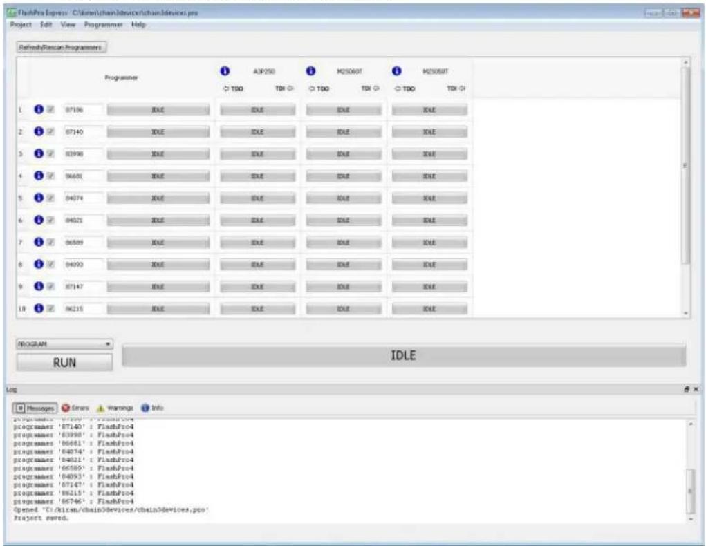
Figure 9 · FlashPro Express with Loaded Job Project (JTAG example)

Figure 10 · FlashPro Express with Loaded Job Project (SPI Slave example – SmartFusion2/IGLOO2 only) See the Export Programming Job topic for information on how to generate a Programming Job file.
- Click the Refresh/Rescan button if your programmer is not listed. Hover your mouse over the Info icon to view device info. If a device is Disabled for programming the HighZ status appears in the GUI, as shown in the figure above.
- Set the Programming Action in the dropdown menu to PROGRAM, as shown in the figure below.

Figure 11 · Programming Action Set to PROGRAM
- Click RUN. Detailed individual programmer and device status information appears in the Programmer List. Your programmer status (PASSED or FAILED) appears in the Programmer Status Bar, as shown in the figure below.
• Hover over the Programmer Status Bar to display information on the programmers.
• Hover over the FAILED status to list all programmers that failed programming.
• Hover over the PASSED status to list all the programmers that programmed successfully.

Figure 12 · Chain Programming Complete
View the Log for Messages, Errors, Warnings and Info generated during programming.
Programmer Settings and Operations
Introduction
The FlashPro Express software enables you to connect multiple programmers to your computer. With each programmer you select, you can connect the programmer, perform a self-test, customize, add, and remove and analyze the JTAG chain, as shown in the figure below.
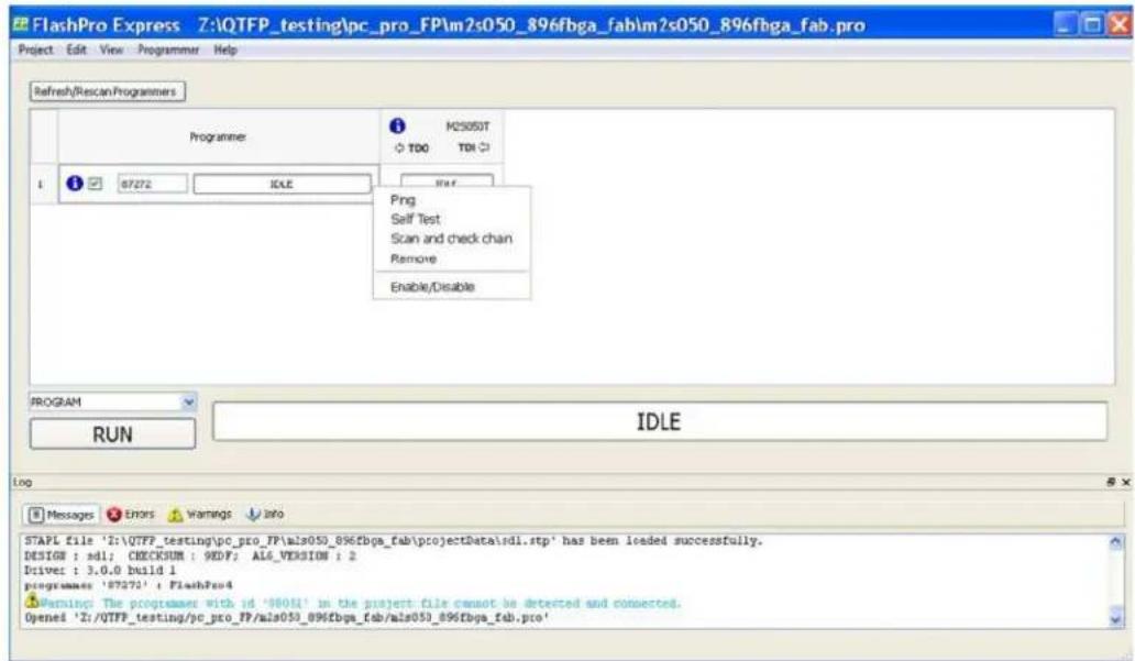
Figure 13 · FlashPro Express Right-Click Menu
Programmer Settings
In the Libero SoC Design Flow window, expand Configure Hardware, double-click Configure Programmer, or right-click Configure Programmer and choose Programmer Settings to view the Programmer Settings dialog. For the JTAG interface, you can set specific voltage and force TCK frequency values for your programmer in this dialog. For the SPI Slave interface, you can set specific voltage and force SCK frequency values for your programmer. SPI Slave mode is supported by FlashPro5 for SmartFusion2 and IGLOO2 devices, and by FlashPro6 for SmartFusion2, IGLOO2, and PolarFire devices. SPI Slave mode is not supported for RTG4 devices. JTAG is the default interface.

Figure 14 · Programmer Settings
The Programmer Settings dialog includes setting options for FlashPro6/5/4/3/3X.
Limitation of the TCK frequency for the selected programmer:
• FlashPro6: 1, 2, 3, 4, 5, 6, 7, 8, 9, 10, 11, 12, 13, 14, 15, 16, 17, 18, 19, 20 MHz
• FlashPro5: 1, 2, 3, 4, 5, 6, 10, 15, 30 MHz
• FlashPro4: 1, 2, 3, 4, 5, 6 MHz
• FlashPro3/3X: 1, 2, 3, 4, 6 MHz
TCK frequency limits by target device:
• Refer to target device data sheet
During execution, the frequency set by the FREQUENCY statement in the PDB/STAPL file overrides the TCK frequency setting selected by you in the Programmer Settings dialog box unless you also select the Force TCK Frequency checkbox.
Limitation of the SCK frequency for the selected programmer: 1.00, 2.00, 2.50, 3.33, 4.00, 5.00, 6.67, 8.00, 10.00, 13.33, 20.00 MHz
FlashPro5/4/3/3X Programmer Settings
For FlashPro5/4/3/3X, if you choose the Force TCK Frequency, select the appropriate MHz frequency. For FlashPro4/3X settings, you can switch the TCK mode between Free running clock and Discrete clocking. Discrete clocking should be used when there is a JTAG non-compliant device in a chain with Microsemi devices. After you have made your selections(s), click OK.
Default Settings
- The Force TCK Frequency option is unchecked to instruct the FlashPro5/4/3/3X to use the TCK frequency specified by the Frequency statement in the PDB/STAPL file(s).
- FlashPro5/4/3/3X default TCK mode setting is Free running clock.
TCK Setting (Force TCK Frequency)
If Force TCK Frequency is checked (in the Programmer Setting), the selected TCK value is set for the programmer and the Frequency statement in the PDB/STAPL file is ignored.
Default TCK frequency
When the IPD/STAPL file or Chain does not exist, the default TCK frequency is set to 4MHz. When more than one Microsemi flash device is targeted in the chain, the FlashPro Express software passes through all of the files and searches for the "freq" keyword and the "MAX_FREQ" Note field. The FlashPro Express software uses the lesser value of all the TCK frequency settings and the "MAX_FREQ" Note field values.
Ping Programmers
Right-click a programmer and choose Ping.
Note: You can click the Refresh/Rescan for Programmers button to quickly ping new programmers.
Performing a Self-Test
Right-click the programmer you want to self-test and choose Self Test.
Note: You must connect the programmer to the self-test board that comes with your programmer before performing a self-test.
Note: Self-test is not supported with FlashPro5/4 programmers. These programmers are rigorously tested at the factory during production.
Scanning and Checking a Chain
The scan chain operation scans and analyzes the JTAG chain connected to programmer(s) you have selected and checks that chain scanned matches the chain configured in FlashPro Express.
To scan a chain:
Right-click the programmer you want to scan and choose Scan and check chain.
Enabling and Disabling Programmers
After loading a job project, you can enable/disable or remove a programmer and can also ping, self-test, run scan and check chain on any of the connected programmers. These actions are available in the shortcut menu (right-click) for each of the programmers listed in the programmer column.
Click the checkbox next to a programmer in the Programmer column to enable or disable it. The programmer is enabled when there is a tick mark in the checkbox and disabled when the checkbox is empty.
Renaming a Programmer
Enter the new programmer name in the Programmer window to rename the programmer. By default, the programmer name is the same as the programmer ID.
Removing a Programmer
Right-click the programmer and choose Remove.
Selecting and Running an Action
FlashPro Express supports the following programming actions:
- DEVICE_INFO
• ENC DATA AUTHENTICATION
This action is only visible if every device in the chain contains encrypted bitstream files. Selecting this action causes each bitstream file to be checked for authentication. - ERASE
- PROGRAM
- READ_IDCODE
- VERIFY
To select a programming action:
Select an action from the Programming Action dropdown menu in FlashPro Express, as shown in the figure below.

Figure 15 · FlashPro Express Programming Actions
To run the selected programming action:
Click on the RUN button below the Programming Action drop-down menu.
Chain Programming
Chain Order
Chain Programming enables you to program several devices at one time. The order of devices in the chain imported from Job Project must match the physical chain to be programmed.
The TDO for the first device connects to the programmer, and the last device's TDI connects to the programmer. The devices in the chain go in order from a device's TDI into the next device's TDO, as shown in the figure below.

Figure 16 · Chain Order
Multiple Device Chain Programming
The FlashPro Express software enables direct chain programming without generating a chain STAPL file. Each device will be programmed in sequential order starting from device 1 to device N. See example below. For more information about chain order, see the Chain Order help topic.
TDI > Device N > Device N-1 >... > Device 2 > Device 1 > TDO
Device Programming Compatibility
PolarFire, SmartFusion2, IGLOO2, and RTG4 devices can be programmed in the same chain.
Programmer Support
FlashPro5/4/3/3X supports PolarFire, SmartFusion2, IGLOO2, and RTG4 devices. The Vpump on FlashPro5/4/3/3X is designed to support the programming of only one device. Make sure that Vpump, Vcc, and Vjtag are provided on board for chain programming. Connect the Vpump to the header as the Flashpro Express software will attempt to check for all external supplies, including Vpump, to ensure successful programming. There is no limitation to the chain length; however, ensure that the JTAG signal integrity and the timing are preserved.
FlashPro Express Modes
Starting with Libero SoC v12.5, FlashPro Express supports two modes: operator mode and developer mode. Operator mode is a current flow that provides production programming. It is the default mode.
Developer mode allows to update jobs before running programming. It allows to enable/disable chain devices; load design and SPI Flash Programming files and select different programming actions for each chain devices and SPI-Flash. Like operator mode, developer mode also allows you to run selected actions for all devices. Developer mode also allows you to run actions selected for each device.
The Operator or Developer mode can be selected through the Preference dialog (Project > Preferences). The preference is saved per user per machine on Windows and per user on Linux. The mode preference remains the same until the user changes it.

Figure 17 · FlashPro Express Mode Preference Dialog (Windows)

Figure 18 · FlashPro Express Mode Preference Dialog (Linux)
The FlashPro Express mode can be switched before opening a job. And, if there is a job opened, the user will be prompted to confirm closing of the job to save the mode preference, when the user clicks the "OK" button.
After a job is opened in developer mode, each device displays:
a) An info (i) icon with device specific data.
b) Design icon () ☐ . the per-device selected action is displayed next to the icon, if "Run selected action for all devices" option is unselected
c) SPI Flash icon (☐) if SPI Flash programming is available for the device. the per-device selected SPI Flash action is displayed next to the icon, if the "Run selected action for all devices" option is unselected
d) Configure button (☑) providing a menu of configuration options based on the device. The configure button is enabled when no programming action is running.
Developer mode features:
1. Device configure options

Figure 19 · Device Options to Program Design

Figure 20 · Device Options to Program Design and SPI Flash
1.1 Enable/Disable device for programming
The option allows the device to be enabled or disabled (put in "bypass").
The user must load the programming file when enabling a device that is currently in "bypass", with no programming file associated with the device or SPI-Flash. As a result, the device header info tooltip is updated with selected programming action, if enabled, or "bypass", if disabled.
Notes:
- The job cannot be saved if there is all devices are disabled or if any of enabled devices does not have loaded programming file.
- If all the devices are disabled an actions combo box and a "run" button are disabled.
1.2 Load Programming File
The option is available for the enabled devices to load a different programming file for the target device. FlashPro Express requires all programming files to be in the local job folder. When loading a programming file from outside the job folder the file will be copied to the job folder first and then loaded for the selected device. The user must confirm copying the programming file to the job folder and overwriting the existing file.
1.3 Select a programming action and configure actions and procedures per device
The option allows the selection of the programming action and configuration of the actions' procedures. The option is available for an enabled device that has programming file loaded, and when the "Run selected action for all devices" option is unselected.
1.4 Load SPI Flash file
This option allows the user to load a different SPI Flash programming file.
1.5 Select SPI Flash Action
The option allows the selection of the programming action for the SPI Flash. The option is available for the enabled device that has SPI Flash Programming File loaded, and when the "Run selected action for all devices" option is unselected.
2. Program device selected actions
In developer mode, when the "Run selected action for all devices" checkbox is selected, FlashPro Express runs selected action from the dropdown list below the checkbox for all enabled devices – similar to the Operator mode.

Figure 21 · Run One Action for All Chain Devices
When the Run selected action for all devices" checkbox is unselected, the actions dropdown list is disabled. And, FlashPro Express runs the programming actions for the enabled device and SPI Flash, as selected uniquely for each device.

Figure 22 · Run Device Selected Actions
TCL Commands - FlashPro Express
About TCL Commands - FlashPro Express Tcl Command Reference
Note: For details about all Tcl commands supported by FlashPro Express, see the Tcl Command
Reference Guide (SmartFusion2, IGLOO2, RTG4) and Tcl Command Reference Guide (PolarFire).
A Tcl (Tool Command Language) file contains scripts for simple or complex tasks. You can run scripts from the Windows command line or store and run a series of Tcl commands in a *.tcl batch file.
Note: Tcl commands are case sensitive. However, their arguments are not.
Running Tcl Scripts from within FlashPro Express
Instead of running scripts from the command line, you can use FlashPro Express's Execute Script dialog box to run a script.
To execute a Tcl script file within FlashPro Express:
- From the File menu, choose Execute Script to display the Run Script dialog box.
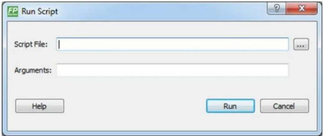
Figure 23 · Run Script Dialog Box
- Click the Browse button to display the Open dialog box, in which you can navigate to the folder containing the script file to open. When you click Open, FlashPro Express enters the full path and script filename into the Run Script dialog box for you.
- In the Arguments box, enter the arguments to pass to your Tcl script. Separate each argument by a space character. For information about accessing arguments passed to a Tcl script, see Running Tcl Scripts From the Command Line.
- Click Run.
Running Tcl Scripts from the Command Line
You can run Tcl scripts from your Windows or Linux command line.
To execute a Tcl script file in the FlashPro Express software from a shell command line:
- At the prompt, type the path to the Microsemi software followed by the word "SCRIPT" and a colon, and then the name of the script file as follows:
<location of Microsemi software>/bin/FPExpress.exe SCRIPT:<filename>
The example below executes in batch mode the script foo.tcl:
<location of Microsemi software>/bin/FPExpress.exe script:foo.tcl
The example below executes in batch mode the script foo.tcl and exports the log in the file foo.txt.
<location of Microsemi software>/bin/FPExpress.exe script:foo.tcl logfile:foo.txt
The example below executes in batch mode the script foo.tcl, creates a console where the log is displayed briefly, and exports the log in the file foo.txt:
<location of Microsemi software>/bin/FPExpress.exe script:foo.tclconsole_mode:brief
logfile:foo.txt
If you leave console_mode unspecified or set it to 'hide' FlashPro Express executes without a console window. If you want to leave the console window open you can run the script with the console_mode parameter set to 'show', as in the following example:
<location of Microsemi software>/bin/FPExpress.exe script:foo.tclconsole_mode:show
logfile:foo.txt
- If you want to pass arguments to the Tcl script from the command line, then use the "SCRIPT_ARGS" variable as follows:
<location of Microsemi software>/bin/FPExpress.exe SCRIPT:<filename>SCRIPT_ARGS:"param1 param2 param3"
Arguments passed to a Tcl script can be accessed through the Tcl variables argc and argv. The example below demonstrates how a Tcl script accesses these arguments:
puts "Script name: $argv0"
puts "Number of arguments: $argc"
set i 0
foreach arg $argv {
    puts "Arg i :arg"
    incr i
}
Note: Script names can contain spaces if the script name is protected with double quotes:
FPExpress script:"FPExpress tcl/foo 1.tcl"
Exporting Tcl Scripts from within FlashPro Express
To export a set of Tcl commands from the FlashPro Express history:
- From the File menu, choose Export Script File.
- Enter the filename and click Save. The Export Script Options dialog appears (as shown in the figure below).
![Export Script Script file: [exported.td] Files name formatting Relative file names (relative to the script file location) Qualified file names (full path; including directory name) Help OK Cancel](/content/2026/07/1415041/images/093cc35bec8d8eeadbf42bede8b34881be9699d61dba0428613325fa5ad5bcd1.jpg)
Figure 24 · Script Export Options Dialog Box
- Check the Include commands from current project only to export commands of the current project only. You can specify the filename formatting by selecting Relative filenames (relative to the current directory) or Qualified filenames (absolute path, including the directory name).
- Click OK.
Troubleshooting
Exit Codes (PolarFire)
| Error Code | Exit Message Exit Code | Possible Cause | Possible Solution |
| Passed (no error) | 0 | - | |
| 0x8002 | Failed to disable programming modeFailed to set programming mode | 5 Unstable voltage levelSignal integrity issues on JTAG pins | Monitor related power supplies that cause the issue during programming; check for transients outside of Microsemi specifications. See your device datasheet for more information on transient specifications.Monitor JTAG supply pins during programming; measure JTAG signals for noise or reflection. |
| 0x8032 Device is busy | 5 | Unstable VDDlx voltage level | Monitor related power supplies that cause the issue during programming; check for transients outside of Microsemi specifications. See your device datasheet for more information on transient specifications. |
| 0x8003 | Failed to enter programming mode | 5 Unstable voltage levelSignal integrity issues on JTAG pinsDEVRST_N is tied to LOW | Monitor related power supplies that cause the issue during programming; check for transients outside of Microsemi specifications. See your device datasheet for more information on transient specifications.Monitor JTAG supply pins during programming; measure JTAG signals for noise or reflection.Tie DEVRST_N to HIGH prior to programming the device. |
| 0x8004 Failed to verify IDCODE | 6 Incorrect programming fileIncorrect device in chainSignal integrity issues on JTAG pins | Choose the correct programming file and select the correct device in the chain.Measure JTAG pins and noise for reflection. If TRST is left floating then add pull-up to pin.Reduce the length of Ground connection. | |
| 0x8005 0x8006 0x8007 0x8008 | Failed to verify FPGA ArrayFailed to verify Fabric ConfigurationFailed to verify Security | 11 Device is programmed with a different design or the component is blank.Unstable voltage level.Signal integrity issues on JTAG pins. | Verify the device is programmed with the correct data/design.Monitor related power supplies that cause the issue during programming; check for transients outside of Microsemi specifications. See your device datasheet for more information on transient specifications. |
| Error Code | Exit Message | Exit Code | Possible Cause | Possible Solution |
| Failed to verify sNVM | Monitor JTAG supply pins during programming; measure JTAG signals for noise or reflection. | |||
| 0x8013 | External digest check via JTAG/SPI Slave is disabled. | -18 | External Digest check via JTAG/SPI Slave is disabled. | Need to use a bitstream file which has a valid FlashLock/UPK1 to enable external digest check via JTAG/SPI Slave. |
| 0x8015 | FPGA Fabric digest verification: FAILDeselect procedure 'DO_ENABLE_FABRIC' to remove this digest check. | -20 | FPGA Fabric is either erased or the data has been corrupted or tampered with | If the Fabric is erased, deselect procedure "DO_ENABLE_FABRIC" from action "VERIFY_DIGEST" |
| 0x8016 | sNVM digest verification: FAILDeselect procedure 'DO_ENABLE_SNVM' to remove this digest check. | -20 | sNVM is either erased or the data has been corrupted or tampered with | If the sNVM is erased, deselect procedure "DO_ENABLE_SNVM" from action "VERIFY_DIGEST" |
| 0x8018 | User security policies segment digest verification: FAILDeselect procedure 'DO_ENABLE_SECURITY' to remove this digest check. | -20 | Security segment is either erased or the data has been corrupted or tampered with | If the security is erased, deselect procedure "DO_ENABLE_SECURITY" from action "VERIFY_DIGEST" |
| 0x8019 | UPK1 segment digest verification: FAILDeselect procedure 'DO_ENABLE_SECURITY' to remove this digest check. | -20 | UPK1 segment is either erased or the data has been corrupted or tampered with | If the UPK1 is erased, deselect procedure "DO_ENABLE_SECURITY" from action "VERIFY_DIGEST" |
| 0x801A | UPK2 segment digest verification: FAILDeselect procedure 'DO_ENABLE_UKS2' to remove this digest check. | -20 | UPK2 segment is either erased or the data has been corrupted or tampered with | If the UPK2 is erased, deselect procedure "DO_ENABLE_UKS2" from action "VERIFY_DIGEST" |
| 0x801B | Factory row and factory key segment digest verification: FAIL | -20 | Factory row and factory key segment have been erased through zeroization or the data has been corrupted or tampered with | |
| 0x801C Fabric configuration segment digest verification: FAILDeselect procedure 'DO_ENABLE_FABRIC' to remove this digest check. | -20 Fabric configuration segment is either erased or has been corrupted or tampered with | If the Fabric configuration is erased, deselect procedure "DO_ENABLE_FABRIC" from action "VERIFY_DIGEST" | ||
| 0x8052 UEK1 segment digest verification: FAILDeselect procedure 'DO_ENABLE_UEK1' to remove this digest check. | -20 | UEK1 segment is either erased or the data has been corrupted or tampered with | If the UEK1 is erased, deselect procedure "DO_ENABLE_UEK1" from action "VERIFY_DIGEST" | |
| 0x8053 | UEK2 segment digest verification: FAILDeselect procedure 'DO_ENABLE_UEK2' to remove this digest check. | -20 | UEK2 segment is either erased or the data has been corrupted or tampered with | If the UEK2 is erased, deselect procedure "DO_ENABLE_UEK2" from action "VERIFY_DIGEST" |
| 0x8054 | DPK segment digest verification: FAILDeselect procedure 'DO_ENABLE_DPK' to remove this digest check. | -20 | DPK segment is either erased or the data has been corrupted or tampered with | If the DPK is erased, deselect procedure "DO_ENABLE_DPK" from action "VERIFY_DIGEST" |
| 0x8057 SMK segment digest verification: FAIL | -20 SMK segment is either erased or the data has been corrupted or tampered with | If the SMK is erased, deselect procedure "DO_ENABLE_SMK" from action "VERIFY_DIGEST" | ||
| 0x8058 | User Public Key segment digest verification: FAIL | -20 | User Public Key segment is either erased or the data has been corrupted or tampered with | If the User Public Key is erased, deselect procedure "DO_ENABLE_USER_PUBLIC_KEY" from action "VERIFY_DIGEST" |
| 0x801D Device security prevented operation | -21 The device is protected with user pass key 1 and the bitstream file does not contain user pass key 1.User pass key 1 in the bitstream file does not match the device. | Run DEVICE_INFO to view security features that are protected.Provide a bitstream file with a user pass key 1 that matches the user pass key 1 programmed into the device. | ||
| 0x801F | Programming Error.Bitstream or data is corrupted or noisy | -22 | Bitstream file has been corrupted or was incorrectly generated.Unstable voltage level.Signal integrity issues on JTAG pins. | Regenerate bitstream fileMonitor related power supplies that cause theissue during programming; check for transients outside of Microsemi specifications. See your device datasheet for more information on transient specifications.Monitor JTAG supply pins during programming; measure JTAG signals for noise or reflection. |
| 0x8021 Programming Error.Invalid/Corrupted encryption key | -23 File | contains an encrypted key that does not match the deviceFile contains user encryption key, but device has not been programmed with the user encryption key | Provide a programming file with an encryption key that matches that on the deviceFirst program security with master programming file, then program with user encryption 1/2 field update programming files | |
| 0x8023 Programming Error.Back level not satisfied | -24 Design version is not higher than the back-level programmed device | Generate a programming file with a design version higher than the back level version | ||
| 0x8001 | Failure to read DSN | -24 | Device is in System Controller Suspend ModeCheck board connections | TRSTB should be driven High or disable "System Controller Suspend Mode". |
| 0x8027 Programming Error.Insufficient device capabilities | -26 Device does not support the capabilities specified in programming file | Generate a programming file with the correct capabilities for the target device | ||
| 0x8029 | Programming Error.Incorrect DEVICEID | -27 Incorrect programming fileIncorrect device in chainSignal integrity issues on JTAG pins | Choose the correct programming file and select the correct device in chainMeasure JTAG pins and noise or reflection. If TRST is left floating, then add pull-up to pinReduce the length of ground connection | |
| 0x802B Programming Error.Programming file is out of date, please regenerate. | -28 | Programming file version is out of date | Generate programming file with latest version of Libero SoC | |
| 0x8030 Programming ErrorInvalid or inaccessible Device Certificate | -31 FAB_RESET_N is tied to ground | FAB_RESET_N should be tied to HIGH | ||
| 0x80320x80340x80360x8038 | Instruction timed out | -32 | Unstable voltage levelSignal integrity issues on JTAG pins | Monitor related power supplies that cause the issue during programming; check for transients outside of Microsemi specifications. See your device datasheet for more information on transient specifications.Monitor JTAG supply pins during programming; measure JTAG signals for noise or reflection. |
| 0x8010 Failed to unlock user pass key 1 | -35 Pass key in file does not match device | Provide a programming file with a pass key that matches pass key programmed into the device. | ||
| 0x8011 | Failed to unlock user pass key 2 | -35 | Pass key in file does not match device | Provide a programming file with a pass key that matches pass key programmed into the device. |
| 0x804F | Bitstream programming action is disabled | -38 Unstable voltage levelBitstream programming action has been disabled in Security Policy Manager | Monitor related power supplies that cause the issue during programming; check for transients outside of Microsemi specifications. See your device datasheet for more information on transient specifications.Need to use a bitstream file which has a valid FlashLock/UPK1 to enable the bitstream programming action. | |
| 0x805B | Error, security must be either programmed on a blank device or with the FPGA Fabric design | -42 | Security only bitstream programming on a programmed device | Use this bitstream on a blank device or generate a new bitstream that contains the FPGA Fabric design along with the security |
Exit Codes (RTG4)
| Error Code | Exit Message | Possible Cause | Possible Solution |
| Passed (no error) | - | - | |
| 0x8001 | Failure to read DSN Device is in System Controller Suspend Mode Check board connections | TRSTB should be driven High on device power up. Disable System Controller Suspend Mode in "Programming Bitstream Settings' tool within Libero and reprogram the device. | |
| 0x8002 | Device is busy | Unstable VDDIx voltage level | Monitor related power supplies that cause the issue during programming; check for transients outside of Microsemi specifications. See your device datasheet for more information on transient specifications. |
| 0x8003 Failed to enter programming mode | Unstable voltage level Signal integrity issues on | Monitor related power supplies that cause the issue during programming; check for transients | |
| JTAG pinsDEVRST_N is tied to LOW | outside of Microsemi specifications. See your device datasheet for more information on transient specifications.Monitor JTAG supply pins during programming; measure JTAG signals for noise or reflection.Tie DEVRST_N to HIGH prior to programming the device | ||
| 0x8004 | Failed to verify IDCODE | Incorrect programming fileIncorrect device in chainSignal integrityissues on JTAG pins | Choose the correct programming file and select the correct device in the chain.Measure JTAG pins and noise for reflection. If TRST is left floating then add pull-up to pin.Reduce the length of Ground connection. |
| 0x8005 | Failed to verify IDCODERT4G150_ESSTAPL file is not compatible with RT4G150 production devices. You must use a STAPL file for RT4G150 device. | Programming file is for RT4G150_ES and device is RT4G150Incorrect programming fileIncorrect device in chainSignal integrityissues on JTAG pins | Generate a programming file for RT4G150 deviceChoose the correct programming file and select the correct device in the chain.Measure JTAG pins and noise for reflection. If TRST is left floating then add pull-up to pin.Reduce the length of Ground connection. |
| 0x8006 Failed to | verify IDCODERT4G150STAPL file is not compatible with RT4G150_ES devices. You must use a STAPL file for RT4G150_ES device. | Programming file is for RT4G150 and device isRT4G150_ESIncorrect programming fileIncorrect device in chainSignal integrityissues on JTAG pins | Generate a programming file for RT4G150_ES deviceChoose the correct programming file and select the correct device in the chain.Measure JTAG pins and noise for reflection. If TRST is left floating then add pull-up to pin.Reduce the length of Ground connection. |
| 0x8007 Failed to | verify FPGAArray | Device is programmed with a different design or the component is blank.Unstable voltage level.Signal integrityissues on JTAG pins. | Verify the device is programmed with the correct data/design.Monitor related power supplies that cause the issue during programming; check for transients outside of Microsemi specifications. See your devicedatasheet for more information on transient specifications.Monitor JTAG supply pins during programming; measure JTAG signals for noise or reflection. |
| 0x8008 | Device is blank | Attempting to verify digest of a blank device | Program the device prior to running action "VERIFY_DIGEST" |
| 0x8009 | FPGA array digest check is disabled | Digest check has been disabled by "Programming Bitstream Settings" tool within Libero | Drive TRSTB high during device power up.Enable digest check in "Programming Bitstream Settings" tool within Libero and reprogram the device. |
| 0x800A Failed to | verify digest: Instruction timed out | Unstable voltage level Signal integrity issues on JTAG pins | Try running VERIFY_DIGEST action again.Monitor related power supplies that cause the issue during programming; check for transients outside of Microsemi specifications. See your device datasheet for more information on transient specifications.Monitor JTAG supply pins during programming; measure JTAG signals for noise or reflection. |
| 0x800B | FPGA Fabric digest verification: FAIL | Programming bitstream components do not match components programmedFPGA Fabric is either erased or the data has been corrupted or tampered with | Use the same programming file that was used to program the device. |
| 0x800C Factory row segment digest verification: FAIL | Programming bitstream components do not match components programmedFactory row segment data has been corrupted or tampered with | Use the same programming file that was used to program the device. | |
| 0x800D | Bitstream Error.Bitstream or data is corrupted or noisy. | Bitstream file has been corruptedBitstream was incorrectly generatedUnstable voltage levelSignal integrityissues on JTAG pins | Regenerate bitstream fileMonitor related power supplies that cause the issue during programming; check for transients outside of Microsemi specifications. See your device datasheet for more information on transient specifications.Monitor JTAG supply pins during programming; measure JTAG signals for noise or reflection. |
| 0x800E | Failed to query programming bitstream settings: Instruction timed out | Unstable voltage levelSignal integrityissues on JTAG pins | Try running DEVICE_INFO action again.Monitor related power supplies that cause the issue during programming; check for transients outside of Microsemi specifications. See your device datasheet for more information on transient specifications.Monitor JTAG supply pins during programming; measure JTAG signals for noise or reflection. |
| 0x800F | Bitstream Error. Incorrect DEVICEID | Incorrect programming fileIncorrect device in chainSignal integrityissues on JTAG pins | Choose the correct programming file and select the correct device in the chain.Measure JTAG pins and noise for reflection. If TRST is left floating then add pull-up to pin.Reduce the length of Ground connection. |
| 0x8010 | Operation has been disabled by programming bitstream settings | Operation has been disabled by"Programming Bitstream Settings" tool within LiberoUser disabled Fabric Erase/Write/Verify and attempted to Erase/Program/Verify the device | Drive TRSTB high during device power upEnable the disabled operation in the "Programming Bitstream Settings" tool with Libero and reprogram the device |
| 0x8011 Failed to check bitstream: Instruction timed out | Unstable voltage level Signal integrity issues on JTAG pins | Monitor related power supplies that cause the issue during programming; check for transients outside of Microsemi specifications. See your device datasheet for more information on transient specifications.Monitor JTAG supply pins during programming; measure JTAG signals for noise or reflection. | |
| 0x8012, 0x8013 | Failed to erase device: Instruction timed out | Unstable voltage level Signal integrity issues on JTAG pins | Monitor related power supplies that cause the issue during programming; check for transients outside of Microsemi specifications. See your device datasheet for more information on transient specifications.Monitor JTAG supply pins during programming; measure JTAG signals for noise or reflection. |
| 0x8014 | Failed to program device: Instruction timed out | Unstable voltage level Signal integrity issues on JTAG pins | Monitor related power supplies that cause the issue during programming; check for transients outside of Microsemi specifications. See your device datasheet for more information on transient specifications.Monitor JTAG supply pins during programming; measure JTAG signals for noise or reflection. |
| 0x8015 Error, device is not ready. | DEVRST_N may have been driven LOW during programming | Need to ensure that DEVRST_N is driven HIGH during programming. The reliability of the device in space cannot be guaranteed if this has occurred. It is the user's responsibility to ensure that DEVRST_N is driven HIGH during programming. | |
Exit Codes (SmartFusion2 and IGLOO2)
| Error Code | Exit Code | Exit Message | Possible Cause | Possible Solution |
| 0 Passed (no error) | - | - | ||
| 0x8002 | 5 | Failure to configure device programming at 1.2/1.0 VCC voltage | Unstable voltage levelSignal integrity issues on JTAG pins | Monitor related power supplies that cause the issue during programming; check for transients outside of Microsemi specifications. See your device datasheet for more information on transient specifications.Monitor JTAG supply pins during programming; measure JTAG signals for noise or reflection. |
| 0x8032 | 5 | Device is busy | Unstable VDDlx voltage level | Monitor related power supplies that cause the issue during programming; check for transients outside of Microsemi specifications. See your device datasheet for more information on transient specifications. |
| 0x8003 | 5 Failed to enter programming mode | Unstable voltage levelSignal integrity issues on JTAG pinsDEVRST_N is tied to LOW | Monitor related power supplies that cause the issue during programming; check for transients outside of Microsemi specifications. See your device datasheet for more information on transient specifications.Monitor JTAG supply pins during programming; measure JTAG signals for noise or reflection.Tie DEVRST_N to HIGH prior to programming the device. | |
| 0x8004 | 6 | Failed to verify IDCODE | Incorrect programming fileIncorrect device in chainSignal integrity issues on JTAG pins | Choose the correct programming file and select the correct device in the chain.Measure JTAG pins and noise for reflection. If TRST is left floating then add pull-up to pin.Reduce the length of Ground connection. |
| 0x80050x80068x804A | 10 | Failed to program eNVM | Unstable voltage level.Signal integrity issues on JTAG pins. | Monitor related power supplies that cause the issue during programming; check for transients outside of Microsemi specifications. See your device datasheet for more information on transient specifications.Monitor JTAG supply pins during programming; measure JTAG signals for noise or reflection. |
| 0x80270x8028 | 10 Authentication ErrorBitstream and device mismatch | Libero device selection does not match the target device. | Generate a programming file with the correct device selection for the target device. | |
| 0x80070x804C | 11 Failed to verify FPGA ArrayFailed to verify Fabric ConfigurationFailed to verify Security | Device is programmed with a different design or the component is blank.Unstable voltage level.Signal integrity issues on JTAG pins. | Verify the device is programmed with the correct data/design.Monitor related power supplies that cause the issue during programming; check for transients outside of Microsemi specifications. See your device datasheet for more information on transient specifications.Monitor JTAG supply pins during programming; measure JTAG signals for noise or reflection. | |
| 0x80080x80090x8049 | 11 | Failed to verify eNVM | Device is programmed with a different design.Unstable voltage level.Signal integrity issues on JTAG pins. | Verify the device is programmed with the correct data/design.Monitor related power supplies that cause the issue during programming; check for transients outside of Microsemi specifications. See your device datasheet for more information on transient specifications.Monitor JTAG supply pins during programming; measure JTAG signals for noise or reflection. |
| 0x8013 -18 | Digest request from SPI/JTAG is protected by User Pass Key 1 | Digest request from SPI/JTAG is protected by user pass key 1. Lock bit has been configured in the Debug Policy within SPM (Security Policy Manager) | Provide a programming file with a pass key that matches pass key programmed into the device. | |
| 0x8014 | -19 | Failed to verify digest | >Unstable voltage levelSignal integrity issues on JTAG pins | Monitor related power supplies that cause the issue during programming; check for transients outside of Microsemi specifications. See your device datasheet for more information on transient specifications.Monitor JTAG supply pins during programming; measure JTAG signals for noise or reflection. |
| 0x8015 -20 | FPGA | Fabric digest verification: FAIL | Programming bitstream components do not match components programmedFPGA Fabric is either erased or the data has been corrupted or tampered with | Use the same programming file that was used to program the device. |
| 0x8016 -20 | eNVM_ | 0 digest verification: FAIL | Programming bitstream components do not match components programmedeNVM_0 data has been corrupted or tampered with | Use the same programming file that was used to program the device. |
| 0x8017 -20 | eNVM_ | 1 digest verification: FAIL | Programming bitstream components do not match components programmedeNVM_1 data has been corrupted or tampered with | Use the same programming file that was used to program the device. |
| 0x8018 | -20 | User security policies segment digest verification: FAIL | Programming bitstream components do not match components programmedUser security policy segment data has been corrupted or tampered with | Use the same programming file that was used to program the device. |
| 0x8019 -20 | User key set 1 segment digest verification: FAIL | Programming bitstream components do not match components programmedUser key set 1 segment data has been corrupted or tampered with | Use the same programming file that was used to program the device. | |
| 0x801A | -20 | User key set 2 segment digest verification: FAIL | Programming bitstream components do not match components programmedUser key set 2 segment data has been corrupted or tampered with | Use the same programming file that was used to program the device. |
| 0x801B -20 | Factory row and factory key segment digest verification: FAIL | Programming bitstream components do not match components programmedFactory row and factory key segment data has been corrupted or tampered with | Use the same programming file that was used to program the device. | |
| 0x801C -20 Fabric | configuration segment digest verification: FAIL | Programming bitstream components do not match components programmed.Fabric configuration segment data has been corrupted or tampered with | Use the same programming file that was used to program the device. | |
| 0x801D 0x801E 0x804B | -21 | Device security prevented operation | The device is protected with user pass key 1 and the bitstream file does not contain user pass key 1.User pass key 1 in the bitstream file does not match the device. | Run DEVICE_INFO to view security features that are protected.Provide a bitstream file with a user pass key 1 that matches the user pass key 1 programmed into the device. |
| 0x801F 0x8020 0x8040 | -22 Authentication ErrorBitstream or data is corrupted or noisy | eNVM has been locked by a master in your designRunning VERIFY action on a blank device.Bitstream file has been corruptedBitstream was incorrectly generated | Release the lock on the eNVM after your master has completed its access operations. Write 0x00 to "REQACCESS" register in eNVM Control Registers (address 0x600801FC) to release the access,Program the device prior to running VERIFY actionRegenerate bitstream file. | |
| 0x8021 0x8022 | -23 Authentication ErrorInvalid/Corrupted encryption key | File contains an encrypted key that does not match the deviceAttempting to erase a device with no security using master security fileFile contains user encryption key, but device has not been programmed with the user encryption keyDevice has user encryption key 1/2 enforced and you are attempting to reprogram security settings | Provide a programming file with an encryption key that matches that on the device.Run DEVICE_INFO action to verify that the device has no security. If the device does not have security, you cannot erase it.First program security with master programming file, then program with user encryption 1/2 field update programming files.You must first ERASE security with the master security file, then you can reprogram new security settings. | |
| 0x8041 | -23 | Authentication ErrorInvalid/Corrupted encryption key | File contains an encrypted key that does not match the deviceFile contains user encryption key, but device has not been programmed with the user encryption keyAttempting to erase a device with no security using master security fileDevice has user encryption key 1/2 enforced and you are attempting to reprogram security settings | Provide a programming file with an encryption key that matches that on the device.Run DEVICE_INFO action to verify that the device has no security. If the device does not have security, you cannot erase it.First program security with master programming file, then program with user encryption 1/2 field update programming files.You must first ERASE security with the master security file, then you can reprogram new security settings. |
| 0x80230x80240x8042 | -24 Authentication ErrorBack level not satisfied | Design version is not higher than the back-level programmed device | Generate a programming file with a design version higher than the back level version. | |
| 0x8001 | -24 | Failure to read DSN | Device is in System Controller Suspend ModeCheck board connections | TRSTB should be driven High or disable "System Controller Suspend Mode". |
| 0x80250x80260x8043 | -25 Authentication ErrorDSN binding mismatch | DSN specified in programming file does not match the device being programmed | Use the correct programming file with a DSN that matches the DSN of the target device being programmed. | |
| 0x8044 | -26 Authentication ErrorInsufficient device capabilities | Device does not support the capabilities specified in programming file | Generate a programming file with the correct capabilities for the target device. | |
| 0x80270x8028 | -26 Authentication ErrorBitstream and device mismatch | Libero device selection does not match the target device | Generate a programming file with the correct device selection for the target device. | |
| 0x80290x802A0x8045 | -27 | Authentication ErrorIncorrect DEVICEID | Incorrect programming fileIncorrect device in chainSignal integrity issues on JTAG pins | Choose the correct programming file and select the correct device in chain.Measure JTAG pins and noise or reflection. If TRST is left floating, then add pull-up to pin.Reduce the length of ground connection. |
| 0x802B0x802C | -28 Authentication ErrorProgramming file is out of date, please regenerate | Programming file version is out of date | Generate programming file with latest version of Libero SoC. | |
| 0x8046 | -28 | >Authentication ErrorUnsupported bitstream protocol version | Old programming file Generate | programming file with latest version of Libero SoC. |
| 0x802F -30 | JTAG interface is protected by UPK1 | Invalid or no UPK1 is provided | User needs to provide correct UPK1 to unlock device. | |
| 0x80300x80310x8048 | -31 Authentication ErrorInvalid or inaccessible Device Certificate | M2S090 Rev. A or M2S150Rev. A:Either certificate is corrupted or the user hasn't provided the application code in the eNVM or provided invalid application codeFAB_RESET_N is tied to ground | User can program a valid application code. This can be done with SoftConsole.FAB_RESET_N should be tied to HIGH. | |
| 0x80320x80330x80340x80350x80360x80370x80380x8039 | -32 | Instruction timed out | Unstable voltage levelSignal integrity issues on JTAG pins | Monitor related power supplies that cause the issue during programming; check for transients outside of Microsemi specifications. See your device datasheet for more information on transient specifications.Monitor JTAG supply pins during programming; measure JTAG signals for noise or reflection. |
| 0x8010 -35 | Failed to unlock User Pass Key 1 | Pass key in file does not match device.Plaintext pass key match is disabled. This occurs if HSM was used to program the device. | Provide a programming file with a pass key that matches pass key programmed into the device.Match pass key using HSM. | |
| 0x8011 -35 | Failed to unlock User Pass Key 2 | Pass key in file does not match device.Plaintext pass key match is disabled. This occurs if HSM was used to program the device. | Provide a programming file with a pass key that matches pass key programmed into the device.Match pass key using HSM. | |
| 0x8012 -35 | Failed to unlock debug pass key | Pass key in file does not match device.Plaintext pass key match is disabled. This occurs if HSM was used to program the device. | Provide a programming file with a pass key that matches pass key programmed into the device.Match pass key using HSM. | |
| 0x804D -36 | related error message based on scenario> | HSM communication error. HSM call returns error. | Check if HSM the communication path to HSM is up. Make sure project is loaded properly and that HSM tickets have not been cleaned. | |
| 0x804E -37 | Device | already has Security programmed. Please erase the device using master file before reprogramming Security Settings. | HSM flow does not support reprogramming device directly if Security has already been programmed. | Erase security and try programming the device. |
SmartDebug
Microsemi's SmartDebug tool complements design simulation by allowing verification and troubleshooting at the hardware level.
For detailed information about SmartDebug for SmartFusion2, IGLOO2, and RTG4, refer to the SmartDebug User Guide (SmartFusion2, IGLOO2, RTG4).
For detailed information about SmartDebug for PolarFire, refer to the SmartDebug User Guide (PolarFire).
Electrical Parameters
DC Characteristics for FlashPro6
Table 2 · DC Characteristic for FlashPro6
| Parameter | Test Condition | VJTAG Voltage Range | Min | Typ | Max | Unit |
| VIH High-level input voltage | 1.20V - 1.95V | VJTAG_VSPI x 0.65 | V | |||
| 1.95V - 2.70V 1.6 | V | |||||
| 2.70V - 3.60V | 2 | V | ||||
| VIL Low-level input voltage | 1.20V - 1.95V | VJTAG_VSPIx0.35 | V | |||
| 1.95V - 2.70V | 0.7 | V | ||||
| 2.70V - 3.60V | 0.8 | V | ||||
| VOH | IOH = -100μA | 1.2 V to 3.6 V | VJTAG_VSPI - 0.2 | V | ||
| IOH = -3mA | 1.2V | V | ||||
| IOH = -6mA | 1.4V 1.05 | V | ||||
| IOH = -8mA | 1.65V 1.2 | 0.95 | V | |||
| IOH = -9mA | 2.3V 1.75 | V | ||||
| IOH = -12mA | 3V 2.3 | V | ||||
| VOL | IOH = -100μA | 1.2 V to 3.6 V | V | |||
| IOH = -3mA | 1.2V | 0.25 | V | |||
| IOH = -6mA | 1.4V | V | ||||
| IOH = -8mA | 1.65V | V | ||||
| IOH = -9mA | 2.3V | V | ||||
| IOH = -12mA | 3V | V | ||||
| IOH High-level output current | 1.1 V to 1.2 V | -3 | mA | |||
| 1.4 V to 1.6 V | -6 | mA | ||||
| 1.65V to 1.95V | -8 | mA | ||||
| 2.3 V to 2.7 V | -9 | mA | ||||
| 3 V to 3.6 V | -12 | mA | ||||
| 1.1 V to 1.2 V | 3 | mA | ||||
| 1.4 V to 1.6 V | 6 | mA | ||||
| IOL Low-level output current | 1.65V to 1.95V | 8 | mA | |||
| 2.3 V to 2.7 V | 9 | mA | ||||
| 3 V to 3.6 V | 12 | mA |
DC Characteristics for FlashPro5/4/3/3X
Note: The target board must provide the VCC, VCCI, VPUMP, and VJTAG during programming.
Note: The VJTAG signal is driven from the target/DUT board. The VJTAG pin is sensed by the FP4 to configure the internal input and output buffers to the same IO Voltage levels. The VJTAG pin is only an input pin to the programmer.
Table 3 · DC Characteristic for FlashPro5/4/3/3X
| Description | Symbol | Min | Max | Unit |
| Input low voltage, TDO | VIL | -0.5 | 0.35*VJTAG | V |
| Input high voltage, TDO | VIH | 0.65*VJTAG | 3.6 | V |
| Input current, TDO | IIL, IIH | -20 | +20 | mA |
| Input capacitance, TDO | 40 | pF | ||
| Output voltage, VPUMP, operating | VPP | +3.0 | +3.6 | V |
| Output current, VPUMP | IPP | 250 | mA | |
| VJTAG = 1.5V | ||||
| Output low voltage, TCK, TMS, TDI, 100μA load | VOL | 0.0 | 0.2 | V |
| Output low voltage, TCK, TMS, TDI, 4mA load | VOL | 0.0 | 0.30*VJTAG | V |
| Output high voltage, TCK, TMS, TDI, 100μA load | V | VJTAG-0.2 | VJTAG | V |
| Output high voltage, TCK, TMS, TDI, 4mA load | VOH | 0.70*VJTAG | VJTAG | V |
| Output current, TCK, TMS, TDI | IOL, IOH | -4 | +4 | mA |
| VJTAG = 1.8V | ||||
| Output low voltage, TCK, TMS, TDI, 100μA load | VOL | 0.0 | 0.2 | V |
| Output low voltage, TCK, TMS, TDI, 6mA load | VOL | 0.0 | 0.3 | V |
| Output high voltage, TCK, TMS, TDI, 100μA load | VOH | VJTAG-0.2 | VJTAG | V |
| Output high voltage, TCK, TMS, TDI, 6mA load | VOH | 1.25 | VJTAG | V |
| Output current, TCK, TMS, TDI | IOL, IOH | -6 | +6 | mA |
| VJTAG = 2.5V | ||||
| Output low voltage, TCK, TMS, TDI, 100μA load | VOL | 0.0 | 0.2 | V |
| Output low voltage, TCK, TMS, TDI, 8mA load | VOL | 0.0 | 0.6 | V |
| Output high voltage, TCK, TMS, TDI, 100μA load | VOH | VJTAG-0.2 | VJTAG | V |
| Output high voltage, TCK, TMS, TDI, 8mA load | VOH | 1.8 | VJTAG | V |
| Output current, TCK, TMS, TDI | IOL, IOH | -8 | +8 | mA |
| VJTAG = 3.3V | ||||
| Output low voltage, TCK, TMS, TDI, 100μA load | VOL | 0.0 | 0.2 | V |
| Output low voltage, TCK, TMS, TDI, 8mA load | VOL | 0.0 | 0.4 | V |
| Output high voltage, TCK, TMS, TDI, 100μA load | VOH | VJTAG-0.2 | VJTAG | V |
| Output high voltage, TCK, TMS, TDI, 8mA load | VOH | 2.4 | VJTAG | V |
| Output current, TCK, TMS, TDI | IOL, IOH | -8 | +8 | mA |
Electrical Specifications
FlashPro6
The FlashPro6 is a JTAG-based programmer for flash based Microsemi devices.
The FlashPro6 output is supplied via a connector to which a detachable 10-pin cable is fitted. The connector on the FlashPro6 unit is a 2x5, RA male Header connector, which is manufactured by 3M and has a manufacturer's part number of N2510-5002-RB. This is a standard 2x5, 0.1 pitch connector which is keyed. Use the 10 pin right-angle header, 3M P/N N2510-5002-RB (DigiKey P/N MHE10K-ND) for FlashPro6 and use the 10 pin straight header,
The signals on the pins of the FlashPro6 10-pin connector are shown in the figure below.

Figure 25 · FlashPro6 10-Pin Connector
Note: All ground pins must be connected. The rectangular shape shows connections on the programmer itself. Arrows show current flow towards or from the rectangular programmer.
The table below shows a description of the signals.
Table 4 · FlashPro6 Signal Description
| Signal Description | |
| GND Signal reference | |
| TCK/SCK JTAG clock; SPI clock | |
| TDI/SDI | JTAG data input to device; SPI MOSI |
| TDO/SDO | JTAG data output from device; SPI MISO |
| TMS/SS# JTAG mode select; SPI Chip Select | |
| nTRST | Programmable output pin may be set to off, toggle, low, or high level |
| VJTAG Reference voltage from the target board | |
Some designers of high-integrity boards (military and avionic) may arrange their boards so that TRST is tied to ground via a weak pull-down resistor. The purpose of this is to hold the JTAG state-machine in a reset state by default, so that even with TCK oscillating, some sudden ion bombardment or other electrical even will not suddenly throw the JTAG state-machine into an unknown state. If your design also uses a weak pull-down resistor on TRST on your board, then enabling the "Drive TRST" flag will be required to force the JTAG state-machine out of reset to permit programming to take place. With most boards, there is no need to select this flag.
FlashPro5
The FlashPro5 is a JTAG and a SPI based programmer for flash based Microsemi devices.
The FlashPro5 output is supplied via a connector to which a detachable 10-pin cable is fitted. The connector on the FlashPro5 unit is a 2x5, RA male Header connector, which is manufactured by AMP and has a manufacturer's part number of 103310-1. This is a standard 2x5, 0.1 pitch connector which is keyed. Use the 10 pin right-angle header, AMP P/N 103310-1 (DigiKey P/N A26285-ND) for FlashPro4 and use the 10 pin straight header, AMP P/N 103308-1 (DigiKey P/N A26267-ND) for the straight version.
The signals on the pins of the FlashPro5 10-pin connector are shown in the figure below.
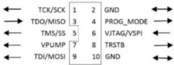
Figure 26 · FlashPro5 10-Pin Connector
Note: All ground pins must be connected. The rectangular shape shows connections on the programmer itself. Arrows show current flow towards or from the rectangular programmer.
The table below shows a description of the signals.
Table 5 · FlashPro5 Signal Description
| Signal Description | |
| VPUMP 3.3V Programming voltage | |
| GND Signal reference | |
| TCK/SCK JTAG clock; SPI clock | |
| TDI/SDI | JTAG data input to device; SPI MOSI |
| TDO/SDO | JTAG data output from device; SPI MISO |
| TMS/SS# JTAG mode select; SPI Chip Select | |
| nTRST | Programmable output pin may be set to off, toggle, low, or high level |
| VJTAG Reference voltage from the target board | |
| PROG_MODE | IGLOO v2 family - Used for switching from VCC 1.2V to 1.5V during programming |
Some designers of high-integrity boards (military and avionic) may arrange their boards so that TRST is tied to ground via a weak pull-down resistor. The purpose of this is to hold the JTAG state-machine in a reset state by default, so that even with TCK oscillating, some sudden ion bombardment or other electrical even will not suddenly throw the JTAG state-machine into an unknown state. If your design also uses a weak pull-down resistor on TRST on your board, then enabling the "Drive TRST" flag will be required to force the JTAG state-machine out of reset to permit programming to take place. With most boards, there is no need to select this flag.
FlashPro4
The FlashPro4 output is supplied via a connector to which a detachable 10-pin cable is fitted. The connector on the FlashPro4 unit is a 2x5, RA male Header connector, which is manufactured by AMP and has a manufacturer's part number of 103310-1. This is a standard 2x5, 0.1 pitch connector which is keyed. Use the 10 pin right-angle header, AMP P/N 103310-1 (DigiKey P/N A26285-ND) for FlashPro4 and use the 10 pin straight header, AMP P/N 103308-1 (DigiKey P/N A26267-ND) for the straight version.
The signals on the pins of the FlashPro4 10-pin connector are shown in the figure below (extracted from FlashPro4 product specification):

Figure 27 · FlashPro4 10-Pin Connector
Note: All ground pins must be connected. The rectangular shape shows connections on the programmer itself. Arrows show current flow towards or from the rectangular programmer.
The table below shows a description of the signals.
Table 6 · FlashPro4 Signal Description
| Signal Description | |
| VPUMP 3.3V Programming voltage | |
| GND Signal reference | |
| TCK JTAG clock | |
| TDI JTAG data input to device | |
| TDO | JTAG data output from device |
| TMS JTAG mode | select |
| nTRST | Programmable output pin may be set to off, toggle, low, or high level |
| VJTAG Reference voltage from the target board | |
| PROG_MODE | IGLOO v2 family - Used for switching from VCC 1.2V to 1.5V during programming |
Some designers of high-integrity boards (military and avionic) may arrange their boards so that TRST is tied to ground via a weak pull-down resistor. The purpose of this is to hold the JTAG state-machine in a reset state by default, so that even with TCK oscillating, some sudden ion bombardment or other electrical even will not suddenly throw the JTAG state-machine into an unknown state. If your design also uses a weak pull-down resistor on TRST on your board, then enabling the "Drive TRST" flag will be required to force the JTAG state-machine out of reset to permit programming to take place. With most boards, there is no need to select this flag.
FlashPro3
The FlashPro3 output is supplied via a connector to which a detachable 10-pin cable is fitted. The connector on the FlashPro3 unit is a 2x5, RA male Header connector, which is manufactured by AMP and has a manufacturer's part number of 103310-1. This is a standard 2x5, 0.1 pitch connector which is keyed. Use the 10 pin right-angle header, AMP P/N 103310-1 (DigiKey P/N A26285-ND) for FlashPro5/4/3/3X and use the 10 pin straight header, AMP P/N 103308-1 (DigiKey P/N A26267-ND) for the straight version.
The signals on the pins of the FlashPro3 10-pin connector are shown in the figure below (extracted from FlashPro3 product specification):
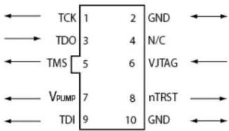
Figure 28 · FlashPro3 10-Pin Connector
Note: All ground pins must be connected. The rectangular shape shows connections on the programmer itself. Arrows show current flow towards or from the rectangular programmer.
The table below shows a description of the signals.
Table 7 · FlashPro3 Signal Description
| Signal Description | |
| VPUMP 3.3V | Programming voltage |
| GND Signal | reference |
| TCK JTAG clock | |
| TDI JTAG data input to device | |
| TDO | JTAG data output from device |
| TMS JTAG mode select | |
| nTRST | Programmable output pin may be set to off, toggle, low, or high level |
| VJTAG Reference voltage from the target board | |
| N/C | Programmer does not connect to this pin |
Some designers of high-integrity boards (military and avionic) may arrange their boards so that TRST is tied to ground via a weak pull-down resistor. The purpose of this is to hold the JTAG state-machine in a reset state by default, so that even with TCK oscillating, some sudden ion bombardment or other electrical even will not suddenly throw the JTAG state-machine into an unknown state. If your design also uses a weak pull-down resistor on TRST on your board, then enabling the "Drive TRST" flag will be required to force the JTAG state-machine out of reset to permit programming to take place. With most boards, there is no need to select this flag.
JTAG Switching Characteristics
FlashPro6 Characteristics
Table 8 · JTAG Switching Characteristics for FlashPro6
| Description | Symbol | Min | Max | Unit |
| Output Delay from TCK to TDI, TMS TTCKTDI | 2 2.2 | ns | ||
| TDO setup time before TCK rising, VJTAG=3.3V | TTDOTCK | 11.4 | 481 | ns |
| TDO setup time before TCK rising, VJTAG=1.5V | TTDOTCK | 10.5 | 487 | ns |
| TDO Hold time after TCK rising | TTCKTDO | 0 | - | |
| TCK period TTCK 49.4 | - | ns |
FlashPro5/4/3/3X Characteristics
Table 9 · JTAG Switching Characteristics for FlashPro5/4/3/3X
| Description | Symbol | Min | Max | Unit |
| Output delay from TCK to TDI, TMS | TTCKTDI | -2 | 2 | ns |
| TDO setup time before TCK rising, VJTAG=3.3 | TTDOTCK | 12 | ns | |
| TDO setup time before TCK rising, VJTAG=1.5 | TTDOTCK | 14.5 | ns | |
| TDO hold time after TCK rising | TTCKTDO | 0 | ns | |
| TCK period | TTCK | 41.7 | 10667 | ns |
Illustration of the JTAG Switching Characteristics
The figure below is an illustration of the JTAG switching characteristics.

Figure 29 · JTAG Switching Characteristics
FlashPro Express Reference
FlashPro Express Start Page
The FlashPro Express Start Page is the first page to show when the tool starts up. This page provides the interface for loading a project into the tool by either navigating to the project location, or clicking on one of the recently opened projects.
FlashPro Express Project Menu
| Command Function | |
| New Job Project from Programming Job | New job project folder with programming job name will be created at the specified location. |
| Open Job Project | Loads a job project into the tool by reading the information in user specified .pro file. |
| Close Job Project | Closes the current job project |
| Save Job Project | Saves the current job project |
| Set Log File | Sets the location of the Log file to your specified location. |
| Export Log File | Exports the Log file to your specified location. |
| Preferences | Allows you to select Flash Pro Express mode. |
| Execute Script | Runs your specified Tcl script. |
| Export Script File | Exports all commands run in this session to your specified path as a Tcl script |
| Exit Exits FlashPro Express |
FlashPro Express Edit Menu
| Command Function | |
| Clear Log Window | Clears the Log window |
FlashPro Express View Menu
The View menu shows or hides the FlashPro Express GUI elements.
| Command Function | |
| Log Window | Shows/hides the Log window |
FlashPro Express Programmer Menu
| Command Function | |
| Programmer Settings | Opens the Programmer Settings dialog box; enables you to set options for all types of supported Microsemi programmers |
| Disable Core Check During Scan and Check Chain | Disables core checking during scan and check chain operations. |
FlashPro Express Help Menu
| Command | Function |
| Help Topics Opens the help | |
| Microsemi Technical Support | Opens the Microsemi technical support site. |
| Microsemi Web Site | Opens the Microsemi website in your default browser |
| User Guide Opens the FlashPro Express User Guide. | |
| Check for Software Updates | Checks for software updates (works only if you are connected to the internet) |
| About FlashPro Express | Lists the FlashPro Express release information |
FlashPro Express Log Window and Status Bar
FlashPro Express Log Window
The FlashPro Express log window shows status messages for user activity. Click on the appropriate tab (Messages, Errors, Warning, Info) to filter messages by type.
- Use the right-click menu to copy text, clear the log, and scroll the log.
- Use the def variable LOG_WINDOW_BUFFER_SIZE to set the buffer size.
• Use the View menu to show or hide the Log window.
FlashPro Express Status Bar
The Status Bar at the bottom displays the status of the load project action.
Appendix A: Sample Programming and SmartDebug Times Using FlashPro5/FlashPro6
The tables in this appendix show sample programming times using FlashPro5 and FlashPro6 programmers.
The following table shows sample PPD programming times.
| Devices1 | PPD Programming Time2 (mm:ss) | ||
| FlashPro5 FlashPro6 | |||
| TCK=4MHz TCK=4MHz TCK=20MHzUSB 2.0 USB | 2.0/3.0 USB 2.0/3.0 | 3 | |
| M2S/A2GL 005 | |||
| M2S/A2GL 010 | |||
| M2S/A2GL 025 | |||
| M2S/A2GL 050 | 2min 9sec | 2min 10sec | 2min 2sec |
| M2S/A2GL 060 | |||
| M2S/A2GL 090 | |||
| M2S/A2GL 150 | 4min 21sec | 4min 19sec | 3min 54sec |
| RTG4 | 2min 10sec | 1min 56sec | 1min 33sec |
| MPF100 | 39sec | 28sec | 23sec |
| MPF200 | 1min 3sec | 43sec | 28sec |
| MPF300 | 1min 33sec | 1min 4sec | 43sec |
| MPF500 | 1min 57sec | 1min 34sec | 1min |
Notes:
1 FlashPro6 supports JTAG programming for all SmartFusion2, IGLOO2, RTG4 and PolarFire devices.
2 To benefit from the improved programming time using FlashPro6, use the PPD file format for SmartFusion2, IGLOO2 and PolarFire devices. Programming time speed up with PPD will be added in future releases.
3 To ensure successful programming at 20MHz TCK, appropriate steps need to be taken to ensure signal integrity of the JTAG signals.
The following table shows sample SPI Flash programming times (all using PPD flow)
SPI Flash Programming
Splash Kit
| (N25Q00AA13GSF40G / MT25QL01GBBB8ESF-0SIT TR) 1 10MByte data | PPD Programming Time | ||||
| FlashPro 54 | FlashPro 62 | ||||
| TCK = 4MHZ TCK = 15MHz 3 TCK = 4MHZ TCK = 15MHz 3 | TCK = 20MHz 3 | ||||
| USB 2.0 | USB 2.0 | USB 2.0/3.0 | USB 2.0/3.0 | USB 2.0/3.0 | |
| Program SPI Flash | 8min 30sec | 5min 29sec | 22min 12sec | 13min 9sec | 12min 11sec |
| Verify SPI Flash | 2hrs 22min 10sec | 2hrs 10min 28sec | 23min 05sec | 14min 17sec | 13min 21sec |
| Read SPI Flash | 2hrs 34min 20sec | 2hrs 23min 45sec | 22min 30sec | 13min 54sec | 12min 55sec |
| Erase SPI Flash | 19sec | 18sec | 1min 51sec | 1min 49sec | 1min 48sec |
Notes:
1 SPI Flash programming has been tested on N25Q00AA and MT25QL01G/MT25QU01G devices only. Contact technical support for other SPI-Flash device support needs.
2 FlashPro6 has longer programming times for SPI Flash devices, when compared to FlashPro5. However, readback and verification times are significantly shorter. Programming time for FlashPro6 will be improved in future releases.
3 To successfully program the device at a high TCK frequency, appropriate steps must be taken to ensure signal integrity of the JTAG signals.
4 FlashPro5 supports MT25QL01G and N25Q00AA13Gxx40G only.
Contacting Microsemi
Microsemi SoC Products Group Headquarters
Microsemi Corporation is a supplier of innovative programmable logic solutions, including field-programmable gate arrays (FPGAs) based on antifuse and flash technologies, high-performance intellectual property (IP) cores, software development tools, and design services targeted for the high-speed communications, application-specific integrated circuit (ASIC) replacement, and radiation-tolerant markets.
| Address: Microsemi SoC | Products Group3870 North First StreetSan Jose, CA 95134 |
| Phone: | 408-643-6000 |
Contact Information
For the most up-to-date contact information, check the Microsemi Home Page.
Contact information for FPGAs & SoCs can be found at the FPGAs and SoCs Support Page
If you do not have internet access, the following information was accurate at the time of publication:
• Technical Support
• Web: https://soc.microsemi.com/mycases
• Phone (NA): 800.262.1060
• Phone (Int'l): +1 650.313.4460
• Email: soc_tech@microsemi.com
- Customer (non-technical) Support
• Phone: +1 650.318.2470
• Email: customer.service@microsemi.com
• Sales Support
- For pricing, order status and lead time information for all Microsemi SoC products, contact your Microsemi Sales Representative
- Technical Support for RH and RT FPGAs that are regulated by International Traffic in Arms Regulations (ITAR)
• Phone (NA): 888.988.ITAR
• Phone (Int'l): +1 650.318.4900
- Email: soc_tech_itar@microsemi.com
Regulatory and Compliance Information
EU Declaration of Conformity:
This product complies with Directive 2011/65/EU of the European Parliament and of the Council of 8 June 2011 on the restriction of the use of certain hazardous substances in electrical and electronic equipment.
To view the Declaration of Conformity in English:
http://www.microsemi.com/index.php?option=com_docman&task=doc_download&gid=131772
Non-English:
http://www.microsemi.com/index.php?option=com_docman&task=doc_download&gid=131748
Markings:

This product complies with 2004/108/EC, Electromagnetic Compatibility (EMC) Directive
For Korea:

- MICROSEMI
- MICROCHIP COMPANY
- MICROSEMI CORPORATE
- ABOUT MICROSEMI
- TABLE OF CONTENTS
- INTRODUCTION TO FLASHPRO EXPRESS....4
- GETTING STARTED....7
- PROGRAMMER SETTINGS AND OPERATIONS....16
- CHAIN PROGRAMMING....20
- FLASHPRO EXPRESS MODES 22
- TCL COMMANDS - FLASHPRO EXPRESS ....26
- TROUBLESHOOTING 29
- SMARTDEBUG 45
- ELECTRICAL PARAMETERS 46
- ELECTRICAL SPECIFICATIONS 49
- FLASHPRO EXPRESS REFERENCE 55
- APPENDIX A: SAMPLE PROGRAMMING AND SMARTDEBUG TIMES USING FLASHPRO5/FLASHPRO6....50
- CONTACTING MICROSEMI 52
- INTRODUCTION TO FLASHPRO EXPRESS
- ABOUT FLASHPRO EXPRESS
- ABOUT FLASHPRO PROGRAMMER
- SECURE JOB PROGRAMMING
- MIGRATING FLASHPRO PROJECTS TO FLASHPRO EXPRESS
- SUPPORTED FAMILIES - FLASHPRO EXPRESS
- INSTALLING FLASHPRO EXPRESS SOFTWARE AND HARDWARE
- GETTING STARTED
- STARTING FLASHPRO EXPRESS
- FLASHPRO EXPRESS INTERFACE
- CREATING A JOB PROJECT FROM A FLASHPRO EXPRESS JOB
- LOAD A JOB PROJECT
- TO OPEN A PROJECT
- SAVING A JOB PROJECT
- PROGRAMMING TUTORIALS
- PARALLEL PROGRAMMING WITH FLASHPRO5/4/3/3X
- CHAIN PROGRAMMING TUTORIAL
- TO PROGRAM A CHAIN
- PROGRAMMER SETTINGS AND OPERATIONS
- INTRODUCTION
- PROGRAMMER SETTINGS
- FLASHPRO5/4/3/3X PROGRAMMER SETTINGS
- DEFAULT SETTINGS
- TCK SETTING (FORCE TCK FREQUENCY)
- DEFAULT TCK FREQUENCY
- PING PROGRAMMERS
- PERFORMING A SELF-TEST
- SCANNING AND CHECKING A CHAIN
- TO SCAN A CHAIN
- ENABLING AND DISABLING PROGRAMMERS
- RENAMING A PROGRAMMER
- REMOVING A PROGRAMMER
- SELECTING AND RUNNING AN ACTION
- TO SELECT A PROGRAMMING ACTION
- TO RUN THE SELECTED PROGRAMMING ACTION
- CHAIN PROGRAMMING
- CHAIN ORDER
- MULTIPLE DEVICE CHAIN PROGRAMMING
- DEVICE PROGRAMMING COMPATIBILITY
- PROGRAMMER SUPPORT
- FLASHPRO EXPRESS MODES
- DEVICE CONFIGURE OPTIONS
- 1.1 ENABLE/DISABLE DEVICE FOR PROGRAMMING
- NOTES
- 1.2 LOAD PROGRAMMING FILE
- 1.3 SELECT A PROGRAMMING ACTION AND CONFIGURE ACTIONS AND PROCEDURES PER DEVICE
- 1.4 LOAD SPI FLASH FILE
- 1.5 SELECT SPI FLASH ACTION
- PROGRAM DEVICE SELECTED ACTIONS
- TCL COMMANDS - FLASHPRO EXPRESS
- ABOUT TCL COMMANDS - FLASHPRO EXPRESS TCL COMMAND REFERENCE
- RUNNING TCL SCRIPTS FROM WITHIN FLASHPRO EXPRESS
- TO EXECUTE A TCL SCRIPT FILE WITHIN FLASHPRO EXPRESS
- RUNNING TCL SCRIPTS FROM THE COMMAND LINE
- TO EXECUTE A TCL SCRIPT FILE IN THE FLASHPRO EXPRESS SOFTWARE FROM A SHELL COMMAND LINE
- EXPORTING TCL SCRIPTS FROM WITHIN FLASHPRO EXPRESS
- TO EXPORT A SET OF TCL COMMANDS FROM THE FLASHPRO EXPRESS HISTORY
- TROUBLESHOOTING
- SMARTDEBUG
- ELECTRICAL PARAMETERS
- DC CHARACTERISTICS FOR FLASHPRO6
- DC CHARACTERISTICS FOR FLASHPRO5/4/3/3X
- ELECTRICAL SPECIFICATIONS
- FLASHPRO6
- FLASHPRO5
- FLASHPRO4
- FLASHPRO3
- JTAG SWITCHING CHARACTERISTICS
- FLASHPRO6 CHARACTERISTICS
- FLASHPRO5/4/3/3X CHARACTERISTICS
- ILLUSTRATION OF THE JTAG SWITCHING CHARACTERISTICS
- FLASHPRO EXPRESS REFERENCE
- FLASHPRO EXPRESS START PAGE
- FLASHPRO EXPRESS VIEW MENU
- FLASHPRO EXPRESS LOG WINDOW AND STATUS BAR
- FLASHPRO EXPRESS LOG WINDOW
- FLASHPRO EXPRESS STATUS BAR
- APPENDIX A: SAMPLE PROGRAMMING AND SMARTDEBUG TIMES USING FLASHPRO5/FLASHPRO6
- SPI FLASH PROGRAMMING
- CONTACTING MICROSEMI
- MICROSEMI SOC PRODUCTS GROUP HEADQUARTERS
- CONTACT INFORMATION
- REGULATORY AND COMPLIANCE INFORMATION
Brand : Microchip
Model : MPFS160TL
Category : Programmer électronique