
BKS-R6010 - Remote control SONY - Free user manual and instructions
Find the device manual for free BKS-R6010 SONY in PDF.
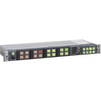


| Product Type | Video Switcher / Router |
| Brand | Sony |
| Model | BKS-R6010 |
| Form Factor | 19-inch rack mount, 1U height |
| Dimensions (W x H x D) | 482 x 44 x 300 mm |
| Weight | 4.5 kg |
| Power Supply | 100-240V AC, 50/60 Hz, 50W |
| Video Inputs | 8x BNC composite video, 4x SDI |
| Video Outputs | 4x BNC composite video, 2x SDI |
| Control Interface | RS-232, Ethernet |
| Cooling | Internal fan, front air intake |
| Operating Temperature | 0°C to 40°C |
| Storage Temperature | -20°C to 60°C |
| Mounting | 19-inch rack mountable with included ears |
| Included Accessories | Power cord, rack ears, user manual |
| Use | Professional video routing and switching |
Frequently Asked Questions - BKS-R6010 SONY
User questions about BKS-R6010 SONY
0 question about this device. Answer the ones you know or ask your own.
Ask a new question about this device
Download the instructions for your Remote control in PDF format for free! Find your manual BKS-R6010 - SONY and take your electronic device back in hand. On this page are published all the documents necessary for the use of your device. BKS-R6010 by SONY.
USER MANUAL BKS-R6010 SONY
OPERATION MANUAL English
1st Edition (Revised 2)
WARNING
To reduce the risk of fire or electric shock, do not expose this apparatus to rain or moisture.
To avoid electrical shock, do not open the cabinet. Refer servicing to qualified personnel only.
THIS APPARATUS MUST BE EARTHED.
AVERTISSEMENT
This unit has no power switch.
When installing the unit, incorporate a readily accessible disconnect device in the fixed wiring, or connect the power plug to an easily accessible socket-outlet near the unit. If a fault should occur during operation of the unit, operate the disconnect device to switch the power supply off, or disconnect the power plug.
AVERTISSEMENT
This symbol is intended to alert the user to the presence of important operating and maintenance (servicing) instructions in the literature accompanying the appliance.
For the customers in the USA
This equipment has been tested and found to comply with the limits for a Class A digital device, pursuant to Part 15 of the FCC Rules. These limits are designed to provide reasonable protection against harmful interference when the equipment is operated in a commercial environment. This equipment generates, uses, and can radiate radio frequency energy and, if not installed and used in accordance with the instruction manual, may cause harmful interference to radio communications. Operation of this equipment in a residential area is likely to cause harmful interference in which case the user will be required to correct the interference at his own expense.
You are cautioned that any changes or modifications not expressly approved in this manual could void your authority to operate this equipment.
All interface cables used to connect peripherals must be shielded in order to comply with the limits for a digital device pursuant to Subpart B of Part 15 of FCC Rules.
WARNING: THIS WARNING IS APPLICABLE FOR USA ONLY.
If used in USA, use the UL LISTED power cord specified below.
DO NOT USE ANY OTHER POWER CORD.
Plug Cap: Parallel blade with ground pin
(NEMA 5-15P Configuration)
Cord Type: SJT, three 16 or 18 AWG wires
Length: Minimum 1.5m (4 ft. 11 in.), Less than 2.5 m
(8 ft. 3 in.)
Rating: Minimum 10A, 125V
Using this unit at a voltage other than 120V may require the use of a different line cord or attachment plug, or both.
To reduce the risk of fire or electric shock, refer servicing to qualified service personnel.
WARNING: THIS WARNING IS APPLICABLE FOR OTHER COUNTRIES.
- Use the approved Power Cord (3-core mains lead) / Appliance Connector / Plug with earthing-contacts that conforms to the safety regulations of each country if applicable.
- Use the Power Cord (3-core mains lead) / Appliance Connector / Plug conforming to the proper ratings (Voltage, Ampere).
If you have questions on the use of the above Power Cord / Appliance Connector / Plug, please consult a qualified service personnel.
WARNING
For the customers in Europe
This product with the CE marking complies with both the EMC Directive and the Low Voltage Directive issued by the Commission of the European Community. Compliance with these directives implies conformity to the following European standards:
• EN60950-1: Product Safety • EN55103-1: Electromagnetic Interference (Emission) • EN55103-2: Electromagnetic Susceptibility (Immunity) This product is intended for use in the following Electromagnetic Environment: E4 (controlled EMC environment, ex. TV studio)
For the customers in Europe
The manufacturer of this product is Sony Corporation, 1-7-1 Konan, Minato-ku, Tokyo, Japan.
The Authorized Representative for EMC and product safety is Sony Deutschland GmbH, Hedelfinger Strasse 61, 70327 Stuttgart, Germany. For any service or guarantee matters please refer to the addresses given in separate service or guarantee documents.
This apparatus shall not be used in the residential area.
For the customers in Europe, Australia and New Zealand
WARNING
This is a Class A product. In a domestic environment, this product may cause radio interference in which case the user may be required to take adequate measures.
For the State of California, USA only
Perchlorate Material – special handling may apply, See www.dtsc.ca.gov/hazardouswaste/perchlorate Perchlorate Material : Lithium battery contains perchlorate.
For the customers in Taiwan only

Please recycle waste batteries.
Table of Contents
Manual Line-up 6
Overview......6
Features 6
Setting the Select Button Functions ....8
Selection System 8
Control System 8
Functions of an S-BUS System ....8
Use of Multiple Control Units (V2.0 and above)....9
Route Function 9
Destination Group Control ....10
System Connection Example....11
Notes on Operations 12
Locations and Functions of Parts......13
Front Panel 13
Rear Panel....15
Status Display Window 16
Switching the Crosspoint ....21
Selecting the Selection System....21
BPS (Direct)-Selection System ......21
MD (Multi-Destination)-Selection System....23
TPN (Type + Number)-Selection System ...24
Keypad-Selection System......26
Assigning Functions to the Select Buttons ....27
Various Functions ....30
Breakaway Function....30
Phantom Function....31
Pages and Page Groups ....32
Monitoring Two Sources (Chop) ......33
Protecting a Destination from Being Switched....34
Preventing Accidental Operations (Lock)....35
Monitor Function....36
Monitoring the Input and Output Signals (V2.0 and above)....37
Resetting....37
Error Display....38
Specifications 39
Manual Line-up
The following manuals have been prepared to thoroughly explain this Universal LCD Remote Panel. Under the directions provided in this manual and in correlation with your needs, refer to the manual that suits your purposes best.
Operation Manual (this manual)
This manual supplies information related to a simple outline of this unit, connection examples, an explanation of each part, operations, and the specifications.
Installation Manual
This manual supplies information related to the hardware settings required for initial setup and the maintenance and initial service for this unit, such as board replacement. This manual is found on the CD-ROM supplied with a device such as an integrated routing system.
System Setup Manual
This manual supplies information related to the initial settings, settings on the control terminal, and verification of operation.
This manual is found on the CD-ROM supplied with a device such as an integrated routing system.
Maintenance Manual (option)
This manual supplies information related to the servicing of each parts level (i.e., the essential points for adjustment, mounting diagrams, circuit diagrams, and a detailed parts list).
To obtain this manual, please contact your Sony representative.
Protocol Manual (option)
Supplies information related to the protocols used to control the routing switcher system. The following manual is available for your reference regarding the protocols supported by the routing switcher system:
- SONY ROUTING SWITCHER SYSTEM REMOTE 1 (S-BUS/ROT16) PROTOCOL and COMMAND SPECIFICATIONS Part number: 9-977-476-xx
- SONY ROUTING SWITCHER SYSTEM REMOTE 2 (Cart++) PROTOCOL and COMMAND SPECIFICATIONS Part number: 9-967-261-2x
To obtain this manual, please contact your Sony representative.
Overview
The BKS-R6010 Universal LCD Remote Panel switches the input signal (called a source) fed to one of the routing switchers that is adapted to the 100BASE-TX ETHERNET or S-BUS remote and connected to the 100BASE-TX ETHERNET or S-BUS data link and supplies the selected signal to the designated output (called a destination). Source and destination switching are performed with the select buttons whose functions you define with the control terminal connected to the primary station.
Features
Status display window using a color TFT LCD
A large LCD display shows the current setting status of sources, destinations, description names, levels, etc.
Multifunction select buttons using a color TFT LCD
The large select buttons on the front panel are designed for easy operation. They light in green or amber, dimly or brightly, to indicate their functions and the currently selected source and destination.
The color and saturation of the buttons can be set according to the environmental conditions at the control terminal, making it easy to identify each button's function (V2.0 and above).
Note
This manual describes the button color with the factory setting. If you change the color settings at the control terminal, the actual color will differ from the description in this manual.
Select function using a selector knob
A selector knob is used for selecting sources or destinations, or for switching crosspoints by rotating or pushing.
Switchable for up to 1024 sources and 1024 destinations
A BKS-R6010 can switch crosspoints of up to 1024 sources and 1024 destinations.
Buttons to select sources and destinations
All select buttons on the front panel can be used as source select buttons or destination select buttons. Your settings on the control terminal define their functions. The defined function for a button is indicated by the color; green for source and amber for destination.
Route function to show expanded sources
If a switcher does not have a cascade function, and you need to expand the number of sources, the route function makes it possible to detect a crosspoint in the expanded switcher and to have the selected source name displayed in the display window.
Controllable up to 16 levels 1)
Up to 16-level control is possible by assigning it on the control terminal.
1) To handle different kinds of signals simultaneously, it is necessary to use a routing switcher for each type of signal, and these types are called "levels." For example, a recording to be made on a VTR requires the use of five signal levels: video, audio 1, audio 2, time code and remote-control signals.
Different sources for levels selectable (breakaway function)
You can select and display different sources for levels. This is called the breakaway function.
Monitor function to watch the selection for the other destination
When a destination you wish to monitor is set as a monitor destination, the same source as the signal for the monitor destination is automatically obtained when the monitor function is set to ON.
Chop function to switch two sources alternately
Two sources are switched alternately at a specified interval automatically.
Several crosspoints switchable with the touch of a button (phantom function or salvo function)
When multiple crosspoints have been set as a phantom on the control terminal, all the crosspoints defined for a phantom can be switched by pressing one button.
Connectable with a single cable
The unit can be connected to Sony routing switchers using a single 75Ω coaxial cable and can control the switchers via the S-BUS data link.
Control with Ethernet
When the NETWORK connector on the BKS-R6010 is connected to the primary station corresponding to Ethernet control via the Ethernet switch, an Ethernet network is buildup. This enables comprehensive control from a distance.
Dual control system
When the BKS-R6010 and the primary station are connected with the S-BUS data link using the REMOTE 1 connector and with Ethernet using the NETWORK connector, a dual network system is constructed. This assures stable operation even if either system is disconnected.
Multiple naming using aliases
When BZR-2000 Routing Switcher System Setup Software is used, a single connector can have up to 8 names, using aliases of up to 7 adding to a description name.
Self-diagnostic function
When the power is turned on, the unit automatically checks communication on the S-BUS data link, as well as the buttons on the front panel, which light in succession. The results appear in the status display window.
Operation on various voltages
The unit can operate on voltages from 100 V to 240 V AC without voltage adaptation.
Source or destination name changeable with the selector knob
A source or destination name assigned to the select buttons on the control terminal can be changed using the selector knob on the front panel.
Expanding the number of controllable sources and destinations (complying with V2.0 and above)
You can use multiple units of the remote control panel 1) in combinations as to work as one unit to expand the number of sources and destinations to be controlled. One switching system can have up to 10 sets of combinations like this, and up to 253 control units can be used in one set. The maximum number of control units that can be used in one switching system is also 253.
1) Remote control panel usable for expanding the number of sources and destinations: BKS-R1617/R1617A/R1618/R1621/R3216/R3219/R3219A/R3220/R6010
Web setting function (complying with V2.0 and above)
If the IXS-6600/6700 (V2.2 and above) is used as the primary station, or if a computer used as a control terminal has the BZR-26 installed, settings for the BKS-R6010 can be performed on a Web browser.
For details on settings, refer to the Installation Manual.
Two-byte characters usable (complying with V2.0 and above)
Chinese characters can be used in the description name and alias name.
Usable as a subnet controller (complying with V2.1 and above)
The BKS-R6010 connected to the primary station can be used as a subnet controller that enables control of devices of a third station according to your setting made at the control terminal.
Virtual monitor function (V2.0 and above)
When the monitor select function is set on the BKS-R6010 at the control terminal, any input and output signals can be output from the connector set as the monitor output connector at the control terminal, for monitoring these signals.
Setting the Select Button Functions
The select buttons can be used as either source select buttons or destination select buttons. The control terminal or the assigning function of this unit allows you to define the function of each button. The settings are made for each button.
For details on the assigning function, see “Assigning Functions to the Select Buttons” on page 27.
For details on settings on the control terminal, refer to the System Setup Manual.
Selection System
The BKS-R6010 can switch crosspoints with one of the following four systems:
BPS (direct)-selection system
With the touch of a source/destination select button, the source or destination assigned to the button is selected. When this system is used, source or destination names should be assigned to the 16 select buttons on the control terminal in advance.
For details on the BPS-selection system, see “BPS (Direct)-Selection System” on page 21.
MD (Multi-Destination)-selection system
If a source and destination have been assigned as a pair to a select button, you can switch the crosspoint by pressing that button.
For details on the MD-selection system, see “MD (Multi-Destination)-Selection System” on page 23.
TPN (Type + number)-selection system
To select a source or destination, you designate a type name of up to four alphanumeric characters, such as VTR, FLM, etc., and a number from 001 through 999. On the source/destination select buttons, the type names should be assigned on the control terminal in advance. With this system, the BKS-R6010 functions as a 1024-source/1024-destination selector.
The destinations or sources which can be controlled with the BKS-R6010 can be limited on the control terminal when required.
For details on the TPN-selection system, see “TPN (Type + Number)-Selection System” on page 24.
Keypad-selection system
To select a source or destination, designate the description name, using the select buttons.
Four or five alphanumeric characters are assigned to each select button.
In the Keypad-selection system, all description names corresponding to the characters of the pressed select buttons are searched for. With this system, the BKS-R6010 functions as a 1024-source/1024-destination selector. The destinations or sources which can be controlled with the BKS-R6010 can be limited on the control terminal when required.
For details on the Keypad-selection system, see "Keypad-Selection System" on page 26.
Control System
The BKS-R6010 has two types of remote connectors; REMOTE 1 (standard S-BUS), REMOTE 2 (RS-422A), and NETWORK (Ethernet).
For details on remote connectors, refer to the Installation Manual.
Functions of an S-BUS System
An S-BUS control system transmits the control signals among several routing switchers and remote control panels (routing switcher control units) that are connected with one coaxial cable. In an S-BUS control system, one switcher is designated as the primary station that controls the entire system, and the remaining switchers and remote control panels are designated as secondary stations. Signal transmission among the secondary stations is controlled by the primary station.
The S-BUS control system has the following features;
• LAN (Local Area Network) type control system using a single 75Ω coaxial cable. - Possible extension of the coaxial cable up to 500 meters when a BELDEN 8281 or equivalent cable is used. - Possible connection and disconnection of a switcher or remote control panel to the S-BUS line during normal operations without turning the power off. - Control of multiple S-BUS lines and up to 254 switchers and remote control panels (including the primary station) from the routing switcher designated as the primary station. - Possible connection of a maximum of 128 routing switchers and remote control panels on one S-BUS line.
- Display of errors detected through the self-diagnostic function on a PC (terminal emulator) connected to the primary station on the S-BUS line.
- Storage and future recovery of the settings (system settings and table data) made with the PC (terminal emulator) and the crosspoint data in/from a computer using the BZR-20 Routing Switcher Data Backup Software supplied with the HXS-X5800, BKSP-R80, ISX-6600/6700, etc.
For details, refer to the Installation Manual.
Use of Multiple Control Units (V2.0 and above)
When you control the routing switcher using the control unit, the number of controllable sources and destinations can be expanded by using multiple BKS-R1617/R1617A/R1618/R1621/R3216/R3219/R3219A/R3220/R6010 units in combination. One switching system can have up to 10 sets of multiple control units, and in one set, up to 253 control units can be used. The total number of control units used in 10 sets within one switching system is also 253. When using multiple control units in combination, one is to be set as the mother unit and the others as daughters on the control terminal. In one combination, only one unit can be used as the mother unit.
For details on setting a unit as the mother unit or a daughter unit, refer to the System Setup Manual.
![graph TD A["Routing switcher"] --> B["Mother unit"] A --> C["Daughter units"] B --> D["Remote control panel"] B --> E["Remote control panel"] B --> F["..."] C --> G["Remote control panel"] C --> H["Remote control panel"] C --> I["..."] D --> J["Remote control panel"] D --> K["Remote control panel"]…](/content/2026/07/1409310/images/130ebd1d18eb4f4944d85fa4092f8425c426a67e59a223da5e274a9475585cb4.jpg)
Route Function
When you use a switcher B having no cascade function and expand the number of sources by connecting another switcher A, the source name of switcher B is displayed as a selected source, and not the source name selected on switcher A. For example, when a crosspoint is switched on switcher A in the figure on the next page, normally IN5 of switcher B appears as the source name. To display the actually selected source name, you must set the route function with the control terminal. Then when you select the crosspoint set on the route function, the source on switcher A is searched for, and the name is displayed. To activate the route function, set the destination of switcher A, destination and expanded input of switcher B, and level. In the case of the figure, set “OUT1:OUT2 <IN5 10000000.”
When you use the route function, switching is possible with simple settings. For example, if you select a source (IN1) for a destination (OUT1) on switcher A, the crosspoint on switcher B (IN5-OUT2) is automatically switched.
However, when you select a source (IN1) for a destination (OUT2) on switcher B, you have to set a phantom including IN1-OUT1 and IN5-OUT2 previously. Then IN1-OUT2 is displayed if the route has been set.
Destination offset route
The destination offset route sets the destination to a substitute parameter such as (DST + *) where (*) is an offset value of the connector number of the destination. (DST) is automatically substituted with the destination selected with this unit. This function makes it possible to use expanded input for multiple destinations.
For details, refer to the System Setup Manual.
![graph TD A["Level 1 Level 1"] --> B["Switcher A Switcher B"] C["Level 2 Switcher B"] --> D["Expanded input"] style A fill:#f9f,stroke:#333 style B fill:#ccf,stroke:#333 style D fill:#cfc,stroke:#333 note1["IN 1 2 3 4"] --> A note2["OUT 1"] --> A note3["IN 5 6 7 8"] --> D note4["OUT 2 ... OUT 5"] -->…](/content/2026/07/1409310/images/7e4b7d9b2c91573220f83fd7107407ec2d1e752bfb455f5458cff7187e840f2e.jpg)
Destination Group Control
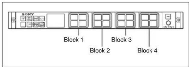
Using the MD-selection system, you can divide select buttons to several blocks and assign a single destination to each block.
System Connection Example![graph TD A["Source VTR"] --> B["Primary Station"] B --> C["Integrated Routing System IXS-6700 (P)"] C --> D["Video"] C --> E["Video"] C --> F["Audio Channel 1/2"] C --> G["Audio Channel 3/4"] C --> H["Time Code"] C --> I["Time Code"] C --> J["Audio Channel 1/2"] C --> K["Audio Channel 3/4"] C --> L[…](/content/2026/07/1409310/images/74caf76653f05cf57eeb314a6cce63e78762c2d623d4941224fefc89a7192077.jpg)
Notes on Operations
About the LCD panels
LCD panels are manufactured with extremely high-precision technology that yields effective pixel rates of 99.99% or higher. However, very rarely, one or more pixels may be permanently dark or permanently lit in white, red, blue, or green.
This phenomenon is not a malfunction. The unit may be used with confidence even if they are present.
About unstable display on LCD panels
While this unit is starting up, a vertical blue line may momentarily appear on the LCD display. This is because the display is distorted during initialization of the unit or self-diagnosis. Once the unit is activated, the line will disappear and not appear again.
Locations and Functions of Parts
Front Panel

① STATS DISP (Status Display) button
Normally the button lights in dim green. When some trouble occurs with the unit, the button flashes in red. When it is pressed, the display mode of the status display window is switched.
When you press this button after pressing the SHIFT button, description name display mode is switched on or off.
For details on switching the display, see "Display transition" on page 20.
② SRC DEST/LEVEL (Source/Destination/Level) button
Toggles the function of the select buttons between source selection and destination selection.
When you press this button after pressing the SHIFT button, the select buttons function as level select buttons.
For details, see "Display transition" on page 20.
③PG UP/GP UP (Page Up/Page Group Up) button
When button assignment data are displayed in the status display window, the displayed page is switched to the next one with this button.
When you press this button after pressing the SHIFT button, the page group is switched to the next one.
For details, see "Pages and Page Groups" on page 32.
④ASSGN (Assign) button
This button has the following two functions:
Changing the assignment of select buttons
While holding down this button, if you press a select button, the source or destination name displayed in the Preset block of the status display window will be assigned to the pressed button.
For details on button assigning, see "Assigning Functions to the Select Buttons" on page 27.
Selecting the type
While holding down this button, if you turn the selector knob, the type names will appear in the Preset block of the status display window in sequence. When the desired name appears, release the button and turn only the selector knob. The sources or destinations belonging to the selected type name will appear in the Preset block of the status display window in sequence. If you group signals by type name, you can select a signal easily.
⑤ Status display window
The display shows the status of a source, destination, level, and operation mode.
For details on the display, see "Status Display Window" on page 16.
⑥ Select buttons
These buttons can be used as source select buttons, destination select buttons, or level select buttons. The control terminal or assigning function defines the function of these buttons.
For details on the button assigning function, see "Assigning Functions to the Select Buttons" on page 27.
Source selection function (lit in green)
When the SRC DEST/LEVEL button is lit in green, the buttons function as source select buttons. When you press a button, the signal fed to the switcher (source) corresponding to the pressed button is selected and is supplied to the output connector (destination). (If the phantom function has been set, the sources set for the button are selected.)
If immediate lamp-light mode has been set, the pressed button lights in bright green to show the selected source. If status display mode has been set, the system checks that the selected crosspoint has been switched, and the button lights in bright green.
Notes
- When the PROT lamp is lit, source switching is disabled.
- When the source select button is lit in dark blue, the source has been selected on another level in the breakaway function.
For details on the breakaway function, see “Breakaway Function” on page 30.
Destination selection function (lit in amber)
When the SRC DEST/LEVEL button is lit in amber, the buttons function as destination select buttons. When you press a button, the output connector of the switcher (destination) corresponding to the pressed button is selected. The pressed button lights in bright amber to show the selected destination.
Level selection function
Press the SHIFT button, then the SRC DEST/LEVEL button. The select buttons function as level select buttons. Pressing this button selects the level.
⑦SHIFT button
When multiple functions are assigned to a button, pressing this button switches the function.
⑧Selector knob
When the SRC DEST/LEVEL button is lit in green, turning this knob selects a source. When the SRC DEST/LEVEL button is lit in amber, turning this knob selects a destination.
While holding down the ASSGN button, if you turn the selector knob, the type names will appear in the Preset block of the status display window in sequence. When the desired name appears, release the button and turn only the selector knob. The sources or destinations belonging to the selected type name will appear in the Preset block of the status display window in sequence.
When you turn the knob, the type names or numbers appear one by one. If you turn the knob quickly, the
displayed type name or number is jumped by every 50 or 100 depending on the speed.
You may limit the available names on the control terminal, as described below.
- A source name to which secret has been set is skipped.
- Sources and destinations can be limited using the available source/destination table.
To avoid any problem caused by the knob being accidentally pressed, the function that is activated when this knob is pressed can be disabled at the control terminal (V2.0 and above).
⑨ CLEAR CHOP/LOCK button
Press this button to clear the entered data.
If you press this button after pressing the SHIFT button, the lock function is activated.
If you hold this button pressed for more than three seconds, the chop function is activated.
Lock function
If you press this button after pressing the SHIFT button, the buttons on the front panel other than this button will be disabled. The lock icon appears in the status display window. This prevents undesired switching caused by accidental touching of select buttons.
For details on the Lock function, see “Preventing Accidental Operations (Lock)” on page 35.
Chop function
When you hold this button pressed for more than 3 seconds, it lights in green, and chop mode is activated. In chop mode, a source selected before the chop mode was activated and a source selected in chop mode are switched alternately at a specified interval.
For details on the Chop function, see “Monitoring Two Sources (Chop)” on page 33.
⑩ PG DN/GP DN (Page Down/Page Group Down) select button
When button assignment data are displayed in the status display window, the displayed page is switched to the previous one with this button.
When you press this button after pressing the SHIFT button, the page group is switched to the previous one.
For details, see "Pages and Page Groups" on page 32.
⑪ ENTRY button
Selects the selection system for switching crosspoints. When you press the PROT button together with the ENTRY button, the software is reset.
⑫ PROT (Protect) button
When you press this button, it lights in green, and the currently selected destination (output) is protected. The Self (self-protect icon) is displayed in the status display
window. When a destination is protected, switching of sources for the destination is disabled.
To release protection, press the PROT button so that the lamp goes dark.
When you press the PROT button together with the ENTRY button, the software is reset.
Notes
- If the protection has been set for in ON AIR mode at the control terminal, switching is enabled independently of the protection setting. Normally set the protection for NORMAL mode.
- If (protection on the other station) is displayed, you cannot release protection from this unit.
Rear Panel
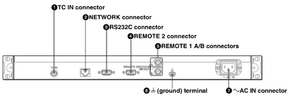
① TC IN (timecode input) connector (BNC-type) For timecode input. (complying with V2.0 and above) ② NETWORK connector (modular jack) For 100 BASE-TX network connections.
CAUTION
For safety, do not connect the connector for peripheral device wiring that might have excessive voltage to this port. Follow the instructions for this port.
CAUTION
When you connect the NETWORK cable of the unit to a peripheral device, use a shielded-type cable to prevent malfunction due to radiation noise.
③ RS232C connector (D-sub 9-pin)
For servicing.
Connect to a PC for downloading software or monitoring communication status.
④ REMOTE 2 connector (D-sub 9-pin)
To connect an RS-422A communication line. (complying with V2.1 and above)
⑤ REMOTE 1 A/B connectors (BNC-type)
Connect to the S-BUS line using the Y bridge (supplied) and 75Ω coaxial cable (BELDEN 8281 or equivalent). The REMOTE 1 B connector functions only when the unit is used as a subnet controller. (complying with V2.1 and above)
⑥ Ground (ground) terminal
For signal grounding.
⑦ AC IN (AC input) connector
Connect to an AC power source using the designated AC power cord.
Status Display Window
Display in the status display window varies depending on the display mode. The display mode is automatically decided when the selection system is selected. It is changed by pressing the STATS DISP button.
Icon
The icons shown below appear depending on the operation status.
| When the red tally lamp on the switcher is lit | |
| When the green tally lamp on the switcher is lit | |
| Other§ | When protected on the other station |
| Self § | When protected on this unit |
| CHOP | Chop mode |
| Lock mode | |
| BPS | BPS-selection system |
| MD | MD-selection system |
| TPN | TPN-selection system |
| KPD | Keypad-selection system |
| S a) | S-BUS connection (lights in red when the unit functions as a subnet controller and detects the disconnection from the REMOTE 1 B connectorp) |
| E a) | Ethernet connection |
| → a) | Connection with the primary station or a subnet controller |
| → b) | Subnet connection |
a) Complying with V2.0 and above
b) Complying with V2.1 and above
BPS display mode
This mode is for the immediate switching mode of the BPS- or MD-selection system.
Example for the BPS-selection system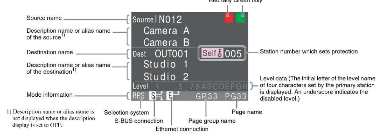
Preset display mode
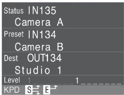
This mode is for the Keypad-selection system or TPN-selection system, or the preset selection mode of the BPS-selection system or MD-selection system.
Example for the Keypad-selection system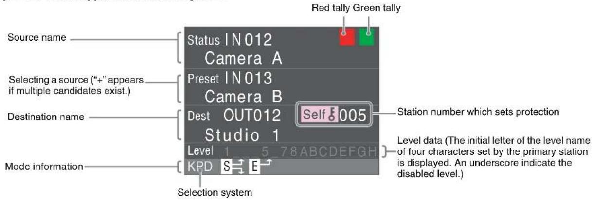
Level display mode
Displaying Type + Number name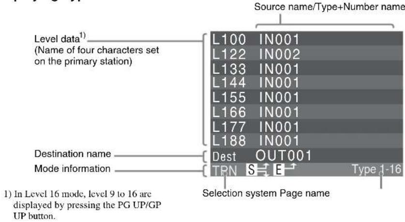
Displaying description name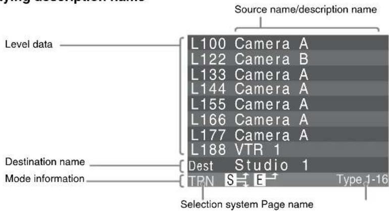
Connector data
Source data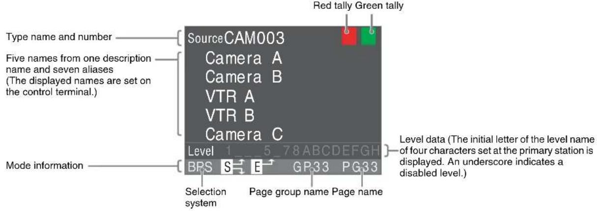
Destination data
Changing the display block (V2.0 and above)
The displayed position of the Source block and Dest block can be changed by settings at the control terminal.
BPS display mode, Preset display mode, Level display mode

Display transition
BPS display mode![graph TD A["Description display: OFF"] --> B["Connector data"] B --> C["Source data"] C --> D["Destination data"] D --> E["Description display: ON"] subgraph_Display_1["Description display: ON"] A -->|SHIFT| B B -->|STATUS DISP| A C -->|SHIFT| E D -->|SHIFT| E end subgraph_Display_2["Description dis…](/content/2026/07/1409310/images/9a83308f0a1294b51998d8c22e83de6b18ac79e555ebfa502692d1e3f0449986.jpg)
Preset display mode![graph TD A["Description display: OFF"] --> B["Connector data"] B --> C["Level display"] C --> D["Description display: ON"] subgraph Description display: OFF E["Status IN001"] F["Preset IN012"] G["Dest OUT001"] H["Level 1"] I["BPS S H GP33 PG33"] J["SHIFT"] --> K["STATUS DISP"] L["STATS DSP"] M["Stat…](/content/2026/07/1409310/images/323b94db74aefcb916ea7ea22a6f8e9a0deb26932f01ed5bd73023baa99f849e.jpg)
Switching the Crosspoint
The source name or destination name for each select button on the front panel is defined at the control terminal. Using these buttons, you can select a source and destination for switching a crosspoint. You can also select a source or destination and switch the crosspoint, using the selector knob. The system has the two switching methods (immediate switching, which switches the crosspoint immediately after you select a source, and preset switching, which switches the crosspoint when you press the TAKE button). You can select one or the other at the control terminal.
The BKS-R6010 has four selection systems: the BPS-selection system, MD-selection system, TPN-selection system, and Keypad-selection system. The selection system is selected with the ENTRY button.
Selecting the Selection System
Four selection systems for switching a crosspoint are available. You can select the selection system by pressing the ENTRY button. Each time you press the ENTRY button, the selection system is switched as shown below. The selection system disabled at the control terminal is skipped.

![graph TD A["BPS (direct)-selection system"] --> B["MD (Multi-Destination)-selection system"] B --> C["TPN (Type + Number)-selection system"] C --> D["Keypad-selection system"]](/content/2026/07/1409310/images/fee9671583b1e9f04cb868c5dd2b4b9278a7e3dda6cb537343e8a3e698861c1b.jpg)
Note
The MD-selection system is skipped as default. To select the MD-selection system, set it enabled at the control terminal.
BPS (Direct)-Selection System
In BPS-selection system, you press a destination and source select buttons on which the corresponding functions have been assigned for switching the crosspoint.

Switching directly (immediate switching method)
The status display window is in BPS display mode.
1 Press the SRC DEST/LEVEL button to make it light in amber.
The unit is in destination selection mode, and the select buttons are lit in dim amber.
2 Press a select button to select a destination.
The unit is in source selection mode, and the select buttons are lit in dim green.
3 Press a select button to select a source.
The crosspoint is switched.

Switching using the TAKE button (preset switching method)
When the BKS-R6010 is set in preset mode at the control terminal, the status display window is in preset display mode. When you press a source select button, the function of the pressed button changes to that of the TAKE button (V2.0 and above).
It is possible to assign the TAKE function to one of the select buttons at the control terminal.
1 Press the SRC DEST/LEVEL button to make it light in amber.
The unit is in destination selection mode, and the select buttons are lit in dim amber.
2 Press a select button to select a destination.
The unit is in source selection mode, and the select buttons are lit in dim green.
The selected destination name is displayed in the Dest block of the status display window.
3 Press a select button to select a source.
The pressed button changed to the TAKE button if it has been set to do so at the control terminal.
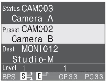
4 Press the TAKE button.
The crosspoint is switched.
Switching with the selector knob
1 Press the SRC DEST/LEVEL button to make it light in amber.
The unit is in destination selection mode, and the select buttons are lit in dim amber.
2 Turn the selector knob to select a destination.
The Preset block of the status display window is highlighted, and the destination to be selected is displayed in the Preset block of the status display window.
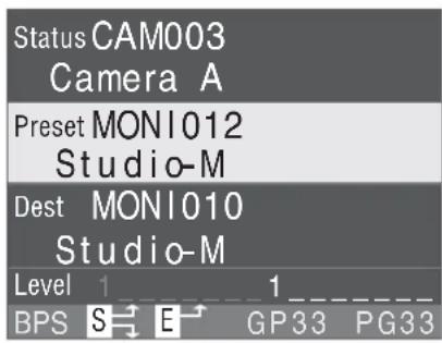
3 Press the selector knob to register a destination.
The destination is selected. The unit is in source selection mode, and the select buttons are lit in dim green.
4 Turn the selector knob to select a source.
The Preset block of the status display window is highlighted, and the source to be selected is displayed in the Preset block of the status display window.
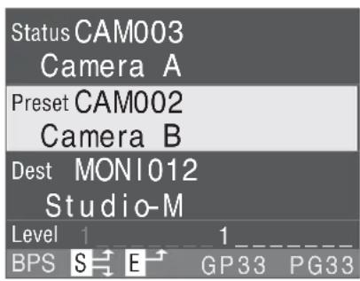
5 Press the selector knob.
The crosspoint is switched.
MD (Multi-Destination)-Selection System
In the MD-selection system, a source and destination are assigned to one select button. You can switch a crosspoint by pressing the select button.
In the MD-selection system, select buttons normally function as source select buttons. When you press the SRC DEST/LEVEL button, and the buttons light in amber, destinations are displayed on the select buttons. The status display window is in BPS display mode.
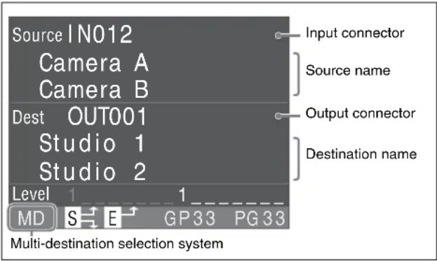
Switching directly (immediate switching method)
Press a select button. The crosspoint set on the pressed button is switched.
Switching using the TAKE button (preset switching method)
When the BKS-R6010 is set in preset mode at the control terminal, the status display window is in preset display mode. When you press a source select button, the function of the pressed button changes to that of the TAKE button. (V2.0 and above)
It is possible to assign the TAKE function to one of the select buttons at the control terminal.
1 Press a select button.
The pressed button changes to the TAKE button if it has been set to do so at the control terminal.
2 Press the TAKE button.
The crosspoint set on the select button pressed in step 1 is switched.
Switching with the selector knob
1 Turn the selector knob to display the source name to be switched in the Source block of the status display window.
2 Press the selector knob.
The crosspoint of the source and destination displayed in the status display window is switched.
Grouping the destinations
You can make groups of destinations by defining a destination on multiple select buttons and different sources on each of these buttons at the control terminal. This enables switching sources for a destination by simply pressing a source select button.
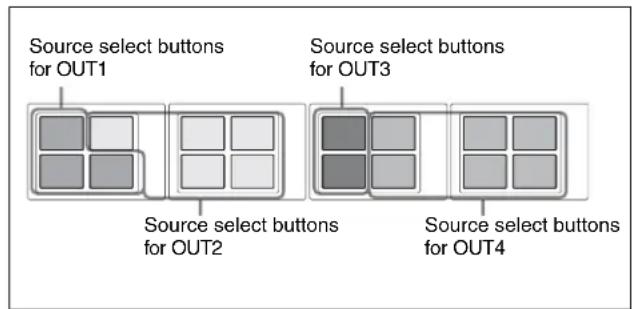
TPN (Type + Number)-Selection System
The TPN-selection system designates a source and destination by a type name and a number. The type name is specified in up to four alphanumerics, and the number in 3 digits.
You can select a source and destination with the select buttons or the selector knob.
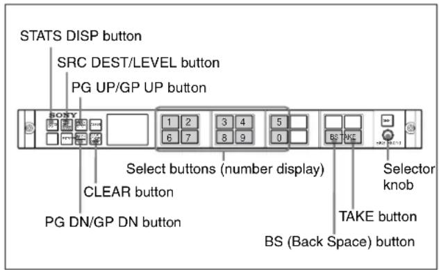
Switching with the select buttons
1 Press the SRC DEST/LEVEL button to set the destination selection mode.
The SRC DEST/LEVEL button lights in amber, and the type names for destinations appears on the select buttons.

2 Press the select button corresponding to the type name for the destination to be selected.
The type name set on the pressed button is displayed in the Preset block of the status display window. Display of the select buttons changes to number display.
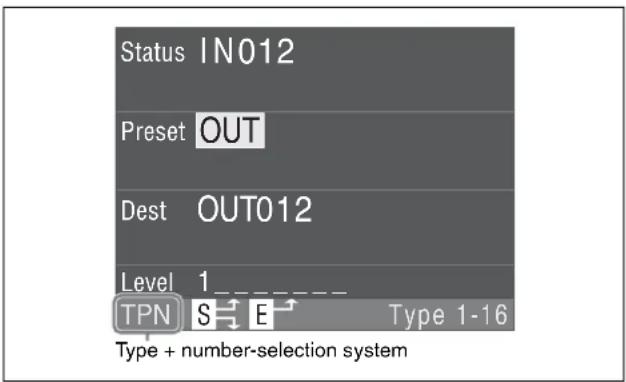
3 Press the select buttons to set a three-digit figure.

4 Press the TAKE button.
The destination is displayed in the Dest block of the status display window. The type names for sources are shown on the select buttons.
You can select the destination by pressing the selector knob.
5 Press the select button for the type name for the source to be selected.
The type name set on the pressed button is displayed in the Preset block of the status display window. Display of the select buttons changes to the number display.
6 Press the select buttons to set a three-digit figure.
The source is decided.
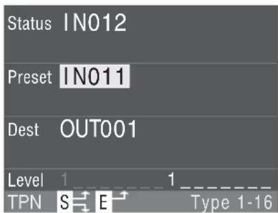
7 Press the TAKE button or push the selector knob.
The set crosspoint is switched.
To modify the entered number
Press the BS button. One character entered last is deleted.
When the selection is incorrect
If the selected source or destination has not been set at the control terminal or set disabled, "Not Found" appears in the status display window, and the STATS DISP button flashes in red.
Displaying type names
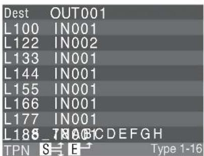
This unit can handle up to 32 type names, which are classified into three pages. On page 1, Type 1 to 16 are assigned, on page 2 Type 17 to 32 are assigned, and on page 3 various functions are assigned. To change the page, press the PG UP/GP UP button or PG DN/GP DN button. The selected page appears at bottom right in the status display window.
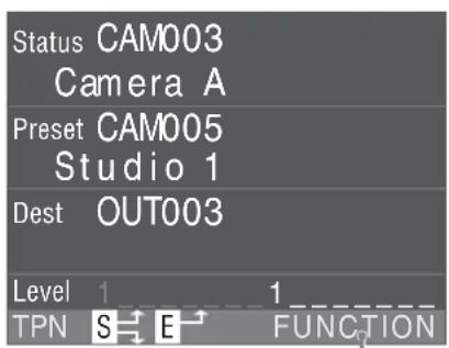
Function display
Function display (page 3)
Switching using the selector knob
1 Press the SRC DEST/LEVEL button to set the destination selection mode. 2 Turn the selector knob while holding the ASSGN button pressed until the type name of a destination to be selected appears. 3 Release the ASSGN button, then turn the selector knob to select a three-digit number. 4 Press the selector knob.
The selected destination is displayed in the Dest block of the status display window. The unit is in the source selection mode.
5 Turn the selector knob while holding the ASSGN button pressed until the type name of a source to be selected appears. 6 Release the ASSGN button then turn the selector knob to select a three-digit number. 7 Press the selector knob.
The source is set, and the crosspoint is switched.
Keypad-Selection System
The Keypad-selection system defines a description name of a source or destination using the alphanumerics assigned to the select buttons.
Two patterns of character assignment for the select buttons are available, and either of them is selected at the control terminal. The select buttons shown below are for Pattern 1.

Entering the description name
In the Keypad-selection system, you can search for description names corresponding to the entered characters. Each time you enter a character, the number of candidates is reduced. The current number of candidates is shown at bottom right in the status display window.
The target for searching can be designated to description names or alias names 1 to 7 at the control terminal. Even if Chinese characters are used as the description name and alias name, you can search for such names by entering transliterating alphabetic characters (sounding out the name) at the control terminal. (V2.0 and above)
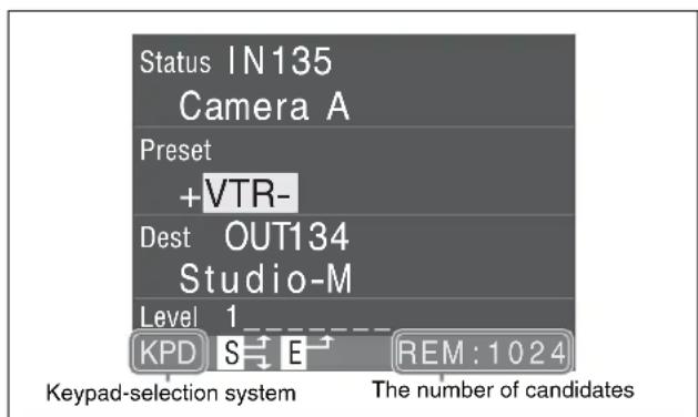
For example, to enter ABCB_ORANGE, proceed as follows:
1 Press the select buttons in order of the figure below.
![graph LR A["A #1"] --> B["BC@2"] B --> C["BC@2"] C --> D["BC@2"] D --> E["A #1"] E --> F["MNO6"] F --> G["PRS7"] G --> H["A #1"] H --> I["MNO6"] I --> J["GHI4"] J --> K["DEF3"]](/content/2026/07/1409310/images/3001e3f6499035e624f689e620ab344955ce32282f5462ac8d01c9a8d0ebb44c.jpg)
In the Preset block of the status display window, the description name corresponding to the entered character appears. If two or more names exist, "+" appears before the name, and the number of the candidates is displayed at bottom right in the status display window. Each time you press the select button, the number of the candidates is reduced.
2 When the number of candidates is reduced, press the select button or turn the selector knob to show the description name to be selected in the Preset block of the status display window.
3 Press the TAKE button or selector knob.
The selected description name is decided. When the description name for the source is decided, the crosspoint is switched.
To modify the entered data
Press the BS button. The character entered last is deleted. Each time you press the BS button, one character is deleted. When you delete all the characters to be modified, enter the correct character.
To clear the entered data
Press the CLEAR button. The entered characters are all deleted, and the source selection mode is retrieved.
If entered data are not correct
If there is no candidates for the entered characters, “Not Found” appears in the status display window. Press the BS button to delete the entered characters. If you enter a character with “Not Found” displayed, searching for the entered characters is canceled, and searching for the newly entered character begins.
If nothing is done for ten or more seconds after “Not Found” is displayed, entered characters are canceled. (V2.0 and above)
Switching a crosspoint
1 Press the SRC DEST/LEVEL button to select the destination selection mode.
The SRC DEST/LEVEL button and select buttons light in amber.
2 Enter the description name of the destination.
The selected description name appears in the Preset block of the status display window.
3 Press the TAKE button or selector knob.
The selected destination is decided, and the name appears in the Dest block of the status display window.
The unit enters source selection mode, and the select buttons light in green.
4 Enter the description name for the source. 5 Press the TAKE button or selector knob.
The crosspoint of the selected destination and source is switched.
Assigning Functions to the Select Buttons
Sources and destinations have been assigned on the select buttons at the control terminal. In the BPS-selection system or MD-selection system, these settings on the select buttons can be changed on this unit.
Notes
- You cannot assign the destination disabled at the control terminal.
- You cannot assign another function to a button on which the TAKE or level function has been set at the control terminal.
The numbers are assigned on the select buttons at the control terminal as shown below.
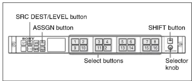
Assigning a source to a select button
1 Check that the SRC DEST/LEVEL button is lit in green. If it is not lit in green, press the SRC DEST/LEVEL button to make it light in green. 2 Turn the selector knob to display the source name to be set in the Preset block of the status display window.
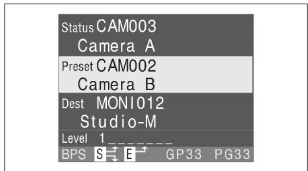
3 Press the select button to which you wish to set the source while holding the ASSGN button pressed.
The ASSGN button is lit in bright green while it is pressed. The selected source name appears on the select button.
The display in the status display window returns to that before Step 2.
Assigning a destination to a select button
1 Check that the SRC DEST/LEVEL button is lit in amber.
If it is not lit in amber, press the SRC DEST/LEVEL button to make it light in amber.
2 Turn the selector knob to display the destination name to be set in the Preset block of the status display window. 3 Press the select button to which you wish to set the destination while holding the ASSGN button pressed.
The ASSGN button is lit in bright green while it is pressed. The selected destination name appears on the select button.
The display in the status display window returns to that before Step 2.
Assigning a source and destination simultaneously
In the MD-selection system, a source and destination are assigned to a button as a pair.
1 Select a destination to be set.
The destination name appears in the Dest block of the status display window.
2 Select a source to be set by turning the selector knob.
The source name appears in the Preset block of the status display window.
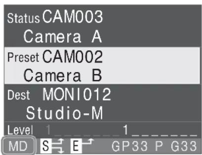
Multi-destination-selection system
3 Press the SHIFT button. 4 While holding the ASSGN button pressed, press a select button to which a source and destination are to be assigned.
The source and destination displayed in the status display window are assigned to the pressed select button, and the assigned source name appears.
The display in the status display window returns to that before Step 2.
Clearing the function assigned to a select button (V2.0 and above)
Source and destination functions assigned to select buttons can be cleared. Functions other than source and destination (TAKE, MONI, LEVEL, etc.) cannot be cleared.
Note
This function is disabled as default. To use this function, set it to be enabled at the control terminal
1 Display the function to be cleared on the select button.
Change the page group, page, source, and destination to display it.
2 Hold the ASSGN button pressed for more than 5 seconds.
The ASSGN button starts flashing in red.
The Preset block of the status display window is highlighted, and " " is displayed.
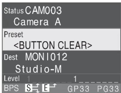
3 While holding the ASSGN button pressed, press a select button whose function is to be cleared.
The function assigned the pressed select button is cleared.
Assigning the color for a select button (V2.0 and above)
The color for a select button and for characters displayed on the button can be changed in combination. Up to 8 color patterns (PATTERN 1 to PATTERN 8) can be set at the control terminal. In the BPS selection system and MD selection system, any color pattern can be assigned to each select button. PATTERN 0 is the color pattern set at the factory.
Note
This function is disabled by default. To use this function, enable it at the control terminal.
1 Display the select button on which a color pattern is to be assigned.
Change the page group, page, source, and destination to display it.
2 Press the SHIFT button. 3 While holding the ASSGN button pressed, turn the selector knob.
The display changes to the preset display mode. The Preset block is highlighted, and “ ” and the color pattern number are displayed. The background color in the Preset block indicates the color of the button, and the character color indicates the color of the characters displayed on the button.
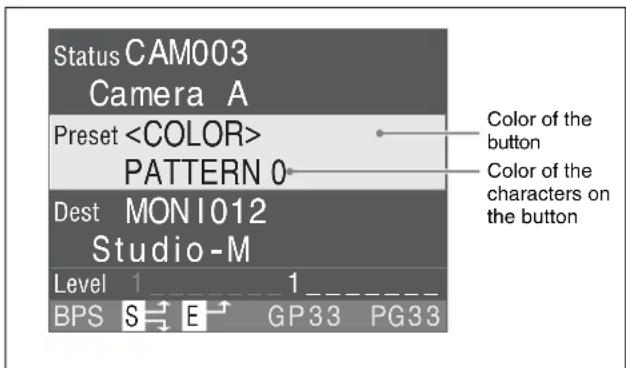
4 While holding the ASSGN button pressed, turn the selector knob to select the color pattern to be assigned. 5 When the color pattern you wish to assign appears, press a select button to which you wish to assign a color pattern while holding the ASSGN button pressed.
The color of the pressed button changes to the selected color pattern.
Various Functions
Breakaway Function
Different sources can be switched for levels. This is called the breakaway function.
When the breakaway function is used, the display of the source/destination select buttons is different from that when this function is not used. When IN001 to IN016 are assigned to select buttons 1 to 16 in the BPS-selection system, display examples are shown below.
When the breakaway function is not used
A single source is used for all the levels to be controlled.
| Level Source Destination |
| LEVEL 1 IN 11 OUT 3 |
| LEVEL 2 IN 11 OUT 3 |
| LEVEL 3 IN 11 OUT 3 |
![graph TD A["Source VTR"] --> B["Video: Level 1 IN 11"] A --> C["Audio channels 1/2: Level 2 IN 11"] A --> D["Audio channels 3/4: Level 3 IN 11"] B --> E["Video routing switcher OUT 3"] C --> F["Audio routing switcher OUT 3"] D --> G["Audio routing switcher OUT 3"] E --> H["Destination VTR"] F --> H…](/content/2026/07/1409310/images/051c9a2211023f221eefa2d0a331e2a84fae38ad1ae78cc9f132264c3e037101.jpg)
When the breakaway function is used
Different sources are used for each level.
| Level Source Destination |
| LEVEL 1 IN 11 OUT 3 |
| LEVEL 2 IN 14 OUT 3 |
| LEVEL 3 IN 16 OUT 3 |
![graph TD A["Source VTR"] --> B["Video: Level 1 IN 11"] B --> C["Audio routing switcher OUT 3"] C --> D["Destination VTR"] E["Audio source"] --> F["Audio channels 1/2: Level 2 IN 14"] F --> G["Audio channels 3/4: Level 3 IN 16"] G --> H["Audio routing switcher OUT 3"] H --> I["Destination VTR"] J["Di…](/content/2026/07/1409310/images/f64e1f507f72f573d7a9f34173f1f8a277d5ce59cc2d988a00ae56cba96625b8.jpg)
Switching using the Breakaway function
1 Press the SHIFT button.
2 Press the SRC DEST/LEVEL button to set the level selection mode.
The select buttons light in dark blue.

3 Press the select button to select the level. 4 Turn the selector knob to select a source.
The selected source appears in the Preset block of the status display window.
5 Press the TAKE button or selector knob.
The crosspoint for the level selected in Step 3 is switched.
What is Level
The routing switcher system switches multiple signals for one destination using the level function. Different kinds of signals such as SD video, HD video, audio, etc. are assigned to different levels, and they are switched using the level function.
The level function has two control modes: 8-level mode, which controls levels with 8 layers, and 16-level mode, which controls levels with 16 layers. The 8-level mode can control crosspoints of up to 1024 × 1024 on each layer, and the 16-level mode can control up to 1024 × 512 on each layer.
![graph TD A["1024 1 Sources"] --> B["Level 8"] B --> C{8 layers} C --> D["Level 1"] D --> E["Destinations (Level 1 to 8)"] E --> F["1024 × 1024"] G["1024 1 Sources"] --> H["Level 8"] H --> I{8 layers (Level 1 to 8)} I --> J["Level 1"] J --> K["Destination (Level 1 to 8)"] K --> L["1024 × 512"] M["102…](/content/2026/07/1409310/images/17be0a1f2c0950d941a8144521e2f97ac31468effd62dfbf3de53f3d1e98f483.jpg)
Phantom Function
If the phantom has been set on the control terminal, you can switch multiple crosspoints by pressing a single button.
This unit has three phantom functions: global phantom, local phantom, and destination offset local phantom. The phantom functions have the following features.
Local phantom
The local phantom allows you to switch multiple crosspoints by pressing a single button, or to switch crosspoints independently from destinations controlled on the unit. Up to 1024 crosspoints can be set for a phantom.
To execute phantom
Press the select button on which the phantom to be switched has been set. Crosspoints set on the pressed button are all switched.
Global phantom
The global phantom allows you to switch up to 2,800 crosspoints by pressing a single button. This function may be used to switch crosspoints defined for a phantom name with two or more units.
To execute phantom
Press the select button on which the phantom to be switched has been set. Crosspoints set on the pressed button are all switched.
Destination offset local phantom
The destination offset local phantom sets the destination of the local phantom to a substitute parameter such as (DST + *) where (*) is an offset value of the connector number of the destination. (DST) is automatically substituted with the connector number of the destination selected when phantom-switching. For example, if the destination is OUT005, the connector number of the destination is 015, and the offset value is 2 (* = 2), the destination 017 is switched.
To execute the destination offset local phantom, first select and check the destination.
Examples of this phantom are given below.
Example 1
To assign a source (audio source AUD007 for example) of a level to multiple sources of another level (video source IN001 and IN005 for example)
| Source name for each level | Setting of destination offset local phantom name | ||
| Source LEVEL1 LEVEL2 name | Phantom name | Desti- nation | Source Level |
| IN001 IN001 AUD007 IN001 | DST + 000 | IN001 10000000 | |
| DST + 000 AUD007 01000000 | |||
| IN005 IN005 AUD007 IN005 | DST + 000 | IN005 10000000 | |
| DST + 000 AUD007 01000000 | |||
Example 2
To set a pair of crosspoints (multiple audio channels, video key signal for example)
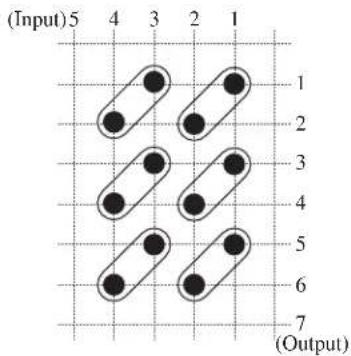
| Setting of destination offset local phantom name | |
| Phantom name Destination Source Level | |
| IN001 DST + 000 IN001 10000000 | |
| DST + 001 IN002 10000000 | |
| IN003 DST + 000 IN003 10000000 | |
| DST + 001 IN004 10000000 | |
To execute phantom
1 Select a base destination.
2 Press the select button on which the phantom name has been set.
Crosspoints of the sources set on the pressed button and the destination to which the offset value is added are switched.
Pages and Page Groups
In the BPS-selection system and MD-selection system, you can set multiple functions on 16 select buttons on the control terminal. The BKS-R6010 controls crosspoint switching according to these settings. One set of settings is made on one setting page of the control terminal, and up to 16 sets (16 pages) of settings can be set. For each page, a page name has been assigned.
The consecutive pages can be grouped, and a group name is assigned to each group on the control terminal. Up to 16 groups can be created.
The page to be displayed when the unit is turned on can be set at the control terminal (V2.0 and above).
![graph TD A["Page 1"] --> B["Page group 1"] C["Page 2"] --> D["Page group 1"] E["Page 3"] --> F["Page group 1"] G["Page 4"] --> H["Page group 2"] I["Page 5"] --> J["Page group 2"] K["Page 6"] --> L["Page group 3"] M["..."] --> N["..."] O["Page 16"] --> P["Page group n"]](/content/2026/07/1409310/images/a8097881f90902d70b9f441923383a3cf04fb3afc031be94f986c2e8716af272.jpg)
Selecting a page or page group
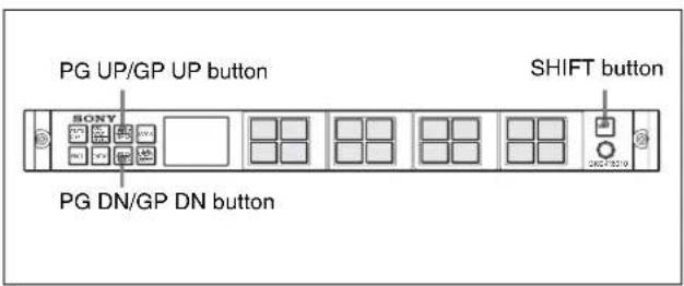
A page or page group displayed in the status display window is selected with the PG UP/GP UP or PG DN/GP DN button.

Selecting a page
Press the PG UP/GP UP or PG DN/GP DN button. The pressed button momentarily lights in bright green, and the displayed page changes. If the PG UP/GP UP button is pressed, the following page is displayed, and if PG DN/GP DN button is pressed, the previous page is displayed.
Selecting a page group
1 Press the SHIFT button.
The SHIFT button lights in bright green.
2 Press the PG UP/GP UP button or PG DN/GP DN button.
The SHIFT button goes dark, and the pressed PG UP/GP UP button or PG DN/GP DN button momentarily lights in bright green.
If the PG UP/GP UP button is pressed, the first page of the following page group is displayed, and if PG DN/GP DN button is pressed, the first page of the previous page group is displayed.
Monitoring Two Sources (Chop)
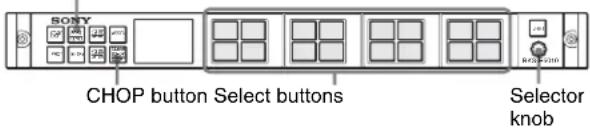
Two sources are switched alternately at a specified interval automatically. For phantom operation, the chop function is also enabled. The interval can be adjusted with the selector knob.
SRC DEST/LEVEL button
Switching sources
1 Press the SRC DEST/LEVEL button to set the destination selection mode. 2 Press a select button to select the destination.
The unit is in source selection mode.
3 Press a select button to select a source for Source 1. 4 Hold the CHOP button pressed for more than three seconds.
The CHOP button lights in green, and CHOP icon appears in the status display window.

5 Press a select button to select a source for Source 2.
Source 1 and Source 2 are switched alternately.
The method for selecting a destination or source varies depending on the selection system. If Phantom has been set, Phantom chop is executed.
To terminate Chop
Press the CHOP button.
To adjust the interval
Turn the selector knob. Turning it clockwise makes the interval longer, and counterclockwise makes it shorter.
Protecting a Destination from Being Switched
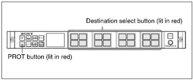
When Protection is set, switching of the source for the protected destination is disabled. If the source select button for a protected destination is pressed, the pressed button will light in red while being held pressed.

Setting the protection
1 Select a destination to be protected. 2 Press the PROT button.
The PROT button lights in green, and the destination selected in Step 1 is protected. A crosspoint for the destination cannot be switched.
The protect icon appears in the status display window.

Releasing the protection
The protection can be released only at the unit on which the protection was set. Normally, on the other units protection cannot be released. However, releasing the protection on other units may be enabled by a setting on the control terminal.
The control terminal can release the protection set on any unit.
1 Select a destination whose protection is to be released. 2 Press the PROT button.
The PROT button goes dark, and the protection is released.
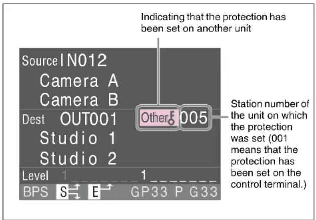
Protection set on another unit
If you select a destination to which protection has been set on another station, the pressed button and the PROT button light in red, and the icon for the protection set on the other station appears in the status display window.
Preventing Accidental Operations (Lock)
When the panel is locked, accidentally switching a crosspoint can be avoided.
If the button on the locked panel is pressed, the station number appears in the status display window.

Locking the panel
1 Press the SHIFT button.
The SHIFT button lights in bright green.
2 Press the CLEAR (CHOP)/LOCK button.
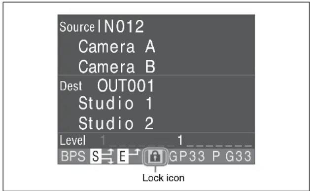
The SHIFT button goes dark, and the CLEAR (CHOP)/LOCK button lights in red (Lock mode). All buttons other than the CLEAR (CHOP)/LOCK button on the panel are disabled.
The lock icon appears in the status display window.
Releasing the Lock
1 Press the SHIFT button.
The SHIFT button lights in bright green.
2 Press the CLEAR (CHOP)/LOCK button.
The SHIFT button and the CLEAR (CHOP)/LOCK button go dark, and Lock mode is released. The lock icon in the status display window disappears.
Monitor Function
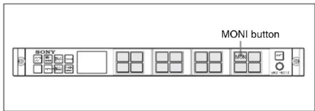
When the destination to be monitored has been specified on the control terminal, the monitor display panel automatically selects the source for that destination if the monitor function is ON (the select button assigned to the MONI button is selected).
With the conventional system, the monitor signal is returned to the input, as shown below, to monitor the destination. Such a process is not required for the monitor function, which uses no extra crosspoint, and eliminates signal delay in loopback.
An offset can be added to the automatically selected source, which provides various monitoring possibilities (e.g. monitoring an HD source that is down-converted to the D1 format).
![graph TD A["Source offset"] --> B["HD system"] B --> C["HD signal"] C --> D["Down convert"] D --> E["HD to D1"] E --> F["D1 signal"] F --> G["Standard system"] G --> H["Monitor display panel"] H --> I["Output"]](/content/2026/07/1409310/images/1f2eba1891296906f8c3f95ceffb88d42b9a011d68d7c37316a762873e434871.jpg)
1 Set the destination to be monitored on the control terminal. 2 Press the MONI button.
The source for the set destination is output to the monitor.
Monitoring the Input and Output Signals (V2.0 and above)
When the virtual monitor function is set at the control terminal, an input or output signal switched with this unit can be output to the connector that has been set as the monitor output connector at the control terminal.
For details on settings, refer to the System Setup Manual.
When the virtual monitor function has been set, the display on the status display window is as shown below.
When a source is selected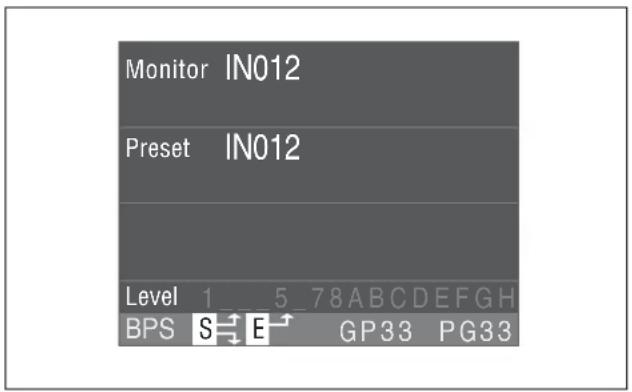
When a destination is selected
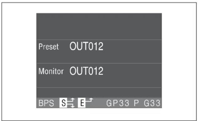
When a source or destination is selected, the selected source or destination is displayed in the Preset block of the status display window. Once the selection is registered by pressing the TAKE button, the selected source or destination is displayed in the Monitor block.
Note
In the MD selection system, the unit functions in the same way as in the BPS selection system if the virtual monitor function has been set.
Resetting
The BKS-R6010 can be reset with the buttons on the front panel.
Resetting the software
Hold the PROT button and ENTRY button pressed simultaneously for more than five seconds. RESET appears in the status display window, and the time to be restarted appears like 3, 2, 1 and 0. While resetting, the STATS DISP button flashes in red (V2.0 and above). When resetting is completed, RESET disappears.


Note
If you press the PROT button before the ENTRY button, the unit restarts with the panel protected.
Error Display
Error messages
While trouble occurs with the BKS-R6010, one of the following error messages appears in the status display window. An error message disappears within a few seconds. The message is also cleared by your pressing the CLEAR button. When the error message disappears, you can continue operation.
| Error messages Contents Remarks | ||
| Packet Error Reception | error on the S-BUS or Ethernet data link | If this occurs only once every several minutes, it is not a problem. Power source noise or an S-BUS remote cable longer than 500 m using BELDEN cable or equivalent may be the cause. If the same errors still occurs on this unit when used under conditions without the above causes, the trouble may be in this unit. |
| Communication Errora) | Communication error of the S-BUS or Ethernet data link | This may occur when the communication period is too long. The primary station (or subnet controller) may be turned off, or the remote cable may be disconnected. |
| Reset- Primary The primary station has been reset. | This occurs when the primary station is turned on, or when some trouble occurs in the S-BUS data link. | |
| Reset The unit is being reset. This appears when the unit is being reset by pressing the buttons on the front panel. | ||
| Not Found The name cannot be found. The designated description name or type name in the Keypad-selection system or TPN-selection system does not exist in the table. | ||
| Secret Source A source set as secret is to be selected. | A source set as secret cannot be selected on a unit other than the primary station. | |
| Protect Destination The destination is protected. The protected destination cannot be switched. In the Dest block of the status display window, the station number of the unit which has set the protection to the destination, is displayed. | ||
| Not Available Source The source is out of the available sources. | The source to be switched is not found within the range of the available sources or the destination for the source to be switched is disabled. The source cannot be switched. | |
| No Destination The destination has not been set. The designated destination has not been set. Change the selection or setting. | ||
| Control Level Error | All levels are not controllable. | All levels are set not to be controlled. |
a) "Communication Error" is displayed until normal communication status is retrieved.
Warning display (complying with V2.1 and above)
S (Lights in red)
This indicates that the cable is disconnected from the REMOTE 1 B connector or that the 75Ω terminator is removed from the REMOTE 1B connector when the unit functions as a subnet controller.
This is displayed until normal communication status is restored.
Specifications
REMOTE 1 A/B BNC type ×2
S-BUS
Data transfer method: BI-PHASE SPACE
Data transfer rate: 312.5 kbps/1,250 kbps
Signal transfer distance: 500 m (1,640 feet) (75Ω coaxial cable, BELDEN 8281 or equivalent)
REMOTE 2 D-sub 9-pin ×1
RS-422
Data transfer method: conforming to the EIA RS-422A
Data transfer rate: 38.4 kbps
RS232C D-sub 9-pin ×1
RS-232C
Data transfer method: 8-bit, No parity, No check
Data transfer rate: 38.4 kbps
TC IN BNC type ×1
NETWORK 100 BASE-TX: modular jack ×1
Operating temperature
5°C to 40°C (41°F to 104°F)
Power requirements 100 to 120 V AC (for the U.S.A. and Canada)
100 to 240 V AC (for the other countries)
50/60 Hz
Current consumption
0.7 to 0.3 A
Peak inrush current (1) Power ON, current probe method: 21 A (100 V), 40 A (240 V)
(2) Hot switching inrush current, measured in accordance with European standard EN55103-1: 5 A (230 V)
Dimensions (w/h/d) 440 × 43.6 × 155 mm
(17 3/8 × 1 3/4 × 6 1/8 inches)
Mass approx. 2.2 kg (4 lb 14 oz)
Accessories supplied
Operation and Installation Guide (1)
Software License Agreement (1)
Y bridge (1)
Touch plate (Concave surface type) (4)
Touch plate (Plain surface type) (4)
For the font set installed in this unit, refer to Readme.txt to be found on the CD-ROM supplied with a device such as an integrated routing system.
Design and specifications are subject to change without notice.
Note
Always verify that the unit is operating properly before use. SONY WILL NOT BE LIABLE FOR DAMAGES OF ANY KIND INCLUDING, BUT NOT LIMITED TO, COMPENSATION OR REIMBURSEMENT ON ACCOUNT OF THE LOSS OF PRESENT OR PROSPECTIVE PROFITS DUE TO FAILURE OF THIS UNIT, EITHER DURING THE WARRANTY PERIOD OR AFTER EXPIRATION OF THE WARRANTY, OR FOR ANY OTHER REASON WHATSOEVER.
The material contained in this manual consists of information that is the property of Sony Corporation and is intended solely for use by the purchasers of the equipment described in this manual.
Sony Corporation expressly prohibits the duplication of any portion of this manual or the use thereof for any purpose other than the operation or maintenance of the equipment described in this manual without the express written permission of Sony Corporation.

- WARNING
- AVERTISSEMENT
- FOR THE CUSTOMERS IN THE USA
- WARNING: THIS WARNING IS APPLICABLE FOR OTHER COUNTRIES
- FOR THE CUSTOMERS IN EUROPE
- FOR THE CUSTOMERS IN EUROPE, AUSTRALIA AND NEW ZEALAND
- FOR THE STATE OF CALIFORNIA, USA ONLY
- TABLE OF CONTENTS
- MANUAL LINE-UP
- OVERVIEW
- NOTES ON OPERATIONS
- LOCATIONS AND FUNCTIONS OF PARTS
- SWITCHING THE CROSSPOINT
- VARIOUS FUNCTIONS
- ERROR DISPLAY
- SPECIFICATIONS
- OPERATION MANUAL (THIS MANUAL)
- INSTALLATION MANUAL
- SYSTEM SETUP MANUAL
- MAINTENANCE MANUAL (OPTION)
- PROTOCOL MANUAL (OPTION)
- FEATURES
- STATUS DISPLAY WINDOW USING A COLOR TFT LCD
- MULTIFUNCTION SELECT BUTTONS USING A COLOR TFT LCD
- NOTE
- SELECT FUNCTION USING A SELECTOR KNOB
- SWITCHABLE FOR UP TO 1024 SOURCES AND 1024 DESTINATIONS
- BUTTONS TO SELECT SOURCES AND DESTINATIONS
- ROUTE FUNCTION TO SHOW EXPANDED SOURCES
- CONTROLLABLE UP TO 16 LEVELS 1)
- DIFFERENT SOURCES FOR LEVELS SELECTABLE (BREAKAWAY FUNCTION)
- MONITOR FUNCTION TO WATCH THE SELECTION FOR THE OTHER DESTINATION
- CHOP FUNCTION TO SWITCH TWO SOURCES ALTERNATELY
- SEVERAL CROSSPOINTS SWITCHABLE WITH THE TOUCH OF A BUTTON (PHANTOM FUNCTION OR SALVO FUNCTION)
- CONNECTABLE WITH A SINGLE CABLE
- CONTROL WITH ETHERNET
- DUAL CONTROL SYSTEM
- MULTIPLE NAMING USING ALIASES
- SELF-DIAGNOSTIC FUNCTION
- OPERATION ON VARIOUS VOLTAGES
- SOURCE OR DESTINATION NAME CHANGEABLE WITH THE SELECTOR KNOB
- EXPANDING THE NUMBER OF CONTROLLABLE SOURCES AND DESTINATIONS (COMPLYING WITH V2.0 AND ABOVE)
- WEB SETTING FUNCTION (COMPLYING WITH V2.0 AND ABOVE)
- TWO-BYTE CHARACTERS USABLE (COMPLYING WITH V2.0 AND ABOVE)
- USABLE AS A SUBNET CONTROLLER (COMPLYING WITH V2.1 AND ABOVE)
- VIRTUAL MONITOR FUNCTION (V2.0 AND ABOVE)
- SETTING THE SELECT BUTTON FUNCTIONS
- SELECTION SYSTEM
- BPS (DIRECT)-SELECTION SYSTEM
- MD (MULTI-DESTINATION)-SELECTION SYSTEM
- TPN (TYPE + NUMBER)-SELECTION SYSTEM
- KEYPAD-SELECTION SYSTEM
- CONTROL SYSTEM
- FUNCTIONS OF AN S-BUS SYSTEM
- USE OF MULTIPLE CONTROL UNITS (V2.0 AND ABOVE)
- ROUTE FUNCTION
- DESTINATION OFFSET ROUTE
- DESTINATION GROUP CONTROL
- ABOUT THE LCD PANELS
- ABOUT UNSTABLE DISPLAY ON LCD PANELS
- FRONT PANEL
- ① STATS DISP (STATUS DISPLAY) BUTTON
- ② SRC DEST/LEVEL (SOURCE/DESTINATION/LEVEL) BUTTON
- ③PG UP/GP UP (PAGE UP/PAGE GROUP UP) BUTTON
- ④ASSGN (ASSIGN) BUTTON
- CHANGING THE ASSIGNMENT OF SELECT BUTTONS
- SELECTING THE TYPE
- ⑤ STATUS DISPLAY WINDOW
- ⑥ SELECT BUTTONS
- SOURCE SELECTION FUNCTION (LIT IN GREEN)
- NOTES
- DESTINATION SELECTION FUNCTION (LIT IN AMBER)
- LEVEL SELECTION FUNCTION
- ⑦SHIFT BUTTON
- ⑧SELECTOR KNOB
- ⑨ CLEAR CHOP/LOCK BUTTON
- LOCK FUNCTION
- CHOP FUNCTION
- ⑩ PG DN/GP DN (PAGE DOWN/PAGE GROUP DOWN) SELECT BUTTON
- ⑪ ENTRY BUTTON
- ⑫ PROT (PROTECT) BUTTON
- REAR PANEL
- CAUTION
- STATUS DISPLAY WINDOW
- ICON
- BPS DISPLAY MODE
- PRESET DISPLAY MODE
- LEVEL DISPLAY MODE
- CONNECTOR DATA
- CHANGING THE DISPLAY BLOCK (V2.0 AND ABOVE)
- DISPLAY TRANSITION
- SELECTING THE SELECTION SYSTEM
- SWITCHING DIRECTLY (IMMEDIATE SWITCHING METHOD)
- SWITCHING USING THE TAKE BUTTON (PRESET SWITCHING METHOD)
- SWITCHING WITH THE SELECTOR KNOB
- GROUPING THE DESTINATIONS
- SWITCHING WITH THE SELECT BUTTONS
- TO MODIFY THE ENTERED NUMBER
- WHEN THE SELECTION IS INCORRECT
- DISPLAYING TYPE NAMES
- SWITCHING USING THE SELECTOR KNOB
- ENTERING THE DESCRIPTION NAME
- TO MODIFY THE ENTERED DATA
- TO CLEAR THE ENTERED DATA
- IF ENTERED DATA ARE NOT CORRECT
- SWITCHING A CROSSPOINT
- ASSIGNING FUNCTIONS TO THE SELECT BUTTONS
- ASSIGNING A SOURCE TO A SELECT BUTTON
- ASSIGNING A DESTINATION TO A SELECT BUTTON
- ASSIGNING A SOURCE AND DESTINATION SIMULTANEOUSLY
- CLEARING THE FUNCTION ASSIGNED TO A SELECT BUTTON (V2.0 AND ABOVE)
- ASSIGNING THE COLOR FOR A SELECT BUTTON (V2.0 AND ABOVE)
- BREAKAWAY FUNCTION
- WHEN THE BREAKAWAY FUNCTION IS NOT USED
- WHEN THE BREAKAWAY FUNCTION IS USED
- SWITCHING USING THE BREAKAWAY FUNCTION
- WHAT IS LEVEL
- PHANTOM FUNCTION
- LOCAL PHANTOM
- TO EXECUTE PHANTOM
- GLOBAL PHANTOM
- DESTINATION OFFSET LOCAL PHANTOM
- EXAMPLE
- PAGES AND PAGE GROUPS
- SELECTING A PAGE OR PAGE GROUP
- SELECTING A PAGE
- SELECTING A PAGE GROUP
- MONITORING TWO SOURCES (CHOP)
- SWITCHING SOURCES
- TO TERMINATE CHOP
- TO ADJUST THE INTERVAL
- PROTECTING A DESTINATION FROM BEING SWITCHED
- SETTING THE PROTECTION
- RELEASING THE PROTECTION
- PROTECTION SET ON ANOTHER UNIT
- PREVENTING ACCIDENTAL OPERATIONS (LOCK)
- LOCKING THE PANEL
- RELEASING THE LOCK
- MONITOR FUNCTION
- MONITORING THE INPUT AND OUTPUT SIGNALS (V2.0 AND ABOVE)
- RESETTING
- RESETTING THE SOFTWARE
- ERROR MESSAGES
- WARNING DISPLAY (COMPLYING WITH V2.1 AND ABOVE)
- S (LIGHTS IN RED)
Brand : SONY
Model : BKS-R6010
Category : Remote control