Tybox 5701 FP - Thermostat DELTA DORE - Free user manual and instructions
Find the device manual for free Tybox 5701 FP DELTA DORE in PDF.


| Product Type | Programmable Thermostat |
| Brand | Delta Dore |
| Model | Tybox 5701 FP |
| Dimensions (H x W x D) | Approx. 86 x 86 x 28 mm |
| Weight | Approx. 150 g |
| Power Supply | 2 x AA alkaline batteries (1.5V) |
| Display | LCD with backlight |
| Temperature Setpoint Range | 5°C to 30°C |
| Accuracy | ±0.5°C |
| Programmability | Daily/Weekly programmable (up to 4 time zones) |
| Communication | Wireless (868 MHz) with Tybox receivers |
| Protection Class | IP30 |
| Installation | Wall-mounted (screws and anchors included) |
| Maintenance | Clean with dry cloth; replace batteries when low |
| Spare Parts & Repairability | Batteries user-replaceable; consult professional for other repairs |
| General Information | Designed for heating control; compatible with various Delta Dore receivers |
Frequently Asked Questions - Tybox 5701 FP DELTA DORE
User questions about Tybox 5701 FP DELTA DORE
0 question about this device. Answer the ones you know or ask your own.
Ask a new question about this device
Download the instructions for your Thermostat in PDF format for free! Find your manual Tybox 5701 FP - DELTA DORE and take your electronic device back in hand. On this page are published all the documents necessary for the use of your device. Tybox 5701 FP by DELTA DORE.
USER MANUAL Tybox 5701 FP DELTA DORE
Tybox 5701 FP pilot wire pack
www.deltadore.com
Warning
The Tybox 5701 FP pack consists of a Tybox 5101 transmitter and a 6700 FP RF receiver.
There are two versions of the Tybox 5101 transmitter.
To find out the transmitter version, press the "mode" button for several seconds until the 1st configuration menu appears: CF00 or CF01.
| First version |  |  | Access the instructions |
| Second version |  |  | Access the instructions |
Tybox 57O1FP - 57O2FP

EN For detailed instructions: scan the QR code.
- Installation guidelines
- Pairing of a door/window magnetic contact,
- Pairing with the Tydom app
- Advanced features
- Help...
Fixed by screws or adhesive tabs


3 FP: Noir, Zwart, Schwarz, Nero, Black, Negro
2 Délest: Gris, Grijs, Grau, Griglo, Grey, Gris
- Association radio / Radioverbinding / Funkkopplung / Associazione radio / Wireless Association / Asociación vía radio


① To associate it, press the receiver button for 3 seconds, until the red LED flashes. Release.
② On the Tybox, briefly press a button to wake up the display, then press and hold both the mode and + buttons for 3 seconds.
The screen will display rF00. Release.
3 Press briefly on +. The screen flashes until rF is displayed depending on the number of associated receivers (eg. rF01 for a single receiver, rF02 for 2 receivers etc.).
4 Check that the LED of the receiver(s) is no longer flashing.
To exit the mode, briefly press the mode and + butt ons simultaneously.
Pairing a door/window magnetic contact / Pairing the Tydom app
Consult the additional instructions accessible via the QR code at the start of these instructions.

asociado,

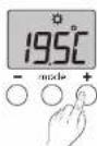

1 Press any button to activate the display. The current mode is displayed: On = Thermostat running, OFF = Stop. To switch from one mode to another, press
mode.
2 From On mode, wait a few seconds to display the set-point temperature and change it using + or -. Validation aft er 2 seconds if no butt ons are pressed.

1.1 Location....3
1.2 Wall mounting .... 3
1.3 Mounting on a base....3
- Installing the receiver....4
2.1 Location....4
2.2 Mounting / Connection....4
- Pairing the receiver to the transmitter.... 4
- Configuring your device .... 5
Menu CF00 Backlit display....5
Menu CF01 Correcting the temperature measured....5
Menu CF02 Locking the buttons 5
Menu CF03 Not used 5
Menu CF04 Adjustment of the frost protection setpoint ....5
- Pairing with the Tydom App 6
- Pairing with a window sensor.... 6
- Pairing with a repeater....6
- Troubleshooting....7
8.1 Deleting the pairing of the receiver with the thermostat....7
8.2 Removing pairings from the receiver....7
- Technical characteristics .... 7
Use
- Description 8
- Consultation or modification of temperatures....8
- Open window detection....8
- Operation with the Tydom application....8
- Operation with a load-shedder 9
- LED switch off mode....9
- Troubleshooting....10
7.1 What the receiver LEDs mean 10
7.2 Changing batteries ....11
INSTALLATION
1. Installing the transmitter
1.1 Location
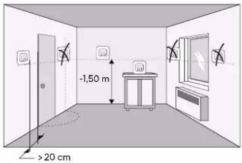
The thermostat can be mounted on the wall or placed on a piece of furniture in a room whose temperature is representative of the location's average temperature, with a recommended height of 1.5 m, and it should also be nowhere near any heat sources (fireworks, sunlight, etc.) or air flows (window, door, etc.).
IMPORTANT: Do not install the thermostat on a wall in contact with the outside or with an unheated room (e.g. garage, etc.)
1.2 Wall mounting
① Remove the front panel.
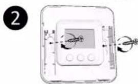
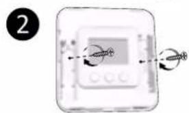
2 Secure the thermostat to the surface using suitable screws.
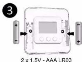
③ Insert the batteries
WARNING: make sure you insert the batteries facing the right way and that they are the right type (no lithium batteries).
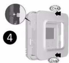
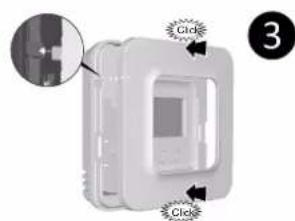
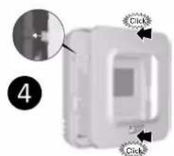
4 Replace the front panel.
1.3 Mounting on a base
① Remove the font panel.
② Insert the batteries.
WARNING: make sure you insert the batteries facing the right way and that they are the right type (no lithium batteries).
③ Replace the front panel.
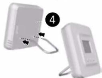
4 Insert the base into the back of the thermostat and place the device in the desire location (on a flat, non-metallic surface).

Wall mounting Mounting on a base



2. Installing the receiver
2.1 Location
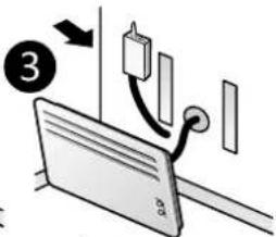
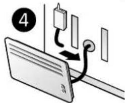
The antenna of the receiver must be clear of any metallic surface.
2.2 Mounting / Connection
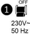
① First of all, switch off the power to your setup.
② The receiver can be secured by suitably sized screws or by adhesive (supplied).
③ You must make sure you comply with the wire colours when wiring.
Blue: Neutral
Brown: Phase
Black: Pilot wire
Grey: control by load-shedder
④ Once the receiver is connected, turn on the power to your setup.
Important:
- If there is no load-shedder, the grey wire cannot be connected, however, it is preferable that it be electrically isolated (on a terminal block, for example).
- The power cable for this product cannot be replaced; if the cable is damaged, please contact your reseller.

3. Pairing the receiver to the transmitter

The first time you power up, the green LED light on the receiver flashes rapidly, indicating that it has not been paired.
① To pair it, press the receiver button for 3 seconds, until the red LED flashes. Release the button.
② On the Tybox, press and hold both the mode and + buttons for 3 seconds. The screen will display rF00. Release the button.
3 Press briefly on +. The screen flashes until rF is displayed depending on the number of paired receivers (eg. rF01 for a single receiver, rF02 for 2 receivers etc.).
4 Check that the LED of the receiver(s) is no longer flashing. To exit the mode, simultaneously and briefly press the mode and + buttons.
4. Configuring your device

① Press any button to activate the screen.
② Press mode for 5 seconds until CF00 is displayed.
③ Press + or - to adjust the setting, and on mode to move to the next menu.
4 Press mode for 5 seconds to exit the configuration menu or, after a period of 2 minutes without activity, the Tybox validates the change of parameter and returns to standby.
Menu CF00 Backlit display
Default setting: Back-lighting activated
| ☐ | Deactivated |
| I | Activated (automatic switch-off) |
Menu CF01 Correcting the temperature measured
This menu is used to correct any difference you have noticed between the displayed temperature and the measured temperature.
Example: If the temperature displayed by the device is 19° C and the measured temperature is 20° C, input +1°C then confirm using OK. In order to change this setting, the unit
| Adjusts from -5°C to 5°C, in increments of 0.1°C. |
In order to change this setting, the unit must have been running for at least 2 hours beforehand.
Default setting: 0°C
Menu CF02 Locking the buttons
This menu allows you to prohibit any changes (settings, set point, mode).
Default setting: Authorised changes
| ☐ | No locking |
| I | Locking active |
If locked, the screen will display "----". To temporarily unlock, simultaneously press and hold the + and - buttons for 5 seconds.
Menu CF03 Not used
Please leave the setting at 00.
Menu CF04 Adjustment of the frost protection setpoint
This menu allows you to set the Frost protection set point temperature (from 5°C to 16°C). Default setting: 7°C
Adjusts from +5°C to +16°C, in increments of 0,5°C.
5. Pairing with the Tydom App
Launch the Tydom app from your smartphone or tablet, then:
Settings -> My devices -> Add device -> Heating -> Electrical -> Tybox 5701FP (+ RF6700FP) ... and follow the instructions.
For more information, refer to the section § "Operation with the Tydom application".
6. Pairing with a window sensor
Pairing with a window sensor means you can switch the heating to Frost Protection if a window opens (in the 10 seconds that follow).

1 Press the receiver button for 3 seconds until the red LED flashes.

② Briefly press the detector button.

③ Make sure that the receiver LED has stopped flashing.
7. Pairing with a repeater
If the radio range is too weak and the transmitter cannot be moved closer to the receiver, you can add an X3D radio repeater to your setup (example: ERX 2000).

1 Press the ERX 2000 receiver button for 3 seconds until the red LED flashes. Release.

2 On the Tybox, briefly press a button to wake up the display, then press and hold both the mode and + buttons for 3 seconds. The screen displays rFxx (depending on the number of associated products). Release.
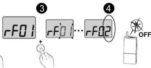
3 Press briefly on +. The screen flashes until rF is displayed depending on the number of associated receivers and repeaters (4) (e.g. rF02 for 1 receiver and 1 repeater). Check that the repeater's LED is no longer flashing.
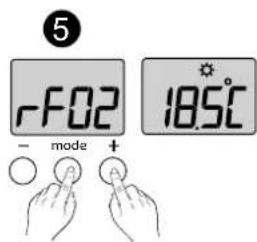
5 To exit the mode, briefly tap the mode and + buttons simultaneously.
To verify the number of associated repeaters:


On the Tybox, briefly press a button to wake up the display, then press and hold both the mode and + buttons for 3 seconds. The screen displays rFxx (depending on the number of associated products). Release.


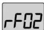
2 Press and hold mode for 3 seconds. The screen displays rP depending on the number of associated repeaters. (eg: rP01 for 1 repeater).
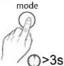
③ To exit:
- return to the rFxx menu, press mode for 3 seconds, - return to the initial display, briefly press the mode and + buttons simultaneously.
8. Troubleshooting
8.1 Deleting the pairing of the receiver with the thermostat In the event of a fault, you may have to unpair a product and/or repair a new one.
Wireless resetting of the transmitter
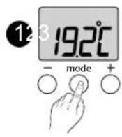


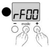

① On the Tybox, briefly press a button to wake up the display, then press and hold both the mode and + buttons for 3 seconds.
2 The screen displays rF-- depending on the number of associated receivers (e.g.: rF01 for a single receiver, rF02 for 2 receivers etc...). Press - for 3 seconds to confirm the reset. The screen displays rF00.
3 Briefly press the mode and + buttons at the same time. The screen displays dF 0 (transmitter not yet associated).
8.2 Removing pairings from the receiver
If the receiver is supplied with power and is within the wireless range of the transmitter at the time of the reset, the transmitter will also be deleted on the receiver.
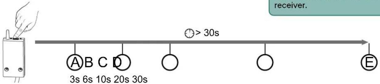
The deletion of wireless pairings with the receiver is carried out by holding down the button. The LED will cycle through the various states.
Ⓐ: The LED flashes red. The receiver is in pending pairing mode.
⑧: The red LED is on and steady. The receiver is in "LED switch off" mode.
©: The red LED flashes rapidly. The receiver is waiting for pairing with an opening detector to be deleted (confirm by briefly pressing the opening detector button).
(D) : The red LED turns off. All pairings with the receiver are now removed.
⑤: If you hold down the button for 30 seconds, the LED flashes quickly 3 times. The receiver is fully reset (back to factory settings).
9. Technical characteristics
TYBOX 5101 thermostat
• Power supply using 2 batteries: 2x1.5V Alkaline - Type LR03-AAA
• Class III insulation
• X3D transmission frequency: 868.7 MHz to 869.2 MHz
• Maximum wireless power < 10 mW
• Category II receiver
- Wireless range of 300 metres outside, varies depending on the paired equipment (the range can vary depending on the setup conditions and the electromagnetic environment).
• Wall-mounted or on base
• Dimensions: 80 x 84 x 21 mm
• Protection Class: IP 20
• Installation in an environment with normal pollution levels
• Storage temperature: -10°C/+70°C
- Operating temperature from -10°C / + 40°C
RF 6700 FP receiver
• 230 V\~ +/-10%, 50 Hz power supply
• Consumption: 0.4 W
• Class II insulation
- Pilot wire output (Comfort/Shutdown) 100 mA max., 230V - Type I.Y
- Load-shedding input (115V or 230V)
• Cable diameter 7mm +/- 0.4mm
• X3D transmission frequency: 868.7 MHz to 869.2 MHz
• Maximum wireless power < 10 mW
• Category II receiver
- Wireless range of 300 metres outside, varies depending on the paired equipment (the range can vary depending on the setup conditions and the electromagnetic environment).
• Dimensions: 54 x 102 x 20 mm
• Protection rating: IP44
- Vertical positioning of the product
- Storage temperature: -10°C / + 70°C
- Operating temperature from -10°C / + 40°C
• Ball test temperature: 75°C (Housing),
• Rated impulse voltage: 2,500V
1. Description

Ⓐ Temperature display
B Select the mode
© Adjustment buttons
(D) Request in progress
E Heat mode
F Battery level indicator
2. Consultation or modification of temperatures
IMPORTANT: The radiator must be in automatic mode (AUTO, PROG ...), with its Comfort temperature set to the maximum.


2
On the receiver:
Green LED illuminated = power supply OK
Red LED illuminated = heating request pending
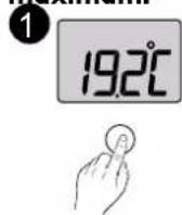
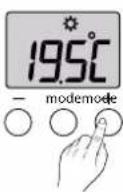
① Press any button to activate the screen. The current mode is displayed:
ON = Thermostat on, OFF = Off.
To switch from one mode to another, press mode.
② From ON mode, wait a few seconds to display the set-point temperature and change it using + or -.
Validation after 2 seconds if no buttons are pressed.
3. Open window detection

If you have linked a motion detector to your setup.
When a window is opened, after 10 seconds the screen indicates:
Frost protection setpoint (7°C by default) alternating with OPEn.
4. Operation with the Tydom application
| Features Via the Tydom | App |
| Programming Yes | |
| Setting the temperatures | Yes(temperatures programmed in the app: special events, overrides, scenario) |
| Pre-heat function | YesYour equipment automatically determines the start-up time in order to reach the temperature at the programmed time. |
| Absence Mode / Heat Mode Yes | |
| Deactivating the system Yes |

In "absence" mode, the screen of the Tybox indicates:
Frost protection setpoint (7°C by default) alternating with Ab.
In "system shutdown mode", the Tybox screen indicates OFF.
5. Operation with a load-shedder
If a load-shedder is connected to the receiver, the heating will switch to Off during load-shedding requests. When load-shedding is in progress, the green LED on the receiver flashes.
6. LED switch off mode
When the function for switching off the LEDs is active:
- When powering up (or restoring power), the LEDs are active.
- If the button has not been pressed after one minute, the LEDs switch off.
- A press of the button will authorise the illumination of the LEDS for one minute.
The backup and default pilot wire modes will still be signalled.
To enable/disable the function:
Press for 6 seconds, until the LED switches on without flashing.

① Press the receiver button for 6 seconds until the red LED is on and steady.
Release the button.
② The LED is flashing:
1 flash: function disabled
2 flashes: function active.
A short press enables you to switch from one to the other.
③ A 3-second press validates the selection and exits the mode.
The LEDs switch off after 1 minute of inaction.
7. Troubleshooting
7.1 What the receiver LEDs mean
| Signal type Diagnosis/Solutions | |
| The green light is constantly on | Power supply is on. |
| The red light is constantly on | The receiver is requesting heating (pilot wire output = Comfort) |
| The red LED is slowly flashing | The receiver is pending pairing.Please refer to the “Pairing the receiver to the transmitter”. chapter |
| The red LED is flashing quickly | The deletion of the pairing between the receiver and a door/window sensor is pending.Please refer to the section entitled “Removing pairings from the receiver”. |
| The green LED is flashing | The receiver isn’t paired.Please refer to the “Pairing the receiver to the transmitter” chapter. |
| The 2 LEDs are flashing simultaneously | No signal has been received by the thermostat for 1 hour.The receiver is operating in backup mode (*).Turn the thermostat on by pressing a button.If the problem persists, make sure that the transmitter is not too far away and that you have followed the mounting/placement instructions properly.Note: after a power cut, the receiver operates in emergency mode (*) for as long as it has not received any information from the thermostat, for up to max. 5 minutes. |
| The green LED is flashing slowly | Load-shedding in progress: you are exceeding the consumption allowed in your power subscription. The receiver starts up again automatically after a certain period of time. If an energy manager is also part of the installation, check that is permanently set to Comfort mode. |
| Both LEDs quickly flash simultaneously. | Pilot wire fault.Disconnect the power to the installation and check the cabling or contact your installer. |
(*) Function in backup mode:
- When switching to backup mode, if the receiver control was off, it stays off otherwise it switches to emergency Frost protection.
- In this Frost Protection Backup (or Stop) mode, pressing the button authorises a manual override.
3 control types are available and are shown by the LEDs flashing:
- 1 flash: Off,
- 2 flashes: Emergency frost protection (heating 15% of the time),
- 3 flashes: Emergency Comfort (heating 75% of the time), 24 hour timer.
You can switch from one to the other by briefly pressing the button.
7.2 Changing batteries
• The symbol appears.
You have approximately 1 month to replace them (two 1.5 V alkaline batteries, either LR03 or AAA).
WARNING: make sure you insert the batteries facing the right way and that they are the right type (no lithium batteries).

Frequently Asked Questions (FAQ)
- For the optimal operation of your installation, you must disable the opening detection and presence function on the radiator(s), if present.
- It is possible that the "DEL" (load-shedding in progress) screen will appear on the LCD screen of certain radiators when the STOP command is issued. This is normal with our product.
• The screen displays:
Your Tybox transmitter is temporarily awaiting feedback.
• The screen displays:
Your Tybox transmitter has just "woken up" (exit standby).
• The screen displays "dF 0".
Your Tybox transmitter is not associated to a heating receiver.
• The screen displays "dF 9".
Wireless fault during wireless communication (turning on, sending a command).
- You do not have access to the settings
The buttons are locked. The screen displays “----”. To unlock them periodically (until the next time the system is in standby), press the + and - buttons simultaneously for 5 seconds.
![graph LR A["18.5°C"] --> B["- mode +"] B --> C["lock"] C --> D[">5s"] D --> E["18.5°C"]](/content/2026/07/1409119/images/e2f922d5fa08eb7a953897d3d32479885301e3381129d4c46f3efa82aa461092.jpg)
To unlock them permanently, consult the CF02 configuration menu.
END OF TYBOX 5701/5702 FP WEB INSTRUCTIONS 2nd VERSION.
Tybox 57O1FP - 57O2FP - RF67OOFP

FR Guide de démarrage rapide
NL Spelstartgals
NE Sheistarglus
DE Schnellstartanleitung
IT Guida rapida
EN Quick start guide
ES Guía de inicio rápido
| Tybox 5101 RF 6700FP | ||
| 2 x 1,5V LR03 - AAA Alkaline | 230 V- +/-10%, 50 Hz0,4W | |
| 868,7 MHz -> 869.2 MHz (EN 300 220) - 300 m max.Maximum wireless power < 10 mW -Category 2 receiver | ||
| Output / | 100 mA max., 230V - Type 1.YFil pilote (Comfort/Arrêt) - Pilot wire (Comfort/Stop) | |
| Input | Delestage/ Delesteur/ Lastabwurf / Internuzione /Load shedding (option) / Racionalizado115V or 230V | |
| °C | -10°C / +40°C | |
| 80 x 84 x 21 mm 54 x 140 x 25 mm | ||
| IP 20 IP44 | ||
| Température d'essai à la bille : 75°CVerwekingspunt can kogelmethode: 75°CTemperatur Kugeldruckprüfung: 75°CTemperatura per la prova della biglia: 75°CBall test temperature: 75°C.Temperatura máxima soportada en laboratorio: 75°C | ||
| Tension assignée de choc : 2500VToegekende stoatspanning: 2500 VBemessungsstoßspannung: 2500 VTensione nominala di resistenza alla sovratensione: 2500 VRated impulse withstand voltage: 2500VTensión nominal de choques: 2500V | ||
CE
www.deltadore.com
Tybox 5701 FP Tybox 5702 FP
Tybox 5101


RF 6700 FP Tybox 5101


2 x RF 6700 FP
1. Notice web détaillée / Gedetailleerde gebruiksaanwijzing online / Detaillierte Web-Anleitung / Istruzioni web dettagliate / Detailed instructions / Manual de instalación en la página web

EN For detailed Instructions: scan the QR code.
- Installation guidelines
- Pairing of a door/window magnetic contact,
- Pairing with the Tydom app
- Advanced features
Help...
Fixed by screws or adhesive tabs


3 FP: Noir, Zwart, Schwarz, Nero, Black, Negro
2 Délest: Gris, Grijs, Grau, Griglo, Grey, Gris
3. Association radio / Draadloze verbinding / Funkzuordnung / Associazione radio / Radio association / Asociación vía radio

2
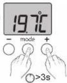


EN The first time you power up, the green LED on the receiver flashes rapidly, indicating that it has not been paired. 1 To pair it, press the receiver button for 3 seconds, until the red LED flashes. Release the button. 2 On the Txbox, simultaneously press both the mode and + buttons for 3 seconds.
The screen will display rF00. Release the buttons.
3 Press briefly on +. The screen flashes until rF is displayed, depending on the number of paired receivers (4) (e.g.: rF01 for a single receiver, rF02 for 2 receivers etc...).
5 Check that the LED on the receiver is no longer flashing.
To exit the mode, simultaneously and briefly press the mode and + buttons.
Pairing a door/window magnetic contact / Pairing the Tydom app
Consult the additional instructions accessible via the QR code at the start of these instructions.
EN ① Press any button to activate the display screen. ② Press mode for 10 seconds, until CF01 is displayed.
3 Press + or - to adjust the setting, or press mode to
move to the next menu.
CF01: Correction of the measured temperature
CF02: Button lock
CF03:00.Leave the setting at 00.
EN IMPORTANT: The radiator must be in automatic mode (AUTO, PROG, ⏻...), with Its Comfort temperature set to the maximum
Temperature set to the maximum.
Press any button to activate the display screen. The
current mode is displayed:
ON = ready for operation. Stop.
To change it, press mode.
2 From ON mode, press + or - to display the temperature
setting and modify it.</2>
③ Press mode or wait 5 seconds to exit.
When switching from ⏻ mode to ON mode, the setting returns to its default value: 20°C.
Indicates that the system is in Frost Protection mode (7°C, cannot be modified). Example: open window On the receiver;
Green LED illuminated = power supply OK Red LED illuminated = heating request pending
1.1 Location....2
1.2 Wall mounting 2
1.3 Mounting on a base....2
- Installing the receiver.... 3
2.1 Location....3
2.2 Mounting / Connection....3
- Wireless pairing .... 3
- Configuring your device 4
Menu CF01 - Correcting the temperature measured....4
Menu CF02 Locking the buttons ....4
Menu CF03 Not used....4
- Pairing with the Tydom app.... 5
- Pairing with a window sensor.... 5
- Pairing with a repeater.... 5
- Troubleshooting....6
8.1 Deleting the pairing of the receiver with the thermostat, Tydom or window sensor....6
8.2 Removing pairings from the receiver....6
- Technical characteristics 6
Use
- Description 7
- Consultation or modification of temperatures....7
- Open window detection....7
- Operation with a load-shedder 8
- Operation with the Tydom application.... 8
- LED switch off mode 8
- Troubleshooting....9
7.1 What the receiver LEDs mean 9
7.2 Changing batteries ....10
INSTALLATION
1. Installing the thermostat
1.1 Location
The thermostat can be mounted on the wall or placed on a piece of furniture in a room whose temperature is representative of the location's average temperature, with a recommended height of 1.5 m, and it should also be nowhere near any heat sources (fireworks, sunlight, etc.) or air flows (window, door, etc.).
IMPORTANT: Do not install the thermostat on a wall in contact with the outside or with an unheated room (e.g. garage, etc.)
1.2 Wall mounting
① Remove the front panel.
2 Secure the thermostat to the surface using suitable screws.
③ Insert the batteries
WARNING: make sure you insert the batteries facing the right way and that they are the right type (no lithium batteries).
4 Replace the front panel.
1.3 Mounting on a base
1 Remove the font panel.
② Insert the batteries.
WARNING: make sure you insert the batteries facing the right way and that they are the right type (no lithium batteries).
③ Replace the front panel.
4 Insert the base into the back of the thermostat and place the device in the desire location (on a flat, non-metallic surface).
Wall mounting Mounting on a base




2. Installing the receiver
2.1 Location
The antenna of the receiver must be clear of any metallic surface.
2.2 Mounting / Connection
① First of all, switch off the power to your setup.
② The receiver can be secured by suitably sized screws or by adhesive (supplied).
③ You must make sure you comply with the wire colours when wiring.
Blue: Neutral
Brown: Phase
Black: Pilot wire
Grey: control by load-shedder
4 Once the receiver is connected, turn on the power to your setup.
Important:
- If there is no load-shedder, the grey wire cannot be connected, however, it is preferable that it be electrically isolated (on a terminal block, for example).
- The power cable for this product cannot be replaced; if the cable is damaged, the device must be disposed of.





3. Wireless pairing

The first time you power up, the green LED light on the receiver flashes rapidly, indicating that it has not been paired.
① To pair it, press the receiver button for 3 seconds, until the red LED flashes. Release the button.
② On the Tybox, press and hold both the mode and + buttons for 3 seconds.
The screen will display rF00. Release the button.
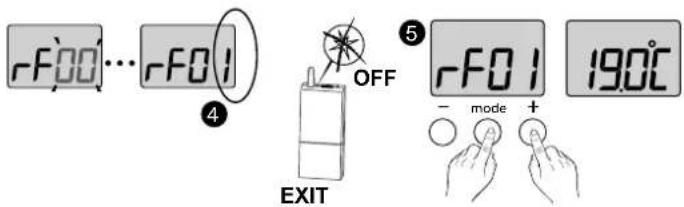
③ Press briefly on +. The screen flashes until rF is displayed depending on the number of paired receivers(④) (eg. rF01 for a single receiver, rF02 for 2 receivers etc.).
⑤ Check that the LED of the receiver(s) is no longer flashing.
To exit the mode, simultaneously and briefly press the mode and + buttons.
4. Configuring your device
![graph LR A["190°C"] --> B["CF01"] B --> C["+ 5°C"] C --> D["00°C"] D --> E["- 5°C"] E --> F["CF02"] F --> G["+ 01"] G --> H["00"] H --> I["CF03"] I --> J["00"] J --> K["190°C"] style A fill:#f9f,stroke:#333 style K fill:#f9f,stroke:#333](/content/2026/07/1409119/images/bb5ca347bc2ecfbdaf84fa5f0791e950095c1c7fb524e1b299a257883c31c98a.jpg)
① Press any button to activate the display screen.
② Press mode for 10 seconds until CF01 is displayed.
3 Press + or - to adjust the setting, and on mode to move to the next menu.
Menu CF01 - Correcting the temperature measured
This menu is used to correct any difference you have noticed between the displayed temperature and the measured temperature.
Example: If the temperature displayed by the device is 19° C and the measured temperature is 20° C, input +1°C then confirm using OK.
Default setting: 0°C
| Adjusts from -5°C to 5°C, in increments of 0.1°C. |
In order to change this setting, the unit must have been running for at least 2 hours beforehand.
Menu CF02 Locking the buttons
This menu allows you to prohibit access to the use of the buttons. Default setting: changes authorised
| ☐ | Access authorised |
| I | Access prohibited |
If locked, the screen will display “----”. To unlock, simultaneously press and hold the + and - buttons for 10 seconds.
Menu CF03 Not used
Please leave the setting at 00.
5. Pairing with the Tydom app
Launch the Tydom app from your smartphone or tablet, then:
Settings -> My devices -> Add device -> Heating -> Electrical -> Tybox 5701FP (+ RF6700FP) ... and follow the instructions.
For more information, refer to the section § "Operation with the Tydom application".
6. Pairing with a window sensor
Pairing with a window sensor means you can switch the heating to Frost Protection if a window opens (in the 10 seconds that follow).
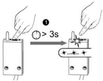
① Press the receiver button for 3 seconds until the red LED flashes.
② Briefly press the detector button.
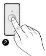
③ Make sure that the receiver LED has stopped flashing.

7. Pairing with a repeater
If the radio range is too weak and the transmitter cannot be moved closer to the receiver, you can add an X3D radio repeater to your setup (example: ERX 2000).

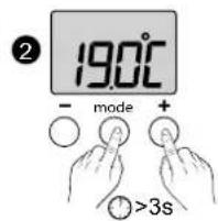
1 Press the ERX 2000 receiver button for 3 seconds until the red LED flashes. Release the button.
② On the thermostat, press and hold both the mode and + buttons for 3 seconds..
The screen displays rF0x (depending on the number of paired products). Release the button.
③ Press briefly on +. The screen flashes until rF is displayed depending on the number of paired receivers and repeaters (4) (e.g. rF02 for 1 receiver and 1 repeater).
③ Make sure that the repeater LED is no longer flashing.
To exit the mode, briefly tap the mode and + buttons simultaneously.
8. Troubleshooting
8.1 Deleting the pairing of the receiver with the thermostat,
Tydom or window sensor
In the event of a fault, you may have to unpair a product and/or repair a new one.
In the first instance, you should delete the receiver from the transmitter (Thermostat, Tydom, etc) as deletion performed on the receiver will not be synchronised with all transmitters.
Unpairing the receiver from the thermostat
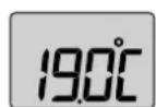


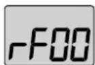

① On the thermostat, press and hold both the mode and + buttons for 3 seconds..
The screen will display rF01.
Release the button.
② Press the button - for 3 seconds until the screen displays rF00. Release the button.
To exit the mode, press the Mode and + buttons simultaneously.
8.2 Removing pairings from the receiver

The deletion of wireless pairings with the receiver is carried out by holding down the button.
The LED will cycle through the various states.
Ⓐ: The LED flashes red. The receiver is in pending pairing mode.
⑧: The red LED is on and steady. The receiver is in LED switch off mode.
©: The red LED flashes rapidly. The receiver is waiting to delete the pairing with a door/window magnetic contact (check on the device you want to be unpaired).
(D) : The red LED turns off. All pairings with the receiver are now removed.
⑤: If you hold down the button for 30 seconds, the LED flashes quickly 3 times.
The receiver is fully reset (back to factory settings).
9. Technical characteristics
TYBOX 5101 thermostat
• Power supply using 2 batteries:
2x1.5V Alkaline - Type LR03-AAA
• Class III insulation
• X3D transmission frequency: 868.7 MHz to 869.2 MHz
• Maximum wireless power < 10 mW
• Category II receiver
- Wireless range of 300 metres outside, varies depending on the paired equipment (the range can vary depending on the setup conditions and the electromagnetic environment).
• Wall-mounted or on base
• Dimensions: 80 x 84 x 21 mm
• Protection Class: IP 20
• Installation in an environment with normal pollution levels
• Storage temperature: -10°C/+70°C
- Operating temperature from -10°C / + 40°C
RF 6700 receiver
• Power supply 230 V -, 50 Hz
- Consumption: 0.4 W
• Class II insulation
- Pilot wire output (Comfort/Shutdown) 100 mA max., 230V - Type I.Y
- Load-shedding input (45V or 230V)
• Cable diameter 7mm +/- 0.4mm
• Vertical positioning of the product
• X3D transmission frequency: 868.7 MHz to 869.2 MHz
• Maximum wireless power < 10 mW
- Category II receiver
- Wireless range of 300 metres outside, varies depending on the paired equipment (the range can vary depending on the setup conditions and the electromagnetic environment).
• Dimensions: 54 x 140 x 25 mm
• Protection Class: IP 44
• Storage temperature: -10°C /+70°C
- Operating temperature from -10°C / + 40°C
• Ball test temperature: 75°C (Housing),
• Rated impulse voltage: 2,500V
1. Description

Ⓐ Temperature display
B Select the mode
© Adjustment buttons
2. Consultation or modification of temperatures
IMPORTANT: The radiator must be in automatic mode (AUTO, PROG①...), with its Comfort temperature set to the maximum.

1 Press any button to activate the screen. The current mode is displayed: ON = ready for operation, ☑ Stop.
To change the mode, press mode.
② From the ON mode, press + or - to display the temperature and change it.
③ Press mode or wait for 5 seconds to exit.
When switching over from the ⬆mode to the ON mode, the setting's default value is restored: 20°C.
On the receiver:
Green LED illuminated = power supply OK
Red LED illuminated = heating request pending
3. Open window detection

You have paired a window sensor to your setup.
In the case of an open window, the adjacent screen (----) indicates that the system is in Frost Protection mode (7°C, cannot be adjusted), unless it is shut down.
4. Operation with a load-shedder
If a load-shedder is connected to your receiver:
- switch heating off if load-shedding is requested.
When load-shedding is in progress, the green LED on the receiver flashes.
5. Operation with the Tydom application
Your RF6700 receiver can be paired using the TYDOM application.
| Features Via the Tydom app | |
| Programming Yes | |
| Setting the temperatures | Yes(temperatures programmed in the app: special events, overrides, scenario) |
| Pre-heat function | YesYour equipment automatically determines the start-up time in order to reach the temperature at the programmed time. |
| Absence mode Yes | |
6. LED switch off mode
When the function for switching off the LEDs os active:
- When powering up (or restoring power), the LEDs are in their "In progress" state.
- If the button has not been pressed after one minute, the LEDs switch off.
- A press of the button will authorise the illumination of the LEDS for one minute.
The backup and default pilot wire modes will still be signalled.
To enable/disable the function:
Press for 6 seconds, until the LED switches on without flashing.

① Press the receiver button for 6 seconds until the red LED is on and steady.
Release the button.
② The LED is flashing:
1 flash: function disabled
2 flashes: function active.
A short press enables you to switch from one to the other.
③ A 3-second press validates the selection and exits the mode.
The LEDs switch off after 1 minute of inaction.
7. Troubleshooting
7.1 What the receiver LEDs mean
| Signal type Diagnosis/Solutions | |
| The green light is constantly on | Power supply is on. |
| The red light is constantly on | The receiver is requesting heating (pilot wire output = Comfort) |
| The red LED is slowly flashing | The receiver is pending pairing.Please refer to the “Wireless pairing”. chapter |
| The red LED is flashing quickly | The deletion of the pairing between the receiver and a door/window sensor is pending. |
| The green LED is flashing | The receiver isn't paired.Please refer to the "Wireless pairing" chapter. |
| The 2 LEDs are flashing simultaneously | No signal has been received by the thermostat for 1 hour.The receiver is operating in backup mode (*).Turn the thermostat on by pressing a button.If the problem persists, make sure that the transmitter is not too far away and that you have followed the mounting/placement instructions properly. |
| The green LED is flashing slowly | Load-shedding in progress: you are exceeding the consumption allowed in your power subscription. The receiver starts up again automatically after a certain period of time. If an energy manager is also part of the installation, check that is permanently set to Comfort mode. |
| Both LEDs quickly flash simultaneously. | Pilot wire fault.Disconnect the power to the installation and check the cabling or contact your installer. |
(*) Function in backup mode:
- When switching to backup mode, if the receiver control was off, it stays off otherwise it switches to emergency Frost protection.
- In this Frost Protection Backup (or Stop) mode, pressing the button authorises a manual override.
3 control types are available and are shown by the LEDs flashing:
- 1 flash: Off,
- 2 flashes: Emergency frost protection (heating 15% of the time),
- 3 flashes: Emergency Comfort (heating 75% of the time), 24 hour timer.
You can switch from one to the other by briefly pressing the button.
7.2 Changing batteries
- The symbol appears.
You have approximately 1 month to replace them (two 1.5 V alkaline batteries, either LR03 or AAA).
WARNING: make sure you insert the batteries facing the right way and that they are the right type (no lithium batteries).

Frequently Asked Questions (FAQ)
- For the optimal operation of your installation, you must disable the opening detection and presence function on the radiator(s), if present.
- It is possible that the "DEL" (load-shedding in progress) screen will appear on the LCD screen of certain radiators when the STOP command is issued. This is normal with our product.
• The "Add1" screen display.
No receiver is paired. Refer to § "Wireless pairing".
- You do not have access to the settings
The buttons are locked. The screen displays "----".
To unlock, simultaneously press and hold the + and - buttons for 10 seconds.

- TYBOX 5701 FP PILOT WIRE PACK
- WARNING
- MODE
- USE
- INSTALLATION
- INSTALLING THE TRANSMITTER
- 1.1 LOCATION
- 1.2 WALL MOUNTING
- 1.3 MOUNTING ON A BASE
- INSTALLING THE RECEIVER
- 2.1 LOCATION
- 2.2 MOUNTING / CONNECTION
- IMPORTANT
- PAIRING THE RECEIVER TO THE TRANSMITTER
- CONFIGURING YOUR DEVICE
- MENU CF00 BACKLIT DISPLAY
- MENU CF01 CORRECTING THE TEMPERATURE MEASURED
- MENU CF02 LOCKING THE BUTTONS
- MENU CF03 NOT USED
- MENU CF04 ADJUSTMENT OF THE FROST PROTECTION SETPOINT
- PAIRING WITH THE TYDOM APP
- PAIRING WITH A WINDOW SENSOR
- PAIRING WITH A REPEATER
- TROUBLESHOOTING
- 8.2 REMOVING PAIRINGS FROM THE RECEIVER
- TECHNICAL CHARACTERISTICS
- TYBOX 5101 THERMOSTAT
- RF 6700 FP RECEIVER
- DESCRIPTION
- CONSULTATION OR MODIFICATION OF TEMPERATURES
- ON THE RECEIVER
- OPEN WINDOW DETECTION
- OPERATION WITH THE TYDOM APPLICATION
- OPERATION WITH A LOAD-SHEDDER
- LED SWITCH OFF MODE
- TO ENABLE/DISABLE THE FUNCTION
- 7.1 WHAT THE RECEIVER LEDS MEAN
- (*) FUNCTION IN BACKUP MODE
- 7.2 CHANGING BATTERIES
- THE SYMBOL APPEARS
- FREQUENTLY ASKED QUESTIONS (FAQ)
- THE SCREEN DISPLAYS
- THE SCREEN DISPLAYS "DF 0
- THE SCREEN DISPLAYS "DF 9
- YOU DO NOT HAVE ACCESS TO THE SETTINGS
- NOTICE WEB DÉTAILLÉE / GEDETAILLEERDE GEBRUIKSAANWIJZING ONLINE / DETAILLIERTE WEB-ANLEITUNG / ISTRUZIONI WEB DETTAGLIATE / DETAILED INSTRUCTIONS / MANUAL DE INSTALACIÓN EN LA PÁGINA WEB
- ASSOCIATION RADIO / DRAADLOZE VERBINDING / FUNKZUORDNUNG / ASSOCIAZIONE RADIO / RADIO ASSOCIATION / ASOCIACIÓN VÍA RADIO
- INSTALLING THE THERMOSTAT
- WIRELESS PAIRING
- MENU CF01 - CORRECTING THE TEMPERATURE MEASURED
- 8.1 DELETING THE PAIRING OF THE RECEIVER WITH THE THERMOSTAT
- TYDOM OR WINDOW SENSOR
- UNPAIRING THE RECEIVER FROM THE THERMOSTAT
- RF 6700 RECEIVER
- THE "ADD1" SCREEN DISPLAY
Brand : DELTA DORE
Model : Tybox 5701 FP
Category : Thermostat