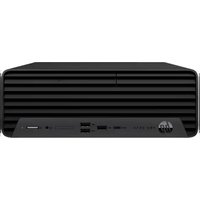
Pro SFF 400 G9 - Computer HP - Free user manual and instructions
Find the device manual for free Pro SFF 400 G9 HP in PDF.


| Product Type | Desktop Computer |
| Model | HP Pro SFF 400 G9 |
| Form Factor | Small Form Factor (SFF) |
| Dimensions (W x D x H) | Approximately 10.0 x 12.0 x 4.0 inches |
| Weight | Approximately 12.5 lbs |
| Power Supply | 200W internal power supply |
| Processor | Intel Core i3/i5/i7 (12th Gen or later) |
| Memory | Up to 64 GB DDR4 |
| Storage | SSD (up to 1 TB) or HDD (up to 2 TB) |
| Graphics | Integrated Intel UHD Graphics |
| Operating System | Windows 11 Pro |
| Ports | USB 3.2, USB-C, HDMI, DisplayPort, Ethernet, Audio |
| Wireless Connectivity | Wi-Fi 6, Bluetooth 5.2 |
| Security Features | TPM 2.0, Kensington lock slot, BIOS security |
| Maintenance | Tool-less access for HDD/SSD and RAM upgrades |
| Warranty | 1-year limited hardware warranty |
| Repairability | User-replaceable parts: memory, storage, fan |
| Environmental | Energy Star certified, EPEAT Silver |
Frequently Asked Questions - Pro SFF 400 G9 HP
User questions about Pro SFF 400 G9 HP
0 question about this device. Answer the ones you know or ask your own.
Ask a new question about this device
Download the instructions for your Computer in PDF format for free! Find your manual Pro SFF 400 G9 - HP and take your electronic device back in hand. On this page are published all the documents necessary for the use of your device. Pro SFF 400 G9 by HP.
USER MANUAL Pro SFF 400 G9 HP
Maintenance and Service Guide HP Pro SFF 400 G9 Desktop PC
SUMMARY
This guide provides maintenance information about such topics as spare parts, removal and replacement of parts, security, and backing up.
Legal information
© Copyright 2023, 2024 HP Development Company, L.P.
AMD and Radeon are trademarks of Advanced Micro Devices, Inc. Bluetooth is a trademark owned by its proprietor and used by HP Inc. under license. Intel, Core, Optane, Thunderbolt, and vPro are trademarks of Intel Corporation or its subsidiaries in the U.S. and/or other countries. Microsoft and Windows are either registered trademarks or trademarks of Microsoft Corporation in the United States and/or other countries. NVIDIA and Quadro are trademarks and/or registered trademarks of NVIDIA Corporation in the U.S. and other countries. USB Type-C and USB-C are registered trademarks of USB Implementers Forum. DisplayPort and the DisplayPort logo are trademarks owned by the Video Electronics Standards Association (VESA) in the United States and other countries. Wi-Fi is a registered trademark of Wi-Fi Alliance.
The information contained herein is subject to change without notice. The only warranties for HP products and services are set forth in the express warranty statements accompanying such products and services. Nothing herein should be construed as constituting an additional warranty. HP shall not be liable for technical or editorial errors or omissions contained herein.
Third Edition: March 2024
First Edition: May 2023
Document Part Number: N32260-003
Product notice
This guide describes features that are common to most models. Some features may not be available on your computer.
Not all features are available in all editions or versions of Windows. Systems may require upgraded and/or separately purchased hardware, drivers, software or BIOS update to take full advantage of Windows functionality. Windows is automatically updated, which is always enabled. High-speed internet and Microsoft account required. ISP fees may apply and additional requirements may apply over time for updates. See http://www.windows.com. If your product ships with Windows in S Mode: Windows in S Mode works exclusively with apps from the Microsoft Store within Windows. Certain default settings, features, and apps cannot be changed. Some accessories and apps that are compatible with Windows may not work (including some antivirus, PDF writers, driver utilities, and accessibility apps), and performance may vary, even if you switch out of S Mode. If you switch to Windows, you cannot switch back to S Mode. Learn more at Windows.com/ SmodeFAQ.
To access the latest user guides, go to http://www.hp.com/support, and follow the instructions to find your product. Then select Manuals.
Software terms
By installing, copying, downloading, or otherwise using any software product preinstalled on this computer, you agree to be bound by the terms of the HP End User License Agreement (EULA). If you do not accept these license terms, your sole remedy is to return the entire unused product (hardware and software) within 14 days for a full refund subject to the refund policy of your seller.
For any further information or to request a full refund of the price of the computer, please contact your seller.
Table of contents
1 Product features....1
Front panel components ....1
Rear panel components 2
Serial number location .... 3
2 Illustrated parts catalog....4
Computer major components....4
Mass storage devices....8
Cables 9
Miscellaneous parts 9
3 Routine care, drive guidelines, and disassembly preparation 12
Electrostatic discharge information....12
Generating static electricity 12
Preventing electrostatic damage to equipment....13
Personal grounding methods and equipment....13
Grounding the work area....14
Recommended materials and equipment....14
Operating guidelines....15
Routine care....15
General cleaning safety precautions....15
Removing dirt and debris from your computer....16
Cleaning your computer with a disinfectant....16
Cleaning the computer case....17
Cleaning the keyboard....17
Cleaning the monitor ....18
Cleaning the mouse....18
Service considerations....18
Tools and software requirements....18
Screws....19
Cables and connectors....19
Hard drives....19
Lithium coin cell battery....19
SATA hard drives....20
Cable management 20
4 Removal and replacement procedures....22
Preparation for disassembly....22
Access panel 22
Battery....23
Optical drive....25
Front bezel....26
Hard drives 27
Speaker 29
WLAN module 30
Solid-state drive....32
Memory modules (DIMMs)....34
Expansion card....37
Fan hood....39
Option board....39
Heat sink 40
Processor 42
Power supply 44
System board....45
Wireless antennas (select models only)....47
5 Troubleshooting without diagnostics....50
Before you call for technical support....50
Helpful hints 51
Solving general problems....51
Cannot access the Computer Setup (F10) Utility when booting the computer....52
Computer appears locked up and will not turn off when the power button is pressed....52
Computer will not respond to keyboard or mouse 52
Computer date and time display is incorrect 52
There is no sound or sound volume is too low....53
Cannot remove computer cover or access panel 53
Poor performance....53
System does not turn on and the lights on the front of the computer are not blinking....54
Solving power problems....54
Power supply shuts down intermittently....54
Solving hard drive problems....55
Hard drive error occurs....55
Disk drive transaction problem 55
Drive not found (identified) 55
Nonsystem disk/NTLDR missing message 56
Computer will not boot from hard drive....56
Computer seems to be locked up 56
Solving audio problems....57
Sound cuts in and out....57
Sound does not come out of the speaker or headphones 57
Computer appears to be locked up while recording audio....57
Line-in jack is not functioning properly ....57
Solving printer problems 58
Printer will not print....58
Printer will not turn on....58
Printer prints garbled information....58
Solving keyboard and mouse problems....59
Keyboard commands and typing are not recognized by the computer ....59
Mouse does not respond to movement or is too slow....59
Solving hardware installation problems....59
A new device is not recognized as part of the system....60
Computer will not start....60
Solving network problems....60
Network driver does not detect network controller....61
Network status link light never blinks....61
Diagnostics reports a failure....61
Diagnostics passes, but the computer does not communicate with the network 62
Network controller stopped working when an expansion board was added to the computer....62
Network controller stops working without apparent cause....62
Cannot connect to network server when attempting remote system installation....62
System setup utility reports unprogrammed EEPROM 62
Solving memory problems....63
System will not boot or does not function properly after installing additional memory modules....63
Out of memory error 63
Memory count during POST is wrong....63
Insufficient memory error during operation....63
Solving USB flash drive problems....64
USB flash drive is not seen as a drive letter in Windows....64
USB flash drive not found (identified) 64
System will not boot from USB flash drive 64
The computer boots to DOS after making a bootable flash drive....64
Solving internet access problems 65
Unable to connect to the internet....65
Cannot automatically launch internet programs....65
Solving software problems....65
Computer will not start up and the HP logo does not appear 66
"Illegal Operation has Occurred" error message is displayed....66
6 Computer Setup (F10) Utility 67
Using Computer Setup (F10) Utilities 67
Computer Setup Main....68
Computer Setup Security 72
Computer Setup Advanced 78
7 POST error messages....88
POST numeric codes and text messages 88
Interpreting POST diagnostic front panel lights and audible codes....95
8 Password security and resetting CMOS....98
Changing a setup or power-on password....98
Deleting a setup or power-on password 99
9 Backing up, restoring, and recovering....100
Backing up information and creating recovery media....100
Using Windows tools for backing up....100
Using the HP Cloud Recovery Download Tool to create recovery media (select products only)....100
Restoring and recovering your system....101
Creating a system restore 101
Restoring and recovery methods....101
Recovering using HP Recovery media 101
Changing the computer boot order 102
Using HP Sure Recover (select products only)....102
10 Statement of memory volatility....103
Current BIOS steps 103
Nonvolatile memory usage 105
Questions and answers....106
Using HP Sure Start (select products only)....108
11 Using HP PC Hardware Diagnostics 109
Using HP PC Hardware Diagnostics Windows (select products only)....109
Using an HP PC Hardware Diagnostics Windows hardware failure ID code....109
Accessing HP PC Hardware Diagnostics Windows....109
Accessing HP PC Hardware Diagnostics Windows from HP Support Assistant....109
Accessing HP PC Hardware Diagnostics Windows from the Start menu (select products only)......110
Downloading HP PC Hardware Diagnostics Windows....110
Downloading the latest HP PC Hardware Diagnostics Windows version from HP....110
Downloading the HP PC Hardware Diagnostics Windows from the Microsoft Store....110
Downloading HP Hardware Diagnostics Windows by product name or number (select products only) 111
Installing HP PC Hardware Diagnostics Windows....111
Using HP PC Hardware Diagnostics UEFI 111
Using an HP PC Hardware Diagnostics UEFI hardware failure ID code....111
Starting HP PC Hardware Diagnostics UEFI 111
Starting HP PC Hardware Diagnostics UEFI through HP Hotkey Support software (select products only)....112
Downloading HP PC Hardware Diagnostics UEFI to a USB flash drive.... 112
Downloading the latest HP PC Hardware Diagnostics UEFI version....113
Downloading HP PC Hardware Diagnostics UEFI by product name or number (select products only) 113
Using Remote HP PC Hardware Diagnostics UEFI settings (select products only)....113
Downloading Remote HP PC Hardware Diagnostics UEFI 113
Downloading the latest Remote HP PC Hardware Diagnostics UEFI version....113
Downloading Remote HP PC Hardware Diagnostics UEFI by product name or number....114
Customizing Remote HP PC Hardware Diagnostics UEFI settings....114
12 Power cord set requirements.... 115
General requirements 115
Japanese power cord requirements....115
Country-specific requirements....116
13 Specifications....117
Index....119
Product features1
This chapter provides you with an overview of your computer's features.
Front panel components
To identify the front panel components, use these illustrations and tables.

NOTE: Drive configuration varies by model. Some models have a bezel blank that covers one or more drive bays.
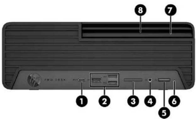
Table 1-1 Identifying the front panel components
| Front panel components | |
| (1) USB Type-C® 10 GBps port with HP Sleep andss←4 Charge | (5) Pc tton |
| (2) USB 10 GBps ports (3)ss←NOTE: Use a standard USB Type-A charging cable or cable adapter (purchased separately) when charging a small external device such as a smartphone. | (6) He e activity light |
| (3) SD reader (optional) (7) Slim optical drive (optional) | |
Table 1-1 Identifying the front panel components (continued)
| Front panel components | ||
(4) Au  | (headphone)/Audio-in (microphone) combo jack | (8) Optical drive eject button (optional) |
NOTE: The combo jack supports headphones, line output devices, microphones, line input devices, CTIA-style headsets, or OMTP-style headsets.
NOTE: Your model might have additional components available from HP.
NOTE: The light on the power button is normally white when the power is on. If the light blinks red, the computer displays a diagnostic code to indicate a problem.
Rear panel components
To identify the rear panel components, use this illustration and table.

Table 1-2 Identifying the rear panel components
| Rear panel components | ||
| 1 Security cable slot 7 DisplayPortTM monitor connector | D | |
| 2 Serial port (optional) 8 High-Definition Multimedia Interface (HDMI)IOIOI A | port (select products only) | |
| 3 Pad lock slot 9 Optional port | ||
| 4 Security screw 10 RJ-45 (network) jack | ||
| 5 Power cord connector 11 | USB port (2)** | NOTE: Use a standard USB Type-A charging cable or cable adapter (purchased separately) when charging a small external device such as a smartphone. |
Table 1-2 Identifying the rear panel components (continued)
| Rear panel components | |
| 6 Audio-out jack for powered audio devices* 12 USB 5 GBps ports (3) | NOTE: Use a standard USB Type-A charging cable or cable adapter (purchased separately) when charging a small external device such as a smartphone. |
*When you plug in a device, a menu displays enabling you to select either the Line Out or Line In option.
**From these ports, you can turn on the computer or wake it from Hibernation if you have a keyboard or mouse connected.

NOTE: Your model might have additional ports available from HP.
When a graphics card is installed in one of the system board slots, you can use the video connectors on the graphics card or the integrated graphics on the system board. The specific graphics card installed and software configuration determine the behavior.
You can disable the system board graphics by changing settings in BIOS F10 Setup.
Serial number location
Each computer has a unique serial number and a product ID number that are located on the exterior of the computer. Keep these numbers available when contacting customer service for assistance.

natural_image
Gray rectangular object with a black square at the bottom and four corner handles (no text or symbols)Illustrated parts catalog2
Use this information to determine the spare parts that are available for the computer.

NOTE: HP continually improves and changes product parts. For complete and current information about supported parts for your computer, go to https://partsurfer.hp.com/partsurfer/, select your country or region, and then follow the on-screen instructions.
Computer major components
To identify the computer major components, use this illustration and table.

Table 2-1 Computer major components and their descriptions
| Item Description Spare part number | |
| (1) Access panel | |
| For use in models with the following processors: 12000 series, G7400, G6900 N08148-001 | |
| For use in models with the following processors:13000 series, 14000 series, 300 N45387-001 | |
| (2) Power supply | |
| 240 W, 92% efficiency N05346-001 | |
| 180 W, 90% efficiency N05345-001 | |
| (3) Optical drive | |
| DVD-ROM 932497-850 | |
| DVD±RW M75172-001 | |
| Slim optical drive bezel N05308-001 | |
| Slim optical drive bezel blank N05309-001 | |
| Optical drive latch 910139-001 | |
| (4) Memory module | |
| 32 GB (DDR4-3200, NECC) | M08195-001 |
| 32 GB (DDR5-4800, NECC) | N02931-001 |
| 32 GB (DDR5-4800, NECC, NMIC) | N24667-001 |
| 32 GB (DDR5-5600) | N77572-001 |
| 16 GB (DDR4-3200, NECC) | L82038-001 |
| 16 GB (DDR4-3200, NECC, NMIC) | N03055-001 |
| 16 GB (DDR5-4800, NECC) | N02929-001 |
| 16 GB (DDR5-4800, NECC, NMIC) | N24665-001 |
| 16 GB (DDR5-5600) | N77570-001 |
| 16 GB (DDR5-5600, NMIC) | N93755-001 |
| 8 GB (DDR4-3200, NECC) | L82036-001 |
| 8 GB (DDR4-3200, NECC, NMIC) | N03053-001 |
| 8 GB (DDR5-4800, NECC) | N02930-001 |
| 8 GB (DDR5-4800, NECC, NMIC) | N24663-001 |
| 8 GB (DDR5-5600) N77571-001 | |
| 8 GB (DDR5-5600, NMIC) | N93756-001 |
| 4 GB (DDR4-3200, NECC) | L82034-001 |
(5) System board
All system boards use the following part numbers:
xxxxxx-001: Non-Windows ^® operating systems
xxxxxx-601: Windows operating system
Table 2-1 Computer major components and their descriptions (continued)
| Item Description Spare part number | |
| For use in models with a standard BIOS with the following processors: 12000 series, G7400, G6900 | M99753-001 |
| For use in models with a standard BIOS with the following processors: 12000 series, G7400, G6900 | M99753-601 |
| For use in models with a NetClone BIOS with the following processors: 12000 series, G7400, G6900 | M99754-001 |
| For use in models with a NetClone BIOS with the following processors: 12000 series, G7400, G6900 | M99754-601 |
| For use in models with a standard BIOS with the following processors: 13000 series N33532-001 | |
| For use in models with a standard BIOS with the following processors: 13000 series N33532-601 | |
| For use in models with a NetClone BIOS with the following processors: 13000 series N33533-001 | |
| For use in models with a NetClone BIOS with the following processors: 13000 series N33533-601 | |
| For use in models with a standard BIOS with the following processors: 14000 series, 300 N81935-001 | |
| For use in models with a standard BIOS with the following processors: 14000 series, 300 N81935-601 | |
| For use in models with a NetClone BIOS with the following processors: 14000 series, 300 N81936-001 | |
| For use in models with a NetClone BIOS with the following processors: 14000 series, 300 N81936-601 | |
| (6) Solid-state drive | |
| 2 TB, PCIe-4 × 4, TLC M52027-001 | |
| 1 TB, PCIe-4 × 4, TLC M16560-001 | |
| 1 TB, PCIe L85370-001 | |
| 1 TB, PCIe-4 × 4, TLC, NMIC N22908-001 | |
| 512 GB, PCIe-4 × 4, TLC M17436-001 | |
| 512 GB, PCIe-4 × 4, TLC, self-encrypting drive (SED) | M52031-001 |
| 512 GB, NMIC | N24955-001 |
| 512 GB | L85364-001 |
| 256 GB, PCIe-4 × 4, TLC, self-encrypting drive (SED) | M52029-001 |
| 256 GB, PCIe-4 × 4, NMIC | N30732-001 |
| 256 GB, PCIe-4 × 4, TLC | M52025-001 |
| 256 GB | L85354-001 |
| 128 GB, PCIe-4 × 4 | N42382-001 |
| (7) System chassis | not available as a spare part |
| (8) Processor (Include replacement thermal material): | |
| Intel® CoreTM i7-14700 (2.1 GHz, 20 core, 65 W) | N74714-003 |
| Intel Core i5-14600 (2.7 GHz, 14 core, 65 W) | N92025-003 |
| Intel Core i5-14500 (2.6 GHz, 14 core, 65 W) | N75105-003 |
Table 2-1 Computer major components and their descriptions (continued)
| Item Description Spare part number | ||
| Intel Core i5-14400 (2.5 GHz, 10 core, 65 W) N74716-003 | ||
| Intel Core i3-14100 (3.5 GHz, 4 core, 60 W) N75827-003 | ||
| Intel Core i7-13700 (2.1 GHz, 16 core, 65 W) N33971-003 | ||
| Intel Core i5-13600 (2.7 GHz, 14 core, 65 W) N35170-003 | ||
| Intel Core i5-13500 (2.5 GHz, 14 core, 65 W) N35169-003 | ||
| Intel Core i5-13400 (2.5 GHz, 10 core, 65 W) N33975-003 | ||
| Intel Core i3-13100 (3.4 GHz, 4 core, 60 W) N35171-003 | ||
| Intel Core i7-12700 (2.1 GHz, 12 core, 65 W) M98125-003 | ||
| Intel Core i5-12600 (3.3 GHz, 6 core, 65 W) N03179-003 | ||
| Intel Core i5-12500 (3.0 GHz, 6 core, 65 W) N03178-003 | ||
| Intel Core i5-12400 (2.5 GHz, 6 core, 65 W) M98123-003 | ||
| Intel Core i3-12300 (3.5 GHz, 4 core, 60 W) N03177-003 | ||
| Intel Core i3-12100 (3.3 GHz, 4 core, 60 W) N03176-003 | ||
| Intel Pentium G7400 (3.7 GHz, 2 core, 46 W) N04494-003 | ||
| Intel Celeron G6900 (3.4 GHz, 2 core, 46 W) N04493-003 | ||
| Intel 300 (3.9 GHz, 2 core, 65 W) N75826-003 | ||
| (9) | WLAN module antenna | N09898-001 |
| (10) | WLAN module | |
| Intel Wi-Fi® 6 AX201 (2 × 2) and Bluetooth® 5.2, non-vPro® | M53366-001 | |
| Intel Wi-Fi 6 AX201 (2 × 2) and Bluetooth 5.2, vPro | M53363-001 | |
| Realtek RTL8822CE Wi-Fi 5 (2 × 2) and Bluetooth 5 | M91238-001 | |
| Realtek RTL8821CE Wi-Fi 5 (1 × 1) and Bluetooth 5 | M09870-001 | |
| (11) | Speaker | N04504-001 |
| (12) | Hard drive | |
| 2 TB, 7200 rpm, 3.5 in | L89703-001 | |
| 1 TB, 7200 rpm, 3.5 in | N41735-001 | |
| 1 TB, 7200 rpm, 3.5 in, NMIC | N03048-001 | |
| (13) | Front bezel | N05306-001 |
| * | Expansion cards | |
| NVIDIA® QuadrotTM T400, 4 GB | N02795-002 | |
| NVIDIA Quadro T400, 2 GB | M48378-001 | |
| AMD® RadeonTM RX 6400, 4 GB | N13138-001 | |
| AMD Radeon RX 6300, 2 GB | N39834-001 | |
| Intel Ethernet Network Adapter I225-T1 | L89168-001 | |
Table 2-1 Computer major components and their descriptions (continued)
| Item Description Spare part number |
| Intel Ethernet Network Adapter I226-T1 N73408-001 |
| Parallel port 830632-001 |
| PS/2 + serial port L13221-001 |
| PCIe-to-RS-232 L47441-001 |
| * Option cards |
| USB Type-C M09366-001 |
| (2) USB Type-A ports M09362-001 |
| HDMI M91021-001 |
| DisplayPort M45528-001 |
| Serial port + USB N07478-001 |
| VGA port M52136-001 |
* not illustrated
Mass storage devices
To identify the mass storage devices, use this table.
Table 2-2 Mass storage devices and their descriptions
| Description Spare part number | |
| Hard drive | |
| 2 TB, 7200 rpm, 3.5 in | L89703-001 |
| 1 TB, 7200 rpm, 3.5 in, NMIC | N03048-001 |
| Optical drive | |
| DVD-ROM | 932497-850 |
| DVD±RW | M75172-001 |
| Solid-state drive | |
| 2 TB, PCIe-4 × 4, TLC | M52027-001 |
| 1 TB, PCIe-4 × 4, TLC | M16560-001 |
| 1 TB, PCIe | L85370-001 |
| 1 TB, PCIe-4 × 4, TLC, NMIC | N22908-001 |
| 1 TB, PCIe-4 × 4 | N45474-001 |
| 512 GB, PCIe-4 × 4, TLC | M17436-001 |
| 512 GB, PCIe-4 × 4, TLC, self-encrypting drive (SED) | M52031-001 |
| 512 GB, NMIC | N24955-001 |
Table 2-2 Mass storage devices and their descriptions (continued)
| Description Spare part number |
| 512 GB L85364-001 |
| 512 GB, PCIe-4 × 4 N45476-001 |
| 256 GB, PCIe-4 × 4, TLC, self-encrypting drive (SED) M52029-001 |
| 256 GB, PCIe-4 × 4, self-encrypting drive (SED) N35225-001 |
| 256 GB, PCIe-4 × 4, NMIC N30732-001 |
| 256 GB, PCIe-4 × 4, TLC M52025-001 |
| 256 GB, PCIe-4 × 4 N45477-001 |
| 256 GB L85354-001 |
| 128 GB, PCIe-4 × 4 N42382-001 |
Cables
To identify the computer cables, use this table.
Table 2-3 Cables and their descriptions
| Description Spare part number | |
| SATA power cable, 2 × 3 connector, 180 mm + 130 mm | N87191-001 |
| SATA power cable, 2 × 3 connector, 180 mm + 130 mm, RF | N87192-001 |
| SATA power cable | N05307-001 |
| SATA power cable, RF | N05310-001 |
| SATA cable, 18 cm (7 in), two straight ends, RF N20575-001 | |
| SATA cable, 18 cm (7 in), two straight ends | N20577-001 |
| SATA cable, 20 cm (8 in), two straight ends, RF | N87190-001 |
| SATA cable, 20 cm (8 in), two straight ends | N21709-001 |
| SATA cable, 34.3 cm (13.5 in), two straight ends, RF N20576-001 | |
| SATA cable, 34.3 cm (13.5 in), two straight ends | N20578-001 |
| SATA cable, 36 cm (14 in), two straight ends, RF | N87193-001 |
| SATA cable, 36 cm (14 in), two straight ends | N87194-001 |
Miscellaneous parts
To identify the various computer parts, use this table.
Table 2-4 Miscellaneous parts and their descriptions
| Description | Spare parts |
| Hood sensor | 638816-001 |
| Description Spare parts | |
| Second serial port M51207-001 | |
| Card reader N02702-001 | |
| External antenna N07482-001 | |
| External antenna, RF N93429-001 | |
| Adapter | |
| DisplayPort-to-VGA 753745-001 | |
| DisplayPort-to-DisplayPort 1.2 936297-001 | |
| Mini DisplayPort-to-HDMI 2.0 940274-001 | |
| DisplayPort-to-DisplayPort 708463-001 | |
| HDMI-to-HDMI 1.4/2.0 L05069-001 | |
| HDMI-to-HDMI 1.4/2.0, black 936296-001 | |
| USB-to-serial | 778835-001 |
| MDP-to-DVI graphics | M17386-001 |
| Mouse | |
| PS/2, optical | 674315-001 |
| USB | L95713-001 |
| HP 125 antimicrobial, wired M27883-001 | |
| HP 125 wired | M27884-001 |
| HP 128 laser, wired | M27885-001 |
| Keyboard (country codes are listed following this table) | |
| HP 655 wireless mouse + keyboard | M87234-xx1 |
| USB slim, smartcard | 911725-xx1 |
| PS/2, slim | 803821-xx1 |
| USB | L95712-xx1 |
| HP 125, wired | M27881-xx1 |
| HP 125 antimicrobial, wired M27882-xx1 | |
| Power cord (C13, 1.83 m [6 ft]) | |
| Argentina | M51846-001 |
| Australia | M51862-001 |
| Brazil | M51840-001 |
| Denmark | M51854-001 |
| Denmark (HF) | M54992-001 |
| Europe (Austria, Belgium, Finland, France, Germany, the Netherlands, Norway, and Sweden) | M51850-001 |
| Europe (HF) | M54990-001 |
| India M52019-001 | |
| Israel M51856-001 | |
| Israel (HF) M75114-001 | |
| Italy M51842-001 | |
| Japan M51864-001 | |
| Japan (12A) N49834-001 | |
| North America M51844-001 | |
| The People's Republic of China M51848-001 | |
| South Africa M51858-001 | |
| South Korea M51866-001 | |
| Switzerland M51860-001 | |
| Switzerland (HF) | M54994-001 |
| Taiwan | M51870-001 |
| Thailand | M51868-001 |
| The United Kingdom | M51852-001 |
| The United Kingdom (HF) | M75112-001 |
Table 2-5 Spare part country codes
| For use in country or region | Spare part number | For use in country or region | Spare part number | For use in country or region | Spare part number |
| Belgium | -181 | Hungary | -211 | Russia | -251 |
| BHCSY (Bosnia/ Herzegovina/Croatia/ Slovenia/Yugoslavia) | -B41 | India | -D61 | Saudi Arabia | -171 |
| Brazil | -201 | International | -L31 | South Korea | -KD1 |
| Bulgaria | -261 | Israel | -BB1 | Spain | -071 |
| Chile | -161 | Italy | -061 | Sweden | -101 |
| Czech/Slovakia | -CG1 | Japan | -291 | Switzerland | -111 |
| Denmark | -081 | Kazakhstan | -DF1 | Thailand | -281 |
| France | -051 | Netherlands | -DX1 | Turkey | -141 |
| French Arabic | -DE1 | Norway | -091 | Ukraine | -BD1 |
| French Canada | -121 | Portugal | -131 | United Kingdom | -031 |
| Germany | -041 | Romania | -271 | United States | -001 |
| Greece | -151 |
3 Routine care, drive guidelines, and disassembly preparation
This information provides general service information for the computer. Adherence to the procedures and precautions is essential for proper service.

IMPORTANT: When the computer is plugged into an AC power source, DC voltage is always applied to the system board. You must disconnect the power cord from the power source before opening the computer to prevent electric shock, system board, or component damage.
Electrostatic discharge information
A sudden discharge of static electricity from your finger or other conductor can destroy static-sensitive devices or microcircuitry. Often the spark is neither felt nor heard, but damage occurs.
An electronic device exposed to electrostatic discharge (ESD) might not appear to be affected at all and can work perfectly throughout a normal cycle. The device might function normally for a while, but it has been degraded in the internal layers, reducing its life expectancy.
Networks built into many integrated circuits provide some protection, but in many cases, the discharge contains enough power to alter device parameters or melt silicon junctions.

IMPORTANT: To prevent damage to the device when you are removing or installing internal components, observe these precautions:
- Keep components in their electrostatic-safe containers until you are ready to install them.
- Before touching an electronic component, discharge static electricity by using the guidelines described in this section.
- Avoid touching pins, leads, and circuitry. Handle electronic components as little as possible.
- If you remove a component, place it in an electrostatic-safe container.
Generating static electricity
This table shows how humidity affects the electrostatic voltage levels generated by different activities. A product can be degraded by 700 V of static electricity.
- Different activities generate different amounts of static electricity.
• Static electricity increases as humidity decreases.
Table 3-1 Static electricity occurrence based on activity and humidity
| Relative humidity | |||
| Event 55% 40% 10% | |||
| Walking across carpet | 7,500 V | 15,000 V | 35,000 V |
| Walking across vinyl floor | 3,000 V | 5,000 V | 12,000 V |
| Motions of bench worker | 400 V | 800 V | 6,000 V |
| Removing DIPs (dual in-line packages) from plastic tube | 400 V | 700 V | 2,000 V |
| Removing DIPs from vinyl tray | 2,000 V | 4,000 V | 11,500 V |
| Removing DIPs from polystyrene foam | 3,500 V | 5,000 V | 14,500 V |
| Removing bubble pack from PCB (printed circuit board) | 7,000 V | 20,000 V | 26,500 V |
| Packing PCBs in foam-lined box | 5,000 V | 11,000 V | 21,000 V |
Multiple electric components can be packaged in plastic tubes, trays, or polystyrene foam.
Preventing electrostatic damage to equipment
Many electronic components are sensitive to ESD. Circuitry design and structure determine the degree of sensitivity. The following packaging and grounding precautions are necessary to prevent static electricity damage to electronic components.
• To avoid hand contact, transport products in static-safe containers such as tubes, bags, or boxes.
- Protect all electrostatic parts and assemblies with conductive or approved containers or packaging.
- Keep electrostatic-sensitive parts in their containers until they arrive at static-free stations.
- Place items on a grounded surface before removing them from their container.
- Always be properly grounded when touching a sensitive component or assembly.
- Avoid contact with pins, leads, or circuitry.
- Place reusable electrostatic-sensitive parts from assemblies in protective packaging or conductive foam.
Personal grounding methods and equipment
Use this equipment to prevent static electricity damage to electronic components.
- Wrist straps are flexible straps with a maximum of 1M ± 10% resistance in the ground cords. To provide proper ground, a strap must be worn snug against bare skin. The ground cord must be connected and fit snugly into the banana plug connector on the grounding mat or workstation.
- Heel straps/Toe straps/Boot straps can be used at standing workstations and are compatible with most types of shoes or boots. On conductive floors or dissipative floor mats, use them on both feet with a maximum of 1 MΩ ±10% resistance between the operator and ground.
Table 3-2 Static shielding protection levels
| Static shielding protection levels | |
| Method Voltage | |
| Antistatic plastic | 1,500 V |
| Carbon-loaded plastic | 7,500 V |
| Metallized laminate | 15,000 V |
Grounding the work area
To prevent static damage at the work area, use these precautions.
- Cover the work surface with approved static-dissipative material. Provide a wrist strap connected to the work surface and properly grounded tools and equipment.
- Use static-dissipative mats, foot straps, or air ionizers to give added protection.
- Handle electrostatic sensitive components, parts, and assemblies by the case or PCB laminate. Handle them only at static-free work areas.
- Turn off power and input signals before inserting and removing connectors or test equipment.
- Use fixtures made of static-safe materials when fixtures must directly contact dissipative surfaces.
- Keep work area free of nonconductive materials such as ordinary plastic assembly aids and polystyrene foam.
- Use field service tools, such as cutters, screwdrivers, and vacuums, that are conductive.
Recommended materials and equipment
HP recommends these materials and equipment to prevent static electricity.
- Antistatic tape
- Antistatic smocks, aprons, or sleeve protectors
- Conductive bins and other assembly or soldering aids
- Conductive foam
- Conductive tabletop workstations with ground cord of 1M ± 10% resistance
- Static-dissipative table or floor mats with hard tie to ground
- Field service kits
• Static awareness labels - Wrist straps and footwear straps providing 1 MΩ ±10% resistance
• Material handling packages
• Conductive plastic bags
• Conductive plastic tubes
• Conductive tote boxes
- Opaque shielding bags
• Transparent metallized shielding bags
•Transparent shielding tubes
Operating guidelines
This information details how to prevent overheating and to help prolong the life of the computer.
- Keep the computer away from excessive moisture, direct sunlight, and extremes of heat and cold.
- Operate the computer on a sturdy, level surface. Leave a 10.2 cm (4 inch) clearance on all vented sides of the computer and above the monitor to permit the required airflow.
- Never restrict the airflow into the computer by blocking any vents or air intakes. Do not place the keyboard, with the keyboard feet down, directly against the front of the desktop unit as this also restricts airflow.
- Occasionally clean the air vents on all vented sides of the computer. Lint, dust, and other foreign matter can block the vents and limit the airflow. Be sure to unplug the computer before cleaning the air vents.
- Never operate the computer with the cover or side panel removed.
- Do not stack computers on top of each other or place computers so near each other that they are subject to each other's recirculated or preheated air.
- If the computer is to be operated within a separate enclosure, intake and exhaust ventilation must be provided on the enclosure, and the same operating guidelines listed previously still apply.
- Keep liquids away from the computer and keyboard.
- Never cover the ventilation slots on the monitor with any type of material.
• Install or enable power management functions of the operating system or other software, including Sleep states.
Routine care
Use this information to properly care for your computer.
General cleaning safety precautions
Use this information to safely clean your computer.
CAUTION: To prevent electric shock or damage to components, never clean a product while it is turned on or plugged in.
- Never use solvents or flammable solutions to clean the computer.
-
Never immerse any parts in water or cleaning solutions; apply any liquids to a clean cloth and then use the cloth on the component.
• Always unplug the computer when cleaning with liquids or damp cloths. -
Always unplug the computer before cleaning the keyboard, mouse, or air vents.
- Disconnect the keyboard before cleaning it.
- Wear safety glasses equipped with side shields when cleaning the keyboard.
Removing dirt and debris from your computer
Here are the recommended steps to clean dirt and debris from your computer.
- Wear disposable gloves made of latex (or nitrile gloves, if you are latex-sensitive) when cleaning the surfaces.
-
Turn off your device and unplug the power cord and other connected external devices. Remove any installed batteries from items such as wireless keyboards.
CAUTION: To prevent electric shock or damage to components, never clean a product while it is turned on or plugged in. -
Moisten a microfiber cloth with water. The cloth should be moist, but not dripping wet.
IMPORTANT: To avoid damaging the surface, avoid abrasive cloths, towels, and paper towels.
- Wipe the exterior of the product gently with the moistened cloth.
IMPORTANT: Keep liquids away from the product. Avoid getting moisture in any openings. If liquid makes its way inside your HP product, it can cause damage to the product. Do not spray liquids directly on the product. Do not use aerosol sprays, solvents, abrasives, or cleaners containing hydrogen peroxide or bleach that might damage the finish.
-
Start with the display (if applicable). Wipe carefully in one direction, and move from the top of the display to the bottom. Finish with any flexible cables, like power cord, keyboard cable, and USB cables.
-
Be sure that surfaces have completely air-dried before turning the device on after cleaning.
-
Discard the gloves after each cleaning. Clean your hands immediately after you remove the gloves.
See Cleaning your computer with a disinfectant on page 16 for recommended steps to clean the high-touch, external surfaces on your computer to help prevent the spread of harmful bacteria and viruses.
Cleaning your computer with a disinfectant
The World Health Organization (WHO) recommends cleaning surfaces, followed by disinfection, as a best practice for preventing the spread of viral respiratory illnesses and harmful bacteria.
After cleaning the external surfaces of your computer using the steps in Removing dirt and debris from your computer on page 16, you might also choose to clean the surfaces with a disinfectant. A disinfectant that is within HP's cleaning guidelines is an alcohol solution consisting of 70% isopropyl alcohol and 30% water. This solution is also known as rubbing alcohol and is sold in most stores.
Follow these steps when disinfecting high-touch, external surfaces on your computer:
-
Wear disposable gloves made of latex (or nitrile gloves, if you are latex-sensitive) when cleaning the surfaces.
-
Turn off your device and unplug the power cord and other connected external devices. Remove any installed batteries from items such as wireless keyboards.
CAUTION: To prevent electric shock or damage to components, never clean a product while it is turned on or plugged in.
- Moisten a microfiber cloth with a mixture of 70% isopropyl alcohol and 30% water. The cloth should be moist, but not dripping wet.
CAUTION: Do not use any of the following chemicals or any solutions that contain them, including spray-based surface cleaners: bleach, peroxides (including hydrogen peroxide), acetone, ammonia, ethyl alcohol, methylene chloride, or any petroleum-based materials, such as gasoline, paint thinner, benzene, or toluene.
IMPORTANT: To avoid damaging the surface, avoid abrasive cloths, towels, and paper towels.
- Wipe the exterior of the product gently with the moistened cloth.
IMPORTANT: Keep liquids away from the product. Avoid getting moisture in any openings. If liquid makes its way inside your HP product, it can cause damage to the product. Do not spray liquids directly on the product. Do not use aerosol sprays, solvents, abrasives, or cleaners containing hydrogen peroxide or bleach that might damage the finish.
-
Start with the display (if applicable). Wipe carefully in one direction, and move from the top of the display to the bottom. Finish with any flexible cables, like power cord, keyboard cable, and USB cables.
-
Be sure that surfaces have completely air-dried before turning the device on after cleaning.
-
Discard the gloves after each cleaning. Clean your hands immediately after you remove the gloves.
Cleaning the computer case
Follow all safety precautions before cleaning the computer case.
To clean the computer case, follow these procedures:

NOTE: You can also use these procedures to clean the tops of the keys, keyboard body, monitor body, or mouse body.
- To remove light stains or dirt, use plain water with a clean, lint-free cloth or swab.
- For stronger stains, use a mild dishwashing liquid diluted with water. Rinse well by wiping it with a cloth or swab dampened with clear water.
- For stubborn stains, use isopropyl (rubbing) alcohol. No rinsing is needed because the alcohol evaporates quickly and does not leave a residue.
- After cleaning, always wipe the unit with a clean, lint-free cloth.
- Occasionally clean the air vents on the computer. Lint and other foreign matter can block the vents and limit the airflow.
Cleaning the keyboard
Use this information to properly clean the keyboard. Follow all safety precautions before cleaning the keyboard.
To clean the tops of the keys or the keyboard body, follow the procedures described in Cleaning the computer case on page 17.
When cleaning debris from under the keys, review all rules in General cleaning safety precautions on page 15 before following these procedures.
CAUTION: Use safety glasses equipped with side shields before attempting to clean debris from under the keys.
- You can remove visible debris underneath or between the keys by vacuuming or shaking.
- You can use canned, pressurized air to clean debris from under the keys. Use caution because too much air pressure can dislodge lubricants applied under the wide keys.
- If you remove a key, use a specially designed key puller to prevent damage to the keys. This tool is available through many electronic supply outlets.
IMPORTANT: Never remove a wide leveled key (such as the space bar) from the keyboard. If these keys are improperly removed or installed, the keyboard might not function properly.
- You can clean under a key with a swab moistened with isopropyl alcohol and squeezed out. Be careful not to wipe away lubricants necessary for proper key functions. Use tweezers to remove any fibers or dirt in confined areas. Allow the parts to air dry before reassembly.
Cleaning the monitor
Follow all safety precautions before cleaning dirt and debris from your computer. Use this information to properly clean the monitor.
- Wipe the monitor screen with a clean cloth moistened with water or with a towelette designed for cleaning monitors. Do not use sprays or aerosols directly on the screen; the liquid can seep into the housing and damage a component. Never use solvents or flammable liquids on the monitor.
- To clean the monitor body, follow the procedures in Cleaning the computer case on page 17.
Cleaning the mouse
Follow all safety precautions before cleaning your mouse. Use this information to properly clean the mouse.
To clean the mouse body, follow the procedures in Cleaning the computer case on page 17.
Service considerations
Keep these considerations in mind during the disassembly and assembly of the computer.
Tools and software requirements
Servicing the computer requires these tools.
- Torx T-15 screwdriver
- Flat-bladed screwdriver (can sometimes be used in place of the Torx screwdriver)
•Phillips P1 screwdriver
• Nonconductive, nonmarking pry tool
• Diagnostics software
Screws
The screws used in the computer are not interchangeable. They could have standard or metric threads and might be of different lengths.
If you use an incorrect screw during the reassembly process, it can damage the unit. HP strongly recommends that you keep all screws that you remove during disassembly with the removed part and then return them to their proper locations.

IMPORTANT: As you remove each subassembly from the computer, place it away from the work area to prevent damage.
Cables and connectors
Use this information to properly handle cables.
Apply only the tension required to seat or unseat the cables during insertion or removal from the connector. Handle cables by the connector whenever possible. In all cases, avoid bending or twisting the cables, and route the cables so that they cannot be caught or snagged by parts being removed or replaced.

IMPORTANT: When servicing this computer, be sure to place cables in their proper location during the reassembly process. Improper cable placement can damage the computer.
Hard drives
Handle hard drives as delicate, precision components, and avoid all physical shock and vibration. This advice applies to failed drives as well as replacement spares.
- If a drive must be mailed, place the drive in a bubble-pack mailer or other suitable protective packaging and label the package "Fragile: Handle With Care."
- Do not remove hard drives from the shipping package for storage. Keep hard drives in their protective packaging until they are actually mounted in the computer.
- Avoid dropping drives from any height onto any surface.
- If you are inserting or removing a hard drive, turn off the computer. Do not remove a hard drive while the computer is on or in standby mode.
- Before handling a drive, ensure that you are discharged of static electricity. While handling a drive, avoid touching the connector.
- Do not use excessive force when inserting a drive.
- Avoid exposing a hard drive to liquids, temperature extremes, or products that have magnetic fields such as monitors or speakers.
Lithium coin cell battery
The battery that comes with the computer provides power to the real-time clock and has a minimum lifetime of approximately three years.
See the removal and replacement chapter for replacement instructions.
WARNING! This computer contains a lithium battery. There is a risk of fire and chemical burn if the battery is handled improperly. Do not disassemble, crush, puncture, short external contacts, dispose of in water or fire, or expose it to temperatures higher than 140^ F ( 60^ C). Do not attempt to recharge the battery.
NOTE: Do not dispose of batteries, battery packs, and accumulators with general household waste. To forward them to recycling centers or proper disposal, use the public collection system or return them to HP, their authorized partners, or their agents.
SATA hard drives
The Self Monitoring Analysis and Recording Technology (SMART) ATA drives for the HP Personal Computers have built-in drive failure prediction that warns the user or network administrator of an impending failure or crash of the hard drive.
The SMART drive tracks fault prediction and failure indication parameters such as reallocated sector count, spin retry count, and calibration retry count. If the drive determines that a failure is imminent, it generates a fault alert.
Table 3-3 SATA hard drive characteristics
| Serial ATA hard drive characteristics |
| Number of pins/conductors in data cable 7/7 |
| Number of pins in power cable 15 |
| Maximum data cable length 100 cm (39.37 in) |
| Data interface voltage differential 400 mV–700 mV |
| Drive voltages 3.3 V, 5 V, 12 V |
| Jumpers for configuring drive N/A |
| Data transfer rate 6.0 Gbps |
Always use an HP-approved SATA 6.0 Gbps cable because it is fully backwards compatible with the SATA 1.5 Gbps drives. Current HP desktop products ship with SATA 6.0 Gbps hard drives.
SATA data cables are susceptible to damage if overflexed. Never crease a SATA data cable and never bend it tighter than a 30 mm (1.18 in) radius.
The SATA data cable is a thin, seven-pin cable designed to transmit data for only a single drive.
Cable management
Always follow good cable management practices when working inside the computer.
- Keep cables away from major heat sources like the heat sink.
- Keep cables clear of sliding or moveable parts to prevent them from being cut or crimped when the parts are moved.
-
When folding a flat ribbon cable, never fold to a sharp crease. Sharp creases can damage the wires.
-
Do not bend any cable sharply. A sharp bend can break the internal wires.
- Never bend a SATA data cable tighter than a 30 mm (1.18 in) radius.
- Never crease a SATA data cable.
Removal and replacement procedures4
Adherence to these procedures and precautions is essential for proper service. After completing all necessary removal and replacement procedures, run the Diagnostics utility to verify that all components operate properly.

NOTE: Not all features listed in this guide are available on all computers.

NOTE: HP continually improves and changes product parts. For complete and current information about supported parts for your computer, go to https://partsurfer.hp.com/partsurfer/, select your country or region, and then follow the on-screen instructions.
Preparation for disassembly
Use this information to properly prepare to disassemble and reassemble the computer.
See Routine care, drive guidelines, and disassembly preparation on page 12 for initial safety procedures.
- Turn off the computer. If you are unsure whether the computer is off or in Hibernation, turn the computer on, and then shut it down through the operating system.

IMPORTANT: Turn off the computer before disconnecting any cables.
Regardless of the power state, voltage is always present on the system board as long as the system is plugged into an active AC outlet. In some systems, the cooling fan is on even when the computer is in the Standby or Suspend modes. Always disconnect the power cord before servicing a unit.
After you plug in the AC power cord, wait five seconds before you press the power button.
- Disconnect the power from the computer by unplugging the power cord from the computer.
- Disconnect all external devices from the computer
- (Select products only) If the computer is on a stand, remove the computer from the stand.

CAUTION: Beware of sharp edges inside the chassis.

NOTE: During disassembly, label each cable as you remove it, and note its position and routing. Keep all screws with the removed components.
Access panel
To remove the access panel, use these procedures.
Before removing the access panel, follow these steps:
Table 4-1 Access panel descriptions and part numbers
| Description Spare part number |
| For use in models with the following processors: 12000 series, G7400, G6900 N08148-001 |
| For use in models with the following processors:13000 series, 14000 series, 300 N45387-001 |
Prepare the computer for disassembly (see Preparation for disassembly on page 22).
Remove the access panel:
- Loosen the thumbscrew (1) on the rear of the computer.
- Use the tab (2) to slide the access panel backward (3) and lift it off the computer.

To install the access panel, reverse the removal procedure.
Battery
To remove the battery, use these procedures. The battery that comes with the computer provides power to the real-time clock. When replacing the battery, use a battery equivalent to the battery originally installed in the computer. The computer comes with a 3 V lithium coin cell battery.
WARNING! The computer contains an internal lithium manganese dioxide battery. There is a risk of fire and burns if the battery is not handled properly. To reduce the risk of personal injury:
- Do not attempt to recharge the battery.
- Do not expose to temperatures higher than 60^ (149°F).
- Do not disassemble, crush, puncture, short external contacts, or dispose of in fire or water.
- Replace the battery only with the HP spare part that is designated for this product.
▲WARNING
• INGESTION HAZARD: This product contains a button cell or coin battery.
• DEATH or serious injury can occur if ingested.
• A swallowed button cell or coin battery can cause Internal Chemical Burns in as little as 2 hours.
- KEEP new and used batteries OUT OF REACH of CHILDREN
- Seek immediate medical attention if a battery is suspected to be swallowed or inserted inside any part of the body.


IMPORTANT: Before replacing the battery, back up the computer CMOS settings. When the battery is removed or replaced, the CMOS settings are cleared.
Static electricity can damage the electronic components of the computer or optional equipment. Before beginning these procedures, be sure that you are discharged of static electricity by briefly touching a grounded metal object.

NOTE: You can extend the lifetime of the lithium battery by plugging the computer into an AC outlet. The lithium battery is used only when the computer is not connected to AC power.
HP encourages customers to recycle used electronic hardware, HP original print cartridges, and rechargeable batteries. For more information about recycling programs, go to http://www.hp.com/recycle.
Before removing the battery, follow these steps:
-
Prepare the computer for disassembly (see Preparation for disassembly on page 22).
-
Remove the access panel (see Access panel on page 22).
Remove the battery:
- Squeeze the latch (1), and then lift the cover (2) to open it.

- To release the battery from its holder, squeeze the metal clamp (1) that extends above one edge of the battery. When the battery (2) pops up, lift it out.

natural_image
Three views of a battery pack with labeled components (1, 2), showing internal compartments and mounting features (no text or symbols beyond labels)- With the positive side up, insert the battery (1) onto the battery socket at an angle, and then press the battery (2) down until it locks into place. The battery holder automatically secures the battery in the proper position.

natural_image
Two 3D diagrams of a device component with labeled parts, showing internal structures and mounting features (no text or symbols present)- Insert the cover (1) onto the battery socket at an angle, and then press the cover (2) down until it locks into place.

natural_image
Mechanical assembly diagram showing two components with arrows indicating motion (no text or symbols)Optical drive
To remove the optical drive, use these procedures.
Table 4-2 Optical drive descriptions and part numbers
| Description Spare part number |
| DVD-ROM 932497-850 |
| DVD±RW M75172-001 |
| Slim optical drive bezel N05308-001 |
| Slim optical drive bezel blank N05309-001 |
| Optical drive latch 910139-001 |
Before removing the optical drive, follow these steps:
- Prepare the computer for disassembly (see Preparation for disassembly on page 22).
- Remove the access panel (see Access panel on page 22).
Remove the optical drive:
- Disconnect the power cable (1) and data cable (2) from the rear of the optical drive.
- Push the green release latch (3) on the left rear side of the optical drive toward the center of the drive, and then slide the drive (4) forward and out of the bay.
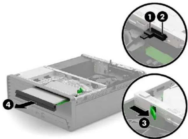
To install the optical drive, reverse the removal procedure.
Front bezel
To remove the front bezel, use these procedures.
Table 4-3 Front bezel description and part number
| Description Spare part number |
| Front bezel N05306-001 |
Before removing the front bezel, follow these steps:
- Prepare the computer for disassembly (see Preparation for disassembly on page 22).
- Remove the access panel (see Access panel on page 22).
- Remove the optical drive (see Optical drive on page 25).
Remove the front bezel:
- Position the computer with the front toward you.
- Disengage the tabs (1) on the top of the front bezel from the slots in the system chassis.
- Swing the front bezel (2) down and away from the system chassis.

natural_image
Interior view of a computer case with labeled components (1 and 2), showing internal structure without any text or symbols.- Remove the front bezel.
To install the front bezel, reverse the removal procedure.
Hard drives
To remove the hard drives, use these procedures. The hard drives are located inside the front chassis.
Table 4-4 Hard drive descriptions and part numbers
| Description Spare part number |
| 2 TB, 7200 rpm, 3.5 in L89703-001 |
| 1 TB, 7200 rpm, 3.5 in, NMIC N03048-001 |
| 1 TB, 7200 rpm, 3.5 in N41735-001 |
Before removing the hard drives, follow these steps:
- Prepare the computer for disassembly (see Preparation for disassembly on page 22).
- Remove the access panel (see Access panel on page 22).
- Remove the optical drive (see Optical drive on page 25).
- Remove the front bezel (see Front bezel on page 26).
Remove the hard drives:
- Use the leverage point (1) to swing the front chassis (2) up and toward the front of the computer.
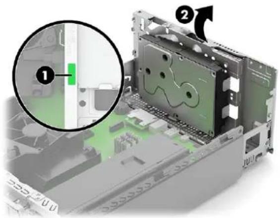
natural_image
3D rendering of a computer chassis with an inset magnified view showing internal components (no text or symbols visible)- Disconnect the hard drive power cable (1) from the hard drive.
- Disconnect the hard drive data cable (2) from the hard drive.
- Remove the three Torx15 screws (3) that secure the hard drive to the drive cage.
- Remove the hard drive (4) from the drive cage.

- Release the drive power cable from the retention clip (1) that is built into the main chassis.
- Release the drive data cable from the retention clip (2) that is built into the main chassis.
-
Disconnect the drive power cable (3) from the system board.
-
Disconnect the drive data cable (4) from the system board.
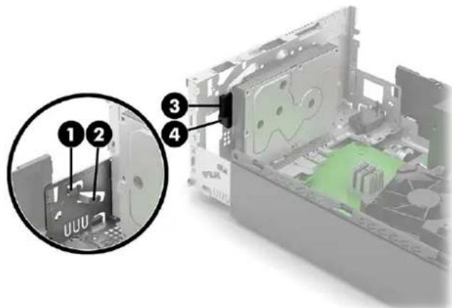
- Remove the hard drive drive cables from the computer.
To install the hard drive and hard drive cables, reverse the removal procedure.
Speaker
To remove the speaker, use these procedures. A single speaker is located on the left side of the computer behind the front bezel, inside the chassis.
Table 4-5 Speaker description and part number
| Description Spare part number |
| Speaker N04504-001 |
Before removing the speaker, follow these steps:
- Prepare the computer for disassembly (see Preparation for disassembly on page 22).
- Remove the access panel (see Access panel on page 22).
- Remove the optical drive (see Optical drive on page 25).
- Remove the front bezel (see Front bezel on page 26).
Remove the speaker:
- Disconnect the speaker cable (1) from the system board.
-
Release the speaker cable from the retention clip (2) that is built into the system chassis.
-
Release the speaker clips from the rubber retention posts (3) that are built into the system chassis.

- Remove the speaker and cable.
To install the speaker, reverse the removal procedures.
WLAN module
To remove the WLAN module, use these procedures.
Table 4-6 WLAN module descriptions and part numbers
| Description Spare part number |
| Intel Wi-Fi 6 AX201 (2 × 2) and Bluetooth 5.2, non-vPro M53366-001 |
| Intel Wi-Fi 6 AX201 (2 × 2) and Bluetooth 5.2, vPro M53363-001 |
| Realtek RTL8822CE Wi-Fi 5 (2 × 2) and Bluetooth 5 M91238-001 |
| Realtek RTL8821CE Wi-Fi 5 (1 × 1) and Bluetooth 5 M09870-001 |
| WLAN antenna cover L38183-001 |
The WLAN module is located near the memory modules.

NOTE: WLAN module appearance can vary.
Before removing the WLAN module, follow these steps:
-
Prepare the computer for disassembly (see Preparation for disassembly on page 22).
-
Remove the access panel (see Access panel on page 22).
-
Remove the optical drive (see Optical drive on page 25).
-
Remove the front bezel (see Front bezel on page 26).
Remove the WLAN module:
-
Remove the Phillips screw (1) that secures the module and the WLAN module bracket to the computer.
-
Remove the WLAN module bracket (2).
-
Disconnect the antenna cables from the module (3).

NOTE: The WLAN antenna cable labeled 1/MAIN connects to the WLAN module Main terminal. The WLAN antenna cable labeled 2/AUX connects to the WLAN module Aux terminal.
-
Lift the front edge of the WLAN module (4) until it rests at an angle.
-
Pull the module to remove it from the socket (5).

- If the WLAN antenna is not connected to the terminal on the WLAN module, a protective sleeve must be installed on the antenna connector, as shown in the following illustration.

natural_image
Diagram of a cable with a connector and arrow indicating direction (no text or symbols)To install the WLAN module, reverse the removal procedure.

NOTE: WLAN modules are designed with a notch to prevent incorrect insertion.
Solid-state drive
To remove the solid-state drive, use these procedures. The system board offers two solid-state drive slots.
Table 4-7 Solid-state drive descriptions and part numbers
| Description Spare part number | |
| 2 TB, PCIe-4 × 4, TLC M52027-001 | |
| 1 TB, PCIe-4 × 4, TLC M16560-001 | |
| 1 TB, PCIe L85370-001 | |
| 1 TB, PCIe-4 × 4, TLC, NMIC N22908-001 | |
| 512 GB, PCIe-4 × 4, TLC M17436-001 | |
| 512 GB, PCIe-4 × 4, TLC, self-encrypting drive (SED) M52031-001 | |
| 512 GB, NMIC N24955-001 | |
| 512 GB L85364-001 | |
| 256 GB, PCIe-4 × 4, TLC, self-encrypting drive (SED) M52029-001 | |
| 256 GB, PCIe-4 × 4, NMIC N30732-001 | |
| 256 GB, PCIe-4 × 4, TLC | M52025-001 |
| 256 GB | L85354-001 |
| 128 GB, PCIe-4 × 4 | N42382-001 |
| Solid-state drive heat sink | N02705-001 |
Before removing the solid-state drive, follow these steps:
- Prepare the computer for disassembly (see Preparation for disassembly on page 22).
- Remove the access panel (see Access panel on page 22).
Remove the solid-state drive:
- Locate the solid-state drive on the system board:

natural_image
Top-down view of a green printed circuit board with visible components and connectors (no text or symbols)- Remove the screw that secures the drive.

NOTE: System board appearance might vary.

natural_image
3D diagram of an electronic component with a highlighted internal structure and an arrow indicating assembly or movement (no text or symbols present)- Lift the drive up (1), and then pull the drive out of the system board connector (2).

natural_image
3D diagram of an electric vehicle chassis with labeled components (no text or symbols present)To install the solid-state drive, reverse the removal procedure.
Memory modules (DIMMs)
To remove the memory modules, use this information and procedures.
Table 4-8 Memory module descriptions and part numbers
| Description Spare part number | |
| 32 GB (DDR4-3200, NECC) M08195-001 | |
| 32 GB (DDR5-4800, NECC) N02931-001 | |
| 32 GB (DDR5-4800, NECC, NMIC) N24667-001 | |
| 32 GB (DDR5-5600) N77572-001 | |
| 16 GB (DDR4-3200, NECC) L82038-001 | |
| 16 GB (DDR4-3200, NECC, NMIC) N03055-001 | |
| 16 GB (DDR5-4800, NECC) N02929-001 | |
| 16 GB (DDR5-4800, NECC, NMIC) N24665-001 | |
| 16 GB (DDR5-5600) N77570-001 | |
| 16 GB (DDR5-5600, NMIC) N93755-001 | |
| 8 GB (DDR4-3200, NECC) | L82036-001 |
| 8 GB (DDR4-3200, NECC, NMIC) | N03053-001 |
| 8 GB (DDR5-4800, NECC) | N02930-001 |
| 8 GB (DDR5-4800, NECC, NMIC) | N24663-001 |
| 8 GB (DDR5-5600) | N77571-001 |
| 8 GB (DDR5-5600, NMIC) | N93756-001 |
| 4 GB (DDR4-3200, NECC) | L82034-001 |
The memory sockets on the system board are populated with at least one preinstalled memory module. To achieve the maximum memory support, you can populate the system board with up to 128 GB of memory configured in a high-performing dual-channel mode.
The computer supports the following setups:
- 512 Mbit, 1 Gbit, 2 Gbit, and 4 Gbit non-ECC memory technologies
- Single-sided and double-sided memory modules
- Memory modules constructed with ×8 and ×16 DDR devices; memory modules constructed with ×4 SDRAM are not supported

NOTE: The system does not operate properly if you install unsupported memory modules.
Four memory sockets are located on the system board, with two sockets per channel. The sockets are labeled DIMM1, DIMM2, DIMM3, and DIMM4. Sockets DIMM1 and DIMM2 operate in memory channel B. Sockets DIMM3 and DIMM4 operate in memory channel A.
The system automatically operates in single-channel mode, dual-channel mode, or flex mode, depending on how the DIMMs are installed.

NOTE: Single-channel and unbalanced dual-channel memory configurations result in inferior graphics performance.
- The system operates in single-channel mode if the DIMM sockets are populated in one channel only.
- The system operates in a higher-performing dual-channel mode if the total memory capacity of the DIMMs in channel A is equal to the total memory capacity of the DIMMs in channel B. The technology and device width can vary between the channels. For example, if channel A is populated with two 1 GB DIMMs and channel B is populated with one 2 GB DIMM, the system operates in dual-channel mode.
- The system operates in flex mode if the total memory capacity of the DIMMs in channel A is not equal to the total memory capacity of the DIMMs in channel B. In flex mode, the channel populated with the least amount of memory describes the total amount of memory assigned to dual channel, and the remainder is assigned to single channel. For optimal speed, balance the channels so that the largest amount of memory is spread between the two channels. If one channel has more memory than the other, assign the larger amount to channel A. For example, if you are populating the sockets with one 2 GB DIMM and three 1 GB DIMMs, populate channel A with the 2 GB DIMM and one 1 GB DIMM, and populate channel B channel with the other two 1 GB DIMMs. With this configuration, 4 GB runs as dual channel and 1 GB runs as single channel.
- In any mode, the maximum operational speed is determined by the slowest DIMM in the system.

IMPORTANT: You must disconnect the power cord and wait approximately 30 seconds for the power to drain before adding or removing memory modules. Regardless of the power state, voltage is always supplied to the memory modules as long as the computer is plugged into an active AC outlet. Adding or removing memory modules while voltage is present can cause irreparable damage to the memory modules or system board.
The memory module sockets have gold-plated metal contacts. When upgrading the memory, it is important to use memory modules with gold-plated metal contacts to prevent corrosion, oxidation, or both resulting from having incompatible metals in contact with each other.
Static electricity can damage the electronic components of the computer or optional cards. Before beginning these procedures, be sure that you are discharged of static electricity by briefly touching a grounded metal object. For more information, see Electrostatic discharge information on page 12.
When handling a memory module, be careful not to touch any of the contacts. Doing so can damage the module.
Before replacing the memory modules, follow these steps:
- Prepare the computer for disassembly (see Preparation for disassembly on page 22).
- Remove the access panel (see Access panel on page 22).
- Remove the optical drive (see Optical drive on page 25).
- Remove the front bezel (see Front bezel on page 26).
Replace a memory module:
- To remove a memory module, open both latches of the memory module socket (1), and then remove the memory module from the socket (2).
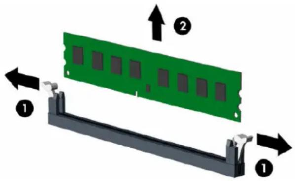
- To install a memory module, open both latches of the memory module socket (1), and insert the memory module into the socket (2). Press the module down into the socket so that the module is fully inserted and properly seated. Be sure that the latches are in the closed position (3).


NOTE: You can install a memory module in only one way. Match the notch on the module with the tab on the memory socket.
Populate the black DIMM sockets before the white DIMM sockets.
For maximum performance, populate the sockets so that the memory capacity is spread as equally as possible between channel A and channel B.
The computer automatically recognizes the additional memory when you turn on the computer.
Expansion card
The computer has one PCI Express ×1 expansion socket, two PCI Express ×16 expansion sockets, and one PCI Express ×8 expansion socket.
Table 4-9 Expansion card descriptions and part numbers
| Description Spare part number |
| NVIDIA Quadro T400, 4 GB N02795-002 |
| NVIDIA Quadro T400, 2 GB M48378-001 |
| AMD Radeon RX 6400, 4 GB N13138-001 |
| AMD Radeon RX 6300, 2 GB N39834-001 |
| Intel Ethernet Network Adapter I225-T1 L89168-001 |
| Intel Ethernet Network Adapter I226-T1 N73408-001 |
| Parallel port 830632-001 |
| PS/2 + serial port L13221-001 |
| PCIe-to-RS-232 L47441-001 |

NOTE: You can install a PCI Express ×1, ×8, or ×16 expansion card in the PCI Express ×16 socket.
For dual graphics card configurations, install the first (primary) card in the PCI Express ×16 socket.
Before replacing the expansion modules, follow these steps:
- Prepare the computer for disassembly (see Preparation for disassembly on page 22).
- Remove the access panel (see Access panel on page 22).
- Remove the optical drive (see Optical drive on page 25).
- Remove the front bezel (see Front bezel on page 26).
To remove an expansion card:
- Release the slot cover retention latch (1) that secures the slot covers by lifting the tab on the latch and rotating the latch to the open position.
- If you are removing a PCI Express ×16 card, pull the retention arm on the back of the expansion socket away from the card (2).
- Carefully rock the card back and forth until the connectors pull free from the socket. Lift the card straight up (3) and then away from the inside of the chassis to remove it. Be sure not to scrape the card against other components.

- Locate the correct vacant expansion socket on the system board and the corresponding expansion slot on the back of the computer chassis.
-
Before installing an expansion card, remove the expansion slot cover or the existing expansion card.
-
Store the removed card in antistatic packaging.
-
If you are not installing a new expansion card, install an expansion slot cover to close the open slot.

IMPORTANT: After removing an expansion card, you must replace it with a new card or expansion slot cover for proper cooling of internal components during operation.
-
After installing an expansion card, connect external cables to the installed card and internal cables to the system board, if needed.
-
Reassemble and reconfigure the computer, if necessary.
Fan hood
To remove the fan hood, use these procedures.
Before removing the fan hood, follow these steps:
- Prepare the computer for disassembly (see Preparation for disassembly on page 22).
- Remove the access panel (see Access panel on page 22).
- Remove the optical drive (see Optical drive on page 25).
- Remove the front bezel (see Front bezel on page 26).
- Swing the fan hood (1) up and back.
- Slide the fan hood forward (2) to detach the clips from the tabs that are built into the rear chassis.
- Remove the fan hood (3).

To install the fan hood, reverse the removal procedure.
Option board
To remove the option board, use these procedures.
Table 4-10 Option board descriptions and part numbers
| Description Spare part number |
| USB Type-C M09366-001 |
| USB Type-A ports (2) M09362-001 |
| HDMI M91021-001 |
| DisplayPort M45528-001 |
| Serial port + USB N07478-001 |
| VGA port M52136-001 |
Before removing the option board, follow these steps:
-
Prepare the computer for disassembly (see Preparation for disassembly on page 22).
-
Remove the access panel (see Access panel on page 22).
Remove the option board:
-
Remove the two Phillips screws (1) that secure the board to the system board.
-
Lift the option board to disengage it from the system board connector, and then remove the option board (2) from the computer.

NOTE: Component appearance might vary.

To install the option board, reverse the removal procedure.
Heat sink
To remove the heat sink, use these procedures.
Table 4-11 Heat sink description and part number
Description Spare part number
Heat sink N05304-001

IMPORTANT: The bond between the heat sink and the processor can be very tight.
If the computer will turn on, before removing the heat sink, turn on the computer until it warms the heat sink. Warming the heat sink loosens the bond between the heat sink and the processor, thereby making it easier to separate them.
Be sure not to pull the processor out of the socket when you lift the heat sink, especially if you cannot warm the heat sink before removal. Inadvertently removing the processor can damage the pins.
Before removing the heat sink, follow these steps:
- Prepare the computer for disassembly (see Preparation for disassembly on page 22).
- Remove the access panel (see Access panel on page 22).
- Remove the optical drive (see Optical drive on page 25).
- Remove the front bezel (see Front bezel on page 26).
- Remove the fan hood (see Fan hood on page 39).
Remove the heat sink:
- Disconnect the fan cable (1) from the system board.
- In the order indicated on the heat sink, loosen the four captive Torx screws (2), and then lift the heat sink (3) out of the computer.
IMPORTANT: Be sure to loosen the screws in the order indicated by the numbers stamped on the heat sink.
IMPORTANT: For optimum thermal performance, be sure not to touch the thermal grease on the surface of the processor or the heat sink.

- Thoroughly clean the thermal material from the surfaces of the heat sink and the system board components each time the heat sink is removed. Replacement thermal material is included with the heat sink and system board spare part kits.

IMPORTANT: Tighten heat sink retaining screws in diagonally opposite pairs (as in an X) to evenly seat the heat sink on the processor to avoid damage that could require replacing the system board.
To replace the heat sink, reverse the removal procedures.
Processor
To remove the processor, use these procedures.
Table 4-12 Processor descriptions and part numbers
| Description Spare part number | |
| Intel Core i7-14700 (2.1 GHz, 20 core, 65 W) N74714-003 | |
| Intel Core i5-14600 (2.7 GHz, 14 core, 65 W) N92025-003 | |
| Intel Core i5-14500 (2.6 GHz, 14 core, 65 W) N75105-003 | |
| Intel Core i5-14400 (2.5 GHz, 10 core, 65 W) N74716-003 | |
| Intel Core i3-14100 (3.5 GHz, 4 core, 60 W) N75827-003 | |
| Intel Core i7-13700 (2.1 GHz, 16 core, 65 W) N33971-003 | |
| Intel Core i5-13600 (2.7 GHz, 14 core, 65 W) N35170-003 | |
| Intel Core i5-13500 (2.5 GHz, 14 core, 65 W) N35169-003 | |
| Intel Core i5-13400 (2.5 GHz, 10 core, 65 W) N33975-003 | |
| Intel Core i3-13100 (3.4 GHz, 4 core, 60 W) N35171-003 | |
| Intel Core i7-12700 (2.1 GHz, 12 core, 65 W) M98125-003 | |
| Intel Core i5-12600 (3.3 GHz, 6 core, 65 W) N03179-003 | |
| Intel Core i5-12500 (3.0 GHz, 6 core, 65 W) N03178-003 | |
| Intel Core i5-12400 (2.5 GHz, 6 core, 65 W) M98123-003 | |
| Intel Core i3-12300 (3.5 GHz, 4 core, 60 W) N03177-003 | |
| Intel Core i3-12100 (3.3 GHz, 4 core, 60 W) N03176-003 | |
| Intel Pentium G7400 (3.7 GHz, 2 core, 46 W) | N04494-003 |
| Intel Celeron G6900 (3.4 GHz, 2 core, 46 W) | N04493-003 |
| Intel 300 (3.9 GHz, 2 core, 65 W) | N75826-003 |
Before removing the processor, follow these steps:
- Prepare the computer for disassembly (see Preparation for disassembly on page 22).
- Remove the access panel (see Access panel on page 22).
- Remove the optical drive (see Optical drive on page 25).
-
Remove the front bezel (see Front bezel on page 26).
-
Remove the fan hood (see Fan hood on page 39).
- Remove the heat sink (see Heat sink on page 40).
Remove the processor:
- Slightly press the locking lever, and then slide the locking lever (1) to the right until it can swing back.
- Swing the locking lever (2) to its fully open position.
- Swing the microprocessor retainer (3) to its fully open position.
- Carefully remove the processor from the socket (4).

IMPORTANT: Do not handle the pins in the processor socket. These pins are fragile, and handling them could cause irreparable damage. If pins are damaged, you might have to replace the system board.
The heat sink must be installed within 24 hours of installing the processor to prevent damage to the processor's solder connections.
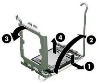
To replace the processor, reverse the removal procedures. Be sure that the triangle icon on the corner of the processor (1) aligns with the triangle icon on the processor socket (2).


NOTE: After installing a new processor onto the system board, always update the system ROM to ensure that the latest version of the BIOS is being used on the computer. You can find the latest system BIOS on the web at: https://support.hp.com/us-en.
Power supply
To remove the power supply, use these procedures.
Table 4-13 Power supply descriptions and part numbers
| Description Spare part number |
| 240 W, 90% efficiency N05346-001 |
| 180 W, 92% efficiency N05345-001 |

NOTE: System board appearance can vary.
Before removing the power supply, follow these steps:
- Prepare the computer for disassembly (see Preparation for disassembly on page 22).
- Remove the access panel (see Access panel on page 22).
- Remove the optical drive (see Optical drive on page 25).
- Remove the front bezel (see Front bezel on page 26).
- Remove the WLAN module (see WLAN module on page 30).
Remove the power supply:
- Release the power supply P3 cable from the three retention clips (1) that are built into the fan hood.
- Release the power supply P1 cable from the three retention clips (2) that are built into the system chassis.
- Disconnect the power supply P1 (3) cable from the system board.
- Disconnect the power supply P2 (4) cable from the system board.
- Disconnect the power supply P3 (5) cable from the system board.

-
Remove the four Phillips screws (1) that secure the power supply to the computer.
-
Press and hold the power supply release tab (2).
- Slide the power supply toward the front of the system chassis (3), and then remove the power supply (4).

To install the power supply, reverse the removal procedures.
System board
To remove the system board, use these procedures.
Table 4-14 System board descriptions and part numbers
| Description Spare part number |
| System board |
| All system boards use the following part numbers: |
| xxxxxx-001: Non-Windows operating systems |
| xxxxxx-601: Windows operating system |
| For use in models with a standard BIOS with the following processors: 12000 series, G7400, G6900 M99753-001 |
| For use in models with a standard BIOS with the following processors: 12000 series, G7400, G6900 M99753-601 |
| For use in models with a NetClone BIOS with the following processors: 12000 series, G7400, G6900 M99754-001 |
| For use in models with a NetClone BIOS with the following processors: 12000 series, G7400, G6900 M99754-601 |
| For use in models with a standard BIOS with the following processors: 13000 series N33532-001 |
| For use in models with a standard BIOS with the following processors: 13000 series N33532-601 |
| For use in models with a NetClone BIOS with the following processors: 13000 series N33533-001 |
| For use in models with a NetClone BIOS with the following processors: 13000 series N33533-601 |
| For use in models with a standard BIOS with the following processors: 14000 series, 300 N81935-001 |
| For use in models with a standard BIOS with the following processors: 14000 series, 300 N81935-601 |
| For use in models with a NetClone BIOS with the following processors: 14000 series, 300 N81936-001 |
| For use in models with a NetClone BIOS with the following processors: 14000 series, 300 N81936-601 |

NOTE: All system board spare part kits include replacement thermal material.
System board appearance can vary.
Before removing the system board, follow these steps:
- Prepare the computer for disassembly (see Preparation for disassembly on page 22).
- Remove the access panel (see Access panel on page 22).
- Remove the optical drive (see Optical drive on page 25).
- Remove the front bezel (see Front bezel on page 26).
- Remove the WLAN module (see WLAN module on page 30).
- Remove the expansion card (see Expansion card on page 37).
- Remove the fan hood (see Fan hood on page 39).
- Remove the heat sink (see Heat sink on page 40).
Remove the system board:
- Disconnect the cables from the following connectors on the system board:
• Power supply P3 cable
- Fan cable
- Drive data cables
- Drive power cable
• Power supply P1 cable
- Speaker cable
• Power supply P2 cable
- Remove the five Torx15 screws that secure the system board to the system chassis.
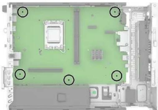
natural_image
Top-down view of a computer motherboard with green circuit board and labeled ports (no text or symbols)- Remove the system board by lifting it straight up.

natural_image
3D cutaway view of a computer motherboard showing internal components and a black arrow indicating a specific area (no text or symbols present)To install the system board, reverse the removal procedures.

NOTE: When replacing the system board, you must change the chassis serial number in the BIOS.
When replacing the system board, you must reprogram the SMBIOS information about the affected computer. Failure to reprogram the board will result in eventual failure, such as an activation failure (need to reactivate the system) or a system recovery failure.
Update SMBIOS information in Computer Setup.
Wireless antennas (select models only)
To remove the wireless antennas, use these procedures. The external connection antennas route from the WLAN module to the cable connectors on the front and rear panels of the computer.
Table 4-15 Wireless antennas and cables description and part number
| Description Spare part number |
| Wireless antennas and cables N09898-001 |
Before removing the wireless antennas, follow these steps:
- Prepare the computer for disassembly (see Preparation for disassembly on page 22).
- Remove the access panel (see Access panel on page 22).
- Remove the optical drive (see Optical drive on page 25).
- Remove the front bezel (see Front bezel on page 26).
Remove the wireless antennas:
- Disconnect the AUX antenna cable from the WLAN module (1).
- Release the AUX antenna cable from the retention clip (2) that is built into the system chassis.
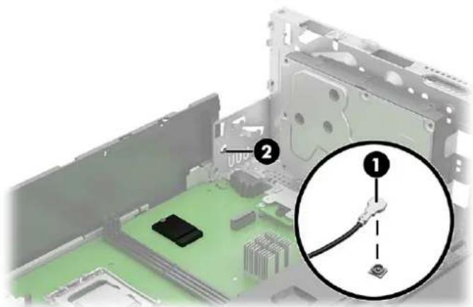
- Release the AUX antenna cable through the opening in the system chassis (1).
- Remove the slotted Torx screw (2) that secures the AUX antenna transceiver to the system chassis.
- Remove the AUX antenna cable and transceiver (3).

- Disconnect the MAIN antenna cable (1) from the WLAN module.
- Release the MAIN antenna cable from the routing channel (2) that is built into the system chassis.

- Press down on the tab (1) on the transceiver cover, and then remove the cover (2) by swinging the top edge down and away from the system chassis.
- Remove the slotted Torx screw (3) that secures the MAIN antenna transceiver to the system chassis.
- Release the MAIN antenna cable through the opening in the system chassis (4).
- Remove the MAIN antenna cable and transceiver (5).

To install the wireless antenna, reverse the removal procedures.

NOTE: If you install an external antenna, the recommended distance to place the antenna from the computer is 30 cm (12 in).
Troubleshooting without diagnostics5
Use these sections to identify and correct minor problems.
CAUTION: Misuse of the computer or failure to establish a safe and comfortable work environment can result in discomfort or serious injury. See the Safety & Comfort Guide at http://www.hp.com/ergo for more information about choosing a workspace and creating a safe and comfortable work environment. For more information, see the Safety & Regulatory Information guide.
Before you call for technical support
If you are having problems with the computer, try these solutions to isolate the exact problem before calling for technical support.
- Run the HP diagnostic tool.
- Run the hard drive self-test in Computer Setup.
- Check the power light on the front of the computer to see if it is blinking red. The blinking lights are error codes that will help you diagnose the problem.
- If you are working on a network, plug another computer with a different cable into the network connection. There might be a problem with the network plug or cable.
- If you recently added new hardware, remove the hardware and see if the computer functions properly.
- If you recently installed new software, uninstall the software and see if the computer functions properly.
- Boot the computer to the Safe Mode to see if it will boot without all of the drivers loaded. When booting the operating system, use "Last Known Configuration."
• See the comprehensive online technical support at http://www.hp.com/support.
Access HP Business Solutions at https://www.hp.com/us-en/solutions/business-solutions.html for the latest online support information, software and drivers, proactive notification, and worldwide community of peers and HP experts.
If it becomes necessary to call for technical assistance, be prepared to do the following tasks to ensure that your service call is handled properly:
- Be in front of your computer when you call.
- Before you call, write down the computer serial number and product ID number.
- Spend time troubleshooting the problem with the service technician.
- Restore the system from the Recovery Disc Set that you created or restore the system to its original factory condition in System Software Requirement Disks (SSRD).

IMPORTANT: Restoring the system will erase all data on the hard drive. Be sure to back up all data files before running the restore process.

NOTE: For sales information and warranty upgrades (Care Packs), call your local authorized service provider or dealer.
Helpful hints
If you encounter problems with the computer or software, see this list of general suggestions before taking further action.
- Check that the computer is plugged into a working electrical outlet.
- Check that the computer is turned on and the white power light is on.
- Check the power light on the front of the computer to see if it is blinking red. The blinking lights are error codes that help you diagnose the problem.
- Press and hold any key if the system beeps. Then the keyboard should be operating correctly.
- Check all cable connections for loose connections or incorrect connections.
- Wake the computer by pressing any key on the keyboard or pressing the power button. If the system remains in suspend mode, shut down the computer by pressing and holding the power button for at least four seconds, and then press the power button again to restart the computer. If the system does not shut down, unplug the power cord, wait a few seconds, and then plug it in again. The computer will restart if it is set to turn on automatically as soon as power is restored in Computer Setup.
- Be sure that all the needed device drivers have been installed. For example, if you are using a printer, you need a driver for that model printer.
- Remove all bootable media (such as a USB device) from the system before turning it on.
- If you have installed an operating system other than the factory-installed operating system, check to be sure that it is supported on the system.
NOTICE: When the computer is plugged into an AC power source, voltage is always being applied to the system board. You must disconnect the power cord from the power source before opening the computer to prevent system board or component damage. After you plug in the AC power cord, wait five seconds before you press the power button.
Solving general problems
You might be able to easily resolve the general problems described in this section. If a problem persists and you cannot resolve it yourself or if you feel uncomfortable about performing the operation, contact an authorized dealer or reseller.

CAUTION: When the computer is plugged into an AC power source, voltage is always being applied to the system board. To reduce the risk of personal injury from electrical shock, hot surfaces, or both, be
sure to disconnect the power cord from the AC outlet and allow the internal system components to cool before touching.
Cannot access the Computer Setup (F10) Utility when booting the computer
Use this information to troubleshoot the computer.
| SolutionCause | |
| The Computer Setup (F10) Utility is set to Fast Boot, causing the F10 access screen to display too briefly when booting the computer. | Before turning on the computer, press and hold f10. Turn on the computer and continue to hold F10 until the Computer Setup (F10) Utility is displayed.- or -Follow the Windows® instructions for rebooting the computer into the Computer Setup (F10) Utility. |
Computer appears locked up and will not turn off when the power button is pressed
Use this information to troubleshoot the computer.
| SolutionCause | |
| Software control of the power switch is not functional. | 1. Press and hold the power button for at least 4 s until the computer turns off. |
| 2. Disconnect the power cord from the electrical outlet. |
Computer will not respond to keyboard or mouse
Use this information to troubleshoot the computer.
| Cause | Solution |
| Computer is in Sleep state. | To resume from Sleep state, press the power button. |
| IMPORTANT: When attempting to resume from Sleep state, do not hold down the power button for more than 4 s. Otherwise, the computer shuts down and you lose any unsaved data. | |
| Restart computer.System has locked up. | |
| Disconnect, and then reconnect USB cables to keyboard and mouse.USB cables may not |
Computer date and time display is incorrect
Use this information to troubleshoot the computer.
| Cause | Solution |
| RTC (real-time clock) battery may need to be replaced. | Reset the date and time under Control Panel. (Computer Setup can also be used to update the RTC date and time.) If the problem persists, replace the RTC battery. See the Removal and Replacement section for instructions about installing a new battery, or contact an authorized dealer or reseller for RTC battery replacement.To access Control Panel in Windows, type control panel in the taskbar search box, and then select Control Panel. |
There is no sound or sound volume is too low
Use this information to troubleshoot the computer.
| SolutionCause | |
| System volume might be set low or muted. | 1. Check the front panel to see if an amber light indicates the system has been muted. Tap the touch-sensitive button to toggle the mute on and off.2. Check the Computer Setup settings to be sure that the internal system speaker is not muted. This setting does not affect the external speakers.3. Be sure that the external speakers are properly connected and powered on and that the speakers' volume control is set correctly.4. Use the system volume control available in the operating system to be sure that the speakers are not muted or to increase the volume. |
Cannot remove computer cover or access panel
Use this information to troubleshoot the computer.
| SolutionCause | |
| Smart Cover Lock, featured on some computers, is locked. | Unlock the Smart Cover Lock using Computer Setup.In case of forgotten password, power loss, or computer malfunction, you must manually disable the Smart Cover lock. A key to unlock the Smart Cover Lock is not available from HP. Keys are typically available from a hardware store. |
Poor performance
Use this information to troubleshoot the computer.
| Cause | Solution |
| Processor is too hot. | 1. Be sure that airflow to the computer is not blocked. Leave a 10.2 cm (4 inch) clearance on all vented sides of the computer to permit the required airflow.2. Be sure that fans are connected and working properly (some fans only operate when needed).3. Be sure that the processor heat sink is installed properly. |
| Transfer data from the hard drive to create more space on the hard drive. Hard drive is | |
| Add more memory.Low on memory. | |
| Defragment hard drive.Hard drive fragmented. | |
| reserved memory back to the system. | Restart the computer.Program previously accessed did not release |
| Run virus protection program.Virus resident on the hard drive. | |
| Too many applications running. | 1. Close unnecessary applications to free memory.2. Add more memory.3. Some applications run in the background and can be closed by right-clicking their corresponding icons in the task tray. |
Some software applications, especially games, are stressful on the graphics subsystem.
-
Lower the display resolution for the current application or consult the documentation that came with the application for suggestions on how to improve performance by adjusting parameters in the application.
-
Add more memory.
-
Upgrade the graphics solution.
Restart the computer.Cause unknown.
System does not turn on and the lights on the front of the computer are not blinking
Use this information to troubleshoot the computer.
| SolutionCause | |
| System unable to power on. | Press and hold the power button for fewer than 4 s. If the hard drive light turns white:1. If the computer has a voltage selector, check that the voltage selector (located on the rear of the power supply) is set to the appropriate voltage. The proper voltage setting depends on your region.2. Remove the expansion cards one at a time until the 5V_aux light on the system board turns on.3. Replace the system board.ORPress and hold the power button for less than 4 s. If the hard drive light does not turn white:1. Check whether the unit is plugged into a working AC outlet.2. Open the access panel and check that the power button cable is properly connected to the system board.3. Check that the power supply cables are properly connected to the system board.4. Check to see if the 5V_aux light on the system board is turned on. If it is turned on, replace the power button assembly.5. If the 5V_aux light on the system board is off, replace the power supply.6. Replace the system board. |
Solving power problems
These tables provide common causes and solutions for power problems.
Power supply shuts down intermittently
Use this information to troubleshoot the computer.
| SolutionCause | |
| voltage selector switch on the rear of the computer chassis (select products only) is not switched to the correct line voltage (115 V or 230 V). | Select the proper AC voltage using the selector switch.If the computer has a voltage s |
| Internal power supply fault. | Replace the power supply.Power supply will not turn on because of |
Solving hard drive problems
These tables provide common causes and solutions for hard drive problems.
Hard drive error occurs
Use this information to troubleshoot the computer.
| SolutionCause | |
| Hard disk has bad sectors or has failed. | 1. In Windows, type file in the taskbar search box, and then select File Explorer from the list of applications. In the left column, expand This PC, right-click a drive, select Properties, and then select the Tools tab. Under Error checking, select Check.2. Use a utility to locate and block usage of bad sectors. If necessary, reformat the hard disk. |
Disk drive transaction problem
Use this information to troubleshoot the computer.
| Cause | Solution |
| Either the directory structure is bad or there is a problem with a file. | In Windows, type file in the taskbar search box, and then select File Explorer from the list of applications. In the left column, expand This PC, right-click a drive, select Properties, and then select the Tools tab. Under Error checking, select Check. |
Drive not found (identified)
Use this information to troubleshoot the computer.
| Cause | Solution |
| Check cable connections.Cable could be loose. | |
| The system might not have automatically recognized a newly installed device. | See reconfiguration directions in theSolving hardware installation problems on page 59section. If the system still does not recognize the new device, check to see if the device is listed in Computer Setup. If it is listed, the probable cause is a driver problem. If it is not listed, the probable cause is a hardware problem.If this is a newly installed drive, run the Computer Setup utility, and add a POST delay under Advanced > Boot Options. |
| The device is attached to a SATA port that has been hidden in Computer Setup. | Run the Computer Setup utility and be sure that Device Available is selected for the device's SATA port in Advanced > Port Options. |
Drive responds slowly immediately after startup.
Run Computer Setup and increase the POST Delay in Advanced > Boot Options.
Nonsystem disk/NTLDR missing message
Use this information to troubleshoot the computer.
| SolutionCause | |
| drive, but the hard drive might have been damaged. | Perform Drive Protection System (DPS) testing in system ROM.The system is trying to state. |
| System files missing or not properly installed. | 1. Insert bootable media and restart the computer.2. Boot to the windows installation media, and select the recovery option. If only a restore kit is available, then select the File Backup Program option, and then restore the system.3. Install system files for the appropriate operating system. |
| Hard drive boot has been disabled in Computer Setup. | Run the Computer Setup utility, and enable the hard drive entry in the Advanced >Boot Options list. |
| Bootable hard drive is not attached as first in a multiple hard drive configuration. | If attempting to boot from a hard drive, be sure that it is attached to the system board dark blue SATA connector. |
| Bootable hard drive is not listed first in the Boot Order. | Run the Computer Setup utility, and select Advanced >Boot Options, and be sure that the bootable hard drive is listed immediately under the Hard Drive entry. |
Computer will not boot from hard drive
Use this information to troubleshoot the computer.
| Cause | Solution |
| The device is attached to a SATA port that has been hidden in Computer Setup. | 1. Check SATA cable connections.2. Run the Computer Setup utility, and be sure that Device Available is selected for the device's SATA port in Advanced > Port Options. |
| Boot order is not correct. | Run the Computer Setup utility, and change the boot sequence in Advanced > Boot Options. |
| Hard drive is damaged. | Observe whether the front panel power light is blinking red and whether any beeps are heard.See the Worldwide Limited Warranty for terms and conditions. |
Computer seems to be locked up
Use this information to troubleshoot the computer.
| Cause | Solution |
| Program in use has stopped responding to commands. | 1. Use the task manager to close programs that do not respond.2. Attempt the normal Windows shutdown procedure. If this fails, press the power button for 4 or more seconds to turn off the power. To restart the computer, press the power button again. |
Solving audio problems
If the computer has audio features and you encounter audio problems, see the common causes and solutions listed in these tables.
Sound cuts in and out
Use this information to troubleshoot the computer.
| SolutionCause | |
| open applications. | Shut down all open processor-intensive applications. Processor resources are being u |
Sound does not come out of the speaker or headphones
Use this information to troubleshoot the computer.
| SolutionCause | |
| Software volume control is turned down or muted. | Double-click the Speaker icon on the taskbar, be sure that Mute is not selected, and use the volume slider to adjust the volume. You can perform this action with the touch-sensitive buttons on the front of the computer. |
| Audio is hidden in Computer Setup. | Enable the audio in Computer Setup: Advanced > Built-in Device Options. |
| Turn on the external speakers.The external speakers are not turned on. | |
| Headphones or devices connected to the line-out connector mute the internal speaker. | Turn on and use headphones or external speakers, if connected, or disconnect headphones or external speakers. |
| Computer is in the Sleep state. | Press the power button to resume from the Sleep state. |
| IMPORTANT: When attempting to resume from the Sleep state, do not hold down the power button for more than 4 seconds. Otherwise, the computer will shut down, and you will lose any unsaved data. | |
| Internal speaker is disabled in Computer Setup. | Enable the internal speaker in Computer Setup. Select Advanced > Built-In Device Options. |
| output device is used. | Be sure that the application has selected the correct audio device.Some applications are not considered. |
| to use a different audio device as the default output device than what is expected. | Set the operating system to use the correct audio device.The operating system controls the output device. |
Computer appears to be locked up while recording audio
Use this information to troubleshoot the computer.
| Cause | Solution |
| The hard disk might be full. | Before recording, be sure that there is enough free space on the hard disk. You can also try recording the audio file in a compressed format. |
Line-in jack is not functioning properly
Use this information to troubleshoot the computer.
| SolutionCause | |
| Jack has been reconfigured in the audio driver or application software. | In the audio driver or application software, reconfigure the jack or set the jack to its default value. |
Solving printer problems
If you encounter printer problems, see the documentation that came with the printer and the common causes and solutions listed in these tables.
Printer will not print
Use this information to troubleshoot the computer.
| SolutionCause | |
| Turn the printer on and be sure that it is online.Printer is not turned on and online. | |
| The correct printer drivers for the application are not installed. | 1. Install the correct printer driver for the application.2. Try printing using the MS-DOS command:DIR C:\> [printer port]where [printer port] is the address of the printer being used. If the printer works, reload the printer driver.To run MS-DOS commands, press the Windows key + r, type cmd in the Open box, and then select OK. |
| made the connection to the printer. | Make the proper network connections to the printer.If you are on a network, you might no |
| Run printer self-test.Printer might have failed. | |
| Check the paper tray, and refill it if it is empty.The printer might be out of paper. |
Printer will not turn on
Use this information to troubleshoot the computer.
| Cause | Solution |
| Reconnect all cables, and check the power cord and electrical outlet. The cables might nc |
Printer prints garbled information
Use this information to troubleshoot the computer.
| Cause | Solution |
| not installed. | Install the correct printer driver for the application.The correct printer driver for the appli |
| Reconnect all cables.The cables might not be connected properly. | |
| Reset the printer by turning it off for 1 min, and then turn it back on.Printer memory might |
Solving keyboard and mouse problems
If you encounter keyboard or mouse problems, see the documentation that came with the equipment and the common causes and solutions listed in these tables.
Keyboard commands and typing are not recognized by the computer
Use this information to troubleshoot the computer.
| SolutionCause | |
| Keyboard connector is not properly connected. | Shut down the computer, reconnect the keyboard, and then restart the computer. |
| Program in use has stopped responding to commands. | Shut down your computer using the mouse, and then restart the computer. |
| See the Worldwide Limited Warranty for terms and conditions. Keyboard needs repairs | |
| Computer is in the Sleep state. | Press the power button to resume from the Sleep state. |
| IMPORTANT: When attempting to resume from the Sleep date, do not hold down the power button for more than 4 seconds. Otherwise, the computer will shut down, and you will lose any unsaved data. |
Mouse does not respond to movement or is too slow
Use this information to troubleshoot the computer.
| Cause | Solution |
| Mouse connector is not properly plugged into the back of the computer. | Shut down the computer using the keyboard.1. Press thectrl and esckeys at the same time (or press theWindows logo key) to display the Start menu.2. Use thearrowkeys to scroll to and select the power icon at the top right on the menu, and then pressenter.3. Use thearrowkeys to select Shut Down, and then pressenter.4. After the shutdown is complete, plug the mouse connector into the back of the computer (or the keyboard) and restart. |
| Program in use has stopped responding to commands. | Shut down the computer using the keyboard, and then restart the computer. |
| See the Worldwide Limited Warranty for terms and conditions.Mouse might need repa | |
| Computer is In the Sleep state. | Press the power button to resume from the Sleep state.IMPORTANT:When attempting to resume from the Sleep state, do not hold down the power button for more than 4 seconds. Otherwise, the computer will shut down, and you will lose any unsaved data. |
| resynchronize the mouse with the computer. | Follow the instructions that came with the mouse.If using a wireless mouse, you might |
Solving hardware installation problems
You might need to reconfigure the computer when you add or remove hardware, such as an additional drive or expansion card.
If you install a plug and play device, Windows automatically recognizes the device and configures the computer. If you install a device that is not plug and play, you must reconfigure the computer after completing installation of the new hardware. In Windows, use the Add Hardware Wizard, and follow the instructions that appear on the screen.
To open the Add Hardware Wizard, open a command prompt and type.
WARNING! When the computer is plugged into an AC power source, voltage is always applied to the system board. To reduce the risk of personal injury from electrical shock, hot surfaces, or both, be sure to disconnect the power cord from the AC outlet and allow the internal system components to cool before touching.
A new device is not recognized as part of the system
Use this information to troubleshoot the computer.
| SolutionCause | |
| Cables of new external device are loose or power cables are unplugged. | Be sure that all cables are properly and securely connected and that pins in the cable or connector are not bent down. |
| Power switch of new external device is not turned on. | Turn off the computer, turn on the external device, and then turn on the computer to integrate the device with the computer system. |
| When the system advised you of changes to the configuration, you did not accept them. | Reboot the computer and follow the instructions for accepting the changes. |
| A plug and play board might not automatically configure when added if the default configuration conflicts with other devices. | Use Windows Device Manager to clear the automatic settings for the board, and choose a basic configuration that does not cause a resource conflict. You can also use Computer Setup to reconfigure or disable devices to resolve the resource conflict.To access Device Manager In Windows, type device manager In the taskbar search box, and then select Device Manager from the list of applications. |
| USB ports on the computer are disabled in Computer Setup. | Run the Computer Setup utility and ensure that Device available is selected for appropriate USB ports under Advanced > Port Options. |
Computer will not start
Use this information to troubleshoot the computer.
| Cause | Solution |
| Incorrect memory modules were used in the upgrade, or memory modules were installed in the wrong location. | 1. Review the documentation that came with the system to determine if you are using the correct memory modules and to verify the proper installation. |
| NOTE: DIMM1 or XMM1 must always be installed. DIMM1 must be installed before DIMM3. | |
| 2. Observe the beeps and lights on the front of the computer. Beeps and blinking lights are codes for specific problems. | |
| 3. If you still cannot resolve the issue, contact Customer Support. |
Solving network problems
Some common causes and solutions for network problems are listed in these tables. The guidelines do not discuss the process of debugging the network cabling.
Network driver does not detect network controller
Use this information to troubleshoot the computer.
| SolutionCause | |
| Network controller is disabled. | 1. Run Computer Setup and enable network controller.2. Enable the network controller in the operating system using Device Manager.To access Device Manager In Windows, type device manager in the taskbar search box, and then selectDevice Managerfrom the list of applications. |
| Incorrect network driver. | Check the network controller documentation for the correct driver or obtain the latest driver from the manufacturer's website. |
Network status link light never blinks
Use this information to troubleshoot the computer.

NOTE: The network status light is supposed to blink when there is network activity.
| SolutionCause | |
| Check cabling and network equipment for proper connection.No active network is detected. | |
| Network controller is not set up properly. | Check for the device status within Windows, such as Device Manager for driver load and the Network Connections applet within Windows for link status.To access Device Manager in Windows,type device manager in the taskbar search box, and then selectDevice Manager from the list of applications. |
| Network controller is disabled. | 1.Run Computer Setup and enable network controller.2.Enable the network controller in the operating system using Device Manager.To access Device Manager in Windows,type device manager in the taskbar search box, and then selectDevice Manager from the list of applications. |
| Reinstall network drivers.Network driver is not properly loaded. | |
| System cannot autosense the network. | Disable autosensing capabilities, and force the system into the correct operating mode. |
Diagnostics reports a failure
Use this information to troubleshoot the computer.
| Cause | Solution |
| The cable is not securely connected. | Be sure that the cable is securely attached to the network connector and that the other end of the cable is securely attached to the correct device. |
| connector. | Be sure that the cable is attached to the correct connector.The cable is attached to the |
| There is a problem with the cable or a device at the other end of the cable. | Be sure that the cable and device at the other end are operating correctly. |
Diagnostics passes, but the computer does not communicate with the network
Use this information to troubleshoot the computer.
| SolutionCause | |
| Network drivers are not loaded, or driver parameters do not match current configuration. | Be sure that the network drivers are loaded and that the driver parameters match the configuration of the network controller.Be sure that the correct network client and protocol are installed. |
| The network controller is not configured for this computer. | Select the Network and Sharing Center icon in the Control Panel, and configure the network controller.To access Control Panel in Windows, type control panel in the taskbar search box, and then select Control Panel from the list of applications. |
Network controller stopped working when an expansion board was added to the computer
Use this information to troubleshoot the computer.
| SolutionCause | |
| The network controller requires drivers. | Verify that the drivers were not accidentally deleted when the drivers for a new expansion board were installed. |
Network controller stops working without apparent cause
Use this information to troubleshoot the computer.
| Cause | Solution |
| The cable is not securely connected. | Be sure that the cable is securely attached to the network connector, and that the other end of the cable is securely attached to the correct device. |
| Contact an authorized service provider.The network controller is defective. |
Cannot connect to network server when attempting remote system installation
Use this information to troubleshoot the computer.
| Cause | Solution |
| The network controller is not configured properly. | Verify that network connectivity exists, a DHCP Server is present, and the Remote System Installation Server contains the network interface card (NIC) drivers for your NIC. |
System setup utility reports unprogrammed EEPROM
Use this information to troubleshoot the computer.
| Cause | Solution |
| Contact an authorized service provider.Unprogrammed EEPROM. |
Solving memory problems
If you encounter memory problems, some common causes and solutions are listed in these tables.

IMPORTANT: Depending on the Management Engine (ME) settings, power can still be supplied to the DIMMs when the computer is turned off. To avoid damage to the DIMMs or the system board, you must unplug the computer power cord before attempting to reseat, install, or remove a memory module.
For those systems that support error correction code (ECC) memory, HP does not support mixing ECC and non-ECC memory. Otherwise, the computer will not boot the operating system.

NOTE: The memory count will be affected by configurations with the ME enabled. The ME uses 8 MB of system memory in single-channel mode or 16 MB of memory in dual-channel mode to download, decompress, and execute the ME firmware for Out-of-Band (OOB), third-party data storage, and other management functions.
System will not boot or does not function properly after installing additional memory modules
Use this information to troubleshoot the computer.
| SolutionCause | |
| A memory module is not installed in the DIMM1 or XMM1 socket. | Verify that a memory module is installed in the DIMM1 or XMM1 socket on the system board. This socket must be populated with a memory module. |
| Memory module is not the correct type or speed grade for the system, or the new memory module is not seated properly. | Replace module with the correct industry-standard device for the computer. On some models, ECC and non-ECC memory modules cannot be mixed. |
Out of memory error
Use this information to troubleshoot the computer.
| Cause | Solution |
| You have run out of memory to run the application. | Check the application documentation to determine the memory requirements. |
Memory count during POST is wrong
Use this information to troubleshoot the computer.
| Cause | Solution |
| The memory modules might not be installed correctly. | Check that the memory modules have been installed correctly and that proper modules are used. |
| memory. | No action required.Integrated graphics might use system |
Insufficient memory error during operation.
Use this information to troubleshoot the computer.
| SolutionCause | |
| programs (TSRs) are installed. | Delete any TSRs that you do not need.Too many Terminate and Stay Resident |
| You have run out of memory for the application. | Check the memory requirements for the application or add more memory to the computer. |
Solving USB flash drive problems
If you encounter USB flash drive problems, common causes and solutions are listed in these tables.
USB flash drive is not seen as a drive letter in Windows
Use this information to troubleshoot the computer.
| SolutionCause | |
| not available. | Change the default drive letter for the flash drive in Windows.The drive letter after the last |
USB flash drive not found (identified)
Use this information to troubleshoot the computer.
| Cause | Solution |
| The device is attached to a USB port that has been hidden in Computer Setup. | Run the Computer Setup utility and enable the USB ports in Advanced > Port Options. |
| The device was not properly seated before startup. | Be sure that the device is fully inserted into the USB port before applying power to the system |
System will not boot from USB flash drive
Use this information to troubleshoot the computer.
| Cause | Solution |
| Boot order is not correct. | Run the Computer Setup utility, and change the boot sequence in Advanced > Boot Options. |
| Removable Media Boot is disabled in the Computer Setup utility. | Run the Computer Setup utility, and enable booting to removable media in Advanced > Boot Options. Be sure that USB is enabled in Storage > Boot Order. |
The computer boots to DOS after making a bootable flash drive
Use this information to troubleshoot the computer.
| Cause | Solution |
| Install the flash drive only after the operating system boots.Flash drive is bootable. | |
| Try a different flash drive.Flash drive is defective. |
Solving internet access problems
If you encounter internet access problems, consult your internet service provider (ISP), or see the common causes and solutions listed in these tables.
Unable to connect to the internet
Use this information to troubleshoot the computer.
| SolutionCause | |
| set up properly. | Verify Internet settings, or contact your ISP for assistance.Internet Service Provider (ISP) |
| Verify that the web browser is installed and set up to work with your ISP.Web browser i | |
| Cable/DSL modem is not plugged in. | Plug in the cable/DSL modem. You should see a power light on the front of the cable/DSL modem. |
| Cable/DSL service is not available or has been interrupted due to bad weather. | Try connecting to the internet at a later time or contact your ISP. If the cable/DSL service is connected, the cable light on the front of the cable/DSL modem will be on. |
| The CAT5 UTP cable is disconnected. | Connect the CAT5 UTP cable between the cable modem and the computer's RJ-45 connector. If the connection is good, the PC light on the front of the cable/DSL modem will be on. |
| Contact your ISP for the correct IP address.IP address is not configured properly. | |
| Cookies are corrupted. A cookie is a small piece of information that a web server can store temporarily with the web browser. Cookies are useful because they enable the browser to remember some specific information that the Web server can later retrieve. | 1. Type control panel in the taskbar search box, and then select Control Panel from the list of applications.2. Select Internet Options.3. In the Browsing history section, select the Delete button.4. Select the Cookies and website data check box, and select the Delete button. |
Cannot automatically launch internet programs
Use this information to troubleshoot the computer.
| Cause | Solution |
| programs will start. | Log on to your ISP and launch the program.You must log on to your ISP before some |
Solving software problems
Most software problems occur as a result of these situations:
- The application was not installed or configured correctly.
- Insufficient memory is available to run the application.
- A conflict exists between applications.
- All the necessary device drivers might not have been installed.
- If you have installed an operating system other than the factory-installed operating system, it might not be supported on the system.
If you encounter software problems, see the applicable solutions listed in the following table.
Computer will not start up and the HP logo does not appear
Use this information to troubleshoot the computer.
| SolutionCause | |
| ROM issue - POST error has occurred. | Observe the beeps and lights on the front of the computer.See the Worldwide Limited Warranty for terms and conditions. |
"Illegal Operation has Occurred" error message is displayed
Use this information to troubleshoot the computer.
| SolutionCause | |
| Software being used is not Microsoft-certified for your version of Windows. | Verify that the software is certified by Microsoft for your version of Windows (see program packaging for this information). |
| If possible, save all data, close all programs, and restart the computer.Configuration files |
Computer Setup (F10) Utility6
This information provides details of the Computer Setup Utility.
- Change settings from the defaults or restore the settings to default values.
- View the system configuration, including settings for processor, graphics, memory, audio, storage, communications, and input devices.
-
Modify the boot order of bootable devices such as hard drives or USB flash media devices.
-
Enter the Asset Tag or property identification number assigned by the company to this computer.
- Enable the power-on password prompt during system restarts (warm boots) as well as during startup.
- Establish an administrator password that controls access to the Computer Setup (F10) Utility and the settings described in this section.
- Establish minimum requirements for valid passwords, including length and required types of characters.
- Secure integrated I/O functionality, including the serial, USB, or audio, or embedded NIC, so that they cannot be used until they are unsecured.
- Enable or disable different types of boot sources.
- Configure features such as Secure Boot, power management, virtualization support, and language and keyboard type used in Setup and POST.
- Replicate the system setup by saving system configuration information about a USB device and restoring it on one or more computers.
- Enable or disable DriveLock security or securely erase a hard drive.
Using Computer Setup (F10) Utilities
You can access Computer Setup only by turning the computer on or restarting the system.
To access the Computer Setup Utilities menu, complete these steps:
-
Turn on or restart the computer.
-
Repeatedly press f10 when the power button light turns white to access the utility.
You can also press esc to see a menu that allows you to access different options available at startup, including the Computer Setup utility.
A choice of four headings appears in the Computer Setup Utilities menu: Main, Security, Advanced, and UEFI Drivers.

NOTE: If you do not press f10 at the appropriate time, you must restart the computer and again repeatedly press f10 when the power button light turns white to access the utility.

NOTE: Selecting UEFI Drivers restarts the computer into the third-party option ROM management application. You can access this application directly by pressing f3 during startup.
-
Use the arrow (left and right) keys to select the appropriate heading. Use the arrow (up and down) keys to select the option you want, and then press enter. To return to the Computer Setup Utilities menu, press esc.
-
To apply and save changes, select Main > Save Changes and Exit.
-
If you have made changes that you do not want applied, select Ignore Changes and Exit.
- To restore settings from the Advanced and Main menus to original values, select Apply Factory Defaults and Exit.
- To restore settings from the Advanced and Main menus to those previously saved by Save Custom Defaults, select Apply Custom Defaults and Exit. If no custom defaults have been saved, factory defaults are used.

NOTE: You cannot modify settings in the Security menu by selecting Apply Defaults. You reset those values by selecting Restore Security Settings to Factory Defaults at the bottom of the Security menu.

NOTE: Not all settings shown in the following sections are available for all models.

IMPORTANT: Do not turn computer power off while the BIOS is saving the Computer Setup (F10) changes because the settings could become corrupted. It is safe to turn off the computer only after exiting the F10 Setup screen.
Computer Setup Main
This table provides information about the Computer Setup Main menu.

NOTE: Support for specific Computer Setup options can vary, depending on the hardware configuration.
Table 6-1 Computer Setup Main
| Option Description | |
| System Information | Lists all information in following list if Advanced System Information is selected. Lists smaller subset if Basic System Information is selected.Product nameInstalled memory sizeProcessor typeProcessor cache size (L1/L2/L3)Processor speedMicroCode revisionProcessor steppingMemory speedDIMM size (for each installed module)System BIOS versionME Firmware version (Intel® only)Video BIOS versionReference code revisionSuper I/O firmware versionUSB Type-C controller firmware versionBorn on dateSerial numberSKU numberUUID (Universally Unique Identifier)Asset tracking numberFeature byteBuild IDProduct familySystem board IDSystem board CT numberPanel typePanel serial numberIntegrated MAC Address |
| System Diagnostics | If the hard drive has the HP Advanced Diagnostics installed, the application launches. If HP Advanced Diagnostics is not installed, a basic version that is built into the BIOS provides the capability to perform the following functions:Memory TestHard Drive CheckLanguage |
| BIOS Event Log View BIOS Event LogDisplays a list of events, alerts, or warnings that have been logged since the log was last cleared.Export to USB KeySaves a file named BiosEventLog.txt containing the log entries to an inserted USB storage device.Clear BIOS Event Log on Next BootWhen selected, the BIOS clears the event log when the user saves and exits. Default is disabled. | |
| Option Description | |
| Update System BIOS | Lets you update the system BIOS fromwww.hp.comor another network server, from a removable USB drive, or from a file located on the hard drive.Check [current selection] for BIOS UpdatesThe string that appears here depends on the setting in BIOS Update Preferences.Lock BIOS VersionIf this option is selected, the system is locked to the current BIOS version, and updates are not allowed.Native OS Firmware Update ServiceAllows the operating system to drive firmware updates (for example, Windows Update).BIOS Rollback PolicyUnrestricted Rollback to older BIOS: Lets you roll back to any previous version of BIOS.Restricted Rollback to older BIOS: If selected, Minimum BIOS Version becomes active, which lets you manually enter the minimum BIOS version that you can roll back to.Minimum BIOS VersionDefaults to current version. Read-only unless restricted rollback is selected.Allow BIOS Updates Using a NetworkLets you configure scheduled, automatic BIOS updates through the network.BIOS Update PreferencesCheck for Update on Next Reboot: Default is disabled.BIOS Source: Lets you select either HP.com or a custom URL If Custom URL is selected, Edit Custom URL becomes active. HP recommends using a custom URL only for a managed IT environment.Automatic BIOS Update SettingAllows configuration of a periodic check for updates:NOTE: If Windows BitLocker Drive Encryption (BDE) is enabled, it must be temporarily suspended before the BIOS is flashed.Do not updateChecking for updates and prompt the user to accept or reject the update at that timeChecking for updates and install all new versionsChecking for updates and install only new versions marked importantBIOS Update FrequencyDailyWeeklyMonthly (default) |
| Option Description | |
| Update System BIOS Network Configuration Settings | |
| Lets you configure the network connection to the server that is the host for system firmware updates. | |
| Update BIOS Using Local Media | |
| Lets you access files on either USB storage or the hard drive. The HP BIOS Update and Recovery application included in BIOS Softpaqs at www.hp.com copies the BIOS file to the correct location on the hard drive or USB device. | |
| Change date and time Lets you update system date and time. | |
| System IDs Let you set the following values: | |
| •Asset Tracking Number | |
| •Ownership Tag | |
| Replicated Setup Back up current settings to USB device | |
| Saves system configuration to a formatted USB flash media device. | |
| Restore current settings from USB device | |
| Restores system configuration from a USB flash media device. | |
| Save Custom Defaults Saves the current system configuration settings as the custom default set. | |
| Apply Custom Defaults and Exit | Applies the custom default settings to the computer after rebooting. Does not apply to options in the Security menu. |
| Apply Factory Defaults and Exit | Restores the factory system configuration settings to the computer after rebooting. Does not apply to options in the Security menu. |
| Ignore Changes and Exit Exits Computer Setup without applying or saving any changes. | |
| Save Changes and Exit | Saves changes to current system configuration, exits Computer Setup, and reboots. |
Computer Setup Security
This table provides information about the Computer Setup Security menu.

NOTE: Support for specific Computer Setup options can vary, depending on the hardware configuration.
Table 6-2 Computer Setup Security
| Option Description | |
| Create BIOSAdministrator Password | Lets you set and enable a BIOS administrator password, which controls access to the following features:Setup Menu (F10)Third-Party Option ROM Management (F3)Update system ROMWMI commands that change system settingsBIOS Configuration Utility (BCU)Alternative power-on passwordNOTE: Creating a BIOS user disables the Fast Boot option. |
| Change BIOSAdministrator Password(This selection is active only if a BIOS administrator password is set.) | Lets you change the BIOS administrator password.You must know the current password to be able to change it. |
| Create POST Power-OnPassword | Lets you change or delete power-on password. The power-on password prompt appears after a power cycle or reboot. If the user does not enter the correct power-on password, the unit will not boot. |
| Change POST Power-OnPassword (This selection is active only if a BIOS administrator password is set.) | Lets you change the POST power-on password.You must know the current password to be able to change it. |
| Password Policies Let you set the guidelines for a valid password. Options include:Password minimum lengthRequires at least one symbolRequires at least one numberRequires at least one uppercase characterRequires at least one lowercase characterAllow spaces | |
| AdministratorAuthentication Policies | Let you set limitations on some boot features restricting them to admin only, including:Prompt for administrator authorization to access:-Boot menu in POST-System Recovery-Network boot-BIOS updateAllow the use of administrator credentials to modify the power-on password. |
Table 6-2 Computer Setup Security (continued)
| Option Description |
| Security Configuration TPM Embedded Security |
| • TPM Specification VersionDisplays the current Trusted Platform Module (TPM) version. |
| • TPM DeviceLets you set the TPM as available or hidden. Default is available. |
| • TPM StateSelect to enable the TPM. Default is disabled. |
| • Clear TPMSelect to reset the TPM to an unowned state. After the TPM is cleared, it is also turned off. To temporarily suspend TPM operations, turn the TPM off instead of clearing it. Default is no. |
| IMPORTANT: Clearing the TPM resets it to factory defaults and turns it off. You will lose all created keys and data protected by those keys. |
| • TPM Activation Policy-F1 to boot-Allow user to reject (default)-No prompts |
| BIOS Sure Start |
| • Verify Boot Block on every boot: Select to enable HP Sure Start. Default is disabled. |
| • BIOS Data Recovery Policy: Select Automatic or Manual to determine data recovery process. Manual recovery is intended only for situations when you want forensic analysis before HP Sure Start recovery. When this policy is set to manual, HP Sure Start will not correct any issues that are found until the local user enters the manual recovery key sequence. This can result in a computer that cannot boot until the manual recovery key sequence is entered. |
| • Network Controller Configuration Restore: Select to restore the network controller parameters to the factory state saved in the HP Sure Start Private nonvolatile (flash) memory. This setting is available only on computers with built-in NIC. |
| NOTE: This process can take up to 30 seconds. You need to restore this only when the Network Controller Configuration mismatch warning is set. |
| • Dynamic Runtime Scanning of Boot Block: Verifies the integrity of the BIOS boot block region several times each hour while the computer is running. Default is enabled. |
| • Sure Start BIOS Settings Protection: When enabled, HP Sure Start locks all critical BIOS settings and provides enhanced protection for these settings using nonvolatile (flash) memory. Default is off. |
| NOTE: An administrator password must be set to activate this setting. |
| • Sure Start Secure Boot Keys Protection: Saves a backup copy of Secure Boot Keys so that they can be recovered if someone attempts to alter them in an unauthorized manner. |
| • Enhanced HP Firmware Runtime Intrusion Prevention and Detection: Enables monitoring of HP system firmware executing out of main memory while the operating system is running. Any anomalies detected in HP system firmware that is active while the operating system is running will result in a Sure Start security event being generated. |
Table 6-2 Computer Setup Security (continued)
| Option Description | |
| Security Configuration | Sure Start Security Event Policy. Controls HP Sure Start behavior upon identifying a critical security event, such as any modification to HP firmware, while the operating system is running.Log Event Only: HP Sure Start will log all critical security events in the HP Sure Start audio log within the HP Sure Start nonvolatile (flash) memory.Log Event and notify user: In addition to logging all critical security events, HP Sure Start will notify the user within the operating system that a critical event has occurred.Log Event and power off system: In addition to logging all critical security events, HP Sure Start turns off the computer upon detecting a HP Sure Start Security Event. Because of the potential for data loss, HP recommends this setting only in situations where security integrity of the system is a higher priority than the risk of potential data loss.Sure Start Security Event Boot Notification: Lets you enable a warning message on the startup screen if a Sure Start event, such as BIOS recovery or Memory intrusion, occurs.Secure Boot Configuration.Lets you be sure that an operating system is legitimate before booting to it, making Windows resistant to malicious modification from preboot to full operating system booting, preventing firmware attacks. UEFI and Windows Secure Boot only allow code signed by preapproved digital certificates to run during the firmware and OS boot process.NOTE: An administrator password must be set to activate this setting. Secure Boot must also be enabled.Secure Boot: Default is disabled.Secure Boot Key Management: Lets you manage the custom key settings.NOTE: Access to these settings requires Sure Start Secure Boot Keys Protection to be disabled.-Import Custom Secure Boot Keys: Default is disabled.-Clear Secure Boot keys: Lets you delete any previously loaded custom boot keys. Clearing keys will disable secure boot. Default is disabled.-Reset Secure Boot keys to factory defaults: Default is disabled.-Enable MS UEFI CA key: Disabling this setting alters the Secure Boot key list to further restrict the allowed software components. Set this option to disable to support Device Guard. Default is enabled.-Ready BIOS for Device Guard Use: Requires BIOS Administrator password to be configured and Secure Boot to be enabled. |
| Security Configuration Secure Platform Management (SPM) | |
| ·SPM Current State: Displays the current state. Also lets you change the state. | |
| ·Unprovision SPM: Deprovisions SPM, which causes HP Sure Run to revert to the inactive state and return HP Sure Recover to default settings. | |
| ·HP Sure Run Current State: Displays the current state. Also lets you change the state. | |
| Deactivate HP Sure Run: Deactivates HP Sure Run without deprovisioning SPM. | |
| ·Smart Health Enable | |
| ·EBAM Current State: Displays the current state. Also lets you change the state. | |
| Disable EBAM: Disables Enhanced BIOS Authentication Mode (EBAM). | |
| ·Deactivate HP Sure Run: Requires BIOS Administrator password to be configured. | |
| ·Local Access Key: Indicates that the key is present. Also lets you clear the keys and reboot. | |
| Clear EBAM Local Access Keys and Reboot: Deletes all currently established local access keys created for Enhanced BIOS Authentication Mode (EBAM). | |
| Physical Presence Interface: When set to enabled, the user is notified at system power up when changes are made to system security policy. The user must manually agree to those changes before the change is confirmed. Default is enabled. | |
| Smart Cover: The Smart Cover Lock (select products only) is a software-controllable solenoid lock that restricts unauthorized access to the system's internal components. | |
| ·Cover Lock: Default is unlock. | |
| ·Cover Removal Sensor: Lets you disable the cover sensor or configure what action is taken if the computer cover is removed. Default is disabled. | |
| NOTE: Notify user alerts the user with a POST error on the first boot after the sensor detects removal of the cover. If the password is set, Administrator Password requires that the password be entered to boot the computer if the sensor detects that the cover has been removed. | |
| Trusted Execution Technology (TXT) | |
| Enables Trusted Execution Technology on select Intel-based systems. Default is disabled. | |
| NOTE: Enabling this feature disables OS management of the Trusted Platform Module (TPM), prevents a reset of the TPM, and constrains the configuration of VTx, VTd, and TPM. | |
| Intel Software Guard Extensions (SGX) | |
| Intel SGX is a set of processor code instructions that allows user-level code to allocate private regions of memory. Unlike normal process memory, SGX protects these private memory regions from processes running at higher privilege levels. | |
| ·Software control | |
| ·Disable | |
| ·Enable | |
| Full encryption of main memory (DRAM) (select products only) | |
| When selected, the computer stores all data to DRAM in an encrypted format. | |
| Utilities Hard Drive Utilities | |
| Save/Restore GPT of System Hard DriveEnabling this feature saves the GUID Partition Table (GPT) of the system hard drive. If the GPT is subsequently changed, the user is prompted to choose whether to restore GPT. Default is disabled.Boot Sector (GPT) Recovery PolicyAllows selection of the default action when a GPT event occurs.DriveLock/Automatic DriveLockAllows you to assign or modify a master or user password for hard drives. When this feature is enabled, the user is prompted to provide one of the DriveLock passwords during POST. If neither is successfully entered, the hard drive remains inaccessible until one of the passwords is successfully provided during a subsequent cold-boot sequence.NOTE: This selection appears only when at least one drive that supports the DriveLock feature is attached to the system.IMPORTANT: Be aware that these settings take place immediately. It is not necessary to save.IMPORTANT: Be sure to document the DriveLock password. Losing a DriveLock password will render a drive permanently locked.NOTE: Disable DriveLock on NVMe drives before using applications for hardware-based encryption.After you select a drive, the following options are available:-Set DriveLock Master Password. Sets the drive's master password but does not enable DriveLock.-Enable DriveLock. Sets the drive's user password and enables DriveLock.Secure EraseLets you select a hard drive to completely erase.After you erase a hard drive with a program that uses Secure Erase firmware commands, no file recovery program, partition recovery program, or other data recovery method can extract data from the drive.Allow OPAL Hard Drive SID AuthenticationBIOS supports drive encryption using the DriveLock feature by creating the storage device's ownership key. If BIOS creates the key, any third-party applications (Including other encryption software) are not allowed to perform certain drive operations such as establishing their own key using SID. Encryption software applications may or may not be limited by SID authentication lockout depending on how they are designed. Default is disabled. | |
| Absolute Persistence Module Current State | Shows the current state of the Absolute Persistence module.Yes: DisabledNo: Available |
| System Management Command | Allows authorized personnel to reset security settings during a service event. Default is enabled. |
| Restore Security Settings to Factory Default | This action resets security devices, clears BIOS passwords (not including DriveLock), and restores settings in the Security menu to factory defaults. |
Computer Setup Advanced
This table provides information about the Computer Setup Advanced menu.

NOTE: Support for specific Computer Setup options can vary, depending on the hardware configuration.
Table 6-3 Computer Setup Advanced (for advanced users)
| Option Heading | |
| Display Language | Lets you select the language of the menus in F10 Setup and the keyboard layout. |
| Scheduled Power-On This feature wakes the system when it is off at a specified date and time. | |
| Boot Options | Select the devices that the computer can boot from, as well as other options, including:Startup Delay (sec): Enabling this feature adds a user-specified delay to the POST process.One purpose for the delay is to provide additional time to activate hotkeys such as esc for the Startup Menu or f10 for Computer Setup.Fast Boot: Default is enabled.CD-ROM Boot (select products only): Default is enabled.USB Storage Boot: Default is enabled.Network (PXE) Boot: Default is enabled.After Power Loss: Default is Power Off.-Power off: Causes the computer to remain off when power is restored.-Power on: Causes the computer to turn on automatically as soon as power is restored.-Previous state: Causes the computer to turn on automatically as soon as power is restored, if it was on when power was lost.NOTE: If the system is configured to Power On from Keyboard Ports (see Power Management Options), this setting is forced to Power On.Prompt on Memory Size Change: Default is enabled.Prompt on Fixed Storage Change: Default is disabled.Audio Alerts During Boot: Default is enabled. When disabled, most audible beeps from errors, warnings, and password prompts during boot up are suppressed.Numlock on at boot: Default is disabled.UEFI Boot Order: Specify the order in which UEFI boot sources are checked for a bootable operating system image. The default boot order is:USB2. SATA DVD3. SATA hard drives4. M.2 devices5. Network boot |
| Boot Options | NOTE: Use the UP and DOWN arrows to highlight an item. Press enter to select. Use the UP and DOWN arrows to move a selected Item. Press f5 to enable or disable. Press esc to exit.NOTE: MS-DOS drive lettering assignments might not apply after a non-MS-DOS operating system has started.Shortcut to Temporarily Override Boot OrderTo boot one time from a device other than the default device specified in Boot Order, restart the computer and press esc (to access the Startup menu) and then f9 (Boot Menu), or only f9 (skipping the Startup menu) when the power button light turns white. After POST is completed, a list of bootable devices is displayed. Use the arrow keys to select the preferred bootable device and press enter. The computer then boots from the selected non-default device for this one time. |
| HP Sure Recover HP Sure Recover | |
| If enabled and HP Sure Recover is launched, the system firmware honors local and remote requests to reinstall the operating system. If it is disabled, all requests to reinstall the operating system are ignored. Default is enabled.Recover from NetworkAllows system firmware to retrieve the recovery agent from the network. If disabled, system firmware retrieves the recovery agent from a local drive. Default is enabled.Recover after Boot FailureIf enabled and no bootable UEFI operating system is found, system firmware launches HP Sure Recover. Default is disabled.Recover before Boot Failure RecoveryIf enabled and HP Sure Recover is launched because of a boot failure, the user is notified of the boot failure and asked to choose whether to start or cancel HP Sure Recover. This setting is displayed only if Recover after Boot Failure is selected.Recovery AgentDisplays recovery agent information. This information is displayed only if Recover from Network is selected.Recovery ImageDisplays recovery image information. This information is displayed only if Recover from Network is selected.OS Recovery Image Version.Display the version of the recovery image stored in the embedded secure storage device. This information is displayed only if an embedded secure storage device is installed.OS Recovery Driver VersionDisplay the version of the recovery driver stored in the embedded secure storage device. This information is displayed only if an embedded secure storage device is installed. | |
| System Options Configure storage controller for Intel OptaneTM (Intel products only) | |
| Enables the Intel Optane memory module. | |
| Configure storage controller for RAID | |
| Enables RAID. Default is enabled. | |
| Limit PCIe Speed (workstation models only) | |
| Lets you restrict the maximum speed of the PCI Express devices to previous generations. The following settings are possible: | |
| ●Auto | |
| ●Gen 1 (2.5 Gbps) | |
| ●Gen 2 (5 Gbps) | |
| ●Gen 3 (8 Gbps) | |
| Turbo-boost (Intel products only) | |
| Allows Intel Turbo Boost Technology to improve performance when operation conditions allow. Default is enabled. | |
| Hyperthreading (Intel products only) | |
| Lets you control processor capability. Default is enabled. | |
| Virtualization Technology (VTx) (Intel only) | |
| Controls the virtualization features of the processor. Changing this setting requires turning the computer off and then back on. Default is disabled. | |
| Virtualization Technology for Directed I/O (VTd) (Intel only) | |
| Controls virtualization DMA remapping features of the chipset. Changing this setting requires turning the computer off and then back on. Default is disabled. | |
| SVM CPU Virtualization (AMD® products only) | |
| Enables AMD-V and AMD-Vi virtualization features on AMD-based systems | |
| Enhanced Hello Sign-in (systems with supporting hardware for biometric identification only) | |
| Allows for secure logon using the Windows Hello feature. | |
| DMA Protection | |
| Enables DMA redirection using IOMMU for enhanced security. Default is enabled. | |
| NOTE: Requires that VTd is enabled. | |
| Pre-boot DMA protection | |
| Secures memory access through DMA to allowed regions prior to operating system startup. | |
| Full encryption of main memory (DRAM) (select products only) | |
| Stores all data to DRAM in an encrypted format. Default is enabled. | |
| PCI slots (vary by product) | |
| Lets you enable or display PCI slots. Default is enabled. | |
Table 6-3 Computer Setup Advanced (for advanced users) (continued)
| Option Heading |
| System Options M.2 slots (vary by product) |
| Let you enable or display M.2 slots. Default is enabled. |
| Performance Control (High Performance Mode/Performance Mode/Quiet Mode) |
| Select Quite Mode to prioritize acoustics. Select Performance Mode for a balance between performance and acoustics. Select High Performance Mode to prioritize performance. |
| Power Button Override (disable/4 sec/15 sec/30 sec) |
| Lets you enable and select the number of seconds you have to hold down the power button for it to force the system to turn off. Default is 4 sec. |
| USB Type-C Connector System Software Interface (UCSI) (select products only) |
| Allows UCSI to be exposed to the operating system (ACPI table). |
| HP Application Driver |
| Provides ACPI structure to enable HP common software application framework. The driver is provided in the latest HP support software that you can download from the web. |
| NOTE: Device Manager shows an alert if this setting is enabled without the HP application driver installed. |
| AMD DASH |
| Lets you enable AMD Remote system management capability. Default is disabled. |
| Hardware enabled Spectre Variant 2 Mitigation |
| Enables Single Thread Indirect Branch Predictor (STIBP) functionality in AMD processors. Default is disabled. |
| Built-In Device Options Embedded LAN Controller (select products only)Select to show the device in the operating system. Default is enabled.Wake On LANLets you either disable the Wake On LAN feature or configure where the computer boots, including the network or hard drive. Default is boot to network.LAN Controller Option (1)(2) (select products only)Enables the integrated network controller in the designated rear option slot.Dust Filter (select products only)Default is disabled.Dust Filter Reminder (Days) (select products only)Default Is 60.Allow No Panel configuration (All-in-One 1000 series models only)Allows operation of the base unit without a boot warning when the panel is not installed.Integrated Video (models with discrete graphics)Disables the integrated video device. When not using integrated video, disabling the integrated video will free some system memory.VGA Boot Device (models with discrete graphics)Selects the graphics controller to use as the primary VGA device during boot-up when there are multiple graphics devices. The firmware can use only one graphics device when booting up.Video Memory SizeLets you manage graphics memory allocation. The value you choose is allocated permanently to graphics and is unavailable to the operating system.Integrated CameraLets you disable the integrated camera. Default is enabled.Audio DeviceSelect to show audio devices in the operating system, including integrated microphone, internal speakers, and headphone out. When selected, operating system visibility of each audio device is controlled independently. When this setting is cleared, all audio devices are hidden from the operating system. Individual audio device settings are also disabled. Default is enabled.MicrophoneClear to disable the integrated microphone. This does not affect devices plugged into audio jacks. The disable and lock setting prevents other audio ports from being remapped to the microphone function in the operating system. Default is enabled.Internal Speakers (does not affect external speakers)Clear to disable the chassis speaker or speakers. This function is applicable to normal audio playback in the operating system and does not affect the error or warning beeps during POST. Default is enabled.Headphone OutputClear to disable the headphone jack. Default is enabled. |
| Built-In Device Options Collaboration Buttons (select products only) |
| Clear to disable the collaboration buttons. Default is enabled. |
| Button Sensitivity (select products only) |
| Controls touch sensitivity of collaboration buttons. Select from low, medium, or high. |
| LAN/WLAN auto switching |
| Select to enable auto switching between a wired and wireless connection. Default is disabled. |
| Wake on WLAN |
| Select to enable wake on WLAN. Default is disabled. |
| M.2 USB/Bluetooth |
| Select to enable the M.2 controller. Default is enabled. |
| Increase Idle Fan Speed (%) |
| Increases the minimum fan speeds over the normal settings while still enabling normal control using the internal thermal sensors. |
| Force enable HP Sure View |
| Enables the HP Sure View privacy panel by changing the screen brightness. |
| Port Options USB ports (varies by model)Lets you enable specific USB ports. Default is enabled.USB Legacy Port ChargingLets you enable USB charging port capability when the computer is in hibernate or shutdown mode. Default is enabled.USB Type-C Downstream ChargingLets you enable USB charging port capability when the computer is in hibernate, on, or off. Default is enabled.Media Card Reader/SD_RDR USBEnables the media card reader connector (labeled SD_RDR) on a desktop. Default is enabled.SATA (varies by model)Lets you hide SATA ports from the operating system. Default is enabled (not hidden).Serial Port (varies by model)Lets you enable specific serial ports. Default is enabled.Serial Port Voltage (Retail Point-of-Sale models only; ports vary by model)Lets you configure powered serial port voltage selection on RPOS units that include this feature. Default is 0 Volts.0 Volts5 Volts12 VoltsCash Drawer Port (Retail Point-of-Sale models only)Controls whether the cash drawer port can be activated. Default is enabled.Restrict USB DevicesSpecify the following categories of USB devices to enable:Allow all USB devices (default)Allow only keyboard and mouseAllow all but storage devices and hubsWhen some devices are restricted, the system will disable USB ports that do not meet the allowed criteria. This feature is usually combined with similar policies within the operating system because USB devices can be moved to different ports. The ports disabled by the BIOS remain disabled until the system is restarted. |
Table 6-3 Computer Setup Advanced (for advanced users) (continued)
| Option Heading | |
| Power Management Options | Runtime Power Management |
| Allows certain operating systems to reduce processor voltage and frequency when the current software load does not require the full capabilities of the processor. Default is enabled. | |
| Extended Idle Power States | |
| Allows certain operating systems to decrease the processors power consumption when the processor is idle. Default is enabled. | |
| S5 Maximum Power Savings | |
| Enabling this feature reduces the power of the system as much as possible in the S5 state. Power is removed from the wake up circuitry, the expansion slots, and any management features while in S5. Default is disabled. | |
| SATA Power Management | |
| Enables or disables SATA bus, device power management, or both. Default is enabled. | |
| PCI Express Power Management | |
| Enabling this option permits the PCI Express links to use Active Power State Management (ASPM) to enter lower power states while not in use. Default is enabled. | |
| Power On from Keyboard Ports | |
| When enabled, this feature allows a key press to turn on the system when it is off (S5 state). If using a USB keyboard, you must plug it into one of the rear ports labeled with the keyboard icon. Default is disabled. | |
| Unique Sleep State Blink Rates | |
| This feature is designed to provide a visual indication of what Sleep state the system is in. Each Sleep state has a unique blink pattern. Default is disabled. | |
| NOTE: A normal shutdown goes to the S4 state for Windows 8 or later. | |
| S0 (On) = solid white light. | |
| S3 (Stand By) = 3 blinks at 1 Hz (50% duty cycle) followed by a pause of 2 seconds (white light), repeated cycles of 3 blinks and a pause. | |
| S4 (Hibernation) = 4 blinks at 1 Hz (50% duty cycle) followed by a pause of 2 seconds (white light), repeated cycles of 4 blinks and a pause. | |
| S5 (Soft Off) = Light is off. | |
| Remote Management Options (Intel only) | Active Management Technology (AMT) |
| Allows you to discover, repair, and protect networked computing devices. Default is enabled. | |
| USB Key Provisioning Support | |
| Enables AMT provisioning using a USB storage device. Default is disabled. | |
| USB Redirection Support | |
| USB redirection allows USB devices plugged into a client computer to be transparently redirected to the guest operating system. Default is enabled. | |
| Unconfigure AMT on next boot. Resets AMT configuration options on next boot. Default is Do Not Apply. | |
| SOL Terminal Emulation Mode | |
| SOL (serial-over-LAN) terminal emulation mode is only activated during remote AMT (Active Management Technology) redirection operations. The emulation options allow administrators to select which mode works best with their console. Default is ANSI. | |
| Show Unconfigure ME Confirmation Prompt | |
| Requires user confirmation when unconfiguring the Intel Management Engine. Default is enabled. | |
| Verbose Boot Messages | |
| Verbose boot shows additional logging information during startup, which is mainly for debugging if something goes wrong during bootup. Default is enabled. | |
| Watchdog Timer | |
| Allows you to set the amount of time for an operating system and BIOS watchdog alert to be sent if the timers are not deactivated. BIOS watchdog is deactivated by BIOS and would indicate that a halt occurred during execution if the alert is sent to the management console. An operating system alert is deactivated by the operating system image and would indicate that a hang occurred during its initialization. Default is enabled. | |
| •OS Watchdog Timer (min.). Default is 5 min. | |
| •BIOS Watchdog Timer (min.). Default is 5 min. | |
| CIRA Timeout (min.) | |
| CIRA is Customer Initiated Remote Assistance, an Intel service to help users employing Active Management Technology (AMT). Default is 1. | |
| Thunderbolt Options(select products only) | Thunderbolt ModeEnables ThunderboltTM connections on the Type-C port. When cleared, disables Thunderbolt connections on the Type-C port and disables PCIe tunneling on USB4 connections.Require BIOS PW to change Thunderbolt Security LevelWhen selected, Thunderbolt Security Level cannot be changed unless a BIOS administrator password has been created. This setting cannot be disabled if DMA Protection (System Options) is enabled.Thunderbolt Security LevelPCIe and DisplayPort - No Security: Any Thunderbolt device detected that requests a PCI-express connection is connected to the system PCI-express bus without approval by the local user.PCle and DisplayPort - User Authorization (default): Each Thunderbolt peripheral includes a unique identifier used to determine if the device has been previously connected. If the user previously selected Always Connect for a device, it is automatically connected to the PCI-Express bus when attached.PCle and DisplayPort - Secure Connect: Offers enhanced protection for authenticating a previously connected Thunderbolt device beyond relying on its identifier. The device is provisioned with a key when initially connected, and on subsequent connections a challenge-response is implemented to verify the device before it is connected to the PCI-express bus.DisplayPortTM only: Permits only USB and DisplayPort functionality to be available via the Type-C Thunderbolt port. PCI-Express will not be connected from the Thunderbolt device to the internal PCI-express interface, thus any Thunderbolt device that requires PCI-Express will not function correctly.Native PCIe Hot PlugEnables hot plug support to the system PCI-Express bus. |
| Remote HP PC Hardware Diagnostics | SettingsSets the configuration for Remote HP PC Hardware Diagnostics, including the URLs used for download and upload and scheduled execution frequency.Execute Remote HP PC Hardware DiagnosticsSelect to immediately execute Remote HP PC Hardware Diagnostics based on the how settings are configured. Any unsaved BIOS settings will be lost. |
POST error messages7
This section lists the error codes, error messages, and the various indicator light and audible sequences that you may encounter during Power-On Self-Test (POST) or computer restart, the probable source of the problem, and steps you can take to resolve the error condition.
POST Message Disabled suppresses most system messages during POST, such as memory count and non-error text messages. If a POST error occurs, the screen will display the error message. To manually switch to the POST Messages Enabled mode during POST, press any key except f10, f11, or f12. The default mode is POST Message Disabled.
The POST mode selection determines the speed at which the computer loads the operating system and the extent to which it is tested.
Quick Boot is a fast startup process that does not run all of the system level tests, such as the memory test. Full Boot runs all of the ROM-based system tests and takes longer to complete.
You can enable Full Boot to run every 1 to 30 days on a regularly scheduled basis. To establish the schedule, reconfigure the computer to the Full Boot Every x Days mode, using Computer Setup.

NOTE: For more information about Computer Setup, see Computer Setup (F10) Utility on page 67.
POST numeric codes and text messages
This section identifies those POST errors that have numeric codes associated with them. The section also includes some text messages that you might encounter during POST.

NOTE: The computer beeps once after a POST text message is displayed on the screen.
Table 7-1 POST numeric codes and text messages
| Control panel message Description Recommended action | ||
| 002-Option ROM Checksum Error System ROM or expansion board option ROM checksum. | 1. Verify the correct ROM.2. Flash the ROM if needed.3. If an expansion board was recently added, remove it to see if the problem remains.4. Clear CMOS.5. If the message disappears, there might be a problem with the expansion card.6. Replace the system board. | |
| 003-System Board Failure DMA or timers.1. Clear CMOS. | ||
| 2. Replace the system board. | ||
| 005-Real-Time Clock Power Loss Invalid time or date in configuration memory. RTC (real-time clock) battery might need to be replaced. | Reset the date and time under Control Panel (Computer Setup can also be used). If the problem persists, replace the RTC battery. SeeRemoval and replacement procedures on page 22for instructions about installing a new battery. | |
| 008-Microcode Patch Error | Processor is not supported by the BIOS. | 1. Upgrade BIOS to proper version.2. Change the processor. |
| 009-PMM Allocation Error during MEBx Download | Memory error during POST execution of the Management Engine (ME) BIOS Extensions option ROM. | 1. Reboot the computer.2. Unplug the power cord, reseat the memory modules, and reboot the computer.3. If the memory configuration was recently changed, unplug the power cord, restore the original memory configuration, and reboot the computer.4. If the error persists, replace the system board. |
| 00A-Product Information Not Valid The product information programmed into the system board is missing or invalid. | UseComputer Setup (F10) Utility on page 67to update this information. | |
| 00B-MEBx Module did not checksum correctly | Memory error during POST execution of the Management Engine (ME) BIOS Extensions option ROM. | 1. Reboot the computer.2. Unplug the power cord, reseat the memory modules, and reboot the computer.3. If the memory configuration was recently changed, unplug the power cord, restore the original memory configuration, and reboot the computer.4. If the error persists, replace the system board. |
| 00C-PMM Deallocation Error during MEBx Cleanup | Memory error during POST execution of the Management Engine (ME) BIOS Extensions option ROM. | 1. Reboot the computer.2. Unplug the power cord, reseat the memory modules, and reboot the computer.3. If the memory configuration was recently changed, unplug the power cord, restore the original memory configuration, and reboot the computer.4. If the error persists, replace the system board. |
| 00D-Setup Error during MEBx Execution | MEBx selection or exit resulted in a setup failure. | 1. Reboot the computer.2. Unplug the power cord, reseat the memory modules, and reboot the computer.3. If the memory configuration was recently changed, unplug the power cord, restore the original memory configuration, and reboot the computer.4. If the error persists, replace the system board. |
| 00E-Inventory Error during MEBx Execution | BIOS information passed to the MEBx resulted in a failure. | 1. Reboot the computer.2. If the error persists, update to the latest BIOS version.3. If the error still persists, replace the system board. |
| 00F-Interface Error during MEBx Execution | MEBx operation experienced a hardware error during communication with the ME. | 1. Reboot the computer.2. If the error persists, update to the latest BIOS version.3. If the error still persists, replace the system board. |
| 100-Front Audio Not Connected Front audio cable has been detached or unseated from system board. | Reconnect or replace front audio cable. | |
| 2E1-MemorySize Error Memory amount has changed since the last boot (memory added or removed). | The system memory size is different from the last startup. The most common reason is the removal of memory from the system board. Press the f1 key to save the memory changes. | |
| 2E2-Memory Error Memory module configuration failed during boot-up. | 1. Be sure that memory modules are correctly installed.2. Verify proper memory module type.3. Remove and replace the identified faulty memory modules.4. If the error persists after replacing memory modules, replace the system board. | |
| 2E3-Incompatible Memory Module in Memory Socket(s) X, X, ... | A memory module in memory socket identified in the error message is missing critical SPD information, or is incompatible with the chipset. | 1. Verify proper memory module type.2. Try another memory socket.3. Replace with a supported module. |
| 2E4-DIMM Configuration Warning Populated DIMM Configuration is not optimized. | Rearrange the DIMMs so that each channel has the same amount of memory. | |
| 2E5-ECC Memory Module Detected on Unsupported Platform | Recently added memory modules support ECC memory error correction. | 1. If additional memory was recently added, remove it to see if the problem remains.2. Check product documentation for memory support information. |
| 2E6-Memory Not Configured Correctly for Proper MEBx Execution | DIMM1 is not installed. Be sure that a memory module is in the DIMM1 socket and that it is properly seated. | |
| 300-Configuration Change Warning A change in storage configuration has been detected (see the Boot Options menu in BIOS Setup to enable this feature). Either the installed hardware has changed, storage or firmware mode might have been changed, or a storage device might have failed to respond. | If no changes were made before this warning, check that the drives are connected properly to power cables and system board. User Diagnostics (f2 during boot-up) might help identify any problem with specific devices. | |
| 301-Hard Disk 1: SMART Hard Drive Detects Imminent Failure | Hard drive will soon fall. (Some hard drives have a hard drive firmware patch that will fix an erroneous error message.) | 1. Determine whether hard drive is giving correct error message. Run the Drive Protection System test under using F2 Diagnostics when booting the computer.2. Apply hard drive firmware patch if applicable. (Available at http://www.hp.com/support.)3. Back up contents and replace hard drive. |
| 302-Hard Disk 2: SMART Hard Drive Detects Imminent Failure | Hard drive will soon fail. (Some hard drives have a hard drive firmware patch that will fix an erroneous error message.) | 1. Determine whether hard drive is giving correct error message. Run the Drive Protection System test under using F2 Diagnostics when booting the computer.2. Apply hard drive firmware patch if applicable. (Available at http://www.hp.com/support.)3. Back up contents and replace hard drive. |
| 309 - 30C: Hard Disk 3-6: SMART Hard Drive Detects Imminent Failure | Hard drive will soon fail. (Some hard drives have a hard drive firmware patch that will fix an erroneous error message.) | 1. Determine whether hard drive is giving correct error message. Run the Drive Protection System test under using F2 Diagnostics when booting the computer.2. Apply hard drive firmware patch if applicable. (Available at http://www.hp.com/support.)3. Back up contents and replace hard drive. |
| 3F0-Boot Device Not Found Boot device not found. Insert boot device or load operating system. | ||
| 3F1-Hard Disk 1 Error Hard disk 1 error.1. Check and/or replace cables. | ||
| 3F2-Hard Disk 2 Error Hard disk 2 error.1. Check and/or replace cables. | ||
| 400-Serial Port A Address Conflict Detected | Both external and internal serial ports are assigned to the same resources. | 1. Remove any serial port expansion cards.2. Clear CMOS.3. Reconfigure card resources and/or run Computer Setup or Windows utilities. |
| 401-Serial Port B Address Conflict Detected | Both external and internal serial ports are assigned to the same resources. | 1. Remove any serial port expansion cards.2. Clear CMOS.3. Reconfigure card resources and/or run Computer Setup or Windows utilities. |
| 402-Serial Port C Address Conflict Detected | Both external and internal serial ports are assigned to the same resources. | 1. Remove any serial port expansion cards.2. Clear CMOS.3. Reconfigure card resources and/or run Computer Setup or Windows utilities. |
| 403-Serial Port D Address Conflict Detected | Both external and internal serial ports are assigned to the same resources. | 1. Remove any serial port expansion cards.2. Clear CMOS.3. Reconfigure card resources and/or run Computer Setup or Windows utilities. |
| 419-Out of Memory Space for Option ROMs | Recently added PCI expansion card contains an option ROM too large to download during POST. | If a PCI expansion card was recently added, remove it to see if the problem remains. |
| 41A-Front USB1/USB2 Not Connected Front USB cable has been detached or unseated from system board. | Reconnect or replace front USB cable. | |
| 41B-Device in PCI Express Slot Failed To Initialize | There is an incompatibility or problem with a PCIe device and the system or PCIe link could not be configured to a valid bus width or speed. | Try rebooting the system. If the error reoccurs, the device might not work with this system |
| 43A-USB Type-C I2C Not Connected Cable is required between I2C on card and USB-C* on the system board. | Install cable between I2C on card and USB-C on the system board. | |
| 43B-More Than One USB type-C Cards Are Installed | More than one USB Type-C card is installed. | Remove USB Type-C card so only one is installed. |
| 500-BIOS Recovery A system BIOS recovery has occurred. Not applicable. | ||
| 513-(GFX) Configuration requires a front chassis fan and this fan is not detected. | The system does not detect a front chassis fan assembly when installing a graphics card. | Install a front chassis fan assembly. |
| 517-Memory configuration requires a memory fan and this fan is not detected. | The system does not detect a memory fan when installing a memory module. | Install a memory fan. |
| 519-Aux fan not detected The system does not detect a PCIe retainer fan assembly when installing a graphics card. | Install a PCIe retainer fan assembly. | |
| 520-Memory configuration requires a second memory fan and this fan is not detected. | The system does not detect a memory fan when installing a memory module. | Install a memory fan. |
| 525-(GFX) Configuration requires a second front chassis fan and this fan is not detected. | The system does not detect a front chassis fan assembly when installing a graphics card. | Install a front chassis fan assembly. |
| 70x-Wireless Mode Not Supported The system has detected a wireless module installed in the system that is not supported and has been disabled. | Replace with a supported module. | |
| 800-Keyboard Error Keyboard failure.1. Reconnect keyboard with computer turned off.2. Check connector for bent or missing pins.3. Be sure that none of the keys are pressed.4. Replace keyboard. | ||
| 801-Keyboard or System Unit Error Keyboard failure.1. Reconnect the keyboard with computer turned off.2. Be sure that none of the keys are pressed.3. Replace the keyboard.4. Replace the system board. | ||
| 900-CPU Fan Not Detected CPU fan is not connected or might have malfunctioned. | 1. Reseat fan.2. Reseat fan cable.3. Replace fan. | |
| 901-Chassis, Rear Chassis, Front Chassis, or PCIe blower Fan not Detected | Fan is not connected or might have malfunctioned. | 1. Reseat fan.2. Reseat fan cable.3. Replace fan. |
| 904-SATA Cabling Error One or more SATA devices are improperly attached. For optimal performance, the SATA0, SATA1, and SATA2 ports should be used for hard drives before other ports. | Be sure that SATA connectors are used in ascending order. For one device, use SATA0. For two devices, use SATA0 and SATA1. For three devices, use SATA0, SATA1, and SATA2. | |
| 90B-Fan Failure The system has detected that a cooling fan is not operating correctly. | 1. Reseat fan.2. Reseat fan cable.3. Replace fan. | |
| 90D-System Temperature Thermal shutdown occurred. The system BIOS has detected that your machine was previously shut down to avoid overheating. Overheating might occur if the cooling vents are blocked or the operating temperature exceeds the system specifications. The machine should return to normal operation once the situation is resolved. | Be sure system has proper airflow. | |
| 90E-Power Supply Fan Not detected Power supply fan is not connected or might have malfunctioned. | 1. Reseat power supply fan.2. Reseat fan cable.3. Replace power supply fan. | |
| 910-Filter Warning | Airflow filter is dirty. Replace the airflow filter. | |
| 911- Graphics Module Fan Not Detected Graphics card fan is not connected or might have malfunctioned. | 1. Reseat graphics card fan.2. Reseat fan cable.3. Replace graphics card fan. | |
| 912-Incorrect CPU cooler installed for this configuration | The processor cooler/heat sink does not match processor power requirement. | Replace the cooler/heat sink to match the processor power requirement. |
Interpreting POST diagnostic front panel lights and audible codes
This section identifies the front panel light codes as well as the audible codes that can occur before or during POST that might not have an error code or text message associated with them.

CAUTION: When the computer is plugged into an AC power source, voltage is always applied to the system board. To reduce the risk of personal injury from electrical shock and/or hot surfaces, be sure to disconnect the power cord from the AC outlet and allow the internal system components to cool before touching.
During the system validation phase that occurs at system startup, the BIOS validates the functionality of the following subsystems and conditions:
- AC adapter
- System board power
- Processor failure
• BIOS corruption - Memory failure
- Graphics failure
- System board failure
• BIOS authentication failure
If an error is detected, specific patterns of long and short blinks, accompanied by long and short beeps (where applicable) are used to identify the error. These patterns make up a two-part code:
• Major: The category of the error
- Minor: The specific error within the category

NOTE: Single beep and blink codes are not used.
Table 7-2 Beep pattern error identification
| Number of long beeps or blinks Error category |
1 Not used
Table 7-2 Beep pattern error identification (continued)
| Number of long beeps or blinks Error category |
| 2 BIOS |
| 3 Hardware |
| 4 Thermal |
| 5 System board |
Patterns of blink/beep codes are determined by using the following parameters:
- 1-second pause occurs after the last major blink.
- 2-second pause occurs after the last minor blink.
- Beep error code sequences occur for the first five iterations of the pattern and then stop.
- Blink error code sequences continue until the computer is unplugged or the power button is pressed.

NOTE: Not all diagnostic lights and audible codes are available on all models.
The red LED blinks to represent the major error category (long blinks). The white LED blinks to represent the minor error category (short blinks). For example, 3.5 indicates 3 long red blinks and 5 short white blinks to communicate the processor is not detected.
Table 7-3 Interpreting POST diagnostic front panel lights and audible codes
| Category Major/minor code Description |
| BIOS 2.2 The main area (DXE) of BIOS has become corrupted, and there is no recovery binary image available. |
| 2.3 The embedded controller policy requires the user to enter a key sequence. |
| 2.4 The embedded controller is checking or recovering the boot block. |
| Hardware 3.2 The embedded controller has timed out waiting for BIOS to return from memory initialization. |
| 3.3 The embedded controller has timed out waiting for BIOS to return from graphics initialization. |
| 3.4 The system board displays a power failure (crowbar).* |
| 3.5 The processor is not detected.* |
| 3.6 The processor does not support an enabled feature. |
| 3.7 A removable side panel is not installed. |
| NOTE: On workstations, the computer will not turn on if a removable side panel is not installed. |
| Thermal 4.2 A processor over temperature condition has been detected.* |
| 4.3 An ambient temperature over temperature condition has been detected. |
| 4.4 An MXM over temperature condition has been detected. |
| System board 5.2 The embedded controller cannot find valid firmware. |
| 5.3 The embedded controller has timed out waiting for the BIOS. |
| 5.4 The embedded controller has timed out waiting for BIOS to return from system board initialization. |
| 5.5 The embedded controller rebooted the system after a possible lockup condition had been detected through the use of a System Health Timer, Automated System Recovery Timer, or other mechanism. |
* Indicates a hardware-triggered event; BIOS controls all other events.
Password security and resetting CMOS8
This computer supports two security password features that you can establish through the Computer Setup Utilities menu: administrator password and power-on password.
When you establish only an administrator password, any user can access all the information on the computer except Computer Setup. When you establish only a power-on password, the power-on password is required to access Computer Setup and any other information on the computer. When you establish both passwords, only the administrator password will give you access to Computer Setup.
When both passwords are set, you can use the administrator password in place of the power-on password as an override to log in to the computer. This feature is useful for a network administrator.

IMPORTANT: Back up the BIOS settings or save them as custom defaults in case you need them later. You can back up in Computer Setup or with the BiosConfigUtility tool available from www.hp.com. See Computer Setup (F10) Utility on page 67 for information about backing up the BIOS settings.
Changing a setup or power-on password
Use this procedure to change a password.
To change the power-on or setup password, complete the following steps:
- Turn on or restart the computer.
To change the setup password, go to step 2.
To change the power-on password, go to step 3.
-
To change the setup password, as soon as the computer turns on:
-
Press esc while the "Press the ESC key for Startup Menu" message is displayed.
-
Press f10 to enter Computer Setup.
-
When the key icon appears, type your current password, a slash (/) or alternate delimiter character, your new password, another slash (/) or alternate delimiter character, and your new password again as shown:
current password/new password/new password

NOTE: Type the new password carefully because the characters do not appear on the screen.
- Press enter.
The new password will take effect the next time the computer is restarted.
Deleting a setup or power-on password
Use this procedure to delete a password.
To delete the power-on or setup password, complete the following steps:
- Turn on or restart the computer.
To delete the Setup password, go to step 2.
To delete the Power-on password, go to step 3.
- To delete the Setup password, as soon as the computer turns on:
- Press esc while the "Press the ESC key for Startup Menu" message is displayed.
- Press f10 to enter Computer Setup.
- When the key icon appears, type your current password, a slash (/) or alternate delimiter character, your new password, another slash (/) or alternate delimiter character, and your new password again as shown:
current password/new password/new password
- Press enter.
Backing up, restoring, and recovering9
You can use Windows tools or HP software to back up your information, create a restore point, reset your computer, create recovery media, or restore your computer to its factory state. Performing these standard procedures can return your computer to a working state faster.
IMPORTANT: If you are performing recovery procedures on a tablet, the tablet battery must be at least 70% charged before you start the recovery process.
IMPORTANT: For a tablet with a detachable keyboard, connect the tablet to the keyboard base before beginning any recovery process.
Backing up information and creating recovery media
These methods of creating recovery media and backups are available on select products only.
Using Windows tools for backing up
HP recommends that you back up your information immediately after initial setup. You can do this task either using Windows Backup locally with an external USB drive or using online tools.
IMPORTANT: Windows is the only option that allows you to back up your personal information. Schedule regular backups to avoid information loss.
NOTE: If computer storage is 32 GB or less, Microsoft® System Restore is disabled by default.
Using the HP Cloud Recovery Download Tool to create recovery media (select products only)
You can use the HP Cloud Recovery Download Tool to create HP Recovery media on a bootable USB flash drive.
For details:
- Go to http://www.hp.com, search for HP Cloud Recovery, and then select the result that matches the type of computer that you have.
NOTE: If you cannot create recovery media yourself, contact support to obtain recovery discs. Go to http://www.hp.com/support, select your country or region, and then follow the on-screen instructions.
IMPORTANT: HP recommends that you follow the Restoring and recovery methods on page 101 to restore your computer before you obtain and use the HP recovery discs. Using a recent backup can return your machine to a working state sooner than using the HP recovery discs. After the system is
restored, reinstalling all the operating system software released since your initial purchase can be a lengthy process.
Restoring and recovering your system
You have several tools available to recover your system both within and outside of Windows if the desktop cannot load.
HP recommends that you attempt to restore your system using the Restoring and recovery methods on page 101.
Creating a system restore
System Restore is available in Windows. The System Restore software can automatically or manually create restore points, or snapshots, of the system files and settings on the computer at a particular point.
When you use System Restore, it returns your computer to its state at the time you made the restore point. Your personal files and documents should not be affected.
Restoring and recovery methods
After you run the first method, test to see whether the issue still exists before you proceed to the next method, which might now be unnecessary.
- Run a Microsoft System Restore.
- Run Reset this PC.

NOTE: The options Remove everything and then Fully clean the drive can take several hours to complete and leave no information on your computer. It is the safest way to reset your computer before you recycle it.
- Recover using HP Recovery media. For more information, see Recovering using HP Recovery media on page 101.
For more information about the first two methods, see the Get Help app:
Select the Start button, select the Get Help app, and then enter the task you want to perform.

NOTE: You must be connected to the internet to access the Get Help app.
Recovering using HP Recovery media
You can use HP Recovery media to recover the original operating system and software programs that were installed at the factory. On select products, it can be created on a bootable USB flash drive using the HP Cloud Recovery Download Tool.
For details, see Using the HP Cloud Recovery Download Tool to create recovery media (select products only) on page 100.

NOTE: If you cannot create recovery media yourself, contact support to obtain recovery discs. Go to http://www.hp.com/support, select your country or region, and then follow the on-screen instructions.
To recover your system:
- Insert the HP Recovery media, and then restart the computer.

NOTE: HP recommends that you follow the Restoring and recovery methods on page 101 to restore your computer before you obtain and use the HP recovery discs. Using a recent backup can return your machine to a working state sooner than using the HP recovery discs. After the system is restored, reinstalling all the operating system software released since your initial purchase can be a lengthy process.
Changing the computer boot order
If your computer does not restart using the HP Recovery media, you can change the computer boot order, which is the order of devices listed in BIOS for startup information. You can select an optical drive or a USB flash drive, depending on the location of your HP Recovery media.

IMPORTANT: For a tablet with a detachable keyboard, connect the tablet to the keyboard base before beginning these steps.
To change the boot order:
-
Insert the HP Recovery media.
-
Access the system Startup menu.
-
For computers or tablets with keyboards attached, turn on or restart the computer or tablet, quickly press esc, and then press f9 for boot options.
- For tablets without keyboards, turn on or restart the tablet, and then quickly press and hold one of the following buttons:
—Volume up
—Volume down
Then select f9.
- Select the optical drive or USB flash drive from which you want to boot, and then follow the on-screen instructions.
Using HP Sure Recover (select products only)
Select computer models are configured with HP Sure Recover, a PC operating system (OS) recovery solution built into the hardware and software. HP Sure Recover can fully restore the HP OS image without installed recovery software.
Using HP Sure Recover, an administrator or user can restore the system and install:
- Latest version of the operating system
• Platform-specific device drivers - Software applications, in the case of a custom image
To access the latest documentation for HP Sure Recover, go to http://www.hp.com/support. Follow the on-screen instructions to find your product and locate your documentation.
Statement of memory volatility10
For general information regarding nonvolatile memory in HP business computers, and to restore nonvolatile memory that can contain personal data after the system has been turned off and the hard drive has been removed, use these instructions.
HP business computer products that use Intel ^® -based or AMD ^® -based system boards contain volatile DDR memory. The amount of nonvolatile memory present in the system depends upon the system configuration. Intel-based and AMD-based system boards contain nonvolatile memory subcomponents as originally shipped from HP, with the following assumptions:
- No subsequent modifications were made to the system.
- No applications, features, or functionality were added to or installed on the system.
Following system shutdown and removal of all power sources from an HP business computer system, personal data can remain on volatile system memory (DIMMs) for a finite period of time and also remains in nonvolatile memory. Use the following steps to remove personal data from the computer, including the nonvolatile memory found in Intel-based and AMD-based system boards.

NOTE: If your tablet has a keyboard base, connect to the keyboard base before beginning steps in this chapter.
Current BIOS steps
Use these instructions to restore nonvolatile memory.
- Follow these steps to restore the nonvolatile memory that can contain personal data. Restoring or reprogramming nonvolatile memory that does not store personal data is neither necessary nor recommended.
a. Turn on or restart the computer, and then quickly press esc.

NOTE: If the system has a BIOS administrator password, type the password at the prompt.
b. Select Main, select Apply Factory Defaults and Exit, and then select Yes to load defaults. The computer restarts.
c. During the restart, press esc while the "Press the ESC key for Startup Menu" message is displayed at the bottom of the screen.

NOTE: If the system has a BIOS administrator password, type the password at the prompt.
d. Select the Security menu, select Restore Security Settings to Factory Defaults, and then select Yes to restore security level defaults. The computer restarts.
e. During the restart, press esc while the "Press the ESC key for Startup Menu" message is displayed at the bottom of the screen.

NOTE: If the system has a BIOS administrator password, type the password at the prompt.
f. If an asset or ownership tag is set, select the Security menu and scroll down to the Utilities menu. Select System IDs, and then select Asset Tracking Number. Clear the tag, and then make the selection to return to the prior menu.
g. If a DriveLock password is set, select the Security menu, and scroll down to Hard Drive Utilities under the Utilities menu. Select Hard Drive Utilities, select DriveLock, and then clear the check box for DriveLock password on restart. Select OK to proceed.
h. Select the Main menu, and then select Reset BIOS Security to factory default. Select Yes at the warning message. The computer restarts.
i. During the restart, press esc while the "Press the ESC key for Startup Menu" message is displayed at the bottom of the screen.

NOTE: If the system has a BIOS administrator password, type the password at the prompt.
j. Select the Main menu, select Apply Factory Defaults and Exit, select Yes to save changes and exit, and then select Shutdown.
k. Restart the system. If the system has a Trusted Platform Module (TPM), fingerprint reader, or both, one or two prompts will appear—one to clear the TPM and the other to Reset Fingerprint Sensor. Press or tap f1 to accept or f2 to reject.
I. Remove all power and system batteries for at least 24 hours.
- Complete one of the following:
- Remove and retain the storage drive.
- or -
- Clear the drive contents by using a third-party utility designed to erase data from an SSD.
- or -
- Clear the contents of the drive by using the following BIOS Setup Secure Erase command option steps:

NOTE: If you clear data using Secure Erase, you cannot recover it.
a. Turn on or restart the computer, and then quickly press esc.
b. Select the Security menu and scroll down to the esc menu.
c. Select Hard Drive Utilities.
d. Under Utilities, select Secure Erase, select the hard drive storing the data you want to clear, and then follow the on-screen instructions to continue.
- or -
Clear the contents of the drive using the following Disk Sanitizer commands steps:
i. Turn on or restart the computer, and then quickly press esc.
ii. Select the Security menu and scroll down to the Utilities menu.
iii. Select Hard Drive Utilities.
iv. Under Utilities, select Disk Sanitizer, select the hard drive with the data that you want to clear, and then follow the on-screen instructions to continue.

NOTE: The amount of time it takes for Disk Sanitizer to run can take several hours. Plug the computer into an AC outlet before starting.
Nonvolatile memory usage
Use this table to troubleshoot nonvolatile memory usage.
Table 10-1 Troubleshooting information for nonvolatile memory usage
| Description Volatility description Storage user data How to erase | |||
| Primary storage device, holds the OS, applications, and application settings | Non-volatile, 8-256 GB of eMMC or NVMe SSD storage, removable | Yes ^1 | Follow instructions below under “Erase the Primary Storage Device” |
| System memory (RAM), holds transient data during system operation | Volatile, SODIMM socket. Removable (4 GB/8 GB/16 GB) | Yes Unplug unit from power | |
| Permanent system BIOS settings Non-volatile; 16 KB; stored | No ^2 | Follow instructions below under “Clearing BIOS Settings” | |
| System boot ROM (BIOS) Non-volatile memory, 128 Mbit (16 MB) socketed, removable | No Download the latest BIOS for your model from the HP website and follow the instructions to flash the BIOS that are on the website | ||
| RTC (CMOS) RAM | Volatile memory, 256 bytes located in AMD embedded System on Chip (SoC) | No Desktop computers with a CMOS button:Unplug unit from main power, remove top cover and press the Clear CMOS button. | |
| Keyboard/mouse (ROM) | Non-volatile, 2 KB embedded in the super I/O controller (SIO2) | Yes N/A | |
| Keyboard/mouse (RAM) | Volatile, 256 bytes embedded in the super I/O controller (SIO2) | No Unplug unit from main power | |
| LOM EEPROM Non-volatile, 2 MB embedded in LAN controller | No N/A | ||
| Trusted Platform Module (TPM) Non-volatile; 51 KB ROM for firmware and 38 KB system parametric data | No^3 | Follow instructions below under “Clearing TPM” | |
^1 Under typical operation, the only user data stored on the primary storage device are preferences for device configuration and settings for connections. However, the administrator can configure the system to allow users to store data locally.
^2 The only user data potentially stored in BIOS Settings are the ownership and asset tags, administrator password, and startup password.
^3 The Trusted Platform Module may contain encrypted passwords or certificates generated from user or administrator input.
Questions and answers
Use this section to answer your questions about nonvolatile memory.
- How can the BIOS settings be restored (returned to factory settings)?

IMPORTANT: The restore defaults feature does not securely erase any information on your hard drive. See question and answer 6 for steps to securely erase information.
The restore defaults feature does not reset the Custom Secure Boot keys. See question and answer 7 for information about resetting the keys.
a. Turn on or restart the computer, and then quickly press esc.
b. Select Main, and then select Apply Factory Defaults and Exit.
c. Follow the on-screen instructions.
d. Select Main, select Save Changes and Exit, and then follow the on-screen instructions.
- What is a UEFI BIOS, and how is it different from a legacy BIOS?
The Unified Extensible Firmware Interface (UEFI) BIOS is an industry-standard software interface between the platform firmware and an operating system (OS). It replaces the older BIOS architecture but supports much of the legacy BIOS functionality.
Like the legacy BIOS, the UEFI BIOS provides an interface to display the system information and configuration settings and to change the configuration of your computer before an OS is loaded. BIOS provides a secure runtime environment that supports a Graphic User Interface (GUI). In this environment, you can use either a pointing device (touch screen, touchpad, pointing stick, or USB mouse) or the keyboard to navigate and make menu and configuration selections. The UEFI BIOS also contains basic system diagnostics.
The UEFI BIOS provides functionality beyond that of the legacy BIOS. In addition, the UEFI BIOS works to initialize the computer's hardware before loading and executing the OS; the runtime environment allows the loading and execution of software programs from storage devices to provide more functionality, such as advanced hardware diagnostics (with the ability to display more detailed system information) and advanced firmware management and recovery software.
HP has provided options in Computer Setup (BIOS) to allow you to run in legacy BIOS, if required by the operating system. Examples of this requirement would be if you upgrade or downgrade the OS.
- Where is the UEFI BIOS located?
The UEFI BIOS is located on a flash memory chip. You must use a utility to write to the chip.
- What kind of configuration data is stored on the DIMM Serial Presence Detect (SPD) memory module? How would this data be written?
The DIMM SPD memory contains information about the memory module, such as size, serial number, data width, speed and timing, voltage, and thermal information. This information is written by the module manufacturer and stored on an EEPROM. You cannot write to this EEPROM when the memory module is installed in a computer. Third-party tools do exist that can write to the EEPROM when the memory module is not installed in a computer. Various third-party tools are available to read SPD memory.
- What is meant by "Restore the nonvolatile memory found in Intel-based system boards"?
This message relates to clearing the Real Time Clock (RTC) CMOS memory that contains computer configuration data.
- How can the BIOS security be reset to factory defaults and erase the data?
IMPORTANT: Resetting results in the loss of information.
These steps do not reset Custom Secure Boot Keys. See question and answer 7 for information about resetting the keys.
a. Turn on or restart the computer, and then quickly press esc.
b. Select Main, and then select Reset Security to Factory Defaults.
c. Follow the on-screen instructions.
d. Select Main, select Save Changes and Exit, and then follow the on-screen instructions.
- How can the Custom Secure Boot Keys be reset?
Secure Boot is a feature to ensure that only authenticated code can start on a platform. If you enabled Secure Boot and created Custom Secure Boot Keys, disabling Secure Boot does not clear the keys. You must also select to clear the Custom Secure Boot Keys. Use the same Secure Boot access procedure that you used to create the Custom Secure Boot Keys, but select to clear or delete all Secure Boot Keys.
a. Turn on or restart the computer, and then quickly press esc.
b. Select the Security menu, select Secure Boot Configuration, and then follow the on-screen instructions.
c. At the Secure Boot Configuration window, select Secure Boot, select Clear Secure Boot Keys, and then follow the on-screen instructions to continue.
Using HP Sure Start (select products only)
Select computer models are configured with HP Sure Start, a technology that continuously monitors your computer's BIOS for attacks or corruption.
If the BIOS becomes corrupted or is attacked, HP Sure Start restores the BIOS to its previously safe state, without user intervention. Those select computer models ship with HP Sure Start configured and enabled. HP Sure Start is configured and already enabled so that most users can use the HP Sure Start default configuration. Advanced users can customize the default configuration.
To access the latest documentation on HP Sure Start, go to http://www.hp.com/support.
Using HP PC Hardware Diagnostics11
You can use the HP PC Hardware Diagnostics utility to determine whether your computer hardware is running properly. The three versions are HP PC Hardware Diagnostics Windows, HP PC Hardware Diagnostics UEFI (Unified Extensible Firmware Interface), and (for select products only) Remote HP PC Hardware Diagnostics UEFI, a firmware feature.
Using HP PC Hardware Diagnostics Windows (select products only)
HP PC Hardware Diagnostics Windows is a Windows-based utility that allows you to run diagnostic tests to determine whether the computer hardware is functioning properly. The tool runs within the Windows operating system to diagnose hardware failures.
If HP PC Hardware Diagnostics Windows is not installed on your computer, you must download and install it. To download HP PC Hardware Diagnostics Windows, see Downloading HP PC Hardware Diagnostics Windows on page 110.
Using an HP PC Hardware Diagnostics Windows hardware failure ID code
When HP PC Hardware Diagnostics Windows detects a failure that requires hardware replacement, a 24-digit failure ID code is generated for select component tests. For interactive tests, such as keyboard, mouse, or audio and video palette, you must perform troubleshooting steps before you can receive a failure ID.
You have several options after you receive a failure ID:
- Select Next to open the Event Automation Service (EAS) page, where you can log the case.
- Scan the QR code with your mobile device, which takes you to the EAS page, where you can log the case.
- Select the box next to the 24-digit failure ID to copy your failure code and send it to support.
Accessing HP PC Hardware Diagnostics Windows
After HP PC Hardware Diagnostics Windows is installed, you can access it from HP Support Assistant or the Start menu.
Accessing HP PC Hardware Diagnostics Windows from HP Support Assistant
After HP PC Hardware Diagnostics Windows is installed, follow these steps to access it from HP Support Assistant:
-
Complete one of the following tasks:
-
Select the Search icon in the taskbar, type support in the search box, and then select the HP Support Assistant app.
-
Select the question mark icon in the taskbar.
-
Select Fixes & Diagnostics.
-
Select Run hardware diagnostics, and then select Launch.
- When the tool opens, select the type of diagnostic test that you want to run, and then follow the on-screen instructions.

NOTE: To stop a diagnostic test, select Cancel.
Accessing HP PC Hardware Diagnostics Windows from the Start menu (select products only)
After HP PC Hardware Diagnostics Windows is installed, follow these steps to access it from the Start menu:
- Select the Start button, and then select All apps.
-
Select HP PC Hardware Diagnostics Windows.
-
When the tool opens, select the type of diagnostic test that you want to run, and then follow the on-screen instructions.

NOTE: To stop a diagnostic test, select Cancel.
Downloading HP PC Hardware Diagnostics Windows
The HP PC Hardware Diagnostics Windows downloading instructions are provided in English only. You must use a Windows computer to download this tool because only .exe files are provided.
Downloading the latest HP PC Hardware Diagnostics Windows version from HP
To download HP PC Hardware Diagnostics Windows from HP, follow these steps:
- Go to http://www.hp.com/go/techcenter/pcdiags. The HP PC Diagnostics home page is displayed.
- Select Download HP Diagnostics Windows, and then select the specific Windows diagnostics version to download to your computer or a USB flash drive.
The tool downloads to the selected location.
Downloading the HP PC Hardware Diagnostics Windows from the Microsoft Store
You can download the HP PC Hardware Diagnostics Windows from the Microsoft Store:
- Select the Microsoft Store app on your desktop or select the Search icon in the taskbar, and then type Microsoft Store in the search box.
- Type HP PC Hardware Diagnostics Windows in the Microsoft Store search box.
- Follow the on-screen directions.
The tool downloads to the selected location.
Downloading HP Hardware Diagnostics Windows by product name or number (select products only)
You can download HP PC Hardware Diagnostics Windows by product name or number.

NOTE: For some products, you might have to download the software to a USB flash drive by using the product name or number.
- Go to http://www.hp.com/support.
- Select Software and Drivers, select your type of product, and then enter the product name or number in the search box that is displayed.
- In the Diagnostics section, select Download, and then follow the on-screen instructions to select the specific Windows diagnostics version to be downloaded to your computer or USB flash drive.
The tool downloads to the selected location.
Installing HP PC Hardware Diagnostics Windows
To install HP PC Hardware Diagnostics Windows, navigate to the folder on your computer or the USB flash drive where the .exe file downloaded, double-click the .exe file, and then follow the on-screen instructions.
Using HP PC Hardware Diagnostics UEFI
HP PC Hardware Diagnostics Unified Extensible Firmware Interface (UEFI) allows you to run diagnostic tests to determine whether the computer hardware is functioning properly. The tool runs outside the operating system so that it can isolate hardware failures from issues that are caused by the operating system or other software components.

NOTE: For some products, you must use a Windows computer and a USB flash drive to download and create the HP UEFI support environment because only .exe files are provided. For more information, see Downloading HP PC Hardware Diagnostics UEFI to a USB flash drive on page 112.
If your PC does not start in Windows, you can use HP PC Hardware Diagnostics UEFI to diagnose hardware issues.
Using an HP PC Hardware Diagnostics UEFI hardware failure ID code
When HP PC Hardware Diagnostics UEFI detects a failure that requires hardware replacement, a 24-digit failure ID code is generated.
For assistance in solving the problem, complete one of these tasks:
- Select Contact HP, accept the HP privacy disclaimer, and then use a mobile device to scan the failure ID code that appears on the next screen. The HP Customer Support - Service Center page appears with your failure ID and product number automatically filled in. Follow the on-screen instructions.
- Contact support, and provide the failure ID code.
Starting HP PC Hardware Diagnostics UEFI
To start HP PC Hardware Diagnostics UEFI, follow this procedure.
- Turn on or restart the computer, and quickly press esc.
- Press f2.
The BIOS searches three places for the diagnostic tools, in the following order:
a. Connected USB flash drive

NOTE: To download the HP PC Hardware Diagnostics UEFI tool to a USB flash drive, see Downloading the latest HP PC Hardware Diagnostics UEFI version on page 113.
b. Hard drive
c. BIOS
- When the diagnostic tool opens, select the type of diagnostic test that you want to run, and then follow the on-screen instructions.
Starting HP PC Hardware Diagnostics UEFI through HP Hotkey Support software (select products only)
This section describes how to start HP PC Hardware Diagnostics UEFI through HP Hotkey Support software.

NOTE: You must disable fast boot to access HP PC Hardware Diagnostics UEFI from the HP System Information application. To disable fast boot:
- Turn on or restart the computer, and when the HP logo appears, press f10 to enter Computer Setup.
- Select Advanced, and then select Boot Options.
- Clear Fast Boot.
- Select Save Changes and Exit, and then select Yes.
To start HP PC Hardware Diagnostics UEFI through HP Hotkey Support software, follow this procedure:
- From the Start menu, open the HP System Information Application or enter fn+esc.
- In HP System Information screen, select Run System Diagnostics, select Yes to run the application, and then select Restart.

IMPORTANT: To prevent loss of data, save your work in all open apps before restarting your computer.

NOTE: When the restart is complete, the computer will boot to HP PC Hardware Diagnostics UEFI Application. Proceed with the troubleshooting tests.
Downloading HP PC Hardware Diagnostics UEFI to a USB flash drive
Downloading HP PC Hardware Diagnostics UEFI to a USB flash drive can be useful in some situations.
- HP PC Hardware Diagnostics UEFI is not included in the preinstallation image.
- HP PC Hardware Diagnostics UEFI is not included in the HP Tool partition.
• The hard drive is damaged.

NOTE: The HP PC Hardware Diagnostics UEFI downloading instructions are provided in English only, and you must use a Windows computer to download and create the HP UEFI support environment because only .exe files are provided.
Downloading the latest HP PC Hardware Diagnostics UEFI version
To download the latest HP PC Hardware Diagnostics UEFI version to a USB flash drive, follow this procedure:
- Go to http://www.hp.com/go/techcenter/pcdiags. The HP PC Diagnostics home page is displayed.
- Select Download HP Diagnostics UEFI, and then select Run.
Downloading HP PC Hardware Diagnostics UEFI by product name or number (select products only)
You can download HP PC Hardware Diagnostics UEFI by product name or number (select products only) to a USB flash drive.

NOTE: For some products, you might have to download the software to a USB flash drive by using the product name or number.
- Go to http://www.hp.com/support.
- Enter the product name or number, select your computer, and then select your operating system.
- In the Diagnostics section, follow the on-screen instructions to select and download the specific UEFI Diagnostics version for your computer.
Using Remote HP PC Hardware Diagnostics UEFI settings (select products only)
Remote HP PC Hardware Diagnostics UEFI is a firmware (BIOS) feature that downloads HP PC Hardware Diagnostics UEFI to your computer. It can then run the diagnostics on your computer, and it might upload results to a preconfigured server.
For more information about Remote HP PC Hardware Diagnostics UEFI, go to http://www.hp.com/go/techcenter/pcdiags, and then select Find out more.
Downloading Remote HP PC Hardware Diagnostics UEFI
Remote HP PC Hardware Diagnostics UEFI is also available as a SoftPaq that you can download to a server.
Downloading the latest Remote HP PC Hardware Diagnostics UEFI version
You can download the latest Remote HP PC Hardware Diagnostics UEFI version to a USB flash drive.
- Go to http://www.hp.com/go/techcenter/pcdiags. The HP PC Diagnostics home page is displayed.
- Select Download Remote Diagnostics, and then select Run.
Downloading Remote HP PC Hardware Diagnostics UEFI by product name or number
You can download Remote HP PC Hardware Diagnostics UEFI by product name or number.

NOTE: For some products, you might have to download the software by using the product name or number.
- Go to http://www.hp.com/support.
- Select Software and Drivers, select your type of product, enter the product name or number in the search box that is displayed, select your computer, and then select your operating system.
- In the Diagnostics section, follow the on-screen instructions to select and download the Remote UEFI version for the product.
Customizing Remote HP PC Hardware Diagnostics UEFI settings
Using the Remote HP PC Hardware Diagnostics setting in Computer Setup (BIOS), you can perform several customizations.
- Set a schedule for running diagnostics unattended. You can also start diagnostics immediately in interactive mode by selecting Execute Remote HP PC Hardware Diagnostics UEFI.
- Set the location for downloading the diagnostic tools. This feature provides access to the tools from the HP website or from a server that has been preconfigured for use. Your computer does not require the traditional local storage (such as a hard drive or USB flash drive) to run remote diagnostics.
- Set a location for storing the test results. You can also set the user name and password that you use for uploads.
- Display status information about the diagnostics run previously.
To customize Remote HP PC Hardware Diagnostics UEFI settings, follow these steps:
- Turn on or restart the computer, and when the HP logo appears, press f10 to enter Computer Setup.
- Select Advanced, and then select Settings.
- Make your customization selections.
- Select Exit, then select Save Changes and Exit to save your settings.
Your changes take effect when the computer restarts.
Power cord set requirements12
The power supplies on some computers have external power switches.
The voltage select switch feature on the computer permits it to operate from any line voltage of 100 V AC to 120 V AC or 220 V AC to 240 V AC. Power supplies on those computers that do not have external power switches are equipped with internal switches that sense the incoming voltage and automatically switch to the proper voltage.
The power cord set received with the computer meets the requirements for use in the country where you purchased the equipment.
Power cord sets for use in other countries must meet the requirements of the country where you use the computer.
General requirements
These requirements are applicable to all countries.
- The power cord must be approved by an acceptable accredited agency responsible for evaluation in the country where the power cord set will be installed.
- The power cord set must have a minimum current capacity of 10 A (7 A Japan only) and a nominal voltage rating of 125 V AC or 250 V AC, as required by each country's power system.
- The diameter of the wire must be a minimum of 0.75 mm ^2 or 18 AWG, and the length of the cord must be between 1.8 m (6 ft) and 3.6 m (12 ft).
The power cord should be routed so that it is not likely to be walked on or pinched by items placed upon it or against it. Particular attention should be paid to the plug, electrical outlet, and the point where the cord exits from the product.

WARNING! Do not operate this product with a damaged power cord set. If the power cord set is damaged in any manner, replace it immediately.
Japanese power cord requirements
For use in Japan, use only the power cord received with this product.

IMPORTANT: Do not use the power cord received with this product on any other products.
Country-specific requirements
This information provides additional requirements specific to a country.
Table 12-1 Power cord country-specific requirements
| Country Accrediting Agency Country Accrediting Agency | |||
| Australia (1) | EANSW | Italy (1) | IMQ |
| Austria (1) | OVE | Japan (3) | METI |
| Belgium (1) | CEBC | Norway (1) | NEMKO |
| Canada (2) | CSA | Sweden (1) | SEMKO |
| Denmark (1) | DEMKO | Switzerland (1) | SEV |
| Finland (1) | SETI | United Kingdom (1) | BSI |
| France (1) | UTE | United States (2) | UL |
| Germany (1) | VDE | ||
-
The flexible cord must be Type HO5VV-F, 3-conductor, 0.75 mm ^2 conductor size. Power cord set fittings (appliance coupler and plug) must bear the certification mark of the agency responsible for evaluation in the country where it will be used.
-
The flexible cord must be Type SVT or equivalent, No. 18 AWG, 3 conductor. The plug must be a 2-pole grounding type with a NEMA 5-15P (15 A, 125 V) or NEMA 6-15P (15 A, 250 V) configuration.
-
Appliance coupler, flexible cord, and plug must bear a T mark and registration number in accordance with the Japanese Dentori Law. Flexible cord must be Type VCT or VCTF, 3-conductor, 0.75 mm conductor size. Plug must be a 2-pole grounding type with a Japanese Industrial Standard C8303 (7 A, 125 V) configuration.
Specifications13
This section provides specifications for your computer.
Table 13-1 Specifications
| Metric U.S. | |
| Dimensions | |
| Height 95 mm 3.7 in | |
| Width 270 mm 10.6 in | |
| Depth (front to back) 308 mm 11.9 in | |
| Approximate weight (standard configuration) 3.9 kg 8.6 lb | |
| Temperature range | |
| Operating 10°C to 35°C 50°F to 95°F | |
| Nonoperating -30°C to 60°C | -22°F to 140°F |
| Maximum altitude (unpressurized) | |
| Operating 5,000 m | 16,404 ft |
| Nonoperating 15,240 m | 50,000 ft |
| Relative humidity (noncondensing) | |
| Operating 10% to 90% | |
| Nonoperating (38.7°C max wet bulb) 5% to 95% | |
| Power supply | |
| Operating voltage range | 90 V AC to 264 V AC |
| Rated voltage range ^1 | 100 V AC to 240 V AC |
| Rated line frequency | 50 Hz to 60 Hz |
| Operating line frequency | 47 Hz to 63 Hz |
| Standard efficiency 240 W, 92% efficient | 180 W, 90% efficient |
This system uses an active power factor-corrected power supply. This allows the system to pass the CE mark requirements for use in the countries of the European Union. The active power factor-corrected power supply also has the added benefit of not requiring an input-voltage range select switch.

NOTE: Operating temperature is derated 1.0^ C per 300 m (1000 ft) to 3000 m (10,000 ft) above sea level; no direct sustained sunlight. Maximum rate of change is 10^ C/hr. The upper limit might be limited by the type and number of options installed.
Index
A
access panel
illustrated 4
locked 51
removal and replacement 22
Advanced menu, Computer
Setup 78
antenna
illustrated 4
removal and replacement 47
audible codes 95
audio problems 57
B
backup, creating 100
backups 100
battery
disposal 12, 18, 19
removal and replacement 23
beep codes 95
blinking lights 95
boot order, changing 102
booting options
Full Boot 88
Quick Boot 88
C
cable management 12, 20
cable pinouts, SATA data 20
cables 9
changing a Power-On
password 98
changing a Setup password 98
cleaning
computer 12, 15, 17
mouse 12, 15, 18
safety precautions 12, 15
cleaning your computer
disinfecting 16
removing dirt and debris 16
CMOS
clearing and resetting 98
computer cleaning 12, 15, 17
Computer Setup
access problem 51
Advanced menu 78
Main menu 68
Security menu 72
Computer Setup Utility 67
country power cord set
requirements 115, 116
Customer Support 50
D
deleting a Power-On
password 99
deleting a Setup password 99
E
electrostatic discharge (ESD) 12
preventing damage 12, 13
error
codes 88, 95
error messages 88
expansion card, removal and
replacement 37
F
F10 Setup 67
access problem 51
fan hood
removal and replacement 39
flash drive problems 64
front bezel
illustrated 4
removal and replacement 26
front panel components 1
G
general problems 51
grounding methods 12, 13
H
hard drive
illustrated 4, 8
proper handling 12, 18, 19
removal and replacement 27
SATA characteristics 20
hard drive problems 55
hardware installation
problems 59
heat sink, removal and
replacement 40
helpful hints 51
HP PC Hardware Diagnostics UEFI
downloading 112
failure ID code 111
HP Hotkey Support
software 112
starting 111, 112
using 111
HP PC Hardware Diagnostics
Windows
accessing 109, 110
downloading 110
failure ID code 109
installing 111
using 109
HP Recovery media
recovery 101
HP Sure Recover 102
HP Sure Start 103, 108
|
illustrated parts catalog 4
internet access problems 65
K
keyboard
cleaning 12, 15, 17
keyboard problems 59
L
lights
blinking PS/2 keyboard 95
M
Main menu, Computer Setup 68
mass storage device, illustrated 8
memory
illustrated 4
nonvolatile 103
problems 63
removal and replacement 34
socket population 34
volatile 103
miscellaneous parts 9
mouse
cleaning 12, 15, 18
problems 59
N
network problems 60
nonvolatile memory 103
numeric error codes 88
O
operating guidelines 12, 15
optical drive
illustrated 4, 8
removal and replacement 25
option board
removal and replacement 39
overheating, prevention 12, 15
P
password
Power-On 98, 99
security 98
Setup 98, 99
POST error messages 88
power cord set requirements country specific 115, 116
power problems 54
power supply
illustrated 4
operating voltage range 117
removal and replacement 44
Power-On password 98, 99
printer problems 58
problems
audio 57
Computer Setup 51
F10 Setup 51
flash drive 64
general 51
hard drive 55
hardware installation 59
internet access 65
keyboard 59
memory 63
mouse 59
network 60
power 54
printer 58
software 65
processor
illustrated 4
removal and replacement 42
product features 1
product ID location 3
R
rear panel components 2
recovery 100, 101
discs 101
media 101
USB flash drive 101
recovery media 100
creating using HP Cloud
Recovery Download
Tool 100
creating using Windows
tools 100
Remote HP PC Hardware
Diagnostics UEFI settings
customizing 114
using 113
removal and replacement
antenna 47
battery 23
expansion card 37
fan hood 39
front bezel 22, 26
hard drive 27
heat sink 40
memory 34
optical drive 25
option board 39
power supply 44
processor 42
solid-state drive 32
speaker 29
system board 45
wireless antenna 47
WLAN module 30
WLAN module antenna 47
removing personal data from volatile system memory 103
restoring 100
restoring and recovery methods 101
S
safety precautions cleaning 12, 15
SATA
connectors on system
board 20
data cable pinouts 20
hard drive characteristics 20
screws, correct size 12, 18, 19
Security menu, Computer Setup 72
serial number location 3
service considerations 12, 18
Setup password 98, 99
software
problems 65
servicing computer 12, 18
solid-state drive
illustrated 4, 8
removal and replacement 32
speaker
illustrated 4
removal and replacement 29
specifications
computer 117
static electricity 12
system board
illustrated 4
removal and replacement 45
SATA connectors 20
system chassis, illustrated 4
system memory, removing personal data from volatile 103
system restore 101
system restore point, creating 100
T
temperature control 12, 15
tools, servicing 12, 18
Torx T15 screwdriver 12, 18
troubleshooting without diagnostics 50
U
using Computer Setup
Utilities 67
V
ventilation, proper 12, 15
W
Windows
backup 100
recovery media 100
system restore point 100
Windows tools, using 100
wireless antenna
illustrated 4
removal and replacement 47
WLAN module
illustrated 4
removal and replacement 30
WLAN module antenna
illustrated 4
removal and replacement 47
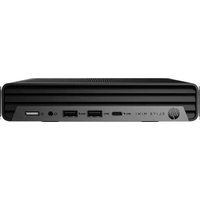


- Maintenance and Service Guide HP Pro SFF 400 G9 Desktop PC
- SUMMARY
- Legal information
- Product notice
- Software terms
- Table of contents
- Product features....1
- Illustrated parts catalog....4
- Routine care, drive guidelines, and disassembly preparation 12
- Removal and replacement procedures....22
- Troubleshooting without diagnostics....50
- POST error messages....88
- Password security and resetting CMOS....98
- Backing up, restoring, and recovering....100
- Statement of memory volatility....103
- Using HP PC Hardware Diagnostics 109
- Product features1
- Front panel components
- Rear panel components
- Serial number location
- Illustrated parts catalog2
- Computer major components
- Mass storage devices
- Cables
- Miscellaneous parts
- Routine care, drive guidelines, and disassembly preparation
- Electrostatic discharge information
- Generating static electricity
- Preventing electrostatic damage to equipment
- Personal grounding methods and equipment
- Grounding the work area
- Recommended materials and equipment
- Operating guidelines
- Routine care
- General cleaning safety precautions
- Removing dirt and debris from your computer
- Cleaning your computer with a disinfectant
- Cleaning the computer case
- Cleaning the keyboard
- Cleaning the monitor
- Cleaning the mouse
- Service considerations
- Tools and software requirements
- Screws
- Cables and connectors
- Hard drives
- Lithium coin cell battery
- SATA hard drives
- Cable management
- Removal and replacement procedures4
- Preparation for disassembly
- Access panel
- Battery
- ▲WARNING
- Optical drive
- Front bezel
- Speaker
- WLAN module
- Solid-state drive
- Memory modules (DIMMs)
- Expansion card
- Fan hood
- Option board
- Heat sink
- Processor
- Power supply
- System board
- Wireless antennas (select models only)
- Troubleshooting without diagnostics5
- Before you call for technical support
- Helpful hints
- Solving general problems
- Cannot access the Computer Setup (F10) Utility when booting the computer
- Computer appears locked up and will not turn off when the power button is pressed
- Computer will not respond to keyboard or mouse
- Computer date and time display is incorrect
- There is no sound or sound volume is too low
- Cannot remove computer cover or access panel
- Poor performance
- System does not turn on and the lights on the front of the computer are not blinking
- Solving power problems
- Power supply shuts down intermittently
- Solving hard drive problems
- Hard drive error occurs
- Disk drive transaction problem
- Drive not found (identified)
- Nonsystem disk/NTLDR missing message
- Computer will not boot from hard drive
- Computer seems to be locked up
- Solving audio problems
- Sound cuts in and out
- Sound does not come out of the speaker or headphones
- Computer appears to be locked up while recording audio
- Line-in jack is not functioning properly
- Solving printer problems
- Printer will not print
- Printer will not turn on
- Printer prints garbled information
- Solving keyboard and mouse problems
- Keyboard commands and typing are not recognized by the computer
- Mouse does not respond to movement or is too slow
- Solving hardware installation problems
- A new device is not recognized as part of the system
- Computer will not start
- Solving network problems
- Network driver does not detect network controller
- Network status link light never blinks
- Diagnostics reports a failure
- Diagnostics passes, but the computer does not communicate with the network
- Network controller stopped working when an expansion board was added to the computer
- Network controller stops working without apparent cause
- Cannot connect to network server when attempting remote system installation
- System setup utility reports unprogrammed EEPROM
- Solving memory problems
- System will not boot or does not function properly after installing additional memory modules
- Out of memory error
- Memory count during POST is wrong
- Insufficient memory error during operation.
- Solving USB flash drive problems
- USB flash drive is not seen as a drive letter in Windows
- USB flash drive not found (identified)
- System will not boot from USB flash drive
- The computer boots to DOS after making a bootable flash drive
- Solving internet access problems
- Unable to connect to the internet
- Cannot automatically launch internet programs
- Solving software problems
- Computer will not start up and the HP logo does not appear
- "Illegal Operation has Occurred" error message is displayed
- Computer Setup (F10) Utility6
- Using Computer Setup (F10) Utilities
- Computer Setup Main
- Computer Setup Security
- Computer Setup Advanced
- POST error messages7
- POST numeric codes and text messages
- Interpreting POST diagnostic front panel lights and audible codes
- Password security and resetting CMOS8
- Changing a setup or power-on password
- Deleting a setup or power-on password
- Backing up, restoring, and recovering9
- Backing up information and creating recovery media
- Using Windows tools for backing up
- Using the HP Cloud Recovery Download Tool to create recovery media (select products only)
- Restoring and recovering your system
- Creating a system restore
- Restoring and recovery methods
- Recovering using HP Recovery media
- Changing the computer boot order
- Using HP Sure Recover (select products only)
- Statement of memory volatility10
- Current BIOS steps
- Nonvolatile memory usage
- Questions and answers
- Using HP Sure Start (select products only)
- Using HP PC Hardware Diagnostics11
- Using HP PC Hardware Diagnostics Windows (select products only)
- Using an HP PC Hardware Diagnostics Windows hardware failure ID code
- Accessing HP PC Hardware Diagnostics Windows
- Accessing HP PC Hardware Diagnostics Windows from HP Support Assistant
- Accessing HP PC Hardware Diagnostics Windows from the Start menu (select products only)
- Downloading HP PC Hardware Diagnostics Windows
- Downloading the latest HP PC Hardware Diagnostics Windows version from HP
- Downloading the HP PC Hardware Diagnostics Windows from the Microsoft Store
- Installing HP PC Hardware Diagnostics Windows
- Using HP PC Hardware Diagnostics UEFI
- Using an HP PC Hardware Diagnostics UEFI hardware failure ID code
- Starting HP PC Hardware Diagnostics UEFI
- Starting HP PC Hardware Diagnostics UEFI through HP Hotkey Support software (select products only)
- Downloading HP PC Hardware Diagnostics UEFI to a USB flash drive
- Downloading the latest HP PC Hardware Diagnostics UEFI version
- Downloading HP PC Hardware Diagnostics UEFI by product name or number (select products only)
- Using Remote HP PC Hardware Diagnostics UEFI settings (select products only)
- Downloading Remote HP PC Hardware Diagnostics UEFI
- Downloading the latest Remote HP PC Hardware Diagnostics UEFI version
- Downloading Remote HP PC Hardware Diagnostics UEFI by product name or number
- Customizing Remote HP PC Hardware Diagnostics UEFI settings
- Power cord set requirements12
- General requirements
- Japanese power cord requirements
- Country-specific requirements
- Specifications13
- Index
- A
- B
- C
- D
- E
- F
- G
- H
- |
- K
- L
- M
- N
- O
- P
- R
- S
- T
Brand : HP
Model : Pro SFF 400 G9
Category : Computer