DF25A - Outboard motor SUZUKI - Free user manual and instructions
Find the device manual for free DF25A SUZUKI in PDF.


| Product Type | Outboard Motor |
| Brand | Suzuki |
| Model | DF25A |
| Engine Type | 4-Stroke |
| Power Output | 25 hp (18.6 kW) |
| Displacement | 498 cc |
| Number of Cylinders | 2 |
| Starting System | Electric Start |
| Steering | Tiller / Remote Control |
| Shaft Length | 20 inches (508 mm) |
| Weight | 57.6 kg (127 lbs) |
| Fuel System | Electronic Fuel Injection (EFI) |
| Ignition | Digital CDI |
| Cooling System | Water-Cooled |
| Gear Ratio | 2.08:1 |
| Propeller | Included (3-Blade) |
| Lubrication | Wet Sump |
| Recommended Oil | SAE 10W-40 |
| Emission Compliance | EPA / CARB Compliant |
| Maintenance | Easy Access Service Points |
Frequently Asked Questions - DF25A SUZUKI
User questions about DF25A SUZUKI
0 question about this device. Answer the ones you know or ask your own.
Ask a new question about this device
Download the instructions for your Outboard motor in PDF format for free! Find your manual DF25A - SUZUKI and take your electronic device back in hand. On this page are published all the documents necessary for the use of your device. DF25A by SUZUKI.
USER MANUAL DF25A SUZUKI
Please read this manual and follow its instructions carefully. To emphasize special information, the symbol ▲ and the words WARNING, CAUTION, NOTICE and NOTE have special meanings. Pay special attention to the messages highlighted by these signal words.
WARNING
Indicates a potential hazard that could result in death or serious injury.
CAUTION
Indicates a potential hazard that could result in minor or moderate injury.
NOTICE
Indicates a potential hazard that could result in damage to the motor or boat.
NOTE:
Indicates special information to make maintenance easier or instructions clearer.

This symbol appears in various locations on your Suzuki product to refer you to important information in the owner's manual.
IMPORTANT NOTICE TO OWNERS
WARNING
Failure to take the proper precautions may increase the risk of death or severe injury to you and your passengers.
- Prior to first-time use of your outboard motor, familiarize yourself thoroughly with the contents of this owner's manual. Be aware of all outboard motor features and all safety and maintenance requirements.
-
Inspect the boat and motor before each trip. See the INSPECTION BEFORE BOATING section for important items.
-
Become thoroughly familiar with all operating and handling characteristics of your boat and motor. Practice at low and moderate speeds until you are competent at handling the boat and motor. Do not attempt to operate at maximum performance until you are completely familiar with all of these characteristics.
- Carry boating safety and emergency equipment. This important equipment includes; flotation aids for each person (plus one throwable buoyant cushion in any boat 16 feet or longer), fire extinguisher, sound signaling device, visual distress signals, anchor, bilge pump, bucket, compass, emergency starter rope, extra fuel and oil, first aid kit, flashlight, food and water, mirror, paddles, tool kit, and transistor radio. Be sure you are carrying the equipment appropriate for your trip before launching.
- Never start the engine or let it run indoors or where there is little or no ventilation. Exhaust gas contains carbon monoxide, a gas that is colorless and odorless and can cause death or severe injury.
- Instruct your passengers on how to operate the boat, how to deal with emergencies, and how to operate safety and emergency equipment.
- Do not hold onto the motor cover or any other parts of your outboard motor while getting on or off your boat.
- Ensure that everyone wears a PFD (Personal Flotation Device) on board.
- Never operate the boat while under the influence of alcohol or other drugs.
- Distribute all weight load evenly in the boat.
- Have all scheduled maintenance performed. Consult your authorized Suzuki marine dealer as required.
- Do not modify or remove any outboard motor standard equipment. To do so may make the motor unsafe to use.
- Learn and obey all applicable navigation rules.
- Pay attention to all weather forecasts. Do not set out if weather is unsettled.
- Use extreme caution when purchasing replacement parts or accessories. Suzuki strongly recommends that you use only genuine Suzuki replacement parts/accessories or their equivalent. Inappropriate or poor quality replacement parts or accessories can create unsafe operating conditions.
- Never remove the flywheel cover (except for when emergency starting).
NOTE:
Mounting radio transceiver or navigational equipment antennae too close to the engine cowling can cause electrical noise interference. Suzuki recommends that antennae be mounted at least one meter (40 inches) away from the engine cowling.
This manual should be considered a permanent part of the outboard motor and should remain with the outboard motor when resold or otherwise transferred to a new owner or operator. Please read this manual carefully before operating your new Suzuki and review the manual from time to time. It contains important information on safety, operation, and maintenance.
FOREWORD
Thank you for choosing a Suzuki outboard motor. Please read this manual carefully and review it from time to time. It contains important information on safety, operation, and maintenance. A thorough understanding of the information presented in this manual will help you experience safe, enjoyable boating.
All information in this manual is based on the latest product information available at the time of publication. Due to improvements or other changes, there may be discrepancies between this manual and your outboard motor. Suzuki reserves the right to make changes at any time without notice.
TABLE OF CONTENTS
IDENTIFICATION NUMBER LOCATION.... 5
FUEL AND OIL.... 5
LOCATION OF SAFETY LABELS ..... 8
LOCATION OF PARTS...... 10
MOTOR MOUNTING...... 16
BATTERY INSTALLATION ...... 17
USE OF ELECTRICAL ACCESSORIES 19
PROPELLER SELECTION AND INSTALLATION.... 19
ADJUSTMENT...... 20
CAUTION SYSTEM 23
DIAGNOSTIC SYSTEM 26
OIL CHANGE REMINDER SYSTEM.... 27
ENGINE STALLING CAUTION SYSTEM.... 28
OPERATION OF TILTING SYSTEMS (DF25A/25AR/30A/30AR) . 29
OPERATION OF TILTING SYSTEMS (DF30AQ).... 32
OPERATION OF TILTING SYSTEMS (DF25AT/25ATH/30AT/30ATH) 33
INSPECTION BEFORE BOATING ... 35
BREAK-IN 37
OPERATION 38
MOTOR REMOVAL AND TRANSPORTING .... 51
TRAILERING.... 53
INSPECTION AND MAINTENANCE.... 54
FLUSHING THE WATER PASSAGES.... 63
SUBMERGED MOTOR 65
STORAGE PROCEDURE 66
AFTER STORAGE 67
TROUBLESHOOTING 67
SPECIFICATIONS 69
INFORMATION REGARDING EC - DIRECTIVE .... 69
FLOWCHART OF OIL CHANGE REMINDER SYSTEM.... 70
IDENTIFICATION NUMBER LOCATION
The model and identification numbers of your outboard motor are stamped on a plate attached to the clamp bracket. It is important to know these numbers when you place a parts order or if your motor is stolen.

FUEL AND OIL
GASOLINE
Suzuki highly recommends that you use alcohol-free unleaded gasoline whenever possible, with a minimum octane rating of 91 (Research method). However, blends of unleaded gasoline and alcohol with equivalent octane content may be used, provided the guidelines that follow are met.
NOTICE
Use of leaded gasoline can cause engine damage. Use of improper or poor quality fuel can affect performance and may damage your motor and fuel system.
Use only unleaded gasoline. Do not use fuel having lower than the recommended octane, or fuel that may be stale or contaminated by dirt/water etc.
NOTE:
Oxygenated fuels are fuels which contain oxygen-carrying additives such as alcohol.
Suzuki recommends that you install a water-separating fuel filter assembly between your boat's fuel tank(s) and outboard motor(s). Fuel filtration systems of this type will help prevent water that may be present in your boat's fuel tank(s) from contaminating your motor's electronic fuel injection system. Water contamination can cause poor engine performance and can also cause damage to the electronic fuel injection system components.
Your Authorized Suzuki Marine Dealer can provide you advice about water-separating fuel filter systems and installation.
Gasoline/Ethanol Blends
Blends of unleaded gasoline and ethanol (grain alcohol), also known as “GASOHOL”, are commercially available in some areas. Blends of this type may be used in your outboard motor if they are no more than 10% ethanol. Make sure this gasoline-ethanol blend has octane ratings no lower than those recommended for gasoline.
Use the recommended gasoline which conforms to the following labels.

78RB0900*
Pump Labeling for Gasoline/Alcohol Blends
In some states, pumps that dispense gasoline/ alcohol blends are required to be labeled for the type and percentage of alcohol content, and whether important additives are present. Such labels may provide enough information for you to determine if a particular blend of fuel meets the requirements listed above. In other states, pumps may not be clearly labeled as to the content or type of alcohol and additives. If you are not sure that the fuel you intend to use meets these requirements, check with the service station operator or the fuel suppliers.
NOTE:
If you are not satisfied with the operation or fuel economy of your outboard motor when you are using gasoline/alcohol blends, you should switch back to unleaded gasoline containing no alcohol.
Be sure that any gasoline/alcohol blend you use has octane ratings of at least 91 octane (Research method).
If engine pinging is experienced, substitute another brand as there are differences between brands.
Unleaded gasoline will extend spark plug life.
WARNING
Gasoline is extremely flammable and toxic. It can cause a fire and can be hazardous to people and pets.
Always take the following precautions when refueling:
- Never permit anyone other than an adult to refill the fuel tank.
- If you use a portable fuel tank, always stop the motor and remove the fuel tank from the boat to refill it.
- Do not fill the fuel tank all the way to the top or fuel may overflow when it expands due to heating by the sun.
- Be careful not to spill fuel. If you do, wipe it up immediately.
- Do not smoke, and keep away from open flames and sparks.
NOTICE
Gasoline kept in the fuel tank for long periods of time will produce varnish and gum, which can damage the engine.
Always use fresh gasoline.
NOTICE
Fuels containing alcohol can cause paint damage, which is not covered under the New Outboard Motor Limited Warranty.
Be careful not to spill fuel containing alcohol while refueling. If fuel is spilled, wipe it up immediately.
NOTE:
The fuel tank supplied with this motor is its dedicated fuel reservoir and should not be used as a fuel storage container.
ENGINE OIL
NOTICE
Use of poor quality engine oil can adversely affect engine performance and life.
Suzuki recommends that you use Suzuki Marine 4-Cycle Engine Oil or its equivalent.
Oil quality is a major contributor to your engine's performance and life. Always select good quality engine oil.
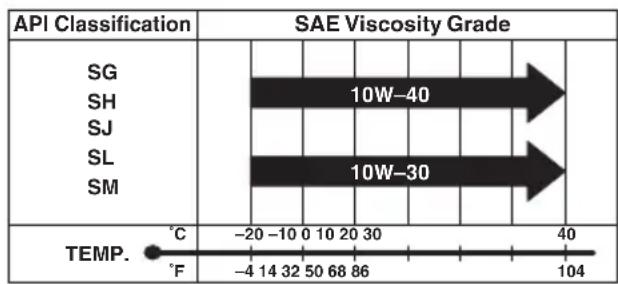
Suzuki recommends the use of SAE 10W-40 or 10W-30 SUZUKI MARINE 4-CYCLE ENGINE OIL. If SUZUKI MARINE 4-CYCLE ENGINE OIL is not available, select a NMMA certified FC-W oil or good quality 4-cycle motor oil from the following chart according to the average temperatures in your area.
NOTE:
In very cold weather (below 5° C ( 41° F)), use SAE (or NMMA FC-W) 5W-30 for easier starting and smooth operation.
GEAR OIL

Suzuki recommends the use of SUZUKI OUTBOARD MOTOR GEAR OIL. If it is not available, use SAE 90 hypoid gear oil which is rated GL-5 under the API classification system.
Read and follow all of the labels on your outboard motor or fuel tank. Make sure you understand all of the labels.
Keep the labels on your outboard motor or fuel tank. Do not remove them for any reason.

All models except for EU
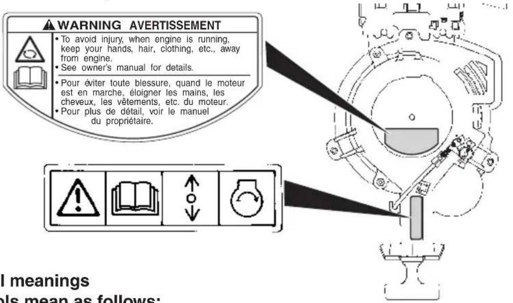
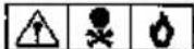
Label symbol meanings These symbols mean as follows;

: General warning symbol (Caution or Warning)

: Read owner's manual carefully

: Remote control lever/gear shift lever operation-two direction; Forward/Neutral/Reverse

: Engine start

: Hazard caused by fire

: Hazard caused by laying the motor on its side

: Hazard caused by rotating parts

GASOLINE

LISTED
PORTABLE WARMS
91 B2
EXTREMELY FLAMMABLE
FOR USE AS A MOTOR FUEL ONLY - MAY CONTAIN LEAD ANTI-INDEX COMPOUNDS
DANGER
HARMFUL OR FATAL IF SWALLOWED, KEEP OUT OF REACH OF CHOLIEM. IF SWALLOWED, DO NOT INDUCE VOTING, CALL A PHYSICIAN IMMEDIATELY.
CAUTION
KEEP TOTALLY CLOSED WHEN NOT IN USE, KEEP AWAY FROM MEAT, SPARKS, AND OPEN PLANE. SECURE ABOVE DECK IN WELL VENTILATED AREA DO NOT USE FOR LONG TINH FUEL STORAGE, FUEL/OIL KUCTURE FOLLOW MOTOR MANUFACTURERS RECOMMENDATIONS.
GASOLINE
EXTREMELY FLAMMABLE
REMOVE FROM BOAT FOR FILLING
GASOLINA
PELIGRD FLAMABLE
QUITARJO BEL PARCO PARA POWER GAS
LOCATION OF PARTS
TILLER HANDLE MODEL (DF25A/30A)


TILLER HANDLE MODEL (DF30AQ)

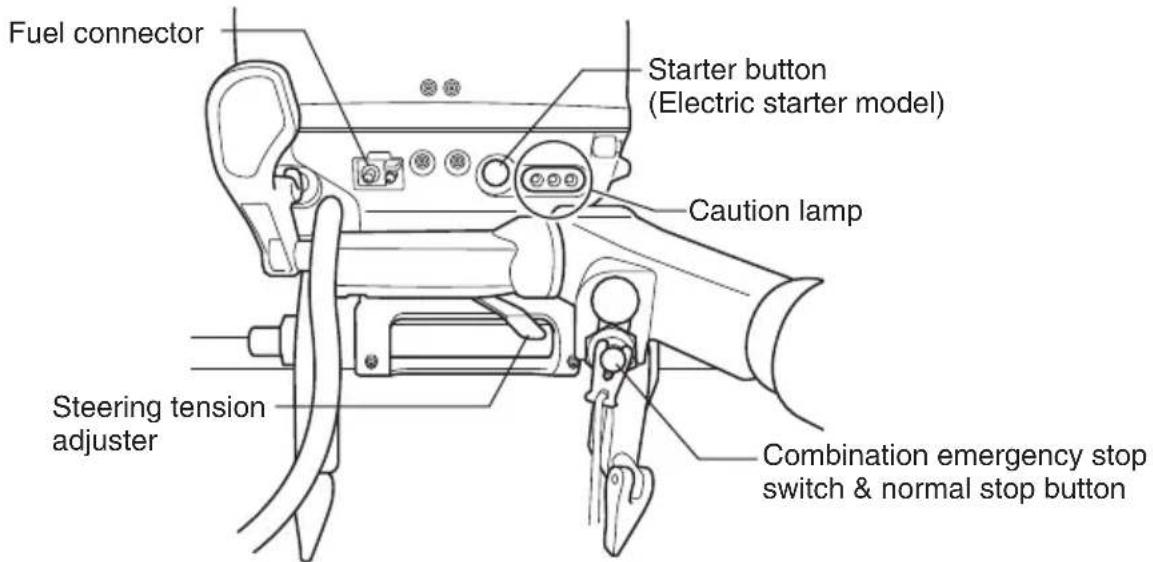
TILLER HANDLE MODEL (DF25ATH/30ATH)


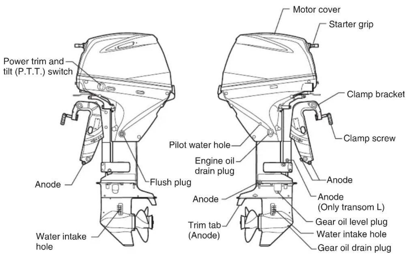
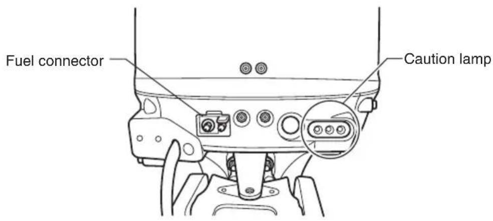

REMOTE CONTROL BOX (DF25AR/25AT/30AR/30AT)
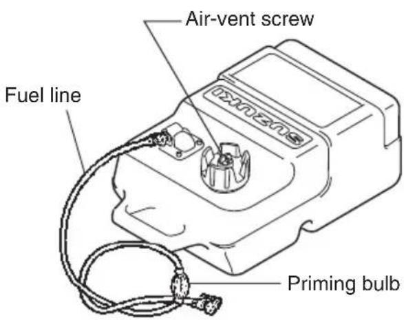
FUEL TANK (All models)
MOTOR MOUNTING
WARNING
Overpowering your boat can be hazardous. Excessive horsepower will have an adverse effect on hull safety and may cause operating/handling difficulties. The boat may also sustain stress and hull damage.
Never install an outboard motor with horsepower exceeding the manufacturer's recommended maximum horsepower listed on the boat's "Certification Plate". Contact your authorized Suzuki marine dealer if you are unable to locate the hull "Certificate Plate".
TILLER HANDLE MODEL
Proper transom height is important for good performance. A motor mounted on a transom that is too high causes the propeller to slip resulting in wasted power or overheating. A motor mounted on a transom that is too low will increase drag, causing reduced speed.
Make sure that when the motor is lowered all the way down, the anti-cavitation plate is located 0 – 25 mm (0 – 1.0 in) below the bottom of the boat.

NOTICE
Operating your outboard motor with the anti-cavitation plate above water can cause overheating and severe damage to your outboard motor.
Do not operate your outboard motor with the anti-cavitation plate above water.
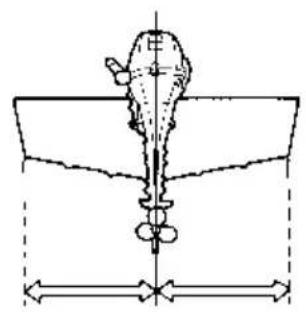
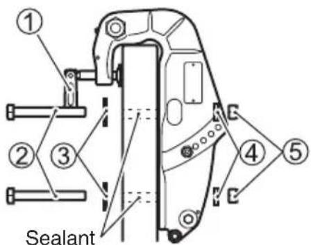
Center the motor on the transom and secure it by alternately tightening the clamp screws ① by hand. Make sure you accurately center the motor, or the boat will pull to one side during operation.
Install the bolts ②, washers ③, washers ④ and nuts ⑤, as illustrated and tighten the bolts sequentially. Be sure to seal the holes with sealant to prevent water leakage.

NOTICE
If you attempt to mount the outboard to the transom without having mechanical experience or without being certain where to drill holes, you can seriously damage the boat.
If you do not have mechanical experience or are not sure of where to drill holes in the boat's transom, you should have your motor mounted by your authorized Suzuki marine dealer.
After installing the motor, check to make sure that steering and tilt movement are not obstructed by any part of the boat. Also make sure that the battery cable (if provided) doesn't interfere with movement of the motor.
WARNING
If the motor is not properly secured to the transom, it can come off.
Be sure to bolt the motor to the transom. The motor may come off if it is held only by the clamp screws. Occasionally check the clamp screws for tightness.
REMOTE CONTROL MODEL
Suzuki strongly recommends that you have your outboard motor, controls and gauges installed by an authorized Suzuki Marine Dealer. He has the tools, the facilities and the know-how.
WARNING
Failure to have your outboard motor and associated controls and gauges properly installed can result in personal injury or damage.
Suzuki strongly recommends that you have your outboard motor, controls and gauges installed by your authorized Suzuki marine dealer. He has the tools, the facilities, and the know-how to do the job correctly.
BATTERY INSTALLATION
BATTERY REQUIREMENT ELECTRIC STARTER MODEL
650 Marine Cranking Amps (MCA)/ABYC, or 512 Cold Cranking Amps (CCA)/SAE or 160 Reserve Capacity (RC) Minutes/SAE or 12 Volt, 70 AH
NOTE:
- The specifications listed above are the minimum battery rating requirements for starting the engine.
• Additional electrical loads from the boat will require larger capacity batteries. Consult your Suzuki dealer to determine the proper battery sizing for your boat and engine combination. - Dual-purpose (Cranking/Deep-cycle) batteries can be used if they meet the minimum specifications listed above (MCA, CCA, or RC).
- Do not use a Deep Cycle battery for the main cranking battery.
- When connecting batteries in parallel, they must be of the same type, capacity, manufacturer, and of similar age. When replacement is necessary, they should be replaced as a set. Consult your Suzuki dealer for proper battery installation information.
BATTERY INSTALLATION
Secure the battery in a dry area of the boat, away from vibration.
NOTE:
- It is recommended that the battery be installed in an enclosed battery case.
- When connecting batteries, hexagon-nuts must be used to secure battery leads to battery posts.
To hook up the battery, first connect the red lead from the motor to the positive battery terminal, then connect the black lead to the negative battery terminal.

To remove the battery, first disconnect the black lead from the negative terminal, then disconnect the red lead from the positive terminal.
Suzuki recommends that you install the terminal cap on the positive battery terminal to prevent an accidental short circuit of battery terminals.
If a terminal cap is required, contact your authorized Suzuki marine dealer.
WARNING
If you place the battery near the fuel tank, a spark from the battery may ignite the gasoline, causing a fire and/or an explosion.
Do not place the fuel tank in the same compartment/area as the battery.
WARNING
Batteries produce flammable hydrogen gas and may explode if they are near flames or sparks.
Never smoke or cause sparks when working near the battery. Keep the battery away from open flames. To avoid creating a spark when charging the battery, connect the battery charger cables to the proper terminals before turning the charger on.
WARNING
Battery acid is poisonous and corrosive. It can cause severe injury and can damage painted surfaces.
Avoid contact with eyes, skin, clothing, and painted surfaces. If battery acid comes in contact with any of these, flush immediately with large amounts of water. If acid contacts the eyes or skin, get immediate medical attention.
NOTICE
The electrical system or its components may be damaged if proper battery precautions are not followed.
- Be sure to attach battery leads correctly.
- Do not disconnect battery leads from the battery while the engine is running.
USE OF ELECTRICAL ACCESSORIES
To use electrical accessories, you must purchase a 70 AH or larger battery, rectifier and related items. (Recoil starter model only).
NOTICE
If you connect electrical accessories directly to the power receptacle of the motor, the electrical accessories could be damaged.
Connect lights and electrical accessories for the boat to the battery. Consult your authorized Suzuki marine dealer for information about correct wiring.
The amount of power (DC12V) available for accessories, however, depends on the operating condition of the motor. For getting a detailed information, please inquire of your authorized Suzuki Marine Dealer.
NOTE:
Use of too much power for electrical accessories under certain operating conditions can cause the battery to discharge.
NOTE:
On the models equipped with a receptacle, detach the charging cord from the receptacle and fit the cap to prevent water entry when not using power supply.
PROPELLER SELECTION AND INSTALLATION
PROPELLER SELECTION
It is essential to use a propeller on your outboard motor that is properly matched to your boat's operating characteristics. The speed of the engine when you operate your boat at full throttle depends on the propeller you use.
Excessive engine speed can seriously damage the motor, while low engine speed at full throttle will adversely affect performance. Your operating load will also affect propeller selection. Smaller loads generally require larger-pitch propellers; larger loads generally require smaller-pitch propellers. Your authorized Suzuki Marine Dealer will assist you in selecting a suitable propeller for your boat.
NOTICE
Installing a propeller with either too much or too little pitch will cause incorrect maximum engine speed, which may result in severe damage to the motor.
Ask your authorized Suzuki marine dealer to assist you in selecting a suitable propeller for your boat.
You can determine if your propeller is appropriate for use with your boat by using a tachometer to measure engine speed when operating your boat at full throttle, under minimum load conditions. If you are using an appropriate propeller, the engine speed will be within the following range:
| Full throttle operating range | DF25A | 5000 – 6000 r/min. (min -1 ) |
| DF30A | 5300 – 6300 r/min. (min -1 ) |
If the engine speed is not within this range, consult your authorized Suzuki Marine Dealer to determine which propeller size is best for you.
PROPELLER INSTALLATION
WARNING
Failure to take proper precautions when installing or removing the propeller can result in severe personal injury.
When installing or removing the propeller:
- Always shift into "Neutral" and remove the emergency stop switch lock plate so that the motor cannot be started accidentally.
- Wear gloves to protect hands, and "lock" the propeller by placing a block of wood between the blades and the anti-cavitation plate.
To install a propeller on your outboard motor, use the following procedure:
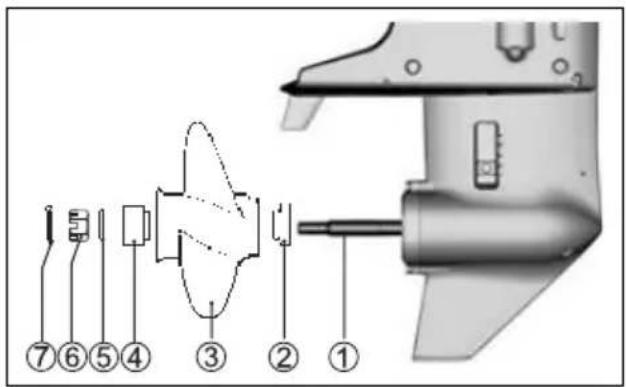
- Coat the propeller shaft splines ① liberally with Suzuki water resistant grease to help prevent corrosion.
- Place the stopper ② on the shaft.
- Align the propeller ③ with the propeller shaft splines and slide the propeller onto the shaft.
- Place the spacer ④ and washer ⑤ on the shaft.
- Install the propeller nut ⑥ and tighten it with a torque wrench to 20 - 30 N·m (2.0 - 3.0 kg·m/14.5 - 21.5 lb·ft).
- Align the grooves in the propeller nut with the hole in the shaft, then insert the cotter pin ⑦ and bend the pin ends over to lock it in place.
To remove the propeller, reverse the above procedure.
ADJUSTMENT
TRIM ANGLE ADJUSTMENT
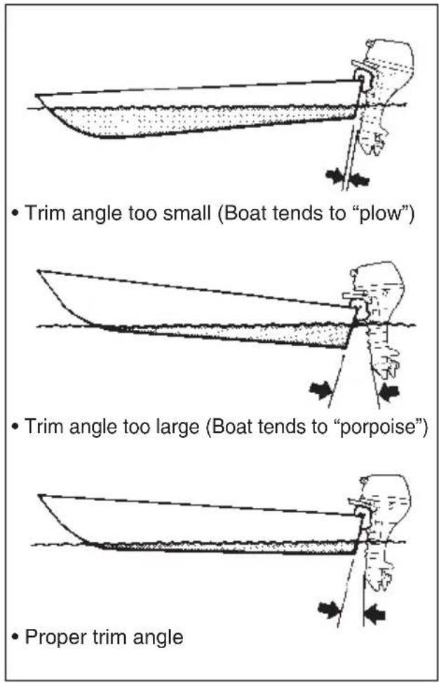
To help maintain steering stability and good performance, always maintain the proper trim angle as shown in the illustration. The appropriate trim angle varies depending on the combination of the boat, engine, and propeller, as well as operating conditions.
DF25A/25AR/30A/30AR
Make a test run in the boat to determine if the trim angle needs to be adjusted.
To adjust the trim angle:
- Hold the motor in the fully tilted up position. (Refer to TILT UP LOCK ARM section.)
- Reposition the tilt pin Ⓐ in the desired holes.

- Lower the motor back down.
To lower the bow, move the pin towards the boat. To raise the bow, move the pin away from the boat.
DF30AQ
Make a test run in the boat to determine if the trim angle needs to be adjusted.
To adjust the trim angle:
- Lock the motor in the fully tilted up position. (Refer to TILT LOCK LEVER section.)
- Loosen the nuts Ⓑ securing tilt pin Ⓐ. Reposition the tilt pin Ⓐ in the desired holes, then tighten the nuts securely.

- Lower the motor back down.
To lower the bow, move the pin towards the boat. To raise the bow, move the pin away from the boat.
WARNING
Trim angle greatly affects steering stability. If the trim angle is too small, the boat may "plow" or "bow steer". If the trim angle is too large, the boat may "chine walk" from side to side or "porpoise" up and down. These conditions, which result in loss of steering control, can cause occupants to be thrown overboard.
Always maintain proper trim angle based on the combination of your boat, engine, and propeller, as well as operating conditions.
WARNING
If you operate the motor with the tilt pin removed, you may not be able to control steering as expected.
Do not operate the motor with the tilt pin removed.
DF25AT/25ATH/30AT/30ATH
Make a test run in the boat to determine if the trim angle needs to be adjusted. Adjust the trim angle using the Power Trim and Tilt system. Refer to the POWER TRIM AND TILT section.
If you still cannot achieve good performance, there may be a problem with engine mounting height. Consult your dealer for assistance.
WARNING
Trim angle greatly affects steering stability. If the trim angle is too small, the boat may "plow" or "bow steer". If the trim angle is too large, the boat may "chine walk" from side to side or "porpoise" up and down. These conditions, which result in loss of steering control, can cause occupants to be thrown overboard.
Always maintain proper trim angle based on the combination of your boat, engine, and propeller, as well as operating conditions.
NOTICE
If you operate the boat with the motor trimmed beyond the maximum trim position, the water intake holes may be above the water line, causing severe engine damage due to overheating.
Never operate the boat with the motor trimmed beyond the maximum trim position.
TRIM TAB ADJUSTMENT
This adjustment is used to compensate for the possible tendency of your boat to veer slightly to port or starboard. This tendency could be due to such things as propeller torque, motor mounting position, etc.
To adjust the trim tab:
- Loosen the bolt Ⓐ that holds the trim tab in place.

- If the boat tends to veer to port, move the rear end of the trim tab toward the port side. If the boat tends to veer to starboard, move the starboard side.

- Tighten the bolt that holds the trim tab in place.
After adjusting the trim tab, check to see if the boat still tends to veer to one side. If necessary, readjust the trim tab.
STEERING TENSION ADJUSTMENT
The steering on your outboard motor should be smooth and not tight. Adjust the steering tension so that there is only a slight resistance to steering movement.
TILLER HANDLE MODEL
To increase the steering tension, move the lever Ⓐ to the left. To decrease the steering tension, move the lever to the right.

NOTE:
Do not apply a grease to the area Ⓑ.
THROTTLE TENSION ADJUSTMENT TILLER HANDLE MODEL
The tension of the throttle control grip can be adjusted according to your preference. To increase the tension, turn the throttle tension adjuster Ⓐ clockwise. To decrease the tension, turn the adjuster counterclockwise.

REMOTE CONTROL MODEL
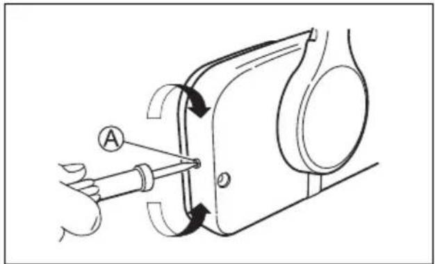
The tension of the remote control handle can be adjusted according to your preference. To increase the tension, turn the throttle tension adjuster Ⓐ clockwise. To decrease the tension, turn the adjuster counterclockwise.
IDLE SPEED ADJUSTMENT
The idle speed has been factory adjusted between 800 – 900 r/min. in neutral.
NOTE:
If idle speed cannot be set within the specified range, contact your authorized Suzuki Marine Dealer.
CAUTION SYSTEM
The caution systems are designed to alert you to certain situations which may cause damage to your outboard motor.
NOTICE
Your outboard motor may become damaged if you rely on the Caution System to alert you to any malfunction that may occur or to give you an indication of the need for maintenance.
To avoid damage to your outboard motor, regularly inspect and maintain it.
NOTICE
Continuing to operate your outboard motor with the Caution System activated can result in severe damage to your outboard motor.
If the Caution System activates while you are operating your outboard motor, stop the motor as soon as possible and correct the problem or consult your authorized Suzuki marine dealer for assistance.
CAUTION LAMP CHECK
TILLER HANDLE MODEL
Each time the starter system is operated, the three caution lamps – the TEMP ①, the OIL ② and the CHECK ENGINE ③ will light briefly for the first two seconds, regardless of the motor condition.

NOTICE
If the Caution System is not working properly, you may not be alerted to a condition that could cause damage to your outboard motor.
If the caution lamp does not come on briefly once the starter system is operated, the caution lamp may be broken or a failure may exist in the system circuit. Consult your authorized Suzuki marine dealer.
REMOTE CONTROL MODEL
Each time the ignition key is turned to the "ON" position, the three caution lamps – the TEMP ①, the OIL ② and the CHECK ENGINE ③ will light briefly for the first two seconds and the buzzer in the remote control box will also sound.

NOTICE
If the Caution System is not working properly, you may not be alerted to a condition that can cause damage to your outboard motor.
If the caution lamp does not come on or the buzzer does not sound when the ignition key is turned on, the caution lamp or buzzer may be broken or a failure may exist in the system circuit. Consult your authorized Suzuki marine dealer.
NOTICE
Continuing to operate your outboard motor with the Oil pressure Caution System activated can result in severe damage to your outboard motor.
If the Oil Pressure Caution System activates, stop the engine as soon as possible and add oil if necessary. If the oil level is correct, consult your authorized Suzuki marine dealer.
OVER-REVOLUTION CAUTION SYSTEM
This system is activated when engine speed exceeds the maximum recommended speed for more than 10 seconds.
If this system activates, engine speed will automatically be reduced to approximately 3000 r/min.
On the remote control model, the buzzer in the remote control box will simultaneously begin a series of beeps.
This system must be reset by moving the throttle to the idle position for about four seconds to restore full engine operation.
NOTE:
The red Caution lamp does not light when the over-revolution caution system activates.
NOTICE
If the Over-Revolution Caution System activates at recommended maximum throttle and you are sure that the propeller pitch is sufficient and there are no factors like “over-trimming” or “ventilation”, there may be a problem with the Over-Revolution Caution System.
Consult your authorized Suzuki marine dealer if the Over-Revolution Caution System activates for no apparent reason.
OIL PRESSURE CAUTION SYSTEM
This system operates when the engine lubricating oil pressure drops below the correct pressure.
If this system activates, the red OIL lamp will light. On the remote control model, the buzzer in the remote control box will simultaneously begin a series of beeps. When this system is activated at 1000 r/min. or higher, engine speed will automatically be reduced to approximately 1000 r/min.

If you continue to run, the engine will automatically stop 3 minutes after beginning of the above CAUTION system activation.
NOTE:
In case that the engine is automatically stopped due to the CAUTION system, the engine can be started again.
However the CAUTION system will repeatedly activate until eliminating the cause.
If this system activates, stop the engine immediately, if wind and water conditions make it safe to do so.
WARNING
If you attempt to remove or reinstall the motor cover while the engine is running, you may be injured.
To check the oil level, stop the engine and then remove the motor cover.
Check the oil level and add oil if necessary. If the oil level is correct, consult your authorized Suzuki Marine Dealer.
NOTICE
Your engine may become severely damaged if you rely on the Oil Pressure Caution System to indicate the need to add engine oil.
Check the engine oil level periodically and add oil as necessary.
NOTICE
Operating the engine with the Oil Pressure Caution System activated can result in severe engine damage.
If the Oil Pressure Caution System activates, stop the engine as soon as possible and add engine oil, if necessary, or otherwise correct the problem.
OVERHEAT CAUTION SYSTEM
This system is activated when the cylinder wall temperature is too high due to insufficient water cooling.
If this system activates, the red TEMP lamp will light. On the remote control model, the buzzer in the remote control box will simultaneously begin a series of beeps. When this system is activated at 3000 r/min. or higher, engine speed will automatically be reduced to approximately 3000 r/min.

If you continue to run, the engine will automatically stop 3 minutes after beginning of the above CAUTION system activation.
NOTE:
In case that the engine is automatically stopped due to the CAUTION system, the engine can be started again.
However the CAUTION system will repeatedly activate until eliminating the cause.
If the overheat caution system activates when operating, reduce engine speed immediately and check to see if water is being discharged from the pilot water hole. If no water is seen, follow the procedures outlined below.
Water and wind conditions permitting, stop the motor, tilt it out of the water and remove any debris like seaweed, plastic bags or sand that may have blocked the water intakes.
Lower the motor into the water, being sure that water intakes are immersed, and restart it.
Check (A) that water discharges from the pilot hole and (B) that the red TEMP lamp is no longer lit.
Be aware that the red TEMP lamp may light again if engine temperature rises abnormally. If either of the above situations arises, your authorized Suzuki Marine Dealer must be consulted as soon as possible.
NOTICE
Operating the engine with the overheat caution system activated can result in severe engine damage.
If the overheat caution system activates, stop the engine as soon as possible, wind and water conditions permitting, and inspect the engine according to the above instructions. Consult your authorized Suzuki marine dealer if you cannot correct the problem.
DIAGNOSTIC SYSTEM
If abnormal conditions exist in any sensor signal being input to the control unit, the self-diagnostic system warns of the abnormal condition.
TILLER HANDLE MODEL
If this system activates, the CHECK ENGINE lamp will flash.
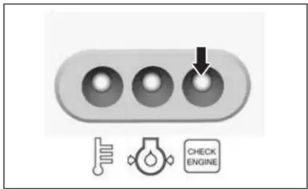
Also incorporated is a fail-safe provision that allows the operation at a restricted speed even under such a failure condition.
The failed system can be identified by the mode of the CHECK ENGINE lamp flashing.
The diagnostic code is designed to appear when the engine is running.
REMOTE CONTROL MODEL
When engine is running.
If this system activates, the CHECK ENGINE lamp will flash and a buzzer will sound.
Ignition key is turned to the "ON" position, when engine is not running.
If this system activates, the CHECK ENGINE lamp will flash.
Also incorporated is a fail-safe provision that allows the operation at a restricted speed even under such a failure condition.
The failed system can be identified by the mode of the CHECK ENGINE lamp flashing.
This diagnostic code is designed to appear while the ignition key is turned on.
The buzzer sound with diagnostic system activating will be stopped after approx. thirty seconds.
NOTICE
If the diagnostic system activates while you are operating your outboard motor, there is an abnormal condition in one of the sensor signals of the control system.
Consult your authorized Suzuki marine dealer for repair of the control system.
OIL CHANGE REMINDER SYSTEM
This system informs the operator of the time for replacing engine oil on the basis of the maintenance schedule.
The system is designed to register the total operating hours of the outboard motor and function its operation when the preprogrammed hours have reached.
(Refer to the INSPECTION AND MAINTENANCE section and the last page.)
SYSTEM ACTIVATION
TILLER HANDLE MODEL
When the total operating hours have reached the preprogrammed hours, the red OIL lamp will flash while the engine is running. This indication will repeat until you cancel the system activation.
REMOTE CONTROL MODEL
When the total operating hours have reached the preprogrammed hours, the red OIL lamp will flash and a buzzer will sound. This OIL lamp indication will repeat until you cancel the system activation.
The buzzer sound will be stopped after approx. thirty seconds.
NOTE:
Ignition key is turned to the "ON" position while engine is not running.
This system activates, the red OIL lamp will flash but no buzzer sound. This OIL lamp indication will repeat until you cancel the system activation.
CANCELLATION
TILLER HANDLE MODEL
- Start the motor.
Make sure that the motor is in "NEUTRAL" and the throttle grip is fully closed.
NOTE:
The engine stops when the engine stop button is kept to push more than 0.5 seconds.
- Push the engine stop button ① three times within three seconds so that the engine should not stall.
The red OIL lamp is no longer lit when the reminder cancellation is successful.
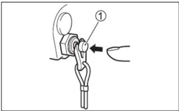
- Stop the engine.
CANCELLATION
REMOTE CONTROL MODEL
- Shift into "NEUTRAL".
- Turn the ignition key to the "ON" position.
- Pull out the emergency stop switch plate ①.
- Pull up the emergency stop switch knob ② three times within 4 seconds. The red OIL lamp is no longer lit when the reminder cancellation is successful. A short beep will be heard if the cancellation is successfully finished.
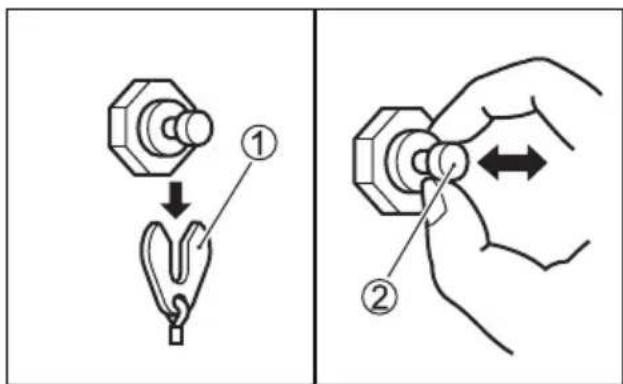
- Turn the ignition key to the "OFF" position.
- Set the plate ① in the original position.
NOTE:
- Canceling of the system activation is possible regardless of whether or not the engine oil has been replaced. Once the system has operated, however, Suzuki strongly recommends that the engine oil be replaced before canceling the system activation.
- Even if the engine oil has been replaced with the system not operating, it is still necessary to perform the cancellation.
ENGINE STALLING CAUTION SYSTEM
REMOTE CONTROL MODEL
This system informs the operator when the motor stalls while it is operating. When the engine stalls for any reason, the caution buzzer sounds three times.
The release lever Ⓐ has two positions.
"Lock" Position
Use this position whenever you operate the motor in "REVERSE" gear and whenever you operate the motor in deep water where you do not expect to encounter underwater objects. Placing the release lever in the "lock" position prevents the motor from lifting out of the water due to forces such as propeller thrust during operation in "REVERSE" gear or rapid deceleration.

NOTICE
If you strike an underwater object with the release lever in the "LOCK" position, your outboard motor or boat may be damaged.
When operating the motor in an area where you may encounter underwater objects, move the release lever to the "RELEASE" position and operate the motor only at very low speeds.
"Release" Position
Use this position whenever you operate the motor in "FORWARD" gear in shallow water. Placing the release lever in the "release" position allows the motor to tilt up if you strike an underwater object, reducing the chance of damage to the motor. Refer to the OPERATION IN SHALLOW WATER section for details on shallow water operation.

WARNING
When you operate the motor with the release lever in the "Release" position, the tilt lock will not work. As a result, forces such as from propeller thrust during operation in "REVERSE" gear, rapid deceleration, and striking an underwater object can cause the motor to lift out of the water, resulting in personal injury.
When using the "Release" position, proceed with caution and only at very low speed.
TILT UP LOCK ARM
The tilt up lock arm is used to hold the motor in the fully tilted up position. To hold the motor in the fully raised position:
WARNING
If you place your hands near the mounting bracket or under the motor when tilting it, your hands can be crushed if the motor slips from your grasp.
Never place your hands near the mounting bracket or under the motor when tilting it.
- Shift into "NEUTRAL".
- Move the release lever ① to the "release" position.

- Grab the handle on the back of the motor cover and tilt the motor all the way up until it is automatically locked in the fully tilted up position by the tilt up lock arm ②.

NOTICE
If you use the throttle grip handle to raise or lower the motor, the handle may break.
Never use the throttle grip handle to raise or lower the motor.
To lower the motor back down:
- Move the release lever ① to the lock position.

- Pull the motor slightly towards you and slowly let the motor down.

WARNING
If you do not take proper precautions when tilting up the motor, fuel may leak out.
Disconnect the fuel line whenever you leave the motor tilted up for a long period of time.
NOTICE
If you use the tilt up lock arm to hold the motor in the fully tilted position for trailering, the tilt up lock arm could release resulting in damage to the motor.
When trailering your boat, never use the tilt up lock arm to hold the motor in the fully tilted position.
SHALLOW WATER POSITION
To set the shallow water position:
- Shift into "NEUTRAL".
- Move the release lever ① to the release position.

- Slowly tilt the motor up until you hear it make a "click" sound.

- Slowly lower the motor. It will stop in a position that is slightly tilted up from the normal trim angle.
NOTE:
There are two shallow water positions. Use whichever one is appropriate, depending on the depth of the water.
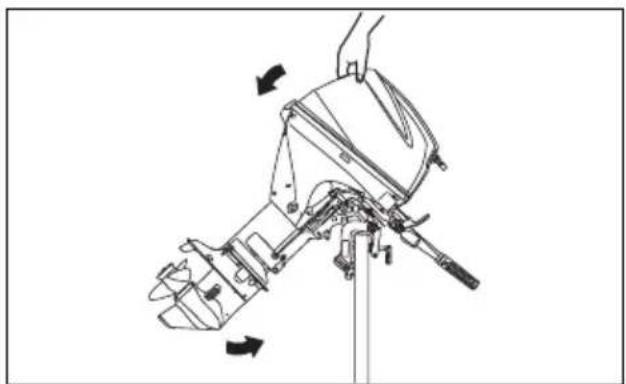
To lower the motor back down:
- Move the release lever ① to the lock position.
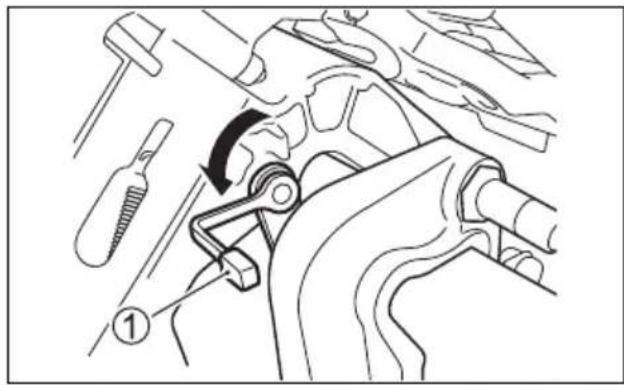
- Pull the motor slightly towards you and slowly let the motor down.

WARNING
When the shallow water position is used, the tilt lock will not work. As a result, forces such as from propeller thrust during operation in "REVERSE" gear, rapid deceleration, and striking an underwater object can cause the motor to lift out of the water, resulting in personal injury.
When using the shallow water position, proceed with caution and only at very low speeds.
The tilt lock lever is provided so you can support the motor in a tilted position for non-moving engine support.

WARNING
If you place your hands near the mounting bracket or under the motor when tilting it, your hands can be crushed if the motor slips from your grasp.
Never place your hands near the mounting bracket or under the motor when tilting it.
To hold the motor in the fully raised position:
- Shift into "NEUTRAL".
- Move the release lever ① to the "release" position.
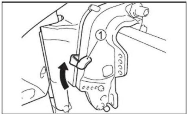
- Grab the handle on the back of the motor cover and tilt the motor all the way up.
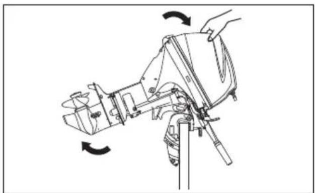
NOTICE
If you use the throttle grip handle to raise or lower the motor, the handle may break.
Never use the throttle grip handle to raise or lower the motor.
NOTICE
If the tiller handle contacts any objects when tilting motor up, the outboard motor or boat could be damaged.
When tilting the motor up, position the motor so the tiller handle will not contact such as a tackle box, ice chest, or the motor well.
- Pull down the tilt lock lever ②.
Lower the motor until the tilt lock lever touches the tilt stopper bolt ③.
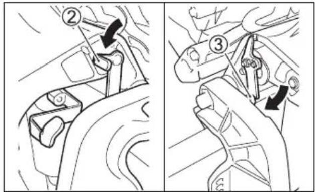
- Move the release lever ① to the lock position.
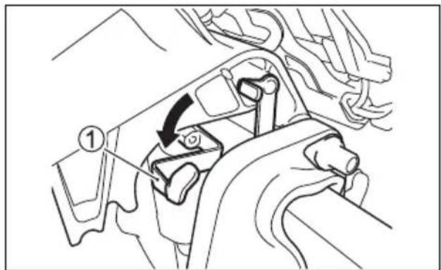
To lower the motor:
- Move the release lever ① to the release position.
- Pull the motor slightly towards you and pull up the tilt lock lever ②.
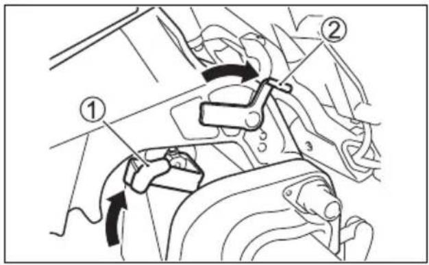
- Lower the motor by pushing the motor cover down.
- Move the release lever ① to the "lock" position.
WARNING
If you do not take proper precautions when tilting up the motor, fuel may leak out.
Disconnect the fuel line whenever you leave the motor tilted up for a long period of time.
NOTICE
If you use the tilt lock lever to hold the motor in the fully tilted position for trailering, the tilt lock lever could release resulting in damage to the motor.
When trailering your boat, never use the tilt lock lever to hold the motor in the fully tilted position.
The "Power Trim and Tilt" is operated by pressing the switch. To tilt the motor up, press the upper (right) part of the switch. To tilt the motor down, press the lower (left) part of the switch.
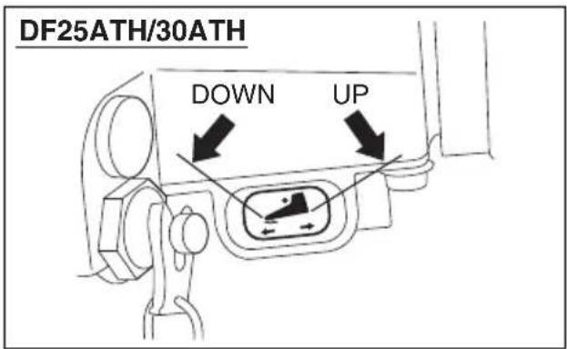
The power trim and tilt (PTT) switch can be accidentally activated when the ignition key is off, resulting in injury.
Keep all persons away from the outboard motor to help prevent accidental activation of the PTT system.
MANUAL TILTING
If you are unable to tilt the motor using the "Power Trim and Tilt" because of an electrical problem or some other problem, you can move the motor manually. To tilt the motor up or down, turn the manual release screw Ⓐ two turns counterclockwise, move the motor to the desired position, then retighten the release screw.
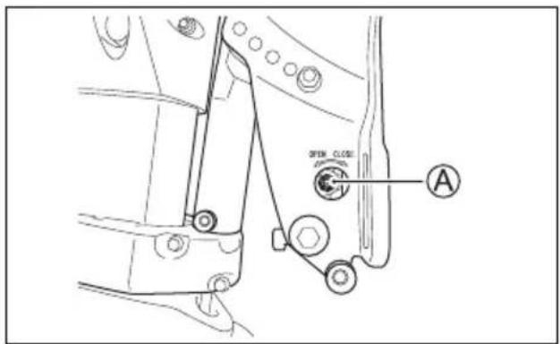

CAUTION
The motor is very heavy. When you tilt it manually, you could injure your back or slip and fall causing injury.
When you tilt the motor manually, ensure that your grip and footing are secure and that you are able to support the weight of the engine.
TILT LOCK LEVER
The tilt lock lever is provided so you can support the motor in a tilted position for non-moving engine support.
To set the tilt lock lever:
- Tilt the motor all the way up using the power trim and tilt.
- Pull down the tilt lock lever ① to hold the motor in the fully raised position.
- Lower the motor using the power trim and tilt, until the motor is supported by the tilt lock lever.
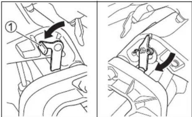
To release the lever, tilt the motor all the way up using the power trim and tilt, and pull up the tilt lock lever.


WARNING
If you do not take proper precautions when tilting up the motor, fuel may leak out.
Disconnect the fuel line whenever you leave the motor tilted up for a long period of time.

CAUTION
The remote Power Trim and Tilt switch will work when the ignition switch is off. If someone activates the switch while you are moving the tilt lock lever, your hand could be injured.
Keep all persons away from the remote Power Trim and Tilt switch while you are moving the tilt lock lever.
NOTICE
Damage can occur if you use the tilt lock lever other than when the boat is moored or is otherwise stationary.
The tilt lock lever relieves pressure from the power trim and tilt and should only be used when the boat is stationary. Do not use the tilt bracket when trailering your boat and motor. Refer to the TRAILERING section of this manual.
INSPECTION BEFORE BOATING
WARNING
Failure to inspect your boat and motor before beginning a trip can be hazardous.
Before boating, always perform the inspections described in this section.
It is important to make sure that your boat and motor are in good condition and that you are properly prepared for an emergency.
Always perform the following checks before you begin boating:
- Make sure that you have enough fuel for the intended run.
- Check the level of engine oil in the sump.
NOTICE
Running the engine with an insufficient amount of oil can cause serious engine damage.
Always check the oil level before each trip and add oil if necessary.
To check the oil level:
NOTE:
To avoid an incorrect assessment of engine oil level, check the level only when the engine has cooled.
- Place the motor in a vertical position, and remove the motor cover by unlocking the lever.

- Pull out the oil dipstick ① and wipe oil off with a clean cloth.

NOTE:
If the engine oil is contaminated or discolored, replace with fresh engine oil (Refer to Inspection and maintenance/engine oil section).
- Insert the dipstick all the way into the engine, then remove it again.

The oil on the dipstick should be between the upper and lower limits shown on the stick.
If the oil level indication is near the lower limit, add enough oil to raise the level to the upper limit.
To fill the engine oil:
- Remove the oil filler cap.
- Fill the recommended engine oil to the upper level.
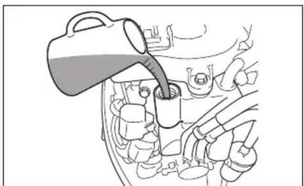
NOTICE
Running the engine with an excessive amount of oil can damage the engine.
Do not overfill the engine with oil.
-
Tighten the oil filler cap securely.
-
Check the battery solution level.
The level should be kept between the MAX and the MIN level lines at all times. If the level drops below the MIN level line, refer to MAINTENANCE section.
• Make sure that the battery leads are securely connected to the battery terminals. - Visually check the propeller to make sure it is not damaged.
• Make sure that the motor is securely mounted to the transom. - Make sure that the tilt pin is securely installed in the proper position.
• Make sure the starter rope is free from any evidence of fraying or wear.
• Make sure you have the boating safety and emergency equipment on board.
• Make sure that the emergency stop switch operates properly. - Make sure the obstacle is not attached to water intake hole.
BREAK-IN
Proper operation during this break-in period will help ensure maximum life and performance from your engine. The following guidelines will explain proper break-in procedures.
NOTICE
Failure to follow the break-in procedures described below can result in severe engine damage.
Be sure to follow the engine break-in procedures described below.
Break-in period: 10 hours
Break-in procedure
- For the initial 2 hours:
Allow sufficient idling time (about 5 minutes) for the engine to warm up after cold engine starting.
NOTICE
Running at high speed without sufficient warm-up may cause severe engine damage such as piston seizure.
Always allow sufficient idling time (5 minutes) for the engine to warm-up before running at high speed.
After warming up, run the engine at idling speed or the lowest in-gear speed for about 15 minutes.
During the remaining 1 hour and 45 minutes, if safe boating conditions permit, operate the engine in gear at less than 1/2 (half) throttle (3000 r/min.).
NOTE:
You may throttle up beyond the recommended operating range to plane your boat, then immediately reduce the throttle to the recommended operating range.
- For the next 1 hour:
Safe boating conditions permitting, operate the engine in gear at 4000 r/min. or at three-quarter throttle. Avoid running the engine at full throttle.
- Remaining 7 hours:
Safe boating conditions permitting, operate the engine in gear at desired engine speed. You may occasionally use full throttle; however do not operate the engine continuously at full throttle for more than 5 minutes at any time.
NOTICE
Running continuously at full throttle for more than 5 minutes at a time during the last 7 hours of break-in operation may cause severe engine damage such as seizure.
During the last 7 hours of break-in operation, do not operate at wide open throttle for more than 5 minutes at a time.
OPERATION
BEFORE ATTEMPTING TO START THE ENGINE
- The motor has been lowered into the water.
- The fuel hose is securely connected to the fuel tank and the motor.

NOTICE
If spilled gasoline is just left on painted surface, it may cause a stain or discoloration of the surface coating.
Wipe off any spilled gasoline immediately with a soft cloth etc.
- Twist the air-vent screw ① on the fuel tank cap counterclockwise to open the vent.

- Set the release lever ② to the "Lock" position. (DF25A/25AR/30A/30AR/30AQ)

- Make sure that the motor is in "NEUTRAL".

NOTICE
When the motor is in gear, the recoil starter cannot be operated and attempting to use it can damage the recoil starter.
Make sure that the motor is in "NEUTRAL" before pulling the recoil starter rope.
- The lock plate is in place and the end of the emergency stop switch cord is attached to a part of your body.


WARNING
Failure to properly attach the emergency stop switch cord or to take proper precautions to help ensure that the emergency stop switch works as intended may result in serious injury or death to the operator or passengers.
Always take the following precautions:
- Make sure that the emergency stop switch cord is fastened securely to the operator's wrist or to an appropriate clothing area (belt etc.).
- Ensure that no obstructions impede or restrict emergency stop switch operation.
- Be careful not to pull the stop switch cord or knock out the lock plate during normal operation. The motor will stop abruptly, and the loss of forward motion may unexpectedly throw occupants forward.
NOTE:
A spare plastic lock plate is provided for temporary use only. Remove it from the cord and place it in a safe place on board your boat. If you lose or break the emergency stop switch cord/lock plate assembly, replace it as soon as possible so that you can resume normal use of the emergency stop switch.
STARTING THE ENGINE
WARNING
Exhaust gas contains carbon monoxide, a dangerous gas that is difficult to detect because it is colorless and odorless. Breathing carbon monoxide can cause death or severe injury.
Never start the engine or let it run indoors or where there is little or no ventilation.
NOTE:
- If the engine fails to start, check the emergency stop switch lock plate. If the lock plate is not in position, the engine cannot be started.
- The starter motor can operate even with the lock plate not in position; however, the engine cannot be started.
NOTE:
Perform the following prior to starting if your motor is brand-new or there is no fuel in the fuel tank:
Fill the fuel tank with fresh gasoline.
Squeeze the fuel line priming bulb several times until you feel resistance.
Pull the starter grip sharply several times or operate the starter motor to fill the fuel line with fuel, then follow the normal starting procedure steps.
TILLER HANDLE MODEL
- Squeeze the fuel line priming bulb several times until you feel resistance.

- Make sure that the throttle control grip is in the fully closed position.

3. a) Recoil starter model
Firmly grasp the starter grip ① and pull slowly until resistance is felt. When you feel it engage, pull the rope sharply to start the engine. Do not release the rope when it is pulled out. Hold the rope and allow it to recoil slowly.
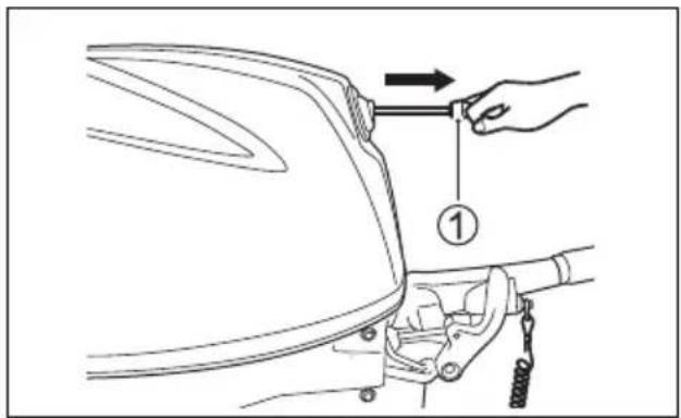
WARNING
If the battery cables are not connected to a battery and they contact each other while the engine is running, it could cause electrical system damage and could present a fire hazard.
If you are not using a battery with an electric starter models, you must insulate the terminal ends of the battery cables so that they will not touch each other.
NOTICE
If you pull the starter grip while the engine is running, the starter system can be damaged.
Never pull the starter grip while the engine is running.
b) Electric starter model Push the starter button ②.
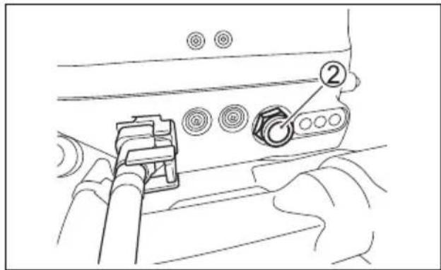
NOTICE
If you push the starter button for more than 5 seconds, the starter system could be damaged.
Never push the starter button for more than 5 seconds.
NOTICE
If you push the starter button while the engine is running, the starter system could be damaged.
Never push the starter button while the engine is running.
NOTE:
If the engine fails to start after 5 seconds, wait 10 seconds and try again.
NOTICE
If the Caution System is not working properly, you may not be alerted to a condition that could cause damage to your outboard motor.
If the caution lamp does not come on briefly once the starter system is operated, the caution lamp may be broken or a failure may exist in the system circuit. Consult your authorized Suzuki marine dealer.
- Warm up the engine for about 5 minutes.
NOTICE
Operating the engine at high RPM or “wide open throttle” immediately after starting the engine without allowing the engine to warm up may cause engine failure.
Always allow the engine to warm up sufficiently before operating it at high speeds.
REMOTE CONTROL MODEL
- Squeeze the fuel line priming bulb several times until you feel resistance.

- Make sure that the warm-up lever is in the fully closed position.

- Turn the ignition key to the "ON" position.
- Turn the ignition key to the "START" position.
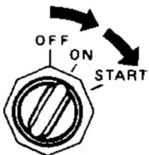
![graph TD A["Hexagon with diagonal lines forming 'OFF ON START'"] --> B["Arrow to OFF"] B --> C["Arrow to ON"] C --> D["Arrow to START"]](/content/2026/06/1405538/images/46c0b1326e5d6ceb26f59650dadfd348d786ef745434846cc4e2bf53484a92e1.jpg)
NOTICE
If you turn the ignition key to the "START" position for more than 5 seconds, the starter system could be damaged.
Never turn the ignition key to the "START" position for more than 5 seconds.
NOTICE
If you turn the ignition key to the "START" position while the engine is running, the starter system could be damaged.
Never turn the ignition key to the "START" position while the engine is running.
NOTE:
If the engine fails to start after 5 seconds, wait 10 seconds and try again.
NOTICE
If the Caution System is not working properly, you may not be alerted to a condition that can cause damage to your outboard motor.
If the caution lamp does not come on or the buzzer does not sound when the ignition key is turned on, the caution lamp or buzzer may be broken or a failure may exist in the system circuit. Consult your authorized Suzuki marine dealer.
- Warm up the engine for about 5 minutes.
NOTICE
Operating the engine at high RPM or “wide open throttle” immediately after starting the engine without allowing the engine to warm up may cause engine failure.
Always allow the engine to warm up sufficiently before operating it at high speeds.
Cooling water check
As soon as the engine starts, water should spray out of the pilot water hole ①, indicating that the water pump and cooling system are working properly. If you notice that water does not spray out of the pilot water hole, stop the engine as soon as possible and consult your authorized Suzuki Marine Dealer.

NOTICE
Never operate your outboard motor when there is no water coming out of the pilot water hole, or severe damage can result.
After starting the engine, check to make sure that there is water coming out of the pilot water hole.
WARNING
Operating the boat when the emergency stop switch is not operating properly can be hazardous.
Before starting off, check to make sure that the emergency stop switch operates properly.
EMERGENCY STARTING
NOTE:
The electric starter models are equipped with a recoil starter as the back-up system for emergency starting. Therefore, an additional emergency starter rope is not provided.
If you must get the engine running, but are unable to do so because of recoil starter system failure, you can use the emergency starting procedure to start the engine.
WARNING
If you touch electrical components when rope-starting the engine, you can get a severe electrical shock.
When rope-starting the engine, be careful not to touch electrical components such as ignition coils or spark plug leads.
To start the engine when the recoil starter fails:
- Shift the motor into "NEUTRAL".
WARNING
When you use the emergency starting procedure, the start-in-gear protection system will not work. If the shift lever is not in the "NEU-TRAL" position, the boat can start off unexpectedly when the engine is started, throwing occupants or causing an accident.
Make sure that the shift lever is in the "NEUTRAL" position before attempting to start the motor using the emergency starting procedure.
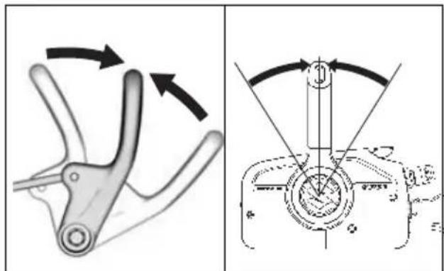
- Remove the motor cover by turning the lock lever in the direction of the arrow and lifting the cover off.

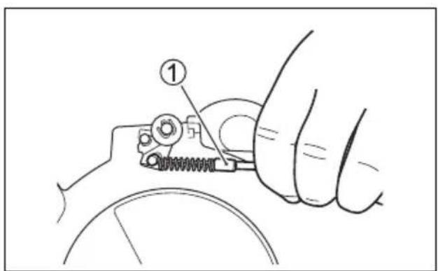
- Remove the NSI cable ① from the recoil starter.
- Remove the two bolts securing the silencer in place. Remove the silencer.

- Remove the four bolts securing the recoil starter assembly and timing belt cover in place.

-
Disconnect the recoil starter assembly from the timing belt cover and lift the recoil starter assembly.
-
Reinstall the timing belt cover and secure it with a bolt.

- Secure the NSI cable with suitable rope as shown.

NOTE: Make sure that the wire harness do not touch to the flywheel and the timing belt.
- Tie a knot in one end of the emergency starter rope located in the tool kit. Tie the other end around the screw-driver handle in the tool kit.
- Hook the knotted end of the rope in the pulley notch and wind the rope around the pulley in a clockwise direction.
- Put the emergency stop switch lock plate in place.
- Remote control model: Turn the ignition key to the "ON" position.
- After following steps of the normal starting procedure, pull the emergency starter rope sharply to start the engine.

WARNING
If you attempt to reinstall the recoil starter assembly or motor cover after starting the engine you can be injured.
Do not attempt to reinstall the recoil starter assembly or motor cover after starting the engine.
WARNING
When the engine is running, there are many moving parts that could cause severe personal injury.
When the engine is running, keep your hands, hair, clothing, etc., away from the engine.
NOTE:
Be sure to have the starter system repaired as soon as possible. You should not continue to use the emergency starting procedure for routine engine starting.
SHIFTING AND SPEED CONTROL
NOTICE
Severe engine damage may occur if (a) engine speed is not allowed to return to idle and boat speed is not reduced when shifting from "FORWARD" to "REVERSE" or from "REVERSE" to "FORWARD", or (b) care is not taken when operating the boat in reverse.
Always allow the engine speed to return to idle before shifting. Exercise caution and use minimal speed when operating the boat in reverse. Be sure the handle/shift lever is in the desired position before accelerating.
NOTICE
If you shift gears when the engine is not running, the shifting mechanism can be damaged.
Avoid shifting gears when the engine is not running.
TILLER HANDLE MODEL Shifting
To shift the motor into "FORWARD", set the throttle control grip to the idle position and pull the shift lever towards you firmly.
To shift into "REVERSE", put the tilt lock lever into the "lock" position, set the throttle to the idle position, and push the shift lever away from you firmly.
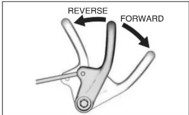
Speed Control
After shifting, control the engine speed by twisting the throttle control grip.

REMOTE CONTROL MODEL Shifting
To shift into "FORWARD", squeeze the lockout lever on the control handle and move the control handle forward to approximately position Ⓐ, as shown in the illustration.
To shift into "REVERSE", squeeze the lockout lever on the control handle and move the control handle rearward to approximately position Ⓑ, as shown in the illustration.

Speed Control
To increase speed after you have shifted into gear, continue moving the control handle forward or rearward.
WARNING
Since the same handle is used for shifting and speed control it is possible to move the handle past the detent and engage the throttle. This can cause the boat to move suddenly resulting in personal injury or property damage.
You must be careful not to move the control handle too far forward or rearward when shifting.
STOPPING THE ENGINE
NOTE:
When it is necessary to stop the engine in an emergency, pull the emergency stop switch lock plate out of the emergency stop switch by pulling the emergency stop switch cord.
TILLER HANDLE MODEL
To stop the engine:
- Turn the throttle control grip to the idle position.
- Shift into "NEUTRAL".
- After operating at full throttle, cool off the engine a few minutes by allowing it to idle or troll at low speed.
- Push and hold in the stop button Ⓐ until the engine stops.

- After stopping the engine, disconnect the fuel connector from outboard motor.

WARNING
If you leave the motor stopped for a long period of time with the fuel line connected, fuel can leak out.
Disconnect the fuel line, whenever you leave the motor stopped for a long period of time.
NOTICE
If spilled gasoline is just left on painted surface, it may cause a stain or discoloration of the surface coating.
Wipe off any spilled gasoline immediately with a soft cloth etc.
- Turn the air-vent screw on the fuel tank cap clockwise to shut the vent.
REMOTE CONTROL MODEL
To stop the engine:
- Shift into "NEUTRAL".
- After operating at full throttle, cool off the engine a few minutes by allowing it to idle or troll at low speed.
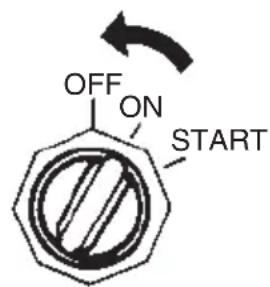
- Turn the ignition key to the "OFF" position. Always leave the ignition key in the "OFF" position when the motor is not running, or battery can discharge.

- After stopping the engine, disconnect the fuel connector from outboard motor.

WARNING
If you leave the motor stopped for a long period of time with the fuel line connected, fuel can leak out.
Disconnect the fuel line, whenever you leave the motor stopped for a long period of time.
NOTICE
If spilled gasoline is just left on painted surface, it may cause a stain or discoloration of the surface coating.
Wipe off any spilled gasoline immediately with a soft cloth etc.
- Turn the air-vent screw on the fuel tank cap clockwise to shut the vent.

WARNING
Unauthorized use of your boat could lead to an accident or damage to your boat.
To prevent unauthorized use of your boat, be sure to remove the key and emergency stop switch lock plate when the boat is unattended.
NOTE:
To make sure that the emergency stop switch operates properly, stop the engine occasionally by pulling out the lock plate, while operating the engine at idling speed.
MOORING
The motor should be tilted up out of the water when you moor the boat in shallow water or if the motor will not be used for some time, to protect it from damage by underwater obstacles at low tide or corrosion from salt water.
Refer to the TILT UP LOCK ARM section (DF25A/25AR/30A/30AR) or TILT LOCK LEVER section (DF25AT/25ATH/30AT/30ATH/30AQ) for details on how to tilt up the motor.
WARNING
If you leave the motor tilted up for a long period of time with the fuel line connected, fuel can leak out.
Disconnect the fuel line whenever you leave the motor tilted up for a long period of time.
NOTICE
Improperly securing your boat may cause damage to your boat or motor, or other property damage.
Do not allow your motor to rub against quay walls, piers or other boats when the boat is tied up.
OPERATION IN SHALLOW WATER (DF25A/25AR/30A/30AR)
When operating your outboard motor in shallow water, use the shallow water position to tilt the motor slightly from the normal trim angle. When using the shallow water position, however, you should only operate the motor at slow speeds. Refer to the SHALLOW WATER POSITION section.
WARNING
When the shallow water position is used, the tilt lock will not work. As a result, forces such as from propeller thrust during operation in "REVERSE" gear, rapid deceleration, and striking an underwater object can cause the motor to lift out of the water, resulting in personal injury.
When using the shallow water position, proceed with caution and only at very low speeds.
NOTICE
If you do not take proper precautions when operating your boat in shallow water, your outboard motor or boat could be damaged.
- When you operate your motor in shallow water using the shallow water position, make sure that the water intake holes remain in the water at all times and that water is always spraying out of the water discharge hole.
- Do not allow your motor to hit bottom, particularly when operating in “REVERSE” gear, or serious damage can result. When the motor hits bottom while operating in “REVERSE” gear, the shock acts directly on the transom, and both the motor and the boat could be damaged.
OPERATION IN SHALLOW WATER (DF30AQ)
When operating your boat in shallow water, it may be necessary to tilt the motor higher than the normal trim angle. When you tilt the motor beyond the normal trim angle, however, you should only operate the boat at slow speeds. After returning to deep water, be sure to lower the motor to the normal trim angle.
To tilt the motor higher than the normal trim angle:
- Stop the engine.
- Move the release lever ① to the release position.

- Slowly tilt the motor up to appropriate trim angle.

- Move the release lever ① to the lock position.

To lower motor back down:
- Shift into "NEUTRAL".
- Move the release lever ① to the release position.
- Push the handle on the back of motor cover and slowly let the motor down.
- Move the release lever ① to the lock position.
WARNING
When the motor is beyond the maximum trim position, the swivel bracket will not have side support from the clamp bracket and the tilt system will be unable to cushion the engine if the lower unit strikes an obstruction. This could lead to occupant injury. In addition, beyond the maximum trim position, the water intake holes may be above the water line, which can result in severe engine damage from overheating.
Do not operate the engine above 1500 r/min or operate the boat in a planning attitude with the engine beyond the maximum trim position.
NOTICE
If the motor hits bottom, serious damage can occur.
Do not allow the motor to hit bottom. If the motor does strike bottom, inspect it immediately for damage.
OPERATION IN SHALLOW WATER (DF25AT/25ATH/30AT/30ATH)
When operating your boat in shallow water, it may be necessary to tilt the motor higher than the normal trim angle. When you tilt the motor beyond the normal trim angle, however, you should only operate the boat at slow speeds. After returning to deep water, be sure to lower the motor to the normal trim angle.
To tilt the motor higher than the normal trim angle, use the Power Trim and Tilt switch. Refer to POWER TRIM AND TILT section.
WARNING
When the motor is beyond the maximum trim position, the swivel bracket will not have side support from the clamp bracket and the tilt system will be unable to cushion the engine if the lower unit strikes an obstruction. This could lead to occupant injury. In addition, beyond the maximum trim position, the water intake holes may be above the water line, which can result in severe engine damage from overheating.
Do not operate the engine above 1500 r/min or operate the boat in a planning attitude with the engine beyond the maximum trim position.
NOTICE
If the motor hits bottom, serious damage can occur.
Do not allow the motor to hit bottom. If the motor does strike bottom, inspect it immediately for damage.
OPERATION IN SALT WATER
After operating the motor in salt water, you should flush the water passages with clean, fresh water as outlined in the FLUSHING THE WATER PASSAGES section. If you do not flush the water passages, salt can corrode the motor and shorten its life.
When operating your outboard motor in freezing temperatures, you should keep the lower unit submerged in the water at all times.
When taking motor out of the water, stand it up in a vertical position until the cooling system drains completely.
NOTICE
If you leave your outboard motor out of the water in freezing temperatures with water still in the cooling system, the water can freeze and expand, causing severe damage to the motor.
When your outboard is in the water in freezing temperatures, keep the lower unit submerged in the water at all times. When the motor is stored out of the water in freezing temperatures stand it up in the vertical position so that the cooling system drains completely.
MOTOR REMOVAL AND TRANSPORTING
MOTOR REMOVAL TILLER HANDLE MODEL
- Make sure that the engine has stopped completely.
- Remove the fuel hose from the motor.
- Remove the motor cover.
- Drain the gasoline from the engine fuel line as follows:
(1) Remove the seven (7) bolts using 8 mm box wrench, then remove the starboard side cover.

(2)Tilt the motor fully down.
(3)Loosen the drain screw ① and drain the gasoline from fuel vapor separator into a suitable container.

WARNING
Gasoline is extremely flammable and toxic. It can cause a fire and can be hazardous to people and pets.
Use a proper, safe container to store any gasoline drained from the outboard motor. Keep gasoline away from sparks, flames, people, and pets.
(4)After draining completely, retighten drain screw ①.
NOTICE
If spilled gasoline is just left on painted surface, it may cause a stain or discoloration of the surface coating.
Wipe off any spilled gasoline immediately with a soft cloth etc.
- Install the starboard side cover.
- Install the motor cover.
- Remove the mounting bolts.
- Loosen the clamp screws.
- Lift the motor off the transom.
- Stand the motor vertically and drain the water from the lower unit.
- To carry, hold the motor by gripping the tiller handle bracket and engine side cover.

REMOTE CONTROL MODEL
If it is necessary to remove the outboard motor from your boat, we recommend that you ask your authorized Suzuki Marine Dealer to do the work for you.
MOTOR TRANSPORTING
When transporting the motor, place the motor either vertically or horizontally.
Vertical transport:
Attach the motor to the carrier by securing clamp bracket with two clamp screws.
Never use display stand for transportation of the motor.

Horizontal transport:
- Drain the gasoline from the engine fuel line. Refer to the MOTOR REMOVAL section.
- Raise the tiller handle and rest the motor on a case protector with the port side downwards as shown.


WARNING
Spilled fuel or fuel vapor can cause a fire and is hazardous to health.
Always take the following precautions:
- Drain the fuel from the fuel line and fuel vapor separator before transporting the boat/outboard motor and before removing the motor from the boat.
- DO NOT lay motor on its side without draining fuel.
- Keep the motor away from open flames or sparks.
- Wipe up spilled fuel immediately.
NOTICE
If you do not take proper precautions when transporting your outboard, it can be damaged.
- Do not rest the engine in any of the positions shown below, as water and oil may enter the cylinder through the exhaust port or the outer casings may be damaged.
- Do not place the engine on its side before the cooling water has drained from it completely, as water may enter the cylinder through the exhaust port and cause problems.
INCORRECT

NOTICE
If you let the lower unit of your outboard sit higher than the power head during transporting or storing, water may trickle into the power head, causing damage to the engine.
Never let the lower unit sit higher than the power head when transporting or storing your outboard.
TRAILERING
When trailering your boat with the motor attached, keep the motor in the normal operating position unless there is not enough ground clearance. If you need more ground clearance, trailer the motor in a tilted position using a trans-som saver bar or similar device to support the weight of the motor.

NOTICE
If you use the tilt up lock arm/tilt lock lever to hold the motor in the fully tilted up position when trailering the boat, towing motion or poor road surfaces may cause unexpected tilt lock release, resulting in damage to the motor and the tilt lock mechanism.
Never use the tilt up lock arm/tilt lock lever to hold the motor in the fully tilted up position when trailering the boat. Use a transom saver bar or similar device to support the weight of the motor.
INSPECTION AND MAINTENANCE
MAINTENANCE SCHEDULE
It is important to inspect and maintain your outboard motor regularly. Follow the chart below. At each interval, be sure to perform the indicated service. Maintenance intervals should be judged by number of hours or number of months, whichever comes first.
WARNING
Exhaust gas contains carbon monoxide, a dangerous gas that is difficult to detect because it is colorless and odorless. Breathing carbon monoxide can cause death or severe injury.
Never start the engine or let it run indoors or where there is little or no ventilation.
| Item to be serviced\Interval | Initial 20 hrs. or 1 month | Every 100 hrs. or every 12 months | Every 200 hrs. or every 12 months | Every 300 hrs. or every 36 months |
| Spark plug I | ||||
| Breather & Fuel line I I | ||||
| Engine oil R R | ||||
| Gear oil R R | ||||
| Lubrication I I | ||||
| Anodes (external) I I | ||||
| * Anodes (internal cylinder block/cylinder head) | I | |||
| Bonding wire I I | ||||
| Battery I I | ||||
| * Engine oil filter R R | ||||
| * Low pressure fuel filter | I | I | ||
| Replace every 400 hours or every 2 years. | ||||
| * Low pressure fuel pump filter | Replace every 1000 hours. | |||
| * Timing belt | I | |||
| Replace every 4 years. | ||||
| * Idle speed I | I | |||
| * Valve clearance (lash) | I | I | ||
| * Water pump | I | |||
| * Water pump impeller | I | R | ||
| * Propeller nut & pin | II | |||
| * Bolts & Nuts | T | T | ||
| * Thermostat | I | |||
| * Air cleaner element | I | |||
I: Inspect and clean, adjust, lubricate, or replace, if necessary T: Tighten R: Replace
NOTE:
Water-separating fuel filter
Replace the filter element every 12-months (or more frequently if recommended by the filter manufacturer).

WARNING
Improper maintenance or failure to perform recommended maintenance can be hazardous. Poor maintenance or lack of maintenance increases the chance of an accident or equipment damage.
Be sure to have maintenance performed according to the schedule in the above chart. Suzuki recommends that only your authorized Suzuki marine dealer or a qualified service mechanic perform maintenance on those items in the chart above which are marked with an asterisk (*). You may perform maintenance on the unmarked items by referring to the instructions in this section if you have mechanical experience. If you are not sure whether you can successfully complete any of the unmarked maintenance jobs, ask your authorized Suzuki marine dealer to do the maintenance for you.

WARNING
The safety of you and your passengers depends on how well you maintain your outboard motor.
Follow all inspection and maintenance instructions carefully. If you do not have prior mechanical experience, do not attempt to perform maintenance on your outboard motor. You could be injured or may damage the motor.
NOTICE
The maintenance intervals in the chart are designed for normal usage of your outboard motor. If your outboard motor is used under severe conditions as outlined below, you may need to perform maintenance more often than indicated in the chart.
• Frequent full throttle operation
- Prolonged continuous operation at the maximum speed
- Prolonged continuous operation at idling speed or trolling speed
- Frequent operation in muddy, silty, sandy, acidic or shallow water
• Operation without appropriate warmup
- Frequent abrupt acceleration and deceleration
- Frequent shift operation Failure to perform maintenance more frequently could result in damage.
Consult your authorized Suzuki marine dealer regarding appropriate maintenance intervals for your usage conditions. When replacing parts on your outboard motor, Suzuki strongly recommends that you use genuine Suzuki parts or their equivalent.
TOOL KIT
A tool kit is provided with your outboard motor. Keep the kit on board your boat and make sure that all of the items provided remain in the kit.
The tool kit contains the following items:
① Tool bag
② 8 mm Box wrench
③ 10 × 12 mm Box wrench
④ 16 mm Box wrench
⑤ Combination screw driver
⑥ Screwdriver handle
⑦ Pliers
⑧ Hexagon wrench 8 mm
⑨ Emergency starter rope

NOTE:
An emergency starter rope⑨ is not provided with the electric starter models.
SPARK PLUG
Your outboard motor comes equipped with the following “standard” spark plug for normal usage.
NGK MR6K-9 Standard
NOTICE
Non-resistor types of spark plugs will interfere with the function of the electronic ignition, causing misfiring, or causing problems with other electronic boat equipment and accessories.
Use ONLY resistor type spark plugs in your outboard motor.
A normally operating spark plug is very light-brown in color. If the standard plug is not suitable for your operating, consult your authorized Suzuki outboard motor dealer.


NOTICE
Use of improper spark plugs or improperly tightening spark plugs can cause severe engine damage.
- Do not experiment with other spark plug brands unless you can determine that they are directly equivalent to the specified brand, or you may experience engine damage which will not be covered under warranty. Note that aftermarket cross-reference charts may not be accurate.
- To install a spark plug; seat it as far as possible by hand, then use a wrench to tighten it to either the recommended torque setting or the specified rotation angle.
| Tightening torque | |
| 10 – 12 N·m(1.0 – 1.2 kg·m, 7.0 – 8.5 lb·ft) | |
| Rotation angle | |
| New plug 1/2 – | 3/4 of a turn |
| Re-use plug 1/1 | 12 – 1/8 of a turn |
- Do not overtighten or cross-thread a spark plug, as this will damage the aluminum threads of the cylinder head.
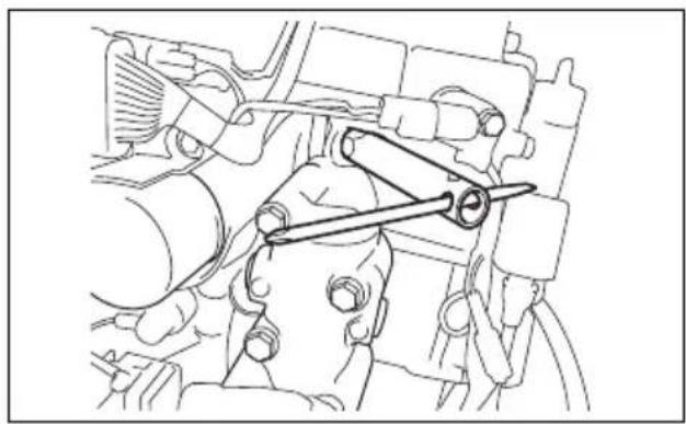
To maintain a strong spark, you should clean and adjust the plugs at the intervals shown in the maintenance chart. Remove carbon deposits from the spark plugs using a small wire brush or spark plug cleaner, and adjust the gap according to the following chart:
| Spark plug gap | 0.8 – 0.9 mm(0.031 – 0.035 in.) |


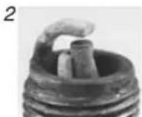
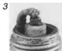


- Excessive wear 2. Breakage 3. Melting
- Erosion 5. Yellow deposits 6. Oxidation
NOTE:
If the spark plug condition is found as shown in the illustration above, ensure it is replaced with new one. Otherwise, it will cause difficulty in starting the engine, increase fuel consumption, and result in engine troubles.
BREATHER AND FUEL LINE
Inspect the breather and fuel line for leaks, cracks, swelling, or other damage. If the breather and fuel line is damaged in any way, it must be replaced. Consult your authorized Suzuki Marine Dealer if it is necessary to replace them.


WARNING
Fuel leakage can contribute to an explosion or fire, resulting in serious personal injury.
Have your authorized Suzuki Marine Dealer replace the fuel line if there is any evidence of leaking, cracking or swelling.
ENGINE OIL

WARNING
Never perform any ENGINE OIL procedure with the motor running, as serious injury can occur.
The motor must be shut off before any ENGINE OIL procedures are performed.
NOTICE
Extended trolling can reduce oil life. Your engine may be damaged if you do not change engine oil more frequently under this type of use.
Change your engine oil more frequently if your engine is used for extended trolling.
Engine oil change
The oil should be changed when engine is warm so that the oil will drain thoroughly from the engine.
To change the engine oil:
- Place the motor in a vertical position and remove the motor cover.
- Remove the oil filler cap ①.

- Place a drain pan under the engine oil drain plug.

CAUTION
The engine oil temperature may be high enough to burn your fingers when the drain plug is loosened.
Wait until the drain plug is cool enough to touch with bare hands before removing it.
- Remove the engine oil drain screw ② and gasket ③, then let the engine oil drain.

- After draining, secure the engine oil drain plug with a new gasket.
NOTICE
A previously-used gasket may leak, resulting in engine damage.
Do not re-use gaskets. Be sure to always use new gaskets.
- Fill with recommended engine oil to the upper level.
Oil capacity: 1.5 L
- Check the engine oil level.
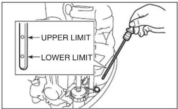
NOTE:
To avoid incorrect measurement of engine oil level, check oil level only when the engine has cooled.
- Reinstall the oil filler cap.
WARNING
Engine oil can cause injury to people or pets. Repeated, prolonged contact with used engine oil may cause skin cancer. Even brief contact with used oil may irritate skin.
- Keep new and used oil away from children and pets.
- Wear a long-sleeve shirt and waterproof gloves when handling oil.
- Wash with soap if oil contacts your skin.
- Launder any clothing or rags that are wet with oil.
NOTE:
Recycle of properly dispose of used engine oil. Do not throw it in the trash, or pour it on the ground, down a drain, or into the water.
GEAR OIL
To check the gear oil level, remove the upper oil level plug and look into the hole. The oil level should be at the bottom edge of the hole. If the oil level is low, add the specified gear oil until the level reaches the bottom edge of the hole. Then, reinstall and tighten the plug.
To change the gear oil:
- Tilt up the motor fully.
(Refer to OPERATION OF TILTING SYSTEMS section.)
Turn the starboard side of the motor downward. So that the drain plug ① is located at the bottom. Place a drain pan under the lower casing.

- Remove the gear oil drain plug ①, then remove the gear oil level plug ②.
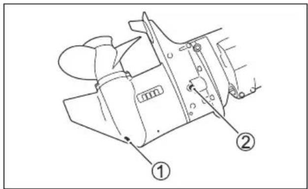
- After the oil has drained completely, lower the motor to an upright position. Inject the specified gear oil into the lower drain hole until it just starts to come out of the upper level hole. Approximately 0.33 L (0.3/0.3 US/ Imp. qt.) of oil will be required.

- Reinstall and tighten the gear oil level plug ②, then quickly reinstall and tighten the gear oil drain plug ①.
NOTE:
To avoid insufficient injection of gear oil, check the gear oil level 10 minutes after doing the procedure in the step 4. If the oil level is low, slowly inject the gear oil up to the correct level.
WARNING
Gear oil can cause injury to people or pets. Repeated, prolonged contact with used gear oil may cause skin cancer. Even brief contact with used oil may irritate skin.
- Keep new and used oil away from children and pets.
- Wear a long-sleeve shirt and waterproof gloves when handling oil.
- Wash with soap if oil contacts your skin.
- Launder any clothing or rags that are wet with oil.
NOTE:
Recycle or properly dispose of used gear oil. Do not throw it in the trash, or pour it on the ground, down a drain, or into the water.
NOTICE
If fishing line wraps around the rotating propeller shaft, the propeller shaft oil seal can become damaged and can allow water to enter the gear case causing severe damage.
If the gear oil has a milky color, it is contaminated with water. Immediately contact your authorized Suzuki marine dealer for advice. Do not operate your outboard until the oil is changed and the cause of the contamination is corrected.
LUBRICATION
Proper lubrication is important for the safe, smooth operation and long life of each working part of your outboard motor. The following chart shows the lubrication points of your motor and the recommended lubricant:
LOCATION LUBRICANT

Throttle link (Remote control model)
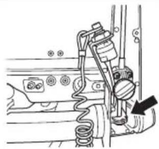

Throttle cable (Tiller handle model)
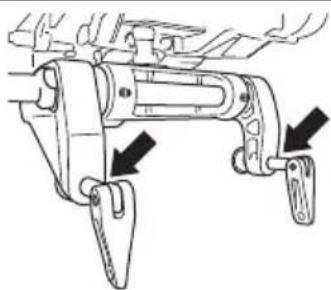
Clamp screw

Propeller shaft
Marine-grade water resistant grease
| Swivel bracket | Marine-grade water resistant grease (Grease Gun) |
| Steering bracket |
NOTE:
Before applying grease through the steering bracket grease nipple, lock the motor in the fully tilted up position.
ANODES
The motor is protected from exterior corrosion by anodes. These pieces of anodes control electrolysis and prevent corrosion. The anodes will corrode in place of the parts they are protecting. You should periodically inspect each of the anodes and replace them when 2/3 of the metal has corroded away.

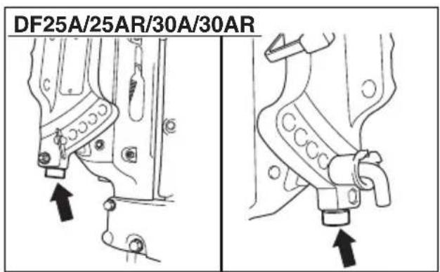
If anodes are not properly maintained, underwater aluminum surfaces (such as the lower unit) will suffer galvanic corrosion damage.
• Periodically inspect anodes to make sure they have not become detached.
- Do not paint anodes, as this will render them ineffective.
- Periodically clean anodes with a wire brush to remove any coating which might decrease their protective ability.
NOTE:
Consult your authorized Suzuki Marine Dealer for inspection and replacement of internal anodes attached to the cylinder block/cylinder head.
BONDING WIRE
DF25A/25AR/30A/30AR
Bonding wire is used to electrically connect the engine components so they exist in a common ground circuit. This allows them to be protected against electrolysis by the anodes. This wire and it terminals should be checked periodically to be sure they have not been damaged.

BATTERY
The battery solution level must be kept between the MAX and the MIN level lines at all times. If the level drops below the MIN level line, add DISTILLED WATER ONLY until the battery solution level reaches the MAX level line.
WARNING
Battery acid is poisonous and corrosive, and can cause severe injury.
Avoid contact with eyes, skin, clothing, and painted surfaces. If battery acid comes in contact with any of these, flush immediately with large amounts of water. If acid contacts the eyes or skin, get immediate medical attention.
WARNING
If you are not careful when checking or servicing the battery, you can cause a short circuit, which could result in an explosion, fire, or circuit damage.
Disconnect the negative (black) cable when checking or servicing the battery. Be careful not to allow a metal tool or other metal object to touch the battery's positive terminal and the motor at the same time.
WARNING
Battery posts, terminals, and related accessories contain lead and lead compounds that may be hazardous.
Wash hands after handling.
NOTICE
If you add diluted sulphuric acid to the battery after it has been initially serviced, you will damage the battery.
NEVER add diluted sulphuric acid to the battery after it has been initially serviced. Follow the battery manufacturer's instructions for specific maintenance procedures.
ENGINE OIL FILTER
The engine oil filter must be changed by an authorized Suzuki Marine Dealer periodically. Replace engine oil filter with a new one at initial 20 hours (1 month).
Replace engine oil filter with a new one at every 200 hours (12 months).
FUEL FILTER
The fuel filter must be inspected by authorized Suzuki Marine Dealer periodically.
Low pressure fuel filter
Inspect low pressure fuel filter at initial 20 hours (1 month).
Inspect low pressure fuel filter at every 100 hours (12 months).
Replace low pressure fuel filter with a new one at every 400 hours (2 years).
LOW PRESSURE FUEL PUMP FILTER
The fuel filter must be inspected by authorized Suzuki Marine Dealer periodically.
Replace low pressure fuel pump filter with a new one at every 1000 hours.
TIMING BELT
The timing belt must be changed by authorized Suzuki Marine Dealer periodically.
Inspect timing belt at every 200 hours (12 months).
Replace timing belt with a new one at every 4 years.
AIR CLEANER ELEMENT
The air cleaner element must be inspected by authorized Suzuki Marine Dealer periodically.
Inspect air cleaner element at every 200 hours (12 months).
FLUSHING THE WATER PASSAGES
After operation in muddy, brackish, or salt water, you should flush the water passages and motor surface with clean, fresh water.
If you do not flush the water passages, salt can corrode the motor and shorten its life. Flush the water passages as follows.
ENGINE RUNNING – Vertical position –
Suzuki recommends that you flush the water passages using this method.
To flush the water passages, you must obtain a commercially available engine flush device.

WARNING
Exhaust gas contains carbon monoxide, a dangerous gas that is difficult to detect because it is colorless and odorless. Breathing carbon monoxide can cause death or severe injury.
Never start the engine or let it run indoors or where there is little or no ventilation.

WARNING
Failure to take proper precautions when flushing the water passages can be hazardous.
When flushing the water passages, always take the following precautions:
- Make sure that the engine remains in NEU-TRAL. If shifted into gear, the propeller shaft will turn and could cause severe personal injury.
- Make sure the motor is properly clamped to a secure stand or boat, and remain in attendance until flushing is completed.
- Keep children and pets away from the area, and stay clear of all moving parts.
NOTICE
Severe engine damage can occur in as little as 15 seconds if the engine is started without supplying water to the cooling system.
Never start the motor without supplying water to the cooling system.
- Make sure that the motor is stopped.
- Remove the propeller.
- Install the flushing attachment ① so that the water intake holes are covered by the rubber cups on the attachment.

- Connect a garden hose to the flushing attachment and turn on the water to obtain enough flow so that plenty of excess water is flowing out from around the rubber cups on the attachment.
- Shift the motor into "NEUTRAL". Start the motor and allow it to run at idle.
- Readjust the water flow, if necessary, so that there is still plenty of excess water flowing out from around the rubber cups.
- Allow the water to continue circulating for a few minutes.
- Stop the motor, then turn off the water.
- Remove the flushing attachment.
- Clean the motor surface and apply a coat of automotive wax on the external finish of the motor.
ENGINE NOT RUNNING
- Vertical position -
- Make sure that the motor is stopped.
- Remove the plug Ⓐ from the flushing port.
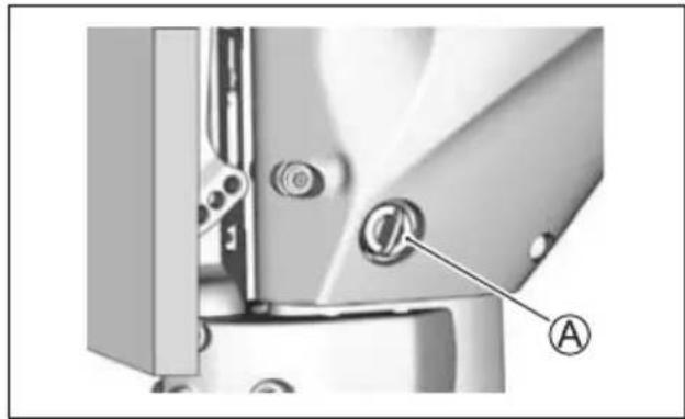
- Install garden hose by using a hose connector matched to flushing port thread Ⓑ.
Thread Ⓑ: 0.75 – 11.5 NHR (American standard hose coupling threads for garden hose applications.)
NOTE:
The hose connector (flushing attachment) matched to the flushing point thread Ⓑ is included in the crate parts.
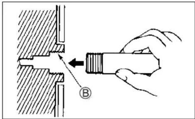
- Turn on the water to obtain a good water flow.
Flush the engine for about five minutes. - Turn off the water.
- Remove the hose and connector (if used) then reinstall the plug into the flushing port.
- Leave the motor in a vertical position until the engine is drained completely.
ENGINE NOT RUNNING
- Full tilt up position -
- Raise the engine to the full tilt up position.
- Follow the "ENGINE NOT RUNNING – Vertical position" instructions.
DO NOT RUN ENGINE IN THE FULL TILT UP POSITION.
- Lower the motor a vertical position until the engine is drained completely.
SUBMERGED MOTOR
A motor that has been accidentally submerged in water must be overhauled as soon as possible to prevent corrosion. In the event that your motor is accidentally submerged, take the following steps:
- Get the motor out of the water as soon as possible.
- Wash it thoroughly with fresh water to completely remove all salt, mud, and seaweed.
- Remove the spark plugs. Drain the water from the cylinders through the spark plug holes by manually turning the flywheel several times.
- Check if any water is evident in the engine oil. If water is seen, remove the oil drain plug and drain the oil. After draining, tighten the oil drain plug.
- Drain the fuel line and all filters.
WARNING
Gasoline is extremely flammable and toxic. It can cause a fire and can be hazardous to people and pets.
Keep flames and sparks away from gasoline. Dispose of unwanted fuel properly.
- Pour engine oil into the engine through the spark plug holes. Turn the engine over by operating the recoil starter so that oil coats the surfaces of the engine's inner parts.
NOTICE
Severe engine damage may occur if you continue cranking the engine when you encounter friction or resistance.
If you encounter friction or resistance while cranking the engine, stop at once and do not attempt to start the engine until you find and correct the problem.
- Take the motor to your authorized Suzuki Marine Dealer as soon as possible to be overhauled.
NOTICE
If the fuel supply is contaminated with water, engine damage may occur.
If the boat's fuel tank filler and vent were submerged, inspect the fuel supply to make sure it is not contaminated with water.
STORAGE PROCEDURE
MOTOR STORAGE
When storing your motor for a long period of time (for example, at the end of the boating season), it is recommended that you take your motor to your authorized Suzuki Marine Dealer. However, if you choose to prepare the motor for storage yourself, follow the procedure outlined below:
- Change the gear oil as outlined in the GEAR OIL section.
- Change the engine oil as outlined in the ENGINE OIL section.
- Fill a fuel stabilizer to the fuel tank according to the instructions on the stabilizer can.
- Flush the water passages in the motor thoroughly. Refer to the FLUSHING THE WATER PASSAGES section.
- Readjust the water flow, run the engine at about 1500 r/min. in neutral for five minutes to distribute the stabilized fuel through the engine.
- Stop the engine. Then turn off the water and disconnect the flushing attachment.
- Lubricate all other specified parts. Refer to the LUBRICATION section.
- Apply a coat of automotive wax on the external finish of the motor. If paint damage is evident, apply touch up paint before waxing.
- Store the motor in an upright position in a dry, well-ventilated area.
WARNING
When the engine is running, there are many moving parts that could cause severe personal injury.
When the engine is running, keep your hands, hair, clothing, etc., away from the engine.
NOTICE
Severe engine damage can occur in as little as 15 seconds if the engine is started without supplying water to the cooling system.
Never start the motor without supplying water to the cooling system.
NOTICE
If spilled gasoline is just left on painted surface, it may cause a stain or discoloration of the surface coating.
Wipe off any spilled gasoline immediately with a soft cloth etc.
BATTERY STORAGE
ELECTRIC STARTER MODEL
- When the outboard motor will not be used for a month or longer, remove the battery and store it in a cool, dark place. Completely recharge the battery before reusing it.
- If the battery will be stored for a long period of time, check the specific gravity of the battery solution at least once a month and recharge the battery when low.
WARNING
Failure to take proper precautions when charging the battery can be hazardous. Batteries produce explosive vapors that can ignite. Battery acid is poisonous and corrosive, and can cause severe injury.
- Do not smoke and keep battery away from open flames and sparks.
- To avoid creating a spark when charging the battery, connect the battery charger cables to the proper terminals before turning the charger on.
- Handle the battery with extreme care and avoid skin contact with battery acid.
- Wear proper protective clothing (Safety glasses, gloves, etc.)
AFTER STORAGE
When taking your motor out of storage, follow the procedure below to return it to operating condition:
- Thoroughly clean the spark plugs. Replace them if necessary.
- Check the gear-case oil level and if necessary, add gear oil according to the procedure outlined in the GEAR OIL section.
- Lubricate all moving parts according to the LUBRICATION section.
- Check the engine oil level.
- Clean the motor and wax the painted surfaces.
- Recharge the battery before installing it.
TROUBLESHOOTING
This troubleshooting guide is provided to help you find the cause of common complaints.
NOTICE
Failure to troubleshoot a problem correctly can damage your outboard motor. Improper repairs or adjustments may damage the outboard motor instead or fixing it. Such damage may not be covered under warranty.
If you are not sure about the proper action to correct a problem, consult your Suzuki marine dealer.
Recoil starter/starter motor will not operate:
- Shift lever is not in NEUTRAL.
- Fuse is blown out. (Electric start model).
Engine will not start (hard to start):
- Emergency stop switch lock plate is not in position.
- Fuel tank is empty.
- Fuel hose is not properly connected to engine.
- Fuel hose is kinked or pinched.
- Spark plug is fouled.
Engine idles unstably or stalls:
- Fuel hose is kinked or pinched.
- Spark plug is fouled.
Engine speed will not increase (Engine power is low):
• Engine is overloaded.
- Caution/Diagnosis system is activated.
- Propeller is damaged.
- Propeller is not properly matched to loads.
Engine vibrates excessively:
- Engine mounting bolts or clamp screws are loose.
- Foreign object (seaweed etc.) is tangled on propeller.
- Propeller is damaged.
Engine overheats:
- Cooling water intake(s) are blocked.
• Engine is overloaded. - Propeller is not properly matched to loads.
FUSE
Electric starter model
- Remove the motor cover.
- Remove the fuse case cover and pull off fuse.
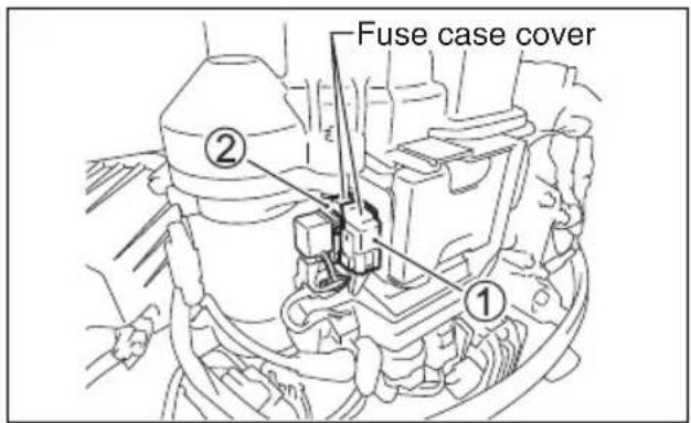
① Main fuse: 30A (white fuse case): All electric starter model
② ECM fuse: 10A (yellow fuse case): DF25AT/25AR/30AT/30AR
- Inspect the fuse and replace with the new fuse if needed.

NOTE:
If a fuse is blown, try to determine the root cause and correct it.
If the cause is not corrected, the fuse may be blown again.
WARNING
If you replace a blown fuse with a fuse having a different amperage rating or with a substitute such as aluminum foil or a wire, extensive electrical system damage and a fire may result.
Always replace a blown fuse with a fuse of the same type and rating.
NOTICE
If a new fuse blows in a short time after installation, you may have a major electrical system problem.
Consult your SUZUKI marine dealer.
SPECIFICATIONS
| Item DF25A DF30A | ||
| Engine Type 4 Stroke | ||
| Number of Cylinders 3 | ||
| Bore and Stroke 60.4 × 57.0 mm (2.38 × 2.24 in.) | ||
| Piston Displacement 490 cm | 3 (29.9 cu. in.) | |
| Maximum output 18.4 kW (25 PS) 22.1 kW (30 PS) | ||
| Full Throttle Operating Range 5000 – 6000 r/min. ( min-1 ) | 5300 – 6300 r/min. ( min-1 ) | |
| Ignition System Digital CDI | ||
| Engine Lubrication Trochoid pump pressure lubrication | ||
| Engine Oil Capacity 1.5 L (1.6/1.3 US/Imp. qt.) | ||
| Gear Oil Capacity 0.33 L (0.3/0.3 US/Imp. qt.) | ||
| Spark Plug | NGK MR6K-9 | |
| Spark Plug Gap | 0.8 – 0.9 mm (0.031 – 0.035 in.) | |
| Valve Clearance (Lash) | IN: 0.18 – 0.22 mm (0.007 – 0.009 in.)EX: 0.20 – 0.24 mm (0.008 – 0.009 in.) | |
| Fuel Type | Alcohol-free unleaded gasoline | |
| Minimum Fuel Octane Rating | 91 (Research method) | |
INFORMATION REGARDING EC - DIRECTIVE
(For European countries)
Sound Pressure Level
| Regulation | Sound pressure level limit |
| 2013 / 53 / EU | 72 dB (A) |
Sound pressure level is measured according to ISO 14509-1:2008.
Vibration on tiller handle grip
Tiller handle grip vibration total value of this motor measured under related EC Directive does not exceed 2.5m/s2 . The vibration measurement is performed specified in ISO 5349-1986.
FLOWCHART OF OIL CHANGE REMINDER SYSTEM
![graph TD A["Starting operation"] --> B{(*1) (*4)} B --> C["CancellationIndication"] C --> D{(*2) (*4)} D --> E["CancellationIndication"] E --> F{(*3) (*4)} F --> G["CancellationIndication"] G --> H{(*3) (*4)} H --> I["CancellationIndication"] I --> J["..."] J --> K["Repeat"] style A fill:#f9f,stroke…](/content/2026/06/1405538/images/c4404ae9ad277eb4f7ef8da5fc3df81d42accc7137f37d3e929d53f6e42b3823.jpg)
WIRING DIAGRAM
DF25A/30A/30AQ (ELECTRIC STARTER MODEL)
![graph TD A["MAP SENSOR"] --> B["MAGNET"] C["THROTTLE SENSOR"] --> D["CKP SENSOR"] E["IAC VALVE"] --> F["ENGINE CONTROL MODULE"] G["RECTIFIER & REGULATOR #1"] --> H["STARTING MOTOR M"] I["RECTIFIER & REGULATOR #2"] --> J["BATTERY"] K["STARTER RELAY"] --> L["FUSE 30A"] M["IAT SENSOR"] --> N["NEUTRAL S…](/content/2026/06/1405538/images/ab763029cf1427a45ec2a17001b9840f52d46a2efb26b7963b15955150269284.jpg)
DF25ATH/30ATH (POWER TRIM AND TILT MODEL)
![graph TD A["MAP SENSOR"] --> B["IAC VALVE"] C["THROTTLE SENSOR"] --> D["MAGNET"] E["FUEL INJECTOR"] --> F["CKP SENSOR"] G["HIGH PRESSURE FUEL PUMP"] --> H["FUEL INJECTOR"] I["ENGINE CONTROL MODULE"] --> J["CMP SENSOR"] K["STARTING MOTOR"] --> L["BATTERY"] M["SOSS"] --> N["SAMS"] O["NEUTRAL SWITCH"]…](/content/2026/06/1405538/images/3b55ce8b4ab92b777de625f63bef2ee2c66a9ae3fa52c8b31d9f89ff38425334.jpg)
---- Optional parts
Prepared by
SUZUKI MOTOR CORPORATION
October, 2018
Part No. 99011-94L60-055
Printed in Thailand
© COPYRIGHT SUZUKI MOTOR CORPORATION 2018


- WARNING
- CAUTION
- NOTICE
- NOTE
- IMPORTANT NOTICE TO OWNERS
- FOREWORD
- TABLE OF CONTENTS
- IDENTIFICATION NUMBER LOCATION
- FUEL AND OIL
- GASOLINE
- GASOLINE/ETHANOL BLENDS
- PUMP LABELING FOR GASOLINE/ALCOHOL BLENDS
- ENGINE OIL
- GEAR OIL
- EXTREMELY FLAMMABLE
- DANGER
- LOCATION OF PARTS
- TILLER HANDLE MODEL (DF25A/30A)
- TILLER HANDLE MODEL (DF30AQ)
- TILLER HANDLE MODEL (DF25ATH/30ATH)
- MOTOR MOUNTING
- TILLER HANDLE MODEL
- REMOTE CONTROL MODEL
- BATTERY INSTALLATION
- BATTERY REQUIREMENT ELECTRIC STARTER MODEL
- USE OF ELECTRICAL ACCESSORIES
- PROPELLER SELECTION AND INSTALLATION
- PROPELLER SELECTION
- PROPELLER INSTALLATION
- ADJUSTMENT
- TRIM ANGLE ADJUSTMENT
- DF25A/25AR/30A/30AR
- DF30AQ
- DF25AT/25ATH/30AT/30ATH
- TRIM TAB ADJUSTMENT
- TO ADJUST THE TRIM TAB
- STEERING TENSION ADJUSTMENT
- THROTTLE TENSION ADJUSTMENT TILLER HANDLE MODEL
- IDLE SPEED ADJUSTMENT
- CAUTION SYSTEM
- CAUTION LAMP CHECK
- OVER-REVOLUTION CAUTION SYSTEM
- OIL PRESSURE CAUTION SYSTEM
- OVERHEAT CAUTION SYSTEM
- DIAGNOSTIC SYSTEM
- OIL CHANGE REMINDER SYSTEM
- SYSTEM ACTIVATION
- CANCELLATION
- ENGINE STALLING CAUTION SYSTEM
- LOCK" POSITION
- RELEASE" POSITION
- TILT UP LOCK ARM
- SHALLOW WATER POSITION
- MANUAL TILTING
- TILT LOCK LEVER
- INSPECTION BEFORE BOATING
- BREAK-IN
- BREAK-IN PROCEDURE
- OPERATION
- BEFORE ATTEMPTING TO START THE ENGINE
- STARTING THE ENGINE
- RECOIL STARTER MODEL
- COOLING WATER CHECK
- EMERGENCY STARTING
- TO START THE ENGINE WHEN THE RECOIL STARTER FAILS
- SHIFTING AND SPEED CONTROL
- TILLER HANDLE MODEL SHIFTING
- SPEED CONTROL
- REMOTE CONTROL MODEL SHIFTING
- STOPPING THE ENGINE
- MOORING
- OPERATION IN SHALLOW WATER (DF25A/25AR/30A/30AR)
- OPERATION IN SHALLOW WATER (DF30AQ)
- OPERATION IN SHALLOW WATER (DF25AT/25ATH/30AT/30ATH)
- OPERATION IN SALT WATER
- MOTOR REMOVAL AND TRANSPORTING
- MOTOR REMOVAL TILLER HANDLE MODEL
- MOTOR TRANSPORTING
- VERTICAL TRANSPORT
- HORIZONTAL TRANSPORT
- TRAILERING
- INSPECTION AND MAINTENANCE
- MAINTENANCE SCHEDULE
- TOOL KIT
- SPARK PLUG
- BREATHER AND FUEL LINE
- ENGINE OIL CHANGE
- LUBRICATION
- ANODES
- BONDING WIRE
- BATTERY
- ENGINE OIL FILTER
- FUEL FILTER
- LOW PRESSURE FUEL FILTER
- LOW PRESSURE FUEL PUMP FILTER
- TIMING BELT
- AIR CLEANER ELEMENT
- FLUSHING THE WATER PASSAGES
- ENGINE RUNNING – VERTICAL POSITION
- ENGINE NOT RUNNING
- VERTICAL POSITION
- FULL TILT UP POSITION
- SUBMERGED MOTOR
- STORAGE PROCEDURE
- MOTOR STORAGE
- BATTERY STORAGE
- ELECTRIC STARTER MODEL
- AFTER STORAGE
- TROUBLESHOOTING
- RECOIL STARTER/STARTER MOTOR WILL NOT OPERATE
- ENGINE WILL NOT START (HARD TO START)
- ENGINE IDLES UNSTABLY OR STALLS
- ENGINE SPEED WILL NOT INCREASE (ENGINE POWER IS LOW)
- ENGINE VIBRATES EXCESSIVELY
- ENGINE OVERHEATS
- FUSE
- INFORMATION REGARDING EC - DIRECTIVE
- VIBRATION ON TILLER HANDLE GRIP
- FLOWCHART OF OIL CHANGE REMINDER SYSTEM
- WIRING DIAGRAM
- SUZUKI MOTOR CORPORATION
Brand : SUZUKI
Model : DF25A
Category : Outboard motor