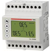
ADR-D Out - Analyseur réseau Vemer - Free user manual and instructions
Find the device manual for free ADR-D Out Vemer in PDF.


| Product Type | Digital Temperature Controller |
| Model | ADR-D Out |
| Brand | Vemer |
| Dimensions (HxWxD) | 85 x 85 x 30 mm |
| Weight | 0.1 kg |
| Power Supply | 230 V AC 50/60 Hz |
| Power Consumption | < 3 W |
| Display Type | LCD with backlight |
| Temperature Range | -10°C to 50°C |
| Control Type | PID / On-Off |
| Output Type | Relay 5 A |
| Sensor Type | NTC 10kΩ @ 25°C |
| Protection Rating | IP20 |
| Operating Temperature | 0°C to 50°C |
| Storage Temperature | -20°C to 60°C |
| Main Functions | Temperature control, heating/cooling, setpoint adjustment, hysteresis, calibration |
| Cleaning and Maintenance | Wipe with a dry, soft cloth. Do not use solvents or water. |
| Safety Features | Overheat protection, sensor failure alarm |
| Spare Parts and Repairability | No user-serviceable parts. Contact Vemer support for repairs. |
| Documentation | User manual available for free download |
Frequently Asked Questions - ADR-D Out Vemer
User questions about ADR-D Out Vemer
0 question about this device. Answer the ones you know or ask your own.
Ask a new question about this device
Download the instructions for your Analyseur réseau in PDF format for free! Find your manual ADR-D Out - Vemer and take your electronic device back in hand. On this page are published all the documents necessary for the use of your device. ADR-D Out by Vemer.
USER MANUAL ADR-D Out Vemer
■ Safety warnings Page 30
■ Technical specifications Page 30
■ Description of instrument Page 31
■ Keys Page 32
■ Setting the parameters Page 32
■ Displaying the measurement pages Page 39
■ Measurement and calculation method Page 49
■ Reference standards Page 50
■ ADR-R out dimensions and connection diagrams Page 24-25
■ ADR-D out dimensions and connection diagrams Page 26-27
SAFETY WARNINGS
■ During the installation and operation of the instrument, the following should be noted:
1) The instrument should be installed by a competent person
2) Follow the connection diagrams to the letter when installing the instrument
3) When connecting the instrument, always use the TA x/5 A
4) The appliance should be installed in a panel where the terminals will be inaccessible after installation
5) The voltage and current circuit terminals may be connected with a maximum rated voltage of 300 V eff. with respect to earth
6) The panel should be wired in line with the relevant CEI standards
7) Do not power or connect the instrument if any part of it is damaged
NOTE:
- The VEMER network analysers are designed for use in environments with over-voltage category III and pollution level 2, in accordance with the CEI-EN 61010-I standard.
- The electrical system of the building where the instrument is to be installed should contain a switch or isolator. This should be close to the instrument and within easy reach of an operator. An over-current protection device should be fitted.
Important: when the power supply is cut off, there should be no signal at the measurement inputs (current or voltage).
TECHNICAL SPECIFICATIONS
• P o wer supply: 230 VAC (-15%/+10%)
• F frequency: 50/60 Hz
• Maximum consumption: 5 VA
- Display: rear-lit LCD
• V oltmeter inputs: max 500 VAC, 47÷63Hz (phase-phase concatenated)
- Ammeter inputs: max 6 A, 47÷63 Hz
- Scales: 1 voltage with end of scale 500 V (phase-phase concatenated)
2 current with end of scale at 1.25 A and 6 A
- Precision:
- Voltage: 0.5% of the end of scale value (min 10 V)
- Current: 0,5% of the end of scale value (min. 20 mA)
- P o wer: 1% of the end of scale value
- F frequency: ±0,1 Hz (47÷63 Hz)
- Active energy CEI-EN 61036 class 2
- Reactive energy CEI-EN 61268 class 3
• TV available: primary 1÷9999 V +10÷65kV; secondary 230 V
• T A available: primary 1÷9999 A; secondary 5 A
• 2 x 250 VAC 2 A relay outputs (105 x VDE0435 operations)
- Operating temperature: 0 ÷ +50^ C
- Relative humidity: 10% ÷ 90% non-condensing
- Containers:
- Rear panel version: material in class V0 in accordance with the UL 94 standard, standard dimensions 72 × 72 ~mm in accordance with the DIN 43700 standard
- Modular version: material in class V0 in accordance with the UL 94 standard, 4 DIN module containers, colour RAL-7035 grey
Network analyser
Code ModelDescription
VN794400 ADR-R-outNetwork analyser with relay output, rear panel version
VN795100 ADR-D-outNetwork analyser with relay output, modular version
DESCRIPTION OF INSTRUMENT
Display

- ① Numerical fields for the display of the values measured
- ② Type of measurement taking place
- ③ Measurement unit
- ④ Phase symbols
KEYS

Scroll to the next page and parameter setting

Scroll to the previous page and parameter setting

Display of the system values

Display of the peak values to be measured and selection of the parameters in the programming stage
SETTING THE PARAMETERS
First installation programming
■ To gain access to the first installation programming menu, the instrument has to be powered by holding down the "up" (▲) and "down" (▼) keys together until the display is lit up
■ The parameters that can be programmed by the user are the following, in order:
• Primary TV (fixed secondary 230 V)
• Primary TA (fixed secondary 5 A)
For a new parameter setting, the instrument should be switched off then on again by holding down the "up" (▲) and "down" (▼) keys together until the display is lit up
Important: before switching the instrument off, disconnect the measurement (current and voltage)
TV setting
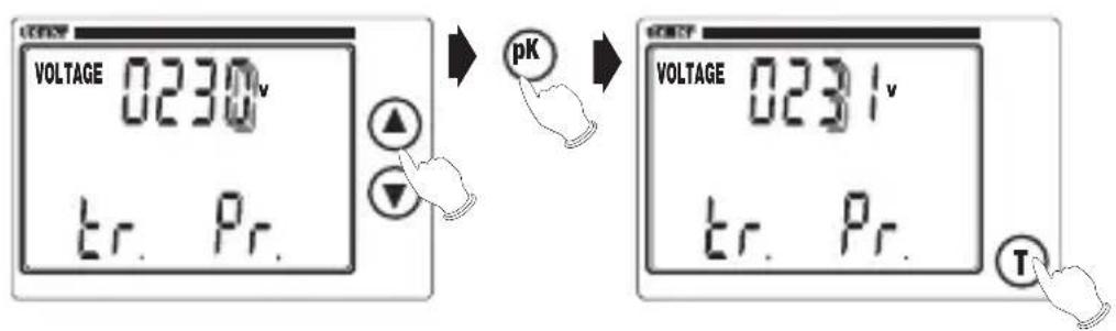
- Press the "up" (▲) or "down" (▼) keys to select the required value of the
flashing digit or prefix "k" (flashing = deactivated, fixed = active)
• T o go to the next digit, press "pK"
- T o confirm the value set and go to the next window, press "T"
TA setting

- Same procedure as TV setting
Note: for the primaries of the TV and TA, any value between 0001 and 9999 may be set. The secondaries are set to 230V and 5A respectively. For the TV primary, it is also possible to set a value between 10kV and 65kV.
■ When “T” is pressed, all the symbols of the display will come on for approximately 3 seconds, followed by the display of the output relay status page.
Note: if the power is cut off during programming, the instrument will memorise all the settings up to the moment when this occurs.
Programming in normal operation
■ Access to the programming menu in normal operation is gained by holding the "pK" key down for approximately 3 seconds.
■ The parameters that can be set by the user are the following, in order:
- D a te/time
- Relay output 1 programming (see page 8)
- Relay output 2 programming (see page 8)
- Integration time for the calculation of the integral mean of the power ratings
• Display rear lighting management
• Zeroing of active energy meters
• Zeroing of reactive energy meters - Zeroing of peaks
- Change of protection password
■ Press the “up” (▲) or “down” (▼) keys to scroll through the setting menus Press “T” from the end menu to leave the programming (this takes place automatically if no key is pressed for approximately 60 seconds)
■ Before entering the programming menu, the user is asked to enter the password (default "0000"). If an incorrect password is entered, the parameters will be displayed but it will not be possible to modify them.
Setting the date and time

- Press T from the "Time" menu to enter the time and date setting page
- Press the “up” (▲) or “down” (▼) keys to select the value of the flashing digit required
- Press "pK" to go to the next digit
- Press "T" to return to the main programming page
Setting the integration time

- Press T from the "Average" menu to enter the mean power rating integration time setting page
- Press the “up” (▲) or “down” (▼) keys to select the value of the integration time required
- It is possible to set an integration time from a minimum of 1' to a maximum of 60' (the default value is 15')
- Press "T" to return to the main programming page
Rear lighting management
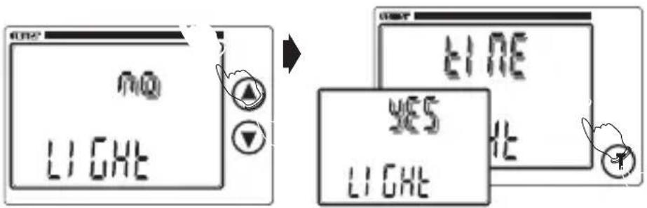
- Press T from the "Light" menu to enter the rear lighting setting page
- Press the "up" (▲) or "down" (▼) keys to select one of the options "NO" (rear lighting deactivated), "YES" (activated) or "TIME" (activated for approximately 60 seconds after a key is pressed)
- Press "T" to return to the main programming page
Zeroing the active/reactive energy and peak meters

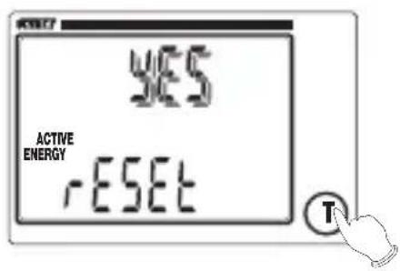
- Press T from the "Reset" menu to enter the active energy reset page
- Press the "up" (▲) or "down" (▼) keys to select one of the options "YES" (active energy zeroing) or "NO"
- T o confirm the value set and go to the next window, press "T"
- The same procedure is then used to zero the reactive energy and peak meters
- Press "T" to return to the main programming page
Changing the password

- Press T from the "Code" menu to enter the password setting page
- Press the "up" (▲) or "down" (▼) keys to select the first digit (flashing)
- Press "pK" to go to the next digit
- Press "T" to save the password and return to the main programming menu
Note: if you forget the password entered, the default password ("0000") can be reset by resetting the instrument (this may also occur accidentally if the power is cut off)
Relay programming
■ From the relay 1 (or 2) menu in normal programming, press “T” to gain access to the relay 1 (2) programming menu
■ The parameters that can be set by the user are the following, in order:
- Operating value
- Latching
- Alarm mode
- Relay operating mode
- Set-point value
- Differential value
- Relay activation delay
■ Press "T" to go from one menu to the next
Press T from the "Delay" menu to return to the relay 1 (or 2) menu
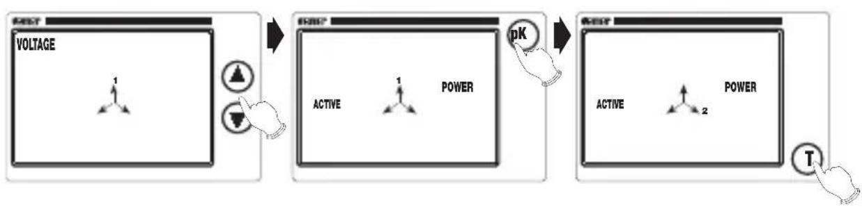
flowchart
graph LR
    A["VOLTAGE"] --> B["1"]
    B --> C["Power"]
    C --> D["pK"]
    D --> E["Active"]
    E --> F["2"]
    F --> G["T"]
- Press the “up” (▲) or “down” (▼) keys to select the value for which the relay is to intervene.
The values that can be selected are as follows, in order: voltage, current, active power, apparent power, reactive power, cos w, mean active power, mean apparent power, mean reactive power, active energy and concatenated voltage
- Press "pK" to select the phase (where possible)
The absence of the phase symbol at the centre of the display indicates the system value
- Press "T" to confirm the value set


- Press "up" (▲) or "down" (▼) to activate or deactivate "Latching" mode (maintenance of the alarm condition until a key is pressed), and confirm with "T"
- When “Latching” mode is enabled, the display will go to the measurement page for the value that has activated the relay (flashing) when the conditions that generated the alarm are removed


- Select the maximum alarm mode "Hi" or the minimum "Lo" with the "up" (▲) or "down" (▼) keys and confirm with "T"
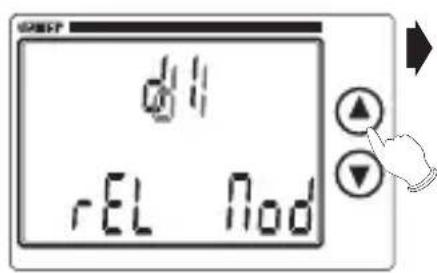
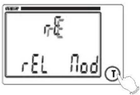
- Select the relay operating mode (direct "dl" or reverse "rE") with the "up" (▲) or "down" (▼) key and confirm with "T"

- Set the set-point value for the measurement selected (visible on the display display). Use the "up" (▲) or "down" (▼) keys to set the flashing digit and "pK" to go to the next digit.
Press "T" to confirm

- Set the differential value (hysteresis) with the same procedure as that for the set-point
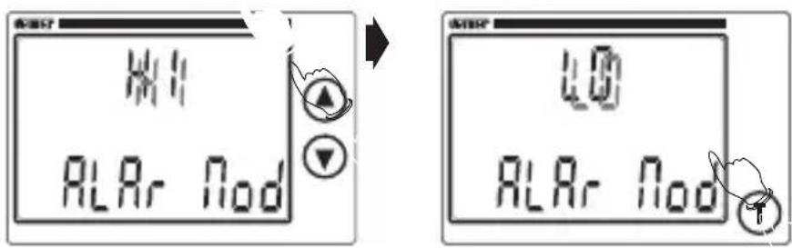
- Set the relay activation delay value (in seconds) with the same procedure as that for the set-point
Note: if the energy operation is selected (active for relay 1 or reactive for relay 2), the set-up movements from latching mode onwards will not be displayed, as they serve no purpose In this case, the relays will not operate as alarms, but as consumption indicators for active/reactive energy
- A window will then be displayed for the setting of the energy value corresponding to each impulse

- Press the "up" (▲) or "down" (▼) keys to select the value of the flashing digit and pK to go to the next digit
-
By default, the weight of the impulse (set on calibration and on each modification of the TA/TV) is equivalent to:
-
1 impulse every "20 x value primary TA" Wh/varh, for primary TV up to 230 V
- 1 impulse every "40 x value primary TA" Wh/varh, for primary TV from 230 to 580 V
- for the primary TV over 580 V, the impulse output is inactive These are the minimum values that can be set for the impulse weight The duration of the impulse is always constant and equivalent to 100ms
DISPLAYING THE MEASUREMENT PAGES
■ When the instrument is switched on (or after the programming stage), the first page (relay status) is displayed after approximately 3 seconds with the display completely on
■ When the “up” key (▲) is pressed from the first page, all the other measurement pages are displayed in sequence. Press the “up” key (▲) from the last page to return to the main page.
Note: in the event of incorrect entry (current polarity inverted or no correspondence between phase voltage and current), the phases involved are highlighted and the number for the group of symbols at the centre of the display is cancelled.
1) Relay status page

- The status of the two relays is displayed ("ON" or "OFF")
1b) Relay switching page

- Press the "pK" repeatedly from the relay status page to display the following, in order:
- the instant when the last switching operation took place on the relay indicated (press "T" to move from one relay to another), expressed in time and date
- the number of hours that has lapsed from the last reset of the instrument and the switching operation, expressed in hours and tenths of an hour
- Press the "up" key (▲) at any time to go to the next page
Note: when “pK” and “T” are pressed and held down together for 3 seconds, the switching of both relays is forced for approximately 30 seconds (or a 100 ms impulse is forced if the relays are set as “consumption indicators”). This status is confirmed by the complete lighting up of the central symbol in the display.
2) Overall page
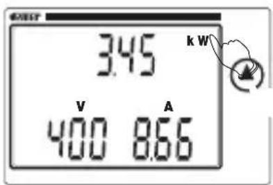
- The system voltage and current and the active system power rating are displayed
- Press "pK" to display the value set for the TA primary. Press "T" to display the value set for the TV primary
Note: if the voltage V or the current I are >999, the words “Voltage” and/or “Current” will flash to indicate that the measurement unit is not complete (the prefixes 'k' or 'M' are missing)
3) Phase voltage page
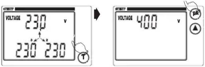
• The phase voltages are displayed.
If the three phase system has no neutral, the voltages refer to a fictitious star delta centre
- Press "T" to display the system voltage page
3a) Phase voltage peak value page

- If the "pK" is pressed repeatedly from one of the two phase voltage pages, the following are displayed in order:
- the voltage peak values (phase or system), with the "V" measurement unit flashing
- the instant when the peak occurred (time and date flashing if the clock has not yet been set)
- the number of hours lapsed between the start-up of the instrument and the occurrence of the peak, in hours and tenths of one hour
- Press "up" (▲) at any time to go to the next page
4) Concatenated voltage page

• The voltages concatenated between the phases are displayed
5) Phase current page


• The phase currents are displayed
- Press "T" to display the system current
5a) Phase current peak value pages


- The same procedure as the display of the phase voltage peak values
6) Active phase power rating page
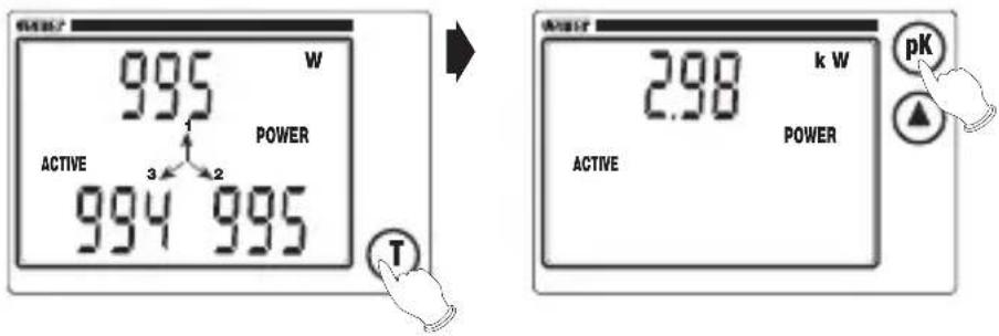
• The active phase power ratings are displayed
- Press "T" to display the active system power rating
6a) Active power rating peak value page
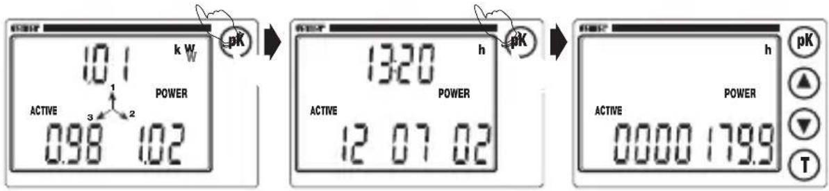
- The same procedure as the display of the phase voltage peak values
7) Apparent phase power rating page

• The apparent phase power rating values are displayed
- Press "T" to display the apparent system power rating
7a) Apparent peak value pages

- The same procedure as the display of the phase voltage peak values
8) Reactive phase power rating page

• The reactive phase power ratings are displayed
- Press "T" to display the reactive system power rating
8a) Reactive power peak value page
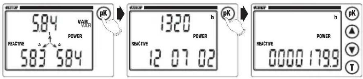
- The same procedure as the display of the phase voltage peak values
9) Phase power factor page
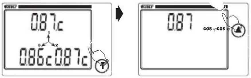
- The phase power factors are displayed (the letter "C" indicates a capacity phase shift and the letter "L" an inductive phase shift)
- Press "T" to display the system power factor
10) Voltage-current phase shift page

- The voltage-current phase shifts are displayed in sixtieth degrees (the letter "C" indicates a capacity phase shift and the letter "L" an inductive phase shift)
11) Mean active system power rating page

- The active system power rating is displayed over a mean of N minutes (can be set from 1 to 60) The default value is 15 min
11a) Mean active power rating peak value page

- The same procedure as the display of the phase voltage peak values
12) Mean apparent system power rating page
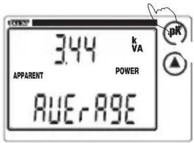
- The apparent system power rating is displayed over a mean of N minutes (can be set from 1 to 60) The default value is 15 min
12a) Apparent mean power rating peak value page
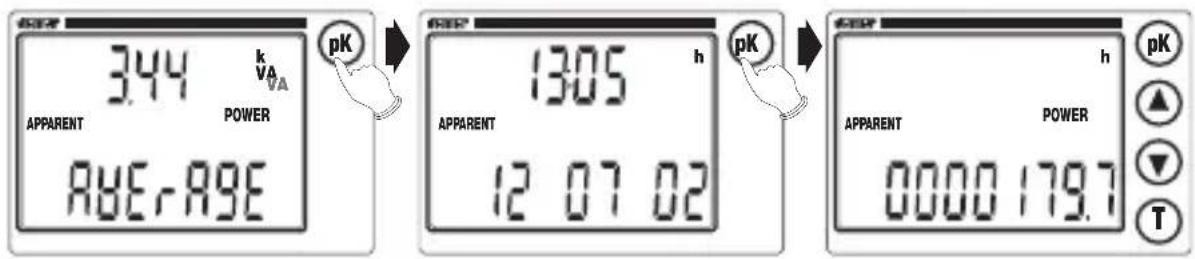
- The same procedure as the display of the phase voltage peak values
13) Mean reactive system power rating page
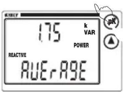
- The reactive system power rating is displayed over a mean of N minutes (can be set from 1 to 60) The default value is 15 min
13a) Mean reactive power rating peak value page

- The same procedure as the display of the phase voltage peak values
Note: If the “pK” and “T” keys are held down together for three seconds from display pages 11, 12 and 13, the integration of the mean active, reactive and apparent power ratings is obtained.
The central symbols in the display flash to confirm this operation, which can be used to synchronise the calculation of the power rating with the power supply company, such as ENEL, for example.
14) Total active energy page

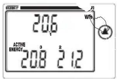
• The total active energy is displayed
- Press “T” to display the partial active energy ratings for the single phases (these energy ratings are zeroed each time the total active energy is increased)
14a) Total absolute active energy page


- If the "pK" key is pressed from the total active energy page, the value of the absolute active energy is displayed, with the symbol "AbS". This value cannot be zeroed, except due to meter overflow at 9999999.9kWh.
15) Total reactive energy page

• The total reactive energy is displayed
- Press "T" to display the partial reactive energy ratings for the single phases (these energy ratings are zeroed each time the total reactive energy is increased)
15a) Total absolute reactive energy page

- If the “pK” key is pressed from the total reactive energy page, the value of the absolute reactive energy is displayed, with the symbol “AbS”. This value cannot be zeroed, except due to meter overflow at 9999999.9 kvarh).
16) Frequency page

• The frequency of voltage V1 is displayed
17) Time and date page


- The time and date are displayed in dd-mm-yy format
- Press "pK" to display the time lapsed from the start-up of the instrument, expressed in hours and tenths of an hour
- Press "up" (▲) to return to the starting page
Note: from the first setting onwards, the time and date will flash. These will also flash in the peak value pages.
MEASUREMENT/CALCULATION METHOD
- The voltage and current measurements are taken in TRMS (True RMS) by means of sampling and analogue-digital conversion.
- The following formulas are used to calculate the system values:
System voltage V =
$$ \frac {V _ {1} + V _ {2} + V _ {3}}{\sqrt {3}} $$
System current I =
$$ \frac {\mathrm{l} _ {1} + \mathrm{l} _ {2} + \mathrm{l} _ {3}}{\sqrt {3}} $$
Active system power P = P
$$ 1 ^ {+ P} 2 ^ {+ P} 3 $$
Reactive system power Q = Q
1^+Q 2^+Q_3 (algebraic sum)
Apparent system power
$$ \mathbf {A} = \sqrt {\mathbf {P} ^ {2} + \mathbf {Q} ^ {2}} $$
System power factor
$$ \mathbf {P F} = \frac {\mathbf {P}}{\mathbf {A}} $$
Total reactive energy
$$ \mathbf {E} = \mathrm{E} _ {1} + \mathrm{E} _ {2} + \mathrm{E} _ {3} $$
Mean active system power Er = Er
$$ 1 + \mathrm{Er} _ {2} + \mathrm{Er} _ {3} $$
Mean active system power
$$ \mathbf {P} _ {\text { Avg }} = \frac {1 ^ {0}}{\mathbf {T} _ {- T}} \int \mathbf {P d t} (T = 1 ^ {\prime} \div 6 0 ^ {\prime} \text { programme }) $$
Mean system Q Q
$$ \mathbf {A} \mathbf {v g} = \frac {\mathbf {1} ^ {0}}{\mathbf {T} _ {- T}} \int \mathbf {Q} \mathbf {d t} (T = 1 ^ {\prime} \div 6 0 ^ {\prime} \text { programme }) $$
Mean system A A
$$ \mathbf {A} \mathbf {v g} = \frac {\mathbf {1} ^ {0}}{\mathbf {T} _ {- T}} \int \mathbf {A} \mathbf {d t} (T = 1 ^ {\prime} \div 6 0 ^ {\prime} \text { programme }) $$
REFERENCE STANDARDS
■ Conformity to EU directives:
73/23/EEC modified by 93/68/EEC (safety)
89/336/EEC modified by 92/31/EEC and 93/68/EEC (EMC)
is declared with reference to the following harmonised standards:
Safety:
CEI-EN 61010-1: Safety provisions for electrical measurement, control and laboratory appliances;
Part I: general provisions
■ Electromagnetic compatibility:
CEI-EN 50082-2: General standard on equipment in an industrial environment CEI-EN 50081-1: General standard on emissions in household, commercial and light industrial environments
■ Measurement provisions:
CEI-EN 61036: Static active energy electricity meters for AC (classes 1 and 2) CEI-EN 61268: Static reactive energy electricity meters for AC (classes 2 and 3)
- SAFETY WARNINGS
- ■ During the installation and operation of the instrument, the following should be noted:
- NOTE:
- TECHNICAL SPECIFICATIONS
- Network analyser
- Code ModelDescription
- DESCRIPTION OF INSTRUMENT
- Display
- KEYS
- SETTING THE PARAMETERS
- First installation programming
- Important: before switching the instrument off, disconnect the measurement (current and voltage)
- TV setting
- TA setting
- Programming in normal operation
- Setting the date and time
- Setting the integration time
- Rear lighting management
- Zeroing the active/reactive energy and peak meters
- Changing the password
- Relay programming
- DISPLAYING THE MEASUREMENT PAGES
- 1) Relay status page
- 1b) Relay switching page
- 2) Overall page
- 3) Phase voltage page
- 3a) Phase voltage peak value page
- 4) Concatenated voltage page
- 5) Phase current page
- 5a) Phase current peak value pages
- 6) Active phase power rating page
- 6a) Active power rating peak value page
- 7) Apparent phase power rating page
- 7a) Apparent peak value pages
- 8) Reactive phase power rating page
- 8a) Reactive power peak value page
- 9) Phase power factor page
- 10) Voltage-current phase shift page
- 11) Mean active system power rating page
- 11a) Mean active power rating peak value page
- 12) Mean apparent system power rating page
- 12a) Apparent mean power rating peak value page
- 13) Mean reactive system power rating page
- 13a) Mean reactive power rating peak value page
- 14) Total active energy page
- 14a) Total absolute active energy page
- 15) Total reactive energy page
- 15a) Total absolute reactive energy page
- 16) Frequency page
- 17) Time and date page
- MEASUREMENT/CALCULATION METHOD
- REFERENCE STANDARDS
Brand : Vemer
Model : ADR-D Out
Category : Analyseur réseau