
Cala - Temperature Controller ASTRALPOOL - Free user manual and instructions
Find the device manual for free Cala ASTRALPOOL in PDF.


| Product Type | Temperature Controller |
| Brand | AstralPool |
| Model | Cala |
| Dimensions (approx) | 150 x 80 x 40 mm |
| Weight (approx) | 0.5 kg |
| Power Supply | 12V DC, 1A |
| Display Type | LCD |
| Temperature Range | 5°C - 40°C |
| Temperature Accuracy | ±0.5°C |
| Main Functions | Precise temperature control, programmable timer, manual override |
| Control Interface | Touch buttons |
| Protection Rating | IP44 (splash-proof) |
| Housing Material | ABS plastic |
| Maintenance | Clean with damp cloth; avoid solvents |
| Safety Features | Overheat protection, short circuit protection |
| Spare Parts Availability | Available from AstralPool distributors |
| Reparability | Repairable by qualified technician; replaceable fuses |
| Warranty | 2 years |
| Compatible Systems | AstralPool pumps and heaters |
Frequently Asked Questions - Cala ASTRALPOOL
User questions about Cala ASTRALPOOL
0 question about this device. Answer the ones you know or ask your own.
Ask a new question about this device
Download the instructions for your Temperature Controller in PDF format for free! Find your manual Cala - ASTRALPOOL and take your electronic device back in hand. On this page are published all the documents necessary for the use of your device. Cala by ASTRALPOOL.
USER MANUAL Cala ASTRALPOOL
natural_image
Interior view of a minimalist minimalist room with curved ceiling lighting and small white geometric blocks on the floor (no text or symbols visible)CONTENTS
Steam bath installation guide.... 1
Construction of the cabin and pre-construction installations.... 6
Custom built cabin
Construction system for the steam bath.... 7
Advantages of the prefabricated ceiling 8
Installation of the prefabricated ceiling 8
Graphic guide for the installation of the prefabricated modules. 9
Graphic guide for the installation of the ceiling modules 10
Prefabricated cabin
Advantages of the prefabricated cabin compared to a custom built cabin.... 12
Material and basic components of the steam cabin.... 12
Horizontal section of the prefabricated cabin.... 13
Vertical section of the prefabricated cabin 13
Construction detail and anchoring of the steam bath.... 14
Available models. Capacity and laout.... 15
Assembly and installation process.... 16
Assembly of the cabin.... 16
Procedure for installing the steam cabin.... 17
Control panel
Function keys.... 22
General operation.... 22
Troubleshooting.... 24
Troubleshooting guide.... 25
Maintenance guide.... 28
Steam bath rules for use
Contradictions.... 30
Specific considerations 30
Cleaning and disinfecting the aroma oil system 31
Required power of the generator with regard to cabin size.... 31
Sections and protections for electric cables.... 32
Ecotouch electrical diagram.... 33
STEAM BATH INSTALLATION GUIDE
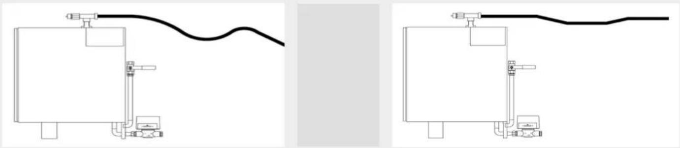
- The steam pipe must not have any pronounced bends or elbows.
- The steam pipe must not have any siphons where condensed water may collect and lead to a blockage.
- Steam baths that are used for more than one hour continuously must have air vents installed.
- The steam generator must not be cut off from the electricity supply, therefore timer switches or other similar devices may not be installed.
- The length of the drainpipe must slope down towards to the downpipe.
- The ambient temperature outside the steam cabin must not be more than 35 degrees.
- The temperature probe must be placed as far away as possible from the steam outlet.
- A water analysis must be carried out before starting up the equipment. If the water hardness is more than 4 French degrees, a water softener must be installed.
- Do not install the steam equipment without a ground connection.
Location of the generator:
The following requirements are necessary for the generator's location:
-
A room that is no smaller than 80 cm wide, 50 cm deep and 170 cm high.
-
The room where it is installed must be dry and well-ventilated.
-
Do not install in machinery rooms where corrosive products such as chlorine are used.
-
The equipment must be installed outside the steam cabin, but as close as possible to it. The steam pipe must not be more than 15 metres long.
-
The equipment must be installed perfectly vertical.
-
The equipment must rest on the ground and be fixed to the wall using 4.5 x 60 mm plastic wall plugs and stainless steel screws. Before fixing the equipment in place, ensure that the drain outlet is higher than the connection designed for it, so that the generator can be emptied correctly.
Connection to power supply: When connecting the electricity supply, first connect the ground wire followed by the active wires to the differential switch inside the steam generator. Connection must be made taking into consideration the type of power supply (page 15). On page 32 the recommended cable section and associated protection is given, according to the size of the generator. Cables must be copper, RZ1-K (AS) safety and protected by a differential switch or circuit breaker with an opening that guarantees a minimum separation of contacts of 3 mm. In all cases, the electrician is responsible for the installation according to the Low Voltage Electrotechnical Regulations.
Once completed turn on the switch to the right, the pilot light will come on, meaning that the generator is connected to the power supply. If the wires must be disconnected, first of all disconnect the active wires and subsequently the ground connection.
The generator must, without fail, be grounded. If it is not connected to earth, electrical accidents may occur. The power supply must not be cut-off or the side switch turned off before two hours after the steam supply to the cabin has been switched off because the generator drains the system various times during this period to prevent the accumulation of mineral salts in the boiler. Therefore, timers must not be installed as these may cut off the power supply.
Connection to water supply: The steam generator has a 12 inch shut off valve for the water supply. This can be connected to the cold water supply. The water pressure must be between 2 and 6 kp/cm ^2 . Before starting up the generator the pipes must be flushed out to prevent metal residues from being introduced into the generator's boiler tank. Before starting up the generator, an analysis of the water must be carried out to determine its hardness. If it is above 4 French degrees a water softener must be installed.
Connection to drain: The pipes must be installed with a slope towards the downpipe, with no siphons where water can accumulate.
Connection of light fixture: A light fixture with a 24 volt bulb is supplied with the equipment for lighting inside the cabin.
Connection of temperature probe: The sensor must be placed between 150 and 170 cm from the floor and as far as possible from the steam outlet. A trim cover is supplied with the equipment to cover the sensor. It must be placed vertically so that the air can circulate around it. If there is a gap between the sensor and the cabin, the cable can be lengthened using a low voltage armoured two core cable.
Connection of steam pipe to the cabin: A 22 mm copper or stainless steel pipe must be used for the steam line. Generators with more than 12 kW of power have 2 or more steam lines, therefore as many lines as generators must be connected to the steam cabin. Warning: Do not connect two generator outlets to one line as the pressure and the correct temperature of the generators may be exceeded. The steam lines must not have siphons where condensed water could block the steam's path.
Incorrect installation:
natural_image
Two schematic diagrams of industrial piping and valves, showing different connection configurations (no text or labels)Incorrect installation: Correct installation:

natural_image
Three black L-shaped lines on a white background, no text or symbols presentIn cases where the generator is on the same floor as the cabin, the steam line must be installed sloping towards the cabin. If it is on a lower floor it must slope towards the generator.
The steam lines must be insulated with armaflex or similar, to prevent them from cooling and from condensation building up inside the pipe.
No mechanisms should be installed along the steam line that may block the circulation of the steam, including pressure or flow controllers, shut off valves, pipe reducers, etc.
The generator is supplied with a steam head. This is used for fixing the line to the cabin and for directing the steam towards the floor.

natural_image
Technical line drawings of two structural components with hatched patterns and a central rod, shown from different angles (no text or symbols)One of the most important points of the installation is the location of the steam head. Take into account that the steam comes out of the head at a temperature of 100 degrees. Therefore it is essential that they are positioned where they will not cause any harm to users. A ventilator and a PVC pipe are supplied with the equipment for ventilating the cabin. Wherever possible the air inlet should be placed above the steam head, this way cooling the steam at the outlet of the head.
Following, different correct installation options for the steam head are shown.

Option A Options B AND C Option D


Where Option A is selected but there is not a 50 cm gap between the outlet and the bench an optional accessory can be ordered, called a steam diffuser.
This is a stainless steel protector, with a cooling chamber, to prevent users from burning themselves.

natural_image
White cylindrical shower unit placed on a tiled wall, no visible text or symbolsConnection of the air ventilator: The generator is supplied with an inlet ventilator, with the necessary pipes for installation, according to the previous diagrams. This ventilator must be connected to the generator using a 3 x 1.5 mm core cable.
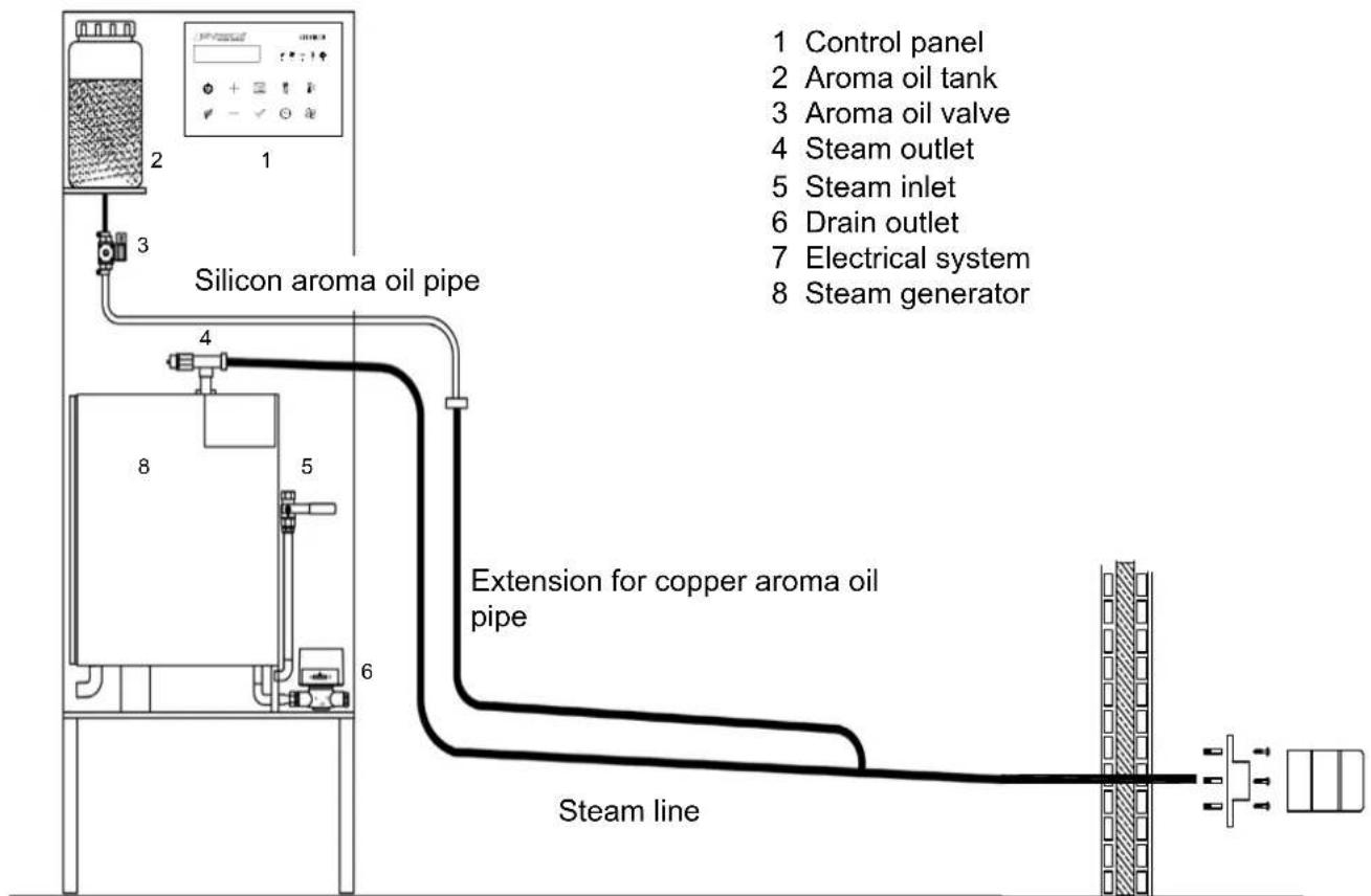
Connection of the aroma oil system to the generator on the same floor as the cabin: The equipment necessary for mixing the aroma oil with the steam are supplied with the generator. For the aroma oil system to operate correctly, the aroma oil pipe and the steam pipe must be connected over half the distance between the generator and the steam cabin. For example, if the steam line is 8 metres long, a copper pipe that is more than 4 metres long must be installed parallel to it before the connection. If this is not done correctly the aroma oil will not enter the steam line due to the pressure inside it.
flowchart
graph TD
    A["Control panel"] --> B["Silicon aroma oil pipe"]
    C["Aroma oil tank"] --> B
    D["Aroma oil valve"] --> B
    E["Steam outlet"] --> B
    F["Steam inlet"] --> B
    G["Drain outlet"] --> B
    H["Electrical system"] --> B
    I["Steam generator"] --> B
    B --> J["Extension for copper aroma oil pipe"]
    J --> K["Steam line"]
    style A fill:#f9f,stroke:#333
    style C fill:#f9f,stroke:#333
    style D fill:#f9f,stroke:#333
    style E fill:#f9f,stroke:#333
    style F fill:#f9f,stroke:#333
    style G fill:#f9f,stroke:#333
    style H fill:#f9f,stroke:#333
    style I fill:#f9f,stroke:#333
Connection of the aroma oil system to the generator on a floor below the cabin: If the steam generator is installed on a floor below the cabin, the aroma oil system is equipped with a pump so that the aroma oil travels up to the steam cabin. In order for the system to operate correctly, a copper pipe must be installed parallel to the steam line until the cabin inlet slope, so that the aroma oil does not drip back down into the generator through the steam line.

flowchart
graph TD
    A["15 mm copper aroma oil pipe"] --> B["Lower floor"]
    B --> C["22 mm copper steam line"]
    C --> D["9"]
    C --> E["6"]
    C --> F["7"]
    D --> G["8"]
    E --> H["7"]
    F --> I["6"]
    style A fill:#f9f,stroke:#333
    style B fill:#ccf,stroke:#333
    style C fill:#cfc,stroke:#333
    style D fill:#fcc,stroke:#333
    style E fill:#cff,stroke:#333
    style F fill:#ffc,stroke:#333
Installation of the air outlet pipe: An air outlet must be installed so that the air inside the cabin can be recycled. This is placed in the ceiling or at the top of the wall opposite to where the steam head is installed. The outlet pipe must be 63mm in diameter and should be installed with a slope to the outside of the cabin, so that it is not blocked by the condensation of the steam. The device can be operated following the control panel instructions.
CONSTRUCTION OF THE CABIN AND PRE-CONSTRUCTION INSTALLATIONS
Construction of the cabin: Please see the construction system section on page 7 for how to build the cabin. Important points to note: Thermal insulation and waterproofing of the floor and walls, slopes and the siphon floor drain in the centre of the cabin. Complete modules are available for the door, including the preframe, frame and glass door. Order the preframe so that it may be built in to the walls. Fluidra also has glass modules for a more attractive finish for the cabins. Request the preframe. Arrange the layout of the seating. The best layout is to install the benches around the edge of the cabin except for the entrance wall, so as to leave space for the steam head and air inlet. See page 2 for where to place the steam head. If the cabin is very large, two levels of seating can be built to fill the space and provide seating for more users. The correct height for the benches is 45 cm with a depth of 50 cm. WARNING: make sure the seating slopes to allow condensation to run off.
Prefabricated or custom built ceilings: The ceiling can be either prefabricated or custom built. See Characteristics and advantages of prefabricated modules on page 9. The most common type of ceiling is arched, but occasionally for large cabins that aren't very high, the 20% slope needed for this to work correctly is not possible. For solutions to this problem see page 11 and adapt the best solution.
Selection of generator size: In order to define the required size of the generator, calculate the volume of the cabin by multiplying its width x depth x height. Consult the generator capacities on page 16. These capacities are calculated for cabins built according to indications given in this manual, if this is not the case the warming up time could be longer.
Cabin ventilation: An air outlet must be installed so that the air inside the cabin can be recycled. This is placed in the ceiling or at the top of the wall opposite to where the steam head is installed. The outlet pipe must be 63 mm in diameter and should be installed with a slope to the outside of the cabin, so that it is not blocked by the condensation of the steam. If, due to the layout of the house or premises it is not possible for the pipe to lead to open air a condensation valve can be supplied and installed in the machine room or other room next to the cabin. For this purpose a 50 mm PVC pipe must be connected between the wall of the steam cabin to the room where the valve is located, as high as possible. This valve has a ventilator installed and therefore a pipe with a 3x1 mm cable must be connected from the valve to where the machinery is located. An inlet ventilator must also be installed at the bottom of the cabin. This ventilator is supplied with the equipment. To install it a 110 mm PVC pipe with a 3x1 power line must be connected between the ventilator and the machinery. See ventilator position on page 8.
Cabin lighting: A light fixture with a 24 volt bulb is supplied with the equipment, together with a transformer located in the generator. For large cabins request the number of light fittings required according to dimensions. As many 2 x 1 cables as fittings will need to be installed. The cable must run between the room where the equipment is and the fittings, which must be placed 190 cm from the floor.
Location of the thermostat sensor: The thermostat sensor must be located inside the cabin at a height of 160 cm from the floor and on the wall opposite to the steam head. A 2 x 1 cable must be installed, connecting the sensor to the equipment.
Water supply connection: To connect the water supply to the generator a 12 inch shut off valve is required, to the right of the generator and at a height of 120 cm from the floor. To ensure that the generator works correctly and constantly it is essential that the hardness of the water is no more than 4 French degrees. An analysis of the water must be carried out and if it is any higher a water softener must be installed that is suitable for the generator size. This must be installed by a plumber or can be ordered from Fluidra.
Electrical system: The generator must be installed with a protected, independent power source with a differential switch or circuit breaker suitable for the size of the generator. A ground connection is essential. The wire section and the protection vary according to the voltage of the premises. See table of Sections and protection on page 16.
Connection to drain: The steam generator must have a drain installed for the partial or total purging of impurities accumulated in the boiler. If the drain is on a lower floor the drainpipe must be copper until it connects to the downpipe. The drain must be positioned underneath the generator and at ground level to prevent siphons.
CUSTOM BUILT CABIN
The steam bath is a closed and watertight room, designed to be used by various people sitting or lying down, built using a combination of different materials that have the common characteristics of being rust-proof and heat resistant. This room includes the necessary electrical equipment to generate and inject steam inside the cabin and to automatically control and regulate the amount of steam and the temperature. This is the most important factor for steam rooms.
The correct temperature – humidity parameter for a steam room is at intervals (Temperature 43 °C to 46 °C – Humidity 100%). The cabin must always have a mist of steam inside so that users are constantly in contact with it.
Construction system for the steam bath
For an optimal performance with minimum consumption with regard to electricity and generator power, Important: construction of as many walls possible with thermal insulation to prevent unnecessary power consumption and to reduce the time it takes to reach the desired temperature inside the cabin; installation of asphalt fabric or similar on the floor and walls to above the height of the seating; the entire surface must be covered with waterproofing mortar to prevent leaks to connecting rooms or lower floors.


The prefabricated ceilings are built using the following materials:
- 3 mm thick sheets of acrylic in white, blue or black (for starry ceiling option).
- Interior structure with a frame of 10 micron anodised aluminium.
- Layer of polyester resin with a 2 mm thick sheet of fibreglass.
- Module reinforced phenolic plastic laminates.
- Second layer of polyester resin with a 2 mm thick sheet of fibreglass.
- Frame for the modules in anodised aluminium, painted the same colour as the acrylic.
Advantages of the prefabricated ceiling
PMMA is a non-porous and non-absorbent acrylic, perfect for the ceilings of steam rooms, as the steam that condenses on it will run off perfectly to the side walls, preventing water from dripping onto users. As it is a non-porous material the proliferation of mould and bacteria is prevented, making it easy to clean and disinfect.
Installation of the prefabricated ceiling
- Fix the 40 x 20 mm support profiles to the side walls, ensuring they are perfectly level, using wall plugs and stainless steel screws. These profiles are labelled, left, right, back and façade. To position the profiles correctly stand in front of the cabin. Before fixing the profiles in place, apply a silicon sealant to ensure that the installation will be leak-tight.
- Place the curved profiles so that the central rail coincides with the straight profile rail.
- Once the ceiling profiles are in position the joins must sealed with silicon.
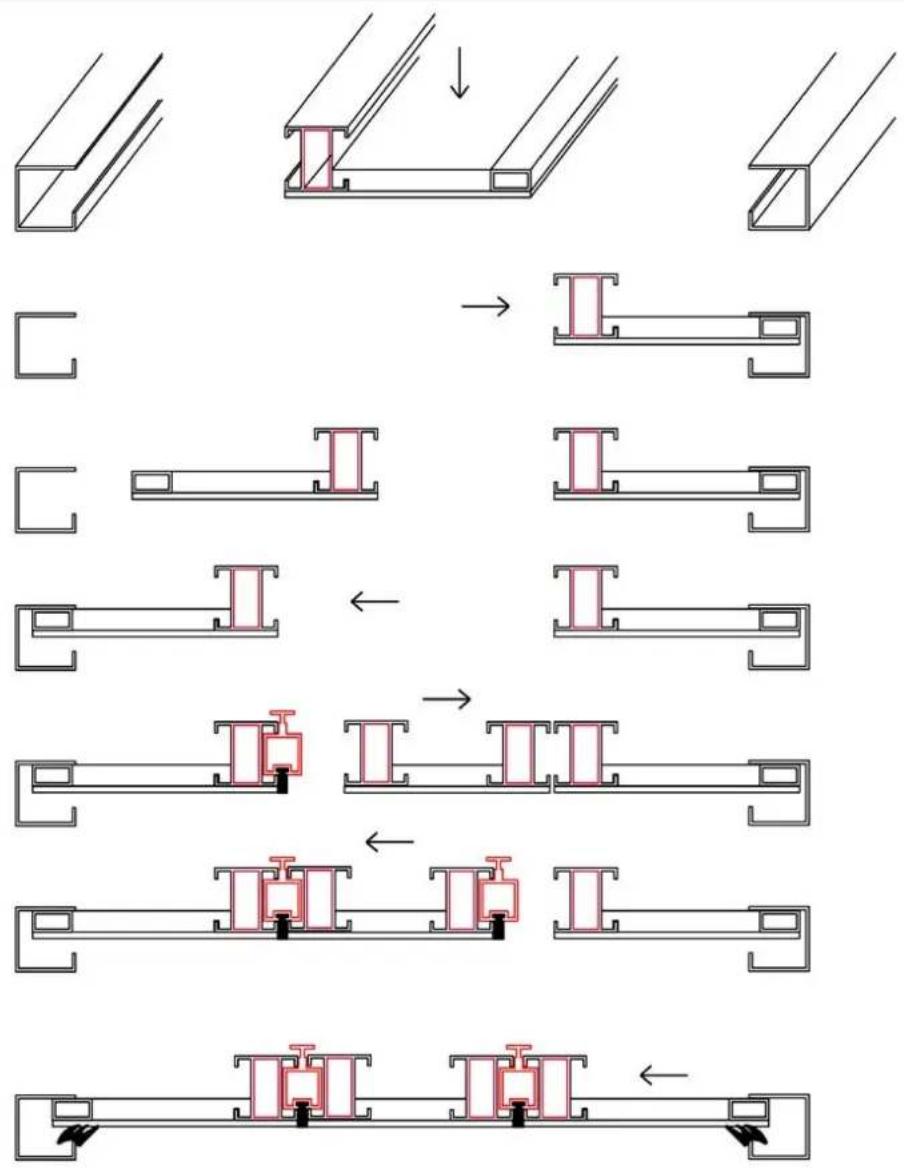
- Once this has been done, find the ceiling modules labelled ceiling 1, ceiling 2, etc. These must be inserted into the profiles and fitted together according to their labelled numbers, following the diagram supplied with the ceiling module.
Following is a diagram to facilitate assembly.

Graphic guide for the installation of prefabricated modules
The number of ceiling modules will depend on the dimensions of the cabin, but the installation system is the same regardless.
- Place the end of the module with the longest fit, into the support profile.

natural_image
Pure curved structural diagram with no text, numbers, or symbols- Fit the other end of the module into the opposite rail on the ceiling support profile.

natural_image
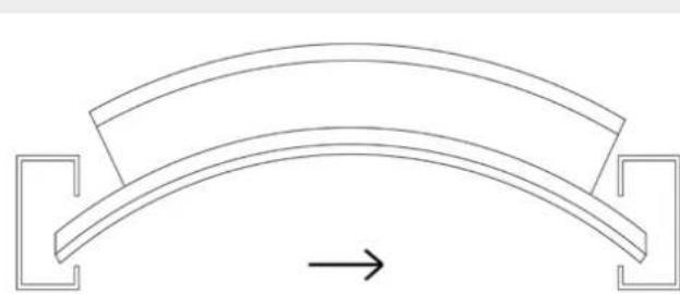
Pure geometric diagram of a curved structural element with corner brackets and an arrow indicating direction (no text or symbols)- Slide the module so that it fits perfectly into the rails. This is done in the middle of the cabin. Once the module is in place it can be moved along the rails into position according to the diagram.
natural_image
Pure geometric diagram of an arched structure with two side brackets and a directional arrow (no text or symbols)- Once all of the modules are fitted, insert the rubber seal as shown.

natural_image
Pure diagram of a curved structural element with directional arrows, no text or symbols presentGraphic guide for the installation of the ceiling modules
flowchart
graph TD
    A["Initial structural component"] --> B{Rebar assembly}
    B --> C["Rebar anchor mechanism"]
    C --> D["Final structural assembly with anchor mechanisms"]
    D --> E["Final structural assembly with anchor mechanisms"]
Due to the continuous condensation of the steam on the surfaces of the cabin, a continuous drip is caused, which is a very disagreeable sensation for users.
For custom built cabins it is considerably difficult to completely prevent dripping, as this not only depends on the pitch and shape of the ceiling, but also on the porosity and unevenness of the materials used for cladding. Fluidra recommends that the ceiling be built using a smooth and non-porous material such as Plexi.
Below are the different shapes for ceilings, according to dimensions of the cabin.
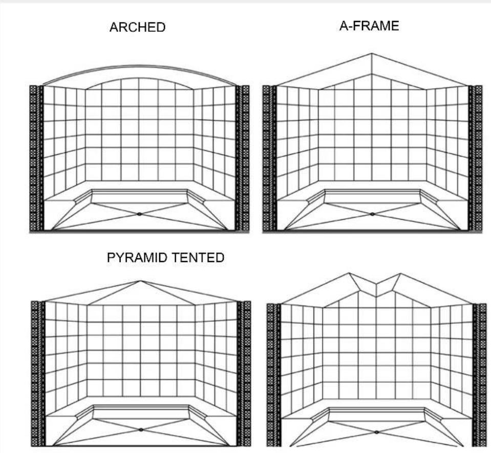
PREFABRICATED CABIN
Advantages of the prefabricated cabin compared to a custom built cabin
1 The cabin does NOT require a SPECIAL LICENCE; a custom built cabin however requires a minor construction work permit as it will affect the layout of the house or premises where it will be installed.
2 Our PREFABRICATED CABIN CAN BE DISMANTLED AND MOVED, which enables its transfer to another place within the same premises or to another place, without affecting the working order of the steam bath in any way. A custom built cabin cannot be moved and therefore the investment made would be lost if the owner were to move premises.
3 Given the construction characteristics of the cabin (module construction type with insulation and an interior acrylic finish), if it is in continuous operation savings of UP TO 50% can be made with regard to CONSUMPTION compared to a custom built steam room.
4 As consumption is lower, the POWER SUPPLY AND INSTALLED VOLTAGE is also lower. It is common to find that an increase in total voltage for the premises is required in the case of custom built cabins.
5 Once the steam bath is started up, the time required for a session to begin is important, above all if it is for professional use. THIS INTERVAL IS MUCH LOWER in a prefabricated steam room compared to a custom built cabin given that the temperature for normal use is reached much faster.
6 The finish on the inside of the cabin (acrylic) is NON-POROUS, therefore PREVENTING TOXINS, MOULD and BACTERIA from penetrating the walls.
The cabin is therefore MORE HYGIENIC than custom built cabins and thanks to its non-porous finish, it can be CLEANED AND DISINFECTED MUCH FASTER AND MORE EFFECTIVELY.
7 The custom built option does not normally have the agreeable sensation of an acrylic finish, therefore users are less likely to use it often. In custom built cabins that are tiled bacteria and mould can accumulate in the joins and corners, which can create bad odours. They are also much more difficult to clean and disinfect.
8 Given that the CABIN is water-tight, LEAKS ARE NOT A PROBLEM, whilst a custom built cabin cannot guarantee this.
9 The condensation produced inside a PREFABRICATED CABIN IS MUCH LESS compared to the custom built cabin, therefore water consumption is considerably lower.
10 OUR COMPANY manufactures steam rooms and supplies them with all the necessary equipment. It also fits out custom built cabins, in cases where very large cabins are required. In these cases the technical-construction requirements for these cabins are supplied and a close monitoring of the construction and materials used is done to optimise the operation of the steam bath.
The following section provides details of the construction system and all of the technical specifications regarding the materials used for constructing a steam room.
Materials and basic components of the steam cabin
First of all, it must be pointed out that although there are similarities between the benefits of a sauna and a steam bath, the materials that should be used for their construction are completely different. A sauna is a dry heat bath and the humidity parameter is the absolute opposite to that of a steam bath, which could be considered a humid heat bath.
The materials used for building a steam bath are listed below and basically include the CABIN, the GENERATOR, the INJECTOR and CONTROL EQUIPMENT.
Materials required for the CABIN:
Wall and ceiling modules:
- 3 mm thick, opaque white acrylic interior face.
- Interior structure with a frame of 10 micron anodised aluminium.
- Layer of polyester resin with a 2 mm thick sheet of fibreglass.
- Module reinforced phenolic plastic laminates.
- Second layer of polyester resin with a 2 mm thick sheet of fibreglass.
- Decorative phenolic sheet on the visible exterior walls.
Lower and upper mounting rims: Exclusive and special mounting rim profile in anodised aluminium, painted white, silver or inox.
Side and corner profiles: Exclusive and special custom-made profiles in aluminium with rounded edges painted white. Self-anchoring system with the modules and mounting rims. Doorframe module in anodised aluminium painted white. Frosted grey, tempered glass door.
Seating:
- Length of benches with structure and finishes made of anodised aluminium painted white.
- Front panel of seating same as the benches. Optional.
The following diagrams provide details and cross-sections of all of the cabin's components.
Horizontal section of the prefabricated cabin

Vertical section of the prefabricated cabin
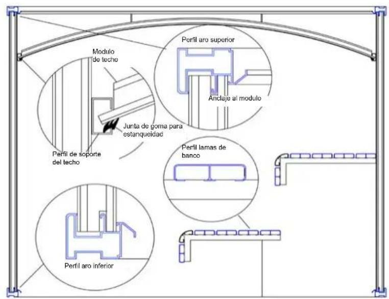
Construction detail and anchoring of the steam bath
The cabin has been designed as a prefabricated room in sections that fit together perfectly, so as to provide a high level of insulation, an ease of steam generation and a leak-tightness that leads to minimum consumption thanks to a rational use of power.
It has been created and constructed so that the sections are easy to assemble and connect to create a perfect installation.
Figure 1 shows a three-dimensional perspective of the prefabricated system of the sections that fit together creating one of the modules.
Detail of components: (Numbered according to assembly order)
N.° 1 LOWER MOUNTING RIM: : Lower perimeter frame in aluminium painted white or as requested for each case, onto which the modules, the side and corner profiles and doorframe are mounted. The floor must be level so that the mounting rim profile sits perfectly.
N.° 2 MODULES: The modules are the sections that enclose the cabin. They are made of aluminium, with an acrylic inner surface and phenolic resin on the outer surface.
N.° 4 MARCO: Module that integrates the cabin door. It is made of 4 sections joined together using stainless steel screws. These are aluminium painted white or the required colour.
N.° 5 PUERTA: Door into the cabin made of 10 mm thick glass. A door handle on each side of the door is attached using stainless steel screws.
N.° 6 ARO SUPERIOR: Upper perimeter frame joined to the corners with brackets. All of the modules that comprise the cabin will be mounted onto this rim. The upper mounting rim is fixed to the modules using 80 mm stainless steel screws.
N.° 7 TECHO: Ceiling anchoring profiles and modules. Final enclosure for the steam cabin.

Available models. Capacity and layout.
In order to meet all of the possible needs of its clients, Fluidra has developed a wide range of standard models. The differences between each of these modules lies mainly in the number of people able to use the steam bath at the same time or in their comfort, as the larger the cabin, the more comfortable it will be for users.
There are 20 different models available and for each one of them details of the shape, dimensions, user capacity, layout and generator characteristics are provided.
The construction system for the cabins has been designed so that any other made-to-measure cabins can be built in addition to the standard models. Cabins with columns, angled corners, models with two doors for mixed steam rooms and even rooms with lofted ceilings can be manufactured. For any of these options, contact your Fluidra dealer.
The steam cabin has been designed and developed for PROFESSIONAL use; therefore its use is INDISCRIMINATE for installations that are private or public.
The construction system is exactly the same for all of the models, regardless of the measurements and capacity. Therefore, small models will be installed for PROFESSIONAL use simply replacing the generator with one that corresponds to the construction and professional features.
The cabins can be adapted to any construction obstacles, with options such as columns, ceilings of a special height, etc.

natural_image
Architectural floor plan and interior layout diagrams showing room layouts and structural elements (no text or labels)The following table provides details of the dimensions and capacity for each one of the cabin models available.
| Mod. Model | Measurements cm | S= Sitting A= Lying down | B= Benches L= Beds | Consumption Kw/h | Generator type |
| INVAP-1 110 | X 110 S=1 A=0 2 B 3 | Domestic | |||
| INVAP-2 130 | X 130 S=2 A=0 2 B 3 | Domestic | |||
| INVAP-3 145 | X 145 S=2 A=0 2 B 4 | Professional | |||
| INVAP-4 160 | X 145 S=3 A=0 2 B 4 | Professional | |||
| INVAP-5 160 | X 160 S=3 A=0 2 B 4 | Professional | |||
| INVAP-6 177 | X 145 S=4 A=0 2 B 4 | Professional | |||
| INVAP-7 177 | X 177 S=4 A=0 2 B 5 | Professional | |||
| INVAP-8 210 | X 145 S=4 A=2 2 B 5 | Professional | |||
| INVAP-9 210 | X 160 S=4 A=0 2 B 4 | Professional | |||
| INVAP-10 210 | X 177 S=5 A=0 2 B 5 | Professional | |||
| INVAP-11 210 | X 195 S=5 A=2 2 B 6 | Professional | |||
| INVAP-12 210 | X 210 S=5 A=0 3 B 5 | Professional | |||
| INVAP-13 245 | X 160 S=6 A=0 3 B 6 | Professional | |||
| INVAP-14 245 | X 195 S=6 A=2 3 B 6 | Professional | |||
| INVAP-15 245 | X 210 S=6 A=0 3 B 6 | Professional | |||
| INVAP-16 245 | X 245 S=7 A=2 4 B 6 | Professional | |||
| INVAP-17 275 | X 177 S=9 A=4 4 B 9 | Professional | |||
| INVAP-18 275 | X 210 S=10 A=5 5 B 9 | Professional | |||
| INVAP-19 275 | X 245 S=10 A=4 4 B 9 | Professional | |||
| INVAP-20 | 275 X 275 | S=14 A=5 | 5 B | 12 | Professional |
* Larger and special sized cabins can be made to order.
* The exterior height of all of the models is 220 cm.
* All of the models include the visible decorative façade panelling.
* OPTIONAL: All models can have a mixer tap and shower hose incorporated.
* OPTIONAL: All of the models with domestic generators can include professional equipment.
* OPTIONAL: All models can have the following installed: CHROMOTHERAPY, MULTIPLE AROMATHERAPY, FIBER OPTIC LIGHTING, STARRY SKY LIGHTING, etc...
Assembly and installation process
IMPORTANT: Before beginning to assemble the cabin, remember that this cabin has been factory assembled and that all of the parts have been fitted and adjusted. All of the electric and hydraulic components have been tested. Therefore, do not force any of the components. Carefully read the guide and correct the error.
Assembly of the cabin
The steam bath has been especially designed and built for ease of assembly by everyone, regardless of their knowledge on plumbing and electricity. The complete kit is supplied, including all of the parts and accessories necessary for installation. For each unit complete instructions are provided that will solve any problems that may arise. All of the parts are labelled, corresponding to each stage of assembly and detailed illustrations and descriptions are provided. Therefore, installing the cabin is an easy and simple task for any layman. The cabin assembly involves completing 5 key stages:
1 Positioning and anchoring the lower mounting rim profile using its fittings in the place and orientation that the cabin should be once completed.
2 Fitting the modules, together with their side and corner profiles onto the base mounting rim in the order and way shown.
3 Once the perimeter walls have been put in place, fitting the four sections of the upper mounting rim (aluminium profile) onto the modules according to their labels. Anchoring the mounting rim parts to each other and to the modules.
4 Fitting the ceiling onto the support profile previously put in place.
5 Installing the interior fittings: benches, front panels, steam heads, etc. as shown and connecting the electrical equipment (developed specifically).
All of the anchoring fittings that are supplied must be used in the correct place and position to ensure the correct installation and leak-tightness of the cabin.
On the following pages, the order of assembly and installation is shown and described, step by step, so that as long as each one is completed correctly, the steam bath will work perfectly.
Procedure for installing the steam cabin

natural_image
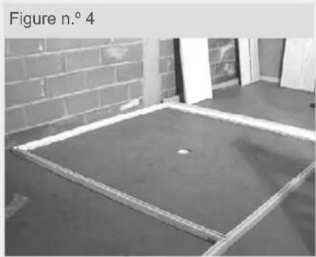
Close-up of a drill bit on a metal bracket, no visible text or symbolsOnce taken out of its packaging, select the parts that will make up the base mounting rim.

Position them according to their labels: FAÇADE, RIGHT, BACK and LEFT. Anchor the parts together using the pre-fitted brackets at the ends.
natural_image
Exterior view of a concrete floor with a rectangular metal frame and brick wall background (no signage or text)Remember that the way the base rim is positioned will determine the position of the cabin once it has been assembled.
Make sure it is in the correct position before continuing. Once assembled this cannot be altered.
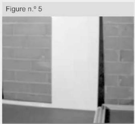
natural_image
Exterior view of a brick wall with a vertical window and partial corner detail (no signage or text)Select the modules for one of the comers according to the numbering on the plans for this cabin and anchor them to the corresponding corner of the base mounting rim.

natural_image
Person using a handheld tool on a vehicle door, no visible text or symbolsThe junction profile and side and corner profiles must be sealed with silicone as shown in the figure. Repeat this step for the four walls.

natural_image
Exterior view of a modern office building (no signage)
natural_image
Exterior view of a white door with a brick wall and window frame (no signage or text)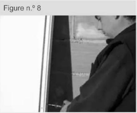
natural_image
Black-and-white photo of a person standing near a window, no visible text or symbolsThe panels must be anchored to the side and corner profiles using 70 mm screws as shown in the figure.

natural_image
Person standing beside a large white panel or cabinet, possibly a refrigerator or storage unit (no visible text or symbols)Repeat this for each of the four walls.

natural_image
Exterior view of a white cabinet with a shadow on the side (no visible text or symbols)The panels will slot together without the need for any screws or fittings. Once the upper mounting rim is in place they will be fixed into place and leak-tight preventing any movement.

natural_image
Interior corner of a room with white walls and a door, labeled Figure n.° 11 (no other text or symbols)Screws will only be used to fit the abutting panels to the corner profiles. For the visible sides of panels covers will be provided for the screw heads. The screws used to join the corner profiles to the modules are stainless steel and of high resistance.
natural_image
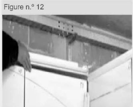
Person installing or adjusting a white cabinet panel inside a ceiling structure (no visible text or symbols)For this step, select the four parts that will form the upper mounting rim of the cabin. These must be fitted onto the modules according to the labels, in the same way as the base mounting rim.

These parts will be connected using the pre-fitted brackets on each using 16 mm screws. Each bracket must have 6 screws.

natural_image
Person using a drill bit on a metal frame, no visible text or symbolsSimilar to the base the four parts are labelled: FAÇADE, RIGHT, BACK and LEFT. Once the upper mounting rim is in place, the modules must be anchored to it.

natural_image
Person holding a camera on a wooden cabinet (no visible text or symbols)This is done using 60 mm screws placed vertically in the holes along the perimeter of the rim.
natural_image
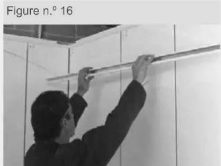
Person measuring a wall-mounted object in a cabinet (no visible text or symbols)Once the upper mounting rim has been fitted, the support profiles for the ceiling modules must be installed. These profiles are labelled the same as the upper and lower rims: RIGHT, LEFT, BACK and FAÇADE.
Figure n.° 17

natural_image
Close-up of a hand using a tool to apply white adhesive on a metal surface (no visible text or symbols)Before anchoring them the silicone sealant supplied with the cabin must be applied, as shown in the figure. This will ensure maximum leak-tightness of the ceiling.
Figure n.° 18

natural_image
Person installing or adjusting a wall-mounted component in a clean room (no visible text or symbols)First of all the straight profiles must be put place according to their corresponding position; the curved profiles will be fitted after. These will be fixed in place using 16 mm screws.
Figure n.° 19

natural_image
Person holding a small object against a wall, no visible text or symbolsin Once all the profiles have been fixed in place, seal the joins with silicone, as shown in figure 19.
Figure n.° 20

natural_image
Close-up of a ceiling structure with arched and rectangular elements, no visible text or symbolsOnce this has been done, select the ceiling modules labelled CEILING 1, CEILING 2, etc.
Figure n.° 21

natural_image
Architectural structure with curved architectural elements and grid patterns (no visible text or symbols)These must be fitted into the profiles and each other according to their labelled numbers, following the diagram supplied with the installation guide.
Figure n.° 22

natural_image
Exterior view of a modern office building (no signage)This assembly process, although simple can appear to be somewhat complex the first time.
natural_image
Person reaching toward a curved ceiling structure (no visible text or symbols)For this reason, apart from the figures that may be difficult to interpret, diagrams of the installation process are also provided.

natural_image
Pure architectural line drawing of a 3D building facade with vertical supports (no text or symbols)Once the ceiling modules are in place in the profiles, the rubber seal is fitted to fix them in place and ensure leak-tightness.
Figure n.° 25

natural_image
Close-up of hands holding a black cable with wires, no visible text or symbolsIf fitting the rubber seal is difficult, use a cutter to gently press the seal into place.
If this does not help, use a screwdriver to lever the ceiling panel so that the gap is larger.
Figure n.° 26

natural_image
Man installing or adjusting ceiling panels in a room (no visible text or symbols)In the corners the rubber seal must be cut to create a mitre joint and ensure leak-tightness and a better finish.
Figure n.° 27
natural_image
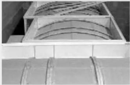
Close-up of a wooden structure with curved internal panels and layered base (no visible text or symbols)External view of a completed ceiling.
Figure n.° 28
natural_image
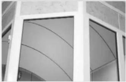
Exterior view of a modern building corner with arched glass panels (no signage or text visible)Internal view of a completed ceiling.
Figure n.° 29

natural_image
Close-up of a hand holding a tool near a white panel, with no visible text or symbols.As shown in the figure, the next step is to install the seating.
Figure n.° 30

natural_image
Person using a glue gun to lift a wall-mounted tool (no visible text or symbols)Before fitting the bench supports, seal around the holes in the wall with silicone. Following this, fix the support using 30 mm screws. This will prevent noise when sitting down or getting up from the seat.
Figure n.° 31

natural_image
Person installing or repairing a wall-mounted panel (no visible text or symbols)Place the seating supports in the corresponding position according to the numbering as shown in the figure. Once all of the supports have been installed, the benches can be put in place. LEVEL 1, LEVEL 2, LEVEL 2 right, etc. This numbering must coincide according to the specific plan for the cabin, provided with this guide.
natural_image
Person standing beside a white staircase with shelves, no visible text or symbolsPlace the bench on the support, right or left followed by the other end

natural_image
Close-up of a hand using a power tool to press or install a white sheet of paper into a machine (no visible text or symbols)Fix in place using screws.

Temperature selector

Aroma oil

Decr.

OK / Enter

Timer

Ventilador
General operation
This equipment has the following functions:
• Control of water level in the boiler tank
• Regulation of steam bath temperature
- Heating control
- Ventilation control
- Lighting control
- On/off timer
- Aroma oil control
- Fault detection
Selection keys

Aroma oil
The aromatherapy system is automatically activated when the control panel is switched on. This can be switched on / off at any time using this key. Press the key for a few seconds to access the set-up menu. Using the + and - keys the time that the aroma oil is diffused (seconds) followed by the pause between diffusions (minutes) can be controlled. To accept changes press ENTER.

Optional menus
Pressing this key the menu for activating optional elements of the steam bath will open. To select the option use the + and - keys and press ENTER to open the specific menu.
- Chromotherapy: This optional element has 3 items that can be selected using the + and - keys.
- Programme: Select one of the three programmes.
- Lightbulb: Switch chromotherapy on or off.
- Fiber optic chromotherapy (FO): This optional element has 2 items that can be selected using the + and - keys.
- On/Off: Switch the FO chromotherapy on or off. To switch if off press ENTER for 4 seconds.
- Colour: Selection of a specific colour. By default when switching on the chromotherapy system, the colours will alternate automatically but if a single colour is desired this can be activated in this window.

Lights
The cabin lighting is switched on and off automatically with the steam bath. This can be controlled at any time by pressing this key.

Timer
This can be accessed by pressing this clock, regardless as to whether the steam bath is on or off. When pressed the time shown after which the system will switch off is displayed, with a minimum of 30 minutes. This can be altered by 15 minute intervals using the + and - keys. To accept changes press the key again, it will remain lit up, indicating that the system has been programmed. If a switch off is programmed whilst the system is off, this will begin as soon as the steam bath is switched on. If the system is on, it will begin immediately, showing the remaining time on the screen. Once the switch off time has been programmed this will be repeated each time the steam bath is switched on, until it is deprogrammed.

Temperature selector
This is the desired temperature in the cabin and is shown on the right of the screen. To change the temperature press this button and use the + and - keys. To accept the chosen temperature, press the key again. If nothing is pressed changes will not be saved and after 10 seconds the screen will return to normal.

Fan
The ventilation system is activated automatically when the steam bath is switched on and shuts down 20 minutes after it has switched off in order to eliminate accumulated steam from the cabin. This option should not be altered
Inlet / outlet screen:
This screen shows the status of each of the outlets and inlets. It can be accessed by pressing the menu and clock keys simultaneously for a few seconds. To escape, press the °C key. Below is an explanation of the meaning of the fields that are shown on the screen:

Level sensor status screen:
To control the level of water, the boiler has a sensor with two redundant levels at the same height. If one of them stops working properly the system detects the problem and works with the other one only. This screen can be accessed from the previous screen by once again pressing the menu and clock keys for a few seconds simultaneously. This screen shows the status of the level sensor. For example, if For example: NIV 1: OK – NIV 2: X is shown, this means that level 1 is working correctly and level 2 is not being used. The system is designed to work with either level. If both stop working the sensor will need to be replaced. Once the sensor has been replaced, the equipment must be told, by accessing the screen and resetting it by pressing the Light key. Once it is reset the following should appear on the screen "NIV 1: OK – NIV 2: OK".
Troubleshooting
---Temp.prob.s-circ. Contact Tech. Serv. The temperature probe has short circuited
----Faulty temp prob. Contact Tech. Serv. The temperature probe is detecting a value much higher than the selected temperature and is therefore most likely faulty.
----Waste blocked. Contact Tech. Serv. The system has been trying to empty the boiler tank for too long. Blocked drain, solenoid draining valve or level sensor are faulty.
----Failure Num. Contact Tech. Serv. Contact customer service.
----Temp. alarm. Contact Tech. Serv. The safety thermostat has gone off due to high temperature. This must be corrected before restarting the equipment.
----Boiler not fill. Contact Tech. Serv. The system has been filling with water for too long and there is no change in the levels: there is no water supply, filling valve is faulty, draining valve is open or the level sensor is faulty.
----No data received. Contact Tech. Serv. The connection between the keypad and the generator is faulty. A wire is broken or disconnected.
----Ventilator off: system stopped If the ventilation is switched off manually with the steam bath on and this continues for more than quarter of an hour, this message will appear. Simply restart the ventilation to return the system to normal.
----Vent. inverted. Contact Tech. Serv. The condensation ventilator that has a direct current is connected back to front, the polarity must be inverted.
----Water not evap. Contact Tech. Serv. The system has detected that, after 20 minutes, there has been no change in the levels. Level sensor faulty. Cabin temperature much higher than selected temperature.
Troubleshooting guide
Replacing the level controller
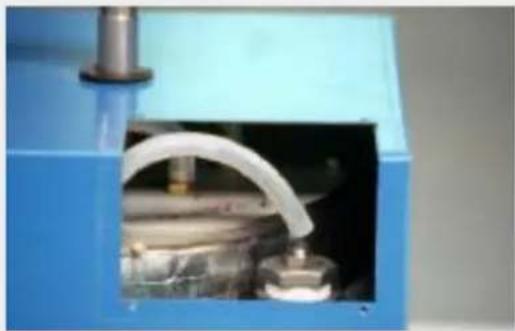
- Remove the cover where the level controller is located, as shown in Figure 1.
- Using a suitable wrench, unscrew the lid where the level controller is positioned, as shown in Figure 2.
- Cut the connecting wire to the controller as close as possible to it.
- Undo the screw that fixes the controller to the lid and remove it.
- Fit the new controller with the copper gasket in the same position as the previous one.
- Wrap the threads with Teflon tape and screw on correctly. WARNING: it is essential that it should be screwed on to make a perfectly tight fit, otherwise errors may occur in the levels.
- Use a connector to reconnect the wire, ensuring the colours correspond correctly.
natural_image
Close-up of a blue industrial machine with a white curved pipe opening, showing internal components (no visible text or symbols)Figure 1

natural_image
Close-up of a hand operating a pressure regulator device with tubing, next to a blue industrial container (no visible text or symbols)Figure 2
Resetting the safety thermostat
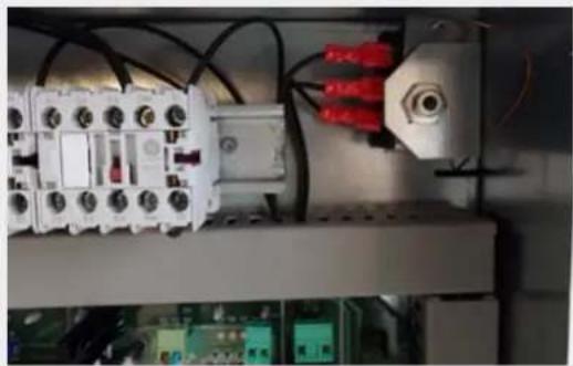
When the steam generator overheats, due to excess mineral salts inside the boiler tank, or the steam pipes, the thermostat will automatically trigger. This is located inside the generator shown in the figures below.
natural_image
Electrical control panel with white components and red connectors, mounted on a circuit board (no visible text or symbols)Figure 3

Figure 4
To reset the thermostat:
- Remove the front cover of the generator.
- Unscrew the black cover shown in Figure 3.
- Press the button until the thermostat is reset.
Replacing the safety thermostat
To replace the safety thermostat, follow the steps below:
- Remove the front cover of the generator.
- Disconnect the steam outlet pipe, unscrew the tee and disconnect it from the generator.
- Remove the cover from the generator.
- Unscrew the black cover and disconnect the electric cables, remembering the position of the connections.
- Unscrew the thermostat locknut.
- Pull the copper pipe up to remove the thermostat sensor.
- Very carefully install the new thermostat, the copper pipe is very fragile.

natural_image
Close-up of electrical equipment with wires and components, no visible text or symbolsFigura 6
Replacing the electrical resistors
- Remove the generator covers as described in the previous figures.
- Mark and disconnect the electrical resistor wires, as shown in Figure 7.
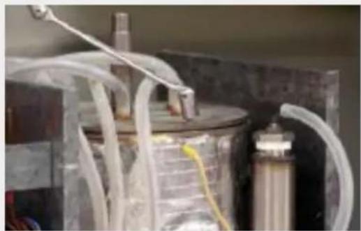
- Remove the screws from the top cover using a hex key, as show in Figure 8.

natural_image
Close-up of a mechanical device with transparent tubing and a central cylindrical component (no visible text or symbols)Figura 7
natural_image
Close-up of a laboratory apparatus with white tubing and a metallic container (no visible text or symbols)Figura 8
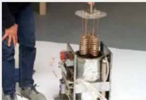
- Remove the cover from the generator as shown in Figure 9.
- Replace the faulty resistors by loosening the top screws. Place the copper gaskets supplied in the same place as they were located. To ensure leak-tightness, seal the joins.
- Make the most of this procedure to clean the boiler completely using a descaling agent
natural_image
Close-up of a mechanical device with copper coils and a person standing nearby (no visible text or symbols)Figure 9

natural_image
Person operating a mechanical device with coiled spring, no visible text or symbolsFigure 10
Cleaning the draining valve
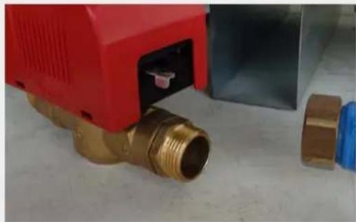
For installations where there is an excess of limescale in the water, it is common for the draining valve to become blocked. To clean the valve, follow the instructions below. Loosen the nuts that fasten the valve and remove the pipe and the valve. Clean the copper pipe, the valve and the bottom of the generator pipe using a wire or something similar. To ensure that they are clean, a descaling agent can be used on all of the parts. Do this using a brush.

natural_image
Interior view of a room with blue and red pipes and a red valve, no visible text or symbolsFigure 11
natural_image
Close-up of a red industrial valve component with brass fittings, next to a blue and metallic housing (no visible text or symbols)Figure 12
Cleaning the filling valve
For installations where there is an excess of limescale in the water, it is common for the draining valve to become blocked. To clean it, remove the valve and clean the filter as shown in Figure 14.

natural_image
Close-up of a mechanical or electrical component with metallic wiring and a copper pipe, no visible text or symbolsFigura 13

natural_image
White humanoid robot on a blue workbench, no visible text or symbolsFigura 14
Replacing the safety fuse
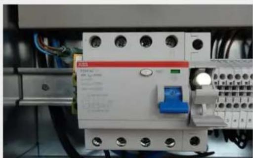
The generator is protected by a safety fuse, to protect the machinery from any electrical anomaly. If there is power but the generator is not working, replace the fuse with one that has the same characteristics (B-type fuse link)

natural_image
Electrical circuit breaker with ABS panel and wiring, no visible text or symbols on componentsFigure 15
natural_image
Close-up of an electrical circuit breaker with a blue switch and red panel, mounted on a grid base (no visible text or symbols)Figure 16
Maintenance guide
- Press the circuit breaker test button to check that it is working properly.
- Make sure there are no water or steam leaks in the safety valve on the steam pipe outlet.
- Test the water supply to ensure that it meets the correct parameters with regard to water hardness.
- Ensure that the water softener, if installed, is full of salt and that this is being used. If the softener is not using the salt it is not working properly.
Sometimes the water supply has other residues. According to the region, other residues may be found in the water that are not absorbed by the softener. It is also possible that the water softener is not working properly or that there has been a change in the water supply. If this were the case, residue will accumulate in the generator until the processor detects that it is not working correctly due to obstruction of the pipes. The generator's boiler tank must be cleaned to solve this problem.
Cleaning the boiler This must only be done by our Technical Service or by a technician qualified and authorised by Fluidra. To clean the boiler, follow the instructions below:
- Completely disconnect the power supply.
- Remove the front cover of the generator.
- Disconnect the steam outlet pipe, unscrew the tee and disconnect it from the generator.
- Remove the cover from the generator.
- Remove the safety thermostat sensor.

natural_image
Close-up of industrial equipment with coiled copper pipes and wiring, no visible text or symbolsFigure 1

natural_image
Laboratory setup with coiled tubing and a metallic cylindrical container (no visible text or symbols)Figure 2

natural_image
Close-up of a mechanical device with transparent tubing and a metallic housing (no visible text or symbols)Figure 3
natural_image
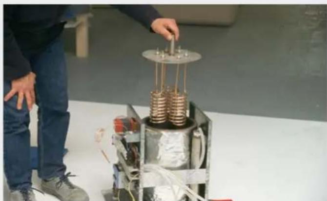
Person standing beside a metallic mechanical device with copper coils and wires, no visible text or symbolsFigure 4
- Unscrew the nuts using a hex key.
- Disconnect the electrical resistor wires. Mark the cables to prevent connection errors.
- Remove the cover with the resistors.
- Unscrew the level controller. (The electric wire should be cut first).
- Remove the draining valve.

natural_image
Close-up of a laboratory apparatus with a hand holding a transparent tube connected to a metallic component (no visible text or symbols)Figure 5

natural_image
Close-up of a red and blue industrial control device with brass fittings and copper pipe (no visible text or symbols)Figure 6

natural_image
Close-up of a metallic cylindrical mechanical component with a central circular opening, attached to a flanged metal bracket (no visible text or symbols)Figure 7

natural_image
Metallic mechanical component with wiring and red connectors, no visible text or symbolsFigure 8

natural_image
Close-up of a mechanical assembly with red arrows pointing to components, no visible text or symbolsFigure 9

natural_image
Close-up of a metallic cylindrical container with a central hole and two red arrows pointing to the interior (no text or symbols visible)Figure 10
- Once all of the components have been dismantled, remove the solid residue at the bottom of the boiler tank.
WARNING: ENSURE THAT THE CORRECT PROTECTION CLOTHING (GLOVES AND MASK) IS USED. DO NOT INHALE THE DESCALING AGENT GAS. COMPLETE THIS OPERATION IN A WELL-VENTILATED PLACE.
- With the help of a descaling agent and a paint brush, clean all the metal parts of the boiler and all of the accessories, as well as inside the connection pipe, elbows and dowels where they join, the copper drain pipe, draining valve, level controller, etc...
- Once all of the generator components are clean, reassemble the machine. Take care to replace all of the component seals to ensure maximum leak-tightness of the machinery.
- Make sure that all of the wires are correctly connected and secured. Remember that when connecting the power supply always start with the ground connection.
- The expansion pipe with its two dowels and the connection pipe are very important. (Figures 9 and 10)
IMPORTANT: The equipment is not designed for use by people (including children) with reduced physical, sensorial or mental abilities, or by those who do not have adequate knowledge or experience, unless they are suitably supervised or have received the necessary instructions for using the equipment from a person responsible for their safety. Children must be supervised to ensure that they do not play with the equipment.
STEAM BATH RULES FOR USE
Ideally users should wear a swimming costume or nothing when using the steam bath. Towels and other elements that could be damaged by water, such as non-waterproof watches or radios, etc. should not be taken inside the cabin.
Normally in a cabin of this type, no other complementary activities are carried out, such as reading, as these elements will be damaged by the level of humidity.
A steam bath should be used the same way as a sauna, although the session times may be longer, as a steam bath is gentler as are its effects.
How to take a steam bath:
1 Shower prior to entering the cabin.
2 Remain in the cabin, enjoying the steam bath for an initial session of between 10 and 20 minutes, although this will depend on each person and on his or her health. Do not remain inside the cabin for too long, steam bath times are relative to each person at different times. If you feel the need to cool down, leave the cabin.
3 Take a shower after with the water at room temperature.
4 Return to the cabin and repeat step 2.
5 Steps 1 to 3 can be repeated up to 3 times, but users must never force themselves to continue.
6 The time between sessions can be combined with fresh air, relaxation and placing feet in warm water.
7 Cooling down sessions of 15 to 20 minutes should be done afterwards, if possible lying down. It is likely that you will continue to sweat during the cool down period until skin pores have closed.
8 Shower once more to conclude the steam bath session.
Contraindications
Although there are very few cases in which steam baths are not recommended, below are the most important. First of all, as with all activities that directly affect the body, consult your doctor before using the steam bath.
1 Do not take a steam bath after eating.
2 Do not take a steam bath if you are pregnant.
3 Do not take a steam bath during menstruation.
4 People with serious heart conditions must not use the steam bath.
5 Steam baths are not recommended for people with hypotension.
6 People with advanced cases of arteriosclerosis and tuberculosis must not use the steam bath.
Specific considerations
Do not enter the steam bath after exercising until you have completely recovered.
- Do not drink alcohol either before or after the session.
- Do not remain in the steam bath if you feel the need to cool down as this will affect the positive effects of the session. Similarly it is better not to leave the steam bath until you feel this need, so as to maximise the results of the therapy.
- Each person will feel this need to cool down after a different period of time. What's more, each person, at different times will be able to spend more or less time in the steam bath, according to how their nervous system or metabolism is at each given time. For this reason, it is better not to set a specific amount of time for remaining in the steam bath.
CLEANING AND DISINFECTING THE AROMA OIL SYSTEM
As previously mentioned, each module is supplied with a disinfecting product with a sprayer. This product is supplied in bottles of one litre and is a fungicide and bactericide that kills off germs that cause bad smells. This product ensures that steam bath users find the cabin in perfect condition for use, preventing bad smells, mould and/or bacteria in the cabin.
Cleaning product: A product suitable for eliminating dirt from the cabin walls, ceilings, floors and benches. It is odourless and contains a disinfectant.
Application: It is applied using a sponge or cloth soaked with the product. Gloves should be used. Private cabins should be cleaned once a week or once a month. Public cabins should be cleaned daily or once a week. This depends on the level of use of the cabin.
Disinfecting product: Use after cleaning, once the cabin has cooled down. This is a broad-spectrum fungicide and bactericide. It destroys the germs that cause bad smells.
Application: Apply by spraying on the floor and benches inside the cabin.
For public use cabins the disinfectant should be used daily, before the steam bath is switched on, regardless as to whether it was cleaned the day before or not. The product can also be applied at the end of the day, once the cabin has cooled down.
DO NOT INGEST. KEEP OUT OF REACH OF CHILDREN. NEVER LEAVE THE BOTTLE OPEN.
The information included in this guide is correct according to Inbeca's criteria. However, as the conditions in which these products are used is out of Inbeca's control, it will not be held responsible for the consequences of their use.
REQUIRED POWER OF THE GENERATOR WITH REGARD TO CABIN SIZE
| Metros cúbicos Potencia equipo Número de generadores Número de tubos | ||
| From 0 to 2.5 4 kw 1 | ||
| From 2 to 6 6 kw 1 1 | ||
| From 6 to 12 9 kw 1 1 | ||
| From 12 to 17 12 kw 1 | 1 | |
| From 17 to 33 18 kw 2 | 2 | |
| From 33 to 42 21 kw 2 | 2 | |
| From 42 to 52 24 kw 2 | 2 | |
SECTIONS AND PROTECTIONS FOR ELECTRIC CABLES
| Metros cúbicos Potencia equipo Número de generadores Número de tubos | |||
| 4 Kw 220-I+N 4 m/m 20 A | |||
| 4 Kw 220-III 2.5 m/m 15 A | |||
| 6 Kw 220-I+N 10 m/m 30 A | |||
| 6 Kw 220-III 4 m/m 15 A | |||
| 6 Kw 380-III+N 2.5 m/m 10 A | |||
| 9 Kw 220-III 6 m/m 25 A | |||
| 9 Kw 380-III+N 4 m/m 15 A | |||
| 12 Kw 220-III | 10 m/m 35 A | ||
| 12 Kw | 380-III+N 6 m/m 20 A | ||
| 18 Kw 220-III | 16 m/m 30 A | ||
| 18 Kw | 380-III+N | 10 m/m 50 A | |
| 21 Kw 220-III | 25 m/m 60 A | ||
| 21 Kw | 380-III+N | 16 m/m 35 A | |
| 24 Kw 220-III | 25 m/m 65 A | ||
| 24 Kw | 380-III+N | 16 m/m 40 A | |
ECOTOUCH ELECTRICAL DIAGRAM


- CONTENTS
- Custom built cabin
- Prefabricated cabin
- Control panel
- Steam bath rules for use
- STEAM BATH INSTALLATION GUIDE
- Location of the generator:
- Incorrect installation:
- Incorrect installation: Correct installation:
- CONSTRUCTION OF THE CABIN AND PRE-CONSTRUCTION INSTALLATIONS
- Construction system for the steam bath
- Advantages of the prefabricated ceiling
- Installation of the prefabricated ceiling
- Graphic guide for the installation of prefabricated modules
- Graphic guide for the installation of the ceiling modules
- Advantages of the prefabricated cabin compared to a custom built cabin
- Materials and basic components of the steam cabin
- Wall and ceiling modules:
- Seating:
- Horizontal section of the prefabricated cabin
- Vertical section of the prefabricated cabin
- Construction detail and anchoring of the steam bath
- Available models. Capacity and layout.
- Assembly and installation process
- Assembly of the cabin
- Procedure for installing the steam cabin
- General operation
- Optional menus
- Lights
- Timer
- Temperature selector
- Fan
- Inlet / outlet screen:
- Level sensor status screen:
- Troubleshooting
- Troubleshooting guide
- Replacing the level controller
- Resetting the safety thermostat
- Replacing the safety thermostat
- Replacing the electrical resistors
- Cleaning the draining valve
- Cleaning the filling valve
- Replacing the safety fuse
- Maintenance guide
- How to take a steam bath:
- Contraindications
- Specific considerations
- CLEANING AND DISINFECTING THE AROMA OIL SYSTEM
- REQUIRED POWER OF THE GENERATOR WITH REGARD TO CABIN SIZE
Brand : ASTRALPOOL
Model : Cala
Category : Temperature Controller