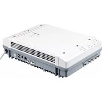
UFO 83 - Digital TV Receiver KATHREIN - Free user manual and instructions
Find the device manual for free UFO 83 KATHREIN in PDF.


| Product Type | Satellite Dish Antenna |
| Model | UFO 83 |
| Brand | Kathrein |
| Reflector Diameter | 83 cm |
| Material | Aluminum |
| Color | Silver/Grey |
| Weight | Approx. 5 kg |
| Mount Type | Wall or pole mount |
| Frequency Range | 10.7 - 12.75 GHz (Ku-band) |
| Gain | Approx. 33 dBi |
| Polarization | Linear (H/V) |
| Connector Type | F-type |
| Operating Temperature | -30°C to +60°C |
| Wind Load | Up to 120 km/h |
| Protection Class | IP54 |
| Included Components | Reflector, feed horn, LNB bracket, mounting hardware |
| Maintenance | Clean with soft cloth; avoid abrasive cleaners |
| Safety | Installation by qualified personnel recommended |
| Spare Parts | LNB, mounting brackets available from Kathrein |
| Repairability | Modular design; feed and LNB replaceable |
Frequently Asked Questions - UFO 83 KATHREIN
User questions about UFO 83 KATHREIN
0 question about this device. Answer the ones you know or ask your own.
Ask a new question about this device
Download the instructions for your Digital TV Receiver in PDF format for free! Find your manual UFO 83 - KATHREIN and take your electronic device back in hand. On this page are published all the documents necessary for the use of your device. UFO 83 by KATHREIN.
USER MANUAL UFO 83 KATHREIN
This document is part of the product.
▶ Install and use the unit only after you have read and understood this document.
▶ Keep this document for reference throughout the life of the device. Pass this document on to the next owner and user of the device.
For the current version of this manual, go to the Kathrein website www.kathrein-ds.com.
Features
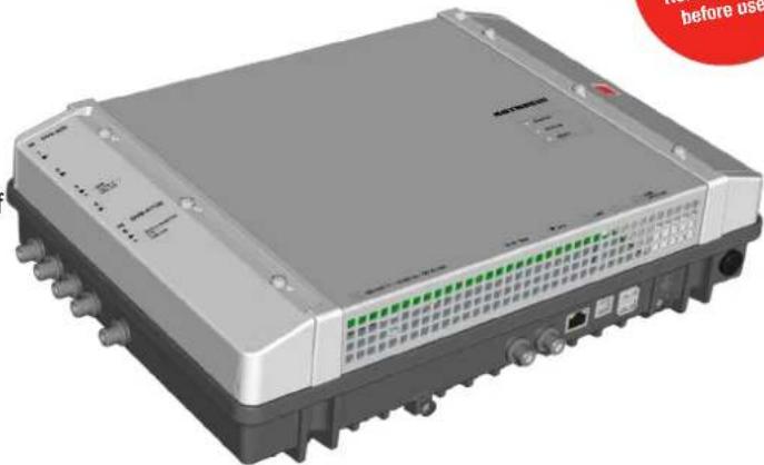
■ Stand-alone head-end with 8-way multi-standard frontend DVB-S(2)/-T(2)/-C and 8 output channels conforming to DVB-T (flexibly configurable)
■ Outstanding output values due to direct implementation as FPGA solution
■ High level of energy efficiency
■ 4 Sat-IF inputs with DiSEqC1.0 functionality for sat multi-switches and 1 terr./cable input, flexibly distributable across 8 multi-standard frontends
■ Power supply for LNB and active antennas
■ All transmission parameters can be set using the USW 800 configuration software
natural_image
3D rendering of a gray network switch device with ports and ventilation grilles (no visible text or symbols)■ Remote maintenance and configuration
■ Comprehensive baseband signal processing with channel filter functionality such as NIT, LCN
■ Cascade capability for two head-ends (16-way multi-standard frontend and 16 x DVB-T) for common configuration and NIT generation incl. LCN
■ No fan, therefore no noise and no maintenance
Scope of supply
- UFO 83
• Wall mounting plate - User instructions
• Third Party Software Acknowledgement
Function blocks

flowchart
graph TD
    A["Input Frontend Baseband Output"] --> B["4 x Sat-IF/1 x terr./cable DiSEqCTM"]
    A --> C["Matrix 5 to 8"]
    A --> D["Power supply LNB and current antennas"]
    A --> E["Special features"]
    E --> F["Energy-efficient"]
    E --> G["Thermal cut-out"]
    E --> H["3 Watt/COFDM (typical) 1"]

    A --> I["8 x DVB-S2/-T2/-C"]

    A --> J["Channel filter"]
    A --> K["NIT generation"]
    A --> L["CAT matching"]
    A --> M["Extended LCN processing"]

    A --> N["8 x DVB-T"]
1) typical for the following input: 4 x DVB-S, 2 x DVB-S2, 2 x DVB-T2, no LNB/antenna supply
Intended Use
The UFO 83 is used for transmodulation of DVB signals. The latest triple-tuner technology makes it possible to receive up to eight DVB-S(2)/-T(2)/-C transponders. These can be received from the four Sat-IF inputs with DiSEqC™ functionality and the terrestrial/cable input in any combination. The UFO 83 delivers up to eight individually configurable output channels conforming to DVB-T.
The highly efficient baseband signal processing offers channel filter, NIT, CAT and LCN functionality. The configuration is carried out by means of the USW 800 management software over an IP interface. An optional cascading of two units (UFO 83 or/and UFO 83/CI) is possible via a USB connection.
The unit is intended exclusively for the application in the UFG 810 as well as in satellite, cable or antenna reception systems. Any other use of failure to comply with these instructions will result in voiding of the guarantee or warranty.
General safety instructions
- The device can be connected to the power supply and disconnected from it only by means of the power plug. Make sure that the connected power plug is always freely accessible and easy to reach.
- If the casing is damaged, do not connect the device to the power supply.
- If the device and/or the cables connected to it are damaged, immediately disconnect the system from the power supply. Do not switch the system on again until
–the device has been repaired by the dealer or manufacturer,
—and the cables connected have been repaired by a competent person. - Do not open the casing and do not modify the device. Otherwise the guarantee and warranty will become void.
- Never cover the cooling ribs or the air circulation openings.
- Do not modify, remove or disfigure the notices and markings applied by the manufacturer.
- Refer to the manufacturer's documentation before connecting external components other than those described in this document (such as computers, network components). Incorrectly connected components can damage the device.
- Refer to the current issue of the safety requirements EN 60728-11 and EN 60065.
- Disconnect the device from the power supply before performing mechanical work on the system.

WARNING
Risk of burns from hot surfaces!
In the event of a defect the heat sink of the unit may exceed 70irc C.
▶ Do not touch the heat sink when the device is in operation or has recently been in operation.
Note
In the event of overheating, the device will shut down automatically and after it has cooled down will switch on again automatically.
Transportation and Storage
▶ Transport and storage the unit in its original packaging.
▶ Protect the unit against dust, dirt, moisture and direct sunlight.
▶ Transport and store the unit in the permissible temperature range from -25 to +70 °C. Make sure there is no water condensation bildup.
Arrangement and function
Device elements

Fig. 1: Device elements
| 1 4 x Sat-IF input, F socket | 9 Earthing screw |
| 2 1 x terrestrial/cable input, F socket | 10 Power supply 1) |
| 3 Screw for fixing to the wall mounting plate | 11 Master LED; see below for more info. |
| 4 Test output, signal level -25 dB, F socket | 12 Status LED; see below for more info. |
| 5 DVB-T output, F socket | 13 Reset button; see below for more info. |
| 6 Network port, RJ45 | |
| 7 USB port, type B, communications interface UFO link for connection to the UFOmini master 2) | |
| 8 2 x USB ports, type A:USB: Software update by USB stickUFO link: Communications interface UFO link for connection to the UFOmini slave 3) | |
1) The power supply cable is integral to the device and is not shown here.
2) If the head-end is the slave; see below for more info Cabling, P. 5.
3) If the head-end is the master; see below for more info Cabling, P. 5.
LEDs and reset button
| MASTERSTATUSRESET | Master LEDgreen the head-end is themasteroff the head-end is a slave | Status LEDgreen OKgreen, flashing software update in progressred errororange head-end startingorange, flashing head-end is being identified by theUSW 800 configuration software |
Reset button
Press < 5 s 1) the head-end will reboot.
Press > 5 s 1) the head-end will reset to the factory settings and will reboot. Do not release the reset button until the status LED lights up orange.
Press > 5 s 1) the head-end will look for an update on the connected USB stick, perform the update and reboot. 2)
1) To prevent accidental activation, the reset button is recessed. To activate the reset button, use a tool such as a ball-point pen.
2) Pre-requirement: There is a valid update file on the USB stick. See the USW 800 configuration software for more info.
Cascading of head-ends (master/slave)
If a system consists of several head-ends, the following points apply:
- The master LED identifies whether the head-end operates as the master (LED is green) or as the slave (LED is off).
- The configuration and software updates for the system are performed via the master. For this purpose the computer on which the USW 800 configuration software is running must be connected to the master. 1)
- For a software update of the system via a USB stick, the stick must be plugged into the master.
1) see below for more info Cabling, P. 5.
Installation and commissioning
Installation

CAUTION
The head-end is approved exclusively for indoor installation, using the wall mounting plate supplied. The installation location must satisfy the following conditions:
- The installation surface must be not readily flammable and must be sufficiently stable.
- To allow free circulation of air around the device, the clearances shown in Fig. 2 must be ensured.
- The permissible environmental conditions must be satisfied; see Technical data, P. 6ff.
- The device must not be exposed to dripping or splashing water.
- The power plug must be easily accessible and be easy to insert / withdraw.
The head-end is mounted as follows:
- Mount the wall mounting plate horizontally on the mounting surface; see in Fig. 3. Points to note:
- To attach the plate use 3 flat-head screws with a diameter of 4.5 to 5mm and appropriate wall-plugs if necessary. -When inserting the centre bottom screw, use the washer supplied.
- Insert the head-end Ⓐ into the wall mounting plate Ⓑ; see Fig. 3.
- Tighten the screw ©.


Fig. 2: Allow the necessary clearance for air circulation
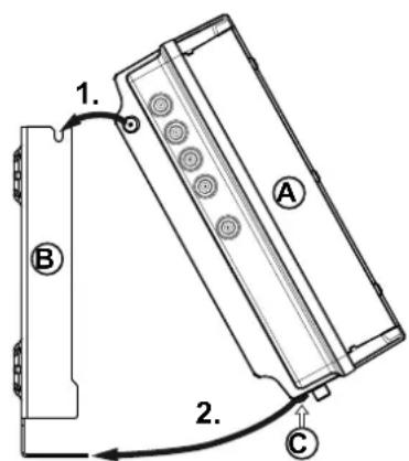
Fig. 3: Insert the head-end
Cabling
- Connect a potential equalisation wire (Cu, ≥ 4 mm 2 ) to the earthing screw; see ⑨ in Fig. 1, P. 3.
- Connect an Ethernet cable 1) to the RJ45 socket on the computer, if required, by means of a switch or router; see Fig. 4, P. 5. The head-end will now function as the master.
-
If a second head-end is present: Connect the second head-end to the first head-end using a USB 2.0 cable (Fig. 4). In this case:
-
The second head-end functions as a slave which is controlled by the master via the USB cable.
- The USB cable must have a type A plug on one end and a type B plug on the other end.
- The plugs must be inserted into the master and slave at the appropriate UFO link interface ports (⑧ in Fig. 1).
- The cascading of two head-ends permits simultaneous access to both devices via a single IP connection, and also allows system functions that apply to both devices, such as common NIT generation incl. LCN.
-
Only head-ends of the same type can be connected by USB.
-
Connect the RF signal cables for the antenna, cable network and output to the head-ends; see ①, ② and ⑤ in Fig. 1, P. 3.
Make sure the input and output cables are correctly assigned to the master and the slave. 2)
- It is recommended that each unused RF input and output is terminated with a 75- Ω resistor such as the EMK 03 from Kathrein.
- Check that the supply voltage matches the particulars on the rating plate, then connect the head-ends to the power supply.
⇒ The head-ends will start up and the status LED will show the operating status 3) .
1) CAT5 or higher is recommended, crossed over for a direct connection to the computer and not crossed over for connections by means of a switch/router.
2) Connect the RF signal cables for the antenna and/or cable network to the master. The RF signal cables regulate the signals which are output from the master. The same applies to the slave, where present. Compilation of the signals is performed by the USW 800.
3) see also LEDs and reset button, P. 3.

flowchart
graph TD
    A["USW 800"] --> B["Switch"]
    B --> C["UFOmini Master"]
    C --> D["Ethernet"]
    C --> E["USB 2.0 cable*"]
    C --> F["Output"]
    G["UFOmini Slave"] --> H["EBC 02/G*"]
    H --> I["Output"]
    J["USB Type A"] --> C
    K["USB Type B"] --> C
    style A fill:#f9f,stroke:#333
    style G fill:#f9f,stroke:#333
    style H fill:#ccf,stroke:#333
    style I fill:#cff,stroke:#333
    style J fill:#ffc,stroke:#333
    style K fill:#ffc,stroke:#333
    style_L["External Device"] --> M["USB 2.0 cable*"]
    style M --> N["EBC 02/G*"]
    note right of M
        * Available as accessory
    end
Fig. 4: Cabling
Configuring
-
Install and start the USW 800 configuration software on the computer.
-
Configure all the head-end parameters as required. In this case:
-
The USW 800 will communicate with the master and detect the slave automatically.
- The current version of the USW 800 and the user guide are available free of charge at www.kathrein-ds.com.
Technical data
| Inputs | ||
| Sat-IF input 4 x F connectors, 75 Ω | ||
| Terrestrial/cable input 1 x F connectors, 75 Ω | ||
| Decoupling dB >25 | ||
| Return loss dB typ. 8 | ||
| Permissible level difference dB max. 12 (an inputs 1, 2, 3, 4) | ||
| DiSEqC TM 1.0 vert./horiz., low/high; sat. pos. (A/B/C/D) | ||
| Switching levels V/kHz | 14/18, 0/22 | |
| Remote feed current for LNB | mA | max. 250 (at F socket no. 3), max. 60 (at F socket nos. 1, 2, 4) |
| Remote feed current for active antenna (5 V) | mA | 100 (at F socket no. 5) |
| Frontend | ||
| DVB-S/-S(2)/-T/-T(2)/-C | 8 x | |
| Frequency grid | MHz | 1 |
| Input level range | dBμV | 60 ... 100 |
| Permissible level difference dB | 20 | |
| Demodulation DVB-S | ||
| Standard | EN 300 421 | |
| Frequency range | MHz | 950 ... 2150 |
| Input symbol rate QPSK | MS/s | 1 ... 45 |
| Code rate (Viterbi) | 1/2, 2/3, 3/4, 5/6, 7/8 | |
| Roll off | % | 35 |
| AFC regulation range | MHz | ± 5 |
| Demodulation DVB-S(2) | ||
| Standard | EN 302 307, TR 102-376 | |
| Input symbol rate QPSK | MS/s | 1 ... 45 |
| Code rate (LDPC) | 1/2, 3/5, 2/3, 3/4, 4/5, 5/6, 8/9, 9/10 | |
| Input symbol rate 8PSK | MS/s | 1 ... 45 |
| Code rate (LDPC) | 3/5, 2/3, 3/4, 5/6, 8/9, 9/10 | |
| Roll off | % | 20/25/35 |
| Demodulation DVB-T (COFDM) | ||
| Standard | EN 300744, NorDig Unified 2.2.1, D-Book 7.0,supports all C.R, G.I, LP and HP streams | |
| Frequency range MHz 50.5 – 858 | ||
| Guard interval 1/4, 1/8, 1/16, 1/32 | ||
| FEC 1/2, 2/3, 3/4, 5/6, 7/8 | ||
| FFT mode 2k, 8k | ||
| Bandwidth MHz 6, 7, 8 | ||
| Constellation QPSK, 16 QAM, 64 QAM | ||
| Demodulation DVB-T(2) (COFDM) | ||
| Standard | EN 302755-V1.31, DVB-T2 Lite compliant,single and multiple PLP support,NorDig Unified 2.2.1, D-Book 7.0 | |
| Guard interval 1/128, 1/32, 1/16, 19/256, 1/8, 19/128, 1/4 | ||
| FEC 1/2, 3/5, 2/3, 3/4, 4/5, 5/6 | ||
| FFT mode 1k, 2k, 4k, 8k, 16k, 32k | ||
| Bandwidth MHz 1.7/5/6/7/8 | ||
| Constellation QPSK, 16 QAM, 64 QAM, 256 QAM | ||
| Demodulation DVB-C | ||
| Standard EN 300429/ITU J.83 Annex A/C | ||
| Frequency range MHz 48 – 858 | ||
| Input symbol rate MS/s | 1 – 7.2 | |
| Constellation | QAM | 4/16/32/64/128/256 |
| MPEG-TS processor | ||
| Channel filter | ||
| PSI-/SI processing | terr. NIT, LCN, PCR correction, CAT | |
| Stuffing | automatic | |
| Modulator | ||
| Output channels | 8 x DVB-T, 2k mode | |
| Constellation | QPSK, 16/64 QAM | |
| Guard interval 1/4, 1/8, 1/16, 1/32 | ||
| Coderate | 1/2, 2/3, 3/4, 5/6, 7/8 | |
| Bandwidth MHz | 5, 6, 7, 8 | |
| RF output | ||
| Output | 1 x F connector, 75 Ω | |
| Frequency range MHz 47 ... 1006 (fine-tuning in 125 kHz steps) | ||
| Frequency range (channel list) | MHz | 47 ... 86/110 ... 862 (setting via channel list) |
| Return loss | dB | 14 (47 MHz) -1.5 dB/oct. |
| Output level | dBμV | 104 (at 862 MHz) |
| Output level setting range | dB | -20 (in 0.5 dB steps) |
| Level stability | dB | ± 0.8 |
| Frequency stability ppm 35 | ||
| MER dB typ. 40 | ||
| Shoulder attenuation dB ≥ 60 (at normal level) | ||
| Spurious emissions dB ≥ 60 | ||
| Test output | ||
| Test socket 1 x F connectors, 75 Ω | ||
| Level relative to the output dB 25 | ||
| System data | ||
| Power consumption W 28 ... 31 | ||
| Permissible ambient temperature °C | 0 ... +45 | |
| Dimensions (H x W x D) | mm | 97 (118) x 350 x 244 (incl. wall support) |
| Weight | kg | approx. 4 |
Repair and Replacement
If, after having read this manual you still have unanswered questions or cannot solve a problem, contact our Customer Service Helpline at +49 731 270 909 70.
For information about repairs, visit our website
https://www.kathrein.com/en/solutions/satellite-reception/support/customer-service/customer-service-for-signal-processing-conversion/.
Furthermore, you can contact our regional service centre:
Regional Service Centre
Disposal/Recycling instructions

Electronic equipment must not be disposed of in domestic waste. According to directive 2002/96/EC OF THE EUROPEAN PARLIAMENT AND COUNCIL of 27 January 2003 on waste electrical and electronic equipment, it must be disposed of professionally. At the end of its service life, take this device for disposal at a designated public collection point.
www.kathrein-ds.com | info@kathrein-ds.com
9364824/c/STD/0619/GB | Subject to change.
KATHREIN Digital Systems GmbH | Anton-Kathrein-Straße 1-3 | 83022 Rosenheim | Germany | Phone +49 731 270 909 70
- Features
- Scope of supply
- Function blocks
- Intended Use
- General safety instructions
- WARNING
- Risk of burns from hot surfaces!
- Transportation and Storage
- Arrangement and function
- Device elements
- LEDs and reset button
- Reset button
- Cascading of head-ends (master/slave)
- Installation and commissioning
- Installation
- CAUTION
- The head-end is mounted as follows:
- Cabling
- Configuring
- Repair and Replacement
- Regional Service Centre
- Disposal/Recycling instructions
Brand : KATHREIN
Model : UFO 83
Category : Digital TV Receiver