
UniFi G3-FLEX - Surveillance Camera Ubiquiti Networks - Free user manual and instructions
Find the device manual for free UniFi G3-FLEX Ubiquiti Networks in PDF.


| Product Type | Indoor/Outdoor Surveillance Camera |
| Brand | Ubiquiti Networks |
| Model | UniFi G3-FLEX |
| Dimensions | 48 x 48 x 45 mm (1.9 x 1.9 x 1.8 in) |
| Weight | 115 g (4.1 oz) |
| Power Supply | PoE (802.3af) / 12V DC (optional) |
| Resolution | 1080p (1920 x 1080) at 30 fps |
| Lens | 2.8 mm, f/2.0, fixed iris |
| Field of View | Horizontal: 102.4°, Vertical: 57.8°, Diagonal: 120.4° |
| Night Vision | IR LED with 15 m range |
| Weatherproof Rating | IPX4 (splash-proof) |
| Operating Temperature | -20 to 40°C (-4 to 104°F) |
| Mount Type | Included wall/ceiling mount |
| Connectivity | 10/100 Ethernet (RJ45), PoE |
| Supported Protocols | UniFi Video, ONVIF |
| Audio | Built-in microphone |
| Storage | NVR or UniFi Cloud Key via Ethernet |
| Reset Button | Yes, pinhole reset |
| Compliance | CE, FCC, IC |
Frequently Asked Questions - UniFi G3-FLEX Ubiquiti Networks
User questions about UniFi G3-FLEX Ubiquiti Networks
0 question about this device. Answer the ones you know or ask your own.
Ask a new question about this device
Download the instructions for your Surveillance Camera in PDF format for free! Find your manual UniFi G3-FLEX - Ubiquiti Networks and take your electronic device back in hand. On this page are published all the documents necessary for the use of your device. UniFi G3-FLEX by Ubiquiti Networks.
USER MANUAL UniFi G3-FLEX Ubiquiti Networks

UniFi®
PROTECT
1080p Indoor/Outdoor IP Camera with
Infrared and 802.3af Support
Model: UVC-G3-Flex
QUICK START GUIDE
Package Contents

G3 Flex Camera Base Mount Pole/Wall
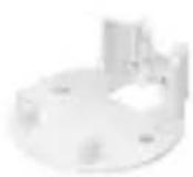

Mount

Outdoor Cover

Security Screw (Qty. 1)

Screws (Qty. 3)

Screw Anchors (Qty. 3)
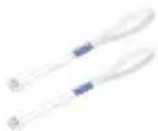
Zip Ties (Qty. 2)
Installation Requirements
• Phillips screwdriver
- Drill and 6 mm (1/4") bit for drywall anchors and 3 mm (1/8") for screws)
- Category 5e (or above) Ethernet cable

Note: When using the Outdoor Cover, use an Ethernet cable without a strain-relief boot on the connector. This will prevent unnecessary tension on the cable ends during installation.

Cable without a strain-relief boot Cable with a strain-relief boot
Outdoor Installation Requirements

IMPORTANT: When installed outdoors, the camera must be installed in the upright position only.
- Mount the camera in the upright position only. Please see diagram below.
- Shielded Category 5e (or above) cabling with drain wire should be used for all outdoor wired Ethernet connections and should be grounded through the AC ground of the PoE.
We recommend that you protect your networks from harmful outdoor environments and destructive ESD events with industrial-grade, shielded Ethernet cable from Ubiquiti Networks. For more details, visit ui.com/toughcable
- Surge protection should be used for all outdoor installations. We recommend that you use two Ethernet Surge Protectors, model ETH-SP-G2, one near the UVC-G3-Flex and the other at the entry point to the building. The ETH-SP-G2 will absorb power surges and safely discharge them into the ground.

Diagram Showing Use of Ethernet Surge Protectors
Before You Begin
The UVC G3 Flex camera is designed to work with Ubiquiti's new integrated management system, UniFi Protect.
UniFi Protect is a flexible and powerful IP video surveillance system that can manage UniFi Protect cameras and the UniFi Protect mobile app. The software is free from all hosting and licensing fees and comes pre-installed on UniFi's Cloud Key Gen2 Plus, model UCK-G2-PLUS.

UniFi Cloud Key Gen2 Plus, model UCK-G2-PLUS
For more information on UniFi Protect, visit us on the web at: unifi-protect.ui.com

Note: The UVC G3 Flex camera will also work with the UniFi Video® 3 controller software.
UniFi Video may be hosted on any of the following:
- UniFi Application Server, model UAS-XG
- UniFi NVR, model UVC-NVR-2TB
• A Linux or Windows computer


UniFi Application Server, model UAS-XG UniFi NVR, model UVC-NVR-2TB

Note: The latest UniFi Video 3 software, for Linux- or Windows-based computers, is available for free download at: ui.com/download/unifivideo
Hardware Overview

Microphone Microphone for recording audio
Camera Lens Lens for viewing/recording video
Light Sensor Sensor for ambient light detection
LED Status indicator for the following:
| LED State Status | |
| Alternating White/Blue | Device is busy; do not touch or unplug it. This usually indicates that a process such as a firmware upgrade is taking place. |
| Steady Blue Connected to Controller; Reset Button Pressed | |
| Flashing Green Disconnected from Controller | |
| Steady White Awaiting adoption | |
Swivel Base Allows you to change the viewing angle of the camera by adjusting left or right. Useful if mounted on a wall or other permanent surface.
Bottom View

Ethernet Port The Ethernet Port is a 10/100 Mbps port used to supply power from a PoE 802.3af-compliant switch to the camera. The switch should be connected to a LAN running DHCP services and the UniFi Video Controller software.
Reset Button The Reset Button is used to reset the camera to factory defaults. Press and hold the Reset Button for more than 10 seconds while the camera is powered on.
Mounting Options

Use the Base Mount by itself to install the G3 Flex camera on a desktop or tabletop. Out of the box, this mount comes preinstalled on the camera.
Use the Base Mount with two screws to install the G3 Flex camera on a wall (vertically).
Use the Base Mount with two screws to install the G3 Flex camera on a solid horizontal surface or ceiling.
Use the Pole Mount with two screws and the Outdoor Cover to install the G3 Flex camera on a wall or flat surface outdoors. The Outdoor Cover is not required for indoor installations.
Use the Pole Mount with two plastic zip ties and the Outdoor Cover to install the G3 Flex camera on an outdoor pole. The Outdoor Cover is not required for indoor pole installations.
Additional Mounts Available
There are two additional mounts available for the G3 Flex: a Ceiling Mount and a Pendant Mount. Each is sold separately.

Use the optional Ceiling Mount, Screw Kit, and Mount Cover to install the G3 Flex camera on a solid horizontal surface or ceiling.

Use the optional Ceiling Mount, Mount Cover, and Back Plate Assembly to install the G3 Flex camera on a drop tile ceiling or horizontal surface where the interior side of the Ceiling Mount is accessible.

Use the Pendant Mount to install the G3 Flex camera onto a fitted 3/4" or 1.5" conduit mount or ceiling pipe.
Installation
The UVC G3 Flex can be installed using one of the following methods:
- Desktop For installing on a flat surface such as a desktop or table/shelf; could be set up for temporary installations.
• Wall/Ceiling For installing in a secure location; used more for stationary or permanent installations. - Pole For installing on a pole (indoor or outdoor).
Proceed to the appropriate section for your installation.

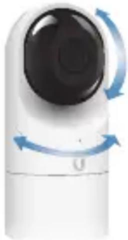
Note: The viewing angle or surveillance coverage of the G3 Flex camera can be changed at any time.
- Tilt the lens up or down for vertical adjustment
- Turn the base left or right for horizontal adjustment
Desktop
- Remove the Base Mount from the base of the camera.

- Insert one end of the RJ-45 cable into the Ethernet Port and the other end into a PoE 802.3af-compliant switch.

- Attach the camera to the Base Mount by lining up the notches with the slots in the base of the camera. Press firmly together until the camera is secure.


Note: Ensure the Ethernet cable is seated in the notch between the Base Mount and base of the camera.
- Place the camera on a desk or table in its upright position.
-
Adjust the viewing angle or surveillance coverage as needed by following these steps:
-
Tilt the lens up or down to adjust the angle vertically
- Turn the camera body left or right to adjust the angle horizontally

Installation complete.

Desktop / Table Install
Wall/Ceiling
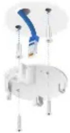
- If the Ethernet cable is coming from the inside of a wall:
a. Drill or cut a hole in the wall and feed the Ethernet cable through the opening.
b. Pull the Ethernet cable forward and slide it through the opening in the mount.
- Use the Screws and Screw Anchors to secure the Base Mount to the wall.
Top Side Down Mounting
or
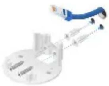
Vertical Upright Mounting
- Connect the Ethernet cable to the Ethernet Port in the base of the camera.

- Attach the camera to the Base Mount by lining up the notches with the slots in the base of the camera. Press firmly together until the camera is secure.
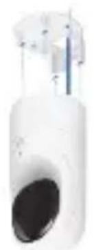
Vertical mounting on ceiling
or
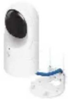
Vertical mounting on a wall
Installation complete.
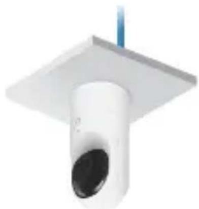
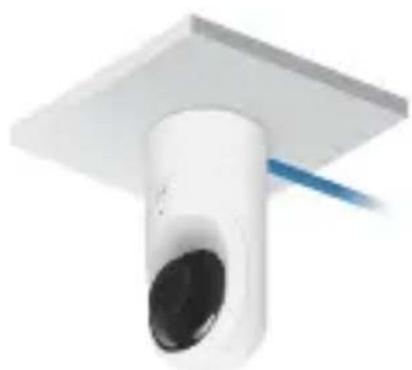
Horizontal Surface / Ceiling with Base Mount


Indoor Wall with Base Mount
Pole

Note: If you are mounting the camera outdoors, it must be installed in the upright position to prevent water from getting into the base of the camera. Use the Outdoor Cover for additional protection from moisture.
- Attach the Pole Mount to a pole using the included Zip Ties.

- Insert and pull an Ethernet cable through the back port opening of the Outdoor Cover.
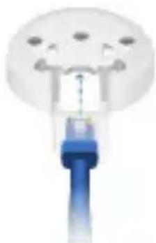

Note: When using the Outdoor Cover, use an Ethernet cable without strain-relief boots on the connector. This will prevent unnecessary tension on the cable ends.
- Connect the Ethernet cable to the Ethernet Port on the G3 Flex camera.

- Attach the camera to the Outdoor Cover by lining up the notches with the slots on the bottom of the camera. Press firmly until the camera snaps on.

- Attach the camera to the Pole Mount:
a. Press the camera against the Pole Mount and line up the notches on the mount with the slots on the bottom of the camera.
b. Slide the camera down onto the Pole Mount until it is secure.
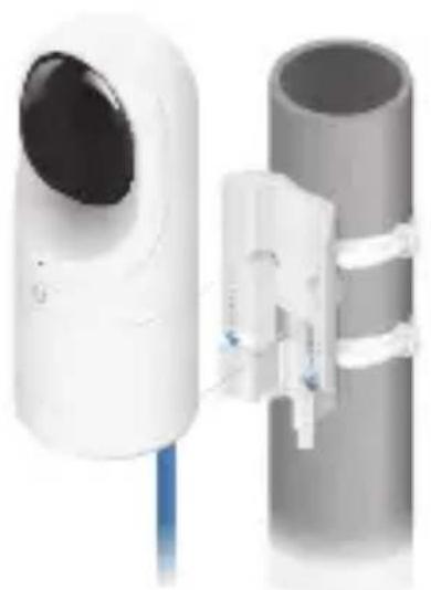

Note: When using the Outdoor Cover, use an Ethernet cable without strain-relief boots on the connector. This will prevent unnecessary tension on the cable ends.
- Use a phillips screwdriver to install the Security Screw through the Outdoor Cover and into the base of the camera. This secures the camera to the mount.

-
Adjust the camera to the desired viewing angle by:
-
Tilting the lens up or down for vertical adjustment
- Turn the camera body left or right to adjust the angle horizontally

Installation is complete.

Pole Mount Install
Setting Up UniFi Protect via App
Download and install the UniFi Protect app to configure the UVC-G3-Flex.



Note: When you first launch UniFi Protect, the app will prompt you to enable Bluetooth and other relevant features necessary to provide the best user experience possible. Please allow these features and permissions to take place for proper app functionality.
- Launch the UniFi Protect app.
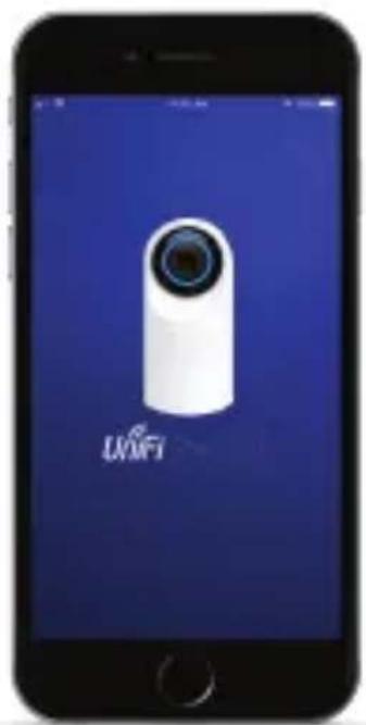
-
Tap the side menu in the upper-left corner of the app to access additional options.
-
Tap Add Cameras to add a new camera.
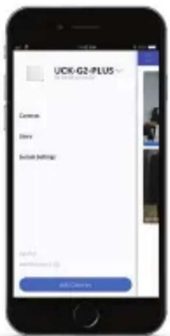

Note: If setting up multiple cameras, UniFi Protect allows you to add more than one camera during the setup process.
- When the Select cameras screen appears, tap each camera in the list you would like to add to your UniFi Protect system. Tap Set up cameras to continue.

- A Name your camera screen appears individually for each camera you selected in step 4. Enter a name for each camera and tap Next, repeating this process until all cameras have been named.

- If necessary, any camera requiring a firmware upgrade will update at this time. Once completed, a live view of each camera will display in the app.


Specifications
| UVC-G3-Flex | |
| Dimensions ∅ 107.5 x 48 x 48 mm | (∅ 4.23 x 1.89 x 1.89") |
| Weight | 170 g (5.99 oz) |
| Sensor 1/2.7" 2-Megapixel HDR Sensor | |
| Lens EFL 4mm / f2.0 | |
| Viewing Angle with Lens Distortion Correction (LDC) LDC Off LDC On | 87.4° (H), 47° (V), 104° (D) 80° (H), 46° (V), 92° (D) |
| Night Mode IR LEDs with Mechanical ICR Filter | |
| Video Compression H.264 | |
| Resolution 1080p FHD (1920 x 1080) | |
| Maximum Frame Rate 25 FPS | |
| Image Settings Brightness, Contrast, Sharpness, Saturation, Noise Reduction, 50/60 Hz | |
| Microphone | Yes |
| Management Interface UniFi Protect; UniFi Video | |
| Networking Interface (1) 10/100 Ethernet Port | |
| Max. Power Consumption 4W | |
| Power Method 802.3af PoE | |
| Power Supply 802.3af PoE Switch Port | |
| Mounting Table, Wall (Indoor/Outdoor), Pole | |
| Operating Temperature | -20 to 50°C (-4 to 122°F) |
| Operating Humidity | 20 to 90% Noncondensing |
Safety Notices
- Read, follow, and keep these instructions.
- Heed all warnings.
- Only use attachments/accessories specified by the manufacturer.

WARNING: Hot Surface. Do not touch.

WARNING: Do not use this product in a location that can be submerged by water.

WARNING: Avoid using this product during an electrical storm. There may be a remote risk of electric shock from lightning.
Electrical Safety Information
- Compliance is required with respect to voltage, frequency, and current requirements indicated on the manufacturer's label. Connection to a different power source than those specified may result in improper operation, damage to the equipment or pose a fire hazard if the limitations are not followed.
- There are no operator serviceable parts inside this equipment. Service should be provided only by a qualified service technician.
Limited Warranty
ui.com/support/warranty
The limited warranty requires the use of arbitration to resolve disputes on an individual basis, and, where applicable, specify arbitration instead of jury trials or class actions.
Compliance
FCC
Changes or modifications not expressly approved by the party responsible for compliance could void the user's authority to operate the equipment.
This device complies with Part 15 of the FCC Rules. Operation is subject to the following two conditions:
- This device may not cause harmful interference, and
- This device must accept any interference received, including interference that may cause undesired operation.
NOTE: This equipment has been tested and found to comply with the limits for a Class A digital device, pursuant to part 15 of the FCC Rules. These limits are designed to provide reasonable protection against harmful interference when the equipment is operated in a commercial environment. This equipment generates, uses, and can radiate radio frequency energy and, if not installed and used in accordance with the instruction manual, may cause harmful interference to radio communications. Operations of this equipment in a residential area is likely to cause harmful interference in which case the user will be required to correct the interference at his own expense.
Industry Canada
CAN ICES-3(A)/NMB-3(A)
This Class A digital apparatus complies with Canadian ICES-003.
CAN ICES-3(A)/NMB-3(A)
CE marking on this product represents the product is in compliance with all directives that are applicable to it.

RoHS/WEEE Compliance Statement

English
European Directive 2012/19/EU requires that the equipment bearing this symbol on the product and/or its packaging must not be disposed of with unsorted municipal waste. The symbol indicates that this product should be disposed of separately from regular household waste streams. It is your responsibility to dispose of this and other electric and electronic equipment via designated collection facilities appointed by the government or local authorities. Correct disposal and recycling will help prevent potential negative consequences to the environment and human health. For more detailed information about the disposal of your old equipment, please contact your local authorities, waste disposal service, or the shop where you purchased the product.
Deutsch
Declaration of Conformity
English Hereby, UBIQUITI declares that the radio equipment type UVC-G3-Flex is in compliance with Directive 2014/53/EU. The full text of the EU declaration of conformity is available at the following internet address: www.ui.com/compliance
Community community.ui.com
Downloads downloads.ui.com

www.ui.com



- PACKAGE CONTENTS
- INSTALLATION REQUIREMENTS
- OUTDOOR INSTALLATION REQUIREMENTS
- BEFORE YOU BEGIN
- HARDWARE OVERVIEW
- BOTTOM VIEW
- MOUNTING OPTIONS
- ADDITIONAL MOUNTS AVAILABLE
- INSTALLATION
- DESKTOP
- WALL/CEILING
- POLE
- SETTING UP UNIFI PROTECT VIA APP
- SAFETY NOTICES
- ELECTRICAL SAFETY INFORMATION
- LIMITED WARRANTY
- UI.COM/SUPPORT/WARRANTY
- COMPLIANCE
- FCC
- INDUSTRY CANADA
- CAN ICES-3(A)/NMB-3(A)
- ROHS/WEEE COMPLIANCE STATEMENT
- ENGLISH
- DEUTSCH
- DECLARATION OF CONFORMITY
Brand : Ubiquiti Networks
Model : UniFi G3-FLEX
Category : Surveillance Camera