DC205 - Measuring equipment SRS - Free user manual and instructions
Find the device manual for free DC205 SRS in PDF.


| Product Type | Precision DC Voltage Source |
| Brand | SRS (Stanford Research Systems) |
| Model | DC205 |
| Voltage Range | 0 to ±100 V |
| Resolution | 1 mV (20-bit DAC) |
| Accuracy | ±0.005% of setting + 1 mV |
| Output Noise | < 10 µVrms (0.1 Hz to 10 Hz) |
| Maximum Output Current | 50 mA |
| Remote Interfaces | GPIB (IEEE-488) and RS-232 |
| Display | 6-digit LED, 2-line alphanumeric |
| Dimensions | 214 mm × 133 mm × 374 mm (W × H × D) |
| Weight | 4.5 kg |
| Power Supply | 100-240 VAC, 50/60 Hz, 40 VA |
| Operating Temperature | 0°C to 40°C |
| Storage Temperature | -20°C to 70°C |
| Warm-Up Time | 1 hour to rated accuracy |
| Calibration Interval | 1 year |
| Main Functions | Precision voltage source, constant voltage output, remote programming, scan mode, ramp, and arbitrary waveform generation |
| Safety | Overload protection, reverse polarity protection, CE marked |
| Spare Parts & Repairability | Fuses, power supply module; repairable by qualified service center |
| Maintenance & Cleaning | Wipe with dry cloth, avoid solvents; periodic calibration check |
Frequently Asked Questions - DC205 SRS
User questions about DC205 SRS
0 question about this device. Answer the ones you know or ask your own.
Ask a new question about this device
Download the instructions for your Measuring equipment in PDF format for free! Find your manual DC205 - SRS and take your electronic device back in hand. On this page are published all the documents necessary for the use of your device. DC205 by SRS.
USER MANUAL DC205 SRS
PrecisionDCVoltageSource
DC205

Stanford Research Systems
Certification
StanfordResearchSystemscertifiesthatthisproductmetitspublishedspecificationsatthetime ofshipment.
Warranty
ThisStanfordResearchSystemsproductiswarrantedagainstdefectsinmaterialsandworkmanshipforaperiodofone(1)yearfromthedateofshipment.
Service
Forwarrantyserviceorrepair, thisproductmustbereturnedtoaStanfordResearchSystems authorizedservicefacility.ContactStanfordResearchSystemsoranauthorizedrepresentative beforereturningthisproductforrepair.
Informationinthisdocumentissubjecttochangewithoutnotice.
Copyright ©StanfordResearchSystems, Inc., 2019. All rights reserved.
StanfordResearchSystems, Inc.
1290-DReamwoodAvenue
Sunnyvale, CA94089USA
Phone:(408)744-9040•Fax:(408)744-9049
www.thinkSRS.com•e-mail:info@thinkSRS.com
PrintedinU.S.A.Documentnumber9-01745-903
Contents
GeneralInformationv
SafetyandPreparationforUse......v
Symbols......vi
Notation......vii
Warnings......vii
Specifications......viii
1GettingStarted1-1
1.1 Howtousethismanual....1-2
1.2Preliminaries ......1–2
1.2.1 Equipmentneeded ....1-2
1.3Firstexample: turningontheinstrument.....1-2
1.4Userinterface....1-4
1.5Instrumentsettings 1-5
1.5.1 Sense....1-5
1.5.2 Isolation 1-7
1.5.3 Scanning 1-8
1.6Interlock 1-10
2Operation
2-1
2.1 Navigating the front panel 2-2
2.1.1 Power....2-2
2.1.2 Range....2-5
2.1.3 Select/Adjust 2-5
2.1.4 NumericEntry 2-6
2.1.5 Sense....2-7
2.1.6 Config 2-7
2.1.7 Scan....2-8
2.1.8 Output....2-9
2.1.9 Status 2-9
2.1.10 SourceOut 2-10
2.2 Scanning 2-11
2.2.1 Overview of scanning 2-11
2.2.2 Scanterminology......2–11
2.2.3 Arming scans 2-12
2.2.4 Triggeringscans....2-13
2.2.5TRIGInandBUSYOut......2-13
2.2.6 Endingorcancellingscans......2–14
2.3Errormessages....2-15
2.3.1Messagesatpoweron....2-15
2.3.2Fieldcalibration....2-16
2.3.3 Scanning....2-16
2.3.4 Interlock....2-16
2.3.5 Unexpected resets......2–17
3Architecture3-1
3.1Overview....3-2
3.2 Voltage reference 3-3
3.3Digitaltoanalogconverter ....3-3
3.4Amplifiers....3-4
3.4.1 High-rangeamplifier ....3-4
3.4.2 Low-rangeamplifier ....3-4
3.5Remotesensing....3-4
4RemoteOperation
4-1
4.1Indexofcommands....4-2
4.2Alphabeticlistofcommands....4-4
4.3Introduction 4-6
4.3.1 Interfaceconfiguration .....4-6
4.3.2 Isolation and computernoise .....4-6
4.3.3Buffers 4–6
4.4Commands....4-7
4.4.1 Commandsyntax ......4–7
4.4.2 Notation....4-8
4.4.3Examples....4-8
4.4.4Configurationcommands ......4-9
4.4.5Settingcommands ....4-10
4.4.6 Scancommands ....4-11
4.4.7 Setupcommands ....4-14
4.4.8Interfacecommands ....4-14
4.4.9Statuscommands....4-18
4.5Statusmodel....4-22
4.5.1Statusbyte(SB) 4-23
4.5.2Servicerequestenable(SRE)......4-23
4.5.3 Standardeventstatus(ESR)......4–24
4.5.4DCsourcestatus(DCCR/DCEV) .....4-24
5FieldCalibration
5-1
5.1 Introduction to field calibration.....5-2
5.2 Calibrationmethod....5-2
5.3Equipmentneeded....5-3
5.4Detailedprocedure....5-3
5.5 Followingfieldcalibration....5-5
5.6Restoringthefactorycalibration....5-6
6PerformanceVerification6-1
6.1 Introduction to performance verification.....6-2
6.2Equipmentneeded....6-2
6.3Verificationprocedure......6-2
6.4Performancetestrecords......6-3
A FuseandacLine
A.1PowerEntrymodule ......A-1
A.2acvoltageselector ......A-1
A.3Fuseinstallation ......A-3
A-1
GeneralInformation
SafetyandPreparationforUse

WARNING
Dangerousvoltages, capable of causing injury or death, are present in this instrument. These voltages can persist from any minutes after acpower is removed. Donotremovethe product covers or panels. Donotapply power or operatethe product without all covers and panels in place.
AClinevoltage

CAUTION
TheDC205PrecisionDCVoltageSourceoperatesfroma100V,120V, 220V-230V, or 240V nominal ac power source having a line frequencyof50Hzor60Hz. Beforeconnectingthepowercordtoa powersource,verifythattheLINEVOLTAGESELECTOR,located intherearpanelpower-entrymodule,issetsothatthecorrectacline voltagevalueisvisible.Foroperationwith230Vacpower,theLINE VOLTAGE SELECTOR should be set to 220V.
TheDC205PrecisionDCVoltageSourcewillbedamagedifoperatedwiththeLINEVOLTAGESELECTORsetforthewrongacline voltage,orifthewrongfusesareinstalled. Verifythatthecorrect linefusesareinstalledbeforeconnectingthelinecord. Usetwo(2) metric size 5×20 mm fuses. For 100 V/120 V, use 1 A fuses; for 220 V-230V/240V,use0.5Afuses.SeeappendixAfordetailedinstructions.
Linecord
The DC205 Precision DC Voltage Source has a detachable, three-wire power cord for connection to the powersource and to a protective ground. The chassis of the instrument is connected to the outlet ground to protect against electrical shock. Always use an outlet which has a properly connected protective ground.
Service
The DC205 Precision DC Voltage Source does not have any user serviceable parts inside. Refer service to a qualified technician.
Donotinstallsubstitutepartsorperformanyunauthorizedmodificationstothisinstrument.Contactthefactoryforinstructionson how to return the instrument for authorized service and adjustment.
SymbolsyoumayFindonSRSProducts
| Symbol Description | |
 | Alternating current |
 | Caution - risk of electric shock |
 | Frame or chassis terminal |
 | Caution - refer to accompanying documents |
 | Earth (ground) terminal |
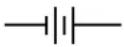 | Battery |
 | Fuse |
| On (supply) | |
| Off (supply) | |
Notation
The following notation will be used throughout this manual.
WARNING
A warning mean that injury or death is possible if the instructions are not obeyed.
CAUTION
Acautionmeansthatdamagetotheinstrumentorotherequipment is possible.
Typesetting conventions used in this manual are:
- Front-panelbuttonsaresetas[Button]
- Front-panelknobsaresetas Knob
- Front-panelindicatorsaresetasOverload
- Remotecommandnamesaresetas*IDN?
- LiteraltextotherthancommandnamesissetasOFF
Remotecommandexampleswillallbesetinmonospacedfont. In these examples, datasentbythehostcomputertotheDC205areset asstraightteletypefont, whileresponsesreceivedbythehost computerfromtheDC205aresetasslantedteletypefont.
Warnings
The DC205isequiped with as safety interlock, which must be closed to energizethe ± 100V output range of the instrument. Details on the safety interlock can be found in section 1.6 on page 1–10.
WARNING
When using banana-to-BNC adapter hardware with the DC205, the ground tab of the adapter must be oriented to the black LO terminal, and the black LO terminal must be grounded. This ensures that the exposed BNC shield parts are at a safe electrical potential. Use of banana-to-BNC adapters is not recommended when the safety interlock is closed or the DC205 is operated on the ± 100V range.
Specifications
Allperformancespecificationsafter2hourwarm-upat23 ambient, unless otherwise specified.
° C±1 ° C
Output
| RangeFullResolutionMaxTimeSettling scale(1ppm)currentconst. | time | ||||
| VµVmAµsms | |||||
| 1V±1.0100001 | 50160 | 50 | |||
| 10 V | ±10.100 00 | 10 | 50 | 160 | 50 |
| 100 V | ±101.000 0 | 100 | 25 | 400 | 100 |
+ Timerequiredtosettleto63%offinalvalue
‡ Timetosettleto99.999%offinalvalue
Settlingtimesmeasuredforfull-scalestepinto10MΩload.
Accuracyandstability
| Range | Accuracy(23°C±1°C) | Stability(±1°C) | ||
| 24h | 90day * | 1year * | 24 h | |
| ±(ppmsetting+μV) | ||||
| 1 V | 7 + 2 | 12 + 6 | 25 + 10 | 1 + 1 |
| 10 V | 7 + 12 | 12 + 20 | 25 + 20 | 1 + 3 |
| 100 V | 8 + 120 | 12 + 200 | 25 + 200 | 1 + 20 |
* preliminary
Noiseanddrift
| Range | Temperature coefficient | Noise (typical) | |
| 0 °C-40 °C±( ppm setting + μV)/°C | (0.1-10) Hz10Hz-100kHzμVrms | ||
| 1 V | 1 + 1 | 0.5 | 9 |
| 10 V | 1 + 2 | 1.5 | 12 |
| 100 V | 1 + 15 | 12 | 50 |
RemotelInterfaces
| RS-232DB-9connector,baudrates9600,19200,38400,57600,and115200 |
| USBUSBtypeBreceptacle;serialportemulation,115,200baud |
| OpticalfiberConnectiontoSX199OpticalInterfaceController.Provides isolatedconnectivitytoGPIB,RS-232,andEthernet. |
| InterlockTwo-positionEuroblock-styleterminalblock,0.150'' (3.81mm), 180° freehanging(in-line) |
General
| ParameterSpecification | |
| Temperature0 | °Cto40 °C,non-condensing |
| Power | < 20 W, 100/120/220/240 VAC, 50/60 Hz |
| Dimensions8.3 | "W×3.5 " H×13 " D |
| Weight10lbs | |
| Fuse | two(2)metricsize5×20mm |
1GettingStarted
Thischapterprovidesstep-by-stepinstructiontogetstartedquickly withtheDC205PrecisionDCVoltageSource.Refertochapter2for amorecompleteintroductiontotheDC205.
InThisChapter
1.1 Howtousethismanual......1-2
1.2 Preliminaries....1-2
1.2.1 Equipmentneeded ....1-2
1.3Firstexample:turningontheinstrument .....1-2
1.4Userinterface ......1-4
1.5Instrumentsettings....1-5
1.5.1Sense....1-5
1.5.2Isolation ....1-7
1.5.3 Scanning ..... 1–8
1.6Interlock 1-10
1.1 Howtousethismanual
Twopossible starting points are available to new users of the DC205. Those how want to begin with an overview to the function all out of the instruments should turn to Chapter 2.
UserswhoprefertojumpinandbeginusingtheDC205firstshould continuewiththisChapter,whereaseriesofstep-by-stepprocedures aregiventoverifythebasicperformanceoftheinstrument.Thiswill alsoprovideaquickintroductiontotheDC205andhowitisoperated.
Chapter3providesdetaileddiscussionsofthesubsystemswithin theDC205.Technicaldetails,suchascircuittopologyandinput protectionforremotesensing,canbefoundhere.
Chapter4discussesremoteoperationoftheDC205overanyofthe threeeremoteinterfaces:USB,RS-232,andopticalfiber.
Chapter5detailstheprocedureforadjustingthecalibrationofthe DC205inthefield.
Chapter6giveamethodforverifyingtheoutputvoltageaccuracy of the DC205, and containstablestocopyforrecordingtestresults.
1.2 Preliminaries
The following sections provide step-by-step instructions for verifying the basic operation of the DC205. In addition to confirming proper operation, it provides a good introduction to operating the current source.
1.2.1 Equipmentneeded
Toperformallthestepsdescribedinthischapter,youwillneed:
- acollectionofstackingbananaplugtestleads,
- aprecisionvoltmeterwithatleast6digitsresolution,
- aBNC50Ω terminator,
- adualbanana-to-BNC(banana-male,BNC-female)adapter.
1.3Firstexample:turningontheinstrument
ThissectiondescribestheinitialstepsforfirstoperatingtheDC205. PleasepayspecificattentiontotheAClinevoltageselectorsetting.

CAUTION
- Verifytherear-panelpowerentrymoduleisproperlyconfiguredforthelinevoltageinyourregion. Applyingpower
withimpropersettingofthelinevoltageselectorwillresultin significantdamagetotheDC205.
-
PlugtheAClinecordintotherear-panelpowerentrymodule, and then into agroundedwalloutlet.
-
Using banana-plugtestleads, connect the DC205 OUTPUT terminals (HI and LO) to the voltmeter input terminals (HI and LO). Turn on the voltmeter and set it to DCV, Autorange.
4.Restorethefactorydefaultsettingsbyholdingdownthe backspace[]buttonwhileturningthepoweroffandon again. This will perform the power-on reset, and return the instrument to its factory default state. After several seconds, the display will show dEFCF9 , then the instrument's serialnumber,and then *0.000000.
-
Key in the value 1.000000 V. Start by pressing the [1] and notice the display shows the polarity indicator + and digit 1 are shown. Also, the Pending indicator begins blinking, indicating thenumericvalue is awaitingentry.
-
Try pressing another digit, such as [3]. Note the value is not added to the display, as the implied value (13) is out of range for the current setting. Then press the decimal point button, [.], and then press [0] three times. The display should show * 1.000 and Pending shouldstillbeflashing.
-
Now press the [7] digit. The display will show *1.0007. Pressthe[] button to erasethe. 7
-
Press the [Enter/Start]. The Pending indicator should go dark, and the display now shows * 1.0000000 Themulti-meters should not yet show anysteady reading.
-
Finally, press the OUTPUT [On/Off] button. The On indicator shouldilluminate, and themultimeters shouldnowshowa readingverycloseto+1.00000V.
-
Allow the unit to warm up for 2 hours for full specified performance. Warm up is not needed to test basic functionality.

1.4Userinterface
ThissectionexplorestheDC205front-panelinterface,anddemonstratesthedifferentmethodsforenteringormodifyingthevoltage setting.
-
If the OUTPUT is still On, turn it off by pressing the [On/Off] button.
-
ChangetheRANGEto±10Vbypressing[Range]once.Set thevoltageto0bypressing[0]andthen[Enter/Start].Enable theoutputbypressingOUTPUT[On/Off].Thedisplayshould show. * 00.000000
3.Pushthe knobin,thenrelease.leastsignificantdigitshould begintoblink.Nowslowlyturnthe knobclockwise.The DC205willclick,andtheleastsignificantdigit(tensofmicrovolts)willbeginincrementing.Continueturningtheknobuntil thedisplayshows * 00.00020
- Press the SELECT/ADJUST[◀] buttontwotimes. Noticethat with each press, the blinking digit moves one position to the left. Now slowly turn the knob for 3 more clicksclockwise. The display should now show *00.00320 and the multimeters should show the same voltage.
5.Nowcleartheoutputsettingbypressing[0]and[Enter/Start]. The display returns to * 00.000000, but notice the millivoltsdigitisstillblinking.Nowpressthe[▲]buttonthree times. The display should now show * 00.00300. Turn the knob counterclockwise for 5 clicks. The display shouldnowshow.andthe. (nullvolt position)isstillblinking.
- Press the [Cancel] button—now the blinkings should stop. Turn the knob clockwise, without pushing it in. Not that there are clicks, and these setting does not change.
ThisbriefexercisedemonstratedtheentrymodesfortheDC205,includingthenotionofactiveediting(indicatedbytheblinkingdigit),andtheuseofthe[Cancel]buttontoreturntothedisplay-idlestate. Notethatthe[▲]and[▼]buttonsprovideessentiallythesamefunctionalityasthe knob.
1.5Instrumentsettings
ThissectionwilldemonstratethebasicconfigurationsoftheDC205.
1.5.1 Sense
The SENSE setting selects 2-wire or 4-wire (remotesensing) for the voltagesource circuitry.
- If the OUTPUT On indicator slit, disable the DC205 OUTPUT bypassing the [On/Off] button.
- Connectapairofbananatestleadsfromtheredandblack SENSEterminalsontheDC205totheinputHI,LOWterminals onthemultimeter.
- Connectasecondpairofbananatestleadsfromtheredand blackOUTPUTterminalsontheDC205,connectingtheother endofthesetestleadstothebackofthecorrespondingstackablesocketsonthebananaleadsatthemultimeter. Besureto connectHItoHI,andLOWtoLOW.
- If not already configured, press the [Range] button repeatedly until the ±1 V range is selected. Press [Float/Ground] to select Ground, and press [2or4Wire] to select 2-wire.
5.Plugthebanana-to-BNCadapterintothebackbananaleadsat themultimeter(seethefollowingphoto). Besuretoalignthe GroundtaboftheadapterwiththeLOWsidebananaleads.
WARNING
Wheneverusingabanana-to-BNCadapter, theoperator must ensure that (a) the ground tab of the adapter is oriented to the LO (black) terminal, and (b) that the LO terminal is grounded. Failure to follow this procedure can result in hazardous voltages being accessible on the outer shield of a user-provided BNC cable or connector.
-
Press[1] and [Enter/Start] to program the setting to 1.000000V. Press[On/Off] to enable the output. Verify them ultimeter displaysavoltage every closeto 1.000000V.
-
Use the SELECT/ADJUST buttons or the knob to adjust the DC205 until them ultimeter display exactly 1.000000V, with a minimum of 100μV resolution.
-
Attach a 50Ω BNC terminator to the banana-to-BNC adaptor. Verify that the multimeter display drops by at least one or two millivolts (the actual drop will depend on the length and wire gauge of your bananatest leads).
-
Now, press the [2 or 4 Wire] button. Verify that the 4-Wire indicatorandtheSENSEindicatorbothbecomeilluminated.
-
Themultimeters should again be displayed exactly 1.000000 V, with a minimum of 100 µV resolution.

This exercise demonstrates the function of remote sensing in the DC205. When operated in simple 2-wire mode, the set output voltage is controlled internally. When significant load is presented (in this case, 50Ω ), a current flows from the voltage source through the circuit created by the output leads. In this case, with 1V across 50Ω , a total of 20mA flow through the output and the bananatest leads. Even 10mΩ of lead resistance in this case will lead to a 200µV potential drop.
By enabling remote sensing in the 4-Wire mode, the DC205 controls the potential as measured by these sense leads. By carefully arranging the SENSE wiring to not carry any of the load current, the desired output voltage is applied at the point of interest (in this case, at the multimeter input terminals).
1.5.2 Isolation
The CONFIGsettingselectswhethertheoutputcircuitryofthe DC205isreferencedtochassisgroundorfloating.
- If the OUTPUT On indicator is lit, disable it by pressing the [On/Off] button.
- ConnectapairofbananatestleadsfromtheredandblackOUTPUTterminalsontheDC205totheinputHI,LOWterminalsonthemultimeter.
- Press the [Range] button to select ±1 V. Press the [Float/Ground] buttontoselectFloating.Press[1]andthen[Enter/Start]toset thedisplayto. * 1.000000
4.Pressthe[On/Off]buttontoenabletheoutput.Verifythat +1.0000Vappearsonthemultimeter.
- Connectanotherbananatestleadfromthegreen chassis ground terminal on the DC205 front panel to the red HI banana lead at theDC205.
Noticethatthemultimeterstilldisplays+1.0000V, even though the HI terminalisnow connected to chassisground. The output of the DC205 is configured to float; by grounding the HI terminal with the bananalead, the LOW terminal is now at -1.0000V with respect to ground.
6.Nowpressthe[Float/Ground]buttontoselectGround.
Now notice that the multimeter display has dropped to a value near0V(probablyafewmillivolts). Also,theredOverload indicator on the DC205 is illuminated. With the DC205 in Groundmode,theLOWterminalisinternallytiedto ground. By grounding the HI terminal, the outputs are shorted, causing Overloadtoilluminate.
- Carefully remove the grounded lead from the back of the banana cable at the HI terminal. The Overload indicator should turnoff, and themeters should measure voltagecloseto1.0000V.
1.5.3 Scanning
InadditiontogeneratingastableDCvoltage,theDC205isalsoable tocreatelinearsweepsoftheoutputvoltage.Thisexamplewill demonstrateonesuchsweep.
- If the OUTPUT On indicator slit, disable it by pressing the [On/Off] button.
- ConnectapairofbananatestleadsfromtheredandblackOUTPUTterminalsontheDC205totheinputHI,LOWterminalsonthemultimeter.
- Press the [Range] button to select ±1 V. Press the [Float/Ground] buttontoselectGround.Pressthe[2or4Wire]buttontoselect 2-wire.
4.Brieflypressthe[SetupArm]button,enteringtheSCANsetup mode.Thedisplayshouldnowshow.Press[▲],9.1 changingthedisplayto.Press[▼]foreturnthe scanrangeselectionto r n 9. tPress[▶]once. - Thedisplaynowshowsthe beginningvoltageforthescan, indicated with the b at the left side of the display. Key in thevalue[0],[.],[1],andthenpress[Enter/Start]. Thedisplay shouldshow *b 0.100000Press[▶]again.
- Thedisplaynowshowstheendingvoltageforthescan, indicatedwiththe Eattheleftsideofthedisplay.Keyinthevalue [0], [.], [8], and press [Enter/Start]. The display should now show *E0.8000000Press[▶]again.
- Thedisplaynowshowsthetimedurationforthescan, indicated by the tattheleftsideofthedisplay.Keyinthevalue [1] [0] and press [Enter/Start], to set the scan to 10 seconds. The display should now show t0010.05. Press [▶] again.
- The display now shows the scan shape setting, indicated by the Sh at the left side of the display. The two choices are Sh on Ed ir (aunidirectional ramp), and Sh up - dn (a bidirectional ramp). Press [▲] and [▼] to switch between these options. Leave the setting at Sh on Ed ir, and then press[▶]again.
- The display now shows the scan repeat mode, indicated by the CYCLE attheleftsideofthedisplay. Thetwochoices
are(asingscan) and E CYCLE inF (repeatinguntilcancelled).Press[▲]and[▼]toswitchbetween theseoptions.Leavethesettingat,and CYCLE onE thenpress[▶]again.
-
Thedisplaynowshowsthescandisplaymode, indicated by theathefsideofthedisplay. Thetwochoicesare d, SP on (displayisupdatedinnearrealtimeduring thescan) and (displayislestaticduring the scan). Press[▲] and [▼] to switch between these options. Leave the setting at d, SP on, and then press [▶] again.
-
The display will be back to the 9.1 setting. Press the [◀] tonavigatebackwards, tothe ,5P on setting. You can navigate forward and backward through the scan parameters with the [◀] and [▶] select buttons. Note, however, that any timethescanrangeismodified, both the beginning and ending scanf voltagesareresettozero.
Press [Cancel] to exit SCAN setup mode. Set the output voltage0.5Vbypressing[0],[.],[5],[Enter/Start].Thenturn the output On by pressing [On/Off]. The multimeter should displayavalue closeto0.5000V.
-
Now press and hold the [Setup Arm] button for at least 2 seconds. The display will briefly show SCAnrdy, and thenshow *0.100000 whichisthestarting voltage forthescan. Also,theArmedindicatorcomesontoshowthat the scan is armed, and Pending is steadily illuminated. Press the [Enter/Start] button to start the scan.
-
While the scan is running, notice that the multimeter and the DC205display are both smoothly sweeping from 0.1 V to 0.8 V. After 10 seconds, the scan should end and the output voltage settles at 0.8 V.
1.6Interlock

WARNING
TheDC205isdesignedwithasafetyinterlockcircuitthatmust beactivatedforthe±100Voutputrangetobeenabled.Theinterlockisintendedtosupportsafeoperationofthisinstrument inatestsystem.Bypassingtheinterlockcanleadtoahazardouscondition,possiblyexposingtheoperatortodangerous electricalpotentialsupto±100V,capableofcausinginjuryor death.
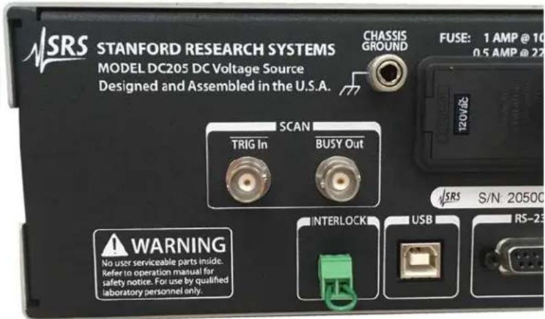
Figure1.1:TheDC205rearpanel,shownwithaninterlockdefeatplug.
Forsafety, the ± 100 V range can only be enabled when the interlock signal is closed. Toclosetheinterlock, alow impedance circuit must be established between pins 1 and 2 of therear-panel INTERLOCK header. Amating terminal block plots provided with the DC205.
When the interlock is closed, the front panel Interlock indicator will be illuminated. The interlock must be closed to enable OUTPUT on when the RANGE is ± 100V .
If the interlock becomes open while operating on the ± 100V range with OUTPUTOn, then the output will trip off and the message
Err Intloc will bedisplayed. This message will persist until the user presses [Cancel] or another button, or sends any remote command data.
Note that the ±1V and ±10V range settings can be enabled independentofthewhethertheinterlockisclosed.
2Operation
ThischapterprovidesabasicoverviewoftheDC205PrecisionDC VoltageSource.
InThisChapter
2.1 Navigating the front panel......2-2
2.1.1 Power....2-2
2.1.2Range....2-5
2.1.3Select/Adjust....2-5
2.1.4NumericEntry......2-6
2.1.5Sense....2-7
2.1.6Config....2-7
2.1.7Scan....2-8
2.1.8Output....2-9
2.1.9Status....2-9
2.1.10 SourceOut....2-10
2.2Scanning......2-11
2.2.1 Overviewofscanning......2-11
2.2.2 Scanterminology....2-11
2.2.3Armingscans ......2–12
2.2.4Triggeringscans....2-13
2.2.5TRIGInandBUSYOut......2-13
2.2.6Endingorcancellingscans .....2-14
2.3Errormessages....2-15
2.3.1Messagesatpoweron 2-15
2.3.2Fieldcalibration....2-16
2.3.3 Scanning....2-16
2.3.4Interlock 2-16
2.3.5 Unexpected resets ......2-17
2.1 Navigatingthefrontpanel
ThefrontpaneloftheDC205isorganizedintodistinctfunctional sections. ThefrontpanelisshowninFigure2.1,below.

Figure2.1:TheDC205frontpanel.
2.1.1 Power
When the DC205 is connected to an AC powersource, the power supply will initially be instand by mode, indicated by the Standby indicator in the POWER section. Toturn the DC205 on press and hold the [] button until Standby is no longer lit, and therest of the display comes on.

Initially,theDC205firmwareversionisdisplayed,followedbythe unit'sserialnumber,andthentheunitbeginsoperatingnormally.Thereareseveralspecialpower-onmodesaccessiblebyholdinga secondbuttondepressedwhilepressing[].

Figure 2.2: Power-on special modes on the DC205 front panel.
2.1.1.1 Power-onfactoryreset
Pressingandholdingthebackspace[ ]buttonwhileturningon powerwillrestorethefactorydefaultconfigurationoftheDC205.
The unit will display the message CFG to indicate the defaultconfigurationisbeingrestored.
In addition to putting the instrument into the default configuration (see *RST), the DB-9 RS-232 baud rate is set to 9600. Note that Field calibrationdataisnot affectedbypower-onfactoryreset—torestore factorycalibration,seethe"Restore calibration"mode,below.
2.1.1.2Field calibration
Pressing and holding the [+/-] button while turning on power will place the instrument in Field Calibration mode. You can read more aboutfieldcalibrationoftheDC205inchapter5(page5–1).
2.1.1.3 Restorecalibration
Pressingandholdingthe[Cancel]buttonwhileturningonpowerwill bringtheinstrumentintoRestoreFactoryCalibrationmode.The displaywillshow.Thiswiller&sonfield calibrationdatastored,andrestorethefactorycalibrationvalues.
Toconfirmrestoringthefactorycalibration,pressthe[Enter/Start] button. Thedisplaywillthenshow.Theinstrument willthenperformaninternalreset,oreturntonormaloperation.
The message 8 will appear on the display indicating the firmware was reset; simply press [Cancel] to clear the message andresume operation.
To cancel from Restore Factory Calibration without erasing field calibration data, press the [Cancel] button. The DC205 will then enter normaloperation.
2.1.1.4 Baudrate
Pressingandholdingthe[SetupArm]buttonwhileturningonpower willcausetheDC205baudratetobedisplayedonthenumericdisplay. Use the [▲] and [▼] buttons to select between 9600, 19200, 38400, 57600, and 115200 baud. Press [Cancel] to resume normal operation.
Thenewbaudrateissaved, and retained through powercycles.
2.1.1.5Keyclicks
Pressing and holding the [0] button while turning on power will cause toggle whether button presses generate "key click" sounds during operation. This can also be changed remotely with the KCLK command(section4.4.7, page4–14).
Pressing and holding the [1] button while turning on power will cause to toggle whether button presses generate audible alarms sounds in response to errors during operation. This can also be changed remotely with the ALRM command (section 4.4.7, page 4–14).
2.1.2Range
The RangebuttoncontrolstheDC205outputrangesetting. Pressing [Range] advances through the settings ±1 V, ±10 V, and ±100 V. Pressing [Range] while in the ±100 V setting cycles back to ±1 V.

Changingtherangeisonlypossiblewhentheoutputisdisabled. Pressing[Range]whiletheoutputisOncausestheErrorindicator tobrieflylight,andtheDC205willbeep.
Notethatwhileanyrangemaybeselectedsolongastheoutputis off, it is not possible to enable the output on the ±100 V range unless the safetyinterlockisclosed.
2.1.3Select/Adjust
TheclusterofarrowbuttonsintheSELECT/ADJUSTblockprovides aflexibleinterfacetocontrollingthevoltagesettingoftheDC205.
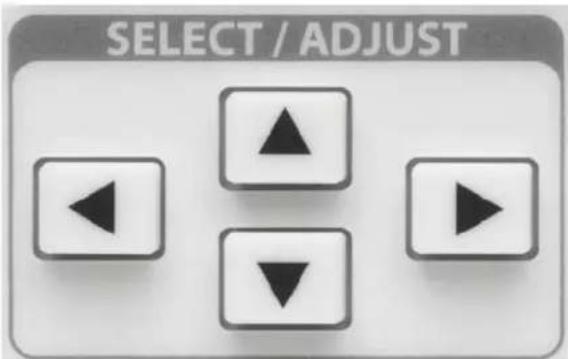
Whenthedisplaysinthe"display-idle"state,thevoltagesetting willbedisplayedandnodigitwillbeblinking.Pressinganyofthe fourarrowbuttonsoncewillcausethemost-recentlyselecteddigit tobeginblinking,indicatingthefocusforeditingthesetting.
Onceadigitisblinking,thatplacevaluecanbeincremented(ina signedsense)bypressing[▲],anddecrementedbypressing[▼].That digitvaluecanalsobeincrementedbyturningthe knobclockwise,
ordecremented by turning the knob counterclockwise. Theselected digitplace can be changed by pressing either the [◀] or [▶].
Theblinkingfunctioncanbecancelled,andthedisplayreturnedto thedisplay-idlestate,bypressing[Cancel],orbybrieflypressingthe knobinwards.Whennodigitisselected(blinking),turningthe knobwillhavenoeffect.
Thearrowbuttonsarealsousedwhennavigatingsecondaryinstrumentsettings,suchasscanparameters.
2.1.4NumericEntry
Thenumericentrykeypadisusedtodirectyentervoltagesettings totheDC205.Valuesareimplicitlypositiveunlesssthe[+/−]button ispressed,whichwilltogglethesignbetweenpositiveandnegative.
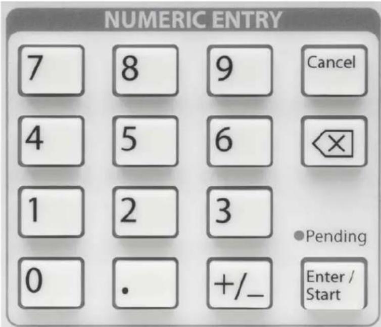
Whenenteringavoltagesettingthroughthenumerickeypad,the rangelimitsareimplicitlyenforcedduringentry.Thismeans,for example,thatwhenconfiguredforthe±10Vrange,thekeypadwill notallowyoutoenteramagnitudegreaterthan10.1atanytime.
With the first press of either a digit key ([0] through [9]), or the decimal point ([.]) or sign button ([+/-]), the display will switch into numericentrymode, withdigitsbeingaddedtothedisplayasthey arepressed. Tobackupasingledigit, usethe[ ]button.
Whileinnumericentrymode,the Pendingindicatorwillblink.This istoshowthenumericvaluehasnotyetbeensetintotheinstrument.
Pressingthe[Enter/Start]buttonwillacceptthecurrentlydisplayed value. Toleaveapendingnumericentrywithoutcausingthevalue tobeset,pressthe[Cancel]button.
2.1.5Sense
The[2or4Wire]buttonintheSENSEblockcontrolswhetherthe DC205useslocalorremotefeedbackforcontrollingthevoltageat theload.

Pressing[2or4Wire] togglesbetween2-wireand4-wire. This can be performed at any time, regardless of the state of the output.
2.1.6Config
The[Float/Ground]buttonintheCONFIGblockcontrolswhether theoutputvoltageLOterminaliselectricallyconnectedtochassis ground, orisolated.

Pressingthe[Float/Ground]button togglesbetweenGround(indicatingtheLOterminalistiedtochassisground),andFloating(indicatingtheoutputisisolatedfromchassisground.Thisoperation canbeperformedatanytime,regardlessofthestateoftheoutput.
2.1.7Scan
TheSCANblockofthefrontpanelistheentrypointforvoltage scanningfortheDC205.

Brieflypressingthe[SetupArm]buttonwillbringthescanparametersontothedisplay.Tonavigatebetweenparameters,usethe[◀] and[▶]selectbuttons.Pressing[Cancel]willexittheparameters mode.
Pressingandholdingthe[SetupArm]buttonformorethan2seconds willattempttoarmthescan.Inordertosuccessfullyarmascan,the outputmustalreadybeon,thebeginningandendingvoltagesofthe scanmustnotbeequaltoeachother,andtheinstrumentrangemust matchthescanrangepreviouslyselected.Oncearmed, theoutput voltageischangedtothebeginningscanvoltage,andtheArmed indicatorislit.
The Pending indicator is steady, likely, indicating the scan is ready and can be started by pressing the [Enter/Start] button. Pressing [Cancel] when as can is armed will "disarm" the scan, but the output voltage will remain at the value from the scan beginning. While a scan is running, pressing the [Cancel] button will halt the scan, and the output voltage will remain at the most recent output value from the scan.
Oncearmed, scanscanalsobestartedbyapplyingafallingedgeto the-TRIGInBNCconnectorontheDC205rearpanel, ortheremote *TRGcommand.
2.1.8Output
The[On/Off]buttonintheOUTPUTblockcontrolswhetherthevoltagesourcesisactive.
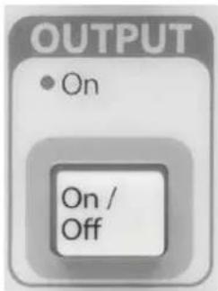
Pressing the [On/Off] button toggles between the On state and disabledstate.
Notethattheoutputcannotbeenabledwhentherangeis±100V unlesssthesafetyinterlockisclosed.
2.1.9Status
TheSTATUSblockofthefrontpanelhasthreeindicatorstohelp visualizetheconditionoftheDC205.
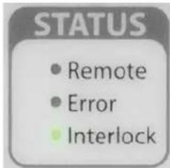
The Remote indicator illuminates whenever remote commands are received by the DC205 from any of the three remote interfaces. The indicator is not persistent—it will light briefly each time remote command character's received.
The Errorindicatorwillilluminatered, and the instrument beeps an audio alarm, whenever additional operation is attempted, or when an illegal remotecommand is received. This indicator is also not persistent, and will illuminate for approximately 1 second each time an error occurs.
The Interlock indicator will besteadily illuminated any time the safety interlock is closed.
2.1.10 SourceOut
TheSOURCEOUTblockofthefrontpanelcontainstheoutputterminalsforthevoltagesource.

Theredandblackterminalsattherightsideoftheblock,labelled OUTPUT,aretheHIandLOoutputterminalsofthesource.When theoutputisenabled,theprogrammedvoltageispresentbetween thesetwonodes,withtheredHIterminalatthegreaterpotential (whencommandedtopositiveoutput).
Theoutputiscurrentlimited,basedontherangeselection.Ifthe user'sloadbeginstodrawmorethanthecurrentlimit,theOverload indicatorwillilluminateredtoindicatetheinstrumentiscurrent limiting,andtheactualoutputvoltageisnotthecommandedvalue. CurrentlimitvaluesareshownintheOutputspecificationstable (pageviii).
When4-wiremodeisselectedforSENSE,theredandblackterminals undertheSENSElabelareusedforfour-wire(remote)sensingofthe outputvoltage.Whentheseinputterminalsareactive,theSENSE
indicatorjustabovetheterminalswillbeilluminated.
Notethatwhen4-wiremodeisselected,theSENSEterminalsare (weakly)connectedtotheoutputHIandLOterminalsthroughinternal0.5MΩresistors.
ThegreenterminalatthebottomoftheSOURCEOUTblockis chassisground.Nearthegreenterminal,twoindicatorsshow whetherthevoltagesourcesconfiguredasgroundedorisolated. Whengrounded,thelowergreenindicatorisilluminated,graphicallyshowingtheconnectionbetweentheblackLOterminaland chassisground.Whenisolated,theyellowFloatingindicatorislit, graphicallyshowingthatLOisdisconnectedfromchassis.
2.2 Scanning
Voltagescanningwasbrieflyintroducedinthepreviouschapter, undersection1.5.3. Scanningallowstheusertosetup andexecute linearsweepsoftheoutputvoltageoftheDC205.
2.2.1 Overview of scanning
Scansareimplementedbydividingthetimeintervalofascaninto smallsteps, of1 msduration, and commanding the voltage output in small incremental amplitude steps to simulate a smooth voltage slew. Note that, under careful examination, the stair-step nature of the voltagescansmaybeseen.
2.2.2 Scan terminology
When configuring a scan, the user selects a scan range, a beginning voltage, Vb , and an ending voltage, Ve , which command the starting and ending values. A scan duration time, Δt , is also selected in the range 100 ms to 9,999.9 s, as the time period to move from Vb to Ve . The effective voltages lewrate is given by (Ve - Vb)/Δt .
Scans can be configured as either unidirectional (starting at Vb ), or bidirectional(starting again at Vb and moving to Ve , then reversing backto Vb ). Scans can move towards increasing or decreasing output voltage, depending on the whether Ve is greater than or less than Vb . Notethatscanscannotbeexecuted if Vb = Ve .
Finally, scanscanbeconfigured asasingleshotorasindefinitely repeating.
The four permutations are shown in Figure 2.3. Not the scanduration time Δt is always the time to scan from Vb to Ve —for bidirectional scans, the overall repeating period is therefore 2 × Δt .

Figure2.3: The DC205 scan modes, shows schematically. Timeflow horizontally from left to right. All four examples are shown starting in the "Armed" state, with the scan beginning at the point marked "Triggered." Thescanduration is indicated near the bottom, and is common for all plots.
Onelastconfigurationchoiceiswhethertheinstrumentdisplaywill updateinnearrealtimeduringthescan,orstaticallydisplaythe wordontheonpanel.9
2.2.3Armingscans
Aascancanbe"armed"ifthefollowingconditionsaremet:
- Thescanrangematchestheinstrumentoutputrange
- The beginning and ending scan voltages are not equal
3.Theoutputison
If all three conditions are satisfied, then upon arming the scan, the DC205 output is set to the beginnings can voltage Vb , and the scan is said to be in the armed state.
Scanscanbearmedfromthefrontpanelbypassingandholdingthe [SetupArm]buttonforatleast2seconds,orbyissuingtheremote SCAAcommand(seesection4.4.6onpage4-13).
ThearmedstateisindicatedbytheArmedandPendingindicators bothbeingsteadilyilluminated.
2.2.4Triggeringscans
Whilearmed, ascancanbetriggered to start in one of three ways:
- Pressingthe[EnterStart]button
- Receiving afalling logiclevelonthe-TRIG In rear-panel BNC connector
- Withtheremote*TRGcommand
Oncetriggered, thecanisnowrunning and nolongerconsideredin the "armed" state. The Armed indicator goes off, and additional in-comingedges at the - TRIG In connector are ignored fortheduration of the scan.
2.2.5TRIGInandBUSYOut
Tworearpanelconnectorsprovideasimpleinterfacetotriggerand monitorscanswithexternalhardware.The-TRIGIninputisan active-low,TTL-compatibleinputthatcanbeusedtotriggerscans oncetheyarearmed.Thisnodehasa10kΩinternalpull-upresistor to+3.3V.Toexternallytriggerascan,theuserprovidesapulseto groundofatleast1μsdurationon-TRIGIn.Thescanistriggerdby thefallingedgeofthesignal.
Scansmaybemonitoredwiththe-BUSYOutoutput.Whenthe scan system is either idle or in the armed state, this output is at +3.3 V. While a scan is running, the -BUSY Out rear panel BNC signalisassertedlow(0V).-BUSYOutisdriventhrougha330Ω seriesimpedance.
It is possible to arrange several DC205s in a master-slave arrangement to synchronizescanning. Connectthe-BUSYOutsignalfromthe "master"DC205tothe"slave"unit(s)-TRIGInconnectors.Config-ureeachDC205forthedesiredscanparameters,andthenarmeach oftheunits. Tobeginthesynchronizedscan,triggerthescanfrom themasterunitusinganyofthe3methodslistedinsection2.2.4.As soonasthemasterunitistriggered,it's-BUSYOutsignalwillbe
assertedlow,whichinturnwillprovidethefallingedgetotheslave unit–TRIGInconnectors,triggeringtheirscansaswell.
Notethatthereisa±1mstimingapertureinthescanningsystem. Thismeanstherecanbeupto2msbetweenthestarttimeofanyofthesynchronizedscans.
2.2.6 Endingorcancellingscans
Single-shotscanswillendnaturallyaftertheprogrammedduration (either Δt , for unidirectional scans, or 2 × Δt , for bidirectional scans). Scansmayalsobehaltedasynchronouslyatanytimeafterstarting. For single-shot scans, this may be helpful especially for long Δt scans. Forrepeatingscans,thereisno"natural"endingtime,sothesemust alwaysbehaltedasynchronously.

Figure2.4:Exampleofarepeatingscan, haltedasynchronously.
Tohaltascanalreadyunderway,eitherpressthefront-panel[Cancel] button,orsendtheremotecommandSCAAIDLE(seesection4.4.6).
Whenascanisstoppedinthisway,theoutputvoltageisleftat themost-recentsettingofthescan,withtheoutputstillon.See Figure2.4.
2.3 Errormessages
The following messages may be displayed on the DC205 numeric display. This section provides a key to interpreting them messages.
2.3.1 Messagesatpoweron
When the DC205 successfully powererson, the display will show the firmware revision level, followed by the unit's serial number, and then begin normal operation. Anumber of internalself-checks are performed before beginning operation. If one of these fails, the following errormessages may appear on the numeric display.
2.3.1.1 Firmwarecorruption
If thenon-volatileprogrammemorybecomescorrupted, the DC205 may display themessage indicating the flashmemory is invalid. This failure is unlikely, but the instrument will not operate in this mode and must be returned to the factory for service.
2.3.1.2 Configurationlost
If the memory recording the last configuration of the DC205 is determined to be corrupted upon power-up, the message is displayed. This message may be cleared by pressing any button, after which the instrument will begin operating from the default configuration (although *RTShadrun).
Ifthestored "workingcalibration" valuesbecomescorrupted, the DC205themessage Err CL will bedisplayed. This message can be cleared by pressing any button, after which thenominalscale values will be overloaded. In this case, the instrument will operate but will not perform to specification.
Note that the working calibration is stored in a separate page of non-volatile memory from the original factory calibration. Acopy of the factory calibration values is stored in a separate page of the non-volatile memory. Depending on the how the working calibration became corrupted, it may be possible to recover proper operation by following the procedure for "Restore calibration" given above, in section 2.1.1.3(page2–4).
If the restore calibration procedure fails, then the unit should be returned to the factory for service.
2.3.2Fieldcalibration
Duringfieldcalibration(seechapter5),itispossibleforthegainor offsetadjustmenttoexceedthehardwarerangeoftheDC205.In thiscase,themessageisdisplayed,indicatingthe adjustmentswillbediscarded.
2.3.3 Scanning
Whenpreparinganoutputscanbyarmingthescan,severalconsistencychecksareperformed.Ifanyofthesefail,oneofthefollowing messageswillbedisplayed.
2.3.3.1 Scanrange
When the output ranged does not match the scan range, the message Err rAn GE is displayed.
2.3.3.2 Outputoff
If the output is off when attempting to arm as can, the message Err Out Off is displayed.
2.3.3.3 Beginning and ending voltages equal
If the beginning and ending voltages forthescan are not distinct, the message is displayed = E
2.3.4 Interlock
If the DC205 is operating on the ±100 V rangewith the output on, and
thesafetyinterlockopens,thenthemessage Err Intloc will be displayed. This message will persist until the user presses [Cancel]oranotherbutton,orsendsanyremotecommandingdata.
2.3.5 Unexpected resets
AnumberofinternalprotectionsmaycausetheDC205togenerate aninternalresetinresponsetoahardwarefailure.Ifthisoccurs,one ofthefollowingmessagesisdisplayedtoindicatethefailure.The messagewillpersistuntiltheuserpresses[Cancel],afterwhichthe instrumentwill(attemptto)resumenormaloperation.
If any of these are encountered unexpectedly, please contact the factory for possible service.
2.3.5.1 Undervoltage
I rESET indicatesthecpuundervoltagedetectorwasactivated.
2.3.5.2 Clockfailure
2 RESET indicatesthecpuoscillatorclockfailed.
2.3.5.3 Watchdog
3 rESET indicate the protective watchdog timer expired, which can be asymptomatic of a firmware failure.
2.3.5.4 Resetpinwakeup
4 rESET indicatesthehardwareresetnodegenerateda wakeup.
2.3.5.5 Otherwakeup
5 RESET indicatesawakeupfromasourceotherthanthe resetnode.
2.3.5.6 Hardware reset
6 RESET indicated the hardwareresetnodewasactivated.
2.3.5.7JTAG
7 rESET indicate the instrument was reset from the JTAG interface.
2.3.5.8 Firmware
B rESET indicatesafirmwarereset. Thisisnormaloperation followingasuccessfulfactory-calibrationrestoreoperation.
2.3.5.9Debug
9 rESET indicatesaresetgeneratedbythehostdebugging tool.
2.3.5.10EZport
10 RESET indicates a reset originating with the cpu's EZ-port.
2.3.5.11 Tamper
11 rESET indicatesthecputamperdetectionwastriggered.
2.3.5.12Unknown
12 RESET indicates a reset of unknown origin.
2.3.5.13Lockup
13 rE5E6 indicatesacpucorelockupfailure.
2.3.5.14 Peripheral failure
14 rE5Et indicatesacpuperipheralfailedtoacknowledge stopmode.
3Architecture
This chapter describes the architecture and theory of operation of the DC205 Precision DC Voltage Source.
InThisChapter
3.1Overview....3-2
3.2Voltagereference....3-3
3.3Digitaltoanalogconverter....3-3
3.4Amplifiers....3-4
3.4.1High-rangeamplifier....3-4
3.4.2Low-rangeamplifier....3-4
3.5Remotesensing ....3-4
3.1Overview
TheDC205isdesignedaroundthreecoreelementsthatcombineto delivertheinstrument'sperformance.Theseelementsare:
- Alow-noise, stable voltagereference
2.Ahigh-resolutiondigital-to-analogconverter
3.Asetoflow-noise,low-distortionamplifiers
AsimplifiedblockdiagramoftheDC205isshowninFigure3.1.
![graph TD A["±100V Power"] --> B["Interlock"] B --> C["100V Range"] C --> D["Range 2"] D --> E["500 kΩ On/Off"] E --> F["Output HI"] G["Voltage Reference"] --> H["High-Res DAC"] H --> I["10V Range"] I --> J["Range 0,1"] J --> K["Sense"] K --> L["500 kΩ"] L --> M["Sense LO"] N["Float"] --> O["R14 10 M…](/content/2026/06/1397139/images/5430b7d05bf666e885d0bb6b21840a71b13f13d7c33a927fb8affc736bf43de4.jpg)
Figure3.1:TheDC205blockdiagram.
3.2Voltagereference
Thelong-termstabilityandlow-frequencynoiseperformanceofthe DC205aredeterminedbythevoltagereference,whichprovidesa stablevoltageatthestartofthesignalchain.Anovenizedburied-zenerreferenceisusedintheDC205forthispurpose.Individual referencesaresubjectedtoanextendedburn-inandscreeningfor stability,temperaturecoefficient,andnoisepriortoinstallationin finalassemblies.
Thereferencehasawiderangeofoperatingvoltages,withapart topartvariationofover±3%.WhilethisismanyordersofmagnitudeworsethantheultimateaccuracyspecificationoftheDC205, the important aspect of the voltage reference is not its initial accuracy butratheritsstabilityovertime.TheaccuracyoftheDC205isestablished at factory calibration time by reference to a NIST-tracable high precision voltmeter.
Therawreferencevoltage(typically6.95V)isconvertedtobipolar referencevoltagesofapproximately±10.4VfortheDACstageusing low-offset chopper-stabilized op amps and temperature-tracking resistor networks.
Because the voltage reference isovenized to operate a stable, elevated temperature, some time is required following power-on before the ultimate performance of the DC205 is achieved. Themajority of the output voltage drift will occur during the first minute of operation; however, a full 2 hours must pass before the instrument will be at full specified performance.
3.3Digitaltoanalogconverter
The digital-to-analog converter (DAC) produces a programming voltage, proportional to the commanded output voltage, to send totheamplifierstage. TheDACisacompoundcircuitbasedon theAD579120-bit“R-2R”converter.Thisisextendedto21-bitoperationwiththeadditionofaleast-significantbitattheoutput of the AD5791. This ensures the least-significant hardware bit approximately corresponds to the least-significant count on the instrument's voltagesetting.
By using bipolar reference voltages, there is norelayswitching involved when the output passes through zero. In other words, 0V output corresponds approximately to mid-scale on the DAC output. This ensures that there are not transients or glitches when passing from negativetopositive, or positivetonegative, output voltages.
3.4Amplifiers
TwodistinctoutputamplifiersareincorporatedintheDC205toaccomodatethethreeoutputvoltageranges.
3.4.1 High-rangeamplifier
The highest output range, ±100V, hasaded output circuit powered by ±120V supply rails. This entiresubsystem, including the power to the high-range amplifier, is enabled only when the safety interlock is closed.
The high-range amplifier operates at a fixed gain of ×10 to allow the outputvoltagetoreach ±101V . The amplifier can produce output currents of 30mA, guaranteeing operation to ±25mA output.
3.4.2 Low-rangeamplifier
Thetwoloweroutputranges,±1V and ±10V, aresupplied by a single low-range amplifier. This amplifier operates independent of the state of the safety interlock, as it is powered by ±15 V supplies.
Thelow-rangeamplifieroperatesatoneoftwofixedgains,×1or ×1/10, corresponding to the ±10V range and ±1,V range, respectively.¹ Thisamplifierhasanapproximateoutputcurrentlimitof 70mA,guaranteeingoperationto±50mAoutputonboththe±1V and±10Vranges.
3.5 Remotesensing
TheDC205canoperateineither2-wire(localsensing)or4-wire (remotesensing)mode.Whenoperatingwithremotesensing,the userprovidesseparateconnections(Kelvinleads)fromtheDC205 totheuser'sload,andtheamplifierwillservotheoutputtoforce the measured voltage on the sense leads to equal the desired setting. Whileaddingsomecomplexityinwiring,operatingwithremote sensingcaneliminatetheerrorsduetoresistivevoltagedropwhen a user's load draws current from the DC205.
As indicated in the block diagram, there is input protection circuitry associated with the sense leads. A full understanding of these circuit features can help achieve best results with the DC205.
Thesenseamplifier itselfhasaveryhighinputimpedance(10 13 Ω). Ascanbeseenfromtheblockdiagram,however,thereare500kΩ connectionsbetweeneachsenselineandthecorrespondingoutput
line. TheseresistorsensurethatwhentheDC205isoperatingin4-wiremodebutthesenseleadsarenotconnected,thereremainssome localfeedbacktokeeptheoutputregulated.Additionally,there are twoantiparallelchainsofPNdiodesbetweenthesenseleadsand theircorrespondingoutputleads.Theseeffectivelyclampthesense leadstowithin±2.5Voftheoutputleads.Thisinturnimpliesthe largestohmicdropwhichcanbecorrectedwithremotesensingis about2.5V(perlead).
Asaresultofthediodestringsclampingthesense-to-outputvoltage at±2.5V,itispossibletoestimatethemaximumsenseleadresistance thatcanbeusedincaseswheretheuserloaddrawshighcurrent fromtheDC205.Atthemaximumoutputcurrent,thiscorresponds to a maximum lead resistance of about 50 Ω for the ±1 V and ±10 V ranges, and 100 Ω for the ±100 V range. Note that these limits are for themaximumoutputcurrent—iftheuserloaddrawssignificantly lesscurrent,thenhighersenseleadresistancecanbetoleratedwith-outtheclampdiodesgoingintoforwardconduction.Inthelimiting casewheretheloaddrawsnegligiblecurrent(veryhighimpedance),thereistypicallynobenefittooperatinginremotesensemode.
WARNING
Ascanbeseenfromtheblockdiagram,whenconfiguredfor4-wire operation,thesenseleadsareelectricallyconnectedtotheoutput nodesoftheDC205. Althoughoperationallythesenseleadsare inputstotheinstrument,usersshouldbeawarethattheSenseHI terminalwillalwaysbewithin±2.5 VoftheOutputHIpotential. Whenoperatingatthe±100 Vrange,usersmusttreatthesenseter- minalswiththesamecautionastheoutputterminals.
4RemoteOperation
This chapter describes operating the DC205 Precision DC Voltage Source over theremote interfaces.
InThisChapter
4.1Indexofcommands......4-2
4.2Alphabeticlistofcommands......4-4
4.3Introduction....4-6
4.3.1 Interfaceconfiguration....4-6
4.3.2 Isolation and computernoise......4-6
4.3.3Buffers....4-6
4.4Commands ....4-7
4.4.1 Commandsyntax......4-7
4.4.2Notation 4-8
4.4.3Examples....4-8
4.4.4Configurationcommands......4-9
4.4.5Settingcommands 4-10
4.4.6Scancommands....4-11
4.4.7 Setupcommands......4-14
4.4.8Interfacecommands ....4-14
4.4.9Statuscommands....4-18
4.5Statusmodel 4-22
4.5.1Statusbyte(SB)......4-23
4.5.2Servicerequestenable(SRE)......4-23
4.5.3 Standardeventstatus(ESR) .....4-24
4.5.4DCsourcestatus(DCCR/DCEV) .....4-24
4.1 Indexofcommands
| SymbolDefinition |
| f,gFloating-pointvalue |
| i,jUnsignedinteger |
| zLiteraltoken |
| (?)Requiredforqueries;illegalforsetcommands |
| varParameteralwaysrequired |
| {var}Requiredparameterforsetcommands;illegalforqueries |
| [var]Optionalparameterforbothsetandqueryforms |
| Configuration | ||
| RNGE(?){z}4-9Range | ||
| ISOL(?) {z} | 4 - 9 | Output isolation |
| SENS(?) {z} | 4 - 9 | Remote Sensing |
| SOUT(?) {z} | 4 - 9 | Output |
| Settings | |
| VOLT(?) {f} | 4 – 10 DC Voltage |
| Scanning | |
| SCAR(?) \ | 4 – 11 Scan Range |
| SCAB(?) \ | 4 – 11 Scan Beginning Voltage |
| SCAE(?) \ | 4 – 11 Scan Ending Voltage |
| SCAT(?) \ | 4 – 12 Scan Time |
| SCAS(?) \ | 4 – 12 Scan Shape |
| SCAC(?) \ | 4 – 12 Scan Cycle |
| SCAD(?) \ | 4 – 13 Scan Display |
| SCAA(?) \ | 4 – 13 Scan Arm |
| *TRG | 4 – 14 Remote Trigger |
| Setup | |
| KCLK(?) {z} | 4 - 14 Key Clicks |
| ALRM(?) {z} | 4 - 14 Audible Alarms |
| Interface | |
| *IDN? | 4-14 Identify |
| TOKN(?) {z} | 4 - 15 Token Mode |
| TERM(?) {z} | 4 - 15 Response Termination |
| *OPC(?) | 4-15 OperationComplete |
| COPC | 4-16 CancelPending*OPCFlag |
| BAUD(?) {z} | 4 - 16 Serial Baud Rate |
| *RST | 4-17 Reset |
Status
ILOC?4-18Interlock
OVLD?4-18Overload
*STB?[i]4-18Statusbyte
*SRE(?) [i,] {j} 4 - 18 Service request enable
*ESR?[i]4-18Standardeventstatus
*ESE(?) [i,] {j} 4-19 Standard event status enable
*CLS4-19ClearStatus
LEXE?4-19LastExecutionError
LCME?4-20Lastcommanderror
DCCR?[i] 4-20DCSourceCondition
DCPT(?) [i,] {j} 4-20 DC Source Positive-Transition
DCNT(?) [i,] {j} 4 - 20 DC Source Negative-Transition
DCEV?[i] 4-21DCSourceEvent
DCEN(?) [i,] {j} 4-21 DC Source Event Enable
4.2Alphabeticlistofcommands
★
*CLS4-19ClearStatus
*ESE(?) [i,] {j} 4-19 Standard event status enable
*ESR?[i]4-18Standardeventstatus
*IDN?4-14Identify
*OPC(?)4-15OperationComplete
*RST4-17Reset
*SRE(?) [i,] {j} 4-18 Service request enable
*STB?[i]4-18Statusbyte
*TRG4-14RemoteTrigger
A
ALRM(?) {z} 4-14 Audible Alarms
B
BAUD(?) {z} 4-16 Serial Baud Rate
C
COPC 4-16CancelPending*OPCFlag
D
DCCR?[i] 4-20DCSourceCondition
DCEN(?) [i,] {j} 4-21 DC Source Event Enable
DCEV?[i] 4-21DCSourceEvent
DCNT(?) [i,] {j} 4 - 20 DC Source Negative-Transition
DCPT(?) [i,] {j} 4-20 DC Source Positive-Transition
|
ILOC? 4-18Interlock
ISOL(?) {z} 4-9 Output isolation
K
KCLK(?) {z} 4-14 Key Clicks
L
LCME? 4-20Lastcommanderror
LEXE? 4-19LastExecutionError
0
OVLD? 4-18Overload
R
RNGE(?){z}4–9Range
s
SCAA(?){z}4-13ScanArm
SCAB(?){f}4-11ScanBeginningVoltage
SCAC(?){z}4-12ScanCycle
SCAD(?){z}4-13ScanDisplay
SCAE(?){f}4-11ScanEndingVoltage
SCAR(?){z}4-11ScanRange
SCAS(?){z}4-12ScanShape
SCAT(?){f}4-12ScanTime
SENS(?){z}4-9RemoteSensing
SOUT(?){z}4-9Output
T
TERM(?) {z} 4-15 Response Termination
TOKN(?){z}4-15TokenMode
V
VOLT(?) {f} 4-10 DC Voltage
4.3 Introduction
RemoteoperationoftheDC205istroughasimplecommandlanguagedocumentedinthischapter.Bothsetandqueryformsofmost commandsaresupported,allowingtheusercompletecontrolofthe voltagesourcefromaremotecomputerthroughUSBorRS-232,or throughtheopticalfiberandtheSX199interfacetoGPIB,RS-232,or ethernetinterfaces.
Whereapplicable, the corresponding front-panel interface to each command is also indicated. Most instrument settings are retained in non-volatile memory. Upon power-on, these settings are restored to their values before the power was turned off. Where appropriate, the default value for parameters is listed in boldface in the command descriptions.
4.3.1 Interfaceconfiguration
TheUSBinterfaceisimplementedasaserialportemulator,with fixedbaudrateof115,200.Theopticalfiberinterfaceisfixedat9600 baudforoperationwiththeSX199interfaceunit.TheRS-232DB-9 interface is configured by default as 9600 baud, 8-bit, no parity or flow control. TheRS-232interfacecanbecommandedtodifferentbaud ratesunderprogramcontrolwiththeBAUDcommand,orthrough thepower-onconfigurationmethoddescribedinsection2.1.1.4on page2–4.
4.3.2 Isolation and computernoise
WhenevertheDC205isdirectlyconnectedtoacomputerthrough theRS-232orUSBinterface,thereisthepotentialforhighfrequency (RF)noisetobeinjectedintotheanalogcircuitryoftheinstrument. Toavoidthiswhenremotecommandingisrequired,usetheoptical fiberinterfacetogetherwiththeSX199interfaceunit.
4.3.3Buffers
TheDC205storesincomingbytesfromtheremoteinterfacesinseparate 128-byte input buffers. Characters accumulate in the input buffer until a command terminator ( CR or LF ) is received, at which point themessageis parsedandenqueuedforexecution. Thecommand queuecanholdupto20remotecommands.Queryresponsesfrom theDC205arebufferedininterface-specific256-byteoutputqueues.Queriesarereturnedtotheinterfacefromwhichtheywerereceived(RS-232,USB,oroptical).
If an input buffer overflows, then all data in the input buffer are discarded, and the DDEbitis recorded in the ESRstatusregister.
4.4 Commands
Thissectionprovidessyntaxanddescriptionsforremotecommands.
4.4.1 Commandsyntax
The four letter mnemonic (shown in CAPS) in each command sequence specifiesthe command. The command mnemonic is optionally followed by one or more parameters.
Commandsmaytakeeithersetorqueryform,dependingonwhether the“?”characterfollowsthemnemonic.Setonlycommandsare listed without the “?”, query only commands show the “?” after the mnemonic,andoptionallyquerycommandsaremarkedwitha“(?)”.
Parametersshownin{}and[]arenotalwaysrequired.Parameters in{}arerequiredtosetavalue,andshouldbeomittedforqueries.Parametersin[]areoptionalinbothsetandquerycommands.Parameterslistedwithoutsurroundingcharactersarealwaysrequired.
Donotsend()or{}or[]aspartofthecommand.
Multipleparametersareseparatedbycommas.Multiplecommands maybesentononecommandlinebyseparatingthemwithsemicolons(;)solongastheinputbufferdoesnotoverflow.Commands are terminated by either CR or LF characters. Null commands andwhitespacesareignored.Executionofthecommanddoesnot beginuntilthecommandterminatorisreceived.
tokens Token parameters (generically shown as z in the command descriptions) can be specified either as a key word or an integer value. Command descriptions list the valid keyword options, with each keyword followed by its corresponding integer value. Forexample, to set the remote sensing mode to 4-wire, the following two commands are equivalent:
SENS FOURWIRE —or— SENS 1
Forqueriesthatreturntokenvalues,thereturnformat(keywordor integer)isspecifiedwiththeTOKNcommand.
4.4.2 Notation
The following tablegivesthenotationusedinthecommanddescriptions:
SymbolDefinition
fFloating-pointvalue
i,jUnsignedinteger
zLiteraltoken
(?)Requiredforqueries;illegalforsetcommands
varParameteralwaysrequired
{var}Requiredparameterforsetcommands;illegalforqueries
[var]Optionalparameterforbothsetandqueryforms
4.4.3Examples
Each command is provided with a simple example illustrating its usage. In these examples, all datasent by the host computer to the DC205 are set as straight teletype font, while responses received by the host computer from the DC205 aresetasslanted teletype font.
The usage examples vary with respect to query, optional parameters, and token formats. They are not exhaustive, and are intended to provide a convenient starting point for user programming.
4.4.4 Configuration commands
| RangeRNGE(?){z} | |
| Set(query)thevoltagerange{to z=(RANGE1 0, RANGE10 1, RANGE100 2)}. | |
| TheRNGEcommandisequivalenttopressingthe[Range]button.RNGEsetstheoutputrangeoftheDC205tooneofthethreerangesettings: ±1 V, ±10 V, or ±100 V. | |
| Notethatateachrange,thesourcecanbesetto±101%ofthenominalfullscale. | |
| TheRNGEcommandmaynotbesetwhiletheoutputisenabled. | |
| RNGE?Example: | |
| RANGE1 | |
| Outputisolation|SOL(?){z} | |
| Set(query)theoutputisolationconfiguration{to z=(GROUND 0, FLOAT 1)}. | |
| The|SOLcommandisequivalenttopressingthe[Float/Ground]button.Thiscommandmaybesentatanytime. | |
| ISOL1Example: | |
| SENS(?) {z} | Remote Sensing |
| Set(query)theremotesensingmode{to z=(TWOWIRE 0, FOURWIRE 1)}. | |
| The SENS command is equivalent to pressing the [2 or 4 Wire] button.Thiscommandmaybesentatanytime. | |
| Example: | SENSFOURWIRE |
| SOUT(?){z} | Output |
| Set (query) the voltage source output mode {to z=(OFF 0, ON 1)}. | |
| The voltage source output is enabled or disabled using the SOUTcommand. When set to SOUT OFF, the OUTPUT HI terminal isdisconnectedfromtheoutputcircuitry. Ifthesourceisconfiguredfor|SOLGROUND,thentheOUTPUTLOterminalremainsconnectedtochassisground. | |
| If the source range is set to RANG RANGE1 or RANG RANGE10, thenSOUT ON may be sent at any time. However, if the source range is set |
to RANG RANGE100, then SOUT ON may only be sent while the safety interlockisclosed.
The SOUT command is equivalent to pressing the OUTPUT [On/Off] button.
SOUT?Example:
0
4.4.5 Setting commands
DCVoltageVOLT(?){f}
Set (query) the commanded source voltage {to f}, in volts. The default value is VOLT0.0.
Note that the allowable range for VOLT depends on the RNGE setting:
RangeMinimumMaximum
±1V-1.010000+1.010000
±10V | -10.10000+10.10000
±100V-101.0000+101.0000
TheVOLTcommandmaybequeriedatanytime,andsetanytime except when a scan is either armed or running. Queries of VOLT? while a scan is running will reply with the approximate realtime outputvoltage,updatedapproximatelyevery150ms.
Note also that VOLT? queries always respond with the voltage setting of the instrument—no actual measurement of output voltage is ever performed by the DC205.
TheVOLTcommandisequivalenttothefrontpanelnumericentrykeypad.
Example: VOLT 1.25e-3; VOLT?
0.001250
4.4.6 Scancommands
| TheDC205canperformlinearvoltagescans,eitherasasingle-shot orindefinitelyrepeatingpattern.Thefollowingcommandsprovide theremoteinterfacetothiscapability. | |
| ScanRangeSCAR(?){z}Set (query) the scan range {to z=(RANGE1 0, RANGE10 1, RANGE100 2)}.Scanningmustbeconfiguredforaspecificoutputrange,whichcan besetindependentofthepresentvalueoftheactiveoutputrange (seeRNGE).Atthetimeascanisarmed,thescanrangeSCARmust matchtheoutputrangeRNGE.When SCAR is modified, then both SCAB and SCAE (the beginning andendingvoltagesforthescan)areresetto0V.SCARcannotbesetwhenascaniseitherarmedorrunning.TheSCARcommandisequivalenttotheentryfieldunder SCANSetup. | |
| Example: | SCARRANGE10 |
| SCAB(?) {f} | Scan Beginning VoltageSet (query) the scan beginning voltage {to f}, in volts. The default valueisSCAB0.0.ThevalueforSCABmustbewithinthevalidrangefortheselected scan range, SCAR. Limits are the same as for the VOLT command.SCABcannotbesetwhenascaniseitherarmedorrunning.TheSCABcommandisequivalenttothe entryfieldunderSCAN Setup. |
| Example: | SCAB0.125 |
| SCAE(?) {f} | Scan Ending VoltageSet (query) the scan ending {to f}, in volts. The default value is SCAE1.0.ThevalueforSCAEmustbewithinthevalidrangefortheselected scan range, SCAR. Limits are the same as for the VOLT command.SCAE cannotbesetwhenascaniseitherarmedorrunning.TheSCAEcommandisequivalenttothe entryfieldunderSCAN Setup.ScanTimeSCAT(?){f} |
| Set (query) the scan duration {to f}, in seconds. The default value is SCAT1.0. | |
| The value for SCAT must be between 0.1 and 9999.9. Values are roundedtothenearest0.1s. | |
| ThedurationtimesetbySCATisdefinedasthetimetoscanfrom thebeginningvoltagetotheendingvoltage;ifthescanshapeis up-down,thenthetotalscanperiodwillbetwicethevalueofSCAT. | |
| SCATcannotbesetwhenascaniseitherarmedorrunning. | |
| TheSCATcommandisequivalenttotheentryfieldunderSCAN Setup. | |
| Example: | SCAT3600 |
| SCAS(?) {z} | Scan Shape |
| Set (query) the scan shape {to z=(ONEDIR 0, UPDN 1)}. | |
| Scans can be configured to either slew in one direction only, from SCAB to SCAE (SCAS ONEDIR), or they can operate as a “round trip” from SCAB to SCAE, and then back to SCAB (SCAS UPDN). | |
| Notethatforeithershape,thereisnorestrictiononthetherelation betweenSCABandSCAE-theactualscancanbeginwithvoltage eitherincreasingordecreasing. | |
| SCAScannotbesetwhenascaniseitherarmedorrunning. | |
| The SCAS command is equivalent to the 5h entry field under SCANsetup. | |
| Example: | SCAS? |
| ONEDIR | |
| SCAC(?) {z} | Scan Cycle |
| Set (query) the scan cycling mode {to z=(ONCE 0, REPEAT 1)}. | |
| Scanscanbeconfiguredtoeitherexecuteasingletime(SCACONCE), ortorepeatindefinitely(SCACREPEAT). | |
| When SCAC REPEAT is set, and the scan shape SCAS ONEDIR is selected,thentheoutputvoltagewillchangeabruptly,fromSCAETO SCAB,attheconclusionofeachcycle. | |
| When SCAC ONCE is set, the output voltage remains at SCAE at the conclusionofthescan.ItispossibletosetSCACwhileascanisinprogress.Inthisway, itispossible,forexample,toendarepeatingscanatthenextnatural ending point (either SCAE, if the SCAS=ONEDIR, or SCAB, if SCAS=UPDN).TheSCACcommandisequivalenttotheentryfieldunderSCANsetup.SCAC0Example: | |
| ScanDisplaySCAD(?){z}Set (query) the scan display mode {to z=(OFF 0, ON 1)}.Whenascanisinprogress,thedisplaywilleithershowa(near)real timeupdateoftheoutputvoltage,oritwillremainstatic,displayingScadnnin9.TheSCADcommandisequivalenttotheentryfieldunderSCANsetup. | |
| SCAA(?) {z} | Scan ArmSet the scan armed mode {to z=(IDLE 0, ARMED 1)}, or query the scan armed mode as z=(IDLE 0, ARMED 1, or SCANNING 2).Setting SCAA ARMED will arm the scan. In order to successfully arm thescan, theDC205mustalreadyhavetheoutputenabled. Also, thepresentrangesetting(RNGE)mustmatchtheprogrammedscan range(SCAR),andthebeginningandendingvoltagesofthescan (SCABandSCAE)mustnotbeequal.Thisisequivalenttopressing andholdingthe[SetupArm]button.Sending the SCAA IDLE command will disarm an already-armed scan.SCAAIDLEwillalsocancelascanthatiscurrentlyinprogress (that is, in the SCAA SCANNING state). This is equivalent to pressing the[Cancel]buttonwhenarmedorscanning.NotethathequerySCAA?canreturnthevalueSCANNING(ornumerical value 2, but this value is illegal for the set version of the command. To begin a scan after arming, use the *TRG command (seebelow).When armed, the scan can be started by either pressing [Enter/Start], sending the remote *TRG command, or by a falling logic edge on the rearpanel–TRIGInBNCconnector. |
| Example: | SCAAARMEDRemoteTrigger*TRGRemotelystartascan.Notethatthescanmustalreadybearmedfor*TRGtostartascan.The*TRGcommandisequivalenttothe[Enter/Start]buttonwhen thescansystemisArmed. |
| 4.4.7Setupcommands | |
| ClicksKCLK(?){z}Set (query) audible key clicks {to z=(OFF 0, ON 1)}.Keyclickmodecanalsobechangedthroughapower-onkeypress(seesection2.1.1.5onpage2-4). | |
| AudibleAlarmsALRM(?){z}Set (query) audible alarms {to z=(OFF 0, ON 1)}.Notethatallsoundsthatarenot"keyclicks"areconsidered"alarms"forthepurposeoftheALRMcommand.Alarmmodecanalsobechangedthroughapower-onkeypress(seesection2.1.1.6onpage2-4). | |
4.4.8 Interface commands
| *IDN? | Identify |
| QuerytheDC205identificationstring. | |
| Theresponseisformattedas:StanfordResearchSystems, DC205, s/n*********, ver#.##where ***** is the 8-digit serial number, and #.## is the firmware revisionlevel. | |
| Example: | *IDN?StanfordResearchSystems, DC205, s/n20512345, ver1.00TokenModeTOKN(?){z}Set (query) the token response mode {to z=(OFF 0, ON 1)}.Tokenresponsemodecontrolstheformattingofresponsemessages generatedbytheDC205toremotequeriesoftoken-typevalues.When TOKN OFF, the DC205 responds with the numeric version of the token quantity. When TOKN ON, the text version is returned.TOKN?Example:ON |
| ResponseTerminationTERM(?){z}Set (query) the token response mode {to z=(NONE 0, CR 1, LF 2, CRLF3,LFCR4)}.ResponsemessagesgeneratedbytheDC205willbeterminedby the0-,1-or2-characterterminationsequencespecifiedbyTERM.NotethatheTERMcommandisinterfacespecific.Inotherwords,if TERM LF is received on the RS-232 interface, and then TERM CRLF isreceivedontheUSBinterface,thenqueriesreceivedontheRS-232 interface shall generate response messages terminated with the LF character, while queries received on the ethernet interface shall generate response messages terminated by the CR and LF characters.TERMsettingsnotaresavedwhentheDC205ispoweredoff.They arenotaffectedby*RST. | |
| Example: | TERMLF |
| *OPC(?) | OperationCompleteThe set form, *OPC, will set the OPC bit in the Standard Event Status register; the query form, *OPC?, will return the value 1.The*OPC?querywillnotbeprocessedbythecommandexecution of the DC205 until all preceding commands have been executed and completed, and the *OPC command will not set the OPC bit until all preceding commandshavebeenexecuted.*OPC? can be helpful in combination with scans. If a scan is running (SCAA SCANNING state), then a *OPC? will block all 1 further commandsfrom executingontheDC205 untilthescancompletes, atwhichtimeitwillrespondwiththe1queryresponse.Ifthescan is running while SCAC REPEAT, then a *OPC? query will never return and will leave the remote interface blocked, until the front panel |
1 except for the COPC command
| [Cancel]buttonispressed(haltingthescan).*OPC?queriescanbe cancelledwiththespecialCOPCcommand.Thesetversionofthecommand,*OPC,doesnotblocktheremote commandinterface—subsequentcommandswillcontinuetobeprocessedpromptly.*RST;SCAT10;SOUT1;SCAA1;*TRG;*OPC?Example:1ThisexampleresetstheDC205,thenprogramsthescantimeΔtto 10s,turnstheoutputon,armsthescan,andthentriggersthescan. Thefinal*OPC?queryrequeststheDC205toreply1whentescan isfinished.Thefinalresponse(1)doesnotappearuntilthescanis finished,10safterthescanstarts. | |
| CancelPending*OPCFlagCOPCThisset-onlycommandwillimmediatelycleartheoperationpending stateoftheDC205,effectivelycancelingacurrentlypending*OPC? query.TheCOPCcommandistreatedspeciallybytheDC205remotecom-mand parser, allowing it to be executed ahead of commands that werereceivedaheadofitbutnotyetexecuted.Thisprivilegedstatus isnecessarytocancela*OPC?query,sinceallothercommandsare blockedbythe*OPC?whileitispending. | |
| Example: | SCACREPEAT;SCAAARMED;*TRG;*OPC?Atthispoint,theremoteinterfaceisblocked.Becausethescanwas triggeredwhenarmedtorepeatindefinitely,the*OPC?willnever return.Theremoteinterfacecanbeclearedfornewcommandswith thefollowing: |
| Example: | COPC1Notethe1appearsfromtheprevious*OPC?query,astheDC205 isforcedbyCOPCtobehaveasthoughtthependingcommandis completed. |
| BAUD(?) {z} | Serial Baud RateSet (query) the RS-232 baud rate {to z=(BD9600 0, BD19200 1, BD38400 2, BD57600 3, BD115200 4)}.SetstheRS-232(DB-9connector)baudratetooneofthefiveallowed rates. NotethatneithertheUSB,northeopticalfiber,interfacesare modifiedbytheBAUDcommand. |
NotealsothatBAUDsettingsarenon-volatile, andareretained throughpowercycles.
ChangestotheRS-232baudratetakeplaceimmediately;once changed,theuser'scommunicationsoftwareshouldbealsochange baudratetomaintaincommunications.
Baudratemayalsobechangedthroughapower-onkeypress(see section2.1.1.4onpage2–4).
BAUD4Example:
Reset*RST
ResettheDC205toitsdefaultconfiguration.
The following commands are internally executed upon receipt of the *RST command:
•RNGERANGE1
•ISOLGROUND
•SENSTWOWIRE
•SOUTOFF
•VOLT0.0
•SCARRANGE1
•SCAB0.0
•SCAE1.0
•SCAT1.0
•SCASONEDIR
•SCACONCE
•SCADON
•SCAAIDLE
•KCLKON
•ALRMON
NotethattheRS-232baudrateisunaffectedby*RST.
Thesamedefaultconfigurationcanbesetbyperformingapower-on resetoftheDC205(seesection2.1.1.1onpage2-3).Note,however, that the front-panel power-on reset will also reset the RS-232 baud rateto9600.
4.4.9Statuscommands
| Interlock|LOC?Query the interlock condition as z=(OPEN 0, or CLOSED 1).Readsthecurrentvalueoftheinterlock.Ifthesafetyinterlockis closed, |LOC? returns CLOSED 1; otherwise it returns OPEN 0.Notethe|LOC?querycorrespondstotheInterlockbitintheDCCR conditionregister.ILOC?Example:CLOSED | ||
| OverloadOVLD?Query the overload condition as z=(OKAY 0, or OVLD 1).Readsthecurrentvalueofthesignaloverloadstatus.ReturnsOVLD1 iftheoutputisoverloaded(currentlimitmode),orOKAY0otherwise.NotetheOVLD?querycorrespondstotheOVLDbitintheDCCR conditionregister.0VLD?Example:0 | ||
| *STB?[i] | StatusbyteReadstheStatusByteregister[biti].*STB?Example:0 | |
| *SRE(?) [i,] {j} | Service request enableSet (query) the Service Request Enable register [bit i] {to j}. | |
| Example: | *SRE0,1 | |
| *ESR?[i] | StandardeventstatusReadstheStandardEventStatusRegister[biti].Uponexecuting*ESR?, thereturnedbit(s)oftheESRregisterare cleared.*ESR?Example:64 | |
| *ESE(?) [i,] {j} | Standard event status enableSet (query) the Standard Event Status Enable Register [bit i] {to j}.*ESE6, 1Example:ESE?64 | |
| ClearStatus*CLS*CLSimmediatelyclearsalloftheeventstatusregisters.*CLSExample: | ||
| LastExecutionErrorLEXE?Querythelastexecutionerrorcode.AqueryofLEXE?alwaysclearstheerrorcode,soasubsequentLEXE?willreturn0. Validcodesare: | ||
| Value | Definition | |
| 0 | NoexecutionerrorsincelastLEXE? | |
| 1 | Illegalvalue | |
| 2 | Wrongtoken | |
| 3 | Invalidbit | |
| 4 | Queuefull | |
| 5 | Notcompatible | |
| Example: | RNGEO;VOLT3.1;LEXE?;LEXE?1;0The error (1, “Illegal value,”) is because the parameter value (3.1) is too large for VOLT on the ±1 V range. The second read of LEXE? returns0. | |
| LastcommanderrorLCME?Querythelastcommanderrorcode.AqueryofLCME?alwaysclearstheerrorcode,soasubsequentLCME?willreturn0. Validcodesare:ValueDefinition | ||
| 0NoexecutionerrorsincelastLCME?1Illegalcommand2Undefinedcommand3Illegalquery4Illegalset5Missingparameter(s)6Extraparameter(s)7Nullparameter(s)8Parameterbufferoverflow9Badfloating-point10Badinteger11Badintegertoken12Badtokenvalue13Badhexblock14Unknowntoken*IDNExample:LCME?4Theerror(4,"Illegalset")isduetothemissing"?". | ||
| DCSourceConditionDCCR?[i]ReadtheDCSourceConditionRegister[bit]. | ||
| DCPT(?) [i,] {j} | DC Source Positive-TransitionSet (query) the DC Source Positive Transition Register [bit i] {to j}.DCPT1, 1Example: | |
| DCNT(?) [i,] {j} | DC Source Negative-TransitionSet (query) the DC Source Negative Transition Register [bit i] {to j}.Example: DCNT?2DCSourceEventDCEV?[i]QuerytheDCSourceEventRegister[biti].UponexecutinganDCEV?query,thereturnedbit(s)oftheDCEVregisterarecleared.DCEV?Example:2 | |
| DCEN(?) [i,] {j} | DC Source Event EnableSet (query) the DC Source Status Enable Register [bit i] {to j}.DCEN1, 1Example: | |
4.5Statusmodel
TheDC205statusregistersfollowthehierarchicalIEEE-488.2format.statusregisters AblockdiagramofthestatusregisterarrayisgiveninFigure4.1.
![graph TD A["Standard Event Status"] --> B["ESR ESE"] B --> C["UNDEF"] B --> D["URQ: User Request"] B --> E["CME: Command Error"] B --> F["EXE: Execution Error"] B --> G["DDE: Device Error"] B --> H["QYE: Query Error"] B --> I["UNDEF"] B --> J["OPC: Operation Complete"] K["DC Source Status"] --> L["E…](/content/2026/06/1397139/images/fa51aa1060d966a38c17c181cc4076cf05e77d31227c9769cb525dc666352d61.jpg)
Figure4.1:StatusModelfortheDC205PrecisionDCVoltageSource
Therearefivecategoriesofregistersinthestatusmodelofthevoltage source:
Condition Registers: These read-only registers correspond to the real-time condition of some underlying physical property being monitored. Queries return the latest value of the property, and have no further side effects. Condition register names end with CR.
Transition Selection Registers : These read/write registers define specific transition events (0 → 1or1→0). The eventisthendefinedbytheselectedtransition in the value of the underlying condition register. Transition registernamesendwithPTorNT.
EventRegisters: Theseread-onlyregistersrecordtheoccurrenceofdefined eventswithinthevoltagesource. Iftheeventoccurs, thecorresponding bit is set to 1. Upon querying an event register, any set bits within it are cleared. These are sometimes known as
"stickybits,"sinceonceset,abitcanonlybeclearedbyreading itsvalue.EventregisternamesendwithSRorEV.
EnableRegisters: Theseread/writeregistersdefineabitwisemaskfortheircorrespondingeventregister.Ifanybitpositionissetinanevent registerwhilethesamebitpositionisalsosetintheenable register,thenthecorrespondingsummarybitmessageissetin theStatusByte.EnableregisternamesendwithSEorEN.
StatusByte: Thisread-onlyregisterrepresentsthetopofthestatusmodel, andispopulatedwithsummarybitmessagesandinterface conditionbits.EnabledbitswithintheStatusBytegeneratethe MasterSummaryStatusbitwithintheStatusByteregister.
Atpower-on, allstatusregistersarecleared.
4.5.1Statusbyte(SB)
TheStatusByteisthetop-levelsummaryoftheDC205statusmodel. WhenenabledbytheServiceRequestEnableregister,abitsetintheStatusBytecausesheMSS(MasterSummaryStatus)bittobeset.
| WeightBitFlag |
| 10DCSB |
| 21undef(0) |
| 42undef(0) |
| 83undef(0) |
| 164undef(0) |
| 325ESB |
| 646MSS |
| 1287undef(0) |
DCSB:DCSourceStatusBit. Indicateswhetheroneormoreofthe enabledeventsintheDCSourceEventStatusRegisteristrue.
ESB:EventStatusBit.Indicateswhetheroneormoreoftheenabled eventsintheStandardEventStatusRegisteristrue.
MSS:MasterSummaryStatus.Indicateswhetheroneormoreofthe enabledstatusmessagesintheStatusByteregisteristrue.
Thisregisterisreadwiththe*STB?query.
4.5.2 Servicerequestenable(SRE)
EachbitintheSREcorrespondsone-to-onewithabitintheSBregister,andactsasabitwiseANDoftheSBflagstogenerateMSS.Bit6of theSREisundefined—settingithasnoeffect,andreadingitalways returns 0. This register is set and queried with the *SRE(?) command.
Atpower-on, thisregisteriscleared.
4.5.3 Standardeventstatus(ESR)
TheStandardEventStatusRegisterconsistsof8eventflags. These eventflagsareall"stickybits"thataretbythecorresponding events, andclearedonlybyreadingorwiththe*CLScommand. Reading a single bit (with the *ESR? i query) clears only Bit i.
| WeightBitFlag |
| 10OPC |
| 21undef(0) |
| 42QYE |
| 83DDE |
| 164EXE |
| 325CME |
| 646URQ |
| 1287undef(0) |
OPC:OperationComplete.Setbythe*OPCcommand.
QYE:QueryError.Indicatesdataintheoutputqueuehasbeenlost.
DDE:Device-DependentError.Indicatesaninputbufferorinternal commandqueueoverflow.
EXE:ExecutionError. Indicate the error in a command that was successfully parsed. Out-of-range parameters are an example.
CME:CommandError.Indicatesacommandparser-detectederror.
URQ:UserRequest.Indicatesthatafront-panelbuttonwaspressed.
4.5.3.1 Standardeventstatusenable(ESE)
TheESEactsasabitwiseANDwiththeESRregistertoproducethe single-bitESBmessageintheStatusByteRegister(SB).Theregister canbesetandqueriedwiththe*ESE(?)command.
Atpower-on, thisregisteriscleared.
4.5.4DCsourcestatus(DCCR/DCEV)
The DC source status is monitored by a real-time condition register (DCCR), a pair of transition selection registers, and the latching event register.
4.5.4.1 DCsourcecondition(DCCR)
TheDCSourceConditionRegisterconsistsof2conditionflagsthat reflectthereal-timeconditionoftheDC205.ReadingtheDCCRhasnoeffectonanyvalues.
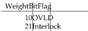
OVLD:SetwhentheDCoutputisoverloaded(currentlimiting).
Interlock:Setwhenthesafetyinterlockisclosed(±100Vrangeispermittedforoperation).
4.5.4.2DCsourcepositive/negativetransition(DCPT/DCNT)
Thesetwo8-bitwideregisterscontrolthemappingoftransitionsin theDCCRtosettingflagsintheDCEVregister.Foranyparticular event,ifthecorrespondingbitissetinDCPT,thena0→1transition intheDCCRcausesthebittobesetintheDCEV.Likewise,ifabitis setinDCNT,thena1→0transitionintheDCCRcausesthebittobe setintheDCEV.
Allcombinations of DCPT and DCNT settings are valid. At power-on, both DCPT and DCNT are cleared.
4.5.4.3DCsourceevent(DCEV)
This8-bitwideregistermonitorsselecteddeventsintheDCCR, based ontransitionsselectedinDCPTandDCNT. Whentheselectedtransition(s) occur, the corresponding bitset. Reading theregisterclear it (readingasinglebitclearsonlythatbit). Thisregisteriscleared by the*CLScommand.
InadditiontomonitoredeventsfromtheDCCR,twodiscreteevents aredirectlydefinedinDCEVwithoutcorrespondingreal-timeconditionbitsintheDCCR.Theseare:
| WeightBitFlag |
| 1287ScanCancelled |
| 646ScanCompleted |
ScanCancelled: Indicate that as can wasterminated prior to completion.
ScanCompleted: Indicate that as can be ended normally, at the completion of the programmed cycle.
4.5.4.4DCsourcestatusenable(DCSE)
Thisisan8-bitwideregisterthatmaskstheDCEVregister.The logicalORofthebitwiseANDofDCEVandDCENproducesthe DCSBmessageintheStatusByteregister(SB).
5FieldCalibration
ThischapterprovidesinstructiosforcalibratingtheDC205Precision DCVoltageSourceinthefield.
InThisChapter
5.1 Introduction to field calibration.....5-2
5.2 Calibrationmethod....5-2
5.3 Equipmentneeded....5-3
5.4Detailedprocedure....5-3
5.5 Followingfieldcalibration....5-5
5.6Restoringthefactorycalibration....5-6
5.1 Introductiontofieldcalibration
The DC205 provides outstanding stability and accuracy for extended period soft time. The factory calibration procedures set gain and offset coefficients, as well as small non-linear corrections, for all three operating ranges.
Astheinstrumentages, slow changes in the voltage reference, amplifier gains, and offset voltage can occur, which is in part there reason for accuracy specifications given for 90-day and 1-year periods (see page viii). However, the small nonlinear artifact that are corrected by the factory calibration are expected to be relatively stable, compared with the voltage reference and gain-setting resistive elements.
Asaresult, itistypicallypossibletorestoretheDC205toits24-hour accuracy level by applying amorelimited calibration procedure, correcting gain and offset but leaving the small non-linear corrections unchanged from their factory settings.
This chapter describes the process for performing that limited calibration. Not that it is always possible to restore the entire factory calibration by following the procedure described in Section 2.1.1.3 (page 2–4).
5.2 Calibrationmethod
FieldcalibrationoftheDC205isperformedbyplacingtheinstrument intoaspecialcalibrationmodeduringstart-up.Byusingahighperfomancedcvoltagemeasuringinstrument,theoperatorwillcorrect theDC205'soutputtobecometheexactvaluesspecifiedforeachstep intheprocedure. Pressingthe[EnterStart]buttonwilllatchthe preciseoutputsettingrequiredtoachievethenominaloutputvoltage. Theoperatorthenadvancestothenextsettingsrequired,as describedbelow.
Three voltage adjustments are performed to calibrate each output range of the DC205. The first two adjustments, at +90% and -90% of nominal full scale, are used to derive again adjustment factor. The third adjustment, at zero volts, is used separately to determine the offset voltage for the range. The small corrections for nonlinearity that are saved as part of the factory calibration are retained through the field calibration process, and remain unmodified by the operator adjustments.
After the three adjustments are performed, the operator is required to confirm saving then new calibration with an additional press of the [EnterStart] button.
5.3 Equipment needed
FieldcalibrationoftheDC205requiresahighprecisionvoltmeter suchastheKeysightmodel3458AorFlukemodel8558Amultimeter. Themetershouldbecapableofmeasuringwithbetterthanmicrovolt resolutiononthe1Vrange,andwithspecifiedaccuracyofatleast 5 µ V on its 1 V range, 50 µ V on its 10 V range, and 600 µ V on its 100 V range.
Two high quality bananaleads, ideally with low thermal EMF, should be used. Equallength leads, twisted together, should be used to minimize potential pickup. Field calibration can be successfully performed in 2-wire modes long as the precision multimeter has ≥ 10MΩ input impedance.
5.4Detailedprocedure
ToperformafieldrecalibrationoftheDC205:
-
EnsuretheDC205haswarmedupforaminimumof2hours withtheroomtemperatureof23 °C±1 °C, forthespecified performancetemperaturerangeof22 °Cand28 °Ctoapply aftercalibration.
-
Using high quality bananaleads, connect Output Hi to the multimeter input HI terminal. Connect Output LO to the meter's LO terminal. Set them ultimeterto a minimum integration time of 60 NPLC, and configure the meter for manual range (autoranged disabled).
-
If desired, perform a pre-calibration performance test. Record theresultsoncopiesofthetablesprovidedinsection6.3. Be suretolabelthesemeasurements"pre-calibration"toavoid confusionwiththepostcalibrationverification.
-
Turn off power to the DC205 by pressing the front panel [⊕] button. While holding the [+/-] button depressed, press the [⊕]buttonagaintoturnonintofieldcalibrationmode.Donot allowtheDC205tocooloffduringthistime.
-
Thedisplaywillshow CAL Ad, indicating the source is ready for calibration adjustment. Select the range you wish to calibrate bypassing the [Range] button. If calibrating the entire instrument, typically begin on the ±1 V rangesetting, and then proceed to the ±10 V range, and finally the 100 V range.
-
Press the Output [On/Off] button to begin. The display will show RdJ 0.9FS, indicating you are about to trim the
instrumentto90%oftherange'sfull-scaleoutput. Afterseveral seconds, the display will changetoshow the target voltage (either +0.900 000, +9.000 00, or +90.000 0, depending on the range). Themultimeters should now show voltageclosetothe DC205 display value. Adjust them ultimeter's manual range setting to closely match the output voltage of the DC205.
-
Forthenextoperation, you may find it convenient to speed up them ultimeter by setting the integration time to about 10 NPLC. However, besuretoset this back to at least 60 NPLC prior to finalizing the adjustment at this voltage.
-
To adjust the calibration, you must now make small changes to the DC205 voltage setting to bring the multimeter value to exactly +90 % of nominal full scale. Use the [◀] and [▶] to position the blinking focus to the most significant digit that needs trimming, based on themultimeter's display. Usually this will be the least significant digit, or then next to least significant digit, on the DC205.
-
Now usethe[▲]and[▼]buttonstobringthemultimetervalue closer to +90% of nominal full scale. When the selected digit is fully corrected, stepdown insignificance bypassing the [▶]tomovethefocustothenext-finerposition. Repeat this procedure until the multimeters show sthepropervalue with 6 digitofagreement. Besuretoverify this with at least 60NPLC on themultimeter.
-
To finalize the trimmed output setting, press the [Enter Start] button on the DC205. The display will now show -0.9F5 , and then after severalseconds, the display will change to show the target voltage (either -0.900000, -9.00000, or -90.0000, depending on the range). The multimeter should now show a voltage close to the DC205 display value.
-
Repeat the fine adjustment step to bring them a multimeter value to precisely -90% of nominal full scale, again with six-digit sof agreement. Press[EnterStart] to finalize the value and proceed.
-
The display will now show 2Er0 , and then after severalseconds show 0.000000V. Themultimeter should now display a voltage very close to 0 V. Note that, for proper calibration, the multimeters should not be allowed to autorangeto a lower operating range (such as a 10 mV or 100 mV full-scale range). For consistent results, asinglefixedrangeshould be used for all 3 measurements atonerangesetting of the DC205.
-
As before, use the arrow button to trim the multimeter zero, to within the display resolution of the DC205. Press [Enter Start] when finished.
-
Thedisplaywillnowshowthemessage. At Star CAL thispoint, if the operator wishes to commit the new calibration into the DC205's non-volatile memory, press the [EnterStart] button. If the operator wishes instead to abandon these calibration adjustments, and retain the previous settings, the power button [] should be pressed topower-cycle the instrument.
15.Uponpressing[EnterStart],theresultsarewrittento non-volatile memory and the instrument returns to the CALADJ stage. Repeatfromstep5,above,forthere-mainingDC205rangestobecalibrated.
- In some pathological cases (when the calibration adjustments shifted the output by more than a few percent off full scale), the tentative new calibration values may lead to a hardware "overflow" (or "underflow"), with implied DAC value that are beyond the hardware range of the instrument. In this case, when the operator attempts to confirm storing the calibration, the message CAL will be displayed. This indicates the tentative calibration has been rejected and not stored in non-volatile memory.
5.5 Following fieldcalibration
Followingfieldcalibrationoftheintendedranges,theDC205will bebacktodisplaying CAL AdJ Thefieldcalibrationresults have been saved to the instrument's nonvolatile memory. To return to normal operation, power cycle by pressing the [∅] button off and thenonagain.
Thefieldcalibrations should be verified immediately after it is performed, by following the performance verification procedure given in Chapter 6 for each of the ranges that was recalibrated. The DC205 should measure within the 24 hour performance limits at this time. Insomesituations, especially when the calibration has shifted significantly, a second iteration of the field calibration procedure may be needed to achieve the best results. If the performance verification does not pass all the 24 hour limits after a second iteration of the procedure, verify separately that the high precision multimeter is functioning properly and that all banana leads are in good repair. If the results are still out of limit, contact the factory for possible service of the instrument.
5.6Restoringthefactorycalibration
Finally, notethatthefieldcalibrationprocedurealwaysbeginsfrom thepreviouscalibrationasastartingpoint. As a result, if the calibration is badly mis-entered (forexample, the 0V setting was accidentally programmed to full scale), it may no longer be possible to calibrate the DC205 using the procedure in section 5.4.
Should this happen, the protected factory calibration can be restored. This will provide reasonable starting point for operation, after which the field calibration procedure of section 5.4 can be applied if desired.
Torestoretheinstrumenttoitsfactorycalibration, follow the procedure described in section 2.1.1.3 (page 2–4).
6PerformanceVerification
Thischapterprovidesinstructionsforverifyingtheperformanceof theDC205PrecisionDCVoltageSourceinthefield.
InThisChapter
6.1 Introduction to performance verification.....6-2
6.2Equipmentneeded....6-2
6.3 Verificationprocedure......6-2
6.4Performancetestrecords....6-3
6.1 Introduction to performance verification
The basic functional verification of the DC205 is described in the step-by-step instructions forgetting started with the instrument, provided in Chapter 1. This chapter provides a detailed procedure to verify that the output voltage accuracy of the DC205 is within specification limits.
6.2 Equipmentneeded
Performance verification of the DC205 requires a high precision volt-meters such as the Keysight model 3458 A or Flukemodel 8558 A multimeter. When testing the DC205 against the year accuracy specifications, such a multimeter's specified accuracy is more than sufficient, so long asthemeter has acurently - valid calibration itself. References should always be added to the meter's accuracy specification, which must be added to the measurement uncertainty when determining the DC205's performance. In the case of the Keysight 3458 A, besuretoperform the ACAL procedure within 24 hours of testing, and that room temperature is within ±1 °C of the last ACAL.
Themeters should be capable of performing measurements with at leastasmuch resolution as the DC205 setting display. For 1 year specification limits, themeters should have an accuracy specification of now or set than 10 ppm of Reading; for the 90 day limits, themeter should beat now or set than 5 ppm of Reading.
Two high quality banana leads, ideally with low thermal EMF, should beused. Equallengthleads, twisted together, should be used to minimize potential pickup. Performance verification can be successfully performed in 2-wire modesolongastheprecision multimeter has ≥ 10MΩ input impedance.
6.3 Verification procedure
Performance can be verified at any output voltages setting convenient to the user. SRS suggests measurements at 11 evenly spaced values for each range, as shown on the performance test record table that follow. Lower and upper bounds are pre-calculated for each suggested setting using the accuracy specifications listed on page viii. The "ppmofsetting" specification is multiplied by the absolute value of each setting, the µ V uncertainty is added to that, and then this quantity is added and subtracted to instrument's nominal setting.
Forexample, consider the 1 year accuracy specification limit on a -4V reading on the 10V Range. The 1 year accuracy specification is:
± (2 5 ppm + 2 0 µV)
Theallowableerrormagnitudeiscalculatedas
= ( 2 5 × | - 4 . 0 V |1 0 ^ 6) + (2 0 µV) = 1 2 0 µV
Next,theupperandlowerlimitsareV s ± ,ormorespecifically -4.00012Vto-3.99988V.
Notethatnoallowancehasbeenaddedfortheaccuracyspecification of the precision multimeter. To expand this treatment to account for them multimeters specifications, simply add the "ppmofReading" spec from themeterto the "ppmofsetting" spec of the DC205, and then add the "ppmofRange" spec of themeter (converted to µV ) to the offsets spec of the DC205, and repeat the calculation for as above.
6.4 Performancetestrecords
Allow the DC205 to warm up for a minimum of 2 hours with the room temperature between 22 °Cand24 °Cforthespecificationstoapply. Besuretoallowtheprecisionmultimetertowarmupaccordingto themanufacturer'sspecifications.
Measurementsshouldbeperformedwiththemetersettomanual range,toavoiddiscontinuitiesinmeterperformancewhenautoranging.Setthemetertoanintegrationtimeofatleast60NPLC(number ofpowerlinecycles)forstable,low-noiseresults.
Table6.1:DC205performancetestrecord,±1Vrange
| DC205serialnumber: | |||||||
| Test(circleone):Pre-calPost-calother: | |||||||
| Performedby: | |||||||
| Date/time:Roomtemperature: | |||||||
| Voltmetermodel/serialnumber/caldate: | |||||||
| 1year90day24hour24hour90day1year | |||||||
| SetL | Lowerlim. | Lowerlim. | Lowerlim. | Measurement | Upperlim. | Upperlim. | Upperlim. |
| -1.0V-1.000035V-1.000018V-1.000009V | -0.999991 | V-0.999982V | -0.999965V | ||||
| -0.8V-0.800030V-0.800016V-0.800008V | -0.799992 | V-0.799984V | -0.799970V | ||||
| -0.6V-0.600025V-0.600013V-0.600006V | -0.599994 | V-0.599987V | -0.599975V | ||||
| -0.4V-0.400020V-0.400011V-0.400005V | -0.399995 | V-0.399989V | -0.399980V | ||||
| -0.2V-0.200015V-0.200008V-0.200003V | -0.199997 | V-0.199992V | -0.199985V | ||||
| 0.0 V | -0.000 010 V | -0.000 006 V | -0.000 002 V | 0.000 002 V | 0.000 006 V | 0.000 010 V | |
| 0.2 V | 0.199 985 V | 0.199 992 V | 0.199 997 V | 0.200 003 V | 0.200 008 V | 0.200 015 V | |
| 0.4 V | 0.399 980 V | 0.399 989 V | 0.399 995 V | 0.400 005 V | 0.400 011 V | 0.400 020 V | |
| 0.6 V | 0.599 975 V | 0.599 987 V | 0.599 994 V | 0.600 006 V | 0.600 013 V | 0.600 025 V | |
| 0.8 V | 0.799 970 V | 0.799 984 V | 0.799 992 V | 0.800 008 V | 0.800 016 V | 0.800 030 V | |
| 1.0 V | 0.999 965 V | 0.999 982 V | 0.999 991 V | 1.000 009 V | 1.000 018 V | 1.000 035 V | |
Table6.2:DC205performancetestrecord,±10Vrange
| DC205serialnumber: |
| Test(circleone):Pre-calPost-calother: |
| Performedby: |
| Date/time:Roomtemperature: |
| Voltmetermodel/serialnumber/caldate: |
| Set | 1year90dayLower lim. | 24hour24hourLower lim. | 90dayLower lim. | 1yearMeasurement | Upper lim. | Upper lim. | Upper lim. |
| -10.0 V | -10.000 27 V | -10.000 14 V | -10.000 08 V | -9.999 92 V | -9.999 86 V | -9.999 73 V | |
| -8.0 V | -8.000 22 V | -8.000 12 V | -8.000 07 V | -7.999 93 V | -7.999 88 V | -7.999 78 V | |
| -6.0 V | -6.000 17 V | -6.000 09 V | -6.000 05 V | -5.999 95 V | -5.999 91 V | -5.999 83 V | |
| -4.0 V | -4.000 12 V | -4.000 07 V | -4.000 04 V | -3.999 96 V | -3.999 93 V | -3.999 88 V | |
| -2.0 V | -2.000 07 V | -2.000 04 V | -2.000 03 V | -1.999 97 V | -1.999 96 V | -1.999 93 V | |
| 0.0 V | -0.000 02 V | -0.000 02 V | -0.000 01 V | 0.000 01 V | 0.000 02 V | 0.000 02 V | |
| 2.0 V | 1.999 93 V | 1.999 96 V | 1.999 97 V | 2.000 03 V | 2.000 04 V | 2.000 07 V | |
| 4.0 V | 3.999 88 V | 3.999 93 V | 3.999 96 V | 4.000 04 V | 4.000 07 V | 4.000 12 V | |
| 6.0 V | 5.999 83 V | 5.999 91 V | 5.999 95 V | 6.000 05 V | 6.000 09 V | 6.000 17 V | |
| 8.0 V | 7.999 78 V | 7.999 88 V | 7.999 93 V | 8.000 07 V | 8.000 12 V | 8.000 22 V | |
| 10.0 V | 9.999 73 V | 9.999 86 V | 9.999 92 V | 10.000 08 V | 10.000 14 V | 10.000 27 V |
Table6.3:DC205performancetestrecord,±100Vrange
| DC205serialnumber: | |||||||
| Test(circleone):Pre-calPost-calother: | |||||||
| Performedby: | |||||||
| Date/time:Roomtemperature: | |||||||
| Voltmetermodel/serialnumber/caldate: | |||||||
| Set | 1year90day24hour24hour90day1year | Measurement | Upper lim. | Upper lim. | Upper lim. | ||
| Lower lim. | Lower lim. | Lower lim. | |||||
| -100.0 V | -100.002 6 V | -100.001 4 V | -100.000 9 V | -99.999 1 V | -99.998 6 V | -99.997 4 V | |
| -80.0 V | -80.002 1 V | -80.001 2 V | -80.000 8 V | -79.999 2 V | -79.998 8 V | -79.997 9 V | |
| -60.0 V | -60.001 6 V | -60.000 9 V | -60.000 6 V | -59.999 4 V | -59.999 1 V | -59.998 4 V | |
| -40.0 V | -40.001 1 V | -40.000 7 V | -40.000 4 V | -39.999 6 V | -39.999 3 V | -39.998 9 V | |
| -20.0 V | -20.000 6 V | -20.000 4 V | -20.000 3 V | -19.999 7 V | -19.999 6 V | -19.999 4 V | |
| 0.0 V | -0.000 1 V | -0.000 2 V | -0.000 1 V | 0.000 1 V | 0.000 2 V | 0.000 1 V | |
| 20.0 V | 19.999 4 V | 19.999 6 V | 19.999 7 V | 20.000 3 V | 20.000 4 V | 20.000 6 V | |
| 40.0 V | 39.998 9 V | 39.999 3 V | 39.999 6 V | 40.000 4 V | 40.000 7 V | 40.001 1 V | |
| 60.0 V | 59.998 4 V | 59.999 1 V | 59.999 4 V | 60.000 6 V | 60.000 9 V | 60.001 6 V | |
| 80.0 V | 79.997 9 V | 79.998 8 V | 79.999 2 V | 80.000 8 V | 80.001 2 V | 80.002 1 V | |
| 100.0 V | 99.997 4 V | 99.998 6 V | 99.999 1 V | 100.000 9 V | 100.001 4 V | 100.002 6 V | |
AppendixAFuseInstallationandacLineSelect
TheDC205operatesfrom100V,120V,220V,or240Vnominalac powerhavingalinefrequencyof50Hzor60Hz,andrequiresmetricsizedualfusesforoperation.Thisappendixprovidesdetailed instructionsformodifyingtheinputvoltageselectionandreplacing thelinefuse.
A.1PowerEntrymodule
Thelinecordreceptacle,fuseholder,andlinevoltageselectorareall partofthe"powerentrymodule"locatedontherearpanelofthe DC205.Detailedinstructionsforchangingthelinevoltageselection andfusereplacementfollow.
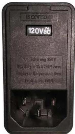
FigureA.1:TheDC205PowerEntrymodule.
A.2acvoltageselector
TheDC205linevoltageselectionisindicatedbythewhitenumber visiblenearthetopofthepowerentrymodule.Intheimageabove, thelinevoltageselectionisshowing120V.Availablesettingsare 100V,120V,220V,and240V.
The following steps describe how to change the voltage selection:
-
Disconnect and removethe powercord.
-
Openthefusecoverusingasmallbladescrewdriverorsimilar tool, insertedatthepointshown.

- Insert the tool into the voltages of selection slot and remove the selector wheel from the housing.

-
Orienttheselectorwheelsothatthedesiredlinevoltagewill showthroughthewindow.
-
Replacethewheel into the power entry module and close the covordoor, ensuring these selected voltage appears in the window.
-
If necessary, replace the fuse for the appropriating based online voltage.
A.3Fuseinstallation
TheDC205usesmetricdualfuseinstallation.Wheninstallingor replacing,besuretoreplacebothfuses.
The following steps describe how to install or replace the fuse:
- Disconnectandremovethepowercord.
- Openthefusecoverusingasmallbladescrewdriverorsimilar tool.
- Insertthetoolintotheright-handsideofeachofthefuseholders, atthelocationsshowncircledbelow. Gentlyextractthe twofuseholders.

- Gentlyprytheoldfusesoutoftheholders, and insert thenew fusesin theirplace. Besuretousetwo(2)metricsize5×20mm fuses. Thefuses should sit in theholderasshown:

- Re-insert the fuseholders into the power entry module, being sure to orient the white earrows as shown on the door. Push the fuse holders all the way into them module.
6.Swingandpushtosnapthedoorbackinplace.
- PRECISIONDCVOLTAGESOURCE
- CERTIFICATION
- WARRANTY
- SERVICE
- CONTENTS
- GENERALINFORMATIONV
- 1GETTINGSTARTED1-1
- 2OPERATION
- 3ARCHITECTURE3-1
- 4REMOTEOPERATION
- 5FIELDCALIBRATION
- 6PERFORMANCEVERIFICATION6-1
- A FUSEANDACLINE
- GENERALINFORMATION
- SAFETYANDPREPARATIONFORUSE
- WARNING
- ACLINEVOLTAGE
- CAUTION
- LINECORD
- NOTATION
- WARNINGS
- SPECIFICATIONS
- OUTPUT
- ACCURACYANDSTABILITY
- NOISEANDDRIFT
- 1GETTINGSTARTED
- INTHISCHAPTER
- 1.1 HOWTOUSETHISMANUAL
- 1.2 PRELIMINARIES
- 1.2.1 EQUIPMENTNEEDED
- 1.3FIRSTEXAMPLE:TURNINGONTHEINSTRUMENT
- 1.4USERINTERFACE
- 1.5INSTRUMENTSETTINGS
- 1.5.1 SENSE
- 1.5.2 ISOLATION
- 1.5.3 SCANNING
- 1.6INTERLOCK
- 2.1 NAVIGATING THE FRONT PANEL......2-2
- 2.2SCANNING......2-11
- 2.3ERRORMESSAGES....2-15
- 2.1 NAVIGATINGTHEFRONTPANEL
- 2.1.1 POWER
- 2.1.1.1 POWER-ONFACTORYRESET
- 2.1.1.2FIELD CALIBRATION
- 2.1.1.3 RESTORECALIBRATION
- 2.1.1.4 BAUDRATE
- 2.1.1.5KEYCLICKS
- 2.1.2RANGE
- 2.1.3SELECT/ADJUST
- 2.1.4NUMERICENTRY
- 2.1.5SENSE
- 2.1.6CONFIG
- 2.1.7SCAN
- 2.1.8OUTPUT
- 2.1.9STATUS
- 2.1.10 SOURCEOUT
- 2.2 SCANNING
- 2.2.1 OVERVIEW OF SCANNING
- 2.2.2 SCAN TERMINOLOGY
- 2.2.3ARMINGSCANS
- 2.2.4TRIGGERINGSCANS
- 2.2.5TRIGINANDBUSYOUT
- 2.2.6 ENDINGORCANCELLINGSCANS
- 2.3 ERRORMESSAGES
- 2.3.1 MESSAGESATPOWERON
- 2.3.1.1 FIRMWARECORRUPTION
- 2.3.1.2 CONFIGURATIONLOST
- 2.3.2FIELDCALIBRATION
- 2.3.3 SCANNING
- 2.3.3.1 SCANRANGE
- 2.3.3.2 OUTPUTOFF
- 2.3.3.3 BEGINNING AND ENDING VOLTAGES EQUAL
- 2.3.4 INTERLOCK
- 2.3.5 UNEXPECTED RESETS
- 2.3.5.1 UNDERVOLTAGE
- 2.3.5.2 CLOCKFAILURE
- 2.3.5.3 WATCHDOG
- 2.3.5.4 RESETPINWAKEUP
- 2.3.5.5 OTHERWAKEUP
- 2.3.5.6 HARDWARE RESET
- 2.3.5.7JTAG
- 2.3.5.8 FIRMWARE
- 2.3.5.9DEBUG
- 2.3.5.10EZPORT
- 2.3.5.11 TAMPER
- 2.3.5.12UNKNOWN
- 2.3.5.13LOCKUP
- 2.3.5.14 PERIPHERAL FAILURE
- 3ARCHITECTURE
- 3.1OVERVIEW
- 3.2VOLTAGEREFERENCE
- 3.3DIGITALTOANALOGCONVERTER
- 3.4AMPLIFIERS
- 3.4.1 HIGH-RANGEAMPLIFIER
- 3.4.2 LOW-RANGEAMPLIFIER
- 3.5 REMOTESENSING
- 4.1 INDEXOFCOMMANDS
- STATUS
- 4.2ALPHABETICLISTOFCOMMANDS
- ★
- A
- B
- C
- D
- K
- L
- 0
- R
- S
- T
- V
- 4.3 INTRODUCTION
- 4.3.1 INTERFACECONFIGURATION
- 4.3.2 ISOLATION AND COMPUTERNOISE
- 4.3.3BUFFERS
- 4.4 COMMANDS
- 4.4.1 COMMANDSYNTAX
- 4.4.2 NOTATION
- 4.4.3EXAMPLES
- 4.4.4 CONFIGURATION COMMANDS
- 4.4.5 SETTING COMMANDS
- 4.4.6 SCANCOMMANDS
- 4.4.8 INTERFACE COMMANDS
- 4.4.9STATUSCOMMANDS
- 4.5STATUSMODEL
- 4.5.1STATUSBYTE(SB)
- 4.5.2 SERVICEREQUESTENABLE(SRE)
- 4.5.3 STANDARDEVENTSTATUS(ESR)
- 4.5.3.1 STANDARDEVENTSTATUSENABLE(ESE)
- 4.5.4DCSOURCESTATUS(DCCR/DCEV)
- 4.5.4.1 DCSOURCECONDITION(DCCR)
- 4.5.4.2DCSOURCEPOSITIVE/NEGATIVETRANSITION(DCPT/DCNT)
- 4.5.4.3DCSOURCEEVENT(DCEV)
- 4.5.4.4DCSOURCESTATUSENABLE(DCSE)
- 5.1 INTRODUCTIONTOFIELDCALIBRATION
- 5.2 CALIBRATIONMETHOD
- 5.3 EQUIPMENT NEEDED
- 5.4DETAILEDPROCEDURE
- 5.5 FOLLOWING FIELDCALIBRATION
- 5.6RESTORINGTHEFACTORYCALIBRATION
- 6PERFORMANCEVERIFICATION
- 6.1 INTRODUCTION TO PERFORMANCE VERIFICATION
- 6.2 EQUIPMENTNEEDED
- 6.3 VERIFICATION PROCEDURE
- 6.4 PERFORMANCETESTRECORDS
- APPENDIXAFUSEINSTALLATIONANDACLINESELECT
- A.1POWERENTRYMODULE
- A.2ACVOLTAGESELECTOR
- A.3FUSEINSTALLATION
Brand : SRS
Model : DC205
Category : Measuring equipment