
TL-WA3001 - Access Point TP-LINK - Free user manual and instructions
Find the device manual for free TL-WA3001 TP-LINK in PDF.


| Product Type | Wireless Access Point |
| Brand | TP-Link |
| Model | TL-WA3001 |
| Wireless Standards | IEEE 802.11ac/n/g/b/a |
| Frequency Band | 2.4 GHz and 5 GHz |
| Maximum Data Rate | Up to 1200 Mbps |
| Ethernet Ports | 1× 10/100/1000 Mbps RJ45 |
| Power Supply | 5V DC, 1A via microUSB |
| Dimensions | 120×120×30 mm |
| Weight | 200 g |
| Main Functions | Access point mode, WDS bridging, DHCP server, firewall |
| Security | WPA/WPA2/WPA3 encryption, MAC filter, SSID broadcast control |
| Maintenance | Clean with soft dry cloth; avoid liquids |
| Spare Parts | Not available separately; device must be replaced |
| Repairability | Not user-serviceable; contact support |
Frequently Asked Questions - TL-WA3001 TP-LINK
User questions about TL-WA3001 TP-LINK
0 question about this device. Answer the ones you know or ask your own.
Ask a new question about this device
Download the instructions for your Access Point in PDF format for free! Find your manual TL-WA3001 - TP-LINK and take your electronic device back in hand. On this page are published all the documents necessary for the use of your device. TL-WA3001 by TP-LINK.
USER MANUAL TL-WA3001 TP-LINK
AX3000 Gigabit Wi-Fi 6 Access Point
TL-WA3001
Contents
About This Guide....1
Chapter 1. Get to Know About Your Access Point....3
- Product Overview....4 1.2. Panel Layout.... 4 1.2.1.Top View 4 1.2.2.Back Panel 5
Chapter 2. Set Up Internet Connection ....7
2.1. Position Your Access Point....8 2.2. Set Up Your Access Point 9 2. 2. 1. Access Point Mode (Default). 9 2. 2. 2.Range Extender Mode....10 2. 2. 3.Client Mode....11 2. 2. 4.Multi-SSID Mode ..... 12
Chapter 3. TP-Link Cloud Service (for Access Point Mode)....14
3.1. Register a TP-Link ID.... 15 3.2. Change Your TP-Link ID Information....15 3.3. Manage the User TP-Link IDs 16 3. 3. 1. Add TP-Link ID to Manage the Access Point ..... 17 3. 3. 2. Remove TP-Link ID(s) from Managing the Access Point ..... 17
3.4. Manage the Access Point via the TP-Link Tether App 18
Chapter 4. Wireless Settings.... 19
4.1. Specify Wireless Settings....20 4. 1. 1. Access Point Mode.....20 4. 1. 2.Range Extender Mode.....22 4. 1. 3.Client Mode....24 4. 1. 4.Multi-SSID Mode ..... 25
- Use WPS for Wireless Connection (for Access Point/Multi-SSID Mode) ..... 28
- Check Advanced Wireless Settings (for Access Point/Multi-SSID Mode) ..... 29
- Monitor Wireless Statistics (for Access Point/Multi-SSID Mode) .....30
- Monitor the Traffic Throughput (for Access Point/Multi-SSID Mode) ..... 31
Chapter 5. Portal (for Access Point/Multi-SSID Mode) ...... 32
Chapter 6. Access Control ...... 35
Chapter 7. Customize Network Settings.... 39
7.1. Change the LAN Settings 40
7.2. Specify DHCP Server Settings....40
Chapter 8. Manage Your Access Point....42
8.1. Set the System Time and Language....43 8.2. Control LEDs 45 8.3. Configure the SNMP Agent 46 8.4. Configure the Ping Watchdog....47 8.5. Update the Firmware....48
8.5.1.Auto Update ....48 8.5.2.Online Update....49 8.5.3.Local Update....50
8.6. Backup and Restore Configuration Settings 50
8.7. Reboot the Access Point....51 8.8. Change the Login Password 52 8.9. Password Recovery....53 8.10. Local Management ....53 8.11. Test the Network Connectivity ..... 55 8.12. System Log....56
FAQ 59
About This Guide
This guide is a complement of Quick Installation Guide. The Quick Installation Guide instructs you on quick internet setup, and this guide provides details of each function and shows you the way to configure these functions appropriate to your needs.
Note: Features available in the product may vary by model and software version. The product availability may also vary by region or ISP. All images, steps, and descriptions in this guide are only examples and may not reflect your actual product experience.
Conventions
In this guide the following conventions are used:
| Convention Description | |
| Underlined | Underlined words or phrases are hyperlinks. You can click to redirect to a website or a specific section. |
| Teal | Contents to be emphasized and texts on the web page are in teal, including the menus, items, buttons, etc. |
| > | The menu structures to show the path to load the corresponding page. For example, System > Firmware Update means the Firmware Update page is located in the System tab. |
| Note: | Ignoring this type of note might result in a malfunction or damage to the device. |
| Tips: | Indicates important information that helps you make better use of your device. |
| symbols on the web page | Click to edit the corresponding entry.Click to delete the corresponding entry.Click to enable or disable the corresponding entry.Click to view more information about items on the page. |
More Info
The latest software, management app and utility can be found at Download Center at https://www.tp-link.com/support/download.
The Quick Installation Guide can be found where you find this guide or inside the product package.
Specifications can be found on the product page at https://www.tp-link.com.
TP-Link Community is provided for you to discuss our products and share knowledge at https://community.tp-link.com.
Our Technical Support contact information can be found at the Contact Technical Support page at https://www.tp-link.com/support.
*Maximum wireless signal rates are the physical rates derived from IEEE Standard 802.11 specifications. Actual wireless data throughput and wireless coverage are not guaranteed and will vary as a result of 1) environmental factors, including building materials, physical objects, and obstacles, 2) network conditions, including local interference, volume and density of traffic, product location, network complexity, and network overhead, and 3) client limitations, including rated performance, location, connection, quality, and client condition.
*Use of Wi-Fi 6 (802.11ax), and features including OFDMA, 1024-QAM, and HT160 require clients to also support the corresponding features.
*Saving clients' battery power requires clients to also support the 802.11ax Wi-Fi standard. Actual power reduction may vary as a result of network conditions, client limitations, and environmental factors.
*Use of WPA3 requires clients to also support the corresponding feature.
*This device may not support all the mandatory features as ratified in Draft 3.0 of IEEE 802.11ax specification.
*Further software upgrades for feature availability may be required.
Chapter 1
Get to Know About Your Access Point
This chapter introduces what the access point can do and shows its appearance. It contains the following sections:
- Product Overview
- Panel Layout
1.1 Product Overview
The TP-Link access point, with multiple operation modes, is designed to establish or expand a scalable high-speed wireless network or to connect your Ethernet enabled device to a wireless network, such as the game console, digital media adapter, printer, or network attached storage device. The access point supports a host of different functions that make your wireless networking experience more flexible than ever before. Now, you can enjoy a better internet experience when downloading, gaming, video streaming or with any other application that you may wish to use.
1.2 Panel Layout
1.2.1 Top View

The access point's LEDs (view from left to right) are located on the front. You can check the access point's working status by following the LED Explanation table.
LED Explanation
| Name Status Indication | ||
| [6473](Power) | On Power is on. | |
| Blinking once every second | The system is starting up or updating firmware. Do not disconnect or power off your access point. | |
| Blinking twice every second | WPS connection is in progress. This may take up to 2 minutes. | |
| Off Power is off. | ||
| [6530](2.4 GHz) | On/Off The 2.4 GHz wireless band is enabled or disabled. | |
| [4291](5 GHz) | On/Off The 5 GHz wireless band is enabled or disabled. | |
| [6714](Internet) | Green Internet is available. | |
| Orange | The Ethernet port is connected but internet is not available. | |
| Off | The Ethernet port is not connected and internet is not available. | |
1.2.2. Back Panel
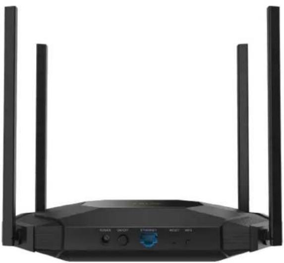
The following parts (view from left to right) are located on the back panel.
| Ports or Buttons Description | |
| POWER Port | For connecting the access point to a power socket via the provided power adapter. |
| ON/OFF Button Press this button to power on or off the access point. | |
| ETHERNET Port | For connecting an Ethernet enabled device, such as a router or desktop. |
| RESET | Press and hold this button until the Power LED blinks to reset the access point to its factory default settings. |
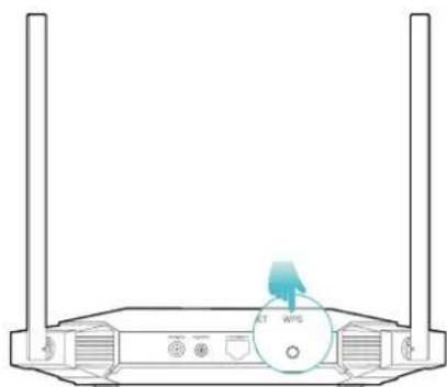
| WPS | Press this button and immediately press the WPS button on another device to quickly establish a wireless connection. |
| Antennas | Used for wireless operation and data transmitting. Upright them for the best Wi-Fi performance. |
Chapter 2
Set Up Internet Connection
This chapter introduces how to quickly set up the access point.
It contains the following sections:
• Position Your Access Point - Set Up Your Access Point
2.1. Position Your Access Point
- The product should not be located in a place where it will be exposed to moisture or excessive heat.
- Place the access point in a location where it can be connected to various devices as well as to a power source.
- Make sure the cables and power cord are safely placed out of the way so they do not create a tripping hazard.
- The access point can be placed on a shelf or desktop.
- Keep the access point away from devices with strong electromagnetic interference, such as Bluetooth devices, cordless phones and microwaves.
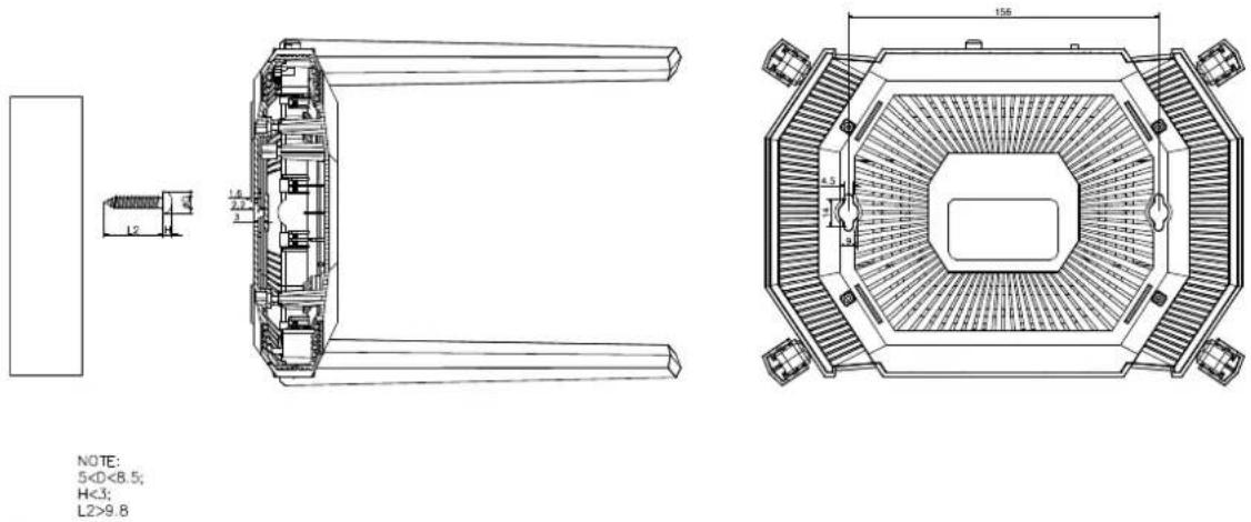
- Generally, the access point is placed on a horizontal surface, such as on a shelf or desktop. The device also can be mounted on the wall as shown in the following figure.
Note:
The diameter of the screw head, 5 mm < D < 8.5 mm, and the distance between two screws is 156 mm. The screw that projects from the wall needs about 3.8 mm of clearance, and the length of the screw needs to be at least 9.8 mm to withstand the weight of the product.
- If the access point is located far from a power outlet, you can power the device with the provided passive PoE injector.
Note:
The passive PoE injector supports a cable length up to 30 meters, but the value may vary due to the environment.
Power on via Passive PoE Injector![graph LR A["Internet"] --> B["Access Point"] B --> C["Passive PoE Injector Existing Router"] C --> D["Mobile Device"] B --> E["Wireless Signal"] C --> F["Wireless Signal"] style A fill:#f9f,stroke:#333 style B fill:#ccf,stroke:#333 style C fill:#cfc,stroke:#333 style D fill:#fcc,stroke:#333 style E…](/content/2026/06/1396708/images/6c3aeadaf43f58a7e7d7ebd1f9fcca7f891bd9076e2a3b78bec1ead8260467af.jpg)
2.2. Set Up Your Access Point
There are four operation modes supported by this access point: Access Point, Range Extender, Client, and Multi-SSID. Please determine which operation mode you need and complete the corresponding setup.
2.2.1. Access Point Mode (Default)
In this mode, the access point transforms your existing wired network to a wireless one. This mode is suitable for dorm rooms or homes where there's already a wired router but you need a wireless network.
![graph LR A["Internet"] --> B["Existing Router"] B --> C["Access Point"] C --> D["Wireless Network"] D --> E["Mobile Device"] D --> F["Computer"]](/content/2026/06/1396708/images/7ed5538b9b2e7d78fc508874bbf7436467ea5033265a023693bed159dbdc369f.jpg)
- Connect the access point according to Step A to D in the diagram.
- Turn on the power, and wait for about 2 minutes until the Power and Wi-Fi LEDs are lit and stable.
- Use the default SSID and Password printed on the label of the access point to join its Wi-Fi network.
Note:
You can surf the internet now. For your wireless network security, it is recommended to change the default SSID (network name) and the password of your Wi-Fi network. To do so, perform the following steps.
- Launch a web browser and enter http://tplinkap.net. Create a password to log in.
Note:
If the login window does not appear, please refer to the FAQ section.
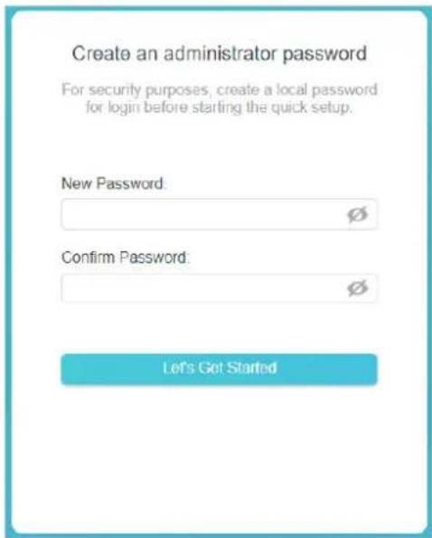
- Follow the step-by-step instructions to complete the configuration.
- Now, reconnect your wireless devices to the new Wi-Fi network and enjoy the internet!
2.2.2. Range Extender Mode
In this mode, the access point extends the range of an existing Wi-Fi network. This mode is suitable when you are in a Wi-Fi dead-zone or a place with weak wireless signal, and you want to have a larger effective range of the wireless signal throughout your home or office.
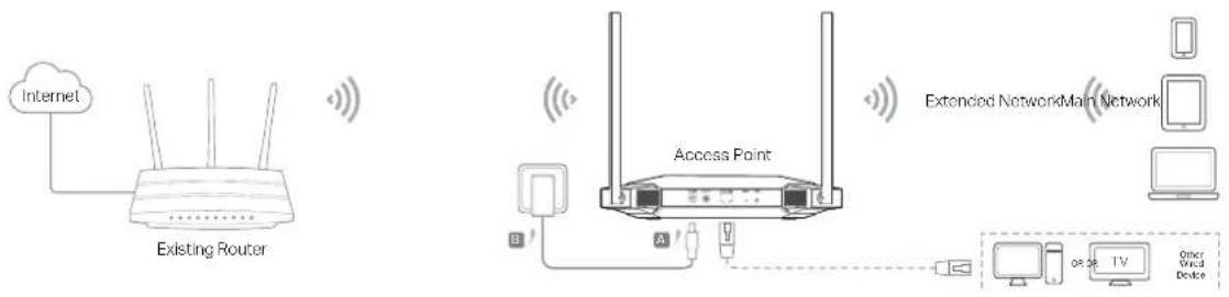
- Connect the access point according to Step A and B in the diagram.
- Turn on the power, and wait for about 2 minutes until the Power and Wi-Fi LEDs are lit and stable.
- Connect your computer to the access point via an Ethernet cable.
- Launch a web browser and enter http://tplinkap.net. Create a password to log in.
Note:
If the login window does not appear, please refer to the FAQ section.

- Click Change Mode and switch to the Range Extender mode.
- Wait until the access point reboots, then log in again.
- Follow the step-by-step instructions to complete the configuration.
- Relocate the access point about halfway between your host router and the Wi-Fi dead zone. Tip: To maximize the signal strength, refer to the FAQ section.
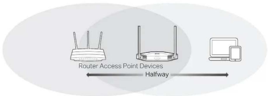
- Now, connect your devices to the access point wirelessly or via an Ethernet cable, and enjoy the internet!
2.2.3. Client Mode
In this mode, the access point connects your wired device to a wireless network. This mode is suitable when you have a wired device with an Ethernet port and no wireless capability, for example, a smart TV or game console and you want to connect it to the internet wirelessly.
![graph LR A["Internet"] --> B["Existing Router"] B --> C["Main Network"] C --> D["Access Point"] D --> E["Other Wired Device"] D --> F["Switch A"] D --> G["Switch B"] D --> H["Switch C"] D --> I["Switch D"]](/content/2026/06/1396708/images/f1b681d720e9160e254b1f7465b410e78aec23415f288163c51b7cba249907be.jpg)
- Connect the access point according to Step A to B in the diagram.
- Turn on the power, and wait for about 2 minutes until the Power and Wi-Fi LEDs are lit and stable.
- Connect your computer to the access point via an Ethernet cable.
- Launch a web browser and enter http://tplinkap.net. Create a password to log in.
Note:
If the login window does not appear, please refer to the FAQ section.
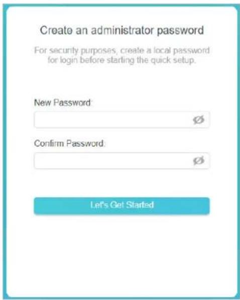
- Click Change Mode and switch to the Client mode.
- Wait until the access point reboots, then log in again.
- Follow the step-by-step instructions to complete the configuration.
- Now, connect your wired device to the access point via an Ethernet cable, and enjoy the internet!
2.2.4. Multi-SSID Mode
In this mode, the access point creates multiple wireless networks to provide different security and VLAN (Virtual Local Area Network) groups. This mode is suitable when you want your devices connected to different wireless networks and become isolated by VLANs.
![graph LR A["Internet"] --> B["Existing Router"] B --> C["Access Point"] C --> D["SSID 1 for VLAN 1"] C --> E["SSID 2 for VLAN 2"] C --> F["SSID 3 for VLAN 3"] C --> G["SSID 4 for VLAN 4"] style A fill:#f9f,stroke:#333 style B fill:#ccf,stroke:#333 style C fill:#cfc,stroke:#333 style D fill:#ffc,stro…](/content/2026/06/1396708/images/1512b65d775eb00474068279fc07b05ad76d397ab1ff72b8283a3f20ec5c2d84.jpg)
- Connect the access point according to Step A to D in the diagram.
- Turn on the power, and wait for about 2 minutes until the Power and Wi-Fi LEDs are lit and stable.
- Use the default SSID and Password printed on the label of the access point to join its Wi-Fi network.
- Launch a web browser and enter http://tplinkap.net. Create a password to log in.
Note:
If the login window does not appear, please refer to the FAQ section.
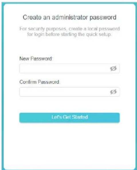
- Click Change Mode and switch to the Multi-SSID mode.
- Wait until the access point reboots, then reconnect to the access point and log in again.
- Follow the step-by-step instructions to complete the configuration.
- Now, connect your wireless devices to the Wi-Fi networks and enjoy the internet!
Tip:
If you want to isolate different networks, go to Wireless > Wireless Settings, click the edit icon of each SSID entry and set different VLAN IDs.
TP-Link Cloud Service
(for Access Point Mode)
TP-Link Cloud service provides a better way to manage your cloud devices. Log in to your access point with a TP-Link ID, and you can easily monitor and manage your home network when you are out and about via the Tether app. To ensure that your access point stays new and gets better over time, the TP-Link Cloud will notify you when an important firmware upgrade is available. Surely you can also manage multiple TP-Link Cloud devices with a single TP-Link ID.
This chapter introduces how to register a new TP-Link ID, bind or unbind TP-Link IDs to manage your access point, and the Tether app with which you can manage your home network no matter where you may find yourself.
It contains the following sections:
- Register a TP-Link ID • Change Your TP-Link ID Information
- Manage the User TP-Link IDs
- Manage the Access Point via the TP-Link Tether App
3. 1. Register a TP-Link ID
- Visit http://tplinkap.net, and log in with the password you set for the access point.
- Go to System > TP-Link ID or click TP-Link ID in the upper right corner of the page.
- Click Sign Up and follow the instructions to register a TP-Link ID.
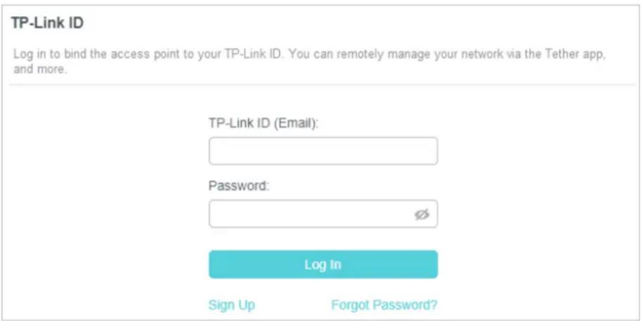
- After activating your TP-Link ID, come back to the TP-Link ID page to log in. The TP-Link ID used to log in to the access point for the first time will be automatically bound as an Admin.
Note:
• To learn more about the Admin and User TP-Link ID, refer to Manage the User TP-Link IDs. - Once you have registered a TP-Link ID on the web management page, you can only register another TP-Link ID via the Tether APP. Please refer to Manage the Access Point via the TP-Link Tether App to install the app. - If you want to unbind the admin TP-Link ID from your access point, please go to Advanced > TP-Link ID, an click Unbind in the Device Information section.
3.2. Change Your TP-Link ID Information
Follow the steps below to change your email address and password of your TP-Link ID as needed.
- Visit http://tplinkap.net, and log in with the password you set for the access point.
- Go to System > TP-Link ID, and focus on the Account Information section.
• To change your email address:
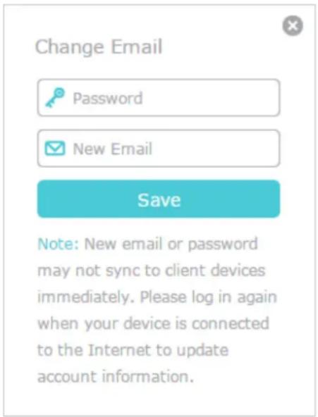
- Click the edit icon behind the Email.
- Enter the password of your TP-Link ID, then a new email address. And click SAVE.
• To change your password:
- Click the edit icon behind the Password.
- Enter the current password, then a new password twice. And click SAVE.

3. Manage the User TP-Link IDs
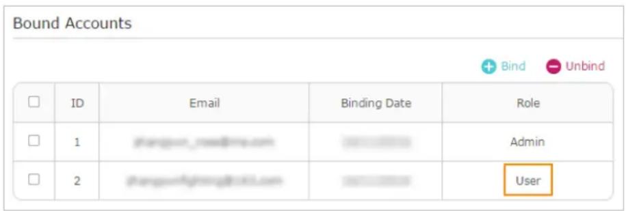
The TP-Link ID used to log in to the access point for the first time will be automatically bound as the Admin account. An admin account can add or remove other TP-Link IDs
to or from the same access point as Users. All accounts can monitor and manage the access point locally or remotely, but user accounts cannot:
- Reset the access point to its factory default settings either on the web management page or in the Tether app.
- Add/remove other TP-Link IDs to/from the access point.
3.3.1 Add TP-Link ID to Manage the Access Point
- Visit http://tplinkap.net, and log in with the password you set for the access point.
- Go to System > TP-Link ID, and focus on the Bound Accounts section.
- Click + Bind, enter another TP-Link ID as needed and click SAVE.
Note: If you need another TP-Link ID, please register a new one via the Tether app. Refer to Manage the Access Point via the TP-Link Tether App to install the app and register a new TP-Link ID.
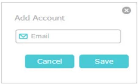
- The new TP-Link ID will be displayed in the Bound Accounts table as a User.
3.3.2 Remove TP-Link ID(s) from Managing the Access Point
- Visit http://tplinkap.net, and log in with the password you set for the access point.
- Go to System > TP-Link ID, and focus on the Bound Accounts section.
- Tick the checkbox(es) of the TP-Link ID(s) you want to remove and click Unbind.

3.4 Manage the Access Point via the TP-Link Tether App
The Tether app runs on iOS and Android devices, such as smartphones and tablets.
- Launch the Apple App Store or Google Play store and search "TP-Link Tether" or simply scan the QR code to download and install the app.
OR
→

- Launch the Tether app and log in with your TP-Link ID.
Note: If you don't have a TP-Link ID, create one first. 3. Connect your device to the access point's wireless network. 4. Go back to the Tether app, select your access point and log in with the password you set for the access point. 5. Manage your access point as needed.
Note:
If you need to remotely access your access point from your smart devices, you need to:
- Log in with your TP-Link ID. If you don't have one, refer to Register a TP-Link ID. • Make sure your smartphone or tablet can access the internet with cellular data or a Wi-Fi network.
Chapter 4
Wireless Settings
This chapter guides you on how to configure the wireless settings.
It contains the following sections:
- Specify Wireless Settings
- Use WPS for Wireless Connection (for Access Point/Multi-SSID Mode)
- Check Advanced Wireless Settings (for Access Point/Multi-SSID Mode) • Monitor Wireless Statistics (for Access Point/Multi-SSID Mode) • Monitor the Traffic Throughput (for Access Point/Multi-SSID Mode)
4. 1. Specify Wireless Settings
The access point's wireless network names (SSIDs), password, and security option are preset in the factory. The preset SSIDs and password can be found on the label of the access point.
Wireless settings differ with operation mode.
4.1.1. Access Point Mode
When the device works in Access Point mode, you can customize its wireless network.
- Visit http://tplinkap.net, and log in with the password you set for the access point.
- Go to Wireless > Wireless Settings.
![Wireless Settings Personalize settings for each band or enable Smart Connect to configure the same settings for all bands. OFDMA: Enable ? TWT: Enable ? Smart Connect: Enable ? 2.4GHz: Enable Share Network Network Name (SSID): TP-Link_3829 Hide SSID Security: WPA2-PSK[AES] Password: Transmit Power:…](/content/2026/06/1396708/images/66a10ec4ff4bc523ea253d6922081e3435b2d00c3e11c78d81a42af18be474a1.jpg)
• To enable or disable OFDMA:
OFDMA enables multiple users to transmit data simultaneously, and thus greatly improves speed and efficiency. Note that only when your clients also support OFDMA can you fully enjoy the benefits. It is disabled by default.
- Go to Wireless > Wireless Settings.
- Enable OFDMA.
• To enable or disable TWT:
TWT (Target Wake Time) allows 802.11ax access points and clients to negotiate their periods to transmit and receive data packets. Clients only wake up at TWT sessions and remain in sleep mode for the rest of the time, which significantly extends their battery life. It is disabled by default.
- Go to Wireless > Wireless Settings.
- Enable TWT.
• To use the Smart Connect function:
Smart Connect combines the 2.4 GHz and 5 GHz bands and assigns your devices between them to balance network demands.
- Go to Wireless > Wireless Settings.
- Enable Smart Connect.
Smart Connect:
Enable

- Keep the default values or set a new SSID and password, and click SAVE. This SSID and password will be applied for the 2.4 GHz and 5 GHz wireless networks. If you want to configure the wireless settings separately for each band, deselect the checkbox to disable this feature.
- To enable or disable a wireless band:
- Go to Wireless > Wireless Settings.
- The wireless bands are enabled by default. If you want to disable a wireless band, just deselect its Enable checkbox.
- To change the wireless network name (SSID) and wireless password:
- Go to Wireless > Wireless Settings.
- Create a new SSID in Network Name (SSID) and customize the password for the network in Password. The value is case-sensitive.
Note: If you change the wireless settings with a wireless device, you will be disconnected when the settings are effective. Please write down the new SSID and password for future use.
- To hide SSID:
- Go to Wireless > Wireless Settings.
- Select Hide SSID, then your SSID won't display when wireless devices scan for wireless networks and you will need to manually enter the SSID to join the network.
• To change the security option:
- Go to Wireless > Wireless Settings.
- Select an option from the Security drop-down list. We recommend you don't change the default settings unless necessary.
• To change the transmit power:
- Go to Wireless > Wireless Settings.
- Select an option from the Transmit Power drop-down list.
- To change channel and mode settings:
- Go to Wireless > Wireless Settings.
- Make sure Smart Connect is disabled. Channel and mode settings are not available when Smart Connect is enabled.
- Select a Channel Width (bandwidth) for the wireless network. It is recommended to just leave it as default.
- Select an operating Channel for the wireless network. It is recommended to leave the channel to Auto if you are not experiencing the intermittent wireless connection issue.
- Select a transmission Mode according to your wireless client devices. It is recommended to just leave it as default.
- Click SAVE.
4.1.2. Range Extender Mode
When the device works in Range Extender mode, you can reselect the networks to extend and customize the extended networks.
- Visit http://tplinkap.net, and log in with the password you set for the access point.
- Go to Wireless > Wireless Settings.
- In the Connect to Main Network section, select the 2.4GHz and/or 5GHz network(s), click Wi-Fi SCANNER to find and select the network to extend. If the selected network is encrypted, enter the network password.
Connect to Main Network
Connect the access point to your main network.
2.4GHz

Enable
Wi-Fi SCANNER
Main Network SSID
home
MAC Address:


Lock to AP
Security

WPA/WPA2-Personal

Password:


5GHz

Enable
Wi-Fi SCANNER
Main Network SSID
home5G
MAC Address


Lock to AP
Security

PA/WPA2-Personal

Password


- In the Extended Network section, customize the extended networks as you need. You can:
- Enable or disable a wireless network.
- Change the extended SSIDs or copy main network SSIDs. Note: Extended passwords are the same as the main network passwords and cannot be changed.
- Select Hide SSID for a network, then your SSID won't display when wireless devices scan for wireless networks and you will need to manually enter the SSID to join the network.

- Click SAVE.
4. 1. 3. Client Mode
When the device works in Client mode, you can connect to another network.
- Visit http://tplinkap.net, and log in with the password you set for the access point.
- Go to Wireless > Wireless Settings.

- Select the 2.4GHz or 5GHz band.
- Click Wi-Fi SCANNER to find and select the network to connect. Main network SSID and MAC address will be automatically filled in.
- (Optional) If you want to lock the connection to the specified AP, enable Lock to AP. The access point will not switch connection to other APs even if they use the same network name and password as the specified one.
- Enter the network password.
7. Click SAVE.
4. 1. 4. Multi-SSID Mode
When the device works in Multi-SSID mode, you can customize and isolate multiple wireless networks.
- Visit http://tplinkap.net, and log in with the password you set for the access point.
- Go to Wireless > Wireless Settings.
![Wireless Settings Personalize wireless settings as you need OFDMA: Enable ? TWT: Enable ? 2.4GHz 5GHz Band Network Name Password Security Status Modify (SSID) 2.4GHz-1 TP-Link_3829 WPA2-PSK[AES] 2.4GHz-2 TP-Link_3829_2 WPA2-PSK[AES] 2.4GHz-3 TP-Link_3829_3 WPA2-PSK[AES] 2.4GHz-4 TP-Link_3829_4 WPA2-…](/content/2026/06/1396708/images/9f1f0be982f6e0665432dfc65394fb644f7b382996e95eb0fc5ff095334791b2.jpg)
• To enable or disable OFDMA:
OFDMA enables multiple users to transmit data simultaneously, and thus greatly improves speed and efficiency. Noted that only when your clients also support OFDMA, can you fully enjoy the benefits. It is disabled by default.
- Go to Wireless > Wireless Settings.
- Enable OFDMA. • To enable or disable TWT:
TWT (Target Wake Time) allows 802.11ax access points and clients to negotiate their periods to transmit and receive data packets. Clients only wake up at TWT sessions and remain in sleep mode for the rest of the time, which significantly extend their battery life. It is disabled by default.
- Go to Wireless > Wireless Settings.
- Enable TWT.
• To customize a wireless network:
- Go to Wireless > Wireless Settings.
- Click 2.4GHz or 5 GHz, select a network and click
![Edit 2.4GHz-1: Enable Extended SSID: TP-Link_3829 Hide SSID VLAN: 1 ? Security: WPA2-PSK[AES] Password: CANCEL SAVE](/content/2026/06/1396708/images/00267c61a38a2e814d5ffd9b8f4585bbfc602b8b910cf939731d2662803015b4.jpg)
- Customize the network according to your needs. You can:
- Enable or disable the network.
- Change the extended SSID, password, and security option.
- Select Hide SSID for the network, then your SSID won't display when wireless devices scan for wireless networks and you will need to manually enter the SSID to join the network.
- Click SAVE.
• To isolate wireless networks:
- Go to Wireless > Wireless Settings.
- Click the checkbox of each SSID entry and set different VLAN IDs. Only the networks with the same VLAN ID can access each other. Wireless networks will be isolated by VLANs.
![Edit 2.4GHz-1: Enable Extended SSID: TP-Link_3829 Hide SSID VLAN: 1 Security: WPA2.PSK[AES] Password: CANCEL SAVE](/content/2026/06/1396708/images/4d8e8daefa10de51501de610c12446e534af1fc737b29f0725991fad6921fceb.jpg)
- Click SAVE.
• To change the transmit power:
- Go to Wireless > Wireless Settings.
- Click 2.4GHz or 5 GHz.
- Select an option from the Transmit Power drop-down list.
• To change channel settings:
- Go to Wireless > Wireless Settings.
- Click 2.4GHz or 5 GHz.
- Select a Channel Width (bandwidth) for the wireless network. It is recommended to just leave it as default.
- Select an operating Channel for the wireless network. It is recommended to leave the channel to Auto if you are not experiencing the intermittent wireless connection issue.
- Click SAVE.
• To change the transmission mode:
- Go to Wireless > Wireless Settings.
- Click 2.4GHz or 5 GHz.
- Select a transmission Mode according to your wireless client devices. It is recommended to just leave it as default.
- Click SAVE.
4. 2. Use WPS for Wireless Connection (for Access Point/Multi-SSID Mode)
Wi-Fi Protected Setup (WPS) provides an easier approach to set up a security-protected Wi-Fi connection.
- Visit http://tplinkap.net, and log in with the password you set for the access point.
- Go to Wireless > WPS.
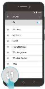
- Follow one of the following methods to connect your WPS-enabled client to the access point's Wi-Fi network.
- Connect via the client's PIN
1) Click Client's PIN.
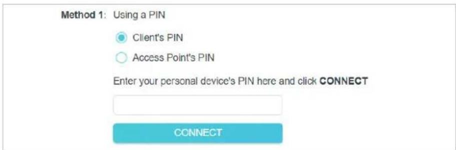
2) Enter your client's PIN, and then click CONNECT. 3) A success message will appear on the WPS page when the device successfully join the access point's network.
- Connect via the access point's PIN
1) Click Access Point's PIN.

2) Check your access point's PIN. You can use the default PIN or generate a new one. 3) Enter this PIN on your client for it to join the access point's network.
- Connect via the Start button on the WPS page
1) Click the Start button on the WPS page.
Method 2: Using the button below
Click the button below, then enable WPS on your personal device within 2 minutes.

2) Within 2 minutes, enable WPS on your client. 3) A success message will appear on the WPS page when the device successfully joins the access point's network.
- Connect via the WPS button on the access point
1) Press the WPS button on the back panel of the access point. 2) Within 2 minutes, enable WPS on your client. The client will connect to the access point.
4.3. Check Advanced Wireless Settings (for Access Point/Multi-SSID Mode)
You can check advanced wireless settings for the device. It is recommended that you keep the default settings. Improper settings may affect network performance.
- Visit http://tplinkap.net, and log in with the password you set for the access point.
- Go to Wireless > Wireless Advanced.
- Check the advanced settings of your wireless network.
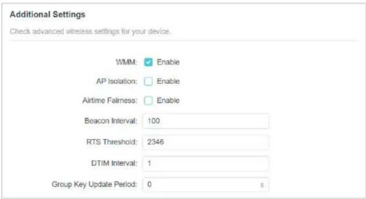
- WMM – This function can guarantee that packets with high-priority messages are transmitted preferentially.
- AP Isolation – This function isolates all connected wireless stations so that wireless stations cannot access each other through WLAN.
- Airtime Fairness – This function can improve the overall network performance by sacrificing a little bit of network time on your slow devices.
- Beacon Interval – Enter a value between 40 and 1000 milliseconds to determine the duration between beacon packets that are broadcast by the access point to synchronize the wireless network. The default value is 100 milliseconds.
- RTS Threshold – Enter a value between 1 and 2346 to determine the packet size of data transmission through the access point. If the packet is larger than the specified threshold, the access point will send RTS (Request to Send) frames to a particular receiving station and negotiate the sending of a data frame. Otherwise, the packet will be sent immediately. The default value is 2346.
- DTIM Interval – This value determines the interval of the Delivery Traffic Indication Message (DTIM). A DTIM field is a countdown field informing clients of the next window for listening to broadcast and multicast messages. When the access point has buffered broadcast or multicast messages for associated clients, it sends the next DTIM with a DTIM Interval value. Enter a value between 1 and 15 Beacon Intervals. The default value is 1, indicating that the DTIM Interval is the same as Beacon Interval.
- Group Key Update Period – Enter the number of seconds (minimum 30) to control the time interval for the encryption key automatic renewal. The default value is 0, indicating no key renewal.
4.4 Monitor Wireless Statistics (for Access Point/Multi-SSID Mode)
The Wireless Statistics page displays the data statistics of wireless clients.
- Visit http://tplinkap.net, and log in with the password you set for the access point.
- Go to Wireless > Wireless Statistics.
- View the data statistics of wireless clients.
![Wireless Statistics View the data statistics of wireless clients. Total Clients: 2 Type Information Connection Type Security Received Bytes Sent Bytes M2012K11AC 9C-5A-B1-A6-DA-15 5GHz WPA2-PSK[AES] 3.5KB 19.0KB UNKNOWN C2-92-DC-4E-78-B7 5GHz WPA2-PSK[AES] 8.6KB 9.7KB](/content/2026/06/1396708/images/03907239f56aba840e4dc9d4309594b701ac74bbf47b0942b7d2075db92ae7ec.jpg)
4.5 Monitor the Traffic Throughput (for Access Point/Multi-SSID Mode)
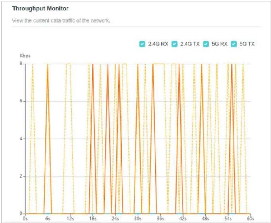
The throughput chart displays the current data traffic of the network.
- Visit http://tplinkap.net, and log in with the password you set for the access point.
- Go to Wireless > Throughput Monitor.
- Select 2.4G RX, 2.4G TX, 5G RX and/or 5G TX to view the data rates.
Chapter 5
Portal
(for Access Point/Multi-SSID Mode)
Imagine that you run a small shop and provide Wi-Fi access for your customers. You want to seize every opportunity to promote your shop, which makes portal authentication an excellent choice. Customers will be directed to a web page for access verification, on which your personalized promotion is displayed. Moreover, you can specify a web link so that the newly connected guest will be redirected to, for example, the official website of your shop.
- Visit http://tplinkap.net, and log in with the password you set for the access point.
- Go to Wireless > Portal.
- Enable Portal.
Note: The figure below uses the Portal page of the Access Point mode as an example. In the Multi-SSID mode, more Wi-Fi networks will be available to select.
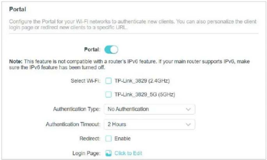
- Select the Wi-Fi networks for portal authentication.
- Select the Authentication Type.
- If you select No Authentication, clients can access the specified Wi-Fi networks without any authentication.
- If you select Simple Password, you can set a password for clients.
- Select a time for Authentication Timeout. A client has to reconnect to the network when its authentication expires.
- (Optional) Enable Redirect and enter your desired website. Newly connected clients will be redirected to the specified website.
- (Optional) Click to edit the Login Page. You can personalize the appearance and content of the login page for newly connected clients.

- Click SAVE.
Chapter 6
Access Control
Access Control is used to block or allow specific client devices to access your network (via wired or wireless) based on a list of blocked devices (Blacklist) or allowed devices (Whitelist).
- Visit http://tplinkap.net, and log in with the password you set for the access point.
- Go to Internet > Access Control.
Note: Access Control is not available in Client mode.
- Turn on Access Control.
- Select the access mode to either block (recommended) or allow specific device(s).
To block specific devices:
1) Click Blacklist.
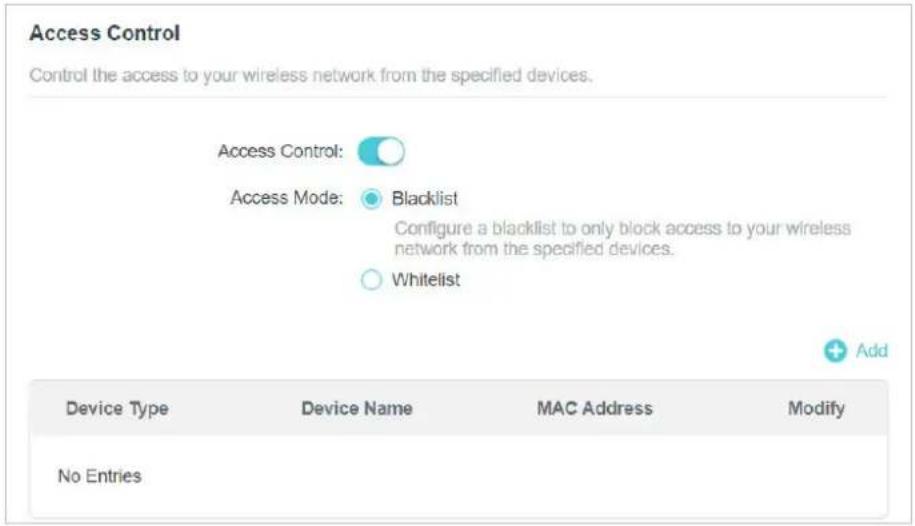
2) Click Add.
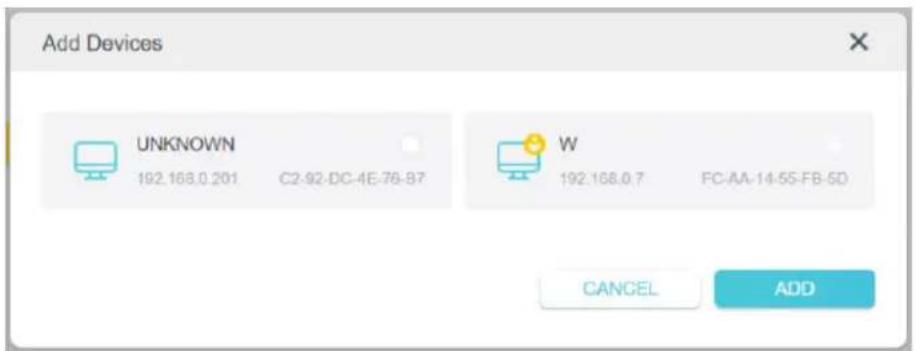
3) Select the devices you want to block and click ADD.
To allow specific devices:
1) Click Whitelist and click SAVE. Your current device will be automatically added to the whitelist.
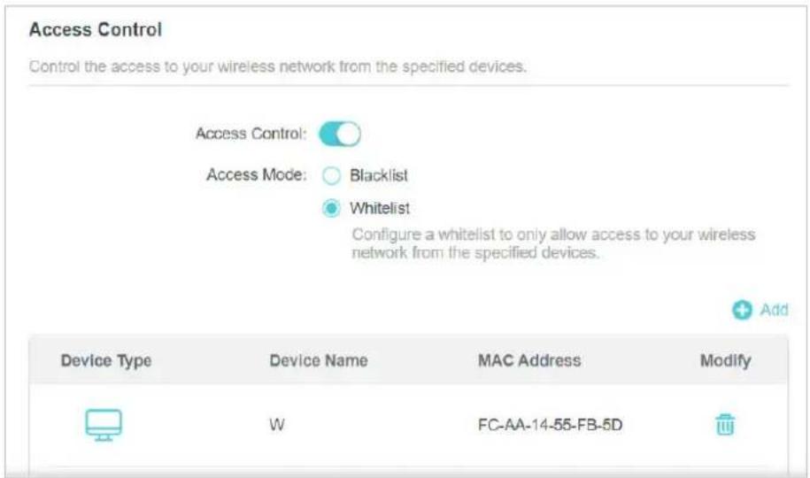
2) Click Add to add other devices you want to allow. 3) Click Select From Device List, choose devices, then click ADD.
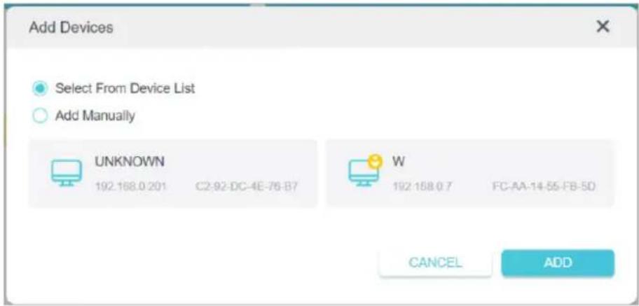
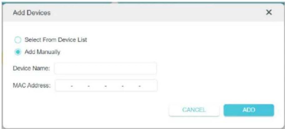
Alternatively, click Add Manually, enter the device name and MAC address, then click ADD.
Done!
Now you can block or allow specific client devices to access your network using the Blacklist or Whitelist.
Chapter 7
Customize Network Settings
This chapter introduces how to customize your network settings.
It contains the following sections:
- Change the LAN Settings
- Specify DHCP Server Settings
7. 1. Change the LAN Settings
The access point is preset with Dynamic IP, which allows it to dynamically obtain an IP address and gateway from the main router/AP. It is recommended that you keep the default LAN settings to avoid IP conflict with the main router/AP or other devices on your local network.
If you want to set a static IP address for the access point, follow the steps below:
- Visit http://tplinkap.net, and log in with the password you set for the access point.
- Go to Internet > LAN.
- Choose Static IP.
- Set an IP address, which should be in the same subnet as the main router/AP.
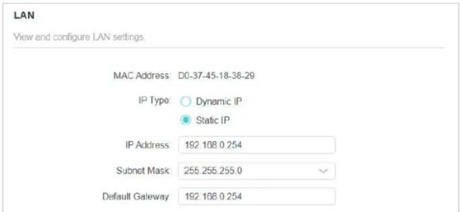
- Leave other parameters as the default settings.
- Click SAVE.
Tip:
After setting a static IP address, you can use the new IP address to log into the web management page besides http://tplinkap.net.
7.2. Specify DHCP Server Settings
By default, the DHCP (Dynamic Host Configuration Protocol) server works in Auto mode to avoid IP conflict. It will automatically assign IP addresses to clients from its IP address pool only when the DHCP server of the main router/AP is disabled.
You can change the DHCP server settings if necessary, and you can reserve LAN IP addresses for specified client devices.
Note:
If you disable the DHCP server and there is no other DHCP server within your LAN, you have to configure the IP address for each client manually.
- Visit http://tplinkap.net, and log in with the password you set for the access point.
- Go to Internet > DHCP Server.
• To specify the IP address range that the access point assigns:
- Turn on DHCP Server.
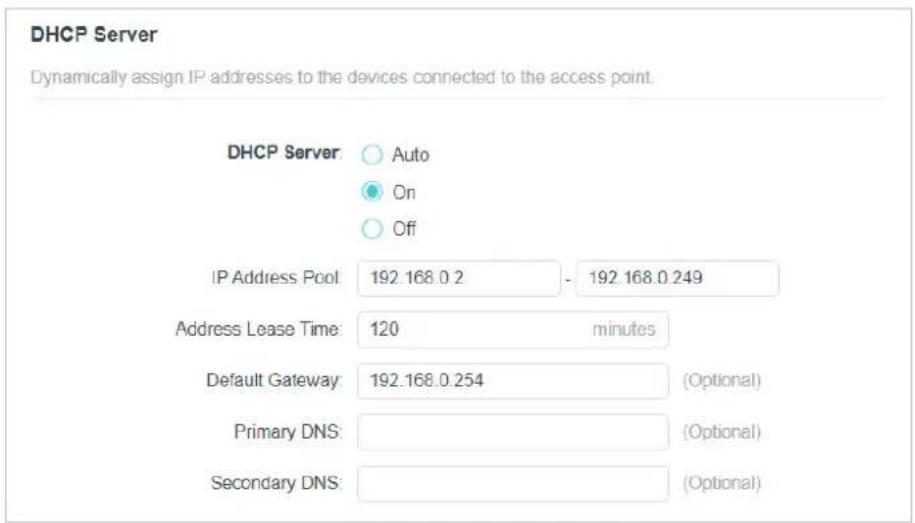
- Enter the starting and ending IP addresses of the IP Address Pool.
- Leave other parameters as the default settings.
- Click SAVE.
• To reserve an IP address for a specified client device:
The DHCP server of the access point works when it is turned on, or when it is in Auto mode with the DHCP server of the main router/AP disabled. When it is working, you can view the DHCP clients and reserve IP addresses for them.
- In the Address Reservation section, click Add.
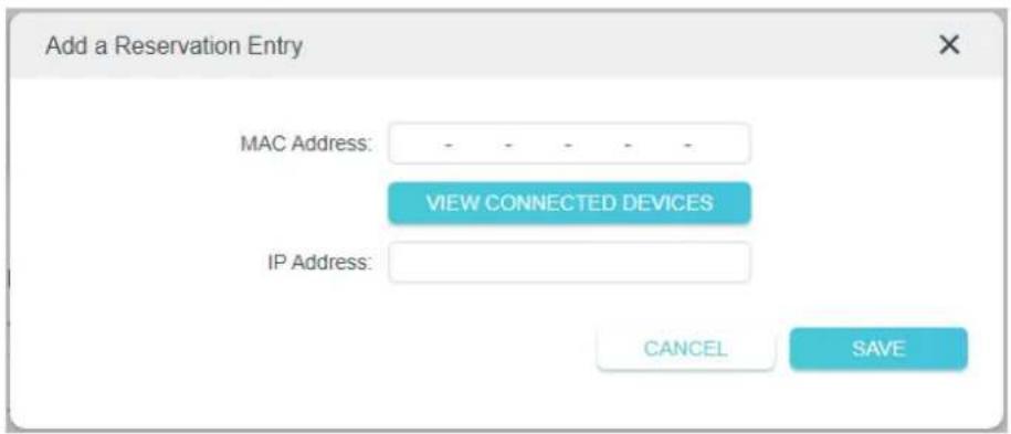
- Click VIEW CONNECTED DEVICES and select the device you want to reserve an IP for. The MAC Address will be automatically filled in. You can also enter the MAC address of the client device manually.
- Enter the IP address to reserve for the client device.
- Click SAVE.
Manage Your Access Point
This chapter will show you how to configure and manage your access point.
It contains the following sections:
- Set the System Time and Language
- Control LEDs
- Configure the SNMP Agent
- Configure the Ping Watchdog
- Update the Firmware
- Backup and Restore Configuration Settings
- Reboot the Access Point
- Change the Login Password
- Password Recovery
- Local Management • Test the Network Connectivity
- System Log
8. 1. Set the System Time and Language
System time is the time displayed while the access point is running. The system time you configure here will be used for other time-based functions like Reboot Schedule. You can choose the way to obtain the system time as needed.
System language is the language displayed when you log into the access point. You can change the system language as needed.
- Visit http://tplinkap.net, and log in with the password you set for the access point.
- Go to System > Time & Language.
- (Optional) Enable 24-Hour Time if you want to display the time in 24-hour format.
- Set the system time and language according to your needs.
• To set system language:
1) Select the language from the dropdown list.

2) Click SAVE.
• To get the system time from the internet:
1) In the Set Time field, select Get from Internet.

2) Select your local Time Zone from the drop-down list. 3) In the NTP Server I field, enter the IP address or domain name of your desired NTP Server.
4) (Optional) In the NTP Server II field, enter the IP address or domain name of the second NTP Server. 5) Click SAVE.
• To get the system time from the managing device:
1) In the Set Time field, select Get from Managing Device.
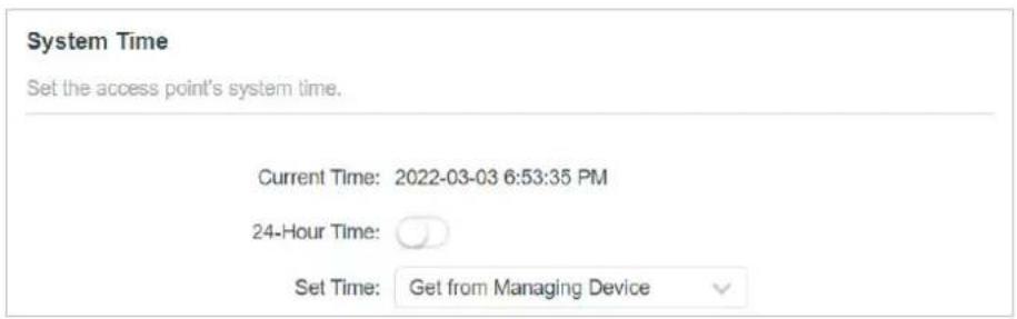
2) Click SAVE.
• To manually set the system time:
1) In the Set Time field, select Manually.
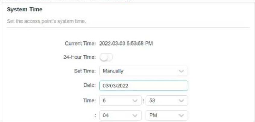
2) Set the current Date (In MM/DD/YYYY format). 3) Set the current Time (In HH/MM/SS format). 4) Click SAVE.
• To set up Daylight Saving Time:
1) Enable Daylight Saving Time.
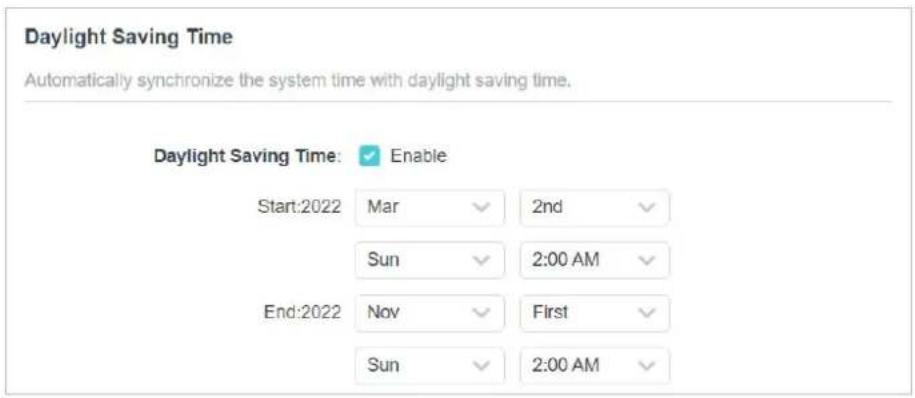
2) Select the correct Start date and time when daylight saving time starts at your local time zone. 3) Select the correct End date and time when daylight saving time ends at your local time zone. 4) Click SAVE.
8.2. Control LEDs
The LEDs of access point indicate its activities and status. You can turn off the LEDs when you don't need them.
- Visit http://tplinkap.net, and log in with the password you set for the access point.
- Go to System > LED Control.
- Turn off the LEDs when you don't need them.
- If you want to turn off LEDs immediately, turn off LED Status.

- If you want to turn off LEDs during a specific time period, follow the steps below:
1) Enable LED Status and Night Mode.
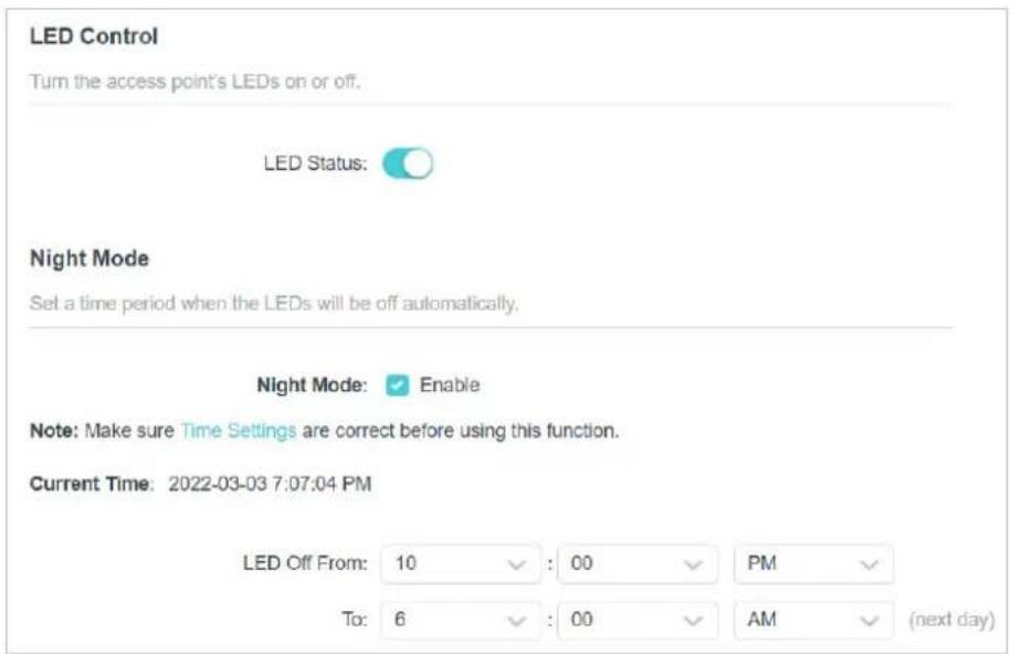
2) Specify the LED Off Time as needed, and the LEDs will be off during the period.
- Click SAVE.
8.3. Configure the SNMP Agent
SNMP (Simple Network Management Protocol) is a popular network monitoring and management protocol. You can configure the SNMP agent to communicate with your network monitoring tool or network management system.
- Visit http://tplinkap.net, and log in with the password you set for the access point.
- Go to System > SNMP.
- Enable SNMP Agent.
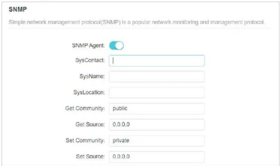
- Configure the SNMP agent according to your actual network requirement.
- SysContact – Enter the contact email address of the node to be managed.
- SysName – Set a user-defined name for the node to be managed.
- SysLocation – Enter the physical location of the node to be managed.
- Get Community – Enter the community name that allows read-only access to the device's SNMP information. The community name is considered as a group password. The default setting is public.
- Get Source – Enter the IP address or subnet that management systems can read information from this 'get' community.
Note: A restricted source can be a specific IP address (e.g. 10.10.10.1), or a subnet - represented as IP/BITS (e.g. 10.10.10.0/24). If 0.0.0.0 is specified as the IP address, the agent will accept all requests under the corresponding community name.
- Set Community – Enter the community name that allows read/write access to the device's SNMP information. The community name can be considered as a group password. The default setting is private.
- Set Source – Enter the IP address or subnet that management systems can read and write to this 'set' community.
Note: A restricted source can be a specific IP address (e.g. 10.10.10.1), or a subnet - represented as IP/BITS (e.g. 10.10.10.0/24). If 0.0.0.0 is specified as the IP address, the agent will accept all requests under the corresponding community name.
- Click SAVE.
8.4. Configure the Ping Watchdog
Ping Watchdog allows the access point to continuously ping a specific remote host for connection status using a user-defined IP address (or an internet gateway). If it is unable to ping the target IP address under the user-defined constraints, the device will automatically reboot.
- Visit http://tplinkap.net, and log in with the password you set for the access point.
- Go to System > Ping Watchdog.
- Enable Ping Watchdog.
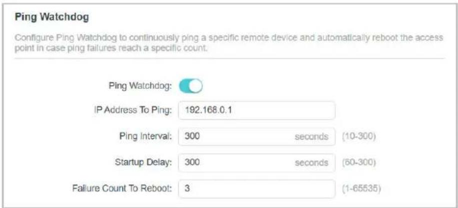
- In the IP Address To Ping field, enter the IP address of the target host that you want to send ping packets to.
- In the Ping Interval field, enter the time interval between two continuous ping packets.
- In the Startup Delay field, enter the time delay before the first ping packet is sent out when the device is restarted.
- In the Fail Count To Reboot field, enter a number of ping count(s) that the device can send continuously. If ping failures reach the value, the device will restart automatically.
- Click SAVE.
8.5. Update the Firmware
TP-Link is committed to improving product features, giving you a better network experience.
We will inform you through the web management page if there's any new firmware available for your access point. Also, the latest firmware will be released at the TP-Link official website www.tp-link.com, and you can download it from the Support page for free.
Note:
- Make sure the latest firmware file matches the hardware version (as shown in the download section of the Support page).
- Make sure that you have a stable connection between the access point and your computer. Wired connection is recommended.
- Back up your access point's configurations before firmware update.
- Do NOT turn off the access point during the firmware update.
8.5.1. Auto Update
- Visit http://tplinkap.net, and log in with the password you set for the access point.
- Go to System > Firmware Update.
- Enable Auto Update.
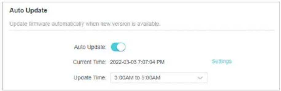
- Specify the Update Time and save the settings.
When a new version is available, the access point will update the firmware automatically at the specified time.
8.5.2. Online Update
- Visit http://tplinkap.net, and log in with the password you set for the access point.
- Go to System > Firmware Update. Tip: When new firmware is available for your access point, the update icon will display in the top-right corner of the web page. You can click the icon to go to the Firmware Update page.
- Focus on the Online Update section, click CHECK FOR UPDATES to see whether new firmware is available.
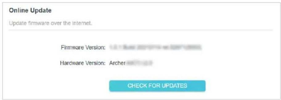
- Click UPDATE if there is new firmware.
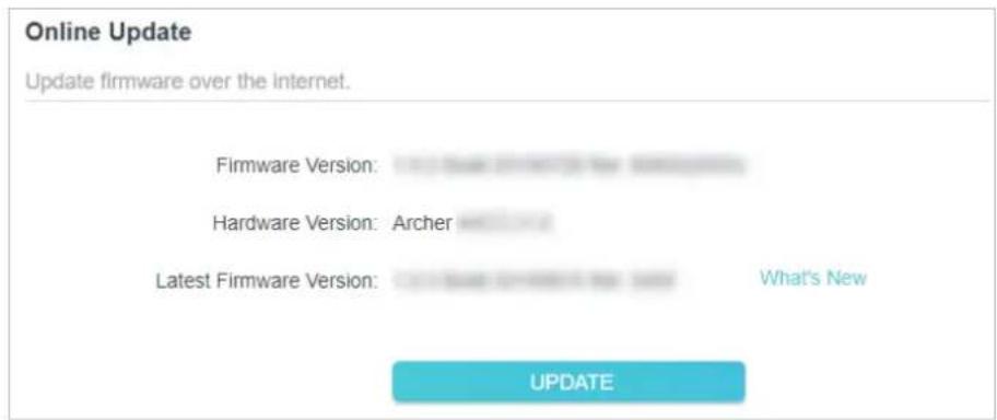
- Wait a few minutes for the update and reboot to complete.
8.5.3. Local Update
- Download the latest firmware file for the access point from www.tp-link.com.
- Visit http://tplinkap.net, and log in with the password you set for the access point.
- Go to System > Firmware Update.
- Focus on the Local Update section, click BROWSE to locate the downloaded new firmware file, and click UPDATE.
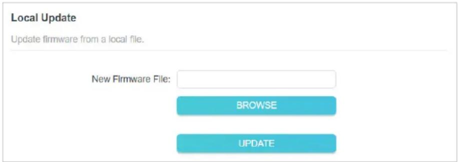
- Wait a few minutes for the update and reboot to complete.
Note: If you fail to update the firmware for the access point, please contact our Technical Support.
8. 6. Backup and Restore Configuration Settings
The configuration settings are stored as a configuration file in the access point. You can back up the configuration file to your computer for future use and restore the access point to previous settings from the backup file when needed. Moreover, if necessary, you can erase the current settings and reset the access point to its factory settings.
- Visit http://tplinkap.net, and log in with the password you set for the access point.
- Go to System > Backup & Restore.
- To back up configuration settings
Click BACK UP to save a copy of the current settings to your local computer. A '.bin' file of the current settings will be stored on your computer.

- To restore configuration settings
1) Click BROWSE to locate the backup configuration file stored on your computer, and click RESTORE.

2) Wait a few minutes for the restore and reboot.
Note: During the restore process, do not power off or reset the access point.
- To reset the access point except your login password and cloud account information:
1) In the Factory Default Restore section, click RESTORE.
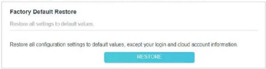
2) Wait a few minutes for the resetting and rebooting.
Note:
- During the resetting process, do not turn off the access point.
- After reset, you can still use the current login password or the TP-Link ID to log in to the web management page.
- To reset the access point to its factory settings:
1) In the Factory Default Restore section, click FACTORY RESTORE.
Restore all the configuration settings to their default values.
FACTORY RESTORE
2) Wait a few minutes for the resetting and rebooting.
Note:
- During the resetting process, do not turn off or reset the access point. • We strongly recommend you back up the current configuration settings before resetting the access point.
8.7. Reboot the Access Point
Rebooting helps clean cache and enhance running performance of the access point. You can reboot the access point immediately or schedule it to reboot periodically.
- Visit http://tplinkap.net, and log in with the password you set for the access point.
2. Go to System > Reboot.
• To reboot the access point immediately:
Click REBOOT.

• To schedule the access point to reboot periodically:
1) Enable Reboot Schedule.
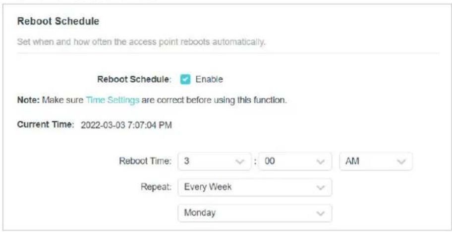
2) Set the Reboot Time and Repeat time. 3) Click SAVE. The access point will reboot periodically as scheduled.
8.8. Change the Login Password
The account management feature allows you to change your login password of the web management page.
- Visit http://tplinkap.net, and log in with the password you set for the access point.
- Go to System > Administration.
![Change Password Change the access point's local management password. Old Password: [blank] New Password: [blank] Confirm New Password: [blank]](/content/2026/06/1396708/images/8df7046540b8a43df48c07bb750609a1d2336f62972a09cb0d7acc5284b9dc3c.jpg)
- Enter the old password, and then enter a new password twice (both case-sensitive).
- Click SAVE and use the new password for future logins.
8.9. Password Recovery
This feature allows you to recover the login password you set for your access point in case you forget it.
- Visit http://tplinkap.net, and log in with the password you set for the access point.
- Go to System > Administration and focus on the Password Recovery section.
- Enable Password Recovery.
![Password Recovery Reset local management password via preset questions and answers. Password Recovery: [x] Enable From: To: SMTP Server: Authentication: [x] Enable Username: Password: [x]](/content/2026/06/1396708/images/857d1f7246b4f5dfff4af81cd204b7a281ee71c7d3a52d426f40bf5a75db60d0.jpg)
- Specify a mailbox (From) for sending the recovery letter and enter its SMTP Server address.
- Specify a mailbox (To) for receiving the recovery letter.
- If the mailbox (From) to send the recovery letter requires encryption, tick the Enable box of Authentication and enter its username and password.
Tips:
- SMTP server is available for users in most webmail systems. For example, the SMTP server address of Gmail is smtp.gmail.com.
- Generally, Authentication should be enabled if the login of the mailbox requires username and password.
7. Click SAVE.
To recover the login password, visit http://tplinkap.net, click Forgot Password? on the login page and follow the instructions to set a new password.
8. 10. Local Management
This feature allows you to limit the number of client devices on your LAN from accessing the access point by using the MAC address-based authentication.
- Visit http://tplinkap.net, and log in with the password you set for the access point.
- Go to System > Administration and focus on the Local Management section.
- Access the access point via HTTPS and HTTP:
Tick the Enable box of Local Management via HTTPS to access the access point via HTTPS and HTTP, or keep it disabled to access the access point only via HTTP.
![Local Management Access and manage the access point from local network devices. Local Management via HTTPS: [x] Enable Local Managers: All Devices](/content/2026/06/1396708/images/e5c60ccc7816546121044fd33f5fb52f77781bf0383a16a7a1088f51a1805c90.jpg)
- Allow all LAN connected devices to manage the access point:
Select All Devices for Local Managers.
![Local Management Access and manage the access point from local network devices. Local Management via HTTPS: [x] Enable Local Managers: All Devices](/content/2026/06/1396708/images/b4f93c441530a1ecd26051cf892e7f430e7ec132dd58d38f1a10819a9744ee83.jpg)
- Allow specific devices to manage the access point:
- Select Specified Devices for Local Managers and click SAVE.
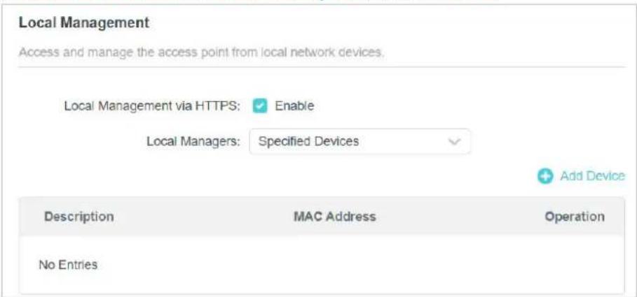
- Click Add Device.

- Click VIEW CONNECTED DEVICES and select the device to manage the access point from the devices list, or enter the MAC address of the device manually.
- Specify a Description for this entry.
- Click SAVE.
8. 11. Test the Network Connectivity
Diagnostics is used to test the connectivity between the access point and the host or other network devices.
Ping is used to test the connectivity between the access point and the tested host, and measure the round-trip time.
Traceroute is used to display the route (path) your access point has passed to reach the tested host, and measure transit delays of packets across an Internet Protocol network
- Visit http://tplinkap.net, and log in with the password you set for the access point.
- Go to System > Diagnostics.
• To test the connectivity via Ping:
1) Choose Ping as the diagnostic tool.
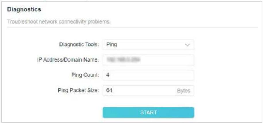
2) Enter the IP Address or Domain Name of the tested host. 3) Keep the default Ping Count and Ping Packet Size. 4) Click START to begin the diagnostics. The diagnostics result will be displayed.
PING 192.168.0.254 (192.168.0.254): 64 data bytes
Reply from 192.168.0.254: bytes=64 ttl=64 seq=1 time=0.361 ms
Reply from 192.168.0.254: bytes=64 ttl=64 seq=2 time=0.356 ms
Reply from 192.168.0.254: bytes=64 ttl=64 seq=3 time=0.378 ms
Reply from 192.168.0.254: bytes=64 ttl=64 seq=4 time=0.355 ms
— Ping Statistic "192.168.0.254" —
Packets: Sent=4, Received=4, Lost=0 (0.00% loss)
Round-trip min/avg/max = 0.355/0.362/0.378 ms
ping is stopped.
• To test the connectivity via Traceroute:
1) Choose Traceroute as the diagnostic tool.
Diagnostics
Troubleshoot network connectivity problems.
Diagnostic Tools:
Traceroute

IP Address/Domain Name:

Traceroute Max TTL:
5
START
2) Enter the IP Address or Domain Name of the tested host. 3) Keep the default Traceroute Max TTL. 4) Click START to begin the diagnostics. The diagnostics result will be displayed.
traceroute to 192.168.0.254, 5 hops max, 38 byte packets
1 tplinkap.net (192.168.0.254) 0.040 ms 0.033 ms 0.018 ms
Trace Complete.
traceroute is stopped.
8. 12. System Log
When the access point does not work normally, you can save the system log and send it to the technical support for troubleshooting.
• To save the system log locally:
- Visit http://tplinkap.net, and log in with the password you set for the access point.
- Go to System > System Log.
- Choose the type and level of the system logs as needed.
![System Log View a detailed record of system activities. Current Time: 2021-12-24 5:10:34 PM Log Type: All Search Refresh Clear All 2021-12-24 17.10.04 DHCP INFO [7336] send discover with ip 0.0.0.0 and flags 80 2021-12-24 17.09.34 DHCP INFO [7336] send discover with ip 0.0.0.0 and flags 0](/content/2026/06/1396708/images/e521e024477a05e18643023d0813a70693cd2827fe5131070dda6bd9adf8178f.jpg)
- In the Save Log section, click SAVE TO LOCAL to save the system logs to a local disk.

- To send the system log to a mailbox at a fixed time:
For example, I want to check my access point's working status at a fixed time every day, however, it's too troublesome to log in to the web management page every time I want to go checking. It would be great if the system logs could be sent to my mailbox at 8 a.m. every day.
- Visit http://tplinkap.net, and log in with the password you set for the access point.
- Go to System > System Log.
- In the Save Log section, click MAIL LOG.
- Enter the information required:
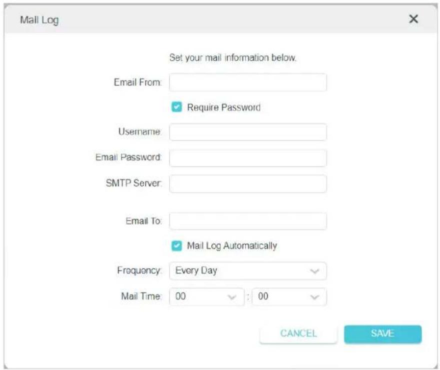
1) Email From: Enter the email address used for sending the system log. 2) Select Require Password.
Tips: Generally, Require Password should be selected if the login of the mailbox requires username and password.
3) Username: Enter the user name to log in to the sender's email address. 4) Email Password: Enter the password to log in to the sender's email address. 5) SMTP Server: Enter the SMTP server address.
Tips: SMTP server is available for users in most webmail systems. For example, the SMTP server address of Hotmail is smtp-mail.outlook.com. 6) Email To: Enter the recipient's email address, which can be the same as or different from the sender's email address. 7) Select Mail Log Automatically.
Tips: The access point will send the system log to the designated email address if this option is enabled.
8) Frequency: This determines how often the recipient will receive the system log. 9) Mail Time: Set the time when the recipient will receive the system log.
5. Click SAVE.
FAQ
Q1. How do I restore the access point to its factory default settings?
With the access point powered on, use a pin to press and hold the RESET button until the Power LED blinks, then release the button.
Note: Resetting the access point will clear all previous configurations, and the access point will reset to the default Access Point mode.
Q2. What should I do if I cannot access the web management page?
- If the computer has a static IP address, change its settings to obtain an IP address automatically.
- Verify that http://tplinkap.net or http://192.168.0.254 is correctly entered in the web browser.
- Use another web browser and try again.
- Reboot your access point and try again.
- Power off your host AP and enter http://tplinkap.net in the web browser to try again.
Q3. What should I do if I forget my wireless password?
The default wireless password is printed on the label of the access point. If the password has been altered, please connect your computer to the access point using an Ethernet cable and follow the steps below:
- Visit http://tplinkap.net, and log in with the password you set for the access point.
- Go to Wireless > Wireless Settings to retrieve or reset your wireless password.
Q4. What should I do if I forget my login password of the web management page?
- Refer to Q1 to reset the access point to its factory default settings.
- Visit http://tplinkap.net, and create a new login password.
Note: You'll need to reconfigure the access point to surf the internet once the access point is reset, and please mark down your new password for future use.
Q5. What should I do if my wireless is not stable?
This could be caused by interference. You can try the following methods:
- Log in to the web management page. Go to Wireless > Wireless Settings and change your wireless channel to a different one.
- Move the access point to a new location away from Bluetooth devices and other household electronics, such as cordless phones, microwaves, and baby monitors, to minimize signal interference.
Q6. What should I do to maximize my signal strength in Range Extender mode?
When choosing an ideal location to optimize wireless signal in Range Extender mode, please refer to the following recommendations.
- Halfway is the best way.
Generally, the ideal location for an access point is about halfway between your wireless router and your wireless clients, and make sure that the location you choose is within the range of the host router. If that is not possible, place it closer to your wireless router to ensure stable performance.
- Fewer obstacles ensure better performance.
Choose a location with fewer obstacles around that may block the signal between the access point and the host network. An open corridor or a spacious location is ideal.
• Less interference provides more stability.
Choose a location away from Bluetooth devices and other household electronics, such as cordless phones, microwaves, and baby monitors to minimize signal interference.
FCC compliance information statement

Product Name: AX3000 Gigabit Wi-Fi 6 Access Point
Model Number: TL-WA3001
| Component Name Model |
| I.T.E. Power Supply T480050-2B1 |
Responsible party:
TP-Link USA Corporation
Address: 10 Mauchly, Irvine, CA 92618
Website: http://www.tp-link.com/us/
Tel: +1 626 333 0234
This equipment has been tested and found to comply with the limits for a Class B digital device, pursuant to part 15 of the FCC Rules. These limits are designed to provide reasonable protection against harmful interference in a residential installation. This equipment generates, uses and can radiate radio frequency energy and, if not installed and used in accordance with the instructions, may cause harmful interference to radio communications. However, there is no guarantee that interference will not occur in a particular installation. If this equipment does cause harmful interference to radio or television reception, which can be determined by turning the equipment off and on, the user is encouraged to try to correct the interference by one or more of the following measures:
- Reorient or relocate the receiving antenna.
- Increase the separation between the equipment and receiver.
- Connect the equipment into an outlet on a circuit different from that to which the receiver is connected.
- Consult the dealer or an experienced radio/TV technician for help.
This device complies with part 15 of the FCC Rules. Operation is subject to the following two conditions:
- This device may not cause harmful interference.
- This device must accept any interference received, including interference that may cause undesired operation.
Any changes or modifications not expressly approved by the party responsible for compliance could void the user's authority to operate the equipment.
Note: The manufacturer is not responsible for any radio or TV interference caused by unauthorized modifications to this equipment. Such modifications could void the user's authority to operate the equipment.
FCC RF Radiation Exposure Statement
This equipment complies with FCC RF radiation exposure limits set forth for an uncontrolled environment. This device and its antenna must not be co-located or operating in conjunction with any other antenna or transmitter.
To comply with FCC RF exposure compliance requirements, this grant is applicable to only Mobile Configurations. The antennas used for this transmitter must be installed to provide a separation distance of at least 20 cm from all persons and must not be co-located or operating in conjunction with any other antenna or transmitter.
FCC compliance information statement

Product Name: I.T.E. Power Supply
Model Number: T480050-2B1
Responsible party:
TP-Link USA Corporation
Address: 10 Mauchly, Irvine, CA 92618
Website: http://www.tp-link.com/us/
Tel: +1 626 333 0234
This equipment has been tested and found to comply with the limits for a Class B digital device, pursuant to part 15 of the FCC Rules. These limits are designed to provide reasonable protection against harmful interference in a residential installation. This equipment generates, uses and can radiate radio frequency energy and, if not installed and used in accordance with the instructions, may cause harmful interference to radio communications. However, there is no guarantee that interference will not occur in a particular installation. If this equipment does cause harmful interference to radio or television reception, which can be determined by turning the equipment off and on, the user is encouraged to try to correct the interference by one or more of the following measures:
- Reorient or relocate the receiving antenna.
- Increase the separation between the equipment and receiver.
- Connect the equipment into an outlet on a circuit different from that to which the receiver is connected.
- Consult the dealer or an experienced radio/TV technician for help.
This device complies with part 15 of the FCC Rules. Operation is subject to the following two conditions:
- This device may not cause harmful interference.
- This device must accept any interference received, including interference that may cause undesired operation.
Any changes or modifications not expressly approved by the party responsible for compliance could void the user's authority to operate the equipment.
We, TP-Link USA Corporation, have determined that the equipment shown above complies with the applicable technical standards, FCC part 15. No unauthorized change is made in the equipment and the equipment is properly maintained and operated.
Issue Date: 2022-03-25
CE Mark Warning
CE
This is a class B product. In a domestic environment, this product may cause radio interference, in which case the user may be required to take adequate measures.
OPERATING FREQUENCY (the maximum transmitted power)
2400 MHz -2483.5 MHz (20dBm)
5150 MHz -5250 MHz (23dBm)
5250 MHz -5350 MHz (23dBm)
5470 MHz -5725 MHz (30dBm)
EU Declaration of Conformity
TP-Link hereby declares that the device is in compliance with the essential requirements and other relevant provisions of directives 2014/53/EU, 2009/125/EC, 2011/65/EU and (EU)2015/863.
The original EU Declaration of Conformity may be found at
https://www.tp-link.com/en/support/ce/
RF Exposure Information
This device meets the EU requirements (2014/53/EU Article 3.1a) on the limitation of exposure of the general public to electromagnetic fields by way of health protection.
The device complies with RF specifications when the device used at 20 cm from your body.
National Restrictions
Attention: This device may only be used indoors in all EU member states, EFTA countries and Northern Ireland.
 | AT | BE | BG | CH | CY | CZ | DE | DK | ||
| EE | EL | ES | FI | FR | HR | HU | IE | |||
| IS | IT | LI | LT | LU | LV | MT | NL | |||
| NO | PL | PT | RO | SE | SI | SK | UK(NI) | |||
UKCA Mark
UK CA
UK Declaration of Conformity
TP-Link hereby declares that the device is in compliance with the essential requirements and other relevant provisions of the Radio Equipment Regulations 2017.
The original UK Declaration of Conformity may be found at
https://www.tp-link.com/support/ukca
National Restrictions
Attention: This device may only be used indoors in Great Britain.

Canadian Compliance Statement
This device contains licence-exempt transmitter(s)/receiver(s) that comply with Innovation, Science and Economic Development Canada's licence-exempt RSS(s). Operation is subject to the following two conditions:
- This device may not cause interference.
- This device must accept any interference, including interference that may cause undesired operation of the device.
The device for operation in the band 5150–5250 MHz is only for indoor use to reduce the potential for harmful interference to co-channel mobile satellite systems.
DFS (Dynamic Frequency Selection) products that operate in the bands 5250-5350 MHz, 5470-5600 MHz, and 5650-5725 MHz.
Warning:
Radiation Exposure Statement:
This equipment complies with IC radiation exposure limits set forth for an uncontrolled environment. This equipment should be installed and operated with a minimum distance of 20 cm between the radiator and your body.
Industry Canada Statement
CAN ICES-3 (B)/NMB-3(B)
Korea Warning Statements:
| 設備名稱: AX3000 Gigabit Wi-Fi 6 Access Point 型號(型式): TL-WA3001Equipment name Type designation (Type) | ||||||
| 單元Unit | 限用物質及其化學符號Restricted substances and its chemical symbols | |||||
| 鉛Lead(Pb) | 汞Mercury(Hg) | 鎘Cadmium(Cd) | 六價鉻Hexavalent chromium( Cr+6 ) | 多溴聯苯Polybrominated biphenyls(PBB) | 多溴二苯醚Polybrominated diphenyl ethers(PBDE) | |
| PCB | ○ | ○ ○ ○ | ○ ○ | |||
| 外殼 | ○ | ○ ○ ○ | ○ ○ | |||
| 電源供應器 | - | ○ ○ | ○ ○ ○ | |||
| 天線 | ○ | ○ ○ ○ | ○ ○ | |||
| 備考1. “超出0.1 wt %”及“超出0.01 wt %”係指限用物質之百分比含量超出百分比含量基準值Note 1: “Exceeding 0.1 wt %” and “exceeding 0.01 wt %” indicate that the percentage content of the restricted substance exceeds the reference percentage value of presence condition.備考2. “○”係指該項限用物質之百分比含量未超出百分比含量基準值。Note 2: “○” indicates that the percentage content of the restricted substance does not exceed the percentage of reference value of presence.備考3. “—”係指該項限用物質為排除項目。Note 3: The “—” indicates that the restricted substance corresponds to the exemption. | ||||||

- Keep the device away from water, fire, humidity, or hot environments.
- Do not attempt to disassemble, repair, or modify the device. If you need service, please contact us.
- Do not use a damaged charger or USB cable to charge the device.
- Do not use any other chargers than those recommended.
- Do not use the device where wireless devices are not allowed.
- The adapter shall be installed near the equipment and shall be easily accessible.
- Use only power supplies provided by the manufacturer and in the original packaging of this product. If you have any questions, please don't hesitate to contact us.
- Operating Temperature: 0°C 40°C (32°F \~ 104°F)
- This product uses radios and other components that emit electromagnetic fields. Electromagnetic fields and magnets may interfere with pacemakers and other implanted medical devices. Always keep the product and its power adapter more than 15 cm (6 inches) away from any pacemakers or other implanted medical devices. If you suspect your product is interfering with your pacemaker or any other implanted medical device, turn off your product and consult your physician for information specific to your medical device.
Please read and follow the above safety information when operating the device. We cannot guarantee that no accidents or damage will occur due to improper use of the device. Please use this product with care and operate at your own risk.
Explanations of the symbols on the product label
| Symbol Explanation | |
 | DC voltage |
 | AC voltage |
 | Class II equipment |
 | Polarity of output terminals |
 | Energy efficiency Marking |
 | Indoor use only |
 | Caution |
 | Operator's manual |
 | RECYCLINGThis product bears the selective sorting symbol for Waste electrical and electronic equipment (WEEE). This means that this product must be handled pursuant to European directive 2012/19/EU in order to be recycled or dismantled to minimize its impact on the environment.User has the choice to give his product to a competent recycling organization or to the retailer when he buys a new electrical or electronic equipment. |
- CONTENTS
- ABOUT THIS GUIDE
- CHAPTER 1. GET TO KNOW ABOUT YOUR ACCESS POINT
- CHAPTER 2. SET UP INTERNET CONNECTION
- CHAPTER 3. TP-LINK CLOUD SERVICE (FOR ACCESS POINT MODE)
- CHAPTER 4. WIRELESS SETTINGS
- CHAPTER 5. PORTAL (FOR ACCESS POINT/MULTI-SSID MODE)
- CHAPTER 6. ACCESS CONTROL
- CHAPTER 7. CUSTOMIZE NETWORK SETTINGS
- CHAPTER 8. MANAGE YOUR ACCESS POINT
- FAQ
- CONVENTIONS
- MORE INFO
- CHAPTER
- GET TO KNOW ABOUT YOUR ACCESS POINT
- PRODUCT OVERVIEW
- PANEL LAYOUT
- TOP VIEW
- BACK PANEL
- SET UP INTERNET CONNECTION
- POSITION YOUR ACCESS POINT
- NOTE
- SET UP YOUR ACCESS POINT
- ACCESS POINT MODE (DEFAULT)
- RANGE EXTENDER MODE
- CLIENT MODE
- MULTI-SSID MODE
- TIP
- TP-LINK CLOUD SERVICE
- (FOR ACCESS POINT MODE)
- REGISTER A TP-LINK ID
- CHANGE YOUR TP-LINK ID INFORMATION
- TO CHANGE YOUR PASSWORD
- MANAGE THE USER TP-LINK IDS
- ADD TP-LINK ID TO MANAGE THE ACCESS POINT
- REMOVE TP-LINK ID(S) FROM MANAGING THE ACCESS POINT
- MANAGE THE ACCESS POINT VIA THE TP-LINK TETHER APP
- WIRELESS SETTINGS
- SPECIFY WIRELESS SETTINGS
- ACCESS POINT MODE
- TO ENABLE OR DISABLE OFDMA
- TO ENABLE OR DISABLE TWT
- TO USE THE SMART CONNECT FUNCTION
- TO ENABLE OR DISABLE A WIRELESS BAND
- TO CHANGE THE WIRELESS NETWORK NAME (SSID) AND WIRELESS PASSWORD
- TO HIDE SSID
- CONNECT TO MAIN NETWORK
- WI-FI SCANNER
- CLICK SAVE
- USE WPS FOR WIRELESS CONNECTION (FOR ACCESS POINT/MULTI-SSID MODE)
- METHOD 2: USING THE BUTTON BELOW
- CHECK ADVANCED WIRELESS SETTINGS (FOR ACCESS POINT/MULTI-SSID MODE)
- MONITOR WIRELESS STATISTICS (FOR ACCESS POINT/MULTI-SSID MODE)
- MONITOR THE TRAFFIC THROUGHPUT (FOR ACCESS POINT/MULTI-SSID MODE)
- PORTAL
- ACCESS CONTROL
- TO BLOCK SPECIFIC DEVICES
- TO ALLOW SPECIFIC DEVICES
- DONE
- CUSTOMIZE NETWORK SETTINGS
- CHANGE THE LAN SETTINGS
- SPECIFY DHCP SERVER SETTINGS
- MANAGE YOUR ACCESS POINT
- SET THE SYSTEM TIME AND LANGUAGE
- CONTROL LEDS
- CONFIGURE THE SNMP AGENT
- CONFIGURE THE PING WATCHDOG
- UPDATE THE FIRMWARE
- AUTO UPDATE
- ONLINE UPDATE
- LOCAL UPDATE
- BACKUP AND RESTORE CONFIGURATION SETTINGS
- REBOOT THE ACCESS POINT
- GO TO SYSTEM > REBOOT
- CHANGE THE LOGIN PASSWORD
- PASSWORD RECOVERY
- LOCAL MANAGEMENT
- TEST THE NETWORK CONNECTIVITY
- TO TEST THE CONNECTIVITY VIA TRACEROUTE
- CHOOSE TRACEROUTE AS THE DIAGNOSTIC TOOL
- DIAGNOSTICS
- SYSTEM LOG
- TO SAVE THE SYSTEM LOG LOCALLY
- Q1. HOW DO I RESTORE THE ACCESS POINT TO ITS FACTORY DEFAULT SETTINGS
- Q2. WHAT SHOULD I DO IF I CANNOT ACCESS THE WEB MANAGEMENT PAGE
- Q3. WHAT SHOULD I DO IF I FORGET MY WIRELESS PASSWORD
- Q4. WHAT SHOULD I DO IF I FORGET MY LOGIN PASSWORD OF THE WEB MANAGEMENT PAGE
- Q5. WHAT SHOULD I DO IF MY WIRELESS IS NOT STABLE
- Q6. WHAT SHOULD I DO TO MAXIMIZE MY SIGNAL STRENGTH IN RANGE EXTENDER MODE
- FCC COMPLIANCE INFORMATION STATEMENT
- FCC RF RADIATION EXPOSURE STATEMENT
- CE MARK WARNING
- CE
- OPERATING FREQUENCY (THE MAXIMUM TRANSMITTED POWER)
- EU DECLARATION OF CONFORMITY
- RF EXPOSURE INFORMATION
- NATIONAL RESTRICTIONS
- UKCA MARK
- UK CA
- UK DECLARATION OF CONFORMITY
- CANADIAN COMPLIANCE STATEMENT
- WARNING
- RADIATION EXPOSURE STATEMENT
- INDUSTRY CANADA STATEMENT
- KOREA WARNING STATEMENTS
Brand : TP-LINK
Model : TL-WA3001
Category : Access Point