
MURELLE REVOLUTION 30 - Boiler SIME - Free user manual and instructions
Find the device manual for free MURELLE REVOLUTION 30 SIME in PDF.


| Product Type | Gas Boiler |
| Brand | SIME |
| Model | MURELLE REVOLUTION 30 |
| Energy Source | Natural Gas / Propane |
| Power Output | 30 kW |
| Efficiency (Condensing) | Up to 98% (on HCV) |
| Dimensions (HxWxD) | 800 x 440 x 350 mm |
| Weight | 35 kg |
| Flow Temperature Range | 30 - 80 °C |
| Domestic Hot Water (DHW) Output | 15 L/min at ΔT 30°C |
| Electrical Supply | 230 V / 50 Hz |
| Electrical Power Consumption | 150 W |
| IP Rating | IPX4 |
| NOx Class | Class 6 |
| Sealed Combustion Chamber | Yes (Room-Sealed) |
| Display | LCD with backlight |
| Main Functions | Central heating, domestic hot water, anti-legionella, summer/winter mode |
| Safety Devices | Flame detection, overheat protection, frost protection, pressure sensor |
| Maintenance Interval | Annual service recommended |
| Spare Parts Availability | At least 10 years after production |
| Warranty | 2 years (standard), up to 5 years upon registration |
Frequently Asked Questions - MURELLE REVOLUTION 30 SIME
User questions about MURELLE REVOLUTION 30 SIME
0 question about this device. Answer the ones you know or ask your own.
Ask a new question about this device
Download the instructions for your Boiler in PDF format for free! Find your manual MURELLE REVOLUTION 30 - SIME and take your electronic device back in hand. On this page are published all the documents necessary for the use of your device. MURELLE REVOLUTION 30 by SIME.
USER MANUAL MURELLE REVOLUTION 30 SIME
USER, INSTALLATION AND SERVICING INSTRUCTIONS
natural_image
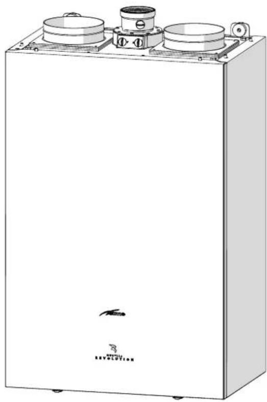
Technical line drawing of a white industrial machine with three circular components and mounting brackets (no text or symbols)
ENSURE THAT THESE INSTRUCTIONS ARE LEFT FOR THE USER AFTER COMPLETION OF THE BENCHMARK SECTION
PLEASE READ THE IMPORTANT NOTICE WITHIN THIS GUIDE REGARDING YOUR BOILER WARRANTY

WRAS WATER REGULATIONS ADVISORY SCHEME



It is compulsory to read the instructions.

Visit our website: www.sime.it

8510-22-0031
sime
BOILER DETAILS
please position here a sticker from installation pack
IMPORTANT NOTICE
For the first year all of our appliances are protected by our manufacturer's guarantee which covers both parts and labour.
As you would expect from Sime Ltd, it is our aim to provide our valued customers with the best in after sales and service.
To take advantage of any extended warranty offered, all you have to do is to adhere to these 3 simple conditions:
- The installation must be carried out to Manufacturers/Benchmark Standards by a Gas Safe Registered Engineer, and recorded in the installation manual.
• The appliance must be registered with both Sime Ltd and Gas Safe within 30 days of installation. - The appliance must be serviced every 12 months, within 30 days of the anniversary of the installation date, by either Sime Ltd or a Gas Safe registered engineer- ensuring that the Benchmark service record in the installation manual is completed.
Failure to comply with the above will result in only the 12 month warranty being offered. In the absence of any proof of purchase, the 12 month warranty period will commence from the date of manufacture of the boiler as shown on the appliance data plate.
SAFE HANDLING
This boiler may require 2 or more operatives to move it into its installation site, remove it from its packaging and during movement into its installation location. Manoeuvring the boiler may include the use of a sack truck and involve lifting pushing and pulling.
Caution should be exercised during these operations.
Operatives should be knowledgeable in handling techniques when performing these tasks and the following precautions should be considered:
- Grip the boiler at the base
- Be physically capable
- Use personal protective equipment as appropriate e.g. gloves, safety footwear.
During all manoeuvres and handling actions, every attempt should be made to ensure the following unless unavoidable and/or the weight is light.
- Keep back straight
- Avoid twisting at the waist
- Always grip with the palm of the hand
- Keep load as close to the body as possible
- Always use assistance
WARNING
Caution should be exercised when performing any work on this appliance.
Protective gloves and safety glasses are recommended.
- Avoid direct contact with sharp edges.
- Avoid contact with any hot surfaces.
NOTICE
Please be aware that due to the wet testing of the appliance, there may some residual water in the hydraulic circuit.
- Protect any surfaces, carpets or floorings.
- Use a suitable container to catch any water that escape when removing the protective caps from the connections.
All descriptions and illustrations provided in this manual have been carefully prepared but we reserve the right to make changes and improvements in our products that may affect the accuracy of the information contained in this manual.
Code Of Practice
For the installation, commissioning and servicing of domestic heating and hot water products
Benchmark places responsibilities on both manufacturers and installers.* The purpose is to ensure that customers** are provided with the correct equipment for their needs, that it is installed, commissioned and serviced in accordance with the manufacturer's instructions by competent persons and that it meets the requirements of the appropriate Building Regulations. Installers are required to carry out work in accordance with the following:

*The use of the word "installer" is not limited to installation itself and covers those carrying out installation, commissioning and/or servicing of heating and hot water products, or the use of supporting products (such as water treatment or test equipment).
**Customer includes householders, landlords and tenants.
© Heating and Hotwater Industry Council (HHIC)
Standards of Work
- Be competent and qualified to undertake the work required.
• Install, commission, service and use products in accordance with the manufacturer's instructions provided. - Ensure that where there is responsibility for design work, the installation is correctly sized and fit for purpose.
- Meet the requirements of the appropriate Building Regulations. Where this involves notifiable work be a member of a Competent Persons Scheme or confirm that the customer has notified Local Authority Building Control (LABC), prior to work commencing.
- Complete all relevant sections of the Benchmark Checklist/Service Record when carrying out commissioning or servicing of a product or system.
- Ensure that the product or system is left in a safe condition and, whenever possible, in good working order.
- Highlight to the customer any remedial or improvement work identified during the course of commissioning or servicing work.
- Refer to the manufacturer's helpline where assistance is needed.
• Report product faults and concerns to the manufacturer in a timely manner.
Customer Service
- Show the customer any identity card that is relevant to the work being carried out prior to commencement or on request.
- Give a full and clear explanation/demonstration of the product or system and its operation to the customer.
- Hand over the manufacturer's instructions, including the Benchmark Checklist, to the customer on completion of an installation.
- Obtain the customer's signature, on the Benchmark Checklist, to confirm satisfactory demonstration and receipt of manufacturer's instructions.
- Advise the customer that regular product servicing is needed, in line with manufacturers' recommendations, to ensure that safety and efficiency is maintained.
- Respond promptly to calls from a customer following completion of work, providing advice and assistance by phone and, if necessary, visiting the customer.
- Rectify any installation problems at no cost to the customer during the installer's guarantee period.
www.centralheating.co.uk
The Benchmark Scheme
Sime is a licensed member of the Benchmark Scheme which aims to improve the standards of installation and commissioning of domestic heating and hot water systems in the UK and to encourage regular servicing to optimise safety, efficiency and performance.
Benchmark is managed and promoted by the Heating and Hotwater Industry Council.
For more information visit www.centralheating.co.uk.
Please ensure that the installer has fully completed the Benchmark Checklist in the use and maintenance section of the installation instructions supplied with the product and that you have signed it to say that you have received a full and clear explanation of its operation.
The installer is legally required to complete a commissioning checklist as a means of complying with the appropriate Building Regulations (England and Wales).
All installations must be notified to Local Area Building Control either directly or through a Competent Persons Scheme.
A Building Regulations Compliance Certificate will then be issued to the customer who should, on receipt, write the Notification Number on the Benchmark Checklist.
This product should be serviced regularly to optimise its safety, efficiency and performance.
The service engineer should complete the relevant Service Record on the Benchmark Checklist after each service.
The Benchmark Checklist may be required in the event of any warranty work and as supporting documentation relating to home improvements in the optional documents section of the Home Information Pack.
Important Information
IT IS A STATUTORY REQUIREMENT THAT ALL GAS APPLIANCES ARE INSTALLED BY COMPETENT PERSONS, IN ACCORDANCE WITH THE GAS SAFETY (INSTALLATION AND USE) REGULATIONS (CURRENT EDITION). The manufacturer's instructions must not be taken as overriding any statutory requirements, and failure to comply with these regulations may lead to prosecution.
No modifications to the appliance should be made unless they are fully approved by the manufacturer.
GAS LEAKS: DO NOT OPERATE ANY ELECTRICAL SWITCH, OR USE A NAKED FLAME. TURN OFF THE GAS SUPPLY AND VENTILATE THE AREA BY OPENING DOORS AND WINDOWS CONTACT THE GAS EMERGENCY SERVICE ON 0800111999.

Please refer to commissioning instructions for filling in the checklist at the back of this installation guide.
Note: All Gas Safe registered installers carry a ID Card.
You can check your installer is Gas Safe Registered by calling 0800 408 5577
Please remember to carry out the following checks after installation. This will achieve complete customer satisfaction, and avoid unnecessary service calls. A charge will be made for a service visit where the fault is not due to a manufacturing defect.
- Has a correct by-pass been fitted and adjusted?
- Has the system and boiler been flushed?
- Is the system and boiler full of water, and the correct pressure showing on the pressure gauge?
- Is the Auto Air Vent open?
- Has the pump been rotated manually?
- Is the gas supply working pressure correct?
- Is the boiler wired correctly? (See installation manual).
- Has the D.H.W. flow rate been set to the customer requirements?
- Has the customer been fully advised on the correct use of the boiler, system and controls?
- Has the Benchmark Checklist in the use and maintenance section of this manual, been completed?

WARNINGS
- After having unpacked the boiler ensure that it is undamaged and complete including the valve pack, hanging bracket and template.
- The appliance must be used as intended. Sime Ltd declines all responsible for any injury or damage to persons, animals, or property as a result of improper installation, adjustment, maintenance or use.
- In the event of water leaks, disconnect the appliance from the mains power supply, close the water mains and seek help from a qualified engineer.
- If the refrigerant gas (which is colourless and odourless) leaks from the appliance, disconnect the unit from mains power, and open the windows and doors to ventilate the room. Make sure to install gas detectors as required by local safety regulations.
- Periodically check that the operating pressure of the water heating system when cold is 1-1.2 bar. If required, increase the pressure or seek help from a qualified engineer.
- If the appliance is not used for a long period of time, the following operations must be carried out:
-set the main isolation switch to "OFF"; -close the gas and water valves for the water heating system.
- To ensure continued efficient operation of the appliance it is recommended that it is serviced regularly, at least once a year. This is also a condition of the boiler warranty. It is the law that any service or repair is carried out by a Gas Safe Registered engineer. Services must be recorded in the maintenance section of this installation guide.
- The system's power connection is of the "Y" type, so the power cable may only be replaced by the manufacturer or the service department.
- The concentration of CO in combustion by-products must always comply with the installation regulations of the country where the appliance is installed.

WARNINGS
- It is recommended that all operators read this manual carefully in order to use the appliance in a safe and rational manner.
- This manual is an integral part of the appliance. It must therefore be kept for future reference and must always accompany the appliance.
- Installation and maintenance of this appliance must be carried out by a qualified company or by a professionally qualified technician in accordance with the instructions contained in the manual. Once the work is complete, the company or technician will issue a declaration of conformity with national and local technical standards and legislation in force in the country where the appliance will be used.
- Any repairs on the appliance must be carried out solely by professionally qualified personnel, using original spare parts only. Failure to comply with these instructions can jeopardise the appliance's safety and void the warranty with immediate effect.
- Fonderie SIME S.p.A. reserves the right to make improvements to its products at any time without prior notice, without compromising their essential characteristics. The graphic illustrations and/or images in this document may show optional accessories that vary according to the country in which the appliance is used.
- The installer must explain to the User the appliance's operation and the safety instructions. Moreover, the installer must hand the use and maintenance instructions to the User after completing the installation.

PROHIBITION
- To allow children under the age of 8 to use the appliance. The appliance can be used by children no younger than 8 years old, by people with physical or cognitive disabilities, and by people lacking experience or the necessary knowledge, provided that they are supervised or have been instructed on how to use the appliance safely and that they understand the risks associated with it.
- To allow children to play with the appliance.
- To allow unsupervised children to perform user maintenance and cleaning.
-
To use electrical devices or appliances such as switches, electrical appliances etc if you can smell gas. If this should happen:
-
open the doors and windows to ventilate the room;
-
turn the gas off at the meter;
-call the emergency service 0800 111999. -
To touch the appliance with bare feet or with any wet part of the body.
- To carry out any repair, maintenance or cleaning operation before having disconnected the appliance from the mains power by setting the main switch to "OFF", and closing the gas supply.
- To modify the safety or adjustment devices without authorization and instructions from the manufacturer.
- To modify or plug the condensate outlet (if present).

PROHIBITION
- To pull, detach or twist the electrical cables coming out of the appliance even if the appliance is disconnected from the mains power supply.
- To expose the boiler to atmospheric agents. These boilers can also be installed in partially covered areas, as per EN 15502, with a maximum ambient temperature of 60^ and a minimum ambient temperature of -5^ . It is generally advisable to install the boilers below weathered roofs, on the balcony or in a protected niche, to protect them from exposure to weathering agents (rain, hail and snow). All boilers provide a standard antifreeze function.
- To leave containers with flammable substances in the room where the appliance is installed.
- To dispose of the packaging material irresponsibly as it could be dangerous. Packaging must be disposed of as specified by the legislation in force in the country where the appliance will be used.
- Release the refrigerant gas since it is potentially hazardous to the environment and persons.
- To load the refrigerating circuits with a refrigerant other than the one indicated on the ID plate. Using a different refrigerant may cause serious damage to the compressor.
- To use oils other than those indicated in this manual. Using a different oil may cause serious damage to the compressor.
- To modify or intervene on sealed components.
LIST OF ABBREVIATIONS USED IN THE MANUAL
Below is a list of abbreviations that can be used in the diagrams in the manual.
| ABBREVIATION | DESCRIPTION |
| * | Optional |
| 0/10V | 0/10 V input |
| ACS | Domestic hot water |
| AIN | Inertial storage |
| AL | Power supply |
| ALIM | Power supply |
| APDC | Heat pump power supply |
| AR | Remote alarm |
| ARM | Cabinet |
| ASF | Flame signal amplifier |
| AUX | Auxiliary output |
| BK | Black |
| BL | Blue |
| BO | Tank |
| BR | Brown |
| BRU | Burner |
| C | Domestic hot water recirculation attachment |
| CAA | Boiler air inlet duct |
| CALDAIA | Boiler |
| CMI | Microprocessors controller |
| CN | Connector |
| COID | Hydraulic manifold / hydraulic disconnector |
| COMP | Compressor |
| COND | Capacitor |
| COS | Solar collector |
| CPDC | Heat pump controller |
| CR | Remote control / command |
| CRI | Heater consent |
| CSFU | Smoke outlet duct |
| CSFUC | Coaxial flue gas duct |
| CSFUS | Separate flue gas exhaust duct |
| CTP | Programmer timer-controlled thermostat |
| DA | Active dehumidifier |
| DAL | Alarm device |
| DF | Dirt separator |
| DP | Polyphosphate dosing unit |
| E | Domestic hot water inlet |
| E/I | Summer / Winter switch |
| EA | Electrode on |
| EAR | Ignition / detection electrode |
| EL | Electrical connections and External controls |
| EMC | Boiler emergency activation at boiler TA2 |
| ER | Flame detection electrode |
| EV | Solenoid valve |
| EVAT | High-temperature solenoid valve |
| EVC | Fuel solenoid valve |
| EVCA | Automatic charging solenoid valve |
| EVD | Diverter solenoid valve |
| EVG | Gas solenoid valve |
| EVMS | DHW mix solenoid valve |
| EVZ | Zone solenoid valve |
| ABBREVIATION | DESCRIPTION |
| EXP | Expansion card |
| FA | Noise filter |
| FAST | Combined boiler (instantaneous DHW + technical water) |
| FE | Ferrite ring |
| FL | Flow switch |
| FLM | Дебитомер |
| FR | Line filter |
| FU | Fuse |
| FV | Photovoltaic |
| FY | Y Filter |
| G | Gas supply |
| GI | Expansion joint |
| GN | Green |
| GR | Grey |
| GS | Solar unit |
| GSM | Phone dialler |
| HiT2 | Cascade manager |
| HP | HP high pressure switch |
| HYBW | Hybrid Wall |
| I | Inductance |
| ID | Digital input configurable |
| IDFV | Photovoltaic digital input |
| IG | Main switch |
| IMP | System |
| JP | Jumper |
| KA | Relè |
| KAP | Circulator relay |
| KARA | DHW heating element relay |
| KARI | System heating element relay |
| KAV | Fan relay |
| KIT HYBRID | Hybrid kit |
| L | Line / Live |
| LBL | Light Blue |
| LGR | Refrigerant gas line |
| LP | HP low pressure switch |
| LR | Refrigerant fluid line |
| M | System flow |
| MA | Pressure gauge |
| MB | Hot water tank delivery |
| MCB | Magneto-thermal switch |
| MEQ | Terminals external to panel |
| MIQ | Terminal block inside the panel |
| MMI | Control interface |
| MO | Generic motor |
| MODBUS | Connections for MOD-BUS input |
| MPDC | Delivery from heat pump |
| MR | Terminal block |
| MSOL | Solar delivery |
| MV | Fan motor |
| MVG | Gas valve modulator |
| N | Neutral |
| ABBREVIATION | DESCRIPTION |
| OP | Mechanical timer |
| OR | Orange |
| OT | OpenTherm communication protocol |
| OV | Thermostatic diverter mixer valve |
| P | Circulator |
| PAC | Water pressure switch |
| PAR | Air pressure switch |
| PB | Calorifier circulator |
| PCP | Main control panel |
| PDC | Heat pump |
| PE | Earth Protection |
| PFU | Smoke pressure switch |
| PGM | Gas low pressure switch (methane / LPG) |
| PI | System circulator pump |
| PIAT | High-temperature circulator |
| PIBT | Low-temperature system circulator pump |
| PK | Pink |
| PM | System modulating circulator |
| Pmax | High pressure switch |
| Pmin | Low pressure switch |
| PR | Re-starter circulating pump |
| PRC | Recirculation circulator |
| PRIACS | Domestic hot water instantaneous preparer |
| PS | Domestic hot water circulator |
| PSAUX | Auxiliary DHW storage tank circulating pump |
| PSOL | Solar system circulator |
| PSRO | Burner remote unlock button |
| PUFFER | Puffer |
| PUFW | Puffer Wall |
| QE | Electrical panel |
| QE MEM | MEM electrical panel |
| R | System return |
| RB | Hot water tank return |
| RC | Recirculation |
| RCO | Fuel return |
| RD | Red |
| RDT | Radiator |
| RE | Electrical resistance |
| REACS | DHW heating element |
| REAG | Anti-freeze heating element |
| REimp | System heating element |
| RGPDC | Heat pump regulator |
| RGSOL | Solar controller |
| RISCO | Fuel heater |
| RPDC | Return to heat pump |
| RPSOL | Solar circulator return |
| RRF | Radio-frequency receiver |
| RSOL | Solar return |
| S | Generic temperature sensor |
| SA | Voltage indicator light |
| SAE | External air intake probe |
| SAUX | Auxiliary sensor |
| SB | Calorifier drainage outlet |
| SBB | Burner lock-out indicator light |
| SBL | Calorifier sensor (DHW) |
| SBLA | Storage Tank High Sensor ACS |
| SBLAUX | Auxiliary hot water storage tank sensor |
| SBLB | Storage Tank Low Sensor ACS |
| SBS | Solar hot water tank sensor |
| SBT | Low temperature sensor |
| SC | Condensate outlet |
| SCC | Boiler board |
| SCI | Hydronic board |
| SCM | Control board |
| SCMM | Master control board |
| SCV | Fan control probe |
| SE | Outdoor air temperature probe |
| SEP | Pressure sensor |
| SFU | Exhaust sensor |
| SI | System drainage outlet |
| SIA | Air inlet probe |
| SID | Hydraulic separator |
| SL | Level sensor |
| SLB | Battery liquid sensor |
| SM | Delivery sensor |
| SMC | Boiler delivery sensor |
| SMCA | Cascade delivery probe |
| SMG | Generators delivery probe |
| SMI | System delivery sensor |
| SP | Plate heat exchanger |
| SPAC | Water pressure switch activation indicator light |
| SPS | Domestic hot water preheating sensor |
| SPU | Puffer probe (technical water - no DHW) |
| SR | Return sensor (SR) |
| SRC | Boiler return probe |
| SRE | Relay board |
| SRE2 | 2-relay board |
| SRI | System return probe |
| SRRF | Radiofrequency sensor |
| SS | Domestic hot water sensor |
| SSC | Compressor discharge sensor |
| SSIC | Boiler inlet DHW probe |
| SSOL | Solar manifold probe |
| ABBREVIATION | DESCRIPTION |
| SSP | Plate heat exchanger liquid temperature probe |
| STC | Condenser temperature sensor |
| SUA | Water outlet sensor |
| SVB | Tank relief valve |
| SVI | System relief valve drainage outlet |
| SVS | Safety valve outlet |
| T | Thermometer |
| TA | Room thermostat |
| TA230 | Room thermostat 230 V |
| TAC | Heating room thermostat |
| TACS | Domestic water thermostat |
| TAF | Cooling room thermostat |
| TAZ | Zone ambient thermostat |
| TBL | Hot water tank thermostat |
| TC | Boiler thermostat |
| TFU | Smoke thermostat |
| TFUS | Thermal fuse |
| TL | Temperature-limit thermostat |
| TMIN | Minimum-temperature thermostat |
| TPAC | Water pressure transducer |
| TR | Heating thermostat |
| TRA | Ignition transformer |
| TS | Safety thermostat |
| U | Domestic hot water output |
| UE | External unit |
| UG | Nozzle |
| UI | Internal unit |
| UR | Humidistat |
| V | Fan |
| V3W | 3-way valves |
| V4W | 4-way valve |
| V5W | 5-way valve |
| VBP | By-pass valve |
| VC | Automatic filling valve |
| VCC | Fan coil unit (heating only) |
| VCF | Fan coil unit (heating/ cooling) |
| VD | Diverter valve |
| VD I/E | Summer / Winter diverter valve |
| VDAUX | DHW storage tank diverter valve |
| VDCF | Hot/cold diverter valve |
| ABBREVIATION | DESCRIPTION |
| VEE | Electronic expansion valve |
| VEM | Mechanical expansion valve |
| VES | Expansion vessel |
| VESOL | Solar expansion vessel |
| VF | Fan coil unit (cooling only) |
| VGP | Pilot gas valve |
| VI | Violet |
| VMIX | System mixer valve (no DHW) |
| VMIXS | DHW mixer valve |
| VP | Pressostatic valve |
| VR | Check valve |
| VS | Relief valve |
| VSA | Automatic bleed valve |
| VT | Thermal flywheel |
| VZ | Zone valve |
| W1 | Remote Control Connector (CR) |
| W2 | Connector for Room Thermostat (TA2) - External Probe (SE) |
| W3 | Power supply connector |
| W4 | Boiler connector (gas side) - Main control panel |
| W5 | HP-main control panel connector |
| WH | White |
| WIFI | WiFi antenna board |
| Y | Yellow |
| YG | Yellow/Green |
| ZBT | Low-temperature zone (heating only) |
| ZBTC | Low-temperature zone (heating only) |
| ZBTF | Low-temperature zone (cooling only) |
Dear Customer,
Thank you for purchasing a Sime Murelle Revolution boiler, a new-generation modulating condensing device with technical features and excellent performance, allowing you to satisfy your heating and instant domestic hot water requirements with the utmost safety and limited running costs.
RANGE
| MODEL CODE | GAS COUNCIL NUMBER | |
| Murelle Revolution 30 | 8116102 47-28 | 3-87 |
NOTE: Boilers configured for working with G20 gas containing up to 20% hydrogen H2 might NOT be available in some countries.
MANUAL STRUCTURE
This manual is organized as follows.
USER INSTRUCTIONS .....11
DESCRIPTION OF THE APPLIANCE...19
INSTALLATION AND SERVICING INSTRUCTIONS....37
ANNEXES 79
COMPLIANCE
Our company declares that Murelle Revolution boilers comply with the following directives:
– Gas Appliances EU Regulation 2016/426
- Low Voltage Directive 2014/35/UUE
– Electromagnetic Compatibility Directive 2014/30/EU
- Ecodesign Directive 2009/125/EC
- Regulation (UE) N. 811/2013 - 813/2013
– Energy labelling Regulation (EU) No. 2017/1369
CE
Please refer to the technical data plate for the serial number and year of manufacture.
SYMBOLS

WARNING
To indicate actions which, if not carried out correctly, can result in injury of a general nature or may damage or cause the appliance to malfunction; these actions therefore require particular caution and adequate preparation.

ELECTRICAL HAZARD
To indicate actions which, if not carried out correctly, could lead to injury of an electrical nature; these actions therefore require particular caution and adequate preparation.

PROHIBITION
To indicate actions which MUST NOT BE carried out.

CAUTION
To indicate particularly important and useful information.
USERINSTRUCTIONS
TABLE OF CONTENTS
1 USING THE BOILER MURELLE REVOLUTION 12
1.1 Main control panel (remote control) 12
1.1.1 Using the buttons 12
1.2 Start-up 13
1.2.1 Preliminary checks 13
1.2.2 Ignition 13
1.3 Settings using the MODE button 14
1.3.1 Time Programming 15
1.3.2 Holiday function.... 16
1.3.3 Fault warnings 16
1.3.4 Quick settings 17
1.4 Navigating using the MODE button 17
2 MAINTENANCE 18
2.1 Servicing 18
2.2 External cleaning 18
2.2.1 Cleaning the case 18
3 DISPOSAL 18
3.1 Disposal of the equipment (European Directive 2012/19/EU) 18
VERY IMPORTANT!
PLEASE MAKE SURE YOUR COMMISSIONING CHECKLIST AND THE SERVICE INTERVAL RECORDS ENCLOSED ARE FILLED IN CORRECTLY.
ALL GAS SAFE REGISTERED INSTALLERS CARRY A GAS SAFE ID CARD.
BOTH SHOULD BE RECORDED IN YOUR COMMISSIONING CHECKLIST AND A SERVICE INTERVAL RECORDS.
YOU CAN CHECK YOUR INSTALLER IS GAS SAFE REGISTERED
BY CALLING ON 0800 408 5500 OR ALTERNATIVELY WWW.GASSAFEREGISTER.CO.UK
1 USING THE BOILER MURELLE REVOLUTION
1.1 Main control panel (remote control)
The main control panel (PCP) allows all of the necessary adjustments to be made to Murelle Revolution and to the connected systems. It also serves as a main room thermostat and can therefore be used by all operators, users, authorised maintenance technicians and the technical service for the operations for which each of these figures is authorised, as described in detail in the relevant sections. It communicates with the boiler control panel with an unpolarised bus line and OpenTherm protocol, and with the heat pump control panel with a RS485 polarised ModBus two-wire line. It is equipped with a volt free input for remote control, where relevant (GSM-Dialler/WiFi).
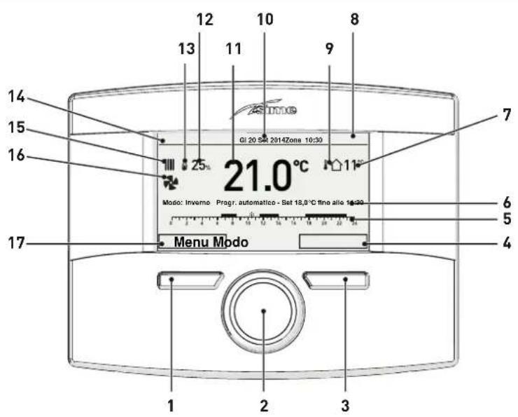
1 Button (A)
2 Multifunction encoder
3 Button (B)
4 Action carried out by pressing button (B)
5 Programmed time band
6 Mode selection
7 Measured outdoor temperature
8 Time
9 Presence of outdoor probe (SE)
10 Date
11 Measured ambient temperature
12 Modulation percentage
13 Flame
14 Controlled area
15 Request for heating (rad) or hot water (tap)
16 Heat pump operating
17 Action carried out by pressing button (A)
1.1.1 Using the buttons
With the appliance powered, from the "Main screen".

BUTTON (A)
(used mainly by professionally qualified technicians and NOT by the end user)
This allows technicians to view the "menu" select screen (e.g. Menu "GENERAL SETTINGS") and then to operate according to what is written above the button on the display (e.g. Esc to exit and return to the main screen.
![MENU GENERAL SETTINGS [...] INFORMATION [...] TECHNICAL EscBack](/content/2026/06/1396543/images/52700309bca4939725ebeb4a2218cc49a79747bb4e2a79e60d996abe9c150385.jpg)
MULTIFUNCTION ENCODER
If turned, (○) allows the user to scroll through and select the "Menu/rows" or the "Function mode", or to change the values in the selected field.
In "Summer" mode, the DHW temperature can be adjusted. In "Winter" mode, the DHW can be adjusted in relation to the heating and the "Holiday function".
![GENERAL SETTINGS [...] INFORMATION [...] TECHNICAL EscBack GENERAL SETTINGS [...] INFORMATION [...] TECHNICAL EscBack](/content/2026/06/1396543/images/7edc14538df4d7ee5e8bf59cccc9ee4d7589b51f7f5940b192625b3ca7074897.jpg)
If pressed, click confirms the selection and takes the user to the submenus (e.g. "LANGUAGE" or "Hot water") or confirms the modified value or entry.

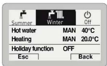
BUTTON (B)
This allows users to view the "Function mode" screen (e.g. "Winter") and then to operate according to what is written above the button on the display (e.g. Esc to exit and return to the main screen).
1.2 Start-up
1.2.1 Preliminary checks

WARNING
- Should it be necessary to access the areas in the bottom part of the appliance, make sure that the system components and pipes are not hot (risk of burning).
- Before replenishing the heating system, put on protective gloves.
Commissioning of the Murelle Revolution boiler must be carried out by professionally qualified personnel after which the boiler can operate automatically. It may however be necessary for the User to start the appliance autonomously without involving a technician: for example, after a holiday.
In this case, certain checks and the following operations must be carried out:
- check that the gas isolation and water system valves are open.
1.2.2 Ignition
After having carried out the preliminary checks, proceed as follows:
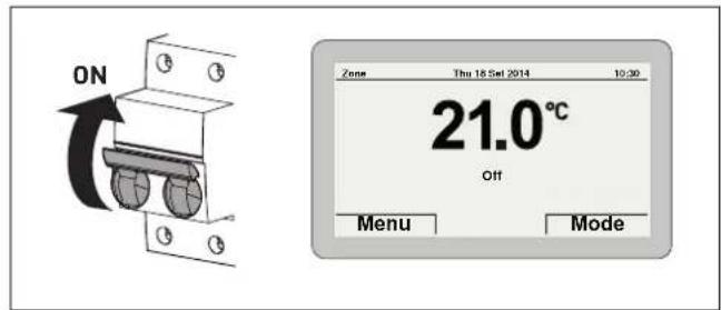
- set the main system switch to "ON"
- after a few seconds, the "Main screen" is shown
- Press the Mode button to view the "Function mode" (MODE) selection screen. Turn the encoder to select the preferred mode (e.g. "Winter")
- press the click encoder to confirm "Winter"
- press the Esc button to go back to the "Main screen"
Check the "System pressure" by doing as follows:
- press the Menu button to view the "Menu" selection screen
- turn the encoder to select the menu "INFORMATION"
![MENU GENERAL SETTINGS [..] INFORMATION [..] TECHNICAL EscBack GENERAL SETTINGS [..] INFORMATION [..] TECHNICAL EscBack [..]](/content/2026/06/1396543/images/90c327082659daf6da51eb5f336f663733d94865a2aef2ba9acf8897d0e36584.jpg)
- press the click encoder to confirm the highlighted "Mode" and go to the "rows"
- Turn the ( ) encoder to "Boiler"
![NECIVATION Zone heating Boiler [...] Heat pump [...] Hotwater [...] Solar thermal [...] ▼ Esc Back](/content/2026/06/1396543/images/105d3602d41805eb9f419ed5b9a34118e9eb5ad28ad4792e5a139e2271694fc6.jpg)
![[Zone heating Boiler [...] Heat pump [...] Hotwater [...] Solarthermal [...] Esc Back](/content/2026/06/1396543/images/f08dc6ccf998912c469dcfbf413d9ef6b10da2eb6f2249b8c5e5042aac9376c3.jpg)
- Press the click encoder to confirm the selection and go to the screen showing the "System pressure"

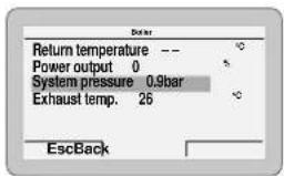
- check that the system pressure as shown when the system is cold, is between 1 and 1.2 bar. Where the value is different from 1-1.2 bar (the correct value), open the filling valve, which should be on the system return, until this value is reached and then shut it off again
- press the Esc button to go back to the "Main screen"

CAUTION
To view the "System pressure", the row does not need to be selected by turning the encoder.
- open one or more of the hot water valves and check that the appliance starts up

- allow the appliance to operate until hot water is produced and shut off the valves opened previously.
1.3 Settings using the MODE button
From the "Main screen":
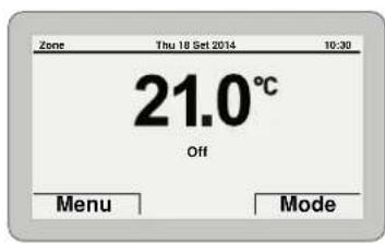
- Press the Mode button to view the "Function mode" selection screen. Turn the encoder to select a mode (e.g. "Winter")

- press the click encoder to confirm the highlighted "Mode" and go to the "rows"

- turn the encoder to select "Heating" (Heating) - press the click encoder to confirm "Heating" and access the "Rows"
![Function Mode MAN Set AUTO comfort 20.0°C Set AUTO reduced 18.0°C Set MAN 20.0°C Program. Time [...] Esc Back](/content/2026/06/1396543/images/3b4df55150596dc8c3aadceb68a0f1946bde0507dd4b642bbdc13dbdc2bade97.jpg)
- press the click encoder to confirm the highlighted "Row" and access the modifiable area
![Function Mode MAN Set AUTO comfort 20.0°C Set AUTO reduced 18.0°C Set MAN 20.0°C Program. Time [...] EscBack](/content/2026/06/1396543/images/43ce1208147761c955b2b11a79e2a4aae26db6b756f8ddf93afcbf3ed95aca93.jpg)
- turn the encoder to modify the "Data/value" in the permitted field (e.g. MAN - AUTO - OFF)
- Press the click encoder to confirm any modifications made and go back to the row "Function mode"
- turn the encoder to select another "Row" (e.g. "Program.Time").
![Function Mode MAN Set AUTO comfort 20.0°C Set AUTO reduced 18.0°C Set MAN 20.0°C Program. Time [...] EscBack](/content/2026/06/1396543/images/ebd0ed27f66618df91b187413d912c1f50e268d65f84b3ed6dd9e910e7a08bbd.jpg)
1.3.1 TimeProgramming
The main control panel (PCP) allows up to four daily time bands to be managed for the domestic hot water function and the heating function described below.
During the programmed time band, the boiler works in COM-FORT heating mode, while outside the programmed time band it works in REDUCED heating mode:
- press the click encoder to confirm the "Program. time" and go to the modifiable area
![HEATING TIME PROGRAM Day/s: MONDAY 0 2 4 6 8 10 12 14 16 18 20 22 24 [1] 06:00 - 08:00 [3] [2] 11:00 - 13:00 [4] 18:00 - 23:00 Esc Back](/content/2026/06/1396543/images/67623acfed45ec1763ab35fdb8bd91bda32668f4d371f184c7dcef77157f911b.jpg)
- turn the "encoder to select the "Single days" or the "Group of days"
- press the click encoder to confirm the required selection and access the first "Adjustable time" [1]
![HEATING TIME PROGRAM Day/s: MONDAY 0 2 4 6 8 10 12 14 15 18 20 22 24 [1] 06:00 - 08:00 [3] [2] 11:00 - 13:00 [4] 18:00 - 23:00 Cancel Confirm](/content/2026/06/1396543/images/ec583722133fe9efb058e3b8afda974c7e2b4cc735458800fe62df354b224430.jpg)
- turn the encoder to modify the "Data/value" on the basis of the required time
- press the click encoder to confirm the modification and move to the next "Data/value"
![HEATING TIME PROGRAM Day/s: MONDAY 0 2 4 6 8 10 12 14 16 18 20 22 24 [1] 06:00 - 08:00 [3] [2] 11:00 - 13:00 [4] 18:00 - 23:00 Cancel Confirm](/content/2026/06/1396543/images/0aad8b022fe0924d40277c6eff0499d0772817583056bdddc35af6c1b566696b.jpg)
- continue in this way until all the necessary modifications have been made for each day of the week or group of days.
NOTE: The user must work in a CIRCULAR manner, meaning ALWAYS MOVING FORWARDS, even if a mistake is made.

CAUTION
If NO time band is required, set the start and stop times of that band to the same value (e.g. [3] 14:00-14:00).
- Once the modification has been made, press the Confirm button to go back to "Single days" or "Group of days"
- press the Esc button to go back to the "Main screen".
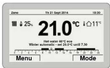
1.3.2 Holidayfunction
This function allows the user to deactivate both heating and hot water production during a "set and activated" holiday period, during which the antifreeze function can be active (if set).
To set the holiday function from the "Main screen":
- press the Mode button
- press the click encoder to confirm one of the Summer or Winter function mode
- turn the encoder to select "Holiday function"
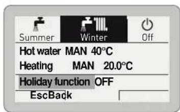
- press the encoder click to confirm the "Holiday function" (Holiday function) and go into the modifiable area

- turn the encoder to modify the "Data/value" which is highlighted - press the click encoder to confirm the modification and move to the next "Data/value"

- turn the encoder to modify the "Data/value" on the basis of the holiday start date
- press the click encoder to confirm the modification and move to the next "Data/value"
- continue in this way until all the necessary modifications have been made..
NOTE: The user must work in a CIRCULAR manner, meaning ALWAYS MOVING FORWARDS, even if a mistake is made.
- When all modifications have been made, press the Confirm button to go back to "Holiday function" - press the Esc button to go back to the "Main screen".

1.3.3 Fault warnings
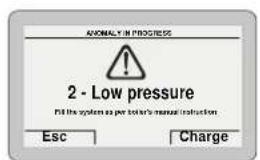
If a fault occurs, the screen "Anomaly in progress" (Fault in progress) will appear in place of the "main screen". For the main fault codes, a brief description and suggestions for the user are displayed, based on the seriousness and the frequency with which the fault reappears.


The fault may be transient (volatile) or it may cause an appliance block.
To restore normal operating conditions:
- if the fault is transient, eliminate the cause of the fault
- if the fault causes a block, remove the cause of the fault and then press the Reset button.
If there is "no water in the system" or "low water pressure in the system" there is a request to fill the system and then to press the Confirm button rather than the Reset button.


CAUTION
For a full list of faults, see "Malfunction codes and possible solutions".
1.3.4 Quick settings
The encoder allows the operator, specifically the user, to:
- change the "Set hot water" in SUMMER mode
- change the "Set room temperature" in WINTER mode.
In both cases, from the "Main screen":

- press the click encoder to display the set value


- turn the encoder to set the new "Set value"
- press the Confirm button to complete the modification and return to the "Main screen".
IMPORTANT INFORMATION FOR THE SET AMBIENT TEMPERATURE
The meaning of the words on the display is as follows:
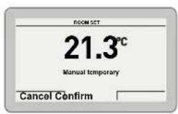
Manual temporary: the heating "Function mode" is set to AUTO and the set value read on the display is valid until the next time band change (automatic set point)
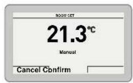
Manual: the heating "Function mode" is set to MAN and the set value read on the display is permanently valid.
1.4 Navigating using the MODE button

flowchart
graph TD
    A["MODE"] --> B["Summer"]
    A --> C["Winter"]
    A --> D["Off"]
    B --> E["Hot water MAN 50°C"]
    B --> F["Holiday function OFF"]
    E --> G["Function mode MAN"]
    E --> H["Hot water set 50°C"]
    E --> I["Time Programming [..."]]
    G --> J["Start: 01 01 2014 07:00"]
    H --> K["Stop: 08 01 2014 07:00"]
    J --> L["Enable holiday: NO"]
    K --> M["Hot water OFF - Heat. Off (Nofrost active)"]
    D --> N["Hot water MAN 50°C"]
    D --> O["Heating MAN 20.0°C"]
    D --> P["Holiday function OFF"]
    N --> Q["Function mode MAN"]
    N --> R["Hot water set 50°C"]
    N --> S["Time Programming [..."]]
    O --> T["Function mode MAN"]
    O --> U["Set AUTO comfort 20.0°C"]
    O --> V["Set AUTO reduced 18.0°C"]
    O --> W["Set MAN 20.0°C"]
    P --> X["Program. time [..."]]
    P --> Y["Set max flow 80°C"]
    T --> Z["Day/s: MONDAY"]
    U --> AA["Day/s: MONDAY"]
    V --> AB["Day/s: MONDAY"]
    W --> AC["Day/s: MONDAY"]
    X --> AD["Day/s: MONDAY"]
    Y --> AE["Day/s: MONDAY"]
    Z --> AF["Start: 01 01 2014 07:00"]
    AA --> AG["Stop: 08 01 2014 07:00"]
    AB --> AH["Enable holiday: NO"]
    AC --> AI["Hot water OFF - Heat. Off (Nofrost active)"]
    AD --> AJ["[1"]04:00-08:00["3"]16:00-18:15
[2]12:00-14:00["4"]20:30-22:30]
2.1 Servicing
As a condition of the warranty and to ensure correct operation and efficiency, it is important that the boiler is serviced every 12 months, within 30 days of the anniversary of the installation date ensure the required information is recorded in the Gas Boiler System Service Interval Record (Benchmark).

CAUTION
Maintenance interventions must ONLY be carried out by professionally qualified personnel who will follow the indications provided in the INSTALLATION AND MAINTENANCE MANUAL.
2.2 External cleaning

WARNING
- Should it be necessary to access the areas in the bottom part of the appliance, make sure that the system components and pipes are not hot (risk of burning).
- Before performing any maintenance, put on protective gloves.
2.2.1 Cleaning the case
When cleaning the cladding, use a cloth dampened with soap and water or alcohol for stubborn marks.

PROHIBITION
Do not use abrasive products.
3.1 Disposal of the equipment (European Directive 2012/19/EU)

At the end of their life span, the appliance and electrical and electronic devices coming from households or classifiable as household waste must be delivered to appropriate waste collection systems, in accordance with the law and with Directive 2012/19/EU. This product was designed and manufactured for minimising its impact on the environment and on human health, but it contains components that could be detrimental if managed improperly. The symbol (crossed-out wheelie bin) depicted here and also appearing on your appliance means that the appliance at the end of its life must be managed in accordance with the law and treated as electrical and electronic waste. Before delivering the appliance for its disposal, consult the applicable provisions of the laws in force in the country where the appliance is used and get information on the authorised waste disposal facilities by contacting the relevant local offices.

PROHIBITION
dispose of the product with urban waste.
DESCRIPTION OF THE APPLIANCE
TABLE OF CONTENTS
4 DESCRIPTION OF THE APPLIANCE 20
4.1 Characteristics 20
4.2 Operation summary 20
4.2.1 Heating 20
4.2.2 Domestic Hot Water (DHW)....20
4.3 Check and safety devices 21
4.4 Symbols on the appliance 21
4.5 Symbols on the packaging box 21
4.6 Identification 21
4.6.1 Technical data plates....22
4.7 Structure 23
4.8 Technical features....25
4.8.1 Boiler (gas side) 25
4.8.2 Heat pump 27
4.9 Main water circuit 28
4.10 Sensors 29
4.11 Expansion vessel....29
4.12 Circulation pump 29
4.13 Boiler control panel (gas side)....30
4.14 Heat Pump control panel 31
4.15 Main control panel (remote control) 31
4.15.1 Using the buttons 32
4.16 Wiring diagrams 33
4.16.1 Boiler 33
4.16.2 Heat pump 34
4.16.3 Interconnecting the appliance, outdoor air temperature probe and main control panel (remote control) 35
4 DESCRIPTION OF THE APPLIANCE
4.1 Characteristics
Murelle Revolution is an innovative Ccass A++ wall-mounted boiler designed by Sime Ltd SOLELY for space heating and producing domestic hot water.
The appliance is made up of a latest-generation sealed condensing gas boiler and a heat pump.
Murelle Revolution can ONLY operate if it is connected to the outdoor probe supplied with the appliance; if the outdoor probe is NOT connected, Murelle Revolution will NOT work.
The wall the appliance is mounted to must be able to support its weight, and preferably be an outside wall, to simplify installing the air inlet and outlet pipes.
Murelle Revolution can produce water for a heating system to a temperature of up to 75^ C. To obtain maximum performance from Murelle Revolution, the delivery temperature MUST NOT exceed 65^ C and the return temperature must not be above of 45^ C.
The main design choices made by Sime Ltd for Murelle Revolution boilers are:
- use of a sealed boiler with a total pre-mix microflame burner combined with a steel heat exchanger body and a rapid heat exchanger for DHW
- use of a modulating circulation pump
- use of a heat pump (HP), which is supported by the boiler to produce heat, and can operate separately or together with the boiler, according to the temperature detected by the outdoor probe
- a Main control panel (remote control) which serves both as an room thermostat and as a command and control device, a microprocessor, with bus protocol to manage the Murelle Revolution and related system
- use of a main evaporator with a patented smoke evaporator in series and a plate heat exchanger to transmit the heat to the water in the system. This allows the heat pump to operate with an average COP of 4.
- the option of being connected to room thermostats or chrono-thermostats for the zone.
The command board also has an internal connection where an expansion which can control the external relays can be inserted.
Murelle Revolution also has the following functions:
- the anti-freeze function which is activated automatically if the temperature of the water inside the boiler falls below the value set under "PAR 10" and if the outdoor temperature falls below the value set under "PAR 11"
- anti jamming function of the pump and diverter valve, this activates automatically every 24 hours if no request for heat has been made
- the chimney sweep function lasts 15 minutes and makes the job of the qualified technician easier when measuring the parameters and combustion efficiency
– domestic hot water comfort function which allows the time necessary for the hot water to become available to be reduced and ensures that the temperature is stable - screen display of the operating and self-diagnostic parameters with error code display when the fault occurs. This makes repair interventions easier and allows appliance operation to be restored correctly.
4.2 Operation summary
4.2.1 Heating
When there is a heating request from the main control panel (PCP) or from an room thermostat for the zone (TAZ), where there are no alarms and where the outdoor temperature is at least -7°C, the heat pump is activated (HP).
After a set period of time, calculated using an algorithm according to the current outdoor temperature, the gas boiler also starts up to help heat the water in the system and respond to the current request for heat.
When the system water temperature reaches the required value, also calculated using a specific algorithm for the gas boiler, the boiler stops and ONLY the heat pump continues to operate, until the heating request has been satisfied; after which, the heat pump also stops.

CAUTION
If, when there is a heating request, the outdoor temperature is below -7°C (e.g. -10°C), only the gas boiler is activated and the heat pump remains inactive.
4.2.2 Domestic Hot Water (DHW)
When there is a request for DHW, providing there is no heating request from the room thermostats, the diverter valve prepares to direct the flow of water towards the plate heat exchanger and the boiler starts up to respond to the request.
Should there be a request for heat at the same time, the heat pump stops and the boiler operates as described above. Once the DHW request has been satisfied, standard heating operation resumes.
4.3 Check and safety devices
The Murelle Revolution boilers are equipped with the following check and safety devices:
- thermal safety thermostat 100°C
- 3 bar relief valve
- heating water pressure transducer
- delivery sensor
- DHW sensor
- exhaust sensor.

PROHIBITION
Do not commission or operate the appliance with safety devices which do not work or which have been tampered with.

WARNING
Safety device may only be replaced by professional qualified personnel using Sime Ltd original spare parts.
4.4 Symbols on the appliance
The appliance is marked with the following symbols:
| SYMBOL DESCRIPTION | |
| Indicates the presence of particularly dangerous zones in the appliance. | |
| Indicates the presence of live electrical parts in the appliance. | |
| Indicates that information concerning the appliance is available, for example the instruction manual. | |
| Indicates that personnel assigned to perform maintenance on the appliance must operate in accordance with the instruction manual. | |
| Indicates that the instruction manual must be read. | |
| Indicates that the appliance must be connected to an earthing system. | |
4.5 Symbols on the packaging box
The packaging box contains the following symbols:
| SYMBOL DESCRIPTION | |
| Indicates the prohibition to stack the appliance. | |
| Indicates that the appliance must always be kept in the vertical position. | |
| Indicates that the appliance must be positioned with the side facing upwards. | |
4.6 Identification
The Murelle Revolution boilers can be identified by means of:
1 Packaging label: this is located on the outside of the packaging and provides a code, the serial number of the boiler and the bar code
2 Energy Efficiency Label: this is positioned on the outside of the packaging to notify the user of the energy savings and reduced environmental pollution of the "packet"
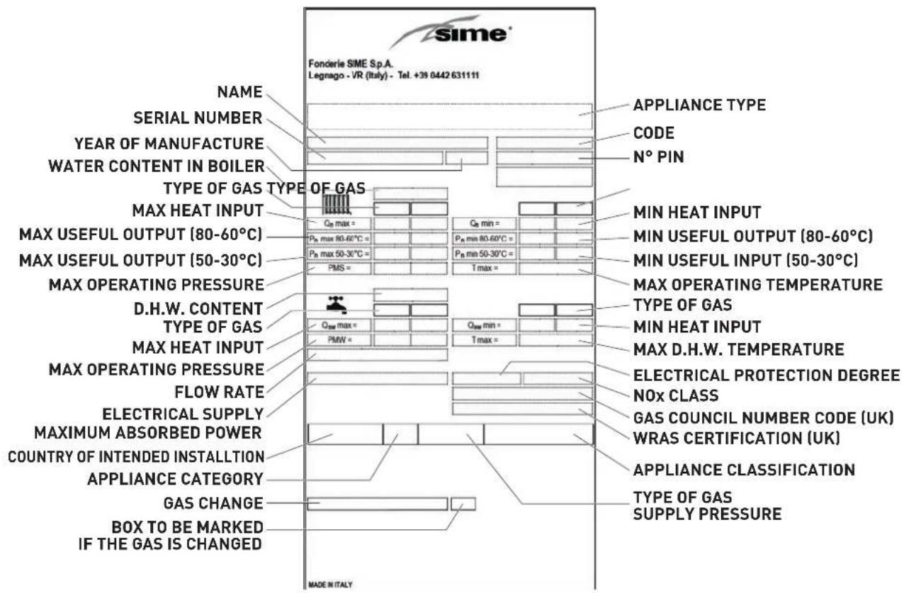
3 Heat pump technical data plate: this is located inside the front panel of the boiler and provides the technical data, appliance performance information and any other information required by law in the country where the appliance will be used.
4 Boiler technical data plate: this is located on the side of the appliance and provides the technical data, appliance performance information and any other information required by law in the country where the appliance will be used.


4.6.1 Technical data plates
Heat Pump Technical Data Plate

Boiler Technical Data Plate

CAUTION
Tampering with, removing or failing to display the identification plate or carrying out any other operation which does not allow safe identification of the product or which may hinder installation and maintenance operations.
4.7 Structure

1 Air inlet pipe
2 Gas boiler smoke evaporator
3 Heat exchanger bleed point
4 Heat exchanger
5 Exhaust sensor
6 Combustion chamber door
7 Air/gas duct
8 Flame viewing window
9 Ignition/detection electrode
10 Expansion vessel
11 Safety thermostat
12 Delivery sensor
13 Fan
14 Condensate siphon
15 Diverter valve
16 System filling unit
17 Domestic hot water sensor
18 Boiler control panel (gas side)
19 Domestic hot water heat exchanger
20 Gas valve
21 Automatic bleed valve
22 HP control panel
23 Return temperature probe
24 Domestic hot water filter
25 System relief valve
26 Boiler drain
27 Pump
28 Water pressure transducer
29 Plate capacitor
30 Air evaporator
31 Heat pump air outlet duct
32 Boiler smoke outlet duct
33 Boiler/heat pump air inlet duct

1 Condensate outlet
2 Safety valve outlet
3 Liquid level indicator
4 Boiler drain
5 Thermostatic expansion valve
6 HP by-pass solenoid valve
7 HP high pressure switch
8 HP low pressure switch
W4 Boiler connector (gas side) - Main control panel
W5 HP-main control panel connector
4.8 Technical features
4.8.1 Boiler (gas side)
| DESCRIPTION | Murelle Revolution 30 | |
| CERTIFICATIONS | ||
| Country of intended installation GB | ||
| Fuel G20; G31 | ||
| PIN number 1312CR6100 | ||
| Category II2H3P | ||
| Appliance classification C53 - C63 - C83 | ||
| Class NO×[1] 6 [< 56 mg/kWh] | ||
| DHW rated useful heat output kW | 28 | |
| HEATING PERFORMANCE | ||
| HEAT INPUT [2] | ||
| Nominal flow (Q n max) | kW | 20 |
| Nominal flow Q n (G20Y20) | kW | 19 |
| Minimum flow (Q n min) | kW | 4 |
| HEAT OUTPUT | ||
| Nominal (80-60°C) (P n max) | kW | 19,7 |
| Nominal (50-30°C) (P n max) | kW | 21,4 |
| Minimum G20 (80-60°C) (P n min) | kW | 3.9 |
| Minimum G20 (50-30°C) (P n min) | kW | 4.3 |
| Minimum G31 (80-60°C) (P n min) | kW | 3.9 |
| Minimum G31 (50-30°C) (P n min) | kW | 4.3 |
| EFFICIENCY | ||
| Max useful efficiency (80-60°C) | % | 98.5 |
| Min useful efficiency (80-60°C) | % | 97.5 |
| Max useful efficiency (50-30°C) | % | 107 |
| Min useful efficiency (50-30°C) | % | 107.5 |
| Useful efficiency at 30% of load (40-30°C) | % | 108.5 |
| Losses after shutdown at 50°C | W | 84 |
| DOMESTIC HOT WATER PERFORMANCE | ||
| Nominal heat input (Q nw max) | kW | 28 |
| Nominal heat input Q nw (G20Y20) | kW | 26,6 |
| Minimum heat input (Q nw min) | kW | 4 |
| Specific D.H.W. flow rate Δt 30°C (EN 13203) | l/min 12.9 | |
| Continuous D.H.W. flow rate (Δt 25°C/Δt 35°C) | l/min | 16,1 / 11,5 |
| Minimum D.H.W. flow rate | l/min | 2 |
| Max (PMW) / Min Pressure | bar | 7 / 0,5 |
| kPa | 700 / 50 | |
| ENERGY PERFORMANCE | ||
| HEATING | ||
| Heating seasonal energy efficiency class | A | |
| Heating seasonal energy efficiency | % | 93 |
| Sound power | db(A) | 54 |
| DOMESTIC HOT WATER | ||
| Domestic hot water energy efficiency class | A | |
| Domestic hot water energy efficiency | % | 84 |
| Stated domestic hot water profile load | XL | |
| ELECTRICAL SPECIFICATIONS | ||
| Power supply voltage | V | 230 |
| Frequency | Hz | 50 |
| Absorbed electrical power (Q n max) | W | 70 |
| Absorbed electrical power (Q n min) | W | 52 |
| Absorbed electrical power in stand-by | W | 3.6 |
| Electrical protection degree | IP | X5D |
| COMBUSTION DATA | ||
| Smoke temperature at Max/Min flow (80-60°C) °C 82 / 66 | ||
| Smoke temperature at Max/Min flow (50-30°C) °C 59 / 45 | ||
| Smoke flow Max/Min | g/s | 11,2 / 1,9 |
| Kg/h | 40,32 / 6,84 | |
| CO2 at Max/Min flow rate (G20) % 9,0 / 9,0 | ||
| CO2 at Max/Min flow rate (G31) % 10,0 /10,0 | ||
| O2 at Max/Min flow rate (G20) % 4,8 / 4,8 | ||
| NOx measured [3] mg/kWh 35 | ||
| NOZZLES - GAS | ||
| Number of nozzles No. 1 | ||
| Nozzle diameter mm 5.3 | ||
| Gas consumption at Max/Min flow rate (G20) | m3/h | 2,96 / 0,42 |
| Gas consumption at Max/Min flow rate (G31) | Kg/h | 2,17 / 0,31 |
| Gas supply pressure (G20) | mbar 20 | |
| kPa 2 | ||
| Gas supply pressure (G31) | mbar 37 | |
| kPa 3,7 | ||
| TEMPERATURE - PRESSURE | ||
| Max operating temperature (T max) | °C | 75 |
| Heating adjustment range | °C | 20÷75 |
| Domestic hot water adjustment range | °C | 10÷60 |
| Max operating pressure (PMS) | bar 2.5 | |
| kPa | 250 | |
| Water content in boiler | l | 4.65 |
[1] NOx class according to EN 15502-1:2021+A1:2023
[2] Heat input calculated using the lower heat output (Hi)
[3] Calculated with upper calorific value (Hs)
Lower Heat Output (Hi):
G20 Hi. 9.45 kW/m³ (15°C, 1013 mbar) - G31 Hi. 12.87 kW/kg (15°C, 1013 mbar)
Gas category G20Y20:
This appliance is suitable for G20 gas containing up to 20% hydrogen (H2). Due to variations in the percentage of H2, the percentage of O_2 may vary over time. This type of boiler automatically adjusts combustion on the basis of the type of gas used, so no adjustment is necessary when G20 gas containing up to 20% hydrogen is used.
4.8.2 Heat pump
| DESCRIPTION | Murelle Revolution 30 | |
| Model HYSIMO104M | ||
| HEATING PERFORMANCE | ||
| Heating water maximum temperature °C 50 | ||
| Heating water maximum pressure (DHWMP) bar 3 | ||
| Seasonal efficiency % 155 | ||
| Energy efficiency class of central heating A++ | ||
| Nominal power ( Q_n max) kW 4,0 | ||
| Refrigerant R-410A | ||
| Refrigerant load kg | 1,15 | |
| ELECTRICAL SPECIFICATIONS | ||
| Power supply voltage V | 230 | |
| Frequency Hz | 50 | |
| Nominal electrical power W | 1334 | |
| Maximum electrical power | 1650 | |
| Nominal absorption A | 6,0 | |
| Maximum absorption | 6,8 | |
| Protection rating against humidity and water penetration IP | X5D | |
| “CONTO ENERGIA TERMICO 2.0” RENEWABLE THERMAL ENERGY INCENTIVE | ||
| COP | 4,45 (*) | |
(*) Value obtained with:
- (*) External temperature = + 7°C
- Heat pump air input/output temperature = 30/35°C.
Performance table
| COP | USEFUL POWER | |||||||
| T AIR | T OUTLET HP | T OUTLET HP | ||||||
| 35,00 | 40,00 | 45,00 | 50,00 | 35,00 | 40,00 | 45,00 | 50,00 | |
| -7 | 3,64 | 3,14 | 2,77 | 2,49 | 3,53 | 3,20 | 3,01 | 2,84 |
| -2 | 3,81 | 3,29 | 2,90 | 2,60 | 3,84 | 3,48 | 3,27 | 3,09 |
| 2 | 4,06 | 3,50 | 3,09 | 2,77 | 4,10 | 3,71 | 3,49 | 3,30 |
| 7 | 4,24 | 3,65 | 3,22 | 2,89 | 4,35 | 3,94 | 3,71 | 3,51 |
| 10 | 4,30 | 3,71 | 3,27 | 2,94 | 4,40 | 3,98 | 3,75 | 3,55 |
| 12 | 4,36 | 3,76 | 3,32 | 2,98 | 4,45 | 4,03 | 3,79 | 3,59 |
| 15 | 4,41 | 3,80 | 3,35 | 3,01 | 4,48 | 4,06 | 3,82 | 3,61 |
Value of coefficient CC 0,97
4.9 Main water circuit
NOTE: see the legend at the beginning of the manual in the specific paragraph "LIST OF ABBREVIATIONS USED IN THE MANUAL".

flowchart
graph TD
    A["1"] --> B["3"]
    B --> C["4"]
    B --> D["5"]
    B --> E["6"]
    E --> F["7"]
    E --> G["8"]
    E --> H["9"]
    B --> I["10"]
    I --> J["21"]
    I --> K["22"]
    I --> L["23"]
    L --> M["14"]
    M --> N["13"]
    N --> O["15"]
    O --> P["16"]
    P --> Q["17"]
    Q --> R["18"]
    R --> S["29"]
    R --> T["28"]
    S --> U["25"]
    T --> V["26"]
    U --> W["35"]
    V --> X["37"]
    W --> Y["38"]
    X --> Z["30"]
    Y --> AA["31"]
    Z --> AB["32"]
    AA --> AC["33"]
    AB --> AD["34"]
    AC --> AE["MUGERSVI"]
KEY:
1 Primary heat exchanger
2 Domestic hot water sensor
3 Boiler fan
4 Thermal safety thermostat
5 Heating delivery probe
6 Domestic hot water heat exchanger
7 Diverter valve
8 Automatic by-pass
9 Condensate siphon outlet
10 Gas valve
11 Domestic hot water flow meter
12 Domestic hot water filter
13 Gas boiler outlet
14 System relief valve
15 Pump
16 Automatic bleed valve
17 Pressure transducer
18 System expansion vessel
19 HP water inlet probe
20 System flow cock
21 Gas cock
22 Domestic hot water inlet cock
23 System return cock
24 Return temperature probe
25 HP water outlet temperature probe
26 Plate heat exchanger
27 HP ON/OFF compressor
28 Expansion valve thermal bulb
29 HP low pressure switch
30 Liquid level indicator
31 Thermostatic expansion valve
32 Filter
33 Liquid receptacle
34 Air evaporator
35 HP high pressure switch
36 Smoke evaporator
37 Smoke HP by-pass solenoid valve
38 HP battery probe
4.10 Sensors
The sensors installed have the following characteristics:
- Dual sensor (thermal safety/output) NTC R25°C; 10kΩ β25°-85°C: 3435
- domestic hot water sensor NTC R25°C; 10kΩ β25°-85°C: 3435
- External temperature sensor NTC R25°C; 10kΩ β25°-85°C: 3435
| TR | 0°C | 1°C | 2°C | 3°C | 4°C | 5°C | 6°C | 7°C | 8°C | 9°C | ||||
| 0°C | 27279 | 26135 | 25044 | 24004 | 23014 | 22069 | 21168 | 20309 | 19489 | 18706 | Resistance R [Ω] | |||
| 10°C | 17959 | 17245 | 16563 | 15912 | 15289 | 14694 | 14126 | 13582 | 13062 | 12565 | ||||
| 20°C | 12090 | 11634 | 11199 | 10781 | 10382 | 9999 | 9633 | 9281 | 8945 | 8622 | ||||
| 30°C | 8313 | 8016 | 7731 | 7458 | 7196 | 6944 | 6702 | 6470 | 6247 | 6033 | ||||
| 40°C | 5828 | 5630 | 5440 | 5258 | 5082 | 4913 | 4751 | 4595 | 4444 | 4300 | ||||
| 50°C | 4161 | 4026 | 3897 | 3773 | 3653 | 3538 | 3426 | 3319 | 3216 | 3116 | ||||
| 60°C | 3021 | 2928 | 2839 | 2753 | 2669 | 2589 | 2512 | 2437 | 2365 | 2296 | ||||
| 70°C | 2229 | 2164 | 2101 | 2040 | 1982 | 1925 | 1870 | 1817 | 1766 | 1717 | ||||
| 80°C | 1669 | 1622 | 1577 | 1534 | 1491 | 1451 | 1411 | 1373 | 1336 | 1300 | ||||
| 90°C | 1266 | 1232 | 1199 | 1168 | 1137 | 1108 | 1079 | 1051 | 1024 | 998 | ||||
| 100°C | 973 |
Correspondence of Temperature Detected/Resistance
Examples of reading:
TR = 75^ R = 1925
TR = 80^ R = 1669.
4.11 Expansionvessel
The expansion vessel installed on the boilers has the following characteristics:
| Description U/M | Murelle Revolution 30 | |
| Total capacity l 9,0 | ||
| Prefilling pressure | kPa 100 | |
| bar 1,0 | ||
| Useful capacity l 5,0 | ||
| Maximum system content (*) l 124 | ||
(*) Conditions of:
Average operating temperature 70^ C (with high temperature system 80/60^ C)
Start temperature at system filling 10^ C.

CAUTION
- For systems with water content exceeding the maximum system content (as indicated in the table) an additional expansion vessel must be fitted.
- The difference in height between the relief valve and the highest point of the system cannot exceed 6 metres. If the difference is greater than 6 metres, increase the prefilling pressure of the expansion vessel and the system when cold by 0.1 bar for each meter increase.
4.12 Circulation pump
The flow-head performance curve available for the heating system is shown in the graph below.

line
| WATER FLOW RATE (l/h) | RESIDUAL HEAD (mbar) | | --------------------- | -------------------- | | 0 | 530 | | 200 | 500 | | 400 | 460 | | 600 | 420 | | 800 | 360 | | 1000 | 280 | | 1200 | 150 |
CAUTION
The appliance is equipped with a by-pass which ensures water circulation in the boiler when thermostatic valves are used in the system. The heating system design should incorporate a room thermostat. Thermostatic radiator valves fitted to all radiators except the room where the room thermostat is fitted. Properties with floor areas exceeding 150squre metres should be zoned.
4.13 Boiler control panel (gas side)
The boiler control panel can be used locally ONLY by the technical assistance service or by an authorised maintenance technician.

1 FUNCTIONAL BUTTONS
OR Press for more than one second and release to step through the operating modes (Stand-by - Summer - Winter). Also use this key to reset a resettable lockout.
During normal operation, pressing the button displays the domestic hot water set point which can be between 10 and 60°C. In "parameter setting", the engineer can scroll through the parameter index (decreasing) by pressing this button.
During normal operation, pressing the button displays the heating set point which can be between 20 and 80°C. In "parameter setting", the engineer can scroll through the parameter index (increasing) by pressing this button.
During normal operation, pressing this button allows the user to reduce the heating or DHW set point on the basis of the selection made previously. If there is a Remote Control (Open Therm), after having selected the heating button, the user can modify the incline of the climatic curve (decreasing it) by pressing the button (-). In "parameter setting/display", the engineer can modify the parameter setting or value (decreasing) by pressing this button.
During normal operation, pressing this button allows the user to increase the heating or DHW set point on the basis of the selection made previously. If there is a Remote Control (Open Therm), after having selected the heating button, the user can modify the incline of the climatic curve (increasing it) by pressing the button (+). In "parameter setting/display", the engineer can modify the parameter setting or value (increasing) by pressing this button.
Programming connector cover plug.
NOTE: pressing any one of these buttons for more than 30 seconds generates a fault on the display without preventing boiler operation. The warning disappears when the button is released.
2 DISPLAY

"SUMMER". This symbol appears when the boiler is operating in "Summer" mode or if only the domestic hot water mode is enabled via the remote control. If the symbols 🙏 and 🚫 are flashing, this indicates that the chimney sweep function is active.

"WINTER". This symbol appears when the boiler is operating in "Winter" mode or if both the domestic hot water and heating modes are enabled via the remote control. With the remote control, if no operating modes have been enabled both symbols 🙏 and 🚫 will be off.

"RESET REQUIRED". The message indicates that after having corrected the problem, normal boiler operation can be restored by pressing the button ⏻R.

"DOMESTIC HOT WATER". This symbol is present during a DHW request or during the "chimney sweep function" It flashes during the selection of the domestic hot water set point.

"HEATING". This symbol lights up during heating operation or during the "chimney sweep function It flashes during the selection of the heating set point.

"LOCKOUT" DUE TO NO FLAME.

"FLAME LIT".
"POWER LEVEL". This indicates the power level at which the boiler is operating.
PAR "PARAMETER". This indicates when the engineer is in parameter setting/display, or "info" or "counter", or in "activated alarms" (history).
ALL "ALARM". This indicates that a fault has occurred. The number specifies the cause which generated the alarm.
"CHIMNEY SWEEP". This indicates that the "chimney sweep function" has been activated.
. / bar "HEATING SYSTEM PRESSURE". Display of heating system pressure.
ECO "ECO", ALTERNATIVE ENERGY SOURCES. Where active, it indicates that there is a solar system available.
"MAINTENANCE REQUEST". If active, it shows it is time to perform maintenance on the boiler.
4.14 Heat Pump control panel
The heat pump control panel can be used locally ONLY by the technical assistance service or by an authorised maintenance technician.

1 Display
2 ON/OFF button
3 Decrease button
4 Increase button
5 Settings button
4.15 Main control panel (remote control)
The main control panel (PCP) allows all of the necessary adjustments to be made to Murelle Revolution and to the connected systems. It also serves as a main room thermostat and can therefore be used by all operators, users, authorised maintenance technicians and the technical service for the operations for which each of these figures is authorised, as described in detail in the relevant sections.
It communicates with the boiler control panel with an unpolarised bus line and OpenTherm protocol, and with the heat pump control panel with a RS485 polarised ModBus two-wire line.
It is equipped with a volt free input for remote control, where relevant (GSM-Dialler/WiFi).

1 Button (A)
2 Multifunction encoder
3 Button (B)
4 Action carried out by pressing button (B)
5 Programmed time band
6 Mode selection
7 Measured outdoor temperature
8 Time
9 Presence of outdoor probe (SE)
10 Date
11 Measured ambient temperature
12 Modulation percentage
13 Flame
14 Controlled area
15 Request for heating (rad) or hot water (tap)
16 Heat pump operating
17 Action carried out by pressing button (A)
4.15.1 Using the buttons
With the appliance powered, from the "Main screen".

BUTTON (A)
(used mainly by professionally qualified technicians and NOT by the end user)
This allows technicians to view the "menu" select screen (e.g. Menu "GENERAL SETTINGS") and then to operate according to what is written above the button on the display (e.g. Esc) to exit and return to the main screen.
![MENU GENERAL SETTINGS [...] INFORMATION [...] TECHNICAL EscBack](/content/2026/06/1396543/images/3cb79c92a5cdb226310992e34fa1d88aff941c152433e5d094ff9930b7710e74.jpg)
MULTIFUNCTION ENCODER
If turned, (○) allows the user to scroll through and select the "Menu/rows" or the "Function mode", or to change the values in the selected field. In "Summer" mode, the DHW temperature can be adjusted. In "Winter" mode, the DHW can be adjusted in relation to the heating and the "Holiday function".

![GENERAL SETTINGS [...] INFORMATION [...] TECHNICAL [...] Esc Back](/content/2026/06/1396543/images/b0b660ddace7a9434a95c0b4a34638a71110f91a86d3a66d79802f9074d8bb57.jpg)
If pressed, click confirms the selection and takes the user to the submenus (e.g. "LANGUAGE" or "Hot water") or confirms the modified value or entry.

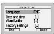

BUTTON (B)
This allows users to view the "Function mode" screen (e.g. "Winter") and then to operate according to what is written above the button on the display (e.g. Esc to exit and return to the main screen).


CAUTION
For more information, please see "Commissioning".
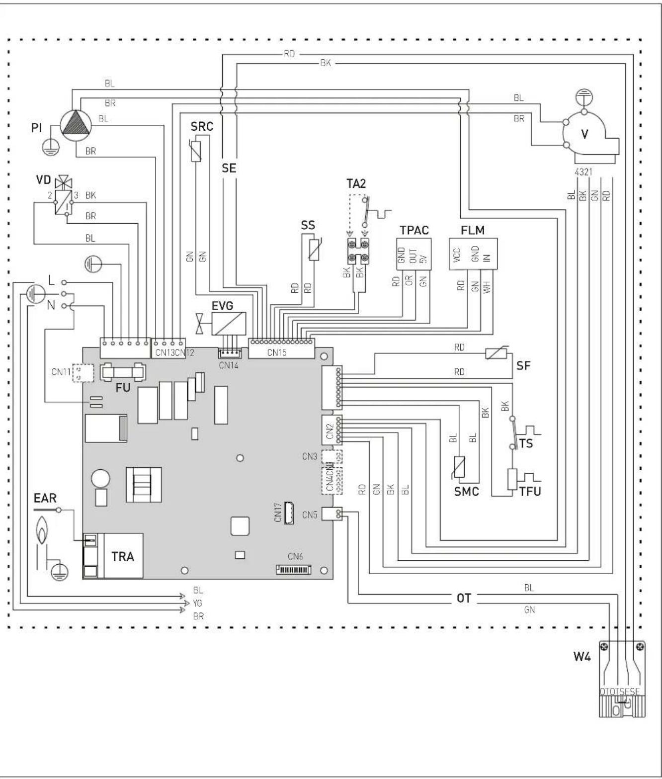
4.16 Wiring diagrams
NOTE: see the legend at the beginning of the manual in the specific paragraph "LIST OF ABBREVIATIONS USED IN THE MANUAL".
4.16.1 Boiler
4.16.2 Heat pump

flowchart
graph TD
    subgraph Power Supply
        A["V1"] --> B["4321"]
        C["VBP"] --> D["BL BL BL"]
        E["SCV"] --> F["BK"]
        G["SRI"] --> H["BK"]
        I["SMI"] --> J["BK"]
        K["HP"] --> L["BK"]
        M["LP"] --> N["BL BL BL"]
        O["FA"] --> P["BR BR BL"]
        Q["FU (500mAT)"] --> R["BL BL BL"]
        S["COMP"] --> T["BL BL BL"]
        U["COND"] --> V["GR"]
    end

    W["BR WH GN"] --> X["MCB"]
    Y["W5"] --> Z["BR WH"]
    style A fill:#f9f,stroke:#333
    style C fill:#f9f,stroke:#333
    style E fill:#f9f,stroke:#333
    style G fill:#f9f,stroke:#333
    style I fill:#f9f,stroke:#333
    style M fill:#f9f,stroke:#333
    style O fill:#f9f,stroke:#333
    style Q fill:#f9f,stroke:#333
    style S fill:#f9f,stroke:#333
    style U fill:#f9f,stroke:#333
    style X fill:#ccf,stroke:#333
    style Y fill:#ccf,stroke:#333
    style Z fill:#ccf,stroke:#333
    style W5 fill:#ccf,stroke:#333
    style YW5 fill:#ccf,stroke:#333
    style XW5 fill:#ccf,stroke:#333
    style YW5W5 fill:#ccf,stroke:#333
    style ZW5W5 fill:#ccf,stroke:#333
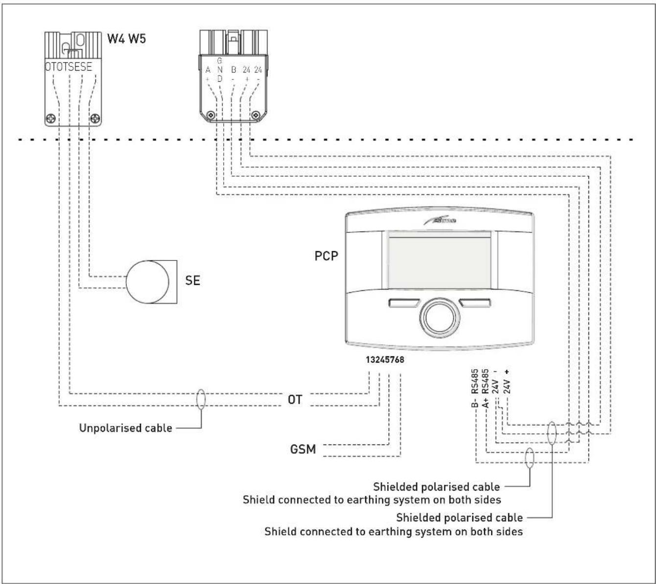
4.16.3 Interconnecting the appliance, outdoor air temperature probe and main control panel (remote control)
The connections below should be made by the installer and must be prepared before installing the main control panel (remote control), See "Mounting the main control panel (remote control)".

CAUTION
Installer must:
- To mount an omnipolar residual-current circuit breaker conforming to EN standards that allows for completely disconnecting the system in overvoltage category III conditions (that is, with a gap of at least 3 mm between the open contacts).
- Keep power cables always separate from signal cables. To avoid interference problems always use shielded signal cables.
- Respect the connections L (Live) - N (Neutral).
- Connect the earth wire to an effective earthing system.

CAUTION
Installer must:
- The system's power connection is of the "Y" type, so the power cable may only be replaced by the manufacturer or the service department.

CAUTION
Sime Ltd declines all responsible for any injury or damage to persons, animals, or property as a result of failure to provide adequate earthing of the appliance.

PROHIBITION
Do not use water pipes for earthing the appliance.
The Benchmark Scheme
Benchmark places responsibilities on both manufacturers and installers.
The purpose is to ensure that customers are provided with the correct equipment for their needs, that it is installed, commissioned and serviced in accordance with the manufacturer's instructions by competent persons and that it meets the requirements of the appropriate Building Regulations.
The Benchmark Checklist can be used to demonstrate compliance with Building Regulations and should be provided to the customer for future reference.
Installers are required to carry out installation, commissioning and servicing work in accordance with the Benchmark Code of Practice which is available from the Heating and Hotwater Industry Council who manage and promote the Scheme.
INSTALLATION AND SERVICING INSTRUCTIONS
Installer Checklist
Please remember to carry out the following checks after installation. This will achieve complete customer satisfaction, and avoid unnecessary service calls. A charge will be made for a service visit where the fault is not due to a manufacturing defect.
Has a correct by-pass been fitted and adjusted?
Has the system and boiler been flushed?
Is the system and boiler full of water, and the correct pressure showing on the pressure gauge?
Is the Auto Air Vent open?
Has the pump been rotated manually?
Is the gas supply working pressure correct?
Is the boiler wired correctly? (See installation manual).
Has the D.H.W. flow rate been set to the customer requirements?
Has the customer been fully advised on the correct use of the boiler, system and controls?
Has the Benchmark Checklist in the use and maintenance section of this manual, been completed?
TABLE OF CONTENTS
5 INSTALLATION 38
5.1 Receiving the product....38
5.2 Dimensions and weight 38
5.3 Handling 39
5.4 Ventilation requirements 39
5.5 New installation or installation of a replacement appliance 40
5.6 Cleaning the system 40
5.7 Characteristics of feedwater and system treatment .... 40
5.8 Boiler installation 41
5.9 Plumbing connections 42 5.9.1 Plumbing accessories (optional) 42
5.10 Condensate outlet/collection.... 42
5.11 Thermal insulation of the pipes....43
5.12 Gas supply 43
5.13 Connecting the flue....44
5.13.1 Flue Terminal Positions 44
5.13.2 Smoke outlet and air inlet (combustion/heat pump) 45
5.13.3 Smoke outlet (∅ 80 mm) 46
5.13.4 Coaxial ducts (Ø 160/200 mm) for air inlet/outlet (combustion/heat pump) ..... 46
5.13.5 Holes for air inlet/outlet 47
5.13.6 Fitting the air ducts 48
5.14 Mounting the main control panel (remote control) ..... 48
5.15 Electrical connections and External controls.....49
5.15.1 External temperature sensor....50
5.15.2 Chrono-thermostat or room thermostat for the zone 51
5.15.3 EXAMPLE of use of the command/control device on some types of heating systems .... 52
5.16 Refilling or emptying 53
5.16.1 Method of filling a sealed system.... 53
5.16.2 SYSTEM Filling....54
5.16.3 EMPTYING operations....54
6 COMMISSIONING 55
6.1 Preliminary operations.... 55
6.2 Before commissioning ..... 55
6.2.1 Automatic self-calibrating procedure ..... 55
6.3 Main control panel display and settings ..... 56
6.3.1 Settings using the MODE button ..... 56
6.3.1.1 Fault warnings 57
6.3.1.2 Quick settings 57
6.3.2 Navigating using the MODE button ..... 58
6.3.3 Settings using the MENU button 59
6.3.3.3 GENERAL SETTINGS menu 59
6.3.3.4 INFORMATION menu....61
6.3.3.5 TECHNICAL menu 61
6.3.3.6 TECHNICAL ASSISTANCE CENTRE menu....63
6.3.4 Navigating using the MENU button ..... 64
6.4 Parameter setting and display.... 65
6.5 Fault / malfunction codes 68
6.6 Display of operating data and counters ..... 69
6.7 Checks 70
6.7.1 Chimney sweep function....70
6.8 Domestic hot water comfort function (preheating) ..... 71
6.9 Gas conversion 71
7 MAINTENANCE 72
7.1 Servicing 72
7.2 External cleaning 72
7.2.1 Cleaning the case 72
7.3 Burner Inspection.... 72
7.3.1 Burner access 72
7.3.2 Cleaning the burner and the combustion chamber 73
7.3.3 Checking the ignition/detection electrode....73
7.3.4 Cleaning the smoke exchanger ..... 74
7.3.5 Final operations.... 74
7.3.6 Cleaning the heat pump 74
7.4 Checks 74
7.4.1 Checking the flue....74
7.4.2 Checking the expansion vessel pressure.....74
7.5 Circuit Board Replacement 75
7.6 Malfunction codes and possible solutions ..... 75
8 MURELLE REVOLUTION CHECKLIST 30 77
sime 5 INSTALLATION

CAUTION
The appliance must only be installed by the Sime Ltd Technical Service or by qualified professionals who MUST wear suitable protective safety equipment.
5.1 Receiving the product
Murelle Revolution is delivered in a single unit protected by cardboard packaging.
natural_image
Isometric line drawing of a rectangular box with a side frame (no text or symbols)The plastic bag found inside the packaging contains the following:
- Installation, use and maintenance manual
- Certificate of warranty
- Hydrostatic test certificate
- Hanging Bracket
- External sensor
- Main control panel (remote)
- Connection pack
- Boiler and heat pump energy labels
- Anti-vibration and spacer panels
– Paper template for boiler installation.

PROHIBITION
To leave packaging material around or near children since it could be dangerous. Dispose of it as prescribed by legislation in force.
5.2 Dimensions and weight

| Description | Murelle Revolution 30 |
| W (mm) 600 | |
| D (mm) 391 | |
| H (mm) 900 | |
| H1 (mm) 82,5 | |
| H2 (mm) 71 | |
| Weight (kg) 109 |
5.3 Handling
During transportation, the boiler must be kept in a vertical position, and knocks against walls or hard surfaces should be avoided.

natural_image
Illustration of a box with a checkmark and three crossed-out boxes below (no text or symbols)
PROHIBITION
- Position the appliance horizontally or on its side.
- To handle the appliance by stacking it on other appliances.
Once the packaging has been removed, handle the appliance manually by lifting it from the "solid" parts, such as the base and structure.


WARNING
When moving the appliance and removing the packaging, the user must:
- respect the maximum weight restrictions for lifting per person
- use suitable tools and safety devices.
5.4 Ventilation requirements
The room where the appliance is to be installed must comply with the technical regulations and legislation in force. No aeration vents are required because the approved installation is ONLY "TYPE C" (refer to the regulations). Moreover, it must be made in a way that prevents noise as far as possible during the appliance's operation.
The minimum temperature of the installation room must NOT be lower than -5 °C.

CAUTION
- Make sure that the appliance is protected against direct sunlight, the weather and damp and wet conditions.
- Before assembling the appliance, the installerMUST make sure that the wall supports the weight.
- Remember to consider the space needed in order to access the safety/adjustment devices and to carry out maintenance interventions.
APPROXIMATE MINIMUM DISTANCES


CAUTION
Observe the necessary height (A), to be defined during installation, for making the plumbing and gas connections.

CAUTION
In the case of flammable walls and penetrations, an insulating protection should be placed between the wall and the flue duct.
5.5 New installation or installation of a replacement appliance
The boiler must be installed in a fixed location and only by specialized and qualified person in compliance with all instructions contained in this manual.
The installation of this boiler must be in accordance with the relevant requirements of the current Gas Safety (installation and use), the local building regulations and I.E.E. wiring regulations. Detailed recommendations for air supply and fluing are given in BS5440.
The following notes are for general guidance: it is not necessary to have a purpose provided air vent in the room or compartment in which the appliance is installed.

CAUTION
It is a condition of the warranty that the boiler is installed in accordance with the instructions in this manual. The boiler must be registered with Gas Safe Register, the Benchmark record must be completed and the boiler is serviced annually and recorded in this manual.

CAUTION
If the domestic water supply is metered or should a water meter be added at a later time, a small expansion vessel should be included in the domestic water pipework.
5.6 Cleaning the system
Before installing the appliance on a newly constructed system or replacing a heat generator on an existing system, it is important that the system is thoroughly cleaned to remove sludge, slag, dirt, residue etc.
Before removing an old heat generator from an existing system, it is recommended that the user:
- puts a descaling additive into the water system
- allows the system to work with the generator active for a few days
- drains the dirty water from the system and flushes the system with clean water once or more than once.
If the old generator has already been removed or is not available, replace it with a pump to circulate water in the system and then proceed as described above.
Once cleaning operations have been carried out and before installing the new appliance, it is recommended that a fluid is added to the water system to protect it from corrosion and deposits.

CAUTION
- For further information on the type of additive and usage, please contact the appliance manufacturer.
- Please note that IT IS RECOMMENDED to install a Y-strainer on the return (R) of the heating system.
- It is advisable to install a defangator, not included with the appliance, upstream of the Y filter to collect and separate impurities in the system.
5.7 Characteristics of feedwater and system treatment
- All recirculatory systems will be subject to corrosion unless an appropriate water treatment is applied. This means that the efficiency of the system will deteriorate as corrosion sludge accumulates within the system, risking damage to pump and valves, boiler noise and circulation problems.
- Before connecting the boiler the associated central heating system must be flushed in accordance with the guidelines given in BS 7593 "Treatment of water in domestic hot water central heating systems".
- Sime Ltd recommends only the use of FERNOX products for the flushing and final treatment of the system water. This is particularly important in hard water areas. Failure to flush and add inhibitor to the system may invalidate the appliance warranty. Artificially softened water must not be used to fill the heating system. Naturally soft water areas can corrode aluminium heat exchangers. Adding Fernox F1 or Mb-1 will guard against corrosion.
- Sime Ltd promote the fitting of TF1 System filter with any new boiler installation.
- It is important to check the inhibitor concentration after installation, system modification and annually on a service visit in accordance with the manufacturer's instructions. (Note on benchmark service record this has been complete). Test kits are available from inhibitor stockists; the return of the Fernox test report should be kept with the Benchmark to validate warranty.
- Where Central heating systems are susceptible to freezing a mixture of inhibitor and anti-freeze should be added in accordance with the DWTA code of practice and the Manufactures instructions.
- The addition of sealing agents to system water is not recommended because deposits can be left in heat exchanger causing circulation issues.
5.8 Boiler installation
Before mounting the Murelle Revolution boiler on the wall, check that:
- the wall is solid enough to support the weight
- the required minimum clearance zones are respected
- it is an outside wall or one which allows the user to respect the maximum length of the air inlet and outlet pipes ( = 160/200 mm) (6 metres in total)
- the smoke outlet allows the user to respect the maximum length of the pipe (maximum permitted load loss)
- the water and gas supplies are easily accessible.
NOTE: Sime Ltd has created the "Wall-mounting bracket" KIT code 8081224 (not supplied with the product) to considerably reduce vibrations and noise in installations where these characteristics are important (e.g. internal rooms). If the kit is used, for the drilling operations refer to the instruction sheet accompanying the kit.

CAUTION
Attach the four circular spacers (1) supplied in front of and behind the fittings (2).
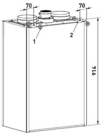
NOTE: if the "Wall-mounting bracket" kit code 8081224 is used, refer to the instruction sheet accompanying the kit.
Then:
- mark the two points where the holes are to be made to insert suitable expansion plugs that support the weight of the boiler
- mark the points where the holes (Ø 164 mm) are to be made to pass the air inlet and outlet and smoke outlet pipes through


* if the "Wall-mounting bracket" kit code 8081224 is used, the boiler will be mounted roughly 20 mm away from the wall.
- mount the boiler safely on the wall.

CAUTION
- The boiler should be located observing the required clearances, and provide safe, adequate service access.
- The manufacturer is not responsible for any damage to people, animals or objects following incorrect mounting of the appliance.

CAUTION
It is important that the device is perfectly vertical and horizontal. Use a spirit level or other suitable tool to check that it is perfectly vertical and horizontal. Where necessary, insert suitable spacers to install the unit in the correct working position.
5.9 Plumbing connections
The plumbing connections have the following characteristics and dimensions.
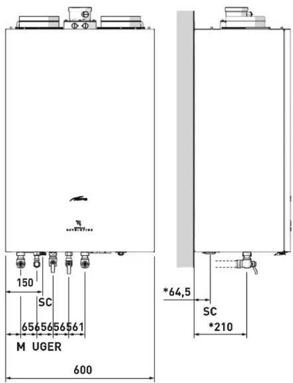
*if the "Wall-mounting bracket" kit code 8081224 is used, the boiler will be mounted roughly 20 mm away from the wall.
| Description | Murelle Revolution 30 |
| M - System flow ∅ 22 mm | |
| R - System return ∅ 22 mm | |
| U - Domestic hot water output ∅ 15 mm | |
| E - Domestic hot water inlet ∅ 15 mm | |
| G - Gas cock connection ∅ 15 mm | |
| SC - Condensate outlet ∅ 21.5 mm |

WARNING
You must fit a filter on the system return pipe.

WARNING
The discharge outlet of each safety valve installed must be connected to an appropriate collection and evacuation system. The manufacturer shall not be held liable for any flooding or damages to electrical equipment caused by the safety valve's intervention.
5.9.1 Plumbing accessories (optional)
To facilitate plumbing and gas connections to the systems, the accessories as shown in the table below are available and are to be ordered separately from the boiler.
| DESCRIPTION | CODE |
| Curve kit | 8075418 |
| Cocks kit | 8091806 |
| Wall mount replacement kit for other makers | 8093900 |
| Polyphosphate dosing kit | 8101700 |
| Dosing recharge kit | 8101710 |
NOTE: kit instructions are supplied with the accessory itself or are to be found on the packaging.
5.10 Condensate outlet/collection
In order to collect the condensate, it is recommended that:
- the appliance condensate outlets and the smoke outlet are ducted
- a neutralising device is prearranged
- the outlet incline is >3%.

CAUTION
- The condensate discharge pipe must NOT be modified or obstructed. It must be watertight, appropriately sized to match the siphon, and free from any restrictions..
- The condensate outlet must be constructed in full compliance of the National or Local regulations in force.
- Before the first commissioning of the appliance, fill the siphon with water and check that the condensate drains correctly..
- Periodically check that the condensate discharge pipe and/or the neutralisation system are free from blockages, and clean them if necessary depending on the type of obstruction detected..

WARNING
Using the appliance with an empty siphon may pose a risk of poisoning due to the possible escape of exhaust gases.
5.11 Thermal insulation of the pipes

CAUTION
Once the installation has been completed, it is necessary to insulate all exposed pipe sections and fittings using thermal insulation tubing of suitable dimensions.
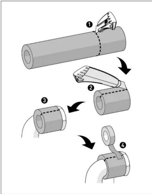
flowchart
graph TD
    A["Step 1: Cut the cylindrical tube"] --> B["Step 2: Cut the pin clip"]
    B --> C["Step 3: Cut the cylindrical tube with dashed lines"]
    C --> D["Step 4: Cut the cylindrical tube with ring handle"]
5.12 Gas supply
Murelle Revolution boilers leave the factory prearranged for gas G20 and can also work with G31 without the need for any type of mechanical conversion. Simply select parameter "03" (see "Parameter setting and display") and set the type of gas to be used.
Moreover, they are configured for working with G20 gas with a gas mixture containing up to 20% hydrogen H _2 .
If changing the type of gas to be used, carry out the entire appliance "COMMISSIONING" phase.
As a condition of the warranty and to ensure correct operation and efficiency, it is important that the boiler is serviced every 12 months, within 30 days of the anniversary of the installation date ensure the required information is recorded in the Gas Boiler System Service Interval Record (page 84) (Benchmark).
The gas connection must be made using seamless steel or copper tube.
Where the piping has to pass through walls, a suitable insulating sleeve must be provided.
When sizing gas piping, from the meter to the boiler, take into account both the volume flow rates (consumption) in m3/h and the relative density of the gas in question.
The sections of the piping making up the system must be such as to guarantee a supply of gas sufficient to cover the maximum output available from the boiler, limiting pressure loss between the gas meter and any apparatus being used to not greater than 1.0 mbar for family II gases (natural gas).
An adhesive data badge is sited inside the front panel; it contains all the technical data identifying the boiler and the type of gas for which the boiler is arranged.

WARNING
Once installation has been completed, check that the joints are air tight as indicated in the installation Standards.

CAUTION
It is recommended that the gas line has a suitable filter.

CAUTION
If the gas supply is changed from G20 to G31, mark the box on the TECHNICAL DATA PLATE.
G31 - 36 mbar

5.13 Connecting the flue

CAUTION
- The appliance must be installed as a room sealed device and unless stated in writing from the manufacturer, in accordance with the current edition of BS 5440-1. The information shown in this manual is for guidance and parts identification.
- Prior to fitting the flue, the condensate trap can be filled by carefully pouring water into the exhaust section of the flue connection.
5.13.1 Flue Terminal Positions

| Terminal position Minimum spacing | ||
| A Directly below an openable window, air vent or any other ventilation opening | 300 mm | 12 in |
| B Below guttering, drain pipes or soil pipes (**) | 75 mm | 3 in |
| C/D Below eaves, balconies or carport roof (*) | 200 mm | 8 in |
| E From vertical drain pipes or soil pipes | 75 mm | 3 in |
| F From internal or external corners | 300 mm | 12 in |
| G Above adjacent ground, roof or balcony level | 300 mm | 12 in |
| H From a boundary or surface facing the boiler | 600 mm | 24 in |
| I From a terminal facing the terminal | 1,200 mm | 48 in |
| J From an opening in the carport (eg door, window into dwelling) | 1,200 mm | 48 in |
| K Vertically from a terminal on the same wall | 1,500 mm | 60 in |
| L Horizont. from a terminal on the same wall | 300 mm | 12 in |
| M Horizont. from a vertical terminal to a wall | 300 mm | 12 in |
| N Horizont. from an openable window or other opening | 300 mm 12 in | |
| P Above an openable window or other opening | 300 mm 12 in | |
| Q From an adjacent vertical terminal | 600 mm | 24 in |
(*) This dimension to be used with ventilated soffits. With unvented soffits this can be reduced to 75 mm and further reduced to 25 mm when a flue shield is used to protect from the effects of heat and condensation.
(**) This can be reduced to 25 mm but it may be necessary to protect the surfaces from the effects of heat and condensation.
- If the terminal discharges into a pathway or passageway check that combustion products will not cause nuisance and that the terminal will not obstruct the passageway.
- Where the lowest part of the terminal is fitted less than 2 m [78 in] above ground, above a balcony or above a flat roof to which people have access, the terminal MUST be protected by a purpose designed guard.
- The air inlet/outlet flue duct MUST NOT be closer than 10 mm (0.4 in) to combustible material.
- In certain weather conditions the terminal may emit a plume of steam. This is normal but positions where this would cause a nuisance should be avoided.
5.13.2 Smoke outlet and air inlet (combustion/heat pump)

CAUTION
Murelle Revolution boilers must be installed and used with smoke outlet ducts and combustion/heat pump air inlet ducts fitted as specified below. If installed outside in a partially protected place, the basic configuration with a 90° elbow and inlet/outlet terminal is still required as a minimum.
Permitted types of exhausts and ducts

| Outlet | Description | Coaxial duct S | Separate ducts | |||
| ∅60/100mm | ∅80/125mm | ∅ 80mm | ∅ 60mm | ∅ 50mm | ||
| C53 | Separate wall or roof inlet and outlet in different pressure areas.NOTE: the inlet and outlet must never be positioned on opposing walls. | X | ||||
| C83 | Outlet in single or shared flue or with inlet on wall.Type 0 boilers are suitable for being connected to a natural draught pipe, with a maximum negative pressure of 1 mbar. The temperature of overheated combustion by-products is 2°C | X | ||||
| C63 | Outlet and inlet made from pipes which are sold and certified separately. | |||||

CAUTION
When the smoke outlet is wall mounted, the smoke outlet duct must be positioned at least 500 mm above the air duct.


WARNINGS
- The smoke flue and the connection to the flue pipe must be in compliance with the national and local standards and legislation in force in the country where the appliance will be used.
- The use of rigid ducts which are resistant to temperature, condensate, mechanical stress and are air-tight is compulsory.
- Outlet ducts which are not isolated are a risk of danger.
- The flue ducts can be made of plastic, resistant up to a maximum temperature of 120^ C, or stainless steel.
5.13.3 Smoke outlet (∅ 80 mm)

natural_image
Technical diagram of a mechanical component with three cylindrical parts and a labeled component (no text or symbols present)KEY:
1 Smoke outlet fitting
To assemble the smoke outlet, the accessories chosen from the table must be connected up.
Accessories
| Description | Code |
| Diameter ∅ 80 (mm) | |
| 90° curve M-F (6 pieces) 8077450 | |
| Extension W. 1000 mm (6 pieces) | 8077351 |
| Extension W. 500 mm (6 pieces) | 8077350 |
| Wall outlet terminal 8089501 | |
| Internal and external ring nut kit | 8091500 |
| 45° curve M-F (6 pieces) 8077451 | |
| Roof outlet terminal 8091204 | |
| Condensate recovery 8093300 |

CAUTION
The maximum length of the smoke outlet duct is determined by the load loss of the single accessories used and should not be more than 15 mm H20.
Load loss accessory ∅ 80 mm
| Description Code | Load loss (mm H2O) | |
| Murelle Revolution 30 | ||
| Outlet | ||
| 90° curve MF 8077450 0,30 | ||
| 45° curve MF 8077451 0,20 | ||
| Horizontal extension W. 1000 mm | 8077351 0,20 | |
| Vertical extension W. 1000 mm | 8077351 0,20 | |
| Wall terminal 8089501 0,35 | ||
| Roof outlet terminal 8091204 0,15 |
Example calculation of the load loss of a smoke outlet for aMurrelle Revolution 30 boiler.
| Accessories ∅ 80 mm Code | Quantity | Load loss (mm H2O) | ||
| Outlet | Total | |||
| Extension W. 1000 mm (horizontal) | 8077351 | 7 | 7 x 0,20 | 1,40 |
| 90° curve | 8077450 | 2 | 2 x 0,30 | 0,60 |
| Wall terminal | 8089501 | 2 | 0,35 | 0,35 |
| TOTAL | 2,35 | |||
(installation permitted since the total of the load loss of the accessories used is less than 15 mm H2O).
5.13.4 Coaxial ducts ( 160/200 mm) for air inlet/outlet (combustion/heat pump)
Coaxial ducts ( 160/200 mm) are used for the combustion air inlet and also for the heat pump inlet/outlet. A space is required between the two ducts to prevent condensation from forming.

KEY:
1 Combustion/heat pump air inlet
2 Heat pump air outlet
Air coaxial accessories
| Description | Code |
| ∅ 160/200 mm | |
| Extension MF PP ∅ 160/200 L=1000 | 8077360 |
| Extension MF PP ∅ 160/200 L=500 | 8077361 |
| Elbow ∅ 160/200 90° PP MUR. REV | 8089930 |
| Elbow ∅ 160/200 45° PP MUR. REV | 8089931 |
| Inlet/outlet terminal MUR. REVOL. | 8089550 |
Load loss - Equivalent lengths
| Model | Leq (linear metres) |
| 160/200 mm | |
| 90° curve | 1,5 |
| 45° curve | 1 |
Maximum lengths of straight tracks
| Model | Duct length ∅ 160/200 | |||
| L Horizontal (m) (*) | H Vertical (m) (*) | |||
| Inlet | Outlet | Inlet | Outlet | |
| Murelle Revolution 30 | 3 | 3 | 4 | 4 |
(*) The max. length of the straight track already includes a 90° elbow. Any shortening of one of the two tracks DOES NOT PERMIT equal lengthening of the other.
5.13.5 Holes for air inlet/outlet
Two holes are required for the appliance in the wall to channel the air inlet (1) and outlet (2) pipes outside.

- Carefully mark the centre of the holes to be made

Given the substantial size of the holes to be made in the wall, we recommended that suitable equipment (a core drill) be used, together with a suction system to limit the amount of dust and rubble.

CAUTION
The holes for channelling the inlet and outlet pipes outside must be slightly inclined downwards, to prevent any water coming in through the ducts.
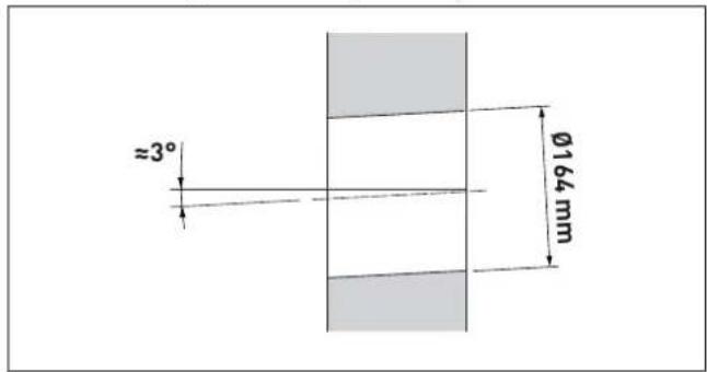

WARNING
When making the holes for channelling the inlet and outlet pipes outside, the majority of the material may be expelled outside; it is therefore important to check that it does not hit people or objects below as it falls. To avoid damaging the external plastering as far as possible, take extra care in the final stages of making the hole.

CAUTION
The manufacturer is not responsible for any damage to people, animals or objects following incorrect installation of the air inlet and outlet system.
5.13.6 Fitting the air ducts
- Cut the pipe (1) so that M1 = space between the wall and the elbow (A) + approximately 45 mm (insertion length of the pipe (1) in the elbow (3))
- cut the pipe (2) so that M2 = 160 + wall thickness (B) + space between the wall and the elbow (A) + approximately 60 mm (insertion length of the pipe (2) in the elbow (3))
- insert the rings (4) inside the pipe (1), then the pipe (1) in the elbow (3) and the assembled unit in the support (5)
- install the pipe (2), from the outside, until it is fully inserted in the elbow (3).

NB.: Ensure that the opening (6) is completely free so that any rain water can be drained.
5.14 Mounting the main control panel (remote control)

CAUTION
Before mounting the main control panel on the wall, the cables below must be prepared; these cables will then be connected to the terminals inside the control panel itself:
- Mod-Bus communication cable
- 24 V power cable 2 x 0.75 mm2
- OpenTherm communication cable
-
communication cable required to use a phone dialer for remote management, where relevant.
-
Remove the main control panel from the packaging
- use a screwdriver to push the fastening tab (1) to release the base (2) from the user interface (3), making sure that the screwdriver does not penetrate it

- separate the two parts
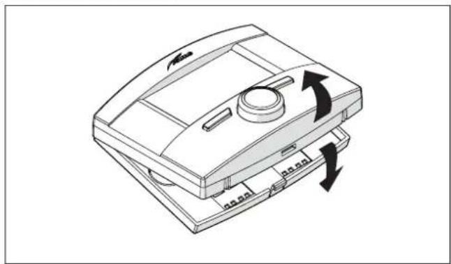
natural_image
Diagram of a device with directional arrows indicating rotation or movement (no text or symbols present)- connect the OpenTherm (OT) communication cables to the terminal (4)
- connect the communication cables that may be required to use a phone dialler for remote management to the terminal (5)
- connect the ModBus RS485 communication cables to the terminal (6)
- connect the 24 V power cables (2 x 0.75 mm ^2 ) to the terminal (7)
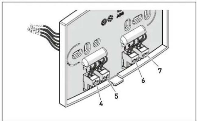
- secure the base (2) to the wall using the screws (8) and the plugs (9) supplied with the main control panel
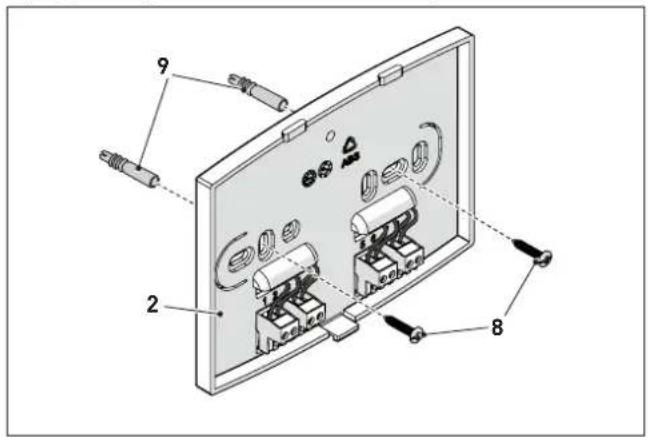
- refit the user interface (3) on the base (2), hooking the tab (1) on correctly.


CAUTION
Make sure that there is no excess cable between the base (2) and the user interface (3).
5.15 Electrical connections and External controls

CAUTION
Only qualified persons in compliance with the instructions contained in this manual are permitted to install, commission and maintain this boiler. The installation of this boiler must be in accordance with the relevant requirements of the current Gas Safety (installation and use) Regulation 1998, the local building regulations, and I.E.E. wiring regulations.
The installer should make the following electrical connections:
- connecting the wired power cable, supplied with the boiler, to the 230V\~50Hz mains
- connecting the outdoor probe, supplied with the appliance, to the specific connector on the boiler
- connecting the specific connector on the boiler to the terminals on the main control panel.

CAUTION
It is compulsory:
- to use an omnipolar cut-off switch, disconnect switch, in compliance with EN standards (contact opening of at least 3 mm)
- the system's power connection is of the "Y" type, so the power cable may only be replaced by the manufacturer or the service department
- to connect the earth wire to an effective earthing system
- keep power cables always separate from signal cables. To avoid interference problems always use shielded signal cables
- that before any work is done on the boiler, the mains power is disconnected by setting the main system switch to "OFF".

CAUTION
Sime Ltd declines all responsible for any injury or damage to persons, animals, or property as a result of failure to provide adequate earthing of the appliance.

PROHIBITION
Do not use water pipes for earthing the appliance.
The boiler is supplied with a mains cable. Connect the boiler to a 230V -50Hz single phase power supply through a fused mains switch, with at least 3 mm spacing between contacts, fused at 3 amps.
If this cable needs to be replaced, an original spare must be requested from Sime Ltd.
5.15.1 External temperature sensor
Murelle Revolution requires an outdoor probe. This is supplied and MUST be connected because the boiler uses the outdoor temperature detected to operate.

CAUTION
The boiler CANNOT FUNCTION unless the outdoor probe is installed.
Climatic curve
Delivery temperature

k=4 Factory settings
Procedure for selecting the climatic curve:
To select the preferred climatic curve:
- from the "Main screen" on the main control panel (PCP)

- press the Menu button to view the "Menu" selection screen

- turn the encoder to select the "TECHNICAL" menu
![MENU GENERAL SETTINGS [...] INFORMATION [...] TECHNICAL [...] Esc Back](/content/2026/06/1396543/images/eedb83319a7a36fac04f50ca8b6dc1689aee6494438285a431ead9dbca8c344e.jpg)
To proceed:

- press the click encoder to access the modifiable area. The following screen is displayed:
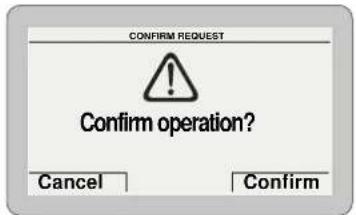
- press the Confirm button to access the submenus
![TECHNICAL State hybrid operation [...] Zone heating [...] Ht-boiler adjust. param. [...] Hot water [...] Boiler parameters [...] Esc Back](/content/2026/06/1396543/images/b8ed098922062e7e6bc6350627358765310277b1f23bd8267e89a9c1c737c0f8.jpg)
- turn the encoder to select the "Zone heating" submenu
![TECHNICAL Zone heating [...] Ht-boiler adjust. param. [...] Hot water [...] Boiler parameters [...] Advanced parameters Ht [...] Esc Back](/content/2026/06/1396543/images/8ebb7126dfe1173d68e8dbd3ef942150675fc8c8ff3da92c0e215a23391a928f.jpg)
- press the click encoder to access the modifiable parameters area

- turn the encoder to select the "Climatic curve" row

- press the encoder to confirm the highlighted "Row" and access the modifiable parameters.
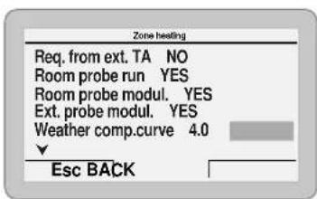
- turn the encoder to select the preferred climatic curve (from 1 to 9) according to the system requirements
- press the encoder to confirm the selection - press the Esc button to go back to the "Main screen".

CAUTION
The submenu "Hybrid func. status" is read-only.
5.15.2 Chrono-thermostat or room thermostat for the zone
The chrono-thermostat or room thermostat for the zone must be connected to terminals TA2 on the boiler control panel (gas side).
To set the MULTIZONE system configuration, operate the main control panel (PCP) as described below.
From the "Main screen":

- press the Mode button to access the "Function mode" select screen - turn the encoder to select "Winter" mode

- press the click encoder to confirm and access the "Rows" - turn the encoder to select "Heating" (Heating) - press the click encoder to confirm "Heating" and access the "Rows"
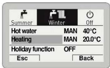
- turn the encoder to select "Function mode" - press the click encoder to confirm the "Function mode" and go to the modifiable area
![Function Mode MAN Set AUTO comfort 20.0°C Set AUTO reduced 18.0°C Set MAN 20.0°C Program. Time [...] Esc Back](/content/2026/06/1396543/images/ae30a5b3f91e5ce6d6f2d9ad83fb6153149cdf7c888c400468a16ea912981068.jpg)
- turn the encoder to select "OFF" - press the click encoder to confirm
![Heating Function Mode MAN Set AUTO comfort 20.0°C Set AUTO reduced 18.0°C Set MAN 20.0°C Program. Time [...] Esc Back](/content/2026/06/1396543/images/a1d29d128efa7d24eb185bc3772d839e142122fae52cdac383f7e6c14660aec5.jpg)
- press the Esc button to complete the modification and return to the "Main screen".
From the "Main screen":
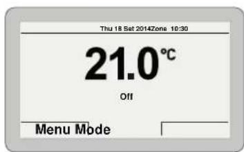
- press the Menu button to view the "Menu" selection screen
- turn the encoder to select the "TECHNICAL" menu
![MENU GENERAL SETTINGS [...] INFORMATION [...] TECHNICAL EscBack](/content/2026/06/1396543/images/68258606aa3a42bc60912c514293ff0ae81cdd31e7f666d49e95ee4912cb47ae.jpg)
To proceed:
- press the click encoder to access the modifiable area. The following screen is displayed:

- press the Confirm button to access the submenus
- turn the encoder to select the "Zone heating" submenu
![TECHNICAL Zone heating [...] Ht-boiler adjust. param. [...] Hot water [...] Boiler parameters [...] Advanced parameters Ht [...] ▼ Esc Back](/content/2026/06/1396543/images/9c59e3d4c457a2e19da6146c89df71605b7db83729c6f97391a547ec04fba383.jpg)
- press the click encoder to access the modifiable parameters area

- press and turn the encoder to change the settings as specified below:

| Req. from ext. TA | YES |
| Req. with room probe | NO |
| Mod. with room probe | NO |
| Mod. with ext. probe | YES |

- press the Esc button to complete the modification and return to the "Main screen".
The main control panel (PCP) then becomes a simple system operator with the relevant operating logic, and requests for heat for each zone are managed by the individual chrono-thermostats or ambient thermostats.
5.15.3 EXAMPLE of use of the command/control device on some types of heating systems
NOTE: see the legend at the beginning of the manual in the specific paragraph "LIST OF ABBREVIATIONS USED IN THE MANUAL".
ONE DIRECT ZONE system.

flowchart
graph TD
    A["PCP"] -->|SE| B["Heat Exchanger"]
    B --> C["Z"]
    style A fill:#f9f,stroke:#333
    style B fill:#ccf,stroke:#333
    style C fill:#cfc,stroke:#333
MULTI ZONE system – with pump and room thermostat.
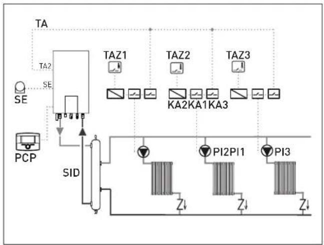
flowchart
graph TD
    A["PCP"] --> B["PID Controller"]
    B --> C["TA2/TAZ1/TAZ2/TAZ3"]
    C --> D["KA2 KA1 KA3 Controller"]
    D --> E["PI2 PI1 PI3 Controller"]
    E --> F["Z↓"]
    E --> G["Z↓"]
    E --> H["Z↓"]
MULTI ZONE system – with zone valve and room thermostats.
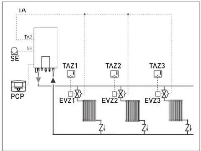
flowchart
graph TD
    A["PCP"] --> B["TA2"]
    B --> C["TEA"]
    C --> D["VA"]
    D --> E["VA"]
    E --> F["VA"]
    F --> G["VA"]
    G --> H["VA"]
    H --> I["VA"]
    I --> J["VA"]
    J --> K["VA"]
    K --> L["VA"]
    L --> M["VA"]
    M --> N["VA"]
    N --> O["VA"]
    O --> P["VA"]
    P --> Q["VA"]
    Q --> R["VA"]
    R --> S["VA"]
    S --> T["VA"]
    T --> U["VA"]
    U --> V["VA"]
    V --> W["VA"]
    W --> X["VA"]
    X --> Y["VA"]
    Y --> Z["VA"]
    Z --> AA["VA"]
    AA --> AB["VA"]
    AB --> AC["VA"]
    AC --> AD["VA"]
    AD --> AE["VA"]
    AE --> AF["VA"]
    AF --> AG["VA"]
    AG --> AH["VA"]
    AH --> AI["VA"]
    AI --> AJ["VA"]
    AJ --> AK["VA"]
    AK --> AL["VA"]
    AL --> AM["VA"]
    AM --> AN["VA"]
    AN --> AO["VA"]
    AO --> AP["VA"]
    AP --> AQ["VA"]
    AQ --> AR["VA"]
    AR --> AS["VA"]
    AS --> AT["VA"]
    AT --> AU["VA"]
    AU --> AV["VA"]
    AV --> AW["VA"]
    AW --> AX["VA"]

CAUTION
Set the parameter "tS 17 = DELAY SYSTEM PUMP AC- TIVATION to allow the opening of zone valve Vz.
5.16 Refilling or emptying
Before carrying out the operations described below, make sure that the main system switch is set to "ON"; after a few seconds, the main display will show on the Main control panel, and the pressure level in the system during refilling can be displayed.
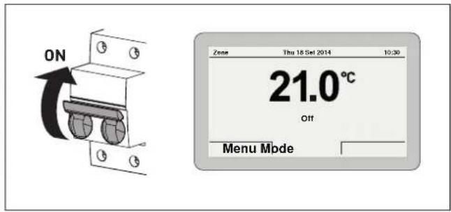
Press the Mode button and check that the appliance function mode is set to OFF.
If it is not OFF, turn the encoder to select OFF mode and press the click button to confirm.
5.16.1 Method of filling a sealed system
A sealed system must only be filled by a competent person using a method similar to that shown in figure below.

flowchart
graph LR
    A["Heating circuit return"] --> B["Stop valve"]
    B --> C["Hose unions"]
    C --> D["Double check valve"]
    D --> E["TAP"]
    E --> F["Stop valve"]
    F --> G["Mains water supply"]
    D --> H["Filling loop temporarily connected"]
5.16.2 SYSTEMFilling
The Murelle Revolution boilers are not equipped with a filling valve which must be prearranged on the system return. The procedure is described below.
Remove the front panel:
if the front panel has not already been removed, open the two catches (1), unscrew the two screws (2), pull the front panel (3) forwards and release it from the top by lifting it.

Domestic hot water circuit:
- open the isolation valves of the domestic hot water circuit (if present)
- open each of the DHW taps until air is expelled
- once bleeding has been completed, close the hot water valves.
Heating circuit:
- open the isolation and air bleeding valves in the highest points of the system
- loosen the automatic bleed valve (4)
- open the isolation valves of the heating circuit (if present)
- Open the filling valve (5)
- Fill until the water overflows from the air bleeding valves and shut off the valves again
- close the automatic bleed valve (4)
- Continue filling until the pressure reaches1-1.2 bar as shown on the display
- Close the filling valve (5)
- check that there is no air in the system by bleeding all the radiators and the circuit on the high points of the system

natural_image
Technical diagram of an industrial control room with visible piping, valves, and control panel (no text or labels)NOTE: to completely remove all air from the system, it is recommended that this operation is repeated a number of times.
- check the pressure on the display and if necessary top up until the correct pressure reading appears
- it is recommended that the condensate trap is filled prior to fitting the flue, by carefully pouring water into the exhaust connection.
Refit the front panel of the boiler hooking it on at the top, pushing it forwards and securing it by first closing the catches (1) and then tightening the screws (2) which were removed previously.
5.16.3 EMPTYING operations
Domestic hot water circuit:
- close the domestic hot water circuit isolation valve (prearranged in installation)
- open one or more than one hot water taps and drain the domestic hot water circuit.
Heating circuit:
- loosen the automatic bleed valve (4)
- close the heating circuit isolation valves (prearranged in installation)
- check that the filling valve (5) is shut-off
- connect a rubber hose to the boiler drain valve (6) and open it
- when it has fully emptied, close the drain valve (6)
- close the automatic bleed valve (4).
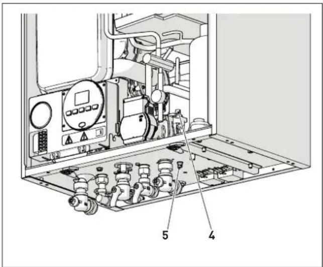
6.1 Preliminary operations

WARNING
- Should it be necessary to access the areas in the bottom part of the appliance, make sure that the system components and pipes are not hot (risk of burning). - Before replenishing the heating system, put on protective gloves.

CAUTION
Only qualified persons in compliance with the instructions contained in this manual are permitted to install, commission and maintain this boiler. Suitable protective safety equipment MUST be worn. The installation of this boiler must be in accordance with the relevant requirements of the current Gas Safety (installation and use), the local building regulations, and I.E.E. wiring regulations.
As a condition of the warranty and to ensure correct operation and efficiency, it is important that the boiler is serviced every 12 months, within 30 days of the anniversary of the installation date ensure the required information is recorded in the Gas Boiler System Service Interval Record (page 84) (Benchmark).
Before commissioning the appliance, check that:
- the type of gas is correct for the appliance
- the gas isolation valves for the heating system and the water system are open
- the siphon has been filled.
6.2 Before commissioning
After having carried out the preliminary operations, follow the procedure below, in order, to start the boiler:
- Set the main system switch to "ON"; after a few seconds, the "Main screen" is shown on the display

- press the Mode button to access the "Function mode" select screen
- turn the encoder to select a mode (e.g. "Summer")
- press the click encoder to confirm
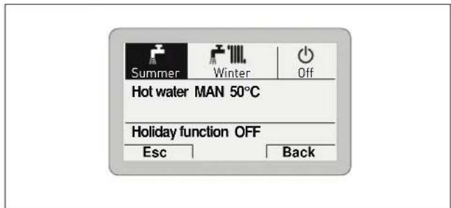
- disconnect and reconnect the electrical power supply by setting the main system switch to "OFF" and then to "ON"

NOTE: this operation allows the user to access the boiler control panel (local).
- the type of gas for which the boiler has been calibrated, "nG" (methane) or "LG" (LPG,) will appear followed by the power. Finally "-"will appear on the display

- check that the system pressure as shown when the system is cold, is between 1 and 1.2 bar
- press the button OR once for at least 1 second to select "SUMMER mode" ●. the value of the delivery sensor detected at that moment will appear on the display

6.2.1 Automaticself-calibratingprocedure
This type of boiler cannot be calibrated manually; take care to set the "Gas type configuration" parameter correctly according to the gas used.
Carry out the "Automatic self-calibrating procedure" as follows:
- press button ⚙ and set the DOMESTIC HOT WATER SET to maximum using the button +
- press and hold down the buttons - and + at the same time for approximately 10 seconds until the flashing symbols ⚙️ and
appear on the display

natural_image
Simple diagram with two star-like symbols above a horizontal line, no text or labels present.- as soon as the symbols begin to flash, release the buttons— and + and press the button ⏻R, within 3 seconds
- the "Automatic self-calibrating procedure" starts
- to dissipate the heat, tun on one or more DHW taps
- the values flash on the display: "100" (maximum value), followed by an "intermediate value" and finally "00" (minimum value)
| ** | ** | ** |
| 100 | 53 | 00 |
It may take up 15 minutes for the "self-calibrating procedure" to end and the message "SUMMER mode" ⚙️ to reappear on the display Once the procedure has terminated:
- close the taps opened previously and check that the appliance shuts down.
if there is a fault, the message "ALL" will appear on the display, the fault code (eg. "06" - no flame detected) and the message
RESET


CAUTION
To restore the start conditions press and hold the button OR for more than 3 seconds. This operation can be performed up to a maximum of 6 times without the "self-calibrating procedure" being interrupted.
- press the button ⏻R once for at least 1 second to select "WINTER mode" ⚙ The value of the heating water temperature detected at that moment will appear on the display

- operate the heating controls and check that the boiler starts and operates correctly
- using the procedure shown in section "Chimney sweep function" complete inlet working gas pressure test and a flue gas analysis.
6.3 Main control panel display and settings

CAUTION
We recommend not changing the factory settings so as not to alter optimal appliance operation. For any specific support, please contact the Sime Ltd Technical Assistance Service.
6.3.1 Settings using the MODE button
From the "Main screen":

- Press the Mode button to view the "Function mode" se-
lection screen. Turn the "Winter")
encoder to select a mode (e.g.

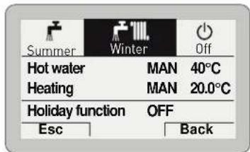
- press the click
- press the click encoder to confirm the highlighted "Mode" and go to the "rows"

- turn the encoder to select "Heating" (Heating)
- press the click encoder to confirm "Heating" and access the "Rows"
![Function Mode MAN Set AUTO comfort 20.0°C Set AUTO reduced 18.0°C Set MAN 20.0°C Program. Time [...] EscBack](/content/2026/06/1396543/images/abff20d5865d851bbf12a68241d276c0e40dac43abaa989dd022b7028c5e4246.jpg)
- press the click encoder to confirm the highlighted "Row" and access the modifiable area
![Function Mode MAN Set AUTO comfort 20.0°C Set AUTO reduced 18.0°C Set MAN 20.0°C Program. Time [...] EscBack](/content/2026/06/1396543/images/38c3c13d863596b824e2daf6ab58578aed309e303e3a7100917f8d0f5bad4af6.jpg)
- turn the encoder to modify the "Data/value" in the permitted field (e.g. MAN - AUTO - OFF) - Press the click encoder to confirm any modifications made and go back to the row "Function mode" - turn the encoder to select another "Row" (e.g. "Program.Time").

CAUTION
For information on using the functions "Time Programming and "Holiday function" see the relevant (section "User instructions").
6.3.1.1 Fault warnings
If a fault occurs, the screen "Anomaly in progress" (Fault in progress) will appear in place of the "main screen". For the main fault codes, a brief description and suggestions for the user are displayed, based on the seriousness and the frequency with which the fault reappears.


The fault may be transient (volatile) or it may cause an appliance block.
To restore normal operating conditions:
- if the fault is transient, eliminate the cause of the fault - if the fault causes a block, remove the cause of the fault and then press the Reset button.
If there is "no water in the system" or "low water pressure in the system" there is a request to fill the system and then to press the Confirm button rather than the Reset button.


A list of possible faults is given under "Fault / malfunction codes".
6.3.1.2 Quick settings
The encoder allows the operator, specifically the user, to:
- change the "Set hot water" in SUMMER mode - change the "Set room temperature" in WINTER mode. In both cases, from the "Main screen":
- press the click encoder to display the set value


- turn the encoder to set the new "Set value" - press the Confirm button to complete the modification and return to the "Main screen".


IMPORTANT INFORMATION FOR THE SET AMBIENT TEMPERATURE
The meaning of the words on the display is as follows:
Manual temporary: the heating "Function mode" is set to AUTO and the set value read on the display is valid until the next time band change (automatic set point)
Manual: the heating "Function mode" is set to MAN and the set value read on the display is permanently valid.
6.3.2 Navigating using the MODE button

flowchart
graph TD
    A["MODE"] --> B["Summer"]
    A --> C["Winter"]
    A --> D["Off"]
    B --> E["Hot water MAN 50°C"]
    B --> F["Holiday function OFF"]
    E --> G["Function mode MAN\nHot water set 50°C\nTime Programming [..."]]
    F --> H["Holiday schedule"]
    H --> I["Start: 01 01 2014 07:00\nStop: 08 01 2014 07:00\nEnable holiday: NO\nHot water OFF - Heat. Off (Nofrost active)"]
    G --> J["Hot water MAN 50°C\nHeating MAN 20.0°C"]
    G --> K["Holiday function OFF"]
    J --> L["Function mode MAN\nHot water set 50°C\nTime Programming [..."]]
    K --> M["Heating"]
    M --> N["Function mode MAN\nSet AUTO comfort 20.0°C\nSet AUTO reduced 18.0°C\nSet MAN 20.0°C\nProgram. time [..."]\nSet max flow 80°C]
    M --> O["Holiday schedule"]
    O --> P["Start: 01 01 2014 07:00\nStop: 08 01 2014 07:00\nEnable holiday NO\nHot water OFF - Heat. Off (Nofrost active)"]
    O --> Q["HEATING TIME PROGRAM"]
    Q --> R["Day/s: MONDAY"]
    R --> S["[1"]04:00-08:00["3"]16:00-18:15\n["2"]12:00-14:00["4"]20:30-22:30]
    style A fill:#f9f,stroke:#333
    style B fill:#ccc,stroke:#333
    style E fill:#ccc,stroke:#333
    style F fill:#ccc,stroke:#333
    style H fill:#ccc,stroke:#333
    style M fill:#ccc,stroke:#333
    style O fill:#ccc,stroke:#333
    style Q fill:#ccc,stroke:#333
    style R fill:#ccc,stroke:#333
6.3.3 Settings using the MENU button
6.3.3.3 GENERAL SETTINGS menu
From the "Main screen" on the main control panel (PCP), proceed as follows:

- press the Menu button to view the "Menu" selection screen
![MENU GENERAL SETTINGS [...] INFORMATION [...] TECHNICAL EscBack [...]](/content/2026/06/1396543/images/44e78de3ab4a521d3afda020f1bb6137724d0a11a19c4a79706c52ca989d43de.jpg)
- press the click encoder to confirm the highlighted menu and access the submenus
![GENERAL SETTINGS Language ENG Date and time [...] Visualization [...] Factory settings [...] Esc Back](/content/2026/06/1396543/images/8b1fe7d07a5a391a36da83faf61d0870ca6c0c26b3d55f9be984dc5f39811a8f.jpg)
- press the click encoder to confirm the highlighted submenu and select the modifiable area
![GENERAL SETTINGS Language ENG Date and time [...] Visualization [...] Factory settings [...] Esc Back](/content/2026/06/1396543/images/2581f63c234d48986463f9b6549f3c947f16fd9df063cdf55c75791c35e93802.jpg)
- turn the encoder and modify the "Data/value" in the permitted field (e.g. from ENG to ITA)
![GENERAL SETTINGS Language ENG Date and time [...] Visualization [...] Factory settings [...] Esc Back](/content/2026/06/1396543/images/bdfe9d87e07bf8bc63219f33e3cfa5c13b3ec0c67d023a738d5e75e652bd812d.jpg)
- press the click encoder to confirm the modification and go back to the submenu
![GENERAL SETTINGS Language ENG Date and time [...] Visualization [...] Factory settings [...] Esc Back](/content/2026/06/1396543/images/39a11ce54d81c03de926b8f6f1a91b5b0e5469affe1f88e67191813fca832446.jpg)
NOTE: press the Back button to go back one step, or press the Esc button to return to the "Main screen".
- turn the encoder to select another submenu (e.g. Date and time)
![GENERAL SETTINGS Language ENG Date and time [...] Visualization [...] Factory settings [...] Esc Back](/content/2026/06/1396543/images/5a36339c3fd175d3b820687be01f599d667c0b75979fe7f910a8149329f222da.jpg)
- press the click encoder to confirm the highlighted submenu and access the modifiable area

- the first modifiable "Data/value" is highlighted (e.g. 06)
- turn the encoder to modify the "Data/value" (e.g. from 06 to 12)
- press the click encoder to confirm the modification and select the next "Data/value" which will be highlighted (e.g. 36)

- turn the encoder to modify the "Data/value" (e.g. from 36 to 50)

- press the click encoder to confirm the modification and select the next "Data/value" which will be highlighted (e.g. 01)
- continue in this way until all the necessary modifications have been made.
- after all modifications have been made, press the button to go back to the initial submenu (Date and time). Confirm
NOTE: The user must work in a CIRCULAR manner, meaning ALWAYS MOVING FORWARDS, even if a mistake is made.
- turn the encoder to select another "Menu" (e.g. Display).
The "Display" menu allows the user to adjust:
- display contrast
- duration of the display back-lighting
- encoder back-lighting
The operating procedure is as has been described so far.
![GENERAL SETTINGS Language ENG Date and time [...] Visualization [...] Factory settings [...] Esc Back](/content/2026/06/1396543/images/c7af7e85365c863c62392bd47734755e86ac88bc44830bdaa29979af00f64eaf.jpg)

CAUTION
"Factory settings" submenu
It is recommended that the user access this submenu ONLY to restore the "Factory settings" (Factory settings), thereby deleting all settings made by the end user. Otherwise, press the Esc or Back button.
To proceed:
- press the click encoder to access the modifiable area. A screen appears offering the following options:

- press the Cancel button to go back to the "Menu" selected previously (Factory settings)
- press the Confirm button to restore the "Factory settings" and, after a few seconds, go back to the "main screen".
6.3.3.4 INFORMATION menu
The INFORMATION menu is read-only and the data cannot be modified.
From the "Main screen":
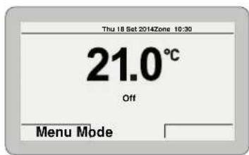
- press the Menu button to view the "Menu" selection screen
- turn the encoder to select the menu "INFORMATION"
![MENU GENERAL SETTINGS [...] INFORMATION [...] TECHNICAL EscBack](/content/2026/06/1396543/images/ed9de20afaeda0e3c3bf8a56c645d34b30a6cbf2e7ab85c5ce1a458ed0c6e850.jpg)
- press the click encoder to confirm "INFORMATION" and access the submenu

![INFORMATION ▲ Alarms [...] Esc Back](/content/2026/06/1396543/images/cc97437a7dee79ce4e0f02fbc7da4f69ca23367f9d5e0505bfe4cb7c98e5805f.jpg)
- turn the encoder to select the required submenu - press the click encoder to confirm the selected submenu and access the relevant data display
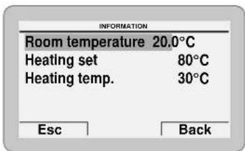
- press the Back button to go back to the submenus
- turn the encoder to select another submenu

![INFORMATION Boiler [...] Heat pump [...] Hot water [...] Solar thermal [...] Firmware version 102 Esc Back](/content/2026/06/1396543/images/cc56ebce01da588b00d4622ccf31bbeb1059de6a81aa8c0587233bcf3937b4f2.jpg)

click encoder to confirm the selected submenu he relevant data display
- continue in this way until all the necessary information has been shown
- press the Esc button to go back to the "main screen".

6.3.3.5 TECHNICAL menu
It is recommended that the TECHNICAL Menu only be used by professionally qualified technicians, since it is used to modify system management data.
The submenu "Boiler parameters" requires the CODE (or password) "1 2 3 4 5" to be entered.

CAUTION
We recommend not changing the factory settings so as not to alter optimal appliance operation. For any specific support, please contact the Sime Ltd Technical Assistance Service.
From the "Main screen":
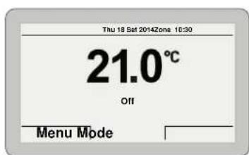
sime
- press the Menu button to view the "Menu" selection screen
- turn the encoder to select the "TECHNICAL" menu
![MENU GENERAL SETTINGS [...] INFORMATION [...] TECHNICAL EscBack](/content/2026/06/1396543/images/17ae5289240b1bf15c5752d60b1d6dea6818f6c3ab1e2abdb7ecf3cd0fcfac57.jpg)
To proceed:
- press the click encoder to access the modifiable area. The following screen is displayed:

- press the Cancel button to go back to the "TECHNICAL" menu
- press the Confirm button to access the submenus
![TECHNICAL State hybrid operation [...] Zone heating [...] Ht-boiler adjust. param. [...] Hot water [...] Boiler parameters [...] Esc Back](/content/2026/06/1396543/images/da077e9183adf166565d76b02f0294c57ea999291e608fe86eb3317d338e1a7f.jpg)
- turn the encoder to select the required submenu
- press the click encoder to confirm the selected submenu and access the modifiable parameters area.
[Non-Text]

CAUTION
When the submenu "Boiler parameters" is selected,
the following screen appears when the er is pressed:
click encod-

- turn the encoder to modify the first digit from 0 to 1 - press the click encoder to confirm the modification and select the next digit - continue in this way until the CODE (or password) "1 2 3 4 5" has been completed

- press the Confirm button to access the boiler "Parameter settings" area
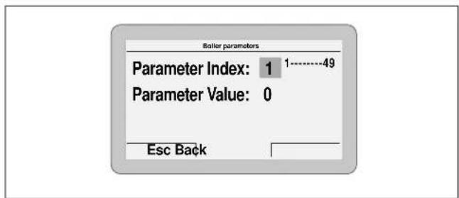
- where "Parameter index" refers to the parameter table "Parameter setting and display"
- Turn the encoder to scroll through the list of parameters and check the value.
If the value of the selected parameter is to be modified:
- press the click encoder to access the value modification area

- press the encoder to set the new value
- press the click encoder to confirm the modification and move on to another parameter
- once all the display/modification commands have been completed, press the Esc button to go back to the "Main screen".

6.3.3.6 TECHNICAL ASSISTANCE CENTRE menu

CAUTION
It is useful to enter the TECHNICAL ASSISTANCE CENTRE references which can then be displayed in the "Display menu" and suggested to the user if there is a serious fault with the boiler.
To enter the TECHNICAL ASSISTANCE CENTRE references:
- follow the procedure described in the section "TECHNICAL menu" up to "accessing the submenus"
- turn the encoder to select the "Technical Assistance Centre" submenu
![TECHNICAL State hybrid operation [...] Zone heating [...] Hot water [...] Boiler parameters [...] Alarm history reset [...] ✓ Esc Back TECHNICAL ▲ Customer service [...] Esc Back](/content/2026/06/1396543/images/f1f66bd0abf1b0b83a508f1b4579cc8f7191fba228f6da1462eae5181da30407.jpg)
- press the click encoder to confirm

- turn the encoder to select the first letter of the name
- turn the click encoder to confirm and move on to the next letter
- continue in the same way until the name is complete
- press the Confirm button to enter the telephone number. Proceed in the same way as for the name

- when this operation has been completed, press the Confirm button to return to the submenu. Press Esc to go back to the "Main screen".

6.3.4 Navigating using the MENU button

flowchart
graph TD
    A["MENU"] --> B["GENERAL SETTINGS"]
    B --> C["GENERAL SETTINGS"]
    C --> D["INFORMATION"]
    D --> E["SOLAR THERMAL ENERGY"]
    E --> F["ALARM HISTORY"]
    F --> G["CUSTOMER SERVICE"]
    G --> H["HOT WATER"]
    H --> I["BEAT PUMP"]
    I --> J["LOGICALS"]
    J --> K["DATA NOT BE NO OF SMOZZING."]
    K --> L["DATA NOT BE NO OF SMOZZING."]
    L --> M["DATA NOT BE NO OF SMOZZING."]
    M --> N["DATA NOT BE NO OF SMOZZING."]
    N --> O["DATA NOT BE NO OF SMOZZING."]
    O --> P["DATA NOT BE NO OF SMOZZING."]
    P --> Q["DATA NOT BE NO OF SMOZZING."]
    Q --> R["DATA NOT BE NO OF SMOZZING."]
    R --> S["DATA NOT BE NO OF SMOZZING."]
    S --> T["DATA NOT BE NO OF SMOZZING."]
    T --> U["DATA NOT BE NO OF SMOZZING."]
    U --> V["DATA NOT BE NO OF SMOZZING."]
    V --> W["DATA NOT BE NO OF SMOZZING."]
    W --> X["DATA NOT BE NO OF SMOZZING."]
    X --> Y["DATA NOT BE NO OF SMOZZING."]
    Y --> Z["DATA NOT BE NO OF SMOZZING."]
    Z --> AA["DATA NOT BE NO OF SMOZZING."]
    AA --> AB["DATA NOT BE NO OF SMOZZING."]
    AB --> AC["DATA NOT BE NO OF SMOZZING."]
    AC --> AD["DATA NOT BE NO OF SMOZZING."]
    AD --> AE["DATA NOT BE NO OF SMOZZING."]
    AE --> AF["DATA NOT BE NO OF SMOZZING."]
    AF --> AG["DATA NOT BE NO OF SMOZZING."]
    AG --> AH["DATA NOT BE NO OF SMOZZING."]
    AH --> AI["DATA NOT BE NO OF SMOZZING."]
    AI --> AJ["DATA NOT BE NO OF SMOZZING."]
    AJ --> AK["DATA NOT BE NO OF SMOZZING."]
    AK --> AL["DATA NOT BE NO OF SMOZZING."]
    AL --> AM["DATA NOT BE NO OF SMOZZING."]
    AM --> AN["DATA NOT BE NO OF SMOZZING."]
    AN --> AO["DATA NOT BE NO OF SMOZZING."]
    AO --> AP["DATA NOT BE NO OF SMOZZING."]
    AP --> AQ["DATA NOT BE NO OF SMOZZING."]
    AQ --> AR["DATA NOT BE NO OF SMOZZING."]
    AR --> AS["DATA NOT BE NO OF SMOZZING."]
    AS --> AT["DATA NOT BE NO OF SMOZZING."]
    AT --> AU["DATA NOT BE NO OF SMOZZING."]
    AU --> AV["DATA NOT BE NO OF SMOZZING."]
    AV --> AW["DATA NOT BE NO OF SMOZZING."]
    AW --> AX["DATA NOT BE NO OF SMOZZING."]
    AX --> AY["DATA NOT BE NO OF SMOZZING."]
    AY --> AZ["DATA NOT BE NO OF SMOZZING."]
    AZ --> BA["DATA NOT BE NO OF SMOZZING."]
    BA --> BB["DATA NOT BE NO OF SMOZZING."]
    BB --> BC["DATA NOT BE NO OF SMOZZING."]
    BC --> BD["DATA NOT BE NO OF SMOZZING."]
    BD --> BE["DATA NOT BE NO OF SMOZZING."]
    BE --> BF["DATA NOT BE NO OF SMOZZING."]
    BF --> BG["DATA NOT BE NO OF SMOZZING."]
    BG --> BH["DATA NOT BE NO OF SMOZZING."]
    BH --> BI["DATA NOT BE NO OF SMOZZING."]
    BI --> BJ["DATA NOT BE NO OF SMOZZING."]
    BJ --> BK["DATA NOT BE NO OF SMOZZING."]
    BK --> BL["DATA NOT BE NO OF SMOZZING."]
    BL --> BM["DATA NOT BE NO OF SMOZZING."]
    BM --> BN["DATA NOT BE NO OF SMOZZING."]
    BN --> BO["DATA NOT BE NO OF SMOZZING."]
    BO --> BP["DATA NOT BE NO OF SMOZZING."]
    BP --> BQ["DATA NOT BE NO OF SMOZZING."]
    BQ --> BR["DATA NOT BE NO OF SMOZZING."]
    BR --> BS["DATA NOT BE NO OF SMOZZING."]
    BS --> BT["DATA NOT BE NO OF SMOZZING."]
    BT --> BU["DATA NOT BE NO OF SMOZZING."]
    BU --> BV["DATA NOT BE NO OF SMOZZING."]
    BV --> BW["DATA NOT BE NO OF SMOZZING."]
    BW --> BX["DATA NOT BE NO OF SMOZZING."]
    BX --> BY["DATA NOT BE NO OF SMOZZING."]
    BY --> BZ["DATA NOT BE NO OF SMOZZING."]
    BZ --> CA["DATA NOT BE NO OF SMOZZING."]
    CA --> CB["DATA NOT BE NO OF SMOZZING."]
    CB --> CC["DATA NOT BE NO OF SMOZZING."]
    CC --> CD["DATA NOT BE NO OF SMOZZING."]
    AD --> CE["THECHNICAL CONFIRM REQUEST"]
    CE --> CF["THECHNICAL CONFIRM REQUEST"]
    CF --> CG["THECHNICAL CONFIRM REQUEST"]
    CG --> CH["THECHNICAL CONFIRM REQUEST"]
    CH --> CI["THECHNICAL CONFIRM REQUEST"]
    CI --> CJ["THECHNICAL CONFIRM REQUEST"]
    CJ --> DA["THECHNICAL CONFIRM REQUEST"]
    DA --> DB["THECHNICAL CONFIRM REQUEST"]
    DB --> DC["THECHNICAL CONFIRM REQUEST"]
    DC --> DD["THECHNICAL CONFIRM REQUEST"]
    DD --> DE["THECHNICAL CONFIRM REQUEST"]
    DE --> DF["THECHNICAL CONFIRM REQUEST"]
    DF --> DG["THECHNICAL CONFIRM REQUEST"]
    DG --> DH["THECHNICAL CONFIRM REQUEST"]
    DH --> DI["THECHNICAL CONFIRM REQUEST"]
    DI --> DJ["THECHNICAL CONFIRM REQUEST"]
6.4 Parametersettinganddisplay
To access the parameters menu from the "Main screen":

- press the Menu button to view the "Menu" selection screen
- turn the encoder to select the "TECHNICAL" menu
![MENU GENERAL SETTINGS [...] INFORMATION [...] TECHNICAL EscBack](/content/2026/06/1396543/images/f00e46434f3c743feb6171126123978a9707c708fcbaf4718bee60b6a13b198f.jpg)
To proceed:
- press the click encoder to access the modifiable area. The following screen is displayed:
- press the Cancel button to go back to the "TECHNICAL" menu
- press the Confirm button to access the submenus
![TECHNICAL State hybrid operation [...] Zone heating [...] Ht-boiler adjust. param. [...] Hot water [...] Boiler parameters [...] Esc Back](/content/2026/06/1396543/images/c7a03e1bc34943fef434814b65d990c52a49e77024b58c0fb7b450297df90b5c.jpg)
- turn the encoder to select the required submenu - press the click encoder to confirm the selected submenu and access the modifiable parameters area.
NOTE: The parameters below can be found in the submenu "HP-Boiler adjustment parameters".
| Type | No. | Description | Range | U/M Step | Default | |
| P 110 | T ON heating request | 0 ....10 | °C | 1 | 1 | |
| P 120 | T OFF heating request | 0 ....10 | °C | 1 | 4 | |
| P 130 | Outdoor probe temperature for boiler ON to boost | -5....15 | °C | 1 | 7 | |
| P 140 | Time 1 boiler ON (to support) | 0 ....60 | min | 1 | 20 | |
| P 150 | Time 2 boiler ON (to support) | 0 ....60 | min | 1 | 5 | |
| P 160 | T ON heating boost request | -20...20 | °C | 1 | 2 | |
| P 170 | T OFF heating boost request | -20...20 | °C | 1 | 1 | |
| P 180 | T set for heat pump | -10...10 | °C | 1 | 8 | |
| P 190 | Time 3 boiler ON (restart prevented) | 0 ...30 | min | 1 | 3 | |
| P 510 | Outdoor probe temp. for heat pump OFF | -15...0 | °C | 1 | -7 | |
| P 520 | Boiler activation to boost heating | Off/On | - | On | ||
| P 530 | Domestic hot water activation | Off/On | - | On | ||
| P 540 | Heat pump activation | Off/On | - | On | ||
| P 550 | HP maximum limit | 30...55 | °C | 1 | 47 | |
| Time Programming | [......] | - | - | - | ||
Once the HP-Boiler parameter setting is complete:
- press the Esc button - turn the encoder to select the "Boiler parameters" sub-menu
The following screen appears when the encoder is pressed as confirmation:

- turn the encoder to modify the first digit from 0 to 1
- press the click encoder to confirm the modification and select the next digit
- continue in this way until the CODE (or password) "1 2 3 4 5" has been completed

- press the Confirm button to access the boiler "Parameter settings" area

- The "Parameter index" refers to the parameter table below
- Turn the encoder to scroll through the list of parameters and check the value.
If the value of the selected parameter is to be modified:
- press the click encoder to access the value modification area

- press the encoder to set the new value
- press the click encoder to confirm the modification and move on to another parameter
- once all the display/modification commands have been completed, press the Esc button to go back to the "Main screen".

| Type | No. | Description | Range | U/M | Step | Default |
| CONFIGURATION | ||||||
| PAR | 01 | Index showing boiler power in kW | 6 = 30 (MURELLE REVOLUTION 30) | - | 1 | 6 |
| PAR | 02 | Hydraulic configuration | 0 = combi1 = system2 = N/A3 = N/A4=instant with solar power input | - | 1 | 0 |
| PAR | 03 | Gas Type Configuration | 0 = G201 = G31 | - | 1 | 0 |
| PAR | 04 | Combustion configuration0 = sealed chamber with combustion control | - | - | - | 0 |
| PAR | 08 | External sensor value correction | -5 .. +5 | °C | 1 | 0 |
| PAR | 09 | Ignition fan speed | 80 .. 160 | RPMx25 | 1 | 128 |
| DOMESTIC HOT WATER - HEATING | ||||||
| PAR | 10 | Boiler Antifreeze Threshold | 0 .. +10 | °C | 1 | 3 |
| PAR | 11 | External Sensor Antifreeze Threshold--- = Disabled | -9 .. +5 | °C | 1 | -2 |
| PAR | 12 | Heating Curve Incline | 0 .. 80 | - | 1 | 20 |
| PAR | 13 | Minimum Heating Temperature Adjustment | 20 .. PAR 14 | °C | 1 | 20 |
| PAR | 14 | Maximum Heating Temperature Adjustment | PAR 13 .. 80 | °C | 1 | 65 |
| PAR | 15 | Maximum power in CH mode | 0 .. 100 | % | 1 | 100 |
| PAR | 16 | Heating Post-Circulation Time | 0 .. 99 | seconds x 10 | 1 | 3 |
| PAR | 17 | Heating Pump Activation Delay | 0 .. 60 | seconds x 10 | 1 | 0 |
| PAR | 18 | Re-ignition Delay | 0 .. 60 | Min | 1 | 3 |
| Type No. Description Range U/M Step Default | ||||||
| PAR 19 | Domestic Hot Water Modulation with Flow meter | 0 = Disabled1 = Enabled | - 1 1 | |||
| PAR | 20 | Maximum power domestic hot water | 0 .. 100 | % | 1 | 100 |
| PAR 21 | Minimum power heating/domestic hot water (premixed) | 0 .. 100 % 1 0 | ||||
| PAR 22 | Domestic hot water preheating enabling | 0 = OFF1 = ON | - 1 0 | |||
| PAR 23 | External relay 1 function | 0 = not used1 = remote alarm NO2 = remote alarm NC3 = zone valve4 = automatic filling5 = external request6 = recirculation pump7 = zone valve with OT8 = relaunch pump9 = heat pump management | - | - 0 | ||
| PAR 24 | External relay 2 function | 0 = not used1 = remote alarm NO2 = remote alarm NC3 = zone valve4 = automatic filling5 = external request6 = recirculation pump7 = zone valve with OT8 = relaunch pump9 = heat pump management | - | - 0 | ||
| PAR 25 | Auxiliary TA function0 = according to TA | 1 = TA Antifreeze2 = domestic hot water disabled | - 1 0 | |||
| PAR | 26 | Zone Valve / Pump Relaunch Delay | 0 .. 99 | Min | 1 | 1 |
| PAR | 28 | DHW activation delay with solar power | 0 .. 30 | Min | 1 | 0 |
| PAR 29 | Anti-legionella Function (Only hot water tank)-- = Disabled | 50 .. 80 | - 1 -- | |||
| PAR | 30 | Maximum domestic hot water temperature | 10 .. 67 | °C | 1 | 60 |
| PAR 35 | Digital / analogue Pressure switch | 0 = water pressure switch1 = water pressure transducer (with ALL 09)2 = water pressure transducer (without ALL 09) | - 1 1 | |||
| PAR | 39 | Modulating pump minimum speed | 20 .. 100 | % | 1 | 55 |
| PAR 40 | Modulating Pump Speed | -- = No modulationAU = Automatic 30 100%PAR 39 100% | % | 10 | PM | |
| PAR | 41 | ΔT Modulating pump delivery/Return | 10 .. 40 | °C | 1 | 20 |
| PAR | 42 | Select heat pump or gas boiler switchover | -20 .. 30 | °C | 1 | 5 |
| PAR | 43 | Delay boiler activation to boost heat pump | 1 .. 180 | Min | 1 | 20 |
| PAR 47 | System pump forcing (only in winter mode) | 0 = Disabled1 = Enabled | - | - 0 | ||
| RESET | ||||||
| PAR | 48 | INST Parameter set to default | 0 .. 1 | - | - | 0 |
6.5 Fault / malfunction codes
If a fault occurs, the screen "Anomaly in progress" (Fault in progress) will appear in place of the "main screen". For the main fault codes, a brief description and suggestions for the user are displayed, based on the seriousness and the frequency with which the fault reappears.
| ANOVAILY IN PROGRESS | ANOVAILY IN PROGRESS |
| 5 - Technical problemContact customer serviceName: assessorPhone: 00000000Esc Back | 6 - No flame detectionReset boilerEsc Reset |
The fault may be transient (volatile) or it may cause an appliance block.
To restore normal operating conditions:
- if the fault is transient, eliminate the cause of the fault
- if the fault causes a block, remove the cause of the fault and then press the Reset button.
If there is "no water in the system" or "low water pressure in the system" there is a request to fill the system and then to press the Confirm button rather than the Reset button.
| ANORALLY IN PROGRESS | CONFIRM REQUEST |
| 2 - Low pressure | Confirm operation? |
| For the system as per below manual instruction | |
| Esc Charge | Cancel Confirm |
Boiler fault (gas side)
Type No. Description
ALL 01 Not used
ALL 02 Low water pressure in system
ALL 03 High water pressure in system
ALL 04 Domestic hot water sensor (SS) fault
ALL 05 Delivery sensor fault
ALL 06 No flame detection
ALL 07 Safety thermostat intervention
ALL 08 Fault in the flame detection circuit
ALL 09 No water circulating in the system
ALL 10 Auxiliary sensor fault
ALL 11 Gas valve modulator disconnected
ALL 12 Incorrect configuration of the open / sealed chamber
ALL 13 Exhaust sensor intervention
ALL 14 Exhaust sensor fault
ALL 15 Fan check cable disconnected
ALL 18 Condensate level fault
ALL 28 Maximum number of consecutive resets (6)
ALL 30 Return sensor (SR) fault
ALL 37 Fault due to low network voltage
ALL 40 Incorrect supply frequency detected
ALL 41 Flame loss more than 6 consecutive times
ALL 42 Button fault
ALL 43 Open Therm communication fault
ALL 44 No flame valve opening time sum anomaly
ALL 62 Self-calibrating procedure is required
Type No. Description
ALL 72 Incorrect positioning of the delivery sensor
ALL 77 EV2 SGV current max/min absolute limits error
ALL 78 EV2 SGV current upper limit error
ALL 79 EV2 SGV current lower limit error
ALL 80 Fault on the valve control logic line/valve cable damaged
ALL 82 Block due to numerous combustion control failures
ALL 84 Flow rate reduced for (presumed) low pressure on mains gas
ALL 88 Internal error (board component protection)
ALL 89 Unstable combustion feedback signal error
ALL 90 Combustion set cannot be reached error
ALL 92 System has reached maximum air correction error (at the minimum flow rate)
ALL 93 Combustion set cannot be reached error
ALL 95 Flame signal micro interruptions error
ALL 96 Lockout due to flue (exhaust) blockage
ALL 98 SW error, board start-up
ALL 99 General board error
Heat pump fault
Type No. Description
P 02 High pressure
P 04 Low pressure
P 12 Antifreeze (heat exchanger temp. < 3°C)
P 15 High temperature (HP delivery temp. > 50°C)
P 32 Probe errors aggregate (one or more probes with an active alarm)
P 33 Battery temperature probe error
P 34 Inlet water temperature probe error
P 35 Outlet water temperature probe error

CAUTION
As a condition of the warranty and to ensure correct operation and efficiency, it is important that the boiler is serviced every 12 months, within 30 days of the anniversary of the installation date ensure the required information is recorded in the Gas Boiler System Service Interval Record (page 84) (Benchmark).
6.6 Display of operating data and counters
Once the boiler is operating a qualified technician can view the operating data and the counters as follows:>
- from the boiler control panel screen (gas side) in the mode
enabled at that time (WINTER or SUMMER)


- go into "DISPLAY" by pressing the buttons 🎋 and — at the same time for more than 3 seconds until the following screen appears
From this point, the technician has 2 options:
- scroll through the list of "information (PAR)" and "counters
(PARc) ^™ by pressing the button 1111. Scrolling will be in sequence
- display the "activated alarms" (no more than 10) by pressing the button
- Once in this section, proceed with button 111 or 2.
When all the values have been displayed, exit the menu by pressing and holding down the button OR for approximately 5 seconds until the initial screen is displayed.

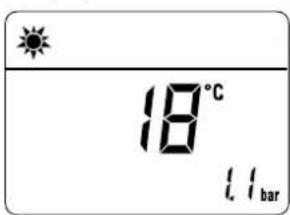
TABLE OF INFORMATION DISPLAYED
| Type No. Description | Range | U/M Step | |||
| PAR 00 | SW version | ||||
| PAR 01 | External temperature sensor | -9..99 | °C 1 | ||
| PAR 02 | Delivery sensor temperature | -9..99 | °C 1 | ||
| PAR 03 | Exhaust temperature (SF) | -9..99 | °C 1 | ||
| PAR 04 | Domestic hot water sensor temperature | -9..99 | °C 1 | ||
| PAR 05 | AUX auxiliary sensor | -9..99 | °C 1 | ||
| PAR 06 | Actual heating SET temperature | Par.13...Par.14 | °C 1 | ||
| PAR 07 | Power level | 0..99 | % | 1 | |
| PAR 08 | DHW flow rate | 0..99 | l/min 0.1 | ||
| PAR 09 | Water pressure transducer reading | 0..99 | bar | 0.1 | |
| PAR 10 | Actual speed fan number | 0..99 | RPM x 100 | 1 | |
TABLE OF COUNTER DISPLAYED
| Type No. | Description | Range | U/M Step | |
| PAR c0 | total no. of boiler operating hours | 0..99 | h x 1000 | |
| PAR c1 | total no. of burner operating hours | 0..99 | h x 1000 | |
| PAR c2 | total no. of burner ignitions | 0..99 | h x 1000 | |
| PAR c3 | total no. faults | 0..99 | x 1 | 1 |
| PAR c4 | total no. of times installer parameters "ALL"accessed | 0..99 | x 1 | |
| PAR c5 | total no. of times OEM parameters accessed | 0..99 | x 1 | |
| PAR c6 | Countdown to the next service | 1..199 | months 1 |
TABLE OF ACTIVATED ALARMS/FAULTS
| Type No. | Description | |
| PAR | A0 | Last activated alarm/fault |
| PAR | A1 | Last but one activated alarm/fault |
| PAR | A2 | Third from last activated alarm/fault |
| PAR | A3 | Previous activated alarm/fault |
| PAR | A4 | Previous activated alarm/fault |
| PAR | A5 | Previous activated alarm/fault |
| PAR | A6 | Previous activated alarm/fault |
| PAR | A7 | Previous activated alarm/fault |
| PAR | A8 | Previous activated alarm/fault |
| PAR | A9 | Previous activated alarm/fault |
6.7 Checks
6.7.1 Chimney sweep function
The chimney sweeper function is used by the qualified maintenance technician to check the mains gas pressure, detect the combustion parameters and to measure the combustion efficiency. A combustion analysis should not be conducted until a satisfactory inlet working pressure test has been completed.
This function lasts 15 minutes and is activated by proceeding as follows:
- if the front panel has not already been removed, open the two catches [1], unscrew the two screws [2], pull the front panel [3] forwards and release it from the top by lifting it.
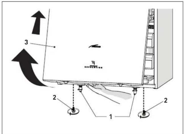
- remove the screws (4) securing the control panel (5)
- move the panel (5) upwards (a) but keeping it in the side guides (6) to the end of travel
- bring it forwards and down (b) until it is horizontal

- isolate the gas cock
- loosen the screw of the "mains pressure" point (7) and connect a pressure gauge
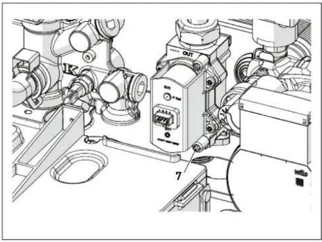
natural_image
Technical line drawing of a mechanical assembly with no visible text or symbols- open the gas cock
- power the boiler by setting the main switch to "ON"

- press the button y for at least 1 second until "SUMMER" mode 1 has been selected
- press and hold down the buttons
at the same time for approximately 10 seconds until the message "Hi" appears on the display together with the flashing symbols ] and n

- press the button > to make the boiler operate at maximum power "Hi" and check that the mains gas pressure value on the pressure gauge is correct.
- press the button < to make the boiler operate at minimum power "Lo". The message "Lo" will appear on the display together with the flashing symbols ] and n

- take the combustion data reading
- press the button ⏻R to exit the "Chimney sweeper Procedure". The boiler water delivery temperature will appear on the display

- disconnect the pressure gauge, carefully close the pressure point (6), test for gas tightness, put the control panel back to the original position and refit the front panel (2). Now conduct a flue gas analysis as detailed in APPENDIX 2.
Gas supply pressure
| Type of gas G20 G31 | ||
| Pressure (mbar) 19 36 |

CAUTION
During the annual check of the appliance, the maximum CO must be below 700 ppm (0% O2). If the CO value is higher, perform maintenance. Also check the CO limit in accordance with national legislation.
NOTE: There are negligible losses of working gas pressure attributable to the boiler as the gas cock is connected directly to the gas valve.
6.8 Domestic hot water comfort function (preheating)
Murelle Revolution models have a "domestic hot water comfort" function which ensures the best performance in terms of domestic hot water, reducing the time necessary for the hot water to become available and ensuring that the temperature is stable.
To activate the function:
- select parameter"PAR 22" (see "Parameter setting and display") and set it to value 1
- exit parameter settings and press button+ for approximately 5 seconds until the symbol _i appears on the display and begins to flash indicating that the function has been activated.

To deactivate the function:
- press button + again for approximately 5 seconds until the symbols ✕ and RESET appear on the display and begin to flash indicating that the function has been deactivated.

6.9 Gasconversion
The Murelle Revolution models can work at G20 or at G31 without any mechanical transformation. It is only necessary to select parameter "PAR 03" (refer to "Parameter setting and display") and set it on the basis of the type of gas to be used, and then fully perform the "Automatic self-calibrating procedure" phase described on page 56.

CAUTION
Conversion may ONLY be carried out by Professionally Qualified Personnel.

CAUTION
If the gas supply is changed from G20 to G31, mark the box on the TECHNICAL DATA PLATE.


CAUTION
If converting back to the original gas category, contact the Authorised Service Centre to update the documentation with a new label.
7.1 Servicing
As a condition of the warranty and to ensure correct operation and efficiency, it is important that the boiler is serviced every 12 months, within 30 days of the anniversary of the installation date ensure the required information is recorded in the Gas Boiler System Service Interval Record (page 84) (Benchmark).

CAUTION
- Only qualified persons in compliance with the instructions contained in this manual are permitted to install, commission and maintain this boiler. Suitable protective safety equipment MUST be worn. The installation of this boiler must be in accordance with the relevant requirements of the current Gas Safety (installation and use), the local building regulations, and I.E.E. wiring regulations.
- Make sure that the system components and pipes are not hot (risk of burning).

WARNING
Before carrying out any interventions described:
- isolate the power supply
- isolate the gas cock
- avoid contact with any hot surfaces.
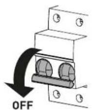
7.2 External cleaning
7.2.1 Cleaning the case
When cleaning the cladding, use a cloth dampened with soap and water or alcohol for stubborn marks.

PROHIBITION
Do not use abrasive products.
7.3 Burner Inspection
7.3.1 Burner access
To access the internal parts of the boiler:
- open the two catches (1), unscrew the two screws (2), pull the front panel (3) forwards and release it from the top by lifting it

- remove the screws (4) securing the control panel (5)
- move the panel (5) upwards (a) but keeping it in the side guides (6) to the end of travel
- bring it forwards and down (b) until it is horizontal

- remove the two screws (7), lift the expansion vessel and hook it onto the support (8)

- loosen the clip (9) and extract the air inlet pipe (10)
- unscrew the swivel joint (11)
- extract the connectors (12) from the fan and disconnect the electrode cable (13)

- Unscrew the four nuts (14) securing the combustion chamber door (15)
- pull the fan/sleeve/door/air pipe assembly (16) forwards and remove it.


CAUTION
Work carefully when removing the assembly (16) to prevent any damage occurring to the internal insulation of the combustion chamber and the door seal.
7.3.2 Cleaning the burner and the combustion chamber
The combustion chamber and the burner do not require any particular maintenance. Simply brush them with a soft brush.
7.3.3 Checking the ignition/detection electrode
Check the state of the ignition/detection electrode and replace if necessary. Check the measurements as per the drawing whether the ignition/detection electrode is replaced or not.

7.3.4 Cleaning the smoke exchanger
Remove the cover (17) by unscrewing the two screws and remove any carbon deposits.
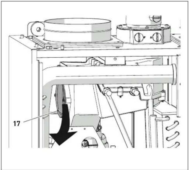
natural_image
Technical line drawing of a mechanical device with labeled component '17' and directional arrow (no readable text or symbols)7.3.5 Final operations
After having cleaned the combustion chamber and the burner:
- remove any carbon residue
- check that the seal and the insulation of the door (15) to the combustion chamber are undamaged. Replace if necessary
- refit the assembly by carrying out the same operations for removal but in the reverse order and tighten the screws (14) of the door to the combustion chamber
- reconnect the air duct and tighten the clips
- reconnect the connections to the fan and the electrode
- refit the expansion vessel in its original position.
7.3.6 Cleaning the heat pump
The only maintenance work required on the heat pump is cleaning of the evaporator with a suitable tool (a form of brush).
7.4 Checks
7.4.1 Checking the flue
Check that the combustion air inlet/outlet ducts and smoke outlet duct are integral and airtight.
7.4.2 Checking the expansion vessel pressure
It is recommended that the expansion vessel on the water side is drained and that the prefilling pressure is not less than 1 bar. If this is not the case, pressurize it to the correct value (see section "Expansion vessel").
Once the checks described above have been completed:
- refill the boiler as described in section "SYSTEM Filling"
– check that the siphon has been filled correctly - start the boiler, complete fully the Chimney sweep function" phase, described in the relevant paragraph, and perform the flue gas analysis and/or the combustion performance measurement
- refit the front panel, fixing it in place with the two catches (1).
7.5 Circuit Board Replacement
Should the circuit board be replace, the engineer MUST set the parameters as indicated in this table and in the sequence shown.
| Type No. | Description | Setting for Murelle Revolution 30 |
| PAR 01 | Index showing boiler power in kW6 = 30 (MURELLE REVOLUTION 30) | |
| PAR 02 | Hydraulic configuration0 = combi1 = system2 = N/A3 = N/A4=instant with solar power input | |
| PAR 03 | Gas Type Configuration0 = G20; 1 = G31 |
To enter "Parameter setting and display" refer to the indications provided in the specific section.
Once the parameters in the table have been set, you must carry out the entire phase of "Automatic self-calibrating procedure" described in the specific section.
If the gas valve and/or the ignition/detection electrode, and/or the burner, and/or the fan are replaced, the engineer must still carry out the entire phase of "Automatic self-calibrating procedure" described in the specific section.
7.6 Malfunction codes and possible solutions Boiler fault (gas side)
| Type No. Fault Solution | |||
| ALL 01 | Not used - | ||
| ALL 02 | Low water pressure in system | - Restore pressure- Check for any leaks in the system | |
| ALL 03 | High water pressure in system | - Empty the system via the drain valve on the hydraulic assembly and bring the pressure to approximately 1.2 bar | |
| ALL 04 | Domestic hot water sensor (SS) fault | - Check connections- Check the sensor is working | |
| ALL 05 | Delivery sensor fault | - Check connections- Check the sensor is working | |
| ALL 06 | No flame detection | - Check the integrity of the electrode and check that it is not grounded- Check gas availability and pressure- Check the operation of the gas valve- Clean and check the integrity of the mesh filter on the pressure point of the gas valve installed in the lower part of the boiler. If necessary, replace the mesh filter (see specific paragraph) | |
| ALL 07 | Safety thermostat intervention | - Check the sensor or thermostat connections- Deaerate the system- Check the bleed valve- Replace the sensor or the thermostat- Check that the pump impeller is not blocked | |
| ALL 08 | Fault in the flame detection circuit | - Check the integrity of the electrode and check that it is not grounded- Check gas availability and pressure- Check the operation of the gas valve | |
| Type No. Fault Solution | ||
| ALL 09 | No water circulating in the system- Check the rotation of the pump rotor- Check the electrical connections- Replace the pump | |
| ALL 10 | Auxiliary sensor fault- Check PAR 02 "hydraulic configuration"- Check the electrical connection | |
| ALL 11 | Gas valve modulator disconnected- Check the electrical connection | |
| ALL 12 | Incorrect configuration of the open / sealed chamber- Set the parameter PAR 04 (Combustion configuration) to 0 | |
| ALL 13 | Exhaust sensor intervention- Replace the smoke probe- Contact the Technical Assistance Centre | |
| ALL 14 | Exhaust sensor fault- Replace the smoke probe- Check the electrical connection of the smoke probe, if the problem is not resolved, contact the Assistance Centre | |
| ALL 15 | Fan check cable disconnected- Check the connection cable between the fan and the board | |
| ALL 18 | Condensate level fault- Check for any clogging in the pipe which takes the condensate to the siphon- Check that the siphon is not clogged | |
| ALL 28 | Maximum number of consecutive resets reached (6)- Wait 1 hour and try unblocking the board again- Contact the Technical Assistance Centre | |
| ALL 30 | Return sensor (SR) fault- Replace the return probe- Check parameters- Contact the Technical Assistance Centre | |
| ALL 37 | Fault due to low network voltage- Check the voltage- Contact your network provider | |
| ALL 40 | Incorrect supply frequency detected- Contact your network provider | |
| ALL 41 | Flame loss more than 6 consecutive times- Check the ignition/detection electrode- Check the gas supply (open valve)- Check mains gas pressure | |
| ALL 42 Button fault - Check that buttons are working | ||
| ALL 43 | Open Therm communication fault- Check the OT electric connection | |
| ALL 44 | Gas valve timeout fault without flame- Check for the presence of water hammer on the hot water system and, if present, mount a water hammer arrestor- Check for any abnormal requests on the room thermostat- Contact the Technical Assistance Centre | |
| ALL 62 | Self-calibrating procedure is required- Carry out the self-calibrating procedure (see the specific section) | |
| ALL 72 | Incorrect positioning of the delivery sensor- Check delivery sensor operation and position | |
| ALL 77 | EV2 SGV current max/min absolute limits error- Check gas valve and board | |
| ALL 78 | EV2 SGV current upper limit error- Check gas valve and board | |
| ALL 79 | EV2 SGV current lower limit error- Check gas valve and board | |
| ALL 80 | Fault on the valve control logic line/valve cable damaged- Check gas valve and board | |
| ALL 82 | Block due to numerous combustion control failures- Check electrode- Check outlets | |
| Type No. Fault Solution | |||
| ALL 84 | Flow rate reduced for (presumed) low pressure on mains gas | - Check gas flow rate | |
| ALL 88 | Internal error (board component protection) | - Check the board is working- Replace board | |
| ALL 89 | Unstable combustion feedback signal error | - Check electrode- Check outlets- Check air diaphragm (for BF models)- Check gas calibration | |
| ALL 90 | Combustion set cannot be reached error | - Check electrode- Check outlets- Check air diaphragm (for BF models)- Check gas calibration | |
| ALL 91 | Gas valve out of range | - Recalibrate the gas valve | |
| ALL 92 | System has reached maximum air correction error (at the minimum flow rate) | - Check electrode- Check outlets- Check air diaphragm (for BF models)- Check gas calibration | |
| ALL 93 | Combustion set cannot be reached error | - Check electrode- Check outlets- Check air diaphragm (for BF models)- Check gas calibration | |
| ALL 95 | Flame signal micro interruptions error | - Check electrode- Check board- Check electric power supply- Check gas calibration | |
| ALL 96 | Lockout due to flue (exhaust) blockage | - Check for blockage in flue- Check the smoke outlet and electrode position (not touching the burner) | |
| ALL 98 | SW error, board start-up | - Contact the Technical Assistance Centre | |
| ALL 99 | General board error | - Contact the Technical Assistance Centre | |
| - | - | Frequent relief valve intervention | - Check circuit pressure- Check expansion vessel |
| - | - | Limited production of domestic hot water | - Check the diverter valve- Check that plate heat exchanger is clean- Check domestic hot water circuit valve |
Heat pump fault
| Type No. | Description Solution | ||
| P 02 | High pressure | Automatic resetRemove and reconnect the electrical power supply | |
| P 04 | Low pressure | Automatic resetRemove and reconnect the electrical power supply | |
| P 12 | Antifreeze (heat exchanger temp. < 3°C) | Wait for heat exchanger temp. > 5°C | |
| P 15 | High temperature (HP delivery temp. > 50°C) | Automatic restore when delivery temp. < 48°C | |
| P 32 | Probe errors aggregate (one or more probes with an active alarm) | Automatic restore after sensor replaced | |
| P 33 | Battery temperature probe error | Replace the damaged probe | |
| P 34 | Inlet water temperature probe error | Replace the damaged probe | |
| P 35 | Outlet water temperature probe error | Replace the damaged probe | |
8 MURELLE REVOLUTION CHECKLIST 30
The Murelle Revolution boiler must be installed and commissioned solely by qualified companies or by professionally qualified technicians as specified in the appliance manual.
INSTALLATION
| N°Description | √ | |
| 1 | Read the appliance manual supplied. | |
| 2 | Check that the installation location/room and chosen wall are suitable for the appliance type and weight. | |
| 3 | Use the template provided with the appliance to prepare the plumbing, fuel, air inlet/outlet ducts, and smoke outlet ducts. | |
| 4 | Attach the anti-vibration supports and spacers to the back of the appliance. | |
| 5 | Mount the appliance on the wall. | |
| 6 | Wash and treat the water system before connecting up the plumbing and gas. | |
| 7 | Connect up the plumbing, gas supply and condensate outlet.Fit a filter to the system return pipe. | |
| 8 | Check that the smoke system load loss falls within the limits as per the manual, then prepare and mount the air inlet and outlet ducts and the smoke outlet duct. | |
| 9 | Connect up the electrics to the grid, main control panel, thermostat(s) for the zones, and outdoor probe. | |
| 10 | Open the gas mains and check the seal of the joints. Then shut off the gas supply. | |
| 11 | Check the water characteristics, then fill to 1-1.2 bar pressure. | |
| 12 | De-aerate the systems. | |
COMMISSIONING
| N°Description | √ | |
| 13 | Open the water system isolation valves and the gas valve and power the appliance. | |
| 14 | Select “Summer” mode on the main control panel. | |
| 15 | Disconnect and reconnect the power using the main switch. | |
| 16 | Auto-calibrate the boiler from the boiler control panel. Check that the boiler (gas side) produces hot water correctly, and check also that the gas line load loss at maximum power falls within the standard values (see standard UNI 7129). | |
| 17 | Select “Winter” mode and activate the system via the remote control. | |
| 18 | Check that Murelle Revolution operates correctly in HP + Boiler mode; where necessary, check the function status/-specific set points via the technical menu (see instruction manual). | |
| 19 | Activate the “Chimney sweep” function and check the data and combustion performance. | |
| 20 | Check that the delivery limit temperature is compatible with the type of system: the factory setting is 65°C. | |
The installer declares that the appliance (serial no. .......) has been installed, commissioned and checked in line with the manufacturer's instructions and the laws in force in the country where the appliance will be used.
Stamp and signature
ANNEXES
PRODUCT DATA SHEETMURELLE REVOLUTION 30
 | |
| MURELLE REVOLUTION 30 | |
| Seasonal energy efficiency of heating from heat pump [“I”] (%) | 155 |
| Temperature control contribution (%) | 4 |
| Additional boiler contribution (%) | -25 |
| Solar energy contribution (%) | 0 |
| Energy efficiency class of combined central heating |  |
| Seasonal energy efficiency of combined central heating (%) | 134 |
| Weighting factor of preferential heating appliance heat output [“II”] | 0,403 |
| Result of mathematical expression 294/(11*Pnominal) [“III”] | 6,68 |
| Result of mathematical expression 115/(11*Pnominal) [“IV”] | 2,61 |
| Energy efficiency of combi boiler for DHW (%) | 84 |
| D.H.W load profile declared | XL |
| Solar energy contribution (%) | - |
| Energy efficiency class of combined DHW |  |
| Energy efficiency of combined DHW in average climatic conditions (%) | 84 |
| Result of mathematical expression (220*Qref)/Qnonsol [“II”] | - |
| Result of mathematical expression (Qaux*2,5)/(220*Qref) [“III”] | - |
| Conforming to Annex IV (item 6) of the Delegated Regulations (EU) No. 811/2013 which supplements Directive 2010/30/EU | |
Benchmark Commissioning & Warranty Validation Service Record
It is a requirement that the boiler is installed and commissioned to the manufacturers' instructions and the data fields on the commissioning checklist completed in full.
To instigate the boiler warranty the boiler needs to be registered with the manufacturer within one month of the installation. The warranty rests with the end-user (consumer), and they should be made aware it is ultimately their responsibility to register with the manufacturer, within the allotted time period.
It is essential that the boiler is serviced in line with the manufacturers' recommendations, at least annually. This must be carried out by a competent Gas Safe registered engineer. The service details should be recorded on the Benchmark Service and Interim Boiler Work Record and left with the householder. Failure to comply with the manufacturers' servicing instructions and requirements will invalidate the warranty.

www.hhic.co.uk
This Commissioning Checklist is to be completed in full by the competent person who commissioned the boiler as a means of demonstrating compliance with the appropriate Building Regulations and then handed to the customer to keep for future reference.
Failure to install and commission according to the manufacturers' instructions and complete this Benchmark Commissioning Checklist will invalidate the warranty. This does not affect the customer's statutory rights.
* All installations in England and Wales must be notified to Local Authority Building Control (LABC) either directly or through a Competent Persons Scheme. A Building Regulations Compliance Certificate will then be issued to the customer.
© Heating and Hotwater Industry Council (HHIC)

www.centralheating.co.uk
GAS BOILER SYSTEM COMMISSIONING CHECKLIST & WARRANTY VALIDATION RECORD
| Address: | |||||||||||||||||||||
| Boiler make and model: | |||||||||||||||||||||
| Boiler serial number: | |||||||||||||||||||||
| Commissioned by (PRINT NAME): Gas Safe registration number: | |||||||||||||||||||||
| Company name: Telephone number: | |||||||||||||||||||||
| Company email: Company address: | |||||||||||||||||||||
| Commissioning date: | |||||||||||||||||||||
| Heating and hot water system complies with the appropriate Building Regulations? Yes | |||||||||||||||||||||
| Optional: Building Regulations Notification Number (if applicable): | |||||||||||||||||||||
| Time, temperature control and boiler interlock provided for central heating and hot water Yes | |||||||||||||||||||||
| Boiler Plus requirements (tick the appropriate box(s)) | |||||||||||||||||||||
| Boiler Plus option chosen for combination boiler in ENGLAND | Weather compensation Smart thermostat with automisation and optimisation | ||||||||||||||||||||
| Load compensation Flue Gas Heat Recovery | |||||||||||||||||||||
| Time and temperature control to hot water Cylinder thermostat and programmer/timer Combination boiler | |||||||||||||||||||||
| Zone valves pre-existing Fitted Not required | |||||||||||||||||||||
| Thermostatic radiator valves pre-existing Fitted Not required | |||||||||||||||||||||
| Automatic bypass to system pre-existing Fitted Not required | |||||||||||||||||||||
| Underfloor heating | pre-existing Fitted Not required | ||||||||||||||||||||
| Water quality | |||||||||||||||||||||
| The system has been flushed, cleaned and a suitable inhibitor applied upon final fill, in accordance with BS7593 and boiler manufacturers' instructions Yes | |||||||||||||||||||||
| What system cleaner was used? | Brand: | Product: | |||||||||||||||||||
| What inhibitor was used? | Brand: | Product: | |||||||||||||||||||
| Primary water system filter | pre-existing Fitted Not required | ||||||||||||||||||||
| CENTRAL HEATING MODE measure and record (as appropriate) | |||||||||||||||||||||
| Gas rate (for combination boilers complete DHW mode gas rate) | m³hr | or | ft3/hr | ||||||||||||||||||
| Central heating output left at factory settings? | Yes | No | |||||||||||||||||||
| If no. what is the maximum central heating output selected? | kW | ||||||||||||||||||||
| Dynamic gas inlet pressure | mbar | ||||||||||||||||||||
| Central heating flow temperature | ℃ | ||||||||||||||||||||
| Central heating return temperature | ℃ | ||||||||||||||||||||
| System correctly balanced/rebalanced? Yes | |||||||||||||||||||||
| COMBINATION BOILERS ONLY | |||||||||||||||||||||
| Is the installation in a hard water area (above 200ppm)? | Yes | No | |||||||||||||||||||
| Water scale reducer/softener pre-existing | Fitted | ||||||||||||||||||||
| What type of scale reducer/softener has been fitted? | Brand: | Product: | |||||||||||||||||||
| Water meter fitted? | Yes | No | |||||||||||||||||||
| If yes- DHW expansion vessel | pre-existing | Fitted | Not required | ||||||||||||||||||
| Pressure reducing valve | pre-existing | Fitted | Not required | ||||||||||||||||||
| DOMESTIC HOT WATER MODE Measure and record | |||||||||||||||||||||
| Gas rate | m³hr | or | ft3/hr | ||||||||||||||||||
| Dynamic gas inlet pressure at maximum rate mbar | |||||||||||||||||||||
| Cold water inlet temperature ℃ | |||||||||||||||||||||
| Hot water has been checked at all outlets Yes Temperature ℃ | Yes | Temperature ℃ | ℃ | ||||||||||||||||||
| CONDENSATE DISPOSAL | |||||||||||||||||||||
| The condensate drain has been installed in accordance with the manufacturers' instructions and/or BS5546/BS6798 Yes Yes | |||||||||||||||||||||
| Point of termination Internal External (only where internal termination impractical) | |||||||||||||||||||||
| Method of disposal Gravity Pumped | Gravity | ||||||||||||||||||||
| ALL INSTALLATIONS | |||||||||||||||||||||
| Record the following | At max rate: | CO ppm | CO2 % CO/CO2 Ratio | CO/CO2 % CO/CO2 Ratio | |||||||||||||||||
| At min rate (where possible) | CO ppm | CO2 % CO/CO2 Ratio | |||||||||||||||||||
| Where possible, has a flue integrity check been undertaken in accordance with manufacturers' instructions, and readings are correct? Yes | Yes | ||||||||||||||||||||
| The operation of the boiler and system controls have been demonstrated to and understood by the customer Yes | Yes | ||||||||||||||||||||
| The manufacturers' literature, including Benchmark Checklist and Service Record, has been explained and left with the customer Yes | Yes | ||||||||||||||||||||
| Commissioning Engineer's signature | |||||||||||||||||||||
| Customer's signature(To confirm satisfactory demonstration and receipt of manufacturers' literature) | |||||||||||||||||||||
* All installations in England and Wales must be notified to Local Authority Building Control (LABC) either directly or through a Competent Persons Scheme. A Building Regulations Compliance Certificate will then be issued to the customer.
© Heating and Hotwater Industry Council (HHIC)

www.centralheating.co.uk
SERVICE & INTERIM BOILER WORK RECORD
It is recommended that your boiler and heating system are regularly serviced and maintained, in line with manufacturers' instructions, and that the appropriate service / interim work record is completed.
Service provider
When completing a service record (as below), please ensure you have carried out the service as described in the manufacturers' instructions. Always use the manufacturers' specified spare parts.
| SERVICE/INTERIM WORK ON BOILER delete as appropriate | Date: | ||||
| Engineer name: Company name: | |||||
| Telephone N: Gas Safe registration N " : | |||||
| Max rate CO ppm CO 2 % CO/CO 2 | |||||
| Min rate CO ppm CO 2 % CO/CO 2 | |||||
| Where possible, has a flue integrity check been undertaken in accordance with manufacturers' instructions, and readings are correct?" | yes | ||||
| Gas rate: m | 3/h OR ft | 5/h | |||
| Were parts fitted? delete as appropriate Yes No | |||||
| Parts fitted: | |||||
| System inhibitor concentration has been checked and appropriate action taken, in accordance with BS 7593 and boiler manufacturers' instructions. ^ | yes n/a | ||||
| Comments: | |||||
| Signature: | |||||
"A System inhibitor efficacy test is required on every annual service in accordance with the manufacturers' instructions and BS 7593. It is only acceptable to not have undertaken this if the service engineers attendance visit was in between annual services to attend a non-water facing component,
| SERVICE/INTERIM WORK ON BOILER delete as appropriate | Date: | ||||
| Engineer name: Company name: | |||||
| Telephone N°: Gas Safe registration N | c: | ||||
| Max rate CO ppm CO 2 % CO/CO 2 | |||||
| Min rate CO ppm CO 2 % CO/CO 2 | |||||
| Where possible, has a flue integrity check been undertaken in accordance with manufacturers' instructions, and readings are correct?" | yes | ||||
| Gas rate: m | 3/h OR ft | 3/h | |||
| Were parts fitted? delete as appropriate Yes No | |||||
| Parts fitted: | |||||
| System inhibitor concentration has been checked and appropriate action taken, in accordance with BS 7593 and boiler manufacturers' instructions. ^ | yes n/a | ||||
| Comments: | |||||
| Signature: | |||||
*A System inhibitor efficacy test is required on every annual service in accordance with the manufacturers' instructions and BS 7593. It is only acceptable to not have undertaken this if the service engineers attendance visit was in between annual services to attend a non-water facing component.
| SERVICE/INTERIM WORK ON BOILER delete as appropriate | Date: | ||||
| Engineer name: Company name: | |||||
| Telephone N°: Gas Safe registration N % | |||||
| Max rate CO ppm CO 2 % CO/CO 2 | |||||
| Min rate CO ppm CO 2 % CO/CO 2 | |||||
| Where possible, has a flue integrity check been undertaken in accordance with manufacturers' instructions, and readings are correct?" | yes | ||||
| Gas rate: m | ?h OR ft | %h | |||
| Were parts fitted?delete as appropriate Yes No | |||||
| Parts fitted: | |||||
| System inhibitor concentration has been checked and appropriate action taken, in accordance with BS 7593 and boiler manufacturers' instructions. * | yes n/a | ||||
| Comments: | |||||
| Signature: | |||||
*A System inhibitor efficacy test is required on every annual service in accordance with the manufacturers' instructions and BS 7593. It is only acceptable to not have undertaken this if the service engineers attendance visit was in between annual services to attend a non-water facing component.
| SERVICE/INTERIM WORK ON BOILER delete as appropriate | Date: | ||||
| Engineer name: Company name: | |||||
| Telephone N°: Gas Safe registration N | " : | ||||
| Max rate CO ppm CO | 2 | % | CO/CO 2 | ||
| Min rate CO ppm CO | 2 | % | CO/CO 2 | ||
| Where possible, has a flue integrity check been undertaken in accordance with manufacturers' instructions, and readings are correct?" | yes | ||||
| Gas rate: m | 3/h OR ft | 3/h | |||
| Were parts fitted?delete as appropriate Yes No | |||||
| Parts fitted: | |||||
| System inhibitor concentration has been checked and appropriate action taken, in accordance with BS 7593 and boiler manufacturers' instructions. ^ | yes n/a | ||||
| Comments: | |||||
| Signature: | |||||
"A System inhibitor efficacy test is required on every annual service in accordance with the manufacturers' instructions and BS 7593. It is only acceptable to not have undertaken this if the service engineers attendance visit was in between annual services to attend a non-water facing component.
| SERVICE/INTERIM WORK ON BOILER delete as appropriate | Date: | ||||
| Engineer name: Company name: | |||||
| Telephone N°: Gas Safe registration N | |||||
| Max rate CO ppm CO 2 % CO/CO 2 | |||||
| Min rate CO ppm CO 2 % CO/CO 2 | |||||
| Where possible, has a flue integrity check been undertaken in accordance with manufacturers' instructions, and readings are correct?" | yes | ||||
| Gas rate: m | 3/h OR ft | 3/h | |||
| Were parts fitted?delete as appropriate Yes No | |||||
| Parts fitted: | |||||
| System inhibitor concentration has been checked and appropriate action taken, in accordance with BS 7593 and boiler manufacturers' instructions. * | yes n/a | ||||
| Comments: | |||||
| Signature: | |||||
*A System inhibitor efficacy test is required on every annual service in accordance with the manufacturers' instructions and BS 7593. It is only acceptable to not have undertaken this if the service engineers attendance visit was in between annual services to attend a non-water facing component.
| SERVICE/INTERIM WORK ON BOILER device as appropriate | Date: | ||||
| Engineer name: Company name: | |||||
| Telephone N2: Gas Safe registration N | c: | ||||
| Max rate CO ppm CO | 2 | % CO/CO 2 | |||
| Min rate CO ppm CO | 2 | % CO/CO 2 | |||
| Where possible, has a flue integrity check been undertaken in accordance with manufacturers' instructions, and readings are correct?" | yes | ||||
| Gas rate: m | 3/h OR ft | 3/h | |||
| Were parts fitted?delete as appropriate Yes No | |||||
| Parts fitted: | |||||
| System inhibitor concentration has been checked and appropriate action taken, in accordance with BS 7593 and boiler manufacturers' instructions. * | yes n/a | ||||
| Comments: | |||||
| Signature: | |||||
*A System inhibitor efficacy test is required on every annual service in accordance with the manufacturers' instructions and BS 7593. It is only acceptable to not have undertaken this if the service engineers attendance visit was in between annual services to attend a non-water facing component.
* All installations in England and Wales must be notified to Local Authority Building Control (LABC) either directly or through a Competent Persons Scheme. A Building Regulations Compliance Certificate will then be issued to the customer.
© Heating and Hotwater Industry Council (HHIC)

www.centralheating.co.uk
SERVICE & INTERIM BOILER WORK RECORD
It is recommended that your boiler and heating system are regularly serviced and maintained, in line with manufacturers' instructions, and that the appropriate service / interim work record is completed.
Service provider
When completing a service record (as below), please ensure you have carried out the service as described in the manufacturers' instructions. Always use the manufacturers specified spare parts.
| SERVICE/INTERIM WORK ON BOILER delete as appropriate | Date: | ||||
| Engineer name: Company name: | |||||
| Telephone N: Gas Safe registration N " : | |||||
| Max rate CO ppm CO 2 % CO/CO 2 | |||||
| Min rate CO ppm CO 2 % CO/CO 2 | |||||
| Where possible, has a flue integrity check been undertaken in accordance with manufacturers' instructions, and readings are correct?" | yes | ||||
| Gas rate: m | 3/h OR ft | 5/h | |||
| Were parts fitted?delete as appropriate Yes No | |||||
| Parts fitted: | |||||
| System inhibitor concentration has been checked and appropriate action taken, in accordance with BS 7593 and boiler manufacturers' instructions. ^ | yes n/a | ||||
| Comments: | |||||
| Signature: | |||||
*A System inhibitor efficacy test is required on every annual service in accordance with the manufacturers' instructions and BS 7593. It is only acceptable to not have undertaken this if the service engineers attendance visit was in between annual services to attend a non-water facing component.
| SERVICE/INTERIM WORK ON BOILER delete as appropriate | Date: | |||||
| Engineer name: Company name: | ||||||
| Telephone N°: Gas Safe registration N | 6: | |||||
| Max rate CO ppm CO 2 % CO/CO 2 | ||||||
| Min rate CO ppm CO 2 % CO/CO 2 | ||||||
| Where possible, has a flue integrity check been undertaken in accordance with manufacturers' instructions, and readings are correct?" | yes | |||||
| Gas rate: m | 3/h OR ft | 3/h | ||||
| Were parts fitted? delete as appropriate Yes No | ||||||
| Parts fitted: | ||||||
| System inhibitor concentration has been checked and appropriate action taken, in accordance with BS 7593 and boiler manufacturers' instructions.4 | yes n/a | |||||
| Comments: | ||||||
| Signature: | ||||||
*A System inhibitor efficacy test is required on every annual service in accordance with the manufacturers' instructions and BS 7593. It is only acceptable to not have undertaken this if the service engineers attendance visit was in between annual services to attend a non-water facing component.
| SERVICE/INTERIM WORK ON BOILER delete as appropriate | Date: | ||||
| Engineer name: Company name: | |||||
| Telephone N°: Gas Safe registration N % | |||||
| Max rate CO ppm CO | 2 % CO/CO 2 | ||||
| Min rate CO ppm CO | 2 % CO/CO 2 | ||||
| Where possible, has a flue integrity check been undertaken in accordance with manufacturers' instructions, and readings are correct?" | yes | ||||
| Gas rate: m | 3h OR ft | 5/h | |||
| Were parts fitted?delete as appropriate Yes No | |||||
| Parts fitted: | |||||
| System inhibitor concentration has been checked and appropriate action taken, in accordance with BS 7593 and boiler manufacturers' instructions.4 | yes n/a | ||||
| Comments: | |||||
| Signature: | |||||
*A System inhibitor efficacy test is required on every annual service in accordance with the manufacturers' instructions and BS 7593. It is only acceptable to not have undertaken this if the service engineers attendance visit was in between annual services to attend a non-water facing component.
| SERVICE/INTERIM WORK ON BOILER delete as appropriate | Date: | ||||
| Engineer name: Company name: | |||||
| Telephone N°: Gas Safe registration N | °: | ||||
| Max rate CO ppm CO | 2 | % CO/CO 2 | |||
| Min rate CO ppm CO | 2 | % CO/CO 2 | |||
| Where possible, has a flue integrity check been undertaken in accordance with manufacturers' instructions, and readings are correct?" | yes | ||||
| Gas rate: m | 3/h OR ft | 3/h | |||
| Were parts fitted?delete as appropriate Yes No | |||||
| Parts fitted: | |||||
| System inhibitor concentration has been checked and appropriate action taken; in accordance with BS 7593 and boiler manufacturers' instructions. | yes n/a | ||||
| Comments: | |||||
| Signature: | |||||
*A System inhibitor efficacy test is required on every annual service in accordance with the manufacturers' instructions and BS 7593. It is only acceptable to not have undertaken this if the service engineers attendance visit was in between annual services to attend a non-water facing component.
| SERVICE/INTERIM WORK ON BOILER delete as appropriate | Date: | ||||
| Engineer name: Company name: | |||||
| Telephone N°: Gas Safe registration N | |||||
| Max rate CO ppm CO 2 % CO/CO 2 | |||||
| Min rate CO ppm CO 2 % CO/CO 2 | |||||
| Where possible, has a flue integrity check been undertaken in accordance with manufacturers' instructions, and readings are correct?" | yes | ||||
| Gas rate: m | 3/h OR ft | 3/h | |||
| Were parts fitted?delete as appropriate Yes No | |||||
| Parts fitted: | |||||
| System inhibitor concentration has been checked and appropriate action taken, in accordance with BS 7593 and boiler manufacturers' instructions. * | yes n/a | ||||
| Comments: | |||||
| Signature: | |||||
*A System inhibitor efficacy test is required on every annual service in accordance with the manufacturers' instructions and BS 7593. It is only acceptable to not have undertaken this if the service engineers attendance visit was in between annual services to attend a non-water facing component.
| SERVICE/INTERIM WORK ON BOILER device as appropriate | Date: | |||||
| Engineer name: Company name: | ||||||
| Telephone N2: Gas Safe registration N °: | ||||||
| Max rate CO ppm CO | 2 | % CO/CO 2 | ||||
| Min rate CO ppm CO | 2 | % CO/CO 2 | ||||
| Where possible, has a flue integrity check been undertaken in accordance with manufacturers' instructions. and readings are correct?" | yes | |||||
| Gas rate: m | 3/h OR ft | 3/h | ||||
| Were parts fitted?delete as appropriate Yes No | ||||||
| Parts fitted: | ||||||
| System inhibitor concentration has been checked and appropriate action taken, in accordance with BS 7593 and boiler manufacturers' instructions. * | yes n/a | |||||
| Comments: | ||||||
| Signature: | ||||||
*A System inhibitor efficacy test is required on every annual service in accordance with the manufacturers' instructions and BS 7593. It is only acceptable to not have undertaken this if the service engineers attendance visit was in between annual services to attend a non-water facing component.
* All installations in England and Wales must be notified to Local Authority Building Control (LABC) either directly or through a Competent Persons Scheme. A Building Regulations Compliance Certificate will then be issued to the customer.
© Heating and Hotwater Industry Council (HHIC)

www.centralheating.co.uk
EXPLODED VIEWS
Hydronic unit (Innova)
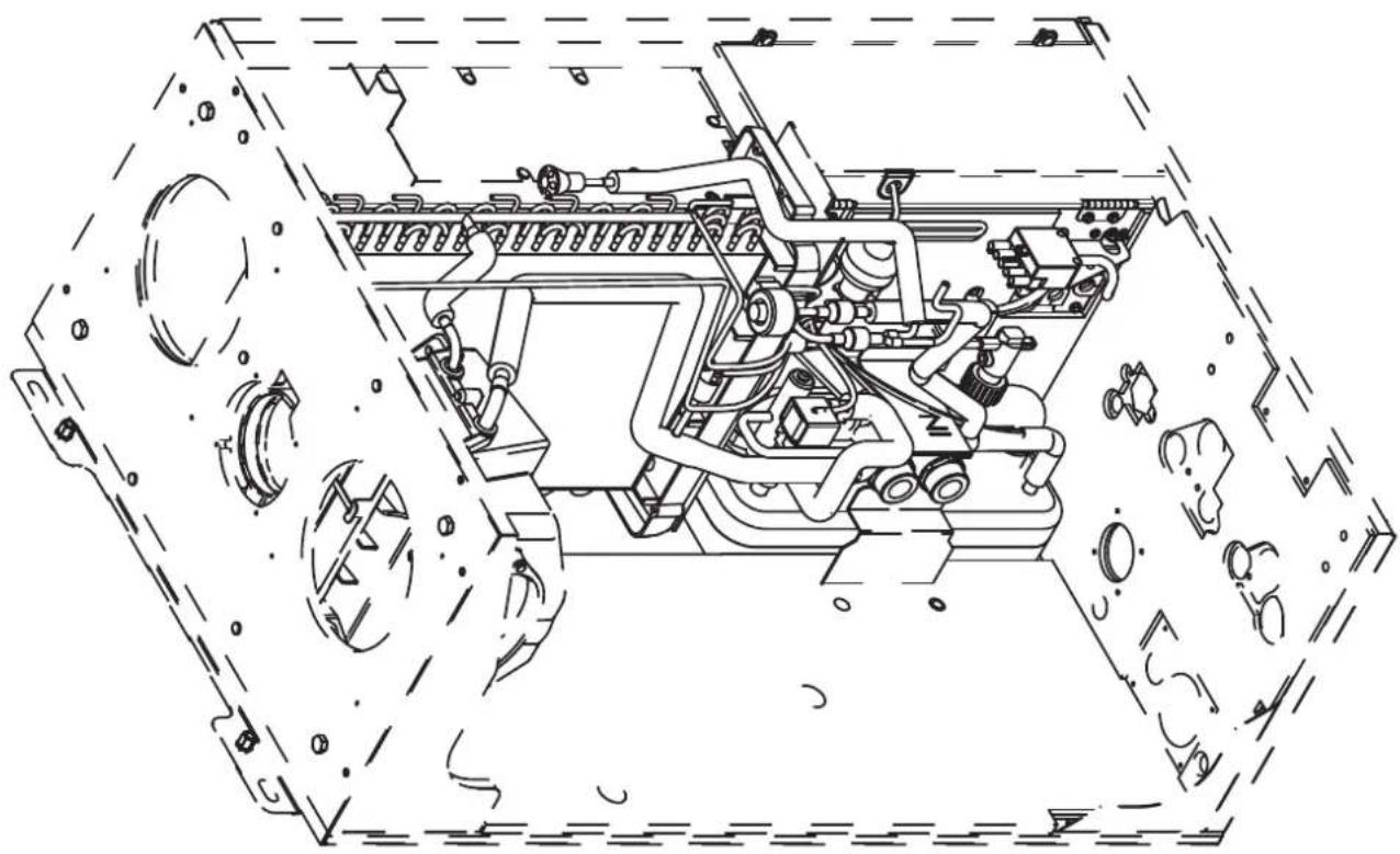
natural_image
Technical line drawing of a mechanical assembly inside a transparent housing (no text or symbols)
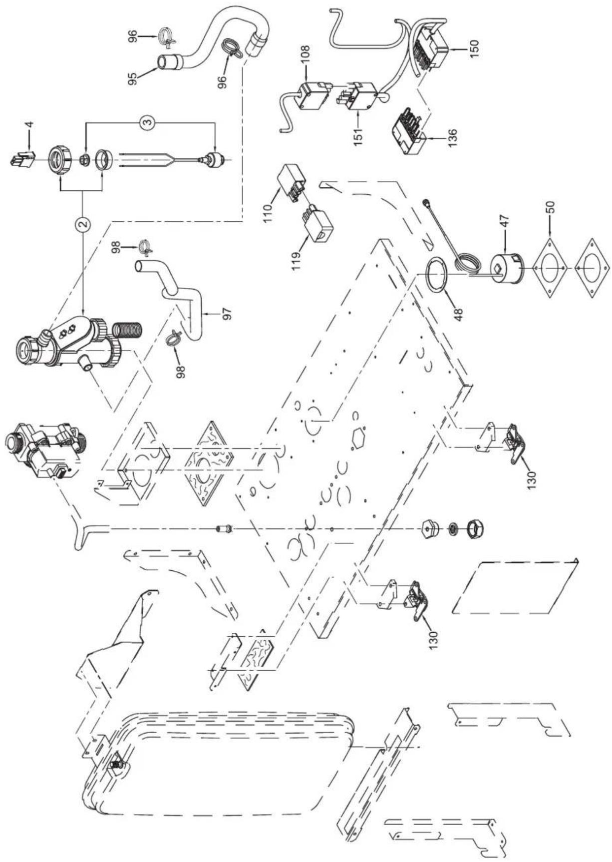
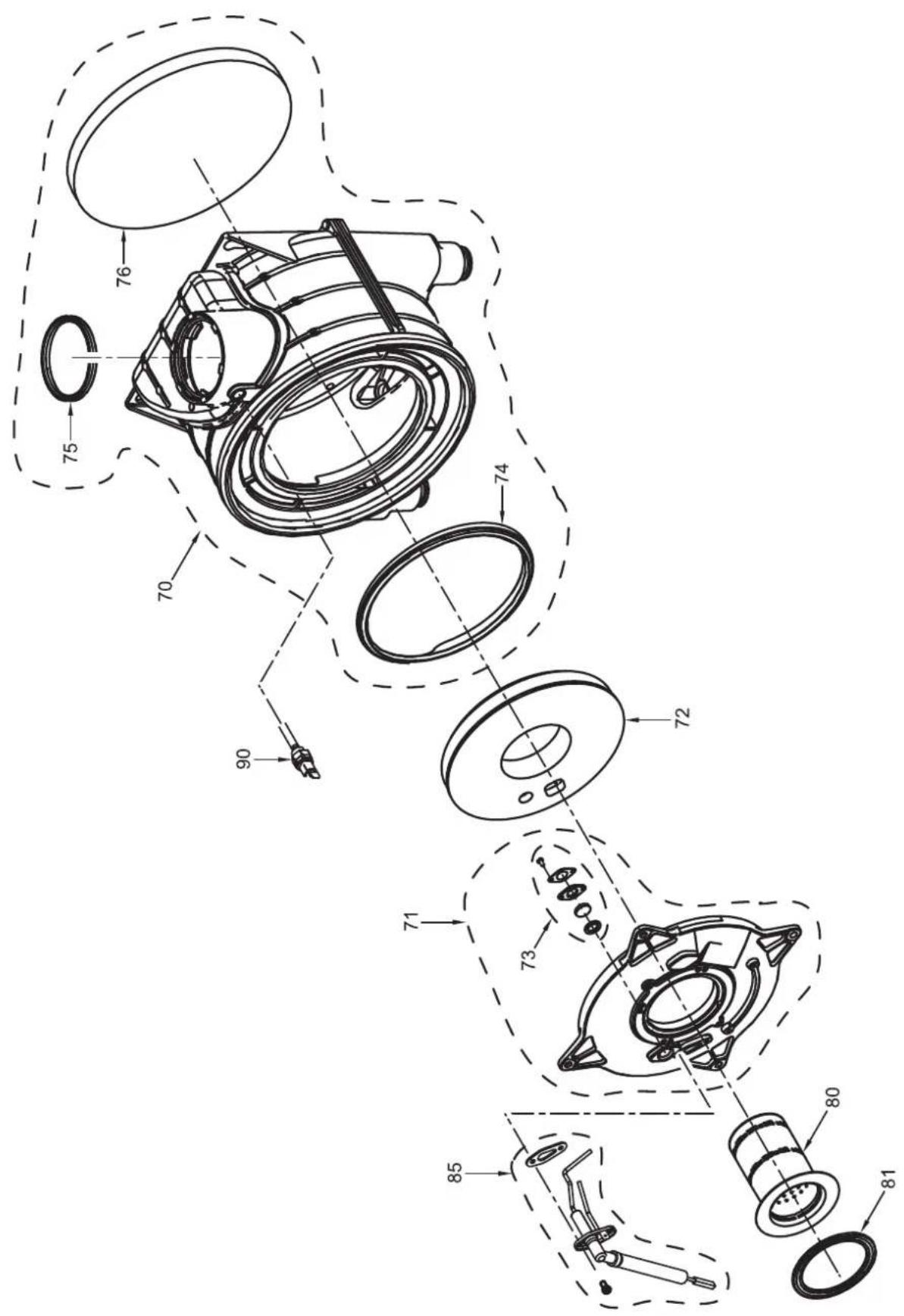

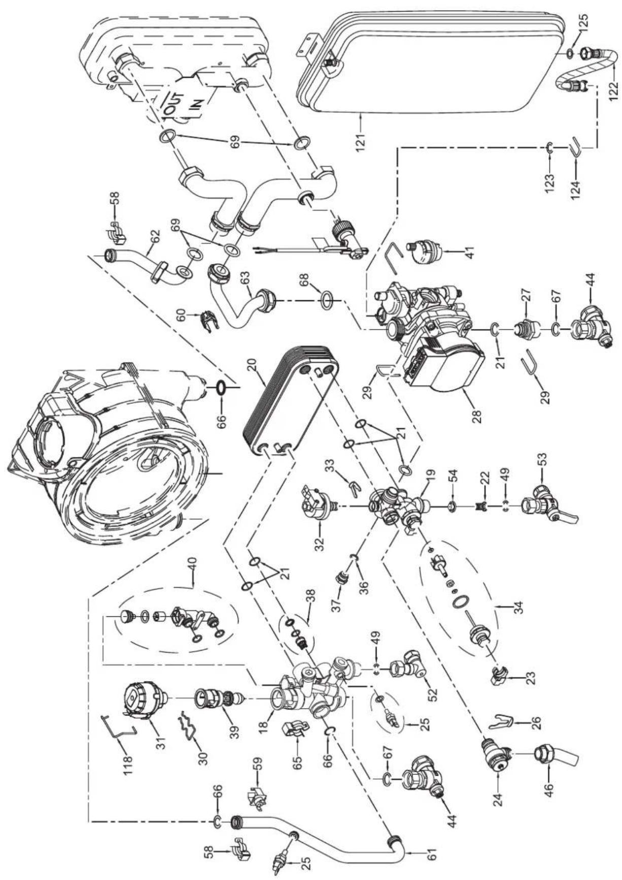
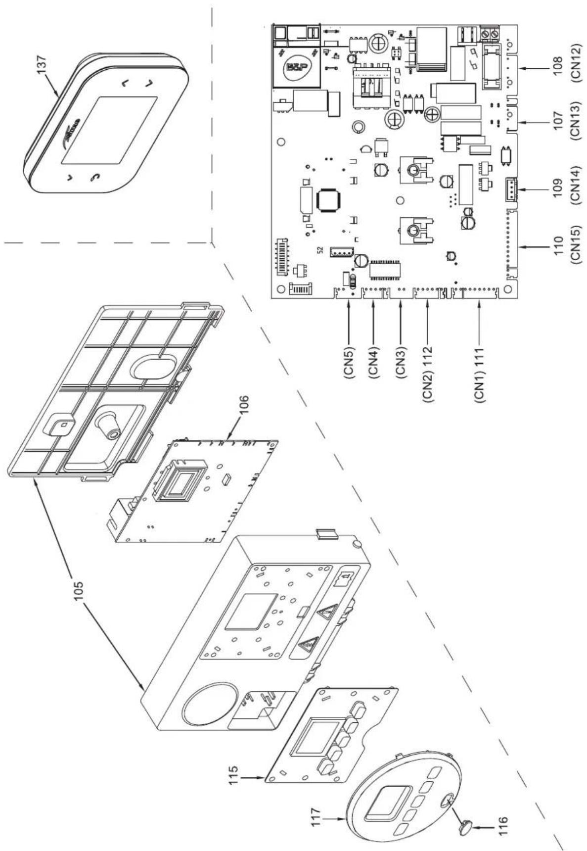
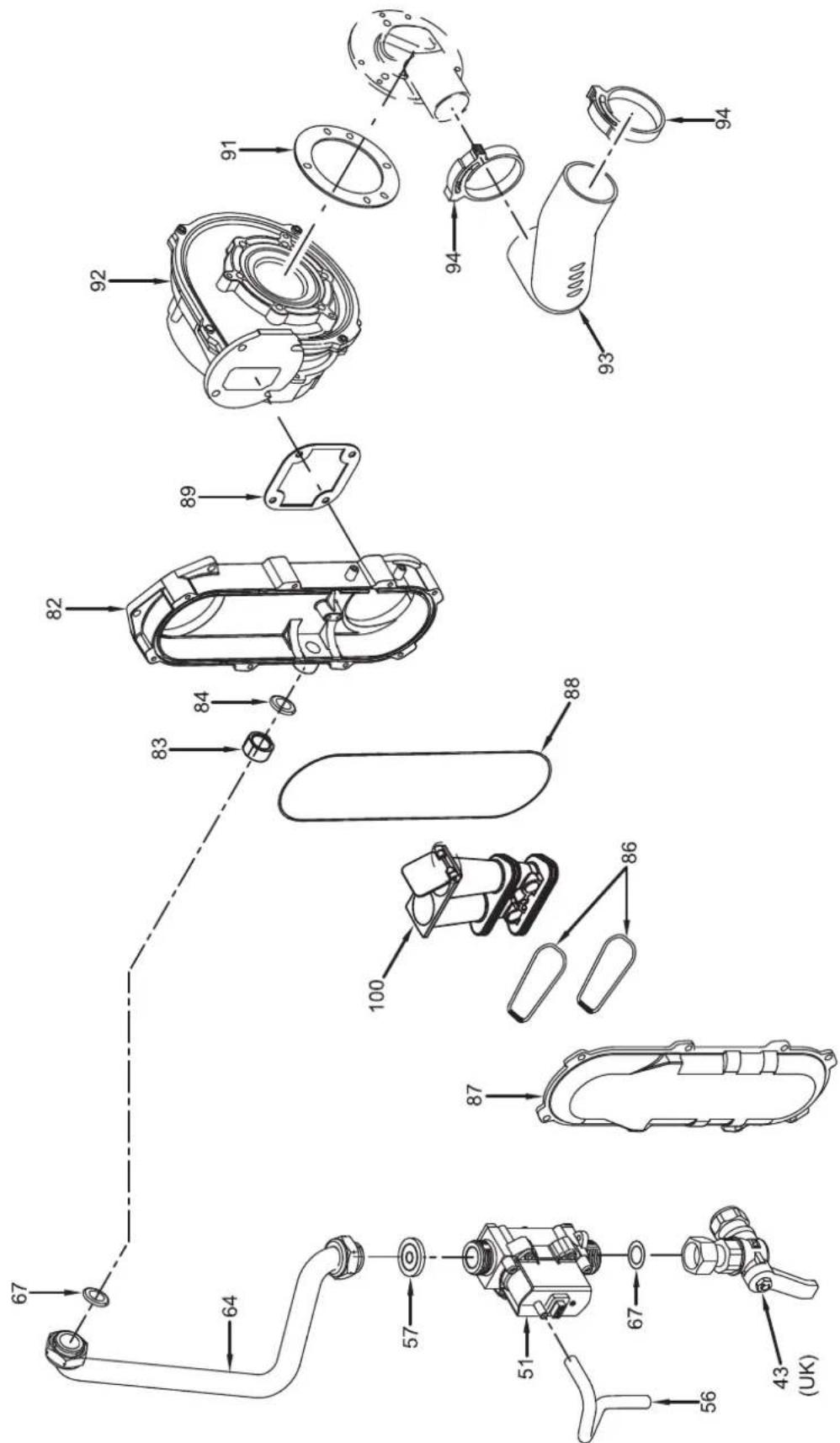
| Pos. | Code Description | Recommended spare parts |
| 001 | 6087555 Water trap insulating | |
| 002 | 6277220 Water trap | |
| 003 | 6319500 Magnetic sensor | |
| 004 | 6293560 2 pole cable connector | |
| 005 | 6287912 Air/smoke manifold | |
| 006 | 6028710 Air/smoke manifold gasket | |
| 007 | 6147409 Air/smoke manifold plug M14x1.5 | |
| 008 | 6226417 O-ring 3043 | |
| 009 | 6248817 Lip seal for ∅ 60 pipe | |
| 010 | 6083061 Flue inlet flange ∅ 80 | |
| 011 | 6028702 Gasket ∅ 95x125x2 | |
| 012 | 6083074 Air ntache adaptor d.160 | |
| 013 | 6256888 Collar fixing bracket d.160 | |
| 014 | 6028719 Neoprene sealing | |
| 015 | 6332775 Front panel kit + insulation | |
| 016 | 6332776 Left side kit + insulators | |
| 017 | 6332777 Right side kit + insulators | |
| 018 | 6265866 C.H. flow manifold | |
| 019 | 6265832 C.H. return manifold | A |
| 020 | 6319692 Kit 16 plate heat exchanger + o | |
| 021 | 6226475 ORing diam.18,64x3,53 | |
| 022 | 6222003 D.H.W. filter | |
| 023 | 6131440 Flowmeter sensor | A |
| 024 | 6040225 Pressure relief valve 1/2" 3 ba | A |
| 025 | 6281519 Plunged sensor + gasket | A |
| 026 | 6226645 Spring clip | |
| 027 | 6120560 Pump nipple 3/4" | |
| 028 | 6330466 Modulating circulating pump | |
| 029 | 6226644 Spring clip for rotating connec | |
| 030 | 6226636 D.H.W. elektrovalve fix.spring | |
| 031 | 6087332 Motor for diverting valve | A |
| 032 | 6273612 Water pressure transducer | |
| 033 | 6226639 Spring clip | |
| 034 | 6319644 Flowmeter group | A |
| 036 | 2030225 Gasket ∅ 5,5x11x2 | |
| 037 | 6147401 Plug 1/4" | |
| 038 | 6281859 Restraint valve + seeger ring | |
| 039 | 6319654 Shutter group | A |
| 040 | 6319653 External by-pass kit | A |
| 041 | 6013182 Automatic air vent | A |
| 042 | 6087593 Insulat. right side hydr. group | |
| 043 | 6177530 Gas cock 3/4" F x 15 | |
| 044 | 6177505 Ball cock 3/4" x 22 | |
| 046 | 6034130 Drain water flexible pipe | |
| 047 | 6146132 Hydrometer | |
| 048 | 6229881 Gasket | |
| 049 | 2030227 Gasket ∅ 12x18x2 | |
| 050 | 6087583 Hydrometer insulation | |
| 051 | 6243839 Gas valve | A |
| 052 | 6142330 Quarter bend 1/2" x 15 | |
| 053 | 6177506 Ball cock 1/2" x 15 | |
| 054 | 6281442 Water rate adjuster 14 l/min | |
| 056 | 1010202 Silicon pipe ∅ 8x1.5 L = 0,1 mt | |
| 057 | 6050474 Nozzle 630 met |
| Pos. | Code Description | Recommended spare parts | |
| 058 | 6226619 | Spring for heat exchanger conne | |
| 059 61 | 46729 100°C | safety stat | A |
| 060 62 | 31372 Temperature sensor | A | |
| 061 | 6277891 | C.H.W. flow pipe | |
| 062 62 | 77892 Return pipe | ||
| 063 | 6277893 | Circulat.exchanger pipe connec | |
| 064 62 | 77894 Valve gas pipe | ||
| 065 | 6226601 | Spring for heat exchanger conne | |
| 066 62 | 26412 O-ring 3068 | ||
| 067 20 | 30228 Gasket ∅ 17x24x2 | ||
| 068 20 | 30267 Piracritten gasket ∅ 30x17x2 | ||
| 069 20 | 30229 Gasket ∅ 22x30x2 | ||
| 070 62 | 78971 Heat exchanger gas-water | ||
| 071 51 | 88364 Main exchanger door | ||
| 072 62 | 69034 Insulation | ||
| 073 62 | 11794 Peephole kit + gasket | ||
| 074 63 | 26953 Sealing | ||
| 075 | 6248876 | Smoke outlet gasket ø80 mm | |
| 076 63 | 26951 Rear insulation + springs | ||
| 080 62 | 78376 Premix burner | ||
| 081 61 | 74828 Gasket for burner flange | ||
| 082 62 | 78813 Air-gas hose lower side | ||
| 083 | 6070822 | M.F. reducer 3/4"x1/2" OT | |
| 084 20 | 30255 Gasket ∅ 12,5x18,5x3 | ||
| 085 | 6281563 | Ignit.-ionis.electrode +gasket | A |
| 086 62 | 26496 O-ring 50x3.15 EP/851 | ||
| 087 62 | 78812 Air-gas hose upper side | ||
| 088 62 | 26465 O-ring ∅ 183,83x2,62 | ||
| 089 61 | 74816 Gasket for fan flange | ||
| 090 62 | 77130 Probe NTC D.4X40 | A | |
| 091 60 | 28703 Gasket for duct flange | ||
| 092 | 6261412 | Fan | A |
| 093 60 | 01184 Air intake pipe 40 | ||
| 094 20 | 51250 Hose clamp ∅ 44-47,5 | ||
| 095 60 | 34125 Condensate drainage rubber pipe | ||
| 096 20 | 51123 Clamp diam. | ||
| 097 60 | 34178 Condensate drainage rubber pipe | ||
| 098 20 | 51121 Clamp diam. 19,2 | ||
| 100 62 | 82347 Air/gas mixer assembly | ||
| 105 63 | 04720 Control panel | ||
| 106 63 | 24922 Main P.C.B. | A | |
| 107 63 | 25657 4 pole cable connector CN13 | ||
| 108 63 | 29623 6 pole cable connector CN12 | ||
| 109 63 | 23876 4 pole cable connector CN14 | ||
| 110 63 | 29621 14 pole cable connector CN15 | ||
| 111 63 | 29622 9 pole stocko conn. CN1 | ||
| 112 63 | 29458 6 pole cable connector CN2 | ||
| 115 | 6305131 Rubber button | ||
| 116 | 6305140 Rubber cap | ||
| 117 | 6304855 Interface panel | ||
| 118 | 6226638 Divertor valve motor spring cli | ||
| 119 | 6202159 4 pin plug | ||
| 121 | 5183732 Rectang. expansion vessel 9 l. | ||
| 122 | 6017407 Flex. pipe F.M.3/8"x18,65 L=500 | ||
| 123 | 6226476 ORing diam.15x2 | ||
| 124 | 6226656 Pipe fixing spring | ||
| 125 | 2030226 Gasket ∅ 10,2x14,8x2 | ||
| 126 | 6256895 Front assembly | ||
| 127 | 6087587 Casing front insulation | ||
| 128 | 1012026 Self-adhes.silic..foam profile | L = 0,57 mt | |
| 129 | 1012026 Self-adhes.silic..foam profile | L = 0,89 mt | |
| 130 | 6225802 Lever closure | ||
| 132 | 6256896 Casing right hand side panel | ||
| 133 | 6256897 Casing left hand side panel | ||
| 134 | 6087584 Side insulating right/left | ||
| 135 | 6087585 Side insulating left | ||
| 136 | 6185204 7-pin plug Wieland | ||
| 137 | 6197780 Sime SMART HR | ||
| 138 | 6133103 Fixing panels pin | ||
| 139 | 6248823 OR gasket ∅80 | ||
| 140 | 6335400 Water tray | ||
| 141 | 6248818 Lip seal for ∅ 80 pipe | ||
| 142 | 6335401 Expans. valve insulat. shell | ||
| 143 | 6335402 DC1 - DC2 connector | ||
| 144 | 6335403 Power supply cable | ||
| 145 | 6335404 24VDC power cable | ||
| 146 | 6335405 Cable wiring group | ||
| 147 | 6335406 Integrated PCB power cable | ||
| 148 | 6335407 Discharge temperature sensor | ||
| 149 | 6335408 Compressor cable | ||
| 150 | 6185206 Wieland 7-poles connector | ||
| 151 | 6185207 Wieland 5 poles connector | ||
| 152 | 6335409 Fan | ||
| 153 | 6335410 Coil for 4-way valve | ||
| 154 | 6335411 Filter 10A 1 fase 250V | ||
| 155 | 6335412 Reactor | ||
| 156 | 6335413 Flow meter | ||
| 157 | 6335414 Tank resistance | ||
| 158 | 6335415 35W power supply | ||
| 159 | 6335416 Integrated programmed PCB | ||
| 160 | 6335417 Eva-recu steam pipe | ||
| 161 | 6335418 Water outlet pipe | ||
| 162 | 6335419 Water inlet pipe | ||
| 163 | 6335420 Evaporator 3R-6C R290 | ||
| 164 | 6335421 Evaporator 8R-5F-10C | ||
| 165 | 6335422 32 plate exchanger | ||
| 166 | 6335423 Compressor | ||
| 167 | 6335424 Valve tube assembly EEV | ||
| 168 | 6335425 Four way valve tube assembly | ||
| 169 | 6248825 Lip seal for ∅ 100 pipe | ||
| 5202557 Complete control panel | |||
APPENDIX 1 (GUIDANCE HHIC)
Manufacturer's Instructions
The latest manufacturer's instructions shall be followed for the correct connection of the condensate discharge pipe from the boiler as this may vary due to the design of the boiler. For example, a trap is not required in the condensate discharge pipework if there is a trap with a minimum condensate seal of 75 mm incorporated into the boiler.
Internal Condensate Pipe Discharge Termination
Internal condensate discharge pipework shall be a minimum of 19mm ID (typically 22mm OD) plastic pipe or as per manufacturer's instructions and this should "fall" a minimum of 45mm per metre away from the boiler, taking the shortest practicable route to the termination point.
(45mm as per BS6798, 52mm per metre as per industry practice is specified in the following diagrams)
To minimise the risk of freezing during prolonged sub-zero conditions, an internal "gravity discharge point" such as an internal soil stack (preferred method), internal kitchen, utility room or bathroom waste pipe e.g. from a sink, basin, bath or shower shall be adopted, where possible.
Note - Use a suitable permanent connection to the foul waste pipe. Figures 1, 2(a), 2(b) show appropriate connection methods.
Manufacturers Instructions shall be referred to when installing boiler condensate discharge pipes
November 2023 Issue 3.0

HEATING & HOTWATER INDUSTRY COUNCIL
Figure 1 – Connection of condensate discharge pipe to internal soil and vent stack. Note – Refer to manufacturer's instructions.

Key
1 Boiler
2 Minimum internal diameter 19mm
3 Soil and vent stack
4 450 mm minimum up to three storeys
5 Invert

HEATING & HOTWATER INDUSTRY COUNCIL
Manufacturers Instructions shall be referred to when installing boiler condensate discharge pipes
November 2023 Issue 3.0
Internal Condensate Pipe Connection with External Termination
Figure 2(a) – Connection of a condensate discharge pipe downstream of a sink, basin, bath or shower waste trap.
Note – Check manufacturer's instructions to see if an air break or trap is required.

Key
1 Boiler
2 Visible air break
3 75 mm trap
4 Visible air break and trap not required if there is a trap with a minimum condensate seal of 75 mm incorporated into the boiler. In this case the 100 mm is measured to the trap in the boiler.
5 Sink, basin, bath or shower
6 Open end of condensate discharge pipe direct into gully 25 mm min below grating but above water level; end cut at 45°
Note – the maximum external condensate discharge length is 3 metres
7 Sink lip
8 Minimum internal diameter 19 mm
9 Pipe size transition
10 Minimum internal diameter 30 mm taken to the outside
11 UV resistant, Water/weather proof insulation
12 Drain cover/leaf guard
Manufacturers Instructions shall be referred to when installing boiler condensate discharge pipes
November 2023 Issue 3.0

HEATING & HOTWATER INDUSTRY COUNCIL
Internal Condensate Pipe Connection with External Termination
Figure 2(b) – Connection of a condensate discharge pipe downstream of a sink, basin, bath or shower waste trap
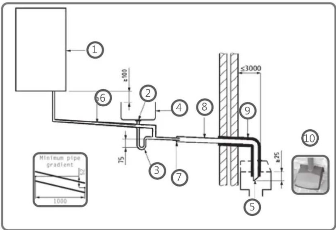
Key
1 Boiler
2 Visible air break at plug hole –
3 75 mm sink, basin, bath or shower waste trap
4 Sink, basin, bath or shower with integral overflow
5 Open end of condensate discharge pipe direct into gully 25 mm min below grating but above water level; end cut at 45°
Note – the maximum external condensate discharge length is 3 metres
6 Minimum internal diameter 19 mm
7 Pipe size transition
8 Minimum internal diameter 30 mm taken to the outside
9 UV resistant, Water/weather proof insulation
10 Fit drain cover/leaf guard

HEATING & HOTWATER INDUSTRY COUNCIL
Manufacturers Instructions shall be referred to when installing boiler condensate discharge pipes
November 2023 Issue 3.0
Internal Condensate Pipe Discharge Termination
When connecting to existing pipework it is critical to review the existing installation to ensure the existing pipework is appropriate for condensate discharge having been run correctly and fully insulated and sealed if this is an external or internal termination.
The possibility of waste pipes freezing downstream of the connection point shall be considered when determining a suitable connection point - e.g. a slightly longer pipe run to an internal soil stack may be preferable to a shorter run discharging directly through the wall to an external drain.
Note - Where "gravity discharge" to an internal termination is not physically possible (e.g. the discharge point is above the appliance location, or access is obstructed by a doorway), or where very long internal pipe runs would be required to reach a suitable discharge point, then a condensate pump shall be used.
External waste pipework shall be:
- Only used to take the condensate waste away and no other waste must be connected to keep the pipework free from restrictions or blockages
• Insulated with waterproof UV resistant material. - All joints sealed correctly stopping water getting between the insulation and waste pipe
- Terminated below the grid but above the water line and a drain/leaf guard fitted.
- Cut at 45 degrees where it terminates into the grid and insulated to the tip of the pipe.
- A minimum thickness of 13mm insulation is recommended for minimum 32mm OD solvent pipe work and fittings
- Where the insulation passes through the wall with a flexible seal for expansion and contraction is required, to stop any moisture getting between the insulation and waste
pipe. This also stops any moisture penetrating through the wall, providing seal supporting energy efficiency

Condensate Pump
Use of a Condensate Pump to an Internal Termination
Condensate can be removed using a proprietary condensate pump, of a specification recommended by the boiler or pump manufacturer. In order to minimise the risk of freezing during prolonged sub-zero spells, the preferred method is internal to the property for terminating the boiler condensate pump to a foul water discharge point should be adopted such as an internal soil stack (preferred method) All waste pipework must be as vertical as possible to take condensate water as fast and as hot as possible to the internal soil stack Any waste pipework being fitted in an unheated area must be enlarged to 32mm OD, insulated and sealed correctly (solvent weld pipe and fitting). UV is not required as fitted internally
Manufacturers Instructions shall be referred to when installing boiler condensate discharge pipes
November 2023 Issue 3.0

HEATING & HOTWATER INDUSTRY COUNCIL
External Connectionst
External Connections
Only fit a correctly insulated external boiler condensate drain connection if an internal gravity or pumped connection is impractical to install.
The pipe work from the boiler shall be of a minimum 19mm ID or if in an unheated area increased to 30mm ID (typically 32mm OD) solvent weld of as per manufacturer's instructions and the condensate discharge pipe shall be run in a standard drainpipe material, e.g. poly (vinyl chloride) (PVC), un-plasticized poly (vinyl chloride) (PVC-U), acrylonitrile butadiene-styrene (ABS), polypropylene (PP) or chlorinated poly (vinyl chloride) (PVC-C).
Note - Fixing centres for brackets should be a maximum of 300mm for flexible pipe and 500mm for solid pipe and manufacturer's recommendations should be followed.
The condensate pipe should be run internally as far as possible before going externally and the pipe diameter shall be increased to a minimum of 30mm ID (typically 32mm OD) if not already, if in an unheated, area before it passes through the wall. The angle of the pipe shall slope downwards by at least 3 degrees as it passes through the wall to assist in maintaining a good velocity as the condensate exits the building.
The external pipe run shall be kept as short as possible to a maximum of 3 metres, taking the most direct and "most vertical" route to the discharge point, with no horizontal sections in which condensate might collect. The external condensate and pipework inside the cavity wall must be insulated to manufacturers instructions

HEATING & HOTWATER INDUSTRY COUNCIL
Manufacturers Instructions shall be referred to when installing boiler condensate discharge pipes
November 2023 Issue 3.0
External Connections
Figure 3 – Connection of condensate discharge pipe to external soil and vent stack
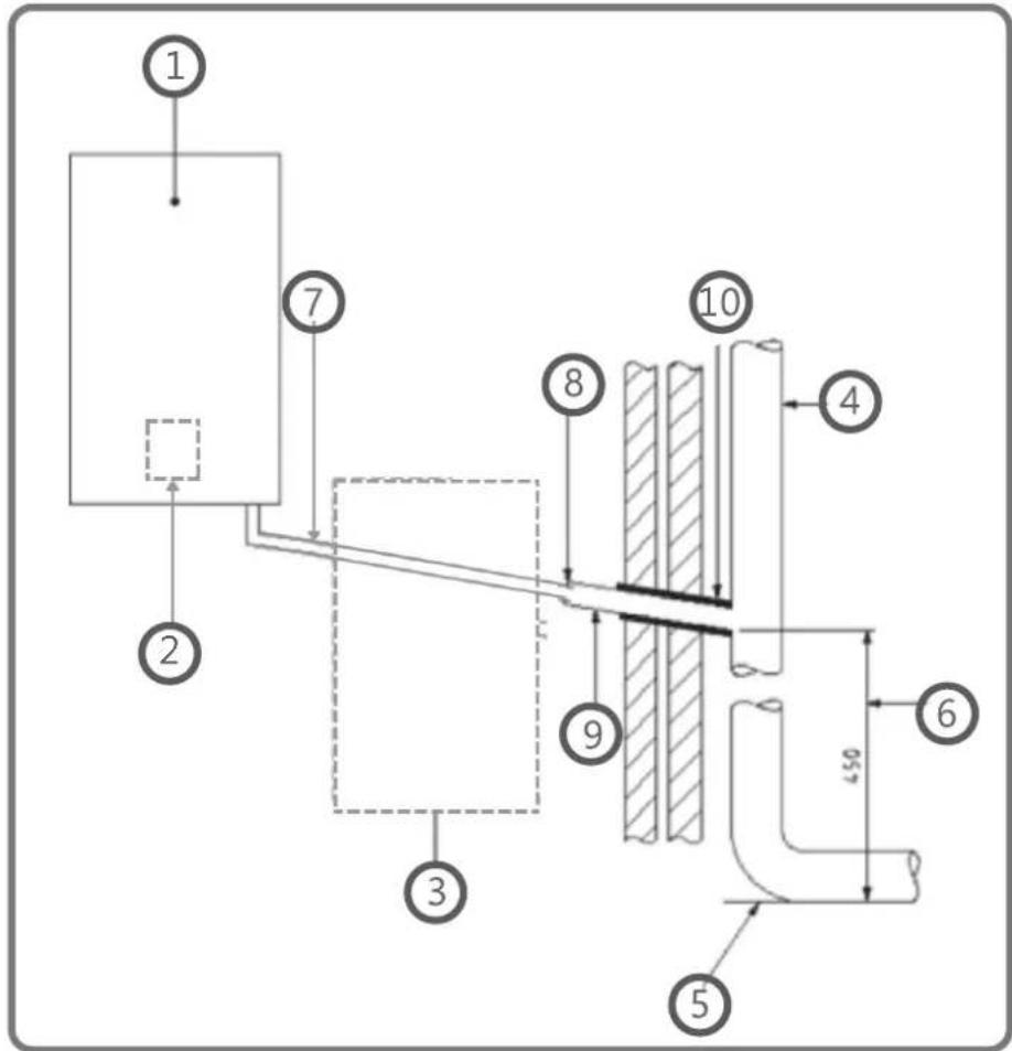
Key
1 Boiler
Internal Trap2
3 Visible air break and trap not required if there is a trap with a minimum condensate seal of 75mm incorporated into the boiler.
4 Soil and vent stack
5 Invert
6 450mm minimum up to three storeys
7 Minimum internal diameter 19 mm
8 Pipe size transition point
9 Minimum internal diameter 30mm taken to the outside
10 UV Resistant, Water/weather proof insulation
Manufacturers Instructions shall be referred to when installing boiler condensate discharge pipes
November 2023 Issue 3.0

HEATING & HOTWATER INDUSTRY COUNCIL
External Connections
Connecting to a rain water downpipe/External Soil Stack
When a rain water downpipe is used as the termination (NB only permissible if this downpipe passes to a combined foul and rainwater drainage system) an external air break shall be installed between the condensate discharge pipe and the downpipe to avoid reverse flow of rainwater into the boiler should the downpipe itself become blocked, flooded or frozen.
Figure 4 shows a suitable connection method. Pipe insulation should be fitted.
External Termination of the Condensate Pipe
Where the condensate discharge pipe is terminated over an open foul drain or gully, the pipe should terminate below the grating level, but above water level, in order to minimise "wind chill" at the open end. Pipe drainage and resistance to freezing will be improved if the termination end of the condensate pipe is cut at 45 degrees as opposed to a

natural_image
Close-up of a textured surface with a diagonal line cutting through it, against a blurred brick wall background (no text or symbols)The use of a drain cover (such as those used to prevent blockage by leaves) shall be fitted to offer further protection from wind chill. Figure 4 (following page) shows a suitable connection method. Where the condensate drain pipe terminates in a purpose-designed soakaway any above-ground section of condensate discharge pipe should be run and insulated as described above. Figure 6 (following page)

HEATING & HOTWATER INDUSTRY COUNCIL
Manufacturers Instructions shall be referred to when installing boiler condensate discharge pipes
November 2023 Issue 3.0
External Connections
Figure 4 – External termination to rainwater downpipe (NB only combined foul/rainwater drain)

Key
1 Condensate discharge pipe from boiler
2 Pipe size transition point
3 Water/weather proof, UV resistant insulation
4 43mm 90° male/female bend
5 External rain water pipe into foul water
6 External air break
7 Air gap
868mm PVC strapon fitting
9 Minimum internal diameter 19mm
10 Minimum external diameter 30mm and through the wall
11 End cut at 45°

natural_image
Two black-and-white photos showing a pipe joint attached to a brick wall, with no visible text or symbols.Manufacturers Instructions shall be referred to when installing boiler condensate discharge pipes
November 2023 Issue 3.0

HEATING & HOTWATER INDUSTRY COUNCIL
External Connections
Figure 5 – Preferred Method: External drain, gully or rainwater hopper
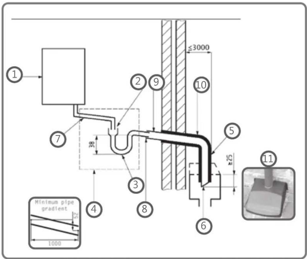
Key
1 Boiler
2 Visible air break
3 38mm minimum trap
4 Visible air break and trap not required if there is a trap with a minimum condensate seal of 38 mm incorporated into the boiler – refer to manufacturer's instructions
5 External length of pipe 3 m maximum
6 Open end of condensate discharge pipe direct into gully 25 mm min below grating but above water level; end cut at 45°
7 Minimum internal diameter 19mm increased to a min of 30mm ID (typically 32mm OD) in an unheated area
8 Pipe size transition point
9 Minimum internal diameter 30mm to the outside
10 Water/weather proof and UV resistant insulation
11 Fit drain cover/leaf guard

HEATING & HOTWATER INDUSTRY COUNCIL
Manufacturers Instructions shall be referred to when installing boiler condensate discharge pipes
November 2023 Issue 3.0
External Connections
Figure 6 – Example of a purpose made soakaway
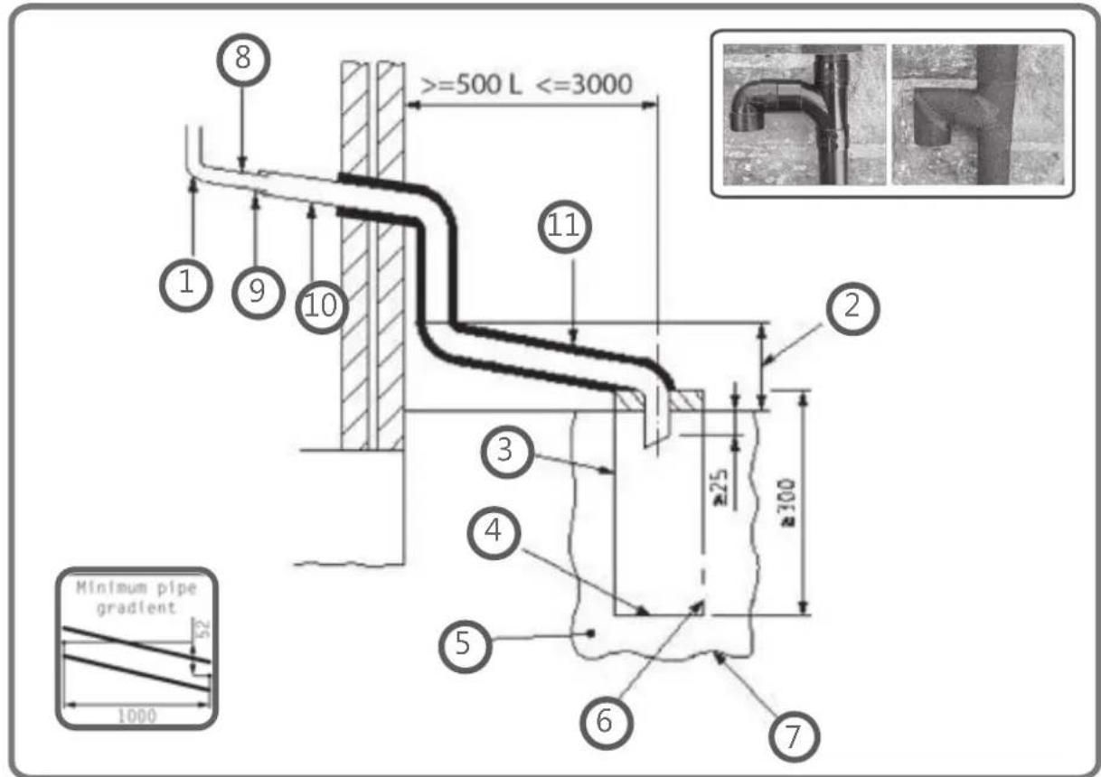
Key
1 Condensate discharge pipe from boiler
2 Ground (this section of the condensate discharge pipe may be run either above or below round level); End cut at 45°
3 Diameter 100 mm minimum plastic tube
4 Bottom of tube sealed
5 Limestone chippings
6 Two rows of three 12 mm holes at 25 mm centres, 50 mm from bottom of tube and facing away from house
7 Hole depth 400 mm minimum by 300 mm diameter
8 Minimum internal diameter 19 mm
9 Pipe size transition point
10 Minimum external diameter 30 mm
11 Water/weather proof and UV resistant insulation
Manufacturers Instructions shall be referred to when installing boiler condensate discharge pipes
November 2023 Issue 3.0

HEATING & HOTWATER INDUSTRY COUNCIL
Other considerations
Unheated Areas in Buildings
Internal condensate drainage pipes run in unheated areas such as lofts, basements and garages shall be treated as external connections and insulated accordingly. Weather proof materials may not be necessary but where separate sections of insulation join together, including elbow joints then these should be connected, insulated and sealed correctly to prevent them coming apart with a suitable material to help prevent freezing.
Insulation Materials
Insulation used for external condensate pipes, shall have an outer coating that is weather proof, and UV resistant. Use a minimum of 13mm thick insulation for 32mm external pipes. Ensure all pipework is insulated and sealed correctly
Use of Air Breaks In Condensate Discharge Pipes
Heating engineers should follow manufacturer's instructions on the use of air breaks in condensate discharge pipes. An air break is normally required for both rainwater and soak away connections. Refer to manufacturer's instructions for further details on for air break requirements.
Soakaway
If a soakaway is the only alternative to discharge the condensate an external insulated and sealed air break is required. This will allow water to be discharged from the condensate pipe should the soakaway become saturated, and will allow the boiler to continue to operate. Note: If water is discharged from this 'overflow', then increasing the volume of the soakaway pit should be considered.

natural_image
Close-up of a black pipe fitting against a textured wall (no text or symbols visible)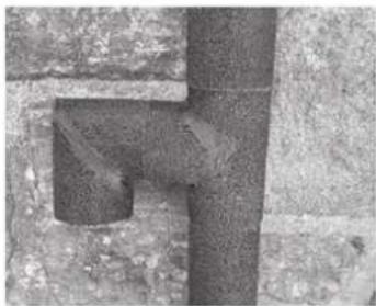
natural_image
Close-up of a rusted metal pipe joint (no text or symbols visible)
HEATING & HOTWATER INDUSTRY COUNCIL
Manufacturers Instructions shall be referred to when installing boiler condensate discharge pipes
November 2023 Issue 3.0
Alternative Solutions
Cold weather protection
Cold weather protection methods approved or endorsed by boiler manufacturers and/or service organisations may be adopted if these are considered suitable by the parties involved. It is the responsibility of the manufacturer of these products to ensure they have completed the necessary testing or calculations to ensure the product offers suitable protection to prevent the condensate pipe from freezing. The product manufacturer should provide information as to what level of external temperature and for what time period the product can protect against sub-zero temperatures, i.e. -15°C for 48 hours.
Electric Trace Heating
Trace heating with an external thermostat can be fitted to the external condensate pipe to raise the temperature of the condensate pipe in freezing conditions. Trace heating takes the form of an electrical heating element run in physical contact along the length of the condensate pipe. The pipe still needs to be insulated and sealed correctly to retain heat losses from the pipe. Heat generated by the element then maintains the temperature of the pipe. If such a system is used then the installation instructions of the trace heating manufacturer and any specific recommendations regarding pipe diameter, insulation, etc. should be followed. All other relevant guidance on condensate discharge pipe installation should also be followed.
Auxiliary Syphon – Fitted Internally
Auxiliary siphons fitted inside the premises assist with the siting of the boiler where an external condensate pipe must be fitted. The storage capacity of the auxiliary siphon increases the volume of condensate discharge reducing the risk of freezing. A further reduction in the potential for the pipe to freeze is achieved when combined with the external insulation requirements and sealing correctly. The aim is to keep the condensate discharge running as fast and as hot as possible, this heats the waste pipe and prevents freezing.
Manufacturers Instructions shall be referred to when installing boiler condensate discharge pipes
November 2023 Issue 3.0

HEATING & HOTWATER INDUSTRY COUNCIL
Annex A
Note – Annex A details remedial actions for householders which can be taken if a condensate discharge pipe freezes. This may result in requests for alteration to condensate discharge pipework, in which case the guidance above should be followed.
Frozen Condensate Information Leaflet – Our customer information guide on frozen boiler condensate discharge is also available for download. It includes a condensate assessment form, for engineers to complete and advice to customers during extreme cold weather conditions. www.hhic.org.uk/resources.
Dear Householder,
Your heating engineer has noted that your boiler condensate discharge pipe may be at risk of freezing in prolonged, and extreme cold weather conditions. In recent years we have seen temperatures as low as -20*c in some parts of the UK.
The concern is that your pipe runs externally or in an unheated space for at least some of its length and is liable to freeze in these extreme temperatures as it is not installed in line with the latest guidance, to help guard against freezing. If your pipe freezes, it will cause your boiler to go into “shut off” at a time when you need your heating and hot water the most.
Your heating engineer will advise you on the solutions available to reduce the risk of your pipe freezing, including running the discharge pipe to an internal drainage point (the preferred method if you have an internal soil stack), or installing one of the available products designed to give you added protection against freezing conditions. They will also clearly identify the external condensate discharge pipe for your future reference and may apply an identification label or tape.

HEATING & HOTWATER INDUSTRY COUNCIL
Manufacturers Instructions shall be referred to when installing boiler condensate discharge pipes
November 2023 Issue 3.0
Annex A
Your Engineer has identified the potential for your boiler to freeze in extreme conditions as the following:
| Risk category Explanation Engineer selection | ||
| RED High risk of | freezing- TAKE ACTION | |
| AMBER Medium | risk of freezing- Strongly advise action to be taken | |
| GREEN Low risk | but some improvement required | |
Work required:
Name:
Company:
Telephone:
Email:
Manufacturers Instructions shall be referred to when installing boiler condensate discharge pipes
November 2023 Issue 3.0

HEATING & HOTWATER INDUSTRY COUNCIL
Annex A
Thawing Frozen Condensate Pipes
Below is an explanation of what you would need to do to resolve the problem in the event that the pipe was to freeze. We would highly recommend getting a professional to assess the situation and resolve the problem by upgrading the condensate. If you do try to unfreeze your condensate, please take care as there are risks due to the related weather conditions.
1. Locate the blockage
The Condensate discharge pipe usually freezes at the most exposed points outside, such as the open end of the pipe, at a bend or elbow, or where there is a dip in the pipe where condensate can collect. (If the condensate has no insulation there may be an extensive frozen area)
2. Thaw the Frozen Pipe
The Condensate can be thawed in a number of ways. By applying a hot water bottle, a microwaveable heat packs around the blockage or by pouring warm water onto the pipe. Do not use boiling water. Do not use water if your condensate discharge pipe is not easily reached from ground level, Do not put yourself at any undue risk. Seek assistance and engage a professional heating engineer. Be aware that if you are pouring water onto the pipe this can also quickly freeze on the ground, causing a slip hazard.
3. Reset/ Restart the boiler
Once the frozen blockage has been cleared, the boiler will usually need to be reset, and advice on how to do this can be found in the user instructions manual for your boiler. Normally this will involve simply pressing a reset button on the front of the boiler, or in some cases by isolating the electrical supply to the boiler and switching it back on

HEATING & HOTWATER INDUSTRY COUNCIL
Manufacturers Instructions shall be referred to when installing boiler condensate discharge pipes
November 2023 Issue 3.0
APPENDIX 2
FLOWCHART FOR CO AND COMBUSTION RATIO CHECK ON COMMISSIONING A CONDENSING BOILER
PRIOR TO CO AND COMBUSTION RATIO CHECK
The installation instructions should have been followed, gas type verified and gas supply pressure/rate checked as required prior to commissioning.
As part of the installation process, ESPECIALLY WHERE A FLUE HAS BEEN FITTED BY PERSONS OTHER THAN THE BOILER INSTALLER, visually check the integrity of the whole flue system to confirm that all components are correctly assembled, fixed and supported. Check that manufacturer's maximum flue lengths have not been exceeded and all guidance has been followed (e.g. Gas Safe Technical Bulletin TBOOB).
The flue gas analyser should be of the correct type, as specified by BS 7967
Prior to its use, the flue gas analyser should have been maintained and calibrated as specified by the manufacturer. The installer must have the relevant competence for use of the analyser.
Check and zero the analyser IN FRESH AIR as per analyser manufacturer's instructions.

flowchart
graph TD
    A["NOTE"] --> B["the air gas ratio valve is factory-set and must not be adjusted DURING COMMISSIONING unless this action is recommended after discussions with SIME LTD."]
    B --> C["If any such adjustment is recommended and further checking of the boiler is required the installer/service engineer must be competent to carry out this work and to use the flue gas analyser accordingly."]
    C --> D["If the boiler requires conversion to operate with a different gas family [e.g. conversion from natural gas to LPG"] separate guidance will be provided by the boiler manufacturer and must be followed.]
    D --> E["Is CO less than or equal to 20.6% and CO2 less than 0.2%"]
    E --> F{Is CO less than 350ppm AND CO/CO2 ratio less than 0.004}
    F -->|YES| G["SET BOILER TO MAXIMUM RATE\nSet the boiler to operate at maximum rate [full load condition"]. Allow sufficient time for combustion to stabilise.]
    F -->|NO| H["CHECK CO AND COMBUSTION RATIO AT MAXIMUM RATE\nWith boiler still set at maximum rate, insert analyser probe into flue gas sampling point. Allow readings to stabilise before recording."]
    H --> I["Is CO less than 350ppm AND CO/CO2 ratio less than 0.004"]
    I --> J{Is CO less than 350ppm AND CO/CO2 ratio less than 0.004}
    J -->|YES| K["SET BOILER TO MINIMUM RATE\nIn accordance with boiler instructions, set boiler to operate at minimum rate (to minimum load condition). Allow sufficient time for combustion to stabilise."]
    J -->|NO| L["Check all seals around the appliance burner, internal flue seals, door and case seals. Rectify where necessary."]
    L --> M["Turn off appliance and call SIME LTD Technical Helpline for advice.\nthe appliance must not be commissioned or used, until problems are identified and resolved."]
    M --> N{Is CO less than 350ppm AND CO/CO2 ratio less than 0.004}
    N -->|YES| O["SET BOILER TO MINIMUM RATE\nIn accordance with boiler instructions, set boiler to operate at minimum rate (to minimum load condition). Allow sufficient time for combustion to stabilizeise."]
    N -->|NO| P["Check and record CO and combustion ratio at both maximum AND minimum rate before contacting SIME LTD."]
    P --> Q["Turn off appliance and call SIME LTD Technical Helpline for advice.\nthe appliance must not be commissioned or used until problems are identified and resolved."]
    Q --> R["VOILER IS OPERATING SATISFACTORILY\nno further actions required\nEnsure test points are capped, boiler case is correctly replaced and all other commissioning procedures are completed.\nComplete Benchmark Checklist, recording CO and combustion ratio readings as required."]
    R --> S["VEIIFY FLUE INTEGRITY\nAnalyser readings indicate that combustion products and inlet air must be mixing. Further investigation of the flue is therefore required.\nCheck that flue components are assembled, fixed and supported as per boiler/flue manufacturer's instructions.\nCheck that flue and flue terminal are not obstructed."]
    S --> T["Is CO less than or equal to 20.6% and CO2 less than 0.2%"]
    T --> U{Is CO less than or equal to 20.6% and CO2 less than 0.2%}
    U -->|NO| V["Turn off appliance and call SIME LTD Technical Helpline for advice.\nthe appliance must not be commissioned or used, until problems are identified and resolved."]
    V --> W{Is CO less than or equal to 20.6% and CO2 less than 0.2%}
    W -->|YES| X["CHECK CO AND COMBUSTION RATIO AT MAXIMUM RATE\nWith boiler still set at maximum rate, insert analyser probe into flue gas sampling point. Allow readings to stabilizeise before recording."]
    W -->|NO| Y["Check all seals around the appliance burner, internal flue seals, door and case seals. Rectify where necessary."]
    Y --> Z{Is CO less than 350ppm AND CO/CO2 ratio less than 0.004}
    Z -->|YES| AA["SET BOILER TO MINIMUM RATE\nIn accordance with boiler instructions, set boiler to operate at minimum rate (to minimum load condition). Allow sufficient time for combustion to stabilizeise."]
    Z -->|NO| AB["CHECK CO AND COMBUSTION RATIO AT MINIMUM RATE\nWith boiler set at minimum rate, insert analyser probe into flue gas sampling point. Allow readings to stabilizeise before recording."]
    AB --> AC["NOTE: If manufacturer's instructions do not specify how to set boiler to minimum rate contact Technical Helpline for advice."]
    AC --> AD["Is CO less than 350ppm AND CO/CO2 ratio less than 0.004"]
    AD --> AE["BOILER IS OPERATING SATISFACTORILY\nno further actions required\nEnsure test points are capped, boiler case is correctly replaced and all other commissioning procedures are completed.\nComplete Benchmark Checklist, recording CO and combustion ratio readings as required."]
sime
Sime Ltd
Unit 6 Flockton Park
Holbrook Avenue
Holbrook Industrial Estate, Sheffield, S20 3FF
Phone: 0345 901 1114
www.sime.co.uk
Email: enquiries@sime.co.uk
- IMPORTANT NOTICE
- SAFE HANDLING
- WARNING
- NOTICE
- Code Of Practice
- Standards of Work
- Customer Service
- The Benchmark Scheme
- Important Information
- WARNINGS
- PROHIBITION
- LIST OF ABBREVIATIONS USED IN THE MANUAL
- MANUAL STRUCTURE
- COMPLIANCE
- SYMBOLS
- ELECTRICAL HAZARD
- CAUTION
- USERINSTRUCTIONS
- TABLE OF CONTENTS
- USING THE BOILER MURELLE REVOLUTION 12
- MAINTENANCE 18
- DISPOSAL 18
- VERY IMPORTANT!
- USING THE BOILER MURELLE REVOLUTION
- Main control panel (remote control)
- Using the buttons
- BUTTON (A)
- MULTIFUNCTION ENCODER
- BUTTON (B)
- Start-up
- Preliminary checks
- Ignition
- Settings using the MODE button
- TimeProgramming
- Holidayfunction
- Fault warnings
- Quick settings
- IMPORTANT INFORMATION FOR THE SET AMBIENT TEMPERATURE
- Navigating using the MODE button
- Servicing
- External cleaning
- Cleaning the case
- Disposal of the equipment (European Directive 2012/19/EU)
- DESCRIPTION OF THE APPLIANCE
- DESCRIPTION OF THE APPLIANCE 20
- DESCRIPTION OF THE APPLIANCE
- Characteristics
- Operation summary
- Heating
- Domestic Hot Water (DHW)
- Check and safety devices
- Symbols on the appliance
- Symbols on the packaging box
- Identification
- Technical data plates
- Structure
- Technical features
- Boiler (gas side)
- Lower Heat Output (Hi):
- Gas category G20Y20:
- Main water circuit
- KEY:
- Sensors
- Correspondence of Temperature Detected/Resistance
- Expansionvessel
- Circulation pump
- Boiler control panel (gas side)
- FUNCTIONAL BUTTONS
- DISPLAY
- Heat Pump control panel
- Main control panel (remote control)
- Using the buttons
- Wiring diagrams
- Boiler
- Heat pump
- Interconnecting the appliance, outdoor air temperature probe and main control panel (remote control)
- Installer must:
- INSTALLATION AND SERVICING INSTRUCTIONS
- Installer Checklist
- Has the pump been rotated manually?
- Has the D.H.W. flow rate been set to the customer requirements?
- INSTALLATION 38
- COMMISSIONING 55
- MAINTENANCE 72
- MURELLE REVOLUTION CHECKLIST 30 77
- sime 5 INSTALLATION
- Receiving the product
- Dimensions and weight
- Handling
- Ventilation requirements
- New installation or installation of a replacement appliance
- Cleaning the system
- Characteristics of feedwater and system treatment
- Boiler installation
- Then:
- Plumbing connections
- Plumbing accessories (optional)
- Condensate outlet/collection
- Thermal insulation of the pipes
- Gas supply
- Connecting the flue
- Flue Terminal Positions
- Smoke outlet and air inlet (combustion/heat pump)
- Smoke outlet (∅ 80 mm)
- Coaxial ducts ( 160/200 mm) for air inlet/outlet (combustion/heat pump)
- Holes for air inlet/outlet
- Fitting the air ducts
- Mounting the main control panel (remote control)
- Electrical connections and External controls
- External temperature sensor
- Procedure for selecting the climatic curve:
- Chrono-thermostat or room thermostat for the zone
- EXAMPLE of use of the command/control device on some types of heating systems
- Refilling or emptying
- Method of filling a sealed system
- SYSTEMFilling
- Remove the front panel:
- Domestic hot water circuit:
- Heating circuit:
- EMPTYING operations
- Preliminary operations
- Before commissioning
- Automaticself-calibratingprocedure
- Main control panel display and settings
- Settings using the MODE button
- Fault warnings
- Quick settings
- Settings using the MENU button
- GENERAL SETTINGS menu
- INFORMATION menu
- TECHNICAL menu
- sime
- TECHNICAL ASSISTANCE CENTRE menu
- Parametersettinganddisplay
- Fault / malfunction codes
- Boiler fault (gas side)
- Type No. Description
- Heat pump fault
- Display of operating data and counters
- Checks
- Chimney sweep function
- Domestic hot water comfort function (preheating)
- Gasconversion
- Servicing
- External cleaning
- Cleaning the case
- Burner Inspection
- Burner access
- Cleaning the burner and the combustion chamber
- Checking the ignition/detection electrode
- Cleaning the smoke exchanger
- Final operations
- Cleaning the heat pump
- Checks
- Checking the flue
- Checking the expansion vessel pressure
- Circuit Board Replacement
- MURELLE REVOLUTION CHECKLIST 30
- ANNEXES
- PRODUCT DATA SHEETMURELLE REVOLUTION 30
- Benchmark Commissioning & Warranty Validation Service Record
- SERVICE & INTERIM BOILER WORK RECORD
- Service provider
- EXPLODED VIEWS
- APPENDIX 1 (GUIDANCE HHIC)
- Manufacturer's Instructions
- Internal Condensate Pipe Discharge Termination
- Key
- Internal Condensate Pipe Connection with External Termination
- Condensate Pump
- Use of a Condensate Pump to an Internal Termination
- External Connectionst
- External Connections
- Connecting to a rain water downpipe/External Soil Stack
- External Termination of the Condensate Pipe
- Other considerations
- Unheated Areas in Buildings
- Insulation Materials
- Use of Air Breaks In Condensate Discharge Pipes
- Soakaway
- Alternative Solutions
- Cold weather protection
- Electric Trace Heating
- Auxiliary Syphon – Fitted Internally
- Annex A
- Thawing Frozen Condensate Pipes
- Locate the blockage
- Thaw the Frozen Pipe
- Reset/ Restart the boiler
- APPENDIX 2
- PRIOR TO CO AND COMBUSTION RATIO CHECK
- Sime Ltd
Brand : SIME
Model : MURELLE REVOLUTION 30
Category : Boiler