RGP-12SR - Contrôleur électrique industriel ENTES - Free user manual and instructions
Find the device manual for free RGP-12SR ENTES in PDF.


| Product Type | Voltage Monitoring Relay |
| Dimensions (W x H x D) | 90 x 72 x 58 mm |
| Weight | 150 g |
| Power Supply | 3-Phase, 400V AC, 50/60 Hz |
| Rated Voltage | 400V AC |
| Rated Current | 5A |
| Adjustable Voltage Threshold | Yes, via potentiometer (300-500V) |
| Output Contacts | 1 SPDT relay, 8A / 250V AC |
| Display | LED indicators for status |
| Mounting | DIN rail (DIN 43880) |
| Operating Temperature | -10°C to +55°C |
| Protection Rating | IP20 |
| Compliance | CE, RoHS |
| Main Functions | Overvoltage, undervoltage, phase sequence, phase loss monitoring |
| Maintenance | Periodic cleaning with dry cloth; check connections annually |
| Safety | Use appropriate circuit breaker; follow local electrical regulations |
| Spare Parts Availability | Not available separately; replace entire unit |
| General Information | Designed for 3-phase systems; automatic reset on fault recovery |
| Connection Type | Screw terminals (up to 2.5 mm²) |
| Product Series | RGP |
Frequently Asked Questions - RGP-12SR ENTES
User questions about RGP-12SR ENTES
0 question about this device. Answer the ones you know or ask your own.
Ask a new question about this device
Download the instructions for your Contrôleur électrique industriel in PDF format for free! Find your manual RGP-12SR - ENTES and take your electronic device back in hand. On this page are published all the documents necessary for the use of your device. RGP-12SR by ENTES.
USER MANUAL RGP-12SR ENTES
3 Phase Power Factor Controllers
Index
1. Introduction...... 8
1.1 General Specifications 8
1.2 RGP Product Family 8
1.3 Operating Conditions.... 8
1.4 Led Introduction.... 9
1.5 Display Smiley View 9
1.6 Front Panel View 10
1.7 Key Functions.... 11
1.7.1 Generator, Temperature, Alarm and Fan Indicators 11
1.7.2 Power factor correction Shortcut Menu 11
1.7.2 Energy Shortcut Menu.... 12
1.7.3 Total Power Shortcut Menu 12
1.7.4 V L-N Shortcut Menu 12
1.7.5 Tutorial Mode.... 13
1.8 Technical Specifications 13
1.9 Connection Diagram 14
1.10 Start-up the RGP Product 15
2. Using the Product.... 16
2.1 Setup 16
3. Menus 16
3.1 Settings Menu 16
3.1.1 User Settings Menu 17
3.1.1.1 User Language Setting 17
3.1.1.2 Back Light Setting 17
3.1.1.3 User Smiley Mode Setting 17
3.1.1.4 User Security Settings 17
3.1.1.5 User Password Settings.... 17
3.1.2 Setup Settings Menu 17
3.1.2.1 Connection Correction 18
3.1.2.2 Current Transformer 18
3.1.2.3 System Frequency Settings 19
3.1.2.4 Auto Setup Setting 19
3.1.2.5 Auto Setup SVC Setting 20
3.1.2.6 Step Setting 20
3.1.2.7 Driver Setting (on SR models only) 21
3.1.3 Power factor correction Settings....21
3.1.3.1 Power factor correction Program 21
3.1.3.2 Power factor correction Mode 22
3.1.3.3 Target CosΦ 22
3.1.3.4 Generator Target CosΦ 22
3.1.3.5 Three-phase On Delay 24
3.1.3.6 Three-phase Off Delay 24
3.1.3.7 Single phase Delay 24
3.1.3.8 Discharge Time 24
3.1.3.9 Power factor correction Manual Step 25
3.1.3.10 Power factor correction Manual SVC Step 25
3.1.3.11 Power factor correction Reading Day 25
3.1.4 Communication Settings Menu....25
3.1.4.1 Modbus Setting 26
3.1.5 Alarms Menu....27
3.1.5.1 Alarm Delay Time.... 27
3.1.5.2 Inductive Rate Alarm 28
3.1.5.3 Inductive Rate Warning 28
3.1.5.4 Capacitive Rate Alarm 28
3.1.5.5 Capacitive Rate Warning 28
3.1.5.6 Value Loss Alarm 29
3.1.5.7 Value LossWarning 29
3.1.5.8 Contactor Service Life Warning This warning.... 29
3.1.5.9 Contactor Service Life Alarm 30
3.1.5.10 Voltage Alarm 30
3.1.5.11 THDV Alarm 31
3.1.5.12 THDI Alarm 31
3.1.5.13 Temperature alarm.... 32
3.1.5.14 Special Alarm 32
3.1.6 Time Menu....33
3.1.6.1 Time Range 33
3.1.6.2 Date 33
3.1.6.3 Time 33
3.1.7 System Menu 34
3.1.7.1 Software Version 34
3.1.7.2 Hardware Version 34
3.1.7.3 Serial Number 34
3.1.8 Reset Menu 35
3.1.8.1 Restore Factory Settings 35
3.1.8.2 Energy Counter Reset 35
3.3 Power factor correction Menu 36
3.3.1 Power factor correction Today 36
3.3.2 Power factor correction Yesterday ....36
3.3.2 Power factor correction Last 7 Days ...... 37
3.3.4 Power factor correction This Month .... 37
3.3.5 Power factor correction Last Month.... 37
3.4 Power 38
3.4.1 Power Cos Φ 38
3.4.2 Power Factor 38
3.4.3 Total Power 38
3.4.4 Active Power 39
3.4.5 Reactive Power 39
3.4.6 Apparent Power 39
3.5.1. Active Import Energy (AI)....40
3.5.2. Active export energy (AE) 40
3.5.3. Inductive reactive energy (Enr r) 40
3.5.4. Capacitive reactive energy (Enr r) 41
3.5.5. Apparent energy (S) 41
3.5.6. Generator Energy (Gen)......41
3.6 Measurements 42
3.6.1 Voltage (Phase-Neutral) 42
3.6.2 Voltage (Phase-Phase) 42
3.6.3 Current (Phase-Neutral) 42
3.6.4 Frequency 43
3.6.4 Temperature 43
3.7 Harmonics 43
3.7.1 Current Harmonics 43
3.7.2 Voltage Harmonics 44
3.6.3 Current Total Harmonic Distortion (THDI)....44
3.6.4 Voltage Total Harmonic Distortion (THDV) 44
3.8 Messages 45
4 Maintenance.... 52
5 Warranty Terms 52
6 Conformity Data.... 52
7 Annexes.... 53
7.1 Mechanical and Environmental Conditions 53
7.2 Measuring.... 53
7.2.1 Voltage 53
7.2.2 Phase Current 54
7.2.3Power 54
7.2.5Min&Max Values 55
7.2.4Energy 55
7.3 Step 56
7.4 Time.... 56
The RGP Series is the next-generation three-phase reactive power control controllers by ENTES. With its 9 and 12 steps, it controls the three phases separately and strictly the Cos value of each phase to user defined value to prevent companies from being subjected to penalty. The product has separate three phase current and voltage, as well as an RS-485 communication, SVC, Alarm and fan port.
The product has step out up to 9,9+SVC, 12, 12+SVC and 1 alarm output. Connection diagram is at the back of the product.

Copyrights of this manual are reserved and it is strictly prohibited to use any part or content of it.
Read this manual before commissioning and operating the RGP Series products by ENTES. The information given below is important to avoid problems that may emerge during installation and use. Failure to follow the instructions below may result in serious injuries or even death. In this case, the manufacturer cannot be held responsible in any manner.
Please contact the manufacturer for all technical notices: teknikdestek@entes.com.tr
Safety Warnings
- Installation, commissioning, maintenance and operation of the product must be carried out by authorized specialists. The manufacturer is not responsible for damages emerging from failure to follow the instructions.
- Do not install the product if it has been damaged during transportation. Contact your Sales Representative.
- Before installing the product to the switchboard, fit the included battery into the battery compartment.
- Disconnect all power sources before installing the device to the switchboard.
- Your product is suitable for terminal connection only.
- First of all, connect the voltage and current measurement inputs.
- It is mandatory to connect a three-phase capacitor to the reference step.
• Before operating your product, make sure that all terminal connections are correct.
- Do not remove the front panel or any of the connections while the product is connected to the mains.
- When the battery is dead, de-energize the product to replace the battery.
- Do not dismantle the product; there are no user-serviceable parts. If you dismantle the product, the warranty will become void.
- The product is connected to the mains via current transformers. Do not decommission the product if you are not sure if the terminals have been short circuited or connected to another parallel load with a sufficiently low impedance. Otherwise, dangerously high voltages might be observed on the secondary terminals of the current transformer.
- Do not use this product for any other purpose other than its intended use.
- The fuse must be F type. Please see the product label for fuse value.
- When installing the product, make sure that its ventilation holes are not blocked so that it can operate with the stated values.
- Connect a button or a circuit breaker between supply inputs of the product and the mains.
- This button or circuit breaker must be close to the product.
- Place a mark to indicate that this button or circuit breaker will be used to separate the product from the mains.

Double insulated - The user will not be subject to electric shock even if they touch low voltage areas when the product is energized. (Display, Buttons, Communication, Battery) Ground Connection is not required.
CAT III
Category 3 - Electronic circuit that can be used in measurement and testing systems. It can be used in industrial measurements.

Caution - Observe the safety rules.

Battery replacement compartment

Alarm output

Fan Output
CUR [L3 | ....| K1] Mains current inputs
[A1 | A2]
Auxiliary supply (apply voltage on this port to operate the product)
SVC SVC driver output
[ VN | ....| V1 ] Voltage output
N.C. No connection
THRM SW Thermic element input
[C1 | C2 | ... | C12] Relay steps
COM1,2
Relay steps common terminal outlet (Insulated on COM1, COM2)
GEN. INPUT [IN1 | IN2] Generator input
[GND | A | B | TR] Connection terminals
RS-485 Connection terminals
1. Introduction
1.1 General Specifications
RGP-9/ 9+SVC/ 12/ 12+SVC reactive power factor controller is intended to perform automatic power power factor correction on three-phase systems. RGP-9/ 9+SVC/ 12/ 12+SVC receives current and voltage information of each phase to ensure individual power factor correction of phases.
This way, it ensures that the correct power factor correction value is reached even in unstable systems.
The product is equipped with CR2032 replaceable battery. If you operate the product without a battery, some data such as the time might, log events and ratios be deleted in case of power failure. The product is equipped with Wide Screen, Segment LCD and 4 buttons. Functions of the buttons are shown in Table 4.
** The device with SVC driver has up to 12 steps and an additional SVAR driver.
1.2 RGP Product Family
Product codes and specifications are given in the table.
| RG Product Family | Display 9 Steps | 12 Steps | 9 + SVC | 12 + SVC | SVC | RS-485 (OPS) | |
| RGP-9 Segment LCD | ● | ||||||
| RGP-9S Segment LCD | ●● | ||||||
| RGP-12 Segment LCD | ● | ||||||
| RGP-12S Segment LCD | ●● | ||||||
| RGP-12SR Segment | LCD ●● | ● |
Table 1: RGP Product Family
1.3 Operating Conditions
Ensure that the operating conditions given in the table below are provided to obtain the desired efficiency from your product.
| Operating Conditions | Value Range |
| Operating Voltage | 100-270 (-15%+10%) VAC/ VDC 85-300 VAC |
| Operating Frequency | 50-60 Hz |
| Power Consumption | <25VA, <20W |
| Maximum Measurable Current | 6A AC |
| Maximum Measurable Voltage | 400 VAC(LN) |
| Maximum Number of Steps | 12 |
| Communication speed | 2400 / 256000 bps |
| Storage Temperature | -30 / +80°C |
| Operating Temperature | -20 / +70°C |
| Maximum Humidity | 95% (noncondensing) |
| Battery | 3V CR2032 |
Table 2: Operating Conditions
1.4 LED Indicator
| LED Color LED Status Description | ||
| Red | Stable | Alarm Available |
| Green | Flasher | Communication Available |
| Stable | No Problems | |
| Blue | Stable | Generator Enabled |
| Yellow | Stable | Warning Available |
Table 3: Notification LED
1.5 Display Smiley View
The messages that your device can give and the table of the Alarm / Warning status are as follow. Below you can see in which situations “Smiley Job” is switched and whether this situation can be turned off.
| Message Level LED Job Pop- | Up Smiley Job Can it be turned off? | ||||
| No L1, L2, L3 | ALARM | Yes Yes Yes No, it is system | alarm. | ||
| Inductive rate exceeded in the last 7 days | ALARM | Yes Yes Yes No, but the ratio can be changed. | |||
| Inductive rate warning for the last 7 days | ALARM | Yes Yes Yes No, but the ratio can be changed. | |||
| Inductive rate warning for the last 7 days | WARNING | Yes Yes Yes No, but the ratio can be changed. | |||
| Capacitive rate warning for the last 7 days | WARNING | Yes Yes Yes No, but the ratio can be changed. | |||
| Step capacity alarm | ALARM | Yes Yes No | It cannot be turned off, but the value can be changed. | ||
| Step capacity warning | WARNING | Yes Yes No | It cannot be turned off, but the value can be changed. | ||
| Switching number alarm | ALARM | Yes Yes No | It cannot be turned off, but the value can be changed. | ||
| Switching number warning | WARNING | Yes Yes No | It cannot be turned off, but the value can be changed. | ||
| User alarms | ALARM | Yes Yes Yes | It can be turned off, depends on the user. | ||
| SVC thermal | WARNING | Yes Yes | If only compensation program container + reactor+ SVC , Yes | It cannot be closed. | |
| Insufficient capacitor power | WARNING | Yes Yes No It cannot be closed. | |||
| Insufficient reactor power | WARNING | Yes Yes No | It cannot be closed. | ||
| Insufficient single-phase step power | WARNING | Yes Yes No | It cannot be closed. | ||
| In-panel temperature | ALARM | Yes Yes | Yes, only if the step protection feature is on | Default off, can be turned on. Step protection can be turned on, off by default. | |
| High voltage | ALARM | Yes Yes | Yes, only if the step protection feature is on | Default off, can be turned on. Step protection can be turned on, off by default. | |
| High THDV | ALARM | Yes Yes | Yes, only if the step protection feature is on | Default off, can be turned on. Step protection can be turned on, off by default. | |
| High THDI | ALARM | Yes Yes | Yes, only if the step protection feature is on | Default off, can be turned on. Step protection can be turned on, off by default. | |
Smiley action is as follows:
There are different menus for the rear light setting and Smiley mode.
You can proceed to Settings - User Settings - USER SMILEY menu to change the Smiley mode settings. You can proceed to Settings - User Settings - USER LIGHT menu to change the back light settings of the product.
If the product is in Smiley mode and if there is an alarm or warning screen (back screen light on or off), press any key to display the alarm or warning messages for your product. There will be description of the warning or alarm in the navigation section of your product, alarm or warning indication on the screen, and the number of warnings or alarms on the lower bar. You can use the direction key to read the alarms or warnings, or you can press OK to silence the alarm.
1.6 Front Panel View

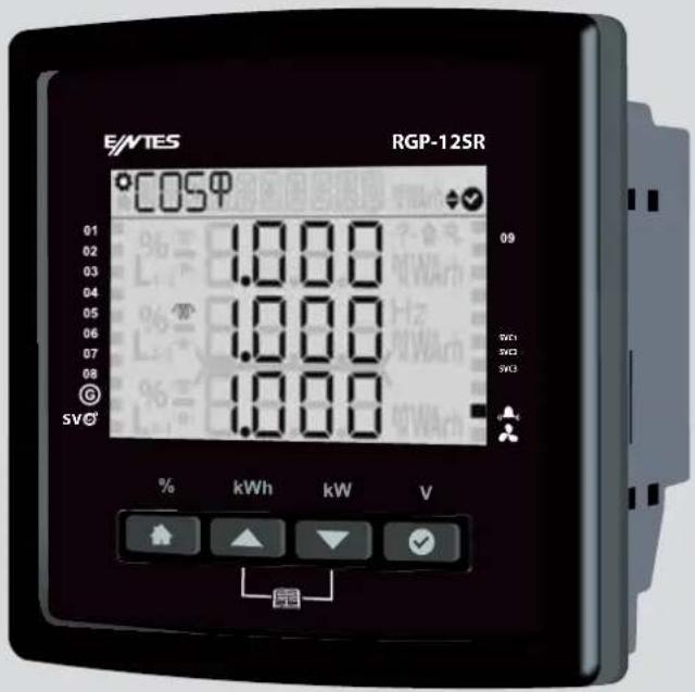
The front panel of the product has Wide Screen Segment LCD, 4 buttons and a notification LED.
Navigation bar contains the name of the current screen menu, alarm description (if there is any active alarm on the system) and the warning description (if there is any active warning on the system).
Step Status Bar is located as a strip to the right and left of the segment LCD.
1.7 Key Functions
| Button |  |  |  |  |
| Description Home Up Down OK | ||||
| Shortcut | Power factor correction (%) | Energy (kWh) | Power (kW) Voltage (V) |
Figure 1: Key Functions
Your ENTES RGP product consists of 8 main menus. You can use the Up and Down keys to navigate the menu or access the desired settings menu.
1.7.1 Generator, Temperature, Alarm and Fan Indicators
Generator ( G ): If the the Generator symbol on the product is active, this means that the Generator is enabled. (If the generator setting is enabled)
Temperature (SV©): If Temperature symbol on the product is active, this means that the SVC thermal element has heated up.
Alarm (▲): If the Alarm symbol on the product is active. The alarm relay is enabled
Fan (✗): If the Fan symbol on the product is active, this means that the Fan Relay has been enabled. It will be reset when the warning condition has been eliminated.
Alarm icons: These icons become active while the critical alarms are available.
-?: Any phase voltage is not connected (Capacitors are switched OFF)
: The rate ratio of 7 day's exceed alarm limit.
☀ : Temperature, Voltage, THDI, THDV exceed it's alarm limit (If the step protection is enabled)
1.7.2 Power factor correction Shortcut Menu
Press and hold the Home button for 2 seconds to access the Power factor correction value for the current month.
In the PFC menu, the first row indicates the Total Inductive Rate, and the third row indicates the Total Capacitive Rate. In the power factor correction details menu, you can display the power factor correction values for today, yesterday, last 7 days, this month and last month.
1.7.2 Energy Shortcut Menu
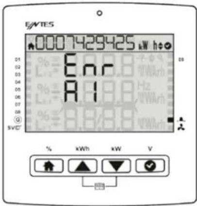
Press and hold the Up button for 2 seconds to display the active import energy menu screen. You can use the Up and Down keys to access the instant parameters for Enr-AI (Active Import Energy), ENR-AE (Active Export Energy), Enr-r (inductive), Enr-r (capacitive), Enr-s (Apparent Energy), Enr-JEn (Generator Energy) of your system.
1.7.3 Total Power Shortcut Menu
Press and hold the Down button for 2 seconds to display the total power menu.

1.7.4 V L-N Shortcut Menu
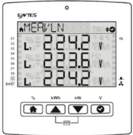
Press and hold OK for 2 seconds to display the VL-N menu. You can see the instant voltage values of your system under this menu.
1.7.5 Tutorial Mode
The Tutorial Mode informs you about the meanings of the functions of the Smiley mode. During first set-up of your product, it is displayed on the screen right after language selection. If you want to see the Tutorial Mode while the product is operating, press and hold the Up and Down keys simultaneously for 2 seconds to enable the Tutorial Mode and display descriptions of the key functions. Once the Tutorial Mode is finished, your product will automatically return to the cosΦ screen.

1.8 Technical Specifications
| Connection Range Terminal Type | ||
| Auxiliary Supply 85-300 | VAC / 50-60 Hz 15VA | 3 x 5.08 mm socket |
| 2.5 mm2 / 4 mm2 TD | ||
| With Fixing Screws | ||
| Voltage Measurement | 3 x 10 – 690 VAC 45-65Hz | 5 x 7.62 mm socket |
| 2.5 mm2 , 4 mm2 TD | ||
| Current Measurement | 3 x 0.005 – 6 A / AC 45-65Hz | 2 x 6 x5.08 mm socket |
| 2.5 mm2 / 4 mm2 TD | ||
| With Fixing Screws | ||
| Relay Output 12 x 250 | VAC 3A 750 VA | 2 x 9 x 5.08 mm socket |
| 2.5 mm2 / 4 mm2 TD | ||
| Generator Input 85 - 300 V AC/DC | 3x5.08 mm socket | |
| 2.5 mm2 / 4 mm2 TD | ||
| Alarm Relay Output / Fan Relay Output | 1 x 250 VAC / 5 A AC 1250 VA | 4x5.08 mm socket |
| 2.5 mm2 / 4 mm2 TD | ||
| RS 485 Port Max. ±12V | 4 x 3.84 mm socket | |
| 1.5 mm2 / 2.5 mm2 TD | ||
| Battery 3 V CR2032 | CR2032 Battery Holder | |
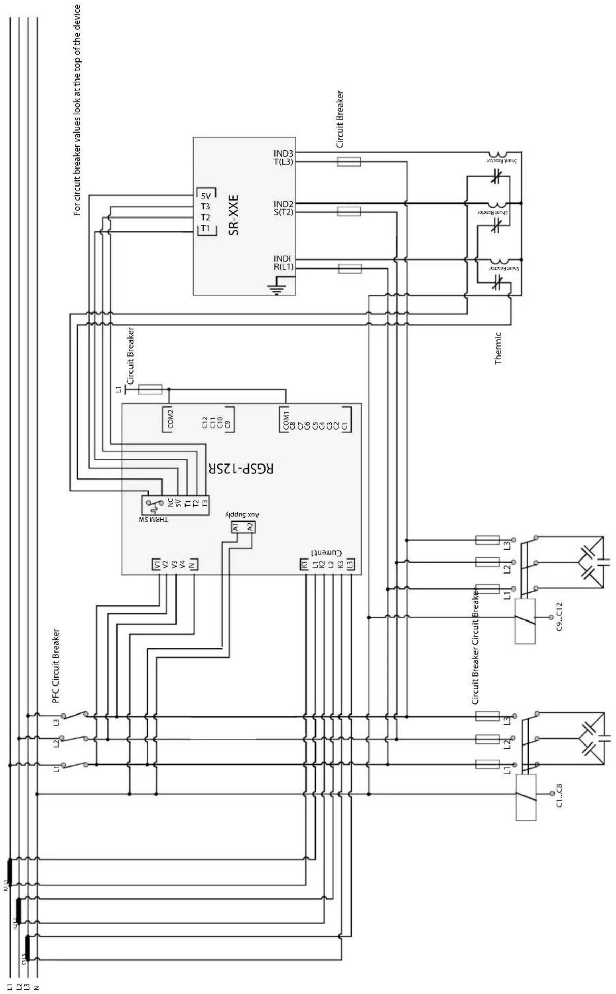
Follow the steps below respectively to make electrical connections of your product.
- For the product to operate properly, insert the three phase, one neutral cable and current cables of the three phases into the relevant inputs on the product.
- Make the step connections as described in the connection diagram. Make sure that you connect a three-phase capacitor to the reference step here.
- You can connect shunt reactors to any step except for the reference step.
- Make the communication connections.
- Establish the alarm outlet connections.
- Insert the battery included in the package.
- Check the connections above and make sure that they are correct. Never energize the product before checking.
- Connect power supply to Aux input.
1.10 Start-up the RGP Product
Follow the steps below respectively to start-up the product.
- Once your product is energized, you will see the Language Selection, Tutorial Mode and Auto Setup menus respectively and you will be prompted to set the relevant parameters.
- The product will run the automatic connection scanning function. Phase currents must have a value other than zero for the product automatically detect the connection error. The product will switch on and off the reference step when correcting the connection error (phase sequence error and current transformers polarity error).
- If the rapidly changes in loads and the non-linear (Thyristor Triac Controlled, with Frequency Converter, UPS etc.) loads are too much, the product might not be able to automatically correct the connection. In this case, switching off this type of loads temporarily, and then de-energize and energize the product and repeat the process.
- Once the connection has been corrected, the product will run the automatic step detection function. It switch on and off the steps one by one to detect their power and connection types.
- You can connect desired number of capacitor and/or reactors to the steps of the RGP product (except for the reference step), as long as they are three-phase, and mono phase
- Once the Step recognition is complete, the product will run the automatic (SVC) recognition function.
- Your product will operate with factory settings during the first use.

Supply voltage is connected separately, Aux Supply, Voltage and Current Measurement inputs are connected to ensure three-phase-neutral. The product will not operate without a three-phase connection.
2. Using the Product
2.1 Setup
When you switch on the product for the first time, you will see the language selection menu and the Tutorial Mode will be active. After the Tutorial Mode screens, you will proceed to the configuration screens for Region Selection, Time Setting, Date Setting, CT Primary, CT Secondary, Target CosΦ, Reference Step settings respectively, you will enter them in accordance with the required information and proceed to the Auto Setup screen. If a power failure occurs before the settings are saved, these setting screens will be displayed again in the next startup.
3.Menus
Your product consists of 8 main menus. These Main Menus are:
• Power Factor Correction
- Power
- Energy
- Measurements
- Harmonics
- Messages
- Settings
- Cos
3.1 Settings Menu
You can press HOME and use the up and down keys to access the Settings menu. If you wish to do something under the Settings menu or change the settings, press OK to go to menu details and change Product or User settings under the Settings menu. Under the Settings menu, the Home (▲) symbol on the upper left corner of the LCD will go off and the Settings symbol (💡) will light. In the Settings menu, you can use thee Up and Down keys to navigate submenus and press OK to see or change menu details. If you have made a change in the menus, you will be asked if you would like to save the change when you are leaving the Settings menu. If you say Yes, the settings will be saved on the product. If you say No, the changes will not be saved and you will leave the menu.
Settings that can be changed in the Settings menu:
- User
- Setup
• Power factor correction - Communication
- Alarm
- Time
- System
- Reset
3.1.1 User Settings Menu
In the User Settings submenu, you can set language, light, Smiley mode, security and password. To exit the submenus, press HOME. You will be asked if you want to save the changes or not. Use the Up and Down keys to select Yes or No, and press OK to save the setting.
3.1.1.1 User Language Setting It is the submenu where you can set the language for your product. You can proceed to Settings- User Settings- USER LANGUAGE submenu for the changes you want to make in the language of the product.
3.1.1.2 Back Light Setting It is the submenu where you can adjust the back Light for your product. You can proceed to Settings- User Settings- USER LIGHT submenu for the changes you want to make in the light of the product. When you enter the menu, the product will give you Yes, No and Auto options. Select Yes if you want the light to be permanently on at the background, select No if you want no light on the background, select Auto if you want the light to be on for some time (half an hour) and then go off.
3.1.1.3 User Smiley Mode Setting You can proceed to Settings-User Settings-USER SMILEY to change the Smiley mode settings. Select either Yes (Smiley mode on) or No (Smiley mode off) to select the change.
3.1.1.4 User Security Settings You can proceed to Settings-User Settings-USER SECURITY submenu to enable or disable the password option on your product. You can select Yes or No to enable or disable security.
3.1.1.5 User Password Settings can proceed to Settings-User Settings-USER PASSWORD submenu to make changes on your current password.
3.1.2 Setup Settings Menu
In the Setup Settings menu, you can change the frequency, current transformer values, step settings, driver settings etc., which you entered during the first setup of your product. If the password option is enabled on your product, you will be prompted to enter the password to access the submenus. If you have used the password to access one of the submenus, you will not be asked to enter it again while navigating other submenus.
3.1.2.1 Connection Correction
It allows you to perform connection correction under the setup menu at a desired time. You must connect 3 phase capacitor to reference step. The cpacitor to reference step. The PFC switches on/off the ref step for the connection correction operation. If the operation is successful it will start to the auto setup. If it is not it gives the REF.STEP! warning.

3.1.2.2 Current Transformer
It is the menu where primary and secondary values for the current transformer are entered. When the product has switched to the mode to measure step powers, the values of the current transformer must be correctly adjusted for the calculated powers to be correct. If the current transformer rates have not been entered, they will be considered 5A / 5A when calculating capacitor powers. You can proceed to Settings-Setup-SETUP CURR. TR. submenu to make these changes. You will be prompted to enter CT Primary and CT Secondary values respectively. To exit the submenus after you have made the desired changes, press HOME twice. You will be asked if you want to save the changes or not. Use the Up and Down keys to select one of the options your product is displaying, and press OK to save the setting.

3.1.2.3 System Frequency Settings
To change the system nominal frequency, you can go to Settings-Setup-SETUP NOM HZ submenu. 50 Hz or 60 Hz is selected to exit the submenus after you have made the desired changes, press HOME twice. Use the Up and Down keys to select one of the options your product is displaying, and press OK to save the setting.

3.1.2.4 Auto Setup Setting
You can proceed to Settings-Setup-Automatic step recognition submenu to make the automatic setup setting of your product. When you enter the menu, you will be asked if you want to perform automatic setup again. If you say Yes, your product will start to define the steps automatically. If you press HOME during the process, you will be asked if you want to cancel the process or not.


3.1.2.5 Auto Setup SVC Setting
When you start the automatic setup menu, the product will connect to your driver to start the recognition process for single phase shunt reactors connected to the driver.

3.1.2.6 Step Setting
It is the submenu where the steps used, step type, step connection and the total power of the step is entered.
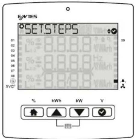

It is recommended to use the automatic SC recognition function instead of entering the values manually.
3.1.2.7 Driver Setting (on SR models only)
It is the section where the values of reactors connected to the driver are set manually.

3.1.3 Power factor correction Settings
Settings related to power factor correction are below. If your user security setting is enabled, you should enter the password before accessing the submenus.
3.1.3.1 Power factor correction Program It is the field where the power factor correction program applied is selected. The off program option must be used in the case that the user will disable power factor correction and perform it manually.
Linear program (LIN) must be selected if you want the program to start taking from the lowest step and start releasing from the lowest step.
Capacitor or reactor program (or -) is the program where power factor correction is performed automatically by using the defined capacitors and reactors. In this program, a capacitor and a reactor cannot be taken to the same phase. This protection prevents a three-phase capacitor and three phase reactor from being on the same circuit.
Capacitor and reactor combination program ( → and → ) is the program where power factor correction is performed automatically by using the defined capacitors and reactors. In this program, a capacitor and a reactor can be taken at the sometime. The type of the step taken is selected by product in the most suitable way possible without considering the types of the steps on the circuit.
The Capacitor, Reactor and SVC program is selected in the case that an external reactor driver will be used in addition to the Capacitor and Reactor combination program on SR models. In this program, the aim is to ensure zero distance to the targeted reactive power.


3.1.3.2 Power factor correction Mode It is the menu where the power factor correction process applied is selected.
Eco mode (Eco) remains within the alarm limits determined by the user to ensure the lowest contactor switching and lowest step use.
Sensitive mode (Sens) is the mode that offers the closest solution to the targeted os on available steps.
Standard mode (Std) is the mode where eco mode and aggressive mode are balanced and which is the best mode for standard use.
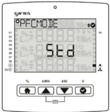
3.1.3.3 Target CosΦ It determines the cosΦ value. A value between -1,000 and +1,000 is entered, factory setting is +1,000. For the (+) region symbol, (-) region -H symbol is used.

3.1.3.4 Generator Target CosΦ If you select the parameter active for your generator program, it will make the cos phi parameter which you have entered when the generator input is enabled.

If you select `no` the wizard will finish.
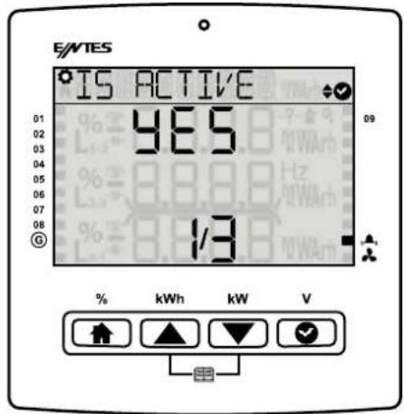
if you select "off" the steps will be switch off.

For (+) the symbol is used. For the (-) symbol is used.

3.1.3.5 Three-phase On Delay It indicates the time required for three-phase capacitor taking and three-phase reactor release. Enter a value between 1 and 1800 (in seconds). The factory setting is 10 seconds.

3.1.3.6 Three-phase Off Delay It indicates the time required for three-phase capacitor off and three-phase reactor on. Enter a value between 1 and 1800 (in seconds). The factory setting is 10 seconds.
3.1.3.7 Single phase Delay In indicates the product's time of reaction to load changes in a single phase. Enter a value between 1 and 1800 (in seconds). The factory setting is 10 seconds.
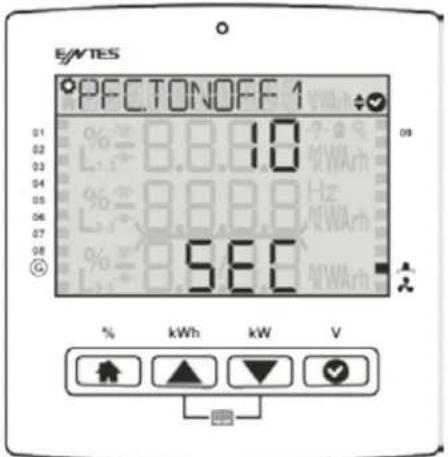
3.1.3.8 Discharge Time It is the field where the discharge time of the step is entered. If the step type is selected as Capacitor, the discharge time will indicate the minimum time after which it will be switched on after the step has been released. Discharge time must be set at the times determined by the capacitor manufacturer. If a discharge coil or contactors with discharge coil is/are used, this time might be shortened in accordance with the criteria stated by the manufacturer. Enter a value between 1 and 1800 (in seconds). The factory setting 14 seconds.

3.1.3.9 Power factor correction Manual Step It is the menu where steps are switched on/off manually.

3.1.3.10 Power factor correction Manual SVC Step It is the step where the powers of driver reactors are switched on/off manually.

3.1.3.11 Power factor correction Reading Day It is the menu where the day on which your electricity bill is defined on the product.

3.1.4 Communication Settings Menu
Communication settings of the product are made in this menu. Under “Communication Settings” menu, you will see the “Modbus Setting” menu. If your user security setting is enabled, you should enter the password before accessing the submenus.
3.1.4.1 Modbus Setting
Modbus RTU settings of the device are performed in this menu. Modbus address, bit rate and parity bit of the product are set in this menu.

Modbus Address: This parameter can be set to a value between 1 and 247. The value set must be unique on the line where the product is found. Otherwise, communication of the line, to which the product is connected, will be disrupted.

Bit Rate: This parameter can be set to one of the following values: 2400, 4800, 9600, 19200, 38400, 57600, 115200 or 256000 bps. The value of this parameter must be same as the value in the software you use to communicate with the product. Otherwise, you cannot communicate with the product.

Parity Bit: The parity bit can be set to none, odd or even. The value of this parameter must be same as the value in the software you use to communicate with the product. Otherwise, you cannot communicate with the product.

3.1.5 Alarms Menu
Alarms menu is where alarms are programmed. Step alarm, step warning values are entered as a % value. Individual alarm values can be set, Voltage, THD-I, THDV, Temperature and User Alarm. Moreover, the user can define a user-specific alarm parameter under the alarm settings, and assign alarm features for the said parameter. The product has 1 alarm relay output, except for step relays. If one of the alarm-triggering situations given above occurs, the relevant error symbol will be displayed on the screen.
3.1.5.1 Alarm Delay Time If you snooze an alarm that alarm will not be notified with the delay of time which you have entered. But in that time the notification LED continues to warn if the alarm is still active, you can see the alarms under message menu. All of the alarm's notification time starts when you press ok under notification screen.

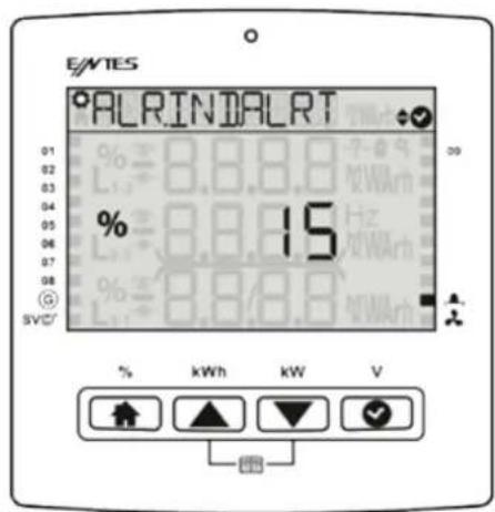
3.1.5.2 Inductive Rate Alarm This alarm occurs when the inductive power factor rate exceeds the (last 7 days) % ratio set by the user. It continues until the alarm condition is eliminated.
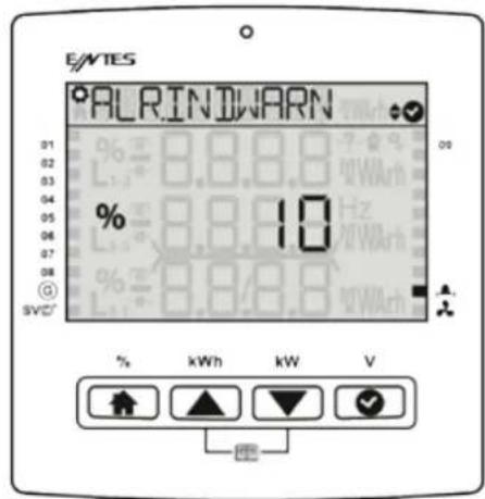
3.1.5.3 Inductive Rate Warning This warning occurs when the as power factor correction rate exceeds the rate (last 7 days) set by the user. It continues until the alarm condition is eliminated it is reset by the user.
3.1.5.4 Capacitive Rate Alarm This alarm occurs when the (last 7 days) capacitive power factor correction rate exceeds the ratio set by the user. It continues until the alarm condition is eliminated or ratios are reset by the user.
3.1.5.5 Capacitive Rate Warning This warning occurs when the (last 7 days) capacitive power factor correction rate exceeds the ratio set by the user. It continues until the alarm condition is eliminated or it is reset by the user.

3.1.5.6 Value Loss Alarm This alarm occurs if the power of you capacitor is under the limit of your alarm. Ex: your original capacity is 100 kVAr. You set the alarm %30, when value becomes to 30 kVAr it gives alarm.

3.1.5.7 Value Loss Warning This warning occurs if the power of you capacitor is under the limit of your alarm. Ex: your original capacity is 100 kVAr. You set the alarm %30, when value becomes to 30 kVAr it gives warning
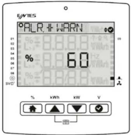
3.1.5.8 Contactor Service Life Warning This warning occurs when the rate of the switching count life exceeds the ratio set by the user. (Default value is 50.000 switching)

3.1.5.9 Contactor Service Life Alarm This alarm occurs when the rate of the contactor switching countexceeds the ratio set by the user.
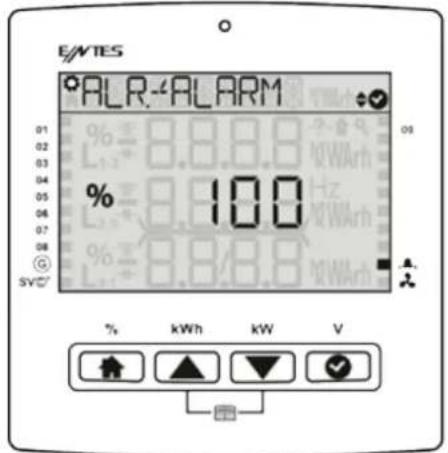
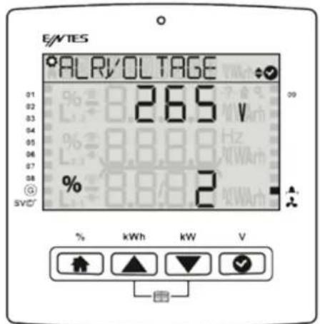
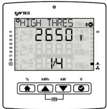
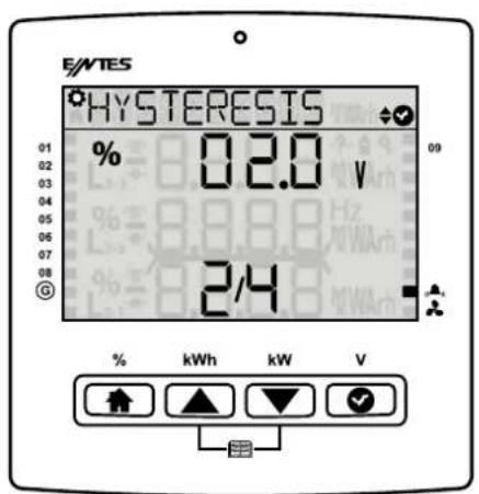
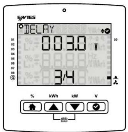
3.1.5.10 Voltage Alarm You can set voltage alarm on the device first of all you should enter the high threshold than you can set the hysteresis can be set by %, the device will recover if that amount of lower value is detected. Also on delay parameter should be set and the device checks if in that time interval the condition is available it give the alarm. You can enable step protection to protect your steps by switching them off.
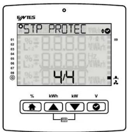
3.1.5.11 THDV Alarm You can set harmonic alarm on the device. First of all you should enter high threshold that You can set the hysteresis can be set by %, the device will recover if that amount of lower value is detected. Also on delay parameter should be set and the device checks if in that time interval the condition is available it give the alarm. If the THDI Alarm Step Protection is “Enabled” when this alarm occurs, the product will disable all steps to protect them. When the alarm condition is eliminated, it will be reset at the end of the set reset time.

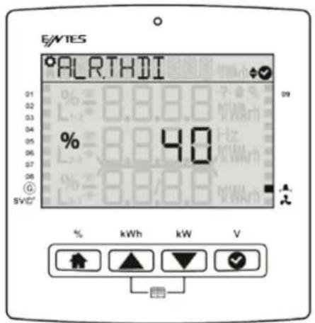
3.1.5.12 THDI Alarm If any of the Current Total Harmonic Distortion values of the phases measured by the product exceeds the upper limit set by the user, this alarm occurs as a result of the set on delay. If the THDI Alarm Step Protection is “Enabled” when this alarm occurs, the product will disable all steps to protect them. When the alarm condition is eliminated, it will be reset at the end of the set reset time.
You can set the hysteresis can be set by %, the device will recover if that amount of lower value is detected. Also on delay parameter should be set and the device checks if in that time interval the condition is available it give the alarm.
3.1.5.13 Temperature Alarm: You can set temperature alarm(Only for model's which includes internal temperature sensor). You should enter high value and low value. You can enable step protection, switch off your steps for protecting them.
3.1.5.14 Special Alarm There are Active and Passive options in the menu. You can active an alarm and program it with the wizard. Each alarm's parameters and active\passive conditions are different.

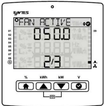
Fan Alarm: You can set a fan alarm on your device. The fan output will be activated at the fan active limit, will be passive at the fan passive limit.



3.1.6 Time Menu
It is composed of the screens where the time zone, date and time values are set. If your user security setting is enabled.
3.1.6.1 Time Zone On this screen, the user can change the time range of the product. The time zone can be set between -12:00 and 14:30 with half-an-hour intervals.

3.1.6.2 Date The user can set the current date on these screens. The change will be saved on the system without asking for conformation.

3.1.6.3 Time The user can set the current time on these screens. The change will be saved on the system without asking for conformation.

3.1.7 System Menu
In the System Settings menu, you can display information of the software, hardware and serial number of your product.
3.1.7.1 Software Version It is the menu where you can display the software version of your product.

3.1.7.2 Hardware Version It is the menu where you can display the hardware version of your product.

3.1.7.3 Serial Number It is the menu where you can display the serial number of your product.

3.1.8 Reset Menu
If your user security setting is enabled, you should enter the password before accessing the submenus.
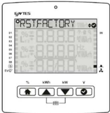
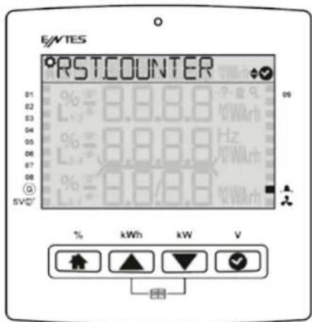
3.1.8.1 Restore Factory Settings It is the menu where you can return to the factory settings of your product. Enter the password and press "OK". If you say Yes to the confirmation question, the product will return to factory settings. All logs, settings (except time date) are reset.
3.1.8.2 Energy Counter Reset It is the menu where you can reset the energy. Enter the password and press "OK". If you say Yes to the confirmation question, the product will reset the counter data it has saved.
3.2COS Fi (Φ) Menu
3.3 Power factor correction Menu
It is the menu where you can see the inductive rate, capacitive rate and active consumptions for today, yesterday, last month and the last 7 days.
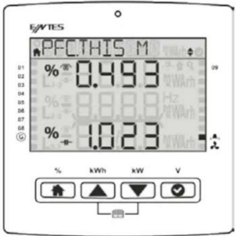
3.3.1 Power factor correction Today It is the menu where you can display the total inductive power factor correction rate, capacitive power factor correction rate values for today.

3.3.2 Power factor correction Yesterday It is the menu where you can display the total inductive power factor correction rate, capacitive power factor correction rate values for yesterday.
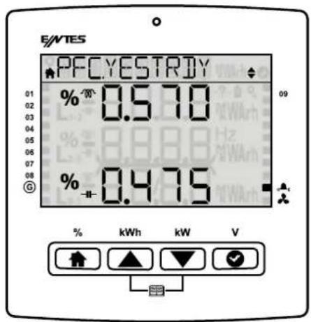
3.3.2 Power factor correction Last 7 Days It is the menu where you can display the total inductive power factor correction rate, capacitive power factor correction rate.

3.3.4 Power factor correction This Month It is the menu where you can display the total inductive power factor correction rate, capacitive power factor correction rate.

3.3.5 Power factor correction Last Month It is the menu where you can display the total inductive power factor correction rate, capacitive power factor correction rate and active.

3.4 Power
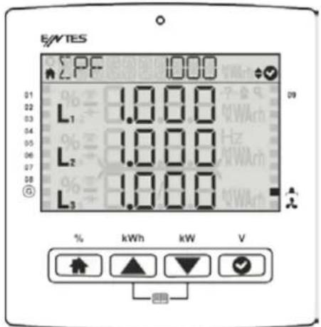
3.4.1 Power Cos You can display Cos of each phase separately. If you wait for 2 seconds in the menu, the product will show you the total Cos value in the navigation section.

3.4.2 Power Factor You can display the power factor of each phase separately. If you wait for 2 seconds in the menu, the product will show you the total PF value in the navigation section.
3.4.3 Total Power Total active, total reactive and total apparent power values are displayed on this screen.

3.4.4 Active Power Active powers on the phases are displayed on this screen. Press OK to enter the menu so you can display minimum and maximum values for the phases. If you wait for 2 seconds in the menu, the product will show you the total Active Power value in the navigation section.

3.4.5 Reactive Power Reactive powers on the phases are displayed on this screen. Press OK to enter the menu so you can display minimum and maximum values for the phases. If you wait for 2 seconds in the menu, the product will show you the total Reactive Power value in the navigation section.

3.4.6 Apparent Power Apparent powers on the phases are displayed on this screen. Press OK to enter the menu so you can display minimum and maximum values for the phases. If you wait for 2 seconds in the menu, the product will show you the total Apparent Power value in the navigation section.
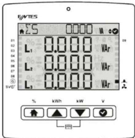
3.5 Energy It is the menu where index values are displayed.
3.5.1. Active Import Energy (AI): From the network

3.5.2. Active export energy (AE): From the network

3.5.3. Inductive reactive energy (Enr r): From the network

3.5.4. Capacitive reactive energy (Enr r): From the network

3.5.5. Apparent energy (S): From the network

If the generator input is active, other energy counters does not increase. The active energy is added to this energy meter.
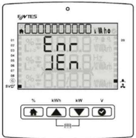
3.6 Measurements Phase-phase, phase-neutral voltages, current values of 3 phase and the frequency, temperature value measured are displayed on this screen.
3.6.1 Voltage (Phase-Neutral) At the menu phase-Neutral voltage values and at the sub menus maximum-minimum values for each phase are displayed on this screen.


Max Voltage (Phase-Neutral) Min Voltage (Phase-Neutral)
3.6.2 Voltage (Phase-Phase) Phase-Phase voltage values and at the sub menus maximum-minimum values for each phase are displayed on this screen.
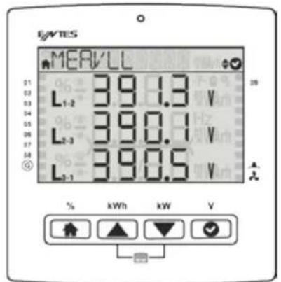

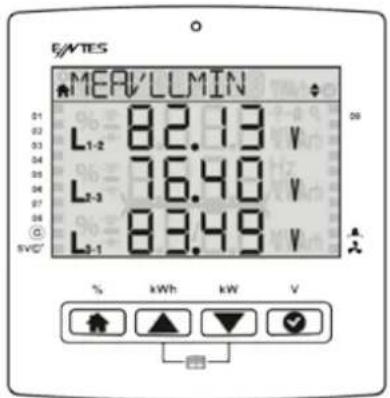
Max Voltage (Phase-Phase) Min Voltage (Phase-Phase)
3.6.3 Current (Phase-Neutral) Instantly measured current values and the Maximum and Minimum current values for each phase are displayed on this screen.


Max Current (Phase-Neutral)
Min Current (Phase-Neutral)
3.6.4 Frequency It is the menu where you can see the operating frequency of the product.

3.6.5 Temperature: You can see the internal temperature on the screen.

3.7 Harmonics
3.7.1 Current Harmonics
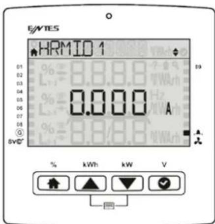
When you are in the current harmonics menu, you can press OK to proceed to the details menu and you can use Up and Down keys to display the current harmonics on the system up to the 31st harmonic.
3.7.2 Voltage Harmonics
When you are in the voltage harmonics menu, you can press OK to proceed to the details menu and you can use Up and Down keys to display the voltage harmonics on the system up to the 31st harmonic.

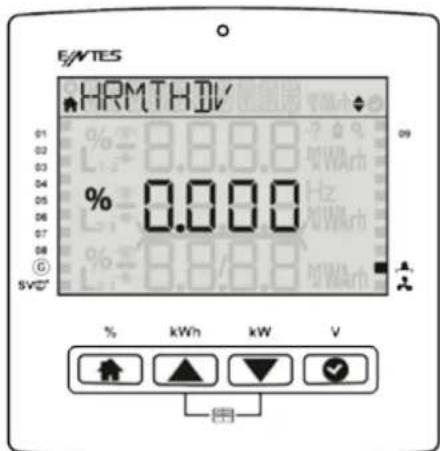
3.6.3 Current Total Harmonic Distortion (THDI)

3.6.4 Voltage Total Harmonic Distortion (THDV)
3.8 Messages
It is the menu where the alarm messages of the system are stored and where you can later display these messages. The navigation line gives you the definition of the alarm, the first line on the screen indicates if the message is an alarm or a warning. The second number in the line below shows the number of the messages on the system, and the first number shows which message amongst them you are displaying.
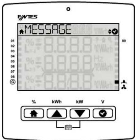
This message shows that any voltage is not connected(Example VLN1). The limit is set vnom/2 (Normally 230/2 115 volt)

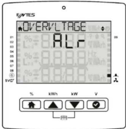
This message shows that any phase voltage exceeds the alarm value.
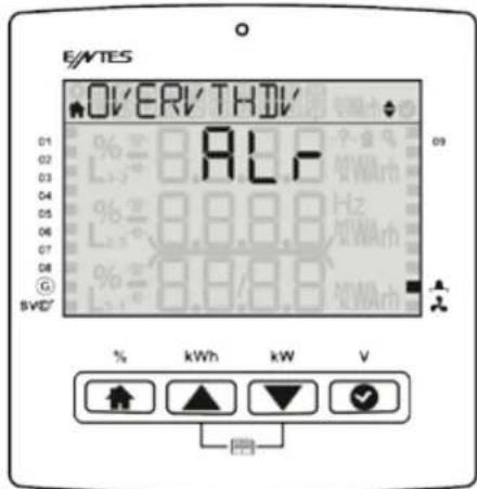
This message shows that any phase THDV (Total harmonic Distortion) value exceed the alarm limit.
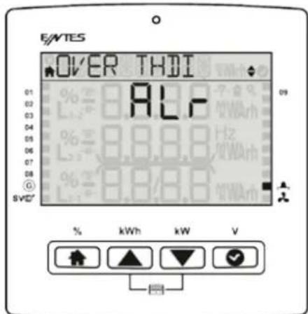
This message shows that any phase THDI (Total harmonic Distortion) exceed the alarm limit.
This message shows that the internal temperature exceed the temperature alarm limit.

This screen shows that the SVC thermic is opened.

This screen shows that the user alarm( Which you can program manually) exceed it's alarm limit.

This screen shows that the capacitive rate exceed's the alarm limit.

This screen shows that the inductive rate exceed's the warning limit.
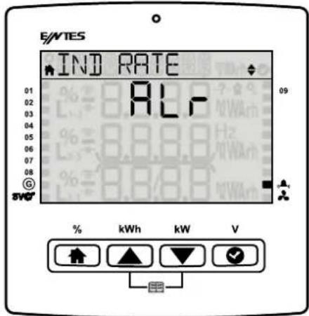
This screen shows that the capacitive rate exceed's the warning limit.

This screen shows that the inductive rate exceed's the warning limit.

This screen shows that your capacitors are not enough for your inductive reactive power. Even if the PFC switch on all the capacitors the system is on inductive side.

This message shows that your reactors are not enough for your capacitive reactive power. Even if the PFC switch on all the reactors the system is still on capacitive side.

This screen shows that your mono phase capacitors are not enough for your capacitive reactive power.
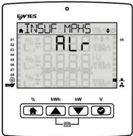
This message shows that any capacitor value is under the alarm, warning limit.


This message shows that any contactor's life exceed the alarm, warning limit.


This message shows that the capacity loss of your capacitor is exceed's the alarm, warning limit.

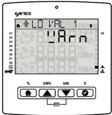
This message shows that the contactor life exceed's the alarm limit.

This message shows that the contactor life exceed's the warning limit.

4 Maintenance
Keep your product away from water and humidity. Before carrying out maintenance tasks on your product, disconnect your product from power sources and clean it with a dry cloth only. Keep your product away from water, chemical solvents etc.
It is recommended to have cable connections checked by an authorized technical personnel annually.
There is no user serviceable or repairable parts.
Please contact the dealer for all service processes.
5 Warranty Terms
Your product has 2 (two) years of warranty against manufacturing defects.
Please contact the dealer for all service processes.
The manufacturer cannot be held responsible for unwanted situations that may emerge due to failure to follow the instructions in this manual.
In case of a malfunction, the product should be repaired by the manufacturing company only.
Otherwise, the warranty will be void.
Never dismantle the product. If you do so, the warranty will be void.
6 Conformity Data
EN 50470-1: Electricity measuring equipment (a.a.) - Section 1: General rules, tests and testing conditions - Measuring equipment (class a, b and c)
EN 60068-2-1 Testing for resistance to environmental conditions - section 2-1: Tests - Test a: Cold
EN 60068-2-2 Basic environmental conditions Section 2: Tests - Test B: Dry heat
TS EN 60068-2-6 Environment test - Section 2-6: Tests - Fc tests: Vibration (sinusoidal)
EN 60068-2-30 Testing for resistance to environmental conditions - section 2-30: Tests - Test db:
Damp heat, cyclic (12 hours + 12 hours cycles)
TS EN 60529: Protection degrees ensured with cases (IP code) (on electrical equipment)
EN 60255-1: Measuring relays and protection equipment Section 1: General specifications
EN 61000-3-2: Electromagnetic compatibility (EMC) - Section 3-2: Limit values - Limit values for harmonic current transmissions (equipment input current is 16A per phase).
EN 61000-3-3 Electromagnetic compatibility (EMC)-Section 3-3: Limit values-Voltage Changes, Fluctuations and Flickering Limits on Low Voltage Supply Systems for Devices Whose Rated Current is 16 A per Phase (Included) and which are not Subject to Conditional Connection
EN 61000-4-2: Testing and measuring techniques, Electrostatic discharge immunity test.
EN 61000-4-3 Testing and measuring techniques-Radiant, radio frequency, electromagnetic field, immunity test
EN 61000-4-4 Immunity tests for electrical fast transient / sudden impact.
EN 61000-4-6 Immunity to transmitted distortions induced by RF fields
EN 61000-4-8 Immunity test for magnetic fields with mains frequency.
EN 61000-4-11 Immunity tests for voltage dips, short interruptions and voltage changes EN 55022
Information technology devices - Radio disturbance specifications - Measuring methods and limits
TS EN 61010-1 Measuring, checking and safety rules for electrical equipment used in the laboratory -
Section 1: General rules
EN 61010-1 Measuring, checking and safety rules for electrical equipment used in the laboratory -
Section 1: General rules
7 Annexes
7.1 Mechanical and Environmental Conditions
| Dimensions 144 x 144 mm | |
| Maximum Depth (Inside the Switchboard) | 60 mm |
| Panel Section Dimension 138 | x 138 mm |
| Installation Vertical Panel Installation | |
| Box Protection | IP 54 (Front Panel) |
| IP 20 (From the rear side) | |
| Display | Segment LCD |
| Color Yellow / Red / Green / White | |
| Resolution Segment | |
| Button 4x Universal Interfaces | |
| Environmental | Operating Temperature -20 / +70°C |
| Storage Temperature -30 / +80°C | |
| Maximum Relevant Humidity 95%, non-condensing | |
| Vibration 0.3 mm (2-9Hz) 1m/sn2(9-200 Hz) | |
7.2 Measuring
7.2.1 Voltage
| Parameter Unit Description Range | Sensitivity | Max Value | |||
| V1, V2, V3 | V | Phase-Neutral, Rms Voltage | 10–400 Vac | ±0.5% | 400 VAC |
| U1, U2, U3 | V | Phase-Phase, Rms Voltage | 10 – 690 Vac | ±0.5% | 690 VAC |
| Frequency | Hz | Basic Voltage Frequency | 47-63 Hz | ±0.02 Hz | 63 Hz |
| THDV | % | Total Harm. Voltage Dist. | 0 – 200% | ± 1% | 1000% |
| V Harmonic | V | Harmonic L-N Voltage Amplitude | 2. – 31. | ± 1% | 400V |
| Degree | Harmonic L-N, Phase Degree | 2. – 31. | ± 3% | 0 – 360.0 | |
| U Harmonic | V | Harmonic L-L Voltage Amplitude | 2. – 31. | ± 1% | 690V |
| Degree | Harmonic L-L Phase Degree | 2. – 31. | ± 3% | 0 – 360.0 | |
7.2.2 Phase Current
| Parameter Unit Description Range Sensitivity Max. Value | |||||
| I1, I2, I3 A Phase Current | 0.005 - 6A ±0.5% 10 kA | ||||
| THDI % Total Harm. Current Dist. 0 – 200% ± 1% | 1000% | ||||
| A | Harmonic Current Amplitude | 2. – 31. | ± 1% | 10 kA | |
| I Harmonic | Degree | Harmonic Current Amplitude | 2. – 31. | ± 3% | 0 – 360.0 |
7.2.3Power
| Parameter | Unit | Description | Range | Sensitivity | Max. Value |
| Cosφ | Cos Fi | -1.000 - +1.000 | ± 0.02 | -1.000 - +1.000 | |
| PF | Power Factor | -1.000 - +1.000 | ± 0.02 | -1.000 - +1.000 | |
| P1, P2, P3 | W | Phase Active Power | -2400 – 2400W | ± 1% | -10GW - 10GW |
| ΣP | W | Total Active Power | -7200 – 7200W | ± 1% | -30GW - 30GW |
| Q1, Q2, Q3 | VAr | Phase Reactive Power | -2400 – 2400 VAr | ± 1% | -10GVAr - 0GVAr |
| ΣQ Ind. | VAr | Total Inductive Reactive Power | 0.1 – 7200 VAr | ± 1% | 30GVAr |
| ΣQ Cap. | VAr | Total Reactive Capacitive Power | -0.1 – -7200 VAr | ± 1% | -30GVAr |
| ΣQ | VAr | Total Reactive Power | -7200 – 7200 VAr | ± 1% | -30GVAr - 0GVAr |
| S1, S2, S3 | W | Phase Apparent Power | -2400 – 2400W | ± 1% | -10GW - 10GW |
| ΣS | W | Total Apparent Power | -7200 – 7200W | ± 1% | -30GW - 30GW |
7.2.4Energy
| Parameter | Unit | Description | Range | Sensitivity | Max. Value |
| +Ea | Wh | Imp Active Energy | 0 – 2^64 | ± 1% | 2^64 Wh |
| +Er | VArh | Imp Reactive Energy | 0 – 2^64 | ± 1% | 2^64 VArh |
| -Er | VArh | Exp Reactive Energy | 0 – 2^64 | ± 1% | 2^64 VArh |
| ES | VAh | Apparent Power | 0 – 2^64 | ± 1% | 2^64 VAh |
| Esg | VAh | Generator Apparent Energy | 0 – 2^64 | ± 1% | 2^64 Vah |
7.2.4 Energy
7.2.5Min&Max Values
| Parameter | Unit Description Range Sensitivity | Max. Value | |||
| V1, V2, V3 V | Phase | -Neutral Rms Voltage 10 – 400 Vac ±0.5% 1MV | |||
| U1, U2, U3 V | Phase | -Phase Rms Voltage 10 – 690 Vac ±0.5% 1.71 MV | |||
| I1, I2, I3 A P | Phase C | Current 0.005 - 6A ±0.5% 10 kA | |||
| P1, P2, P3 | W | Phase Active Power | -2400 – 2400W | ± 1% | -10GW - 10GW |
| ΣP | W | Total Active Power | -7200 – 7200W | ± 1% | -30GW - 30GW |
| Q1, Q2, Q3 | VAr | Phase Reactive Power | 2400 – 2400 VAr | ± 1% | -10GVAr-10GVAr |
| ΣQ Ind. | VAr | Total Inductive Reactive Power | 0.1 – 7200 VAr | ± 1% | 30GVAr |
| ΣQ | VAr | Total Reactive Power | -7200 – 7200 VAr | ± 1% | -30GVAr - 30GVAr |
| S1, S2, S3 | W | Phase Apparent Power | -2400 – 2400W | ± 1% | -10GW - 10GW |
| ΣS | W | Total Apparent Power | -7200 – 7200W | ± 1% | -30GW - 30GW |
7.3 Step
| Parameter Unit Description Range Sensitivity Max. Value | |||||
| Qs1 ... Qs12 VAr | Power of Steps 999.9 kVAr + 9.999 kVAR | ±3% -999.9 | + 9.999 kVAR | ||
| Ts1 ... Ts12 - | Step Change Counter | 0 - 2^32 - 2^32 | |||
| Hs1 ... Hs12 h Step | Operating Time 0 - 2^32 ± 0.1% 2^32 | ||||
7.4 Time
| Parameter | Unit | Description | Range | Sensitivity | Max. Value |
| Hours s | Seconds | DD.MM.YYYY hh:mm:ss | - | 1 second / day | - |
7.3 Step
Manufacturer Information
Address: :Dudullu OSB 1. Cadde No: 23 34776 Ümraniye, İstanbul / TR.
Phone: :+90 (216) 313 0110
Fax: :+90 (216) 314 1615
Sales Fax: :+90 (216) 365 7171
E-mail: :satis@entes.com.tr
Web: :www.entes.com.tr
For e-bulletin subscription:ebulten@entes.com.tr
Coordinates: 40,995852 N, 29,178398 E
Entes Elektronik Cihazlar İmalat ve Ticaret A.Ş. All rights reserved © 2017

- Phase Power Factor Controllers
- Index
- Introduction...... 8
- Using the Product.... 16
- Menus 16
- Safety Warnings
- CAT III
- Introduction
- General Specifications
- RGP Product Family
- Operating Conditions
- LED Indicator
- Display Smiley View
- Front Panel View
- Key Functions
- Generator, Temperature, Alarm and Fan Indicators
- Power factor correction Shortcut Menu
- Energy Shortcut Menu
- Total Power Shortcut Menu
- V L-N Shortcut Menu
- Tutorial Mode
- Technical Specifications
- Start-up the RGP Product
- Using the Product
- Setup
- 3.Menus
- Settings Menu
- User Settings Menu
- Setup Settings Menu
- Connection Correction
- Current Transformer
- System Frequency Settings
- Auto Setup Setting
- Auto Setup SVC Setting
- Step Setting
- Driver Setting (on SR models only)
- Power factor correction Settings
- Communication Settings Menu
- Modbus Setting
- Alarms Menu
- Contactor Service Life Alarm This alarm occurs when the rate of the contactor switching countexceeds the ratio set by the user.
- Voltage Alarm You can set voltage alarm on the device first of all you should enter the high threshold than you can set the hysteresis can be set by %, the device will recover if that amount of lower value is detected. Also on delay parameter should be set and the device checks if in that time interval the condition is available it give the alarm. You can enable step protection to protect your steps by switching them off.
- Time Menu
- System Menu
- Reset Menu
- 3.2COS Fi (Φ) Menu
- Power factor correction Menu
- Power
- Energy It is the menu where index values are displayed.
- Active Import Energy (AI): From the network
- Active export energy (AE): From the network
- Inductive reactive energy (Enr r): From the network
- Capacitive reactive energy (Enr r): From the network
- Apparent energy (S): From the network
- Harmonics
- Current Harmonics
- Voltage Harmonics
- Current Total Harmonic Distortion (THDI)
- Voltage Total Harmonic Distortion (THDV)
- Messages
- Maintenance
- Warranty Terms
- Conformity Data
- Annexes
- Mechanical and Environmental Conditions
- Measuring
- Voltage
- Energy
- Step
Brand : ENTES
Model : RGP-12SR
Category : Contrôleur électrique industriel