EMR-07SL - Analyseur de réseau électrique ENTES - Free user manual and instructions
Find the device manual for free EMR-07SL ENTES in PDF.


| Product Type | Multifunction Power Meter |
| Brand | ENTES |
| Model | EMR-07SL |
| Display | 7-segment LED, 4 digits |
| Measured Parameters | Voltage, Current, Active Power, Reactive Power, Power Factor, Frequency, Energy |
| Input Voltage | 100-415V AC (L-L), 57-240V AC (L-N) |
| Current Input | via external CTs, secondary 5A or 1A |
| Frequency | 45-65 Hz |
| Communication | RS-485 Modbus RTU (optional) |
| Power Supply | 80-265V AC/DC, 50/60 Hz |
| Dimensions (mm) | 96 x 96 x 60 (panel cut-out 92x92) |
| Weight | approx. 0.3 kg |
| Operating Temperature | -10°C to +55°C |
| Protection Class | IP40 front, IP20 rear |
| Mounting | Panel mount |
| Standards | IEC 62053-21, IEC 61000 |
| Energy Accuracy | Class 1 (active), Class 2 (reactive) |
| User Interface | 4 buttons for programming and display scroll |
Frequently Asked Questions - EMR-07SL ENTES
User questions about EMR-07SL ENTES
0 question about this device. Answer the ones you know or ask your own.
Ask a new question about this device
Download the instructions for your Analyseur de réseau électrique in PDF format for free! Find your manual EMR-07SL - ENTES and take your electronic device back in hand. On this page are published all the documents necessary for the use of your device. EMR-07SL by ENTES.
USER MANUAL EMR-07SL ENTES
Safety and Warnings 3
General Specifications 3
Mechanical and Environmental Conditions 3
Standards 4
Technical Specifications 4
Connection Diagram.... 6
LED Indicator and GUI design.... 9
Key Functions 9
Measurement.... 10
Voltage 10
Current 11
Frequency 12
Cos Phi.... 12
Total Cos Phi 12
Active Power 13
Reactive Power 13
Apparent Power.... 14
Energy 14
Total Harmonic Distortion 15
Individual Harmonic Distortion.... 16
Current Harmonics 16
Total Run Hour 17
Run Hour 17
Settings.... 18
User Settings.... 18
Security Settings 18
Password Setting 19
Connection Settings 19
Connection Type 20
Frequency 21
Demand Period (Based on Model) 21
Voltage Transformer Setting 22
Current Transformer Setting.... 23
Communication Settings 23
Output Settings.... 25
Digital Input/Output Settings.... 26
User Mode 27
Alarm Settings 27
Introduction
Safety and Warnings
Caution
Failure to follow the instructions below may result in serious injuries or even death..
- Disconnect all power when installing the device.
- Do not remove the front panel while the device is connected to the mains.
- Do not clean the device with solvent or similar material. Use only a dry cloth.
- Check that the connections are correct before operating the device.
- Contact your authorized dealer if you have any questions about your device.
- The device is for panel mounting only.
- The fuse to be used must be type F and the current limit value must be 1A.
The manufacturer cannot be held responsible for unwanted situations that may emerge due to failure to follow the measures above.
Security
Read the entire operating manual before using the device.
- Connect a button or a circuit breaker between supply inlets of the product and the mains.
- This button or circuit breaker must be close to the product.
- Place a mark to indicate that this button or circuit breaker will be used to separate the product from the mains.
Warranty
The warranty period of the device is 2 (two) years. In case of a malfunction, the product should be repaired by the manufacturing company only. Otherwise, the warranty will be void.
General Specifications
- Wide supply range
- Slim design for narrow panels
• 3-Phase Voltage 3-Phase Current measurement
• 2 MB Internal Memory
• Alarm options (based on model)
• Real Time Clock(Model Base) - Run Hour
• 2x Relay Output (based on model)
• 2x digital output 2x digital input
• Modbus communication (based on model) - 96 x 96 panel mounting
Mechanical and Environmental Conditions
| Operating Conditions Value Range | |
| Dimensions 96x96 | |
| Maximum Depth(Inside the Panel) | 44.5 mm |
| Installation Panel type | |
| Display LED display | |
| Button 4 x Universal interface | |
| Storage Temperature -30 / +80°C | |
| Operating Temperature -20 / +70°C | |
| Maximum Humidity 95% (noncondensing) | |
Standards
| EN 61326,61000-6-4,61000-6-2 emc |
| EN 61010-1 Safety |
| EN 60529 Mechanic |
| EN 60068-2-1,60068-2-2 ,60068-2-30 Environmental |
Technical Specifications
| Operating Voltage (Un) 100-270 VAC (-15%+10%) | |
| Operating Frequency (f) 50-60 Hz | |
| Input Power Consumption <5 VA | |
| Measuring Inputs Power Consumption <1 VA | |
| Measuring Voltage Input (Vin) 10-300 VAC(VLN) 10-480 VAC(VLL) | |
| Measuring Current Input (lin) 0.05-5.5 A | |
| Class | |
| Voltage 1% | |
| Current 1% | |
| Frequency ±0.02 Hz | |
| cosφ ± 0.02 | |
| Demand Time Adjustable | 60/120/300/600/1200/1800/3600 sec |
| Communication (Insulated) 4kV | |
| Baud Rate Adjustable 2400/ 4800/ | 9600/19200/38400/57600/115200 |
| Address Adjustable 1-257 | |
| Parity Adjustable Single/Double | |
| Relay Ouputs 2x (5A 250 VAC/ 1250VA) | |
| Internal memory | 2MB |
| Connection | 3P3W, 3P4W, Aron, 3P3W(B), 3P4W(B) |
| Ambient Temperature | -20+70°C |
| Storage Temperature | -30+80°C |
| Humidity | 95% |
| Indicator | LED Display |
| Dimensions | 96x96x44.5 |
| Device Protection Class Protection class Inside panel: IP20Protection class Outside panel: IP51 | |
| Parameter Unit Description Range Sensitivity Maximum | Value | ||||
| Voltage | |||||
| V1, V2, V3 V | Phase- | Neutral, Rms Voltage 30-300 VA | C 1% 6 MV | ||
| U1, U2, U3 V | Phase- | Phase, Rms Voltage 30-480 VAC | C 1% 9.6 MV | ||
| Frequency Hz | Voltage | Frequency 50-60 Hz ±0.02 Hz | 60 | ||
| Current | |||||
| I1, I2, I3 A Phase Current | 0.05-5.5 A | 1% 10kA | |||
| Power | |||||
| Cosφ | Cos Phi | -1.000 - +1.000 | ± 0.02 | -1.000 - +1.000 | |
| PF | Power Factor | -1.000 - +1.000 | ± 0.02 | -1.000 - +1.000 | |
| P1,P2,P3 | W | Phase Active Factor | 1% | 9999 M | |
| ΣP | W | Total Active Power | 1% | 9999 M | |
| Q1,Q2,Q3 | VAr | Phase Reactive Power | 2% | 9999 M | |
| ΣQ Ind. | VAr | Total Inductive Reactive Power | 2% | 9999 M | |
| ΣQ Cap. | VAr | Total Reactive Capacitive Power | 2% | 9999 M | |
| ΣQ | VAr | Total Reactive Power | 2% | 9999 M | |
| S1,S2,S3 | VA | Phase Axpparent Power | 2% | 9999 M | |
| ΣS | W | Total Apparent Power | 2% | 9999 M | |
| Harmonic | |||||
| THDV | % | Total Harmonic Voltage Distortion | 0 – 200% | 1% | 1000% |
| V Harmonic | V | Harmonic L-N Voltage Amplitude | 2-31. | 1% | 1MV |
| U Harmonic | V | Harmonic L-L Phase Voltage | 2-31. | 1% | 1.71 MV |
| THDI | % | Total Current Harmonic Distortion | 0 – 200% | 1% | 1000% |
| I Harmonic | A | Harmonic Current Amplitude | 2-31. | 1% | 10kA |
| Energy | |||||
| +Ea | Wh | Active Import Energy | 1% | 9999999.9 M | |
| +Er | VArh | Inductive Reactive Energy | 2% | 9999999.9 M | |
| -Er | VArh | Inductive Capacitive Energy | 2% | 9999999.9 M | |
| ES | VAh | Apparent Energy | 2% | 9999999.9 M | |
| Esg | VAh | Generator Energy | 2% | 9999999.9 M | |
Technical Drawing


Connection Diagram

Terminal Structure;
| Connection Range Klemens Tipi | |||
| 1 Voltage Inputs 3 x 10 – 480 VAC 50/60Hz 4 x 7.62 mm socket | 2.5 mm^2, 4 mm^2 TD | ||
| 2 Relay Outputs 2 x 250 VAC 5A 1250 VA 4 x 5.08 mm socket | 2.5 mm^2 / 4 mm^2 TD | ||
| 3 Auxiliary supply input 100-270 VAC / 50-60 Hz 3 x 5.08 mm socket | 2.5 mm^2 / 4 mm^2 TD | ||
| 4 Current Inputs 3 x 0.05 – 5.5A / AC 50-60 Hz 6 x 5.08 mm socket | 2.5 mm^2 / 4 mm^2 TD | ||
| 5 Digital input/output 5-24 VDC / Max 30 VDC 6 x 3,81 mm / 1,5 mm | ^2 / 2,5 mm^2 TD | ||
| 6 RS-485 Max. ±12V | 3 x 3.81 mm socket | 1.5 mm^2 / 2.5 mm^2 TD | |
1. 3P4W (Three-Phase Four-Wire) Connection
In this type of connection, four voltages and three currents connections are made.

2. 3P3W (Three-Phase Three-Wire) Connection
In this type of connection, three voltages and three currents connections are made.

3. Aron Connection without Neutral
In this type of connection, three voltages and two currents connections are made.

4. 3P4W BLN (Three-Phase Four-Wire Balanced) Connection
In this type of connection, four voltages and one current connections are made. The device displays the value measured at the current input connected to the first phase on the screen of the same value for other phases.

5. 3P3W BLN (Three-Phase Three-Wire Balanced) Connection
In this type of connection, three voltages and one current connections are made. The device displays the value measured at the current input connected to the first phase on the screen of the same value for other phases.

Connection types may vary depending on the device model.
LED Indicator and GUI design

Key Functions
| Phase 1 / 2 / 3 LEDs | L1 L2 L3● ● ● | It informs you that voltage is taken from the phases. (e.g. LED L1 lights up if voltage is being taken from phase L1.) |
| VLN Measurement LED | VLN | It lights up when the screen showing phase-neutral voltages is on |
| VLL Measurement LED | VLL | It lights up when the screen showing phase-phase voltages is on |
| Current Measurement LED | I | It lights up when the screen showing phase currents is on |
| PF LED | PF | It lights up when the screen is on |
| cosj Measurement LED | cosφ | It lights up when the screen showing phase cosφ is on |
| Active Power Measure LEDs | W | It lights up when the screen showing active power is on. |
| Reactive Power Measure LED | VAr | It lights up when the screen showing reactive power is on. |
| Apparent Power Measure LED | VA | It lights up when the screen showing apparent power is on. |
| Energy | ENR | It lights up when energy is shown. |
| Harmonic Measurement LED HAR It lights up when the | screen showing harmonic values is on. | |
| THD Measure LED | THD | It lights up when the screen showing THD values is on. |
| Digital Input 1 LED | IN1 | It lights up when it gets pulse or digital control input command. |
| Digital Input 2 LED | IN2 | It lights up when it gets pulse or digital control input command. |
| ○ | It lights up when there is a phase sequence error. | |
| Latch Symbol | LAT | It lights up when the alarm is activated and continues to light up until you press and hold the 3rd-second key after the alarm is deactivated |
| Unit Symbol | ||
| Percentage Symbol | % | Indicates the percentage symbol. |
| Second Symbol | S | Indicates the Second Symbol |
| Total Symbol | Σ | Indicates the Total Symbol |
| Language Navigation LED | A‡ | It lights up when the screen where the menu and display language of the device can be set is on |
| Frequency Symbol | Hz | Indicates the Frequency Symbol |
| Hour Unit Symbol | h | Indicates the Hour Unit Symbol |
| Maximum Symbol | MAX | Indicates the Maximum Symbol |
| Minimum Symbol | MIN | Indicates the Minimum Symbol |
| Demand Symbol | DMD | Indicates the Demand Symbol |
| Weight Unit Symbol | k | Indicates the Weight Unit Symbol |
| Lock Navigation LED | It lights when the main setting screen of the password protection values is on | |
| Network Navigation LED | ΔΔ | It lights up when the screen where the network settings of the meter are completed is on |
| Transformer Navigation LED | ◎ | It lights up when the screen with voltage transformer and current transformer master view and settings is on |
| Communication Navigation LED | MOD | It lights up when the screen where the Modbus Communication settings are displayed and changed is on |
| Input Output (I/O) LED | I/O | The input on the LED device lights up while the output settings are being made. |
| Alarm Navigation LED | It lights up when the main screen to access alarm settings is open | |
| Reset Navigation LED | RST | It lights up when the setting screen where Min, Max, Demand values are deleted is on |
| Info Navigation LED | ➀ | It lights up when the menu for displaying information such as software, hardware versions, serial number, date, time of the device is on |
| Relay 1 Output LED | RLY1 | It lights up when the relay output is active |
| Relay 2 Output LED | RLY2 | It lights up when the relay output is active |
| Digital Output 1 LED | OUT1 | It lights up when it sends a pulse or digital output control command |
| Digital Output 2 LED | OUT2 | It lights up when it sends a pulse or digital output control command |
Measurement
Voltage
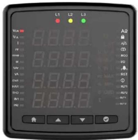
This screen shows the phase-neutral voltage values for each phase. You can see Min Voltage (Phase-Neutral) and Max Voltage (Phase-Neutral) values by pressing the OK button. Depending on the connection type in the Phase-Neutral voltage (3P3W, 3P3W balance and Aron), this screen will not be displayed.


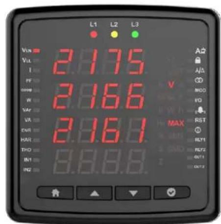
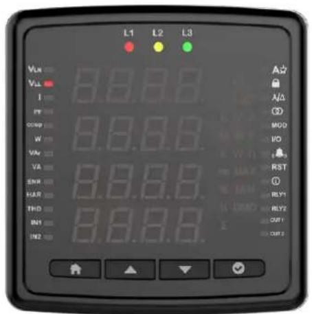
This screen shows the phase-phase voltage values for each phase. You can see Min Voltage (Phase-Phase) and Max Voltage (Phase-Phase) values by pressing the OK button.


Current
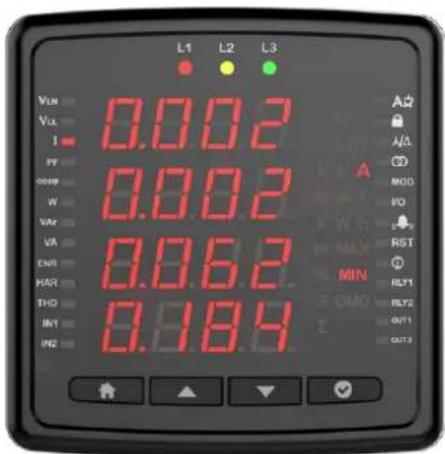
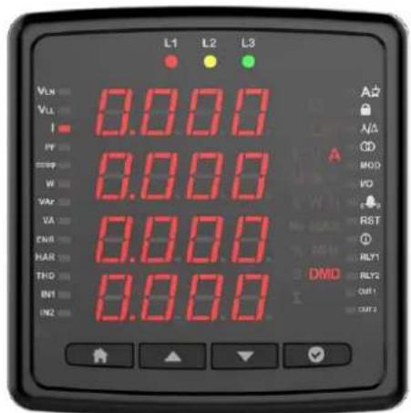
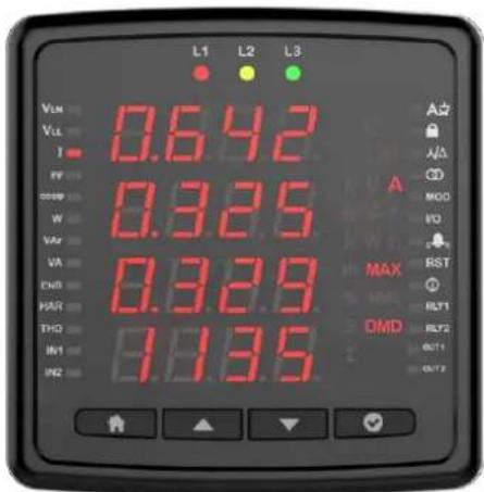
Instantly measured current values for each phase are displayed on this screen. You can see Min Voltage (Phase-Neutral), Max Current (Phase-Neutral), Demand (Phase-Neutral) and Max Demand (Phase-Neutral) values by pressing the OK button.
The currents of the phases are shown in the first 3 lines on the current screens. In line 4, the calculated neutral current is shown.


Frequency
You can see the operating frequency of the device on this screen.

Cos Phi
You can see cos phi values of each phase separately on this screen.

Total Cos Phi
You can see total cos phi values on this screen.

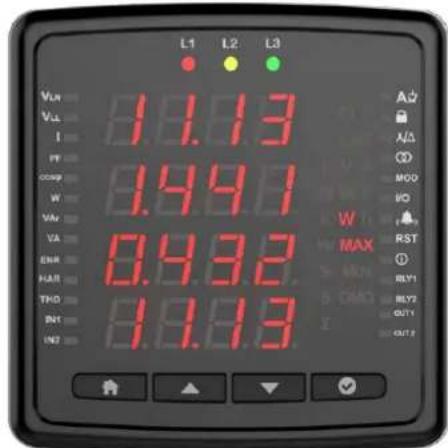
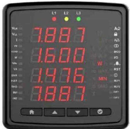
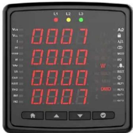
Active Power
Active powers in phases are displayed on this screen. You can view the minimum, maximum, demand and max demand values for the phases you entered in the menu with the OK button.


Reactive Power
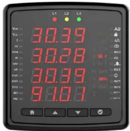
This screen shows reactive powers in phases. You can view the minimum and maximum values of the phases you entered in the menu with the OK button.


Apparent Power
In this screen, apparent powers are shown. When you enter the menu with OK button, you can view the minimum and maximum values of the phases.


Energy
Energy menus are shown on this screen. You can see Active Import, Active Export, Generator Active, Inductive Reactive, Capacitive Reactive, Apparent and Generator Apparent Power with the down button.


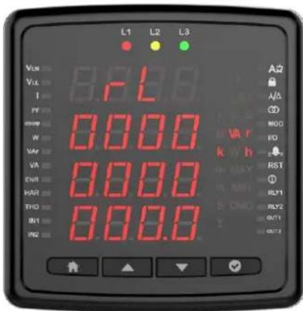
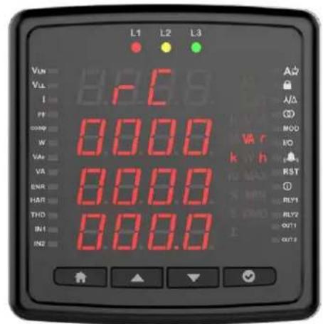


Total Harmonic Distortion
In this menu, you can view the Voltage and Current THD values by scrolling with the down button.


Individual Harmonic Distortion
In this menu, after selecting F-F or F-N and pressing the OK button, you can view the voltage harmonics in the system up to the 31st harmonic by using the up and down button.


After pressing the OK button in this menu, you can view the current harmonics in the system until the 31st Harmonic by using the up and down button.
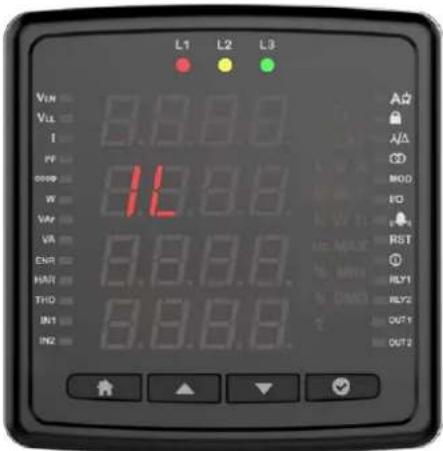
It is the screen on which the run hour of this device is displayed. You can view the time it has worked since the first power-up on the screen. The value on the screen increases by 1 in 3.6 seconds. If you multiply the value on the screen by 3.6, you can reach the total operating time.


Run Hour
This screen works according to the condition of the parameters selected from the settings. It is the counter that will run when the parameters exceed the threshold value entered by the user. The value on the screen increases by 1 in 3.6 seconds. If you multiply the value on the screen by 3.6, you can reach the total operating time.
Parameters (Depends on device)
- Current
- Generator
- P Max DMD
- Toplam P
- P DMD
• P
• I DMD
• IL
- Current demand

Settings
Press and hold OK to access the settings menu. If you wish to do something under the Settings menu or change the settings, press OK to go to menu details and change Product or User settings under the Settings menu. In the Settings menu, the symbols in the right corner of the screen indicate which setting you are in.
User Settings
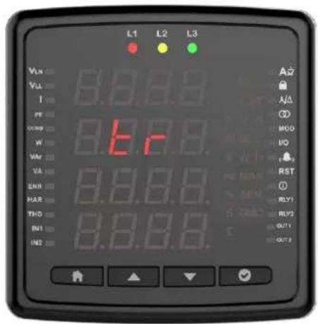
This is the menu where you can set the language for your device. You can choose between Turkish, English, German, French and Spanish language options with the up and down buttons.
Security Settings
You can activate and deactivate the password protection with the OK button in the safety setting. You should select one of the options: Yes/No. If Yes is selected, the password screen will be displayed each time you change the setting. If No is selected, the password screen will not appear.

Password Setting
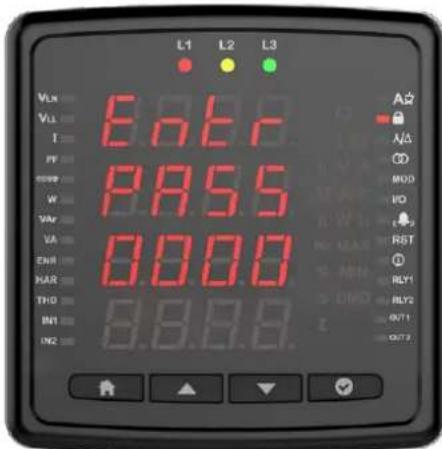
On this screen, you can set the password that you will use for the security of the device. The current password is entered on the first screen.
If it is entered correctly, the screen for entering the new password will be displayed. The screen for re-entering the password is displayed to confirm the new password. As with all settings, the saving confirmation must be set to yes when exiting the settings for the new password to be active.
Connection Settings
In this screen, you can press the OK button to configure the connection settings.

Connection Type
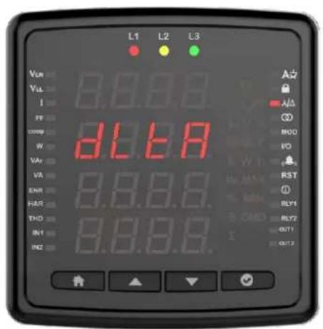
You can configure the connection types in this menu.


Frequency
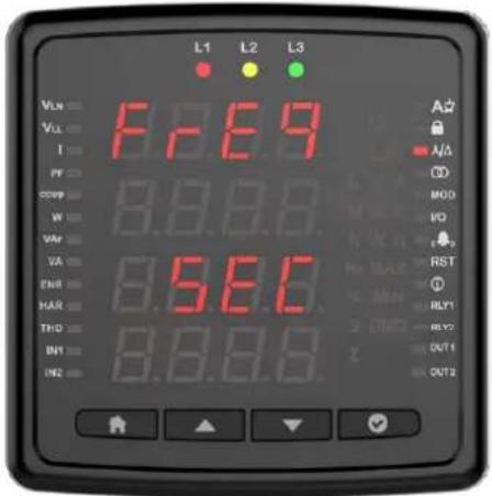
You can set the frequency value of the network from this screen.

Demand Period (Based on Model)
You can specify the demand period of your device from this menu.


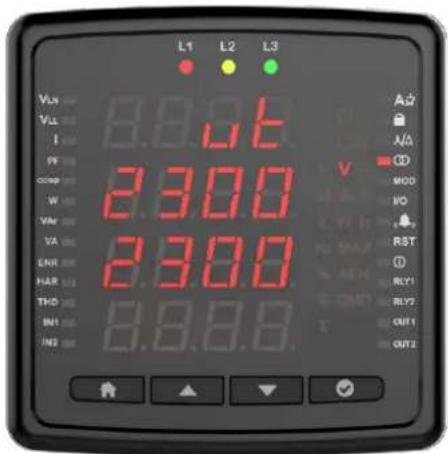
Voltage Transformer Setting
In this screen, you can configure the voltage transformer settings. If you are using a voltage transformer, you must set the setting to on and then enter the primary and secondary values.


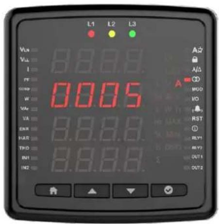
Current Transformer Setting
It is the menu in which the primary and secondary values for the current transformer are entered. You will be prompted to enter CT Primary and CT Secondary values respectively.



Communication Settings
Communication and Modbus RTU settings of the device are made in this menu. Modbus address, bit rate, parity bit settings of the device are made in this menu (For models without communication, this screen will not be available).
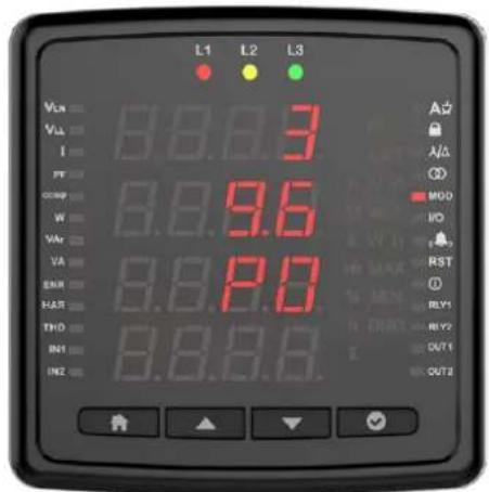
Modbus Address: This parameter can be set to a value between 1 and 247. The value set must be unique on the line where the product is found. Otherwise, communication of the line, to which the product is connected, will be disrupted.
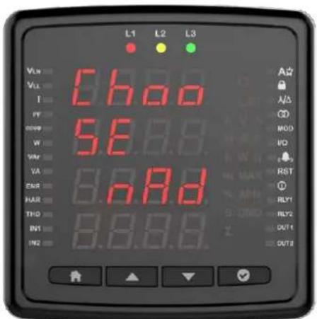

Bit Rate: This parameter can be set to one of the following values: 2400, 4800, 9600, 19200, 38400, 57600, 115200 or 256000 bps. The value of this parameter must be the same as the value in the software you use to communicate with the product. Otherwise, you cannot communicate with the product.


Parity Bit: The parity bit can be set to N/A, single or double. The value of this parameter must be the same as the value in the software you use to communicate with the product. Otherwise, you cannot communicate with the product.


Output Settings
On this screen, you can configure the output settings of the device.
Relay 1
Press the OK button to configure the relay setting.
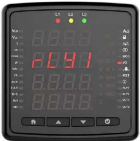
Then select the setting parameter.

Setting parameter can be selected as Relay or RS-485. If the setting is selected as a relay, the relay is activated when an alarm condition occurs (if the alarm output is assigned as a relay). If RS-485 is selected, the relay can be switched on and off via MODBUS.
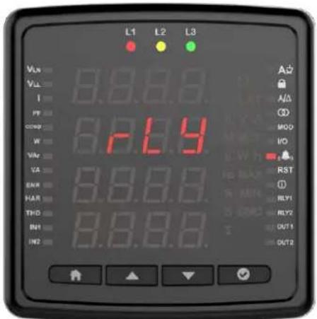

Digital Input/Output Settings
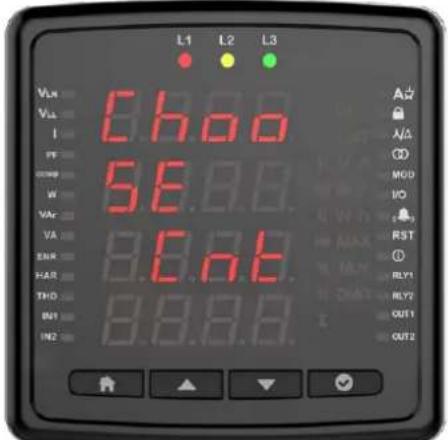
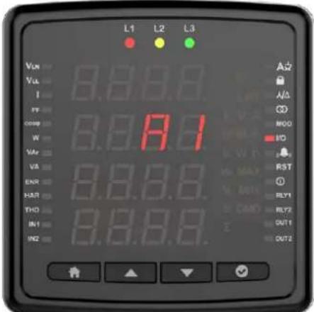
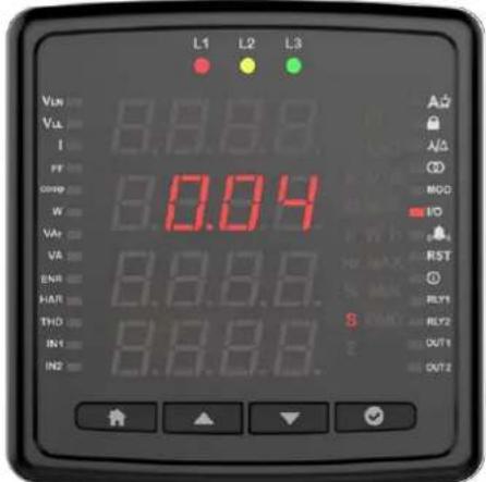
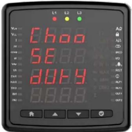
You can set the digital input setting as Generator or pulse. Press OK to configure the relay setting.


When selected as pulse, enter the parameter / rate / time / gap time to count for the pulse.



User Mode
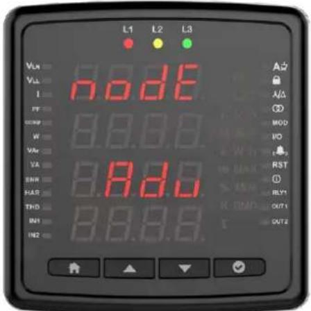
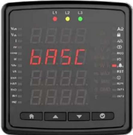
It is the screen where the user mode is selected. The user mode can be selected as simple or advanced. In the advanced user mode, the following parameters are activated (varies by parameter). Hysteresis is only available in the measurement parameters.
• T_on
• T_off
- Hysteresis
- Output function
Alarm Settings
Press the OK button to enter the alarm settings.

Custom alarm
Press the OK button to program a custom alarm. Any of 8 custom alarms appears on the screen when setting the alarm. The alarm number is displayed on the screen.

Then select a parameter. Parameter selection varies by device model. You can set alarm by selecting Voltage, Current, Current demand, Frequency, Cos Phi, Total work time and work time.
For example, the voltage alarm setup is as follows.


Press the OK button to make an operation selection.
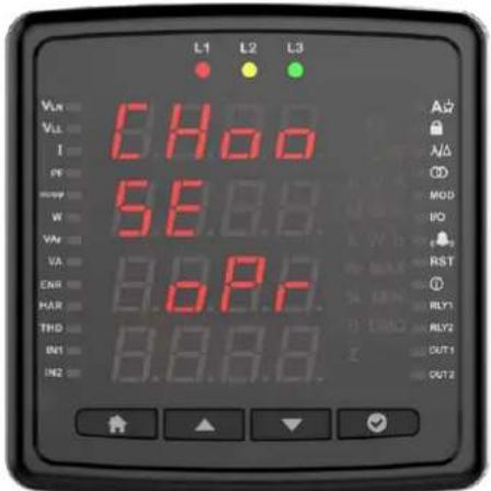
Select the large or small operation.

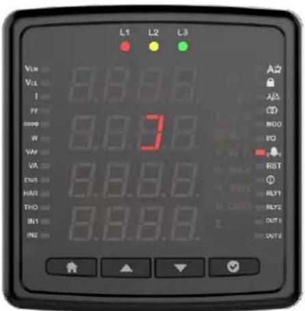
Then press the OK button and enter a value.

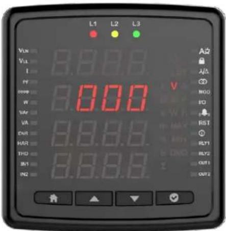
Enter the hysteresis value and press the OK button.


Enter the on delay and press the OK button.
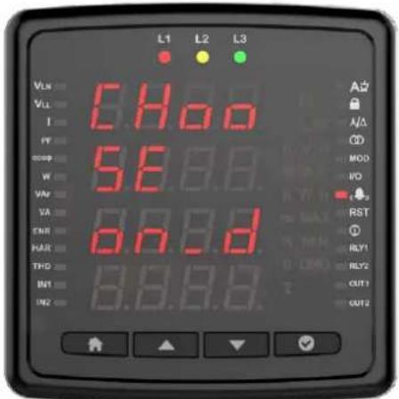
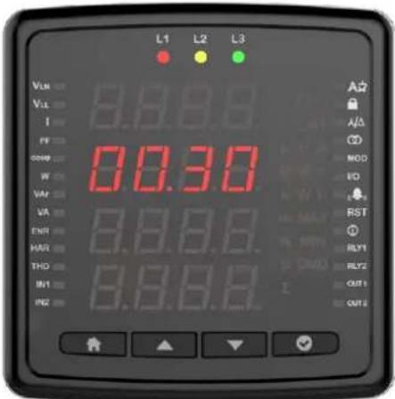
Enter the off delay and press the OK button.
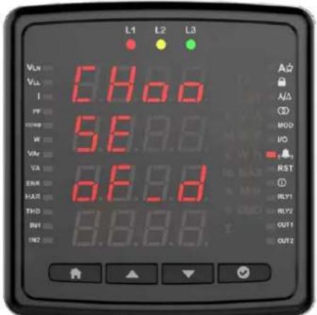

Select the output feature on the device with output options.

When this option is selected, there is no output on the device.

When Rly 2 is selected, relay number 2 is activated in case of alarm.

When Rly 1 is selected, relay number 1 is activated in case of alarm.

Press the OK button to select the function.
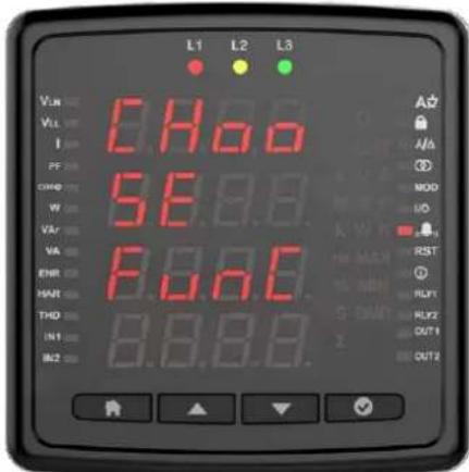
In standard mode, the relay is activated when an alarm occurs.

In Latch mode, the relay is activated when the alarm actuates, but when the alarm disappears, the relay remains on. You must hold the down button to return the relay to its normal state.

In Inverse mode, the relay is released if it is activated, or it is activated if it is released. When the status of a relay is selected as inverse for any alarm, that relay will only operate as inverse for all assigned alarms.

Reset
On this screen, you can reset the device to factory settings by pressing the OK button.


On this screen, you can reset the work time by pressing the OK button.
On this screen, you can reset the MAX Demand by pressing the OK button.

On this screen, you can reset the MAX by pressing the OK button.
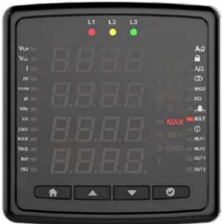
On this screen, you can reset the MIN by pressing the OK button.

On this screen, you can reset the work time by pressing the OK button. The total work time cannot be reset.

Run Hour
In this menu, you can set the work time for Current or Current Demand.



Clock Date Settings
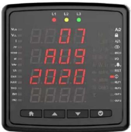
Press the OK button to set the date. Enter year, month and day information.

Press the OK button to set the clock. Set the region selection hour, minute and second settings.


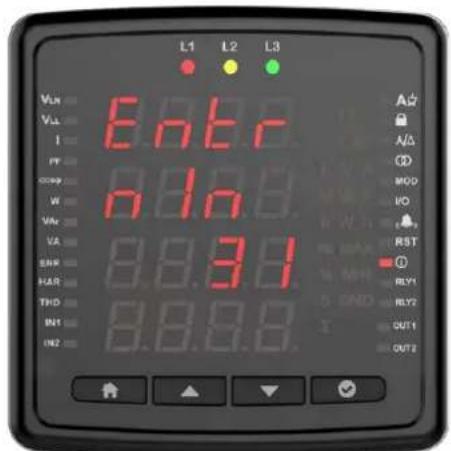

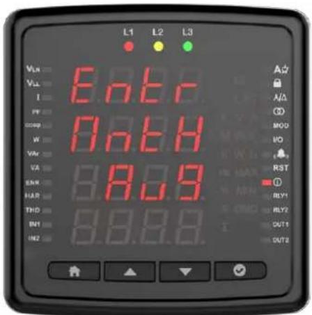
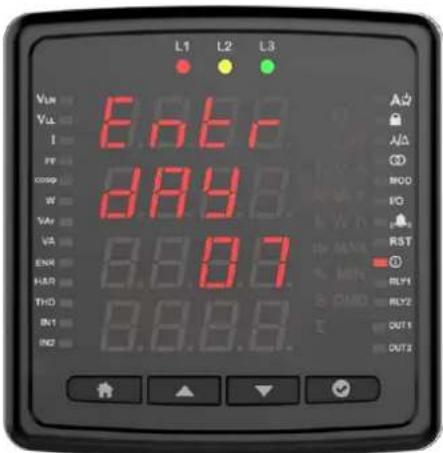
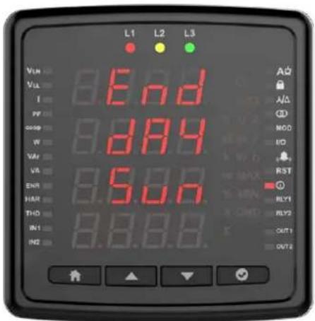
Press the OK button to configure the summer and winter time settings. Choose from European, American or special options.


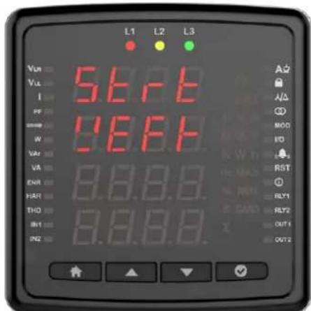
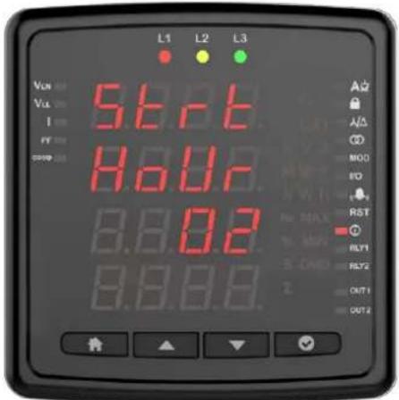
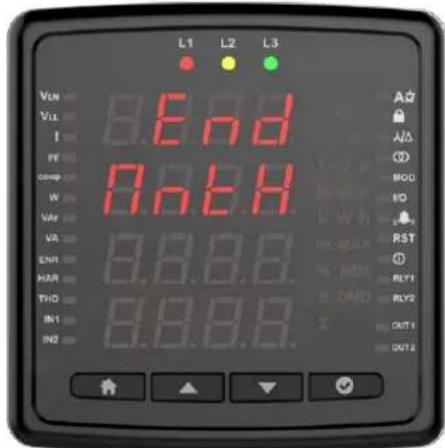
If a special selection has been made, set the start month / start week / start day / start time / end month / end week / end day / end time.





Info
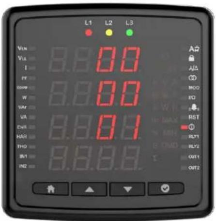
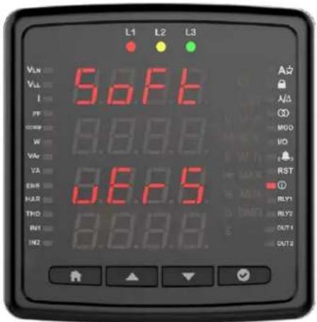
In the Info menu, you can view the following information about the device.
Hardware Version

Software Version

Serial No


When an alarm occurs on your device, the alarm appears on the screen. You can delay the alarms by pressing the OK button for the duration of the delay time setting. When critical alarms occur, Relay 1 is activated.
No Voltage is measured
It occurs when any phase has no voltage. The number of the voltage-free phase is shown on the screen. In addition, the bulb of the voltage-free phase in the signal bulbs does not light upon the device.

Phase Sequence
It occurs when the phases are not connected in the correct order.

ENTES Elektronik Cihazlar Imalat ve Ticaret A.S.
Adr: Dudullu OSB; 1. Cadde; No:23 34776
Umraniye - ISTANBUL / TURKIYE
Tel: +90 216 313 01 10 Fax: +90 216 314 16 15
E-mail: contact@entes.eu Web: www.entes.eu
Call Center Technical Support: 0850 888 84 25
- Introduction
- Safety and Warnings
- Caution
- Security
- Warranty
- General Specifications
- 3P4W (Three-Phase Four-Wire) Connection
- 3P3W (Three-Phase Three-Wire) Connection
- Aron Connection without Neutral
- 3P4W BLN (Three-Phase Four-Wire Balanced) Connection
- 3P3W BLN (Three-Phase Three-Wire Balanced) Connection
- LED Indicator and GUI design
- Measurement
- Voltage
- Current
- Frequency
- Cos Phi
- Total Cos Phi
- Active Power
- Reactive Power
- Apparent Power
- Energy
- Total Harmonic Distortion
- Individual Harmonic Distortion
- Run Hour
- Settings
- User Settings
- Security Settings
- Password Setting
- Connection Settings
- Connection Type
- Demand Period (Based on Model)
- Voltage Transformer Setting
- Current Transformer Setting
- Communication Settings
- Output Settings
- Relay 1
- Digital Input/Output Settings
- User Mode
- Alarm Settings
- Custom alarm
- Reset
- Clock Date Settings
- Info
- No Voltage is measured
- Phase Sequence
Brand : ENTES
Model : EMR-07SL
Category : Analyseur de réseau électrique