
Window Awning - Window Blinds DOMETIC - Free user manual and instructions
Find the device manual for free Window Awning DOMETIC in PDF.


| Brand | Dometic |
| Model | Window Awning |
| Product Type | Window Awning |
| Material | Acrylic fabric, aluminum frame |
| Color | Various color options available |
| Dimensions (Width x Projection) | 2000 mm x 1500 mm (78.7 in x 59.1 in) |
| Weight | Approximately 8 kg (17.6 lbs) |
| Mounting | Wall mount or roof mount |
| Operation | Manual crank mechanism |
| Main Functions | Provides shade and protection from sun and light rain |
| UV Protection | UPF 50+ fabric blocks 98% of UV rays |
| Water Resistance | Water-repellent fabric, not fully waterproof |
| Wind Resistance | Designed for wind speeds up to 20 mph (32 km/h) |
| Retractable | Yes, manual retraction |
| Included Hardware | Mounting brackets, crank handle, installation screws |
| Maintenance | Clean with mild soap and water; avoid abrasive cleaners |
| Safety | Do not use in high winds; ensure proper installation |
| Spare Parts Availability | Replacement fabric, crank handle, and brackets available |
| Repairability | Modular design allows easy replacement of parts |
| Warranty | 2-year limited warranty |
Frequently Asked Questions - Window Awning DOMETIC
User questions about Window Awning DOMETIC
0 question about this device. Answer the ones you know or ask your own.
Ask a new question about this device
Download the instructions for your Window Blinds in PDF format for free! Find your manual Window Awning - DOMETIC and take your electronic device back in hand. On this page are published all the documents necessary for the use of your device. Window Awning by DOMETIC.
USER MANUAL Window Awning DOMETIC
RECORD THIS INFORMATION FOR FUTURE REFERENCE:
FRTA Model Number
FRTA Serial Number
Hardware Model Number
Hardware Serial Number
Date Purchased
Retailer / Qualified Installer
INSTALLATION INSTRUCTIONS
UNIVERSAL SERIES
PATIO AWNING
HARDWARE
8273000, 8483000, 8430000, 8440000
FRTA
Read these instructions carefully. These instructions MUST stay with this product.
INTRODUCTION
This awning (hereinafter referred to as "awning," or "product") is designed and intended for use on RVs with straight sides. For curved sides, please see the separate Hardware List in the Dealer Service Manual for the appropriate model.
This awning can be installed by one person with brief help from additional personnel. Use these instructions to ensure correct installation, function, and operation of the product.
Dometic Corporation reserves the right to modify appearances and specifications without notice.
TABLE OF CONTENTS
INTRODUCTION 2
DOCUMENT SYMBOLS 2
IMPORTANT SAFETY INSTRUCTIONS....3
A. Recognize Safety Information 3 B. Understand Signal Words....3 C. Supplemental Directives....3 D. General Safety Messages ....3
GENERAL INFORMATION....3
A. Optional Components....3
SPECIFICATIONS......4
A. Hardware Dimensions 4
PREPARE FOR INSTALLATION 5
A. Door Roller And Edge Guard (Optional) 5 B. Prepare Awning Rail 5 C. Prepare Awning For Installation....5 D. Determine Awning Location....6
INSTALL AWNING 7
A. Install LED Light Switch (If Applicable)....7 B. Insert Awning Fabric Into Awning Rail....8 C. Install Top Mounting Brackets....8 D. Install Bottom Mounting Brackets....9 E. Install Stop Bolts....10 F. Release Preset Tension....11 G. Secure Awning Fabric To Awning Rail....11 H. LED Light Connections (If Applicable)....12
VERIFY INSTALLATION....12
A. Test Operation....12 B. Secure Awning For Travel....12 C. Keep Literature....12
DOCUMENT SYMBOLS

Indicates additional information that is NOT related to physical injury.

Indicates step-by-step instructions.
IMPORTANT SAFETY INSTRUCTIONS
This manual has safety information and instructions to help you eliminate or reduce the risk of accidents and injuries.
A. Recognize Safety Information

This is the safety alert symbol. It is used to alert you to potential physical injury hazards. Obey all safety messages that follow this symbol to avoid possible injury or death.
B. Understand Signal Words
A signal word will identify safety messages and property damage messages, and will indicate the degree or level of hazard seriousness.
WARNING indicates a hazardous situation that, if NOT avoided, could result in death or serious injury.
CAUTION indicates a hazardous situation that, if NOT avoided, could result in minor or moderate injury.
NOTICE is used to address practices NOT related to physical injury.
C. Supplemental Directives

Read and follow all safety information and instructions to avoid possible injury or death.
Read and understand these instructions before installing, using, servicing, or performing maintenance on this product.
Incorrect installation, operation, servicing, or maintaining of this product can lead to serious injury. Follow all instructions.
The installation MUST comply with all applicable local and national codes, including the latest edition of the following standards:
U.S.A.
• ANSI/NFPA70, National Electrical Code (NEC) • ANSI/NFPA 1192, Recreational Vehicles Code
CANADA
- CSAC22.1, Parts I & II, Canadian Electrical Code • CSA Z240 RV Series, Recreational Vehicles
D. General Safety Messages
⚠ WARNING Failure to obey the following warnings could result in death or serious injury:
- This product MUST be installed or serviced by a qualified service technician.
- Do NOT modify this product in any way. Modification can be extremely hazardous.
- IMPACT OR CRUSH HAZARD. This product should be installed in a controlled environment (inside). Do NOT install product during windy conditions, or when wind is expected. Otherwise, product could move unpredictably, become unstable, and could detach, bend, or collapse.
GENERAL INFORMATION
A. Optional Components
(1) 830304 Door Roller Kit (1) 830304.003 Door Roller Kits (50 Pack) (1) 3109623.003 Top Bracket Spacer (1) 3109623.550 Top Bracket Spacers (50 Pack) (1) 3104781.004 Bottom Spacer Kit (1 Pair) (1) 3104781.103 Bottom Spacer Kits (10 Pair)
SPECIFICATIONS
A. Hardware Dimensions
| MODELSERIES | 8430000.401# | .001 | .002 | 8273000.405# | 8273000.407# | *8273000.408# |
| 8273000.401#.501#.502# | ||||||
| HeightRange | 54" - 61" | 76" - 86" 64" | - 76" 78" - 91" 94" | - 107" | Short 64" - 76" | |
| Tall 76" - 86" | ||||||
| Main ArmLength | 49" 73" 61" | 76" 92" | Short 61" | |||
| Tall 73" | ||||||
| AdjustableArm Length | 45" 57" 57" | 72" 72" | Short 57" | |||
| Tall 57" | ||||||
| Main RafterLength | 43 1/2" 66" | 54" 71" 71" | Short 54" | |||
| Tall 66" | ||||||
| SecondaryRafterLength | 42 1/2" 32 1" | 44 1/2" 53 1/2" | 53 1/2" | Short 44 1/2" | ||
| Tall 32 1/2" | ||||||
| Duty | .00(X) | Standard | ||||
| .40(X)# | ||||||
| .10(X) | Heavy | |||||
| .50(X)# | ||||||

Standard Duty hardware may be used if awning FRTA is 21' wide (or less).
Heavy Duty hardware MUST be used if awning FRTA is greater than 21' wide.
*Models 8273000.(X)08# and 8483000.(X)08# hardware has (1) Short and (1) Tall Arm/Rafter assembly. This hardware is intended for use on fifth wheel RVs.
PREPARE FOR INSTALLATION
A. Door Roller And Edge Guard (Optional)
NOTICE Do NOT allow corner of entry door to contact awning fabric. Otherwise, premature wear or tearing of awning fabric could occur.
If there's potential for a squared corner entry door to contact awning fabric, a door roller kit (NOT INCLUDED) must be installed.

Rounded corner doors may NOT require a door roller kit if there is no potential for damage to awning fabric.
See subsection, "A. Optional Components" on page (3) to order door roller kits.

- Install door roller. See (FIG. 1).
a. Place door roller at upper corner (opposite to hinge) of outer entry door. Face roller out, and 1/4" to 3/8" above door. b. Place and tighten self-drilling screws (provided) through mounting holes and into door.

- Clip door edge guard onto upper corner (opposite to hinge) of inner screen door. See (FIG. 2).

B. Prepare Awning Rail
NOTICE Verify awning rail is parallel to RV floor, and is NOT warped or curved before installing awning fabric. If awning rail is NOT straight, awning fabric may wrinkle or stretch.
Select desired awning rail end (on RV) into which awning fabric will be inserted. Flare (widen) that end of rail with a flat-bladed screwdriver, and remove (file) sharp edges. See (FIG. 3).

If awning is equipped with LED lights, flare top (of awning rail opening) ONLY.

C. Prepare Awning For Installation
The awning requires minor preparation before installing on RV.

- Carefully lay FRTA on a clean, well padded "V" trough (or other well protected surface) to prevent fabric damage.
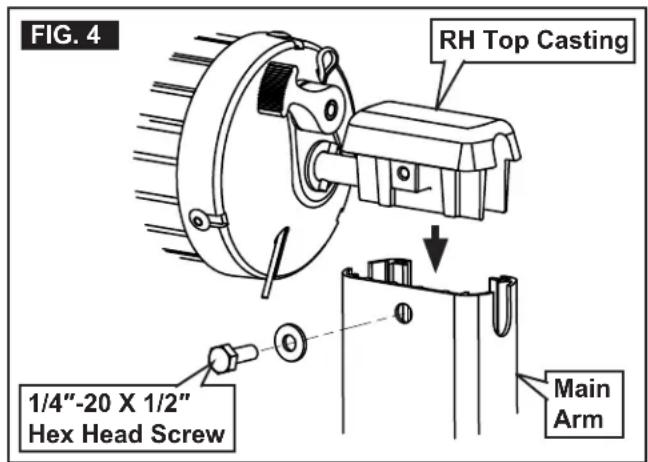
- Insert top casting into corresponding main arm. See (FIG. 4).
PREPARE FOR INSTALLATION
- Place 1/4"-20 X 1/2" hex head screw (with washer) through main arm and into top casting. Tighten to 65-80 in·lb torque. See (FIG. 4).
- Repeat steps (2) and (3) for opposite side.
- Rotate awning safety lock lever to roll down position. See (FIG. 5).

- ⚠WARNING IMPACT OR PINCH HAZARD.
Do NOT remove cotter pin from torsion rod (at end cap) until BOTH top castings are secured to corresponding main arms, and awning safety lock lever is in roll down position. Otherwise, rapid casting spin off will occur. Spring tension will attempt to spin the hardware and/or fabric roller tube quickly and unexpectedly. Failure to obey this warning could result in death or serious injury.
Straighten, remove, and discard cotter pin from left end of torsion rod (LH end cap) only. See (FIG. 6).

D. Determine Awning Location

- WARNING: IMPACT OR CRUSH HAZARD.
Verify mounting surface on RV is flat, has solid structural backing where fasteners penetrate surface, and will safely and securely support product. Otherwise, product may become unstable and could detach, bend, or collapse. Failure to obey this warning could result in death or serious injury.
Find a solid structure in RV wall for support of top mounting brackets.
NOTICE: Do NOT fasten top mounting bracket over awning rail and against rubber cap molding (if RV's roof construction has rounded corners). Otherwise, water leakage could occur.
The relationship between solid structure and awning rail will determine location of top mounting brackets. Possible positions for top mounting brackets include:
- Mounting OVER awning rail. See (FIG. 7).

Do NOT use this position if top mounting brackets will contact rubber cap molding on RV (roof with rounded corners).
- Mounting BELOW awning rail. See (FIG. 8).
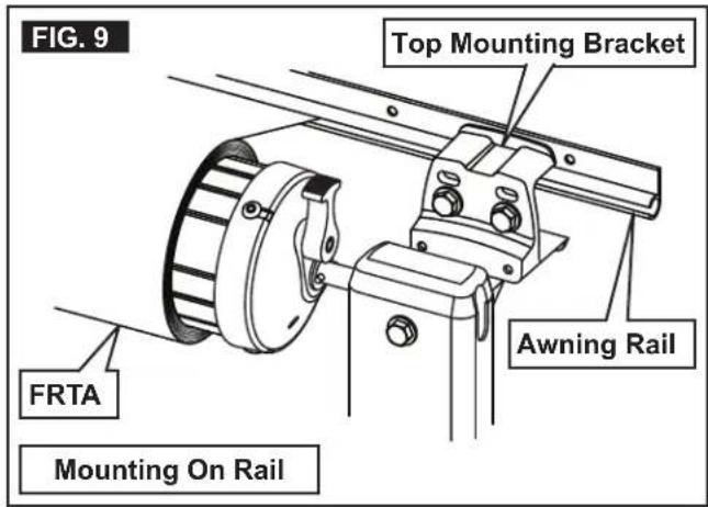
- Mounting ON awning rail. See (FIG. 9).

Install top bracket spacers if awning rail is too wide (has drip channel) and interferes with top mounting brackets. See (FIG. 10).
See subsection, "A. Optional Components" on page (3) to order top bracket spacers.

PREPARE FOR INSTALLATION


- Make sure arm assemblies do not restrict use of doors, windows, etc. See (FIG. 11).

INSTALL AWNING
A. Install LED Light Switch (If Applicable)
An LED light switch (installer supplied) is required for awning models equipped with an LED light strip.
Skip this subsection if awning is NOT equipped with an LED light strip.

- ⚠ WARNING ELECTRICAL SHOCK HAZARD. Disconnect 120 Vac power from RV. Failure to obey this warning could result in death or serious injury.
- NOTICE Disconnect the positive (+) 12 Vdc terminal from supply battery. Otherwise, damage to unit could occur.
- NOTICE Do NOT expose switch to weather, extreme temperatures, or long hours in direct sunlight.
Find a suitable location for LED switch installation.
- NOTICE Install a (3 A) fuse (installer supplied) at fuse panel for positive (+) 12 Vdc power
supply (RED wire) to switch. Otherwise, damage to unit could occur.
Alternatively, a (3 A) inline fuse may be used between positive (+) 12 Vdc power supply (RED wire) and switch.
- Route wiring (inside RV) to general location where connections to awning hardware will be made.
Allow enough wiring length to pass through outside RV wall (hole will be drilled later) for connection to awning. Wiring hole location will be near RH top casting. See (FIG. 4).
- Make appropriate wiring connections inside RV.
Wiring connections to awning (through outside RV wall) will be made later. See instructions included with your LED light switch for additional wiring instructions.
INSTALL AWNING
B. Insert Awning Fabric Into Awning Rail

- With awning safety lock lever in roll down position, unfurl awning fabric 1 revolution.

Unfurling 1 revolution will allow enough space between RV wall and awning hardware to guide fabric as it is inserted into awning rail.
- CAUTION: LIFTING HAZARD. Use proper lifting technique and control when lifting product. Failure to obey this caution could result in injury. With one person grasping each arm assembly, carefully lift entire awning assembly upright. Then carry awning to prepared (flared) awning rail end. See (FIG. 12).

- While one person guides awning fabric into awning rail, carefully move (carry) awning assembly to predetermined location. See (FIG. 12).

To determine correct awning location, see subsection, "D. Determine Awning Location" on page (6).
A stepladder may be necessary to reach awning rail.
At least two other people are required to hold and control awning hardware until:
- both top mounting brackets are correctly installed;
- both bottom mounting brackets are correctly installed;
- both patio feet are securely latched into bottom mounting brackets.
C. Install Top Mounting Brackets

- When the awning is in the predetermined location, extend both adjustable arms down to help support the awning assembly.

To determine the correct awning location, see subsection, “D. Determine Awning Location” on page (6).
a. Pull the lift handle out and CAREFULLY extend the adjustable arm until the patio foot contacts the floor/ground. See (FIG. 13). b. With the FRTA at the same height (approximately) as the awning rail, release the lift handle to lock it in position. See (FIG. 8) & (FIG. 13). c. Repeat steps (a) through (b) for the opposite side.

- Push in one side tab of the arm safety lock, then the other, to disengage the main rafter from the main arm. See (FIG. 14).

INSTALL AWNING
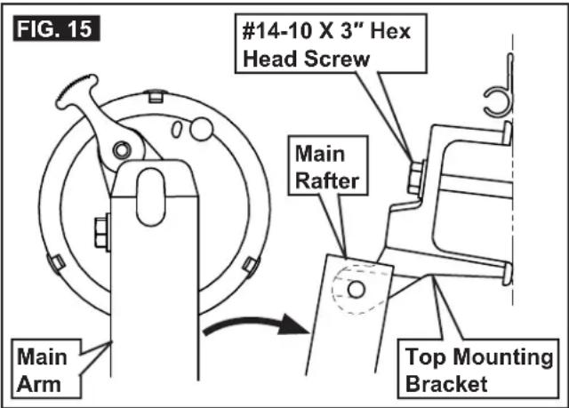
- Make sure the main rafter is aligned directly behind and centered with the main arm. Then carefully pull the main rafter away from the main arm (toward the RV), and mark the hole locations for the top mounting bracket. See (FIG. 7), (FIG. 8), (FIG. 9), & (FIG. 15).
- ⚠️WARNING FIRE OR ELECTRICAL SHOCK HAZARD. Verify there are no obstacles inside the RV's roof and/or walls (wires, pipes, etc.). Shut OFF the gas supply, disconnect 120 Vac power from the RV, and disconnect the positive (+) 12 Vdc terminal from the supply battery BEFORE drilling or cutting into the RV. Failure to obey these warnings could result in death or serious injury.
Drill 3/16" diameter holes through the marked mounting hole locations and into the solid structure of the RV.

Drill 7/32" diameter holes if drilling into steel.
- NOTICE ALWAYS use sealant on (clean) parts and surfaces where fasteners enter the RV's roof and/or walls. Otherwise, water leakage could occur.
Apply sealant to #14-10 X 3" hex head screw threads. Then place and tighten screws through the top mounting bracket and into the solid structure of the RV. See (FIG. 7), (FIG. 8), (FIG. 9), & (FIG. 15).
- Repeat steps (2) through (5) for the opposite side.
- Lift and place the top casting onto the top mounting bracket's top pivot. Then push (squeeze) the main rafter into the main arm until the arm safety lock snaps securely in place. See (FIG. 14) & (FIG. 16).

- Repeat step (7) for the opposite side.
D. Install Bottom Mounting Brackets

- Latch the bottom mounting bracket onto the patio foot (located on the bottom of the adjustable arm). See (FIG. 17).

- Make sure the top casting is still resting on the top pivot of the top mounting bracket. See (FIG. 16).
INSTALL AWNING
3. ⚠ WARNING: IMPACT OR CRUSH HAZARD.
Verify that the mounting surface on the RV is flat, has solid structural backing where fasteners penetrate the surface, and will safely and securely support the product. Otherwise, the product may become unstable and could detach, bend, or collapse. Failure to obey this warning could result in death or serious injury.
Find a solid structure in the RV wall to install the bottom mounting bracket. Then adjust the arm to place the bottom mounting bracket in the desired mounting position. See (FIG. 13), (FIG. 17), and (FIG. 18).

Mount directly into the RV floor line, over molding, etc. If installing over RV molding, a bottom spacer MUST be used.
See subsection "A. Optional Components" on page (3) to order bottom spacer kits.
a. While one person holds and controls the main arm, pull the lift handle out. b. Slide the adjustable arm up or down until the bottom mounting bracket is in the desired mounting position. c. Release the lift handle to lock in position.

The lift handle MUST be locked in position to complete installation (later steps).

- Square the arm assembly to the RV and FRTA. See (FIG. 19).

Measuring from a door or window frame is acceptable.

- While holding the bottom mounting bracket against the RV wall, mark the hole locations. See (FIG. 17) and (FIG. 19).
- ⚠️ WARNING: FIRE OR ELECTRICAL SHOCK HAZARD. Verify there are no obstacles inside the RV's roof and/or walls (wires, pipes, etc.). Shut OFF the gas supply, disconnect 120 Vac power from the RV, and disconnect the positive (+) 12 Vdc terminal from the supply battery BEFORE drilling or cutting into the RV. Failure to obey these warnings could result in death or serious injury.
Drill 3/16" diameter holes through the marked mounting hole locations and into the solid structure of the RV.

Drill 7/32" diameter holes if drilling into steel.
- NOTICE: ALWAYS use sealant on (clean) parts and surfaces where fasteners enter the RV's roof and/or walls. Otherwise, water leakage could occur.
Apply sealant to the #14 hex head screw threads. Then place and tighten screws through the bottom mounting bracket and into the solid structure of the RV.
- Repeat steps (1) through (7) for the opposite side.
E. Install Stop Bolts
NOTICE: Install the shoulder bolt (stop bolt) to help prevent over-travel of the arm assembly.

Before proceeding with stop bolt installation:
- The bottom mounting bracket MUST be installed.
- The patio foot MUST be latched into the bottom mounting bracket.
- The lift handle MUST be locked in position.

- Pull the lift handle out and slide the main arm up by one hole only. Then release the lift handle to lock it in position. See (FIG. 13).
INSTALL AWNING
- Place a 5/16"-18 x 1" shoulder (stop) bolt through the highest fully exposed hole in the adjustable arm (nearest the bottom edge of the main arm). Then secure it with a 5/16"-18 lock nut. See (FIG. 20).
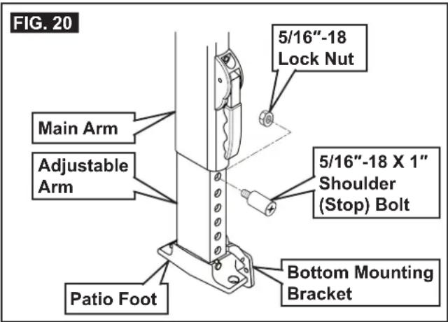
- Pull the lift handle out and slide the main arm down until it rests on the stop bolt. Then release the lift handle to lock it in position. See (FIG. 13) & (FIG. 20).

The top casting should now clear the top pivot by 1/2" when the awning closes. See (FIG. 16).
- Repeat steps (1) through (3) for the opposite side.
F. Release Preset Tension
⚠ WARNING: IMPACT OR PINCH HAZARD. Do NOT remove the cotter pin from the torsion rod (at the end cap) until BOTH top castings are secured to the corresponding main arms, and the awning safety lock lever is in the roll down position. Otherwise, rapid casting spin-off will occur. Spring tension will attempt to close the awning quickly and unexpectedly. Failure to obey this warning could result in death or serious injury. With the awning safety lock lever in the roll down position, straighten, remove, and discard the cotter pin from the right end of the torsion rod (RH end cap). See (FIG. 21).

Removing the cotter pins will release the factory preset tension. To facilitate removal, you may need to twist the fabric roller tube (as if un-rolling the awning) by pulling the bottom of the tube toward you while pulling on the cotter pin.

G. Secure Awning Fabric To Awning Rail

- ⚠ CAUTION: PINCH HAZARD. Maintain a horizontal distance of at least 16" between the fully open awning and any permanent object. Failure to obey this caution could result in injury.
Open and close the awning four or five times to allow for natural self-adjustment of the awning fabric. See Operating Instructions.
- Verify alignment of the awning fabric and awning hardware.
a. If there is misalignment, make adjustments accordingly. b. Cycle the awning again to check alignment.
- Ensure the arm assemblies are still positioned correctly (directly in front of the top brackets), then mark the location of the awning fabric edges on the awning rail.
- Pull one edge of the awning fabric approximately 1/4" beyond the marked position. Then secure it with a #6 X 7/16" TEK screw through the awning rail (approximately 2" from the fabric edge). See (FIG. 22).

INSTALL AWNING
- Pull to stretch opposite edge of awning fabric approximately 3/4". Then secure with #6 X 7/16" TEK screw through awning rail (approximately 2" from fabric edge).
H. LED Light Connections (If Equipped)

Skip this subsection if awning is NOT equipped with an LED light strip.

- WARNING: FIRE OR ELECTRICAL SHOCK HAZARD. Verify there are no obstacles inside RV's roof and/or walls (wires, pipes, etc.). Shut OFF gas supply, disconnect 120 Vac power from RV, and disconnect positive (+) 12 Vdc terminal from supply battery BEFORE drilling or cutting into RV. Failure to obey these warnings could result in death or serious injury.
With awning open, drill (1) 5/8" diameter hole through outside wall of RV (near RH top casting and under awning rail).

Make sure location will allow LED wiring to pass through wall without interference.
- NOTICE: Do NOT pinch wiring or allow wiring to rub against sharp edges. If wiring is damaged, it MUST be replaced by a qualified service technician.
Use a grommet (installer supplied) when routing wiring through RV wall.

If grommet is NOT used, use heat-shrink tubing where wiring will pass through RV wall.
- NOTICE: ALWAYS seal wiring against weather and moisture where wiring enters RV's roof and/or walls. Otherwise, water leakage could occur. Pull wiring through wiring hole (and grommet).

If grommet is NOT used, make sure sealant will also provide effective and permanent protection against wire damage.
- NOTICE: Verify the positive (+) 12 Vdc terminal is disconnected from supply battery. Otherwise, damage to unit could occur.
Connect LED switch wiring to the factory pre-wired LED light strip.

See instructions included with your LED switch kit (installer supplied) for additional wiring instructions.
- Secure wiring to prevent pinching or other damage during awning operation.

Allow enough slack in wiring to safely accommodate possible fabric movement.
VERIFY INSTALLATION
A. Test Operation
Operate awning according to Operating Instructions to verify all parts are functioning correctly.
B. Secure Awning For Travel

- Fully close awning. See "Close Awning" in Operating Instructions.
- Verify awning is secure for travel. See "Prepare Awning For Travel" in Operating Instructions.
C. Keep Literature
Instructions contain valuable information for product use and consumer safety.

Keep BOTH the Installation and Operating Instructions with product.
- INSTALLATION INSTRUCTIONS
- UNIVERSAL SERIES
- PATIO AWNING
- INTRODUCTION
- TABLE OF CONTENTS
- DOCUMENT SYMBOLS
- IMPORTANT SAFETY INSTRUCTIONS
- RECOGNIZE SAFETY INFORMATION
- UNDERSTAND SIGNAL WORDS
- SUPPLEMENTAL DIRECTIVES
- U.S.A
- CANADA
- GENERAL SAFETY MESSAGES
- GENERAL INFORMATION
- OPTIONAL COMPONENTS
- SPECIFICATIONS
- PREPARE FOR INSTALLATION
- DOOR ROLLER AND EDGE GUARD (OPTIONAL)
- PREPARE AWNING RAIL
- PREPARE AWNING FOR INSTALLATION
- DETERMINE AWNING LOCATION
- INSTALL AWNING
- INSTALL LED LIGHT SWITCH (IF APPLICABLE)
- INSERT AWNING FABRIC INTO AWNING RAIL
- INSTALL TOP MOUNTING BRACKETS
- INSTALL BOTTOM MOUNTING BRACKETS
- ⚠ WARNING: IMPACT OR CRUSH HAZARD
- INSTALL STOP BOLTS
- RELEASE PRESET TENSION
- SECURE AWNING FABRIC TO AWNING RAIL
- LED LIGHT CONNECTIONS (IF EQUIPPED)
- VERIFY INSTALLATION
- TEST OPERATION
- SECURE AWNING FOR TRAVEL
- KEEP LITERATURE
Brand : DOMETIC
Model : Window Awning
Category : Window Blinds