
EAP610 V2 - Access Point TP-LINK - Free user manual and instructions
Find the device manual for free EAP610 V2 TP-LINK in PDF.


| Product Type | Wireless Access Point |
| Model | EAP610 V2 |
| Wireless Standard | Wi-Fi 6 (802.11ax) |
| Frequency Bands | 2.4 GHz and 5 GHz |
| Maximum Data Rate | 2.4 GHz: 574 Mbps, 5 GHz: 1.2 Gbps |
| Ethernet Port | 1× Gigabit RJ45 with PoE support |
| Power Supply | PoE (802.3af/at) or 12V DC adapter |
| Dimensions (W×D×H) | 160 × 160 × 35 mm (6.3 × 6.3 × 1.4 in) |
| Weight | 0.31 kg (0.68 lb) |
| Mounting | Ceiling or wall mount (bracket included) |
| Management | Standalone or via Omada Controller (software/hardware) |
| Security Features | WPA3, WPA2-Enterprise, MAC filtering, VLAN, Rogue AP detection |
| LED Indicators | Power, LAN, 2.4G, 5G |
| Operating Temperature | 0°C to 40°C (32°F to 104°F) |
| Humidity | 10% to 90% non-condensing |
| Antenna | Internal antennas (not user-replaceable) |
| Repairability | Limited; no user-serviceable parts; contact support for issues |
| Cleaning Instructions | Wipe with a soft dry cloth; avoid liquids and abrasives |
| Certifications | CE, FCC, RoHS |
Frequently Asked Questions - EAP610 V2 TP-LINK
User questions about EAP610 V2 TP-LINK
0 question about this device. Answer the ones you know or ask your own.
Ask a new question about this device
Download the instructions for your Access Point in PDF format for free! Find your manual EAP610 V2 - TP-LINK and take your electronic device back in hand. On this page are published all the documents necessary for the use of your device. EAP610 V2 by TP-LINK.
USER MANUAL EAP610 V2 TP-LINK
About This User Guide.... 1
Overview 3
1 Quick Start....4
1.1 Determine the Management Method....5 1.2 Connect Network Devices....6 1.3 Log in to the EAP and Change the SSID....8 1.4 Configure and Manage the EAP....21
2 Configure the Network....22
2.1 Configure the Wireless Parameters....23 2.1.1 Configure SSIDs 24 2.1.2 Configure Wireless Advanced Settings 30 Radio Setting....30 Load Balance....32 Airtime Fairness 32 More Settings 33
2.2 Configure Portal Authentication ....35
Configure Portal....36
Configure Free Authentication Policy 42
2.3 Configure VLAN....45
2.4 Configure MAC Filtering....46
2.5 Configure Scheduler....49
2.6 Configure Band Steering....52
2.7 Configure QoS....54
2.8 Configure Rogue AP Detection....58
Detect Rogue APs and Move the Rogue APs to the Trusted AP List.... 59
Manage the Trusted AP List....60
3 Monitor the Network....62
3.1 Monitor the EAP....63 3.2 Monitor the Wireless Parameters....65
Monitor the SSIDs....66 Monitor the Radio Settings....67 Monitor Radio Traffic 67 Monitor LAN Traffic 68
3.3 Monitor the Clients....70
View Client Information....70 View Block Client Information 72
4 Manage the EAP....73
4.1 Manage the IP Address of the EAP....74 4.2 Manage System Logs....77
View System Logs 77 Configure the Way of Receiving Logs....78
4.3 Configure Web Server....80 4.4 Configure Management Access....81
Configure Access MAC Management....81 Configure Management VLAN 82
4.5 Configure LED 83 4.6 Configure Wi-Fi Control (Only for Certain Devices)....84 4.7 Configure PoE Out (Only for Certain Devices) 85 4.8 Configure SSH....86 4.9 Configure SNMP 87
5 Configure the System....89
5.1 Configure the User Account....90 5.2 Controller Settings....91
Enable Cloud-Based Controller Management 91
Configure Controller Inform URL 93
5.3 Configure the System Time....94
Configure the System Time 95
Configure Daylight Saving Time....97
5.4 Reboot and Reset the EAP....99
5.5 Backup and Restore the Configuration....100
5.6 Update the Firmware 101
6 Application Example 102
6.1 Determine the Network Requirements....103
6.2 Build the Network Topology....104
6.3 Log in to the EAP 105
6.4 Configure the EAP 106
Configure SSIDs 106
Configure Portal Authentication....107
Configure Scheduler....109
6.5 Test the Network....111
About This User Guide
When using this guide, notice that features available in the EAP may vary by model and software version. Availability of the EAP may also vary by region or ISP. All images, steps, and descriptions in this guide are only examples and may not reflect your actual experience.
Some models featured in this guide may be unavailable in your country or region. For local sales information, visit https://www.tp-link.com.
The information in this document is subject to change without notice. Every effort has been made in the preparation of this document to ensure the accuracy of the contents, but all statements, information, and recommendations in this document do not constitute the warranty of any kind, express or implied. Users must take full responsibility for their application of any product.
Conventions
Unless otherwise noted, the introduction in this guide takes EAP245 as an example.
Wireless Speed, Range and Connected Devices Disclaimer
Maximum wireless transmission rates are the physical rates derived from IEEE Standard 802.11 specifications. Range and coverage specifications along with the number of connected devices were defined according to test results under normal usage conditions. Actual wireless transmission rate, wireless coverage, and number of connected devices are not guaranteed, and will vary as a result of 1) environmental factors, including building materials, physical objects and obstacles, 2) network conditions, including local interference, volume and density of traffic, product location, network complexity, and network overhead and 3) client limitations, including rated performance, location, connection quality, and client condition.
MU-MIMO Disclaimer (for EAPs that support MU-MIMO)
MU-MIMO capability requires client devices that also support MU-MIMO.
Seamless Roaming Disclaimer (for EAPs that support Seamless Roaming)
Seamless roaming requires both the access point and client devices to support 802.11k and 802.11v protocols.
Lightning and Electro-Static Discharge Protection Disclaimer (for Outdoor EAPs)
Protection against lightning and electro-static discharge may be achieved through proper product setup, grounding and cable shielding. Refer to the instruction manual and consult an IT professional to assist with setting up this product.
More Info
Some models featured in this guide may be unavailable in your country or region. For local sales information, visit https://www.tp-link.com.
For technical support, latest software, and management app, visit https://www.tp-link.com/support.
The Quick Installation Guide can be found where you find this guide or inside the package of the EAP.
The authentication information can be found where you find this guide.
Specifications can be found on the product page at https://www.tp-link.com.
To ask questions, find answers, and communicate with TP-Link users or engineers, please visit https://community.tp-link.com to join TP-Link Community.
If you have any suggestions or needs on the product guides, welcome to email techwriter@tp-link.com.cn.
Overview
Omada series products provide wireless coverage solutions for small-medium business and households. They can either work independently as standalone APs or be centrally managed by Omada Software Controller, Omada Hardware Controller (OC200/OC300), or Omada Cloud-Based Controller, providing a flexible, richly-functional but easily configured wireless network for small-medium business and households.
1 Quick Start
This chapter introduces how to build a wireless network using the EAPs and how to complete the basic settings. Follow the steps below:
1.1 Determine the Management Method 1.2 Connect Network Devices 1.3 Log in to the EAP and Change the SSID 1.4 Configure and Manage the EAP
1.1 Determine the Management Method
Before building your network, choose a proper method to manage your EAPs. You have the following two options:
■ Controller Mode
If you want to manage a large-scale network centrally, choose Controller Mode. In Controller Mode, you can configure and monitor mass EAPs, switches, and gateways via Omada SDN Controller. For detailed instructions, go to the Support Webpage of Omada Controller and download the User Guide.
■ Standalone Mode
If you want to manage only a few EAPs, choose Standalone Mode. In Standalone Mode, you can singly configure and monitor your EAPs via Omada APP or a web browser, and each EAP has its own management page.
This chapter introduces how to start configuring the EAP in Standalone Mode.
Note:
- Standalone Mode is inaccessible while the EAP is managed by a controller. To turn the EAP back to Standalone Mode, you can forget the EAP on the controller or reset the EAP.
- To make your EAPs discovered by the controller, you need to configure 5.2 Controller Settings in certain scenarios.
1.2 Connect Network Devices
To connect your EAPs to the local network, refer to the following topology.
![graph LR A["Internet"] -->|WAN| B["Router (DHCP Server)"] B -->|L| C["AN"] C --> D["EAP"] C --> E["EAP"] D --> F["Mobile Device"] E --> G["Client"]](/content/2026/06/1377910/images/cc432bae910432325d97b0c09b6d5405474f540f1c0ed9e4cb7e0c6b6ea559ec.jpg)
- Connect the WAN port (or Internet port) of the router to the internet.
- Connect your EAPs to the LAN port of the router.
- Connect your wireless clients such as phones, tablets and laptops to the WiFi of the EAP. The default SSID is printed at the bottom of the EAP.
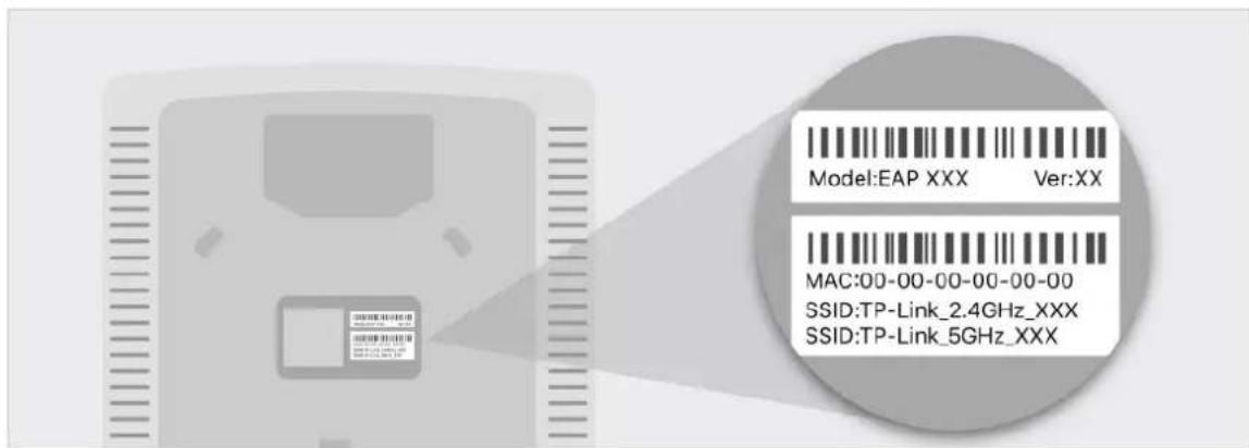
Now you can surf the internet on your phones, tablets and laptops. If you cannot access the internet, follow the FAQ to troubleshoot the problem.
Tips:
- If you want to power your EAPs using a PoE switch, refer to the following topology.
![graph LR A["Internet"] -->|WAN| B["Router (DHCP Server)"] B -->|L| C["An"] C --> D["EAP"] C --> E["EAP"] D --> F["Mobile Device"] E --> G["Client"]](/content/2026/06/1377910/images/06dd54daed6b06cb14336978a08e0bc5e664d4a197e503d007f624997a3bbb14.jpg)
- The router is the gateway of the network, and devices in the LAN access the internet via the router. At the same time, the router acts as a DHCP server to assign dynamic IP addresses to the EAPs and clients.
- The dual-band EAP has two default SSIDs: TP-Link_2.4GHz_XXXXXX on the 2.4GHz band and TP-Link_5GHz_XXXXXX on the 5GHz band. The single-band EAP has a default SSID named TP-Link_2.4GHz_XXXXXX on the 2.4GHz band.
1.3 Log in to the EAP and Change the SSID
By default, anyone can connect to the WiFi of the EAP without authentication because the default SSID has no password. For security purposes, we recommend changing the default SSID.
Log in to the EAP before changing the default SSID. You can use either the Omada App on your mobile device or the web browser on your PC. Choose a method from the following sections and follow the instructions.
Tips:
- Only one user is allowed to log in to the EAP at a time.
- The Omada app is designed to help you quickly configure some basic settings. To configure advanced functions, use the web browser on your PC.
- The Omada app is only compatible with certain firmware versions of the EAP. To check the firmware versions of the supported EAPs, please refer to https://www.tp-link.com/omada_compatibility_list.
■ Using Omada App on Your Mobile Device![graph LR A["Internet"] --> B["WAN"] B --> C["Router (DHCP Server)"] C --> D["AN"] D --> E["EAP"] D --> F["EAP"] E --> G["Mobile Device Installed with Omada App"] F --> G](/content/2026/06/1377910/images/12610f3380029ac35366f78aec1f62b1a319d162c3f2ecd0ce5f5baf743fc003.jpg)
- To install the Omada App, launch the Apple App Store (iOS) or Google Play Store (Android) and search "TP-Link Omada" or simply scan the QR code to download and install the app.

Scan for Omada App Download Omada App
- Connect your mobile device to the WiFi of the EAP. The default SSID is printed at the bottom of the EAP.

- Launch the Omada app, tap Standalone APs and wait for the EAP to be discovered.
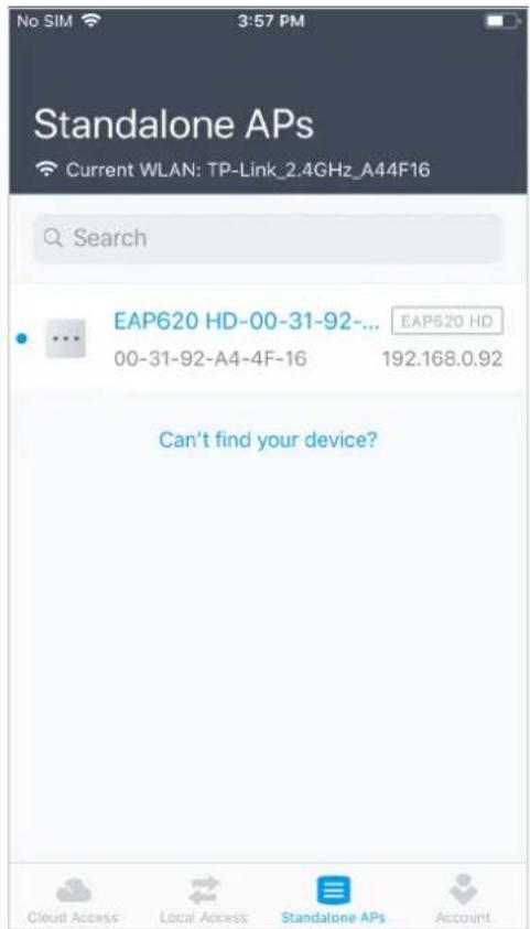
Tips:
All the EAPs in the same subnet will be discovered by Omada app and shown on the page.
- Tap on the EAP appearing on the page. Set a new username and password for your login account of the EAP.

- Change the SSID and password to keep your wireless network secure. Tap Next.
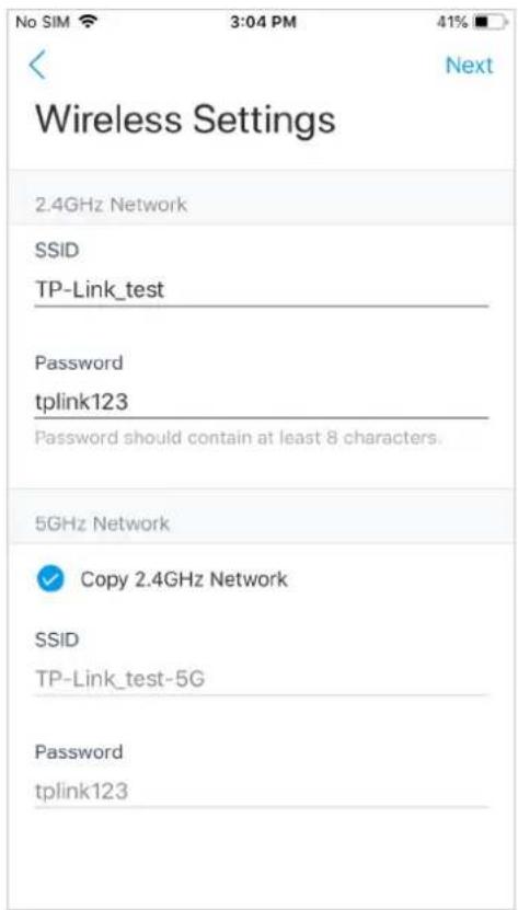
- Confirm the settings in the summary page. Tap Next, and the settings will take effect in several minutes.

- To join your new wireless network, select the SSID and tap Join.

- Tap Continue to go to the management page. In this page, you can view the information and settings of the EAP. If you want to change the settings including radio, SSID and device account, tap ☐.

Now you can connect your phones, tablets and laptops to the new WiFi. If you cannot access the internet, follow the FAQ to troubleshoot the problem.
■ Using Web Browser on Your PC and Connecting to the WiFi![graph LR A["Internet"] -->|WAN| B["Router (DHCP Server)"] B -->|L| C["AN"] C --> D["EAP"] C --> E["EAP"] D --> F["PC"] E --> F style A fill:#f9f,stroke:#333 style B fill:#ccf,stroke:#333 style C fill:#cfc,stroke:#333 style D fill:#fcc,stroke:#333 style E fill:#fcc,stroke:#333 style F fill:#cff,strok…](/content/2026/06/1377910/images/0cebc9526bcf37e4403fd6ec10ae23b8de8092f7209720a103049999b2c8bd07.jpg)
- Set your PC to obtain an IP address automatically.

- Connect your PC to the WiFi of the EAP. The default SSID is printed at the bottom of the EAP.

- Make sure that your PC has got the IP address, default gateway, and DNS server from the DHCP server.

- To log in to the EAP, launch a web browser and enter http://tplinkeap.net in the address bar. The login page will appear. By default, both the username and password are admin.

- After logging in to the EAP, follow the step-by-step instructions to complete the basic configurations. In the pop-up window, configure a new username and a new password for your user account, then click Next.

tp-link
Set up a new account
New Username:
New Password:
Confirm Password:
user1
●●●●●●●●
LOW
Module
- 田内田
• • • • • • • •

Next
- Configure the SSID and password. For the dual-band EAP, you can configure the SSID and password for both 2.4GHz and 5GHz. Click Save.

tp-link
Wireless Basic Settings
2.4GHz Wireless Radio:
SSID:
Password:

Enable
SSID-1
12345678
5GHz Wireless Radio:
SSID:
Password:

Enable
SSID-2
12345678
Back
Save
Skip
Tips:
You can skip this step and configure wireless settings later on the management page. If needed, you can also create more SSIDs. For detailed instructions, refer to 2.1 Configure the Wireless Parameters.
- The following page will appear. Make sure that your device has connected to the new wireless network and tick the checkbox. Then click Finish.

Now you can connect your phones, tablets and laptops to the new WiFi. If you cannot access the internet, follow the FAQ to troubleshoot the problem.
■ Using Web Browser on Your PC and Connecting to the Ethernet
- Get the IP address of the EAP. There are two methods.
• Using DHCP Client List of the Router
Log in to the router which acts as the DHCP server. In the DHCP client list, find the IP address of your EAP according to its MAC address. The MAC address can be found at
the bottom of the EAP. In the following figure, for example, the IP address of the EAP is 192.168.0.118.

Tips:
When the DHCP server is not available in your network, the EAP has the DHCP fallback IP address, which is 192.168.0.254 by default.
• Using EAP Discovery Utility
Go to https://www.tp-link.com/download/EAP-Controller.html#EAP_Discovery_Tool to download, install and launch EAP Discovery Utility on your PC. EAP Discovery Utility can
scan all EAPs in the same network segment, and find the IP address of the EAP. In the following figure, for example, the IP address of the EAP is 192.168.0.5.

Tips:
Some EAP models only work with certain software versions of Discovery Utility. If your Discovery Utility can't discover your EAP anyway, try a different software version.
- To log in to the EAP, launch a web browser and enter the IP address of the EAP in the address bar. The login page will appear. By default, both the username and password are admin.
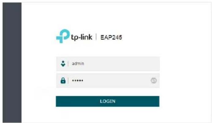
Tips:
To facilitate access to the EAP, you can set a static IP address for the EAP and remember it well or write it down. But make sure that this IP address is not being used by other devices in the same LAN. For detailed instructions about how to set a static IP address for the EAP, refer to 4.1 Manage the IP Address of the EAP.
- After logging in to the EAP, follow the step-by-step instructions to complete the basic configurations. In the pop-up window, configure a new username and a new password for your user account, then click Next.

tp-link
Set up a new account
New Username:
New Password:
Confirm Password:
user1
●●●●●●●●
LOW
Module

Next
- Configure the SSID and password. For the dual-band EAP, you can configure the SSID and password for both 2.4GHz and 5GHz. Click Save.

tp-link
Wireless Basic Settings
2.4GHz Wireless Radio:
SSID:
Password:

Enable
SSID·1
12345678
5GHz Wireless Radio:
SSID:
Password:

Enable
SSID-2
12345678
Back
Save
Skip
Tips:
You can skip this step and configure wireless settings later on the management page. If needed, you can also create more SSIDs. For detailed instructions, refer to 2.1 Configure the Wireless Parameters
- The following page will appear. Make sure that your device has connected to the new wireless network and tick the checkbox. Then click Finish.

tp-link
Success!
Connect to your device and continue the configuration
2.4GHz Wireless
SSID: SSID-1
Password: 12345678
5GHz Wireless
SSID: SSID-2
Password: 12345678

I have connected to the new wireless network.
Finish
Now you can connect your phones, tablets and laptops to the new WiFi. If you cannot access the internet, follow the FAQ to troubleshoot the problem.
1.4 Configure and Manage the EAP
If you use the web browser to configure your EAP, you can configure more advanced functions according to your needs, and manage it conveniently on the web page.
On the top of the page, you can click to log out and click to open the technical support website.
There are four tabs: Status, Wireless, Management and System. The following table introduces what you can configure under each tab, and the following chapters discuss these topics in detail.
Status You can view the information of the EAP, wireless traffic and clients.
Wireless You can configure the wireless parameters and advanced features, such as Portal, VLAN, MAC Filtering, Scheduler, Band Steering, QoS and Rogue AP Detection.
Management You can manage the EAP using the management features, such as System Logs, Web Server, Management Access, LED Control, SSH and SNMP.
System You can configure the system parameters, including the login account and the system time. In addition, you can reboot and reset the EAP, backup and restore the configuration, and upgrade the EAP using the new firmware file.
2 Configure the Network
This chapter introduces how to configure the network parameters and the advanced features of the EAP, including:
• 2.1 Configure the Wireless Parameters • 2.2 Configure Portal Authentication • 2.3 Configure VLAN • 2.4 Configure MAC Filtering • 2.5 Configure Scheduler • 2.6 Configure Band Steering • 2.7 Configure QoS • 2.8 Configure Rogue AP Detection
2.1 Configure the Wireless Parameters
To configure the wireless parameters, go to the Wireless > Wireless Settings page.

For a dual-band EAP, there are two bands: 2.4GHz and 5GHz. The wireless parameters are separately set on each band. You can click 2.4GHz to select a band and configure the wireless parameters on this band.
Before configuring the wireless parameters on each band, check the box to enable 2.4GHz or 5GHz Wireless Radio. Only when this option is enabled will the wireless radio on 2.4GHz or 5GHz band work.
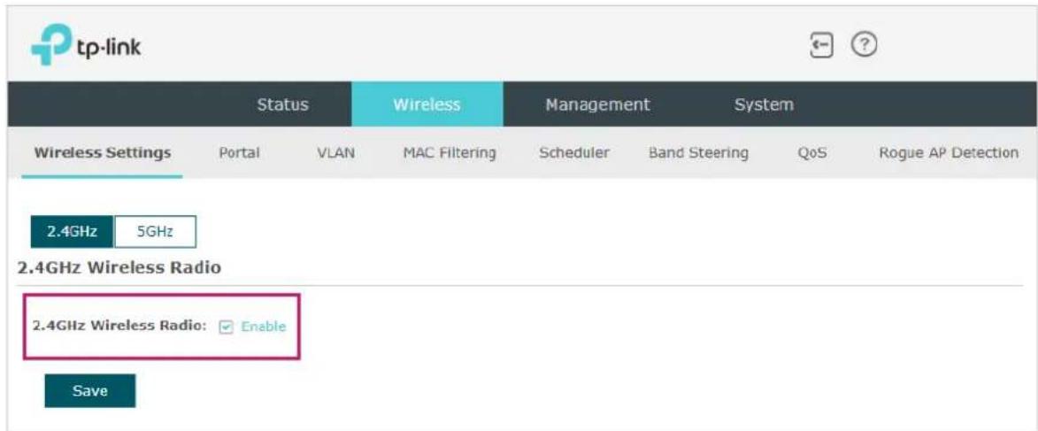
Demonstrated with 2.4GHz, the following sections introduce these contents: 2.1.1 Configure SSIDs and 2.1.2 Configure Wireless Advanced Settings.
2.1.1 Configure SSIDs
SSID (Service Set Identifier) is used as an identifier for a wireless LAN, and is commonly called the "network name". Clients can find and access the wireless network through the SSID. For one EAP, you can build up to eight SSIDs per frequency band.

Follow the steps below to create an SSID on the EAP:
- If your EAP is a dual-band device, click which the new SSID will be created.

to choose a frequency band on
- Click + Add to add a new SSID on the chosen band.
Tips:
You can also click 📋 to edit the specific SSID which already exists in the list. And you can click to delete the SSID in the list.

- Configure the following required parameters for this SSID:
SSID Specify a name for the wireless network.
SSID Broadcast With the option enabled, EAP will broadcast the SSID to the nearby hosts, so that those hosts can find the wireless network identified by this SSID. If this option is disabled, users must enter the SSID manually to connect to the EAP.
Security Mode Select the security mode of the wireless network. There are four options:
None: Clients can access the wireless network without authentication.
WEPI WPA-Enterprise / WPA-Personal: Clients need to pass the authentication before accessing the wireless network. For network security, we recommend that you encrypt your wireless network. The following sections will introduce how to configure these security modes.
Guest Network With this option enabled, guest network will block clients from reaching any private IP subnet.
Rate Limit With this option enabled, the download and upload rate of each client which connects to the SSID will be limited to balance bandwidth usage.
You can limit the download and upload rate for some specific clients by configuring rate limit in client list, refer to View Client Information to get more details.
Note that the download and upload rate will be limited to the smaller value if you set the limit value both in SSID and client configuration.
- Click OK to create the SSID.
Following is the detailed instructions about how to configure WEP, WPA-Enterprise and WPA-Personal.
• WEP
WEP (Wired Equivalent Privacy) is a traditional encryption method. It has been proved that WEP has security flaws and can easily be cracked, so WEP cannot provide effective
protection for wireless networks. Since WPA-Personal and WPA-Enterprise are much safer than WEP, we recommend that you choose WPA-Personal or WPA-Enterprise if your clients also support them.
Note:
WEP is not supported in 802.11n mode or 802.11ac mode. If WEP is applied in 802.11n, 802.11ac, or 802.11n/ac mixed mode, clients may not be able to access the wireless network. If WEP is applied in 802.11b/g/n mode (2.4GHz) or 802.11a/n (5GHz), the EAP may work at a low transmission rate.

The following table details how to configure each item:
Type: Select the authentication type for WEP.
Auto: The EAP can select Open System or Shared Key automatically based on the wireless capability and request of the clients.
Open System: Clients can pass the authentication and associate with the wireless network without a password. However, a correct password is necessary for data transmission.
Shared Key: Clients have to input the correct password to pass the authentication; otherwise, they cannot associate with the wireless network or transmit data.
Key Selected: Select one key to specify. You can configure up to four keys.
WEP Key Format: Select ASCII or Hexadecimal as the WEP key format.
ASCII: With this format selected, the WEP key can be any combination of keyboard characters of the specified length.
Hexadecimal: With this format selected, the WEP key can be any combination of hexadecimal digits (0-9, a-f, A-F) with the specified length.
Key Type: Select the WEP key length for encryption.
64-bit: Enter 10 hexadecimal digits or 5 ASCII characters.
128-bit: Enter 26 hexadecimal digits or 13 ASCII characters.
152-bit: Enter 32 hexadecimal digits or 16 ASCII characters.
Key Value: Enter the WEP keys. The length and valid characters are determined by the key format and key type.
- WPA-Enterprise
WPA-Enterprise (Wi-Fi Protected Access-Enterprise) is a safer encryption method compared with WEP and WPA-Personal. It requires a RADIUS server to authenticate the clients via 802.1X and EAP (Extensible Authentication Protocol). WPA-Enterprise can generate different passwords for different clients, which ensures higher network security. But it also costs more to maintain the network, so it is more suitable for business networks.
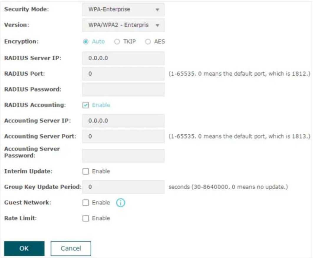
The following table introduces how to configure each item:
Version: Select the version of WPA-Enterprise according to your needs. If you select WPA/WPA2-Enterprise, the EAP automatically decides whether to use WPA-Enterprise or WPA2-Enterprise during the authentication process.
| Encryption Select the Encryption type. Note that some encryption type is only available under certain circumstances. | |
| Auto: The default setting is Auto and the EAP will select TKIP or AES automatically based on the client device's request. | |
| TKIP: Temporal Key Integrity Protocol. TKIP is not supported in 802.11n mode, 802.11ac mode or 802.11n/ac mixed mode. If TKIP is applied in 802.11n, 802.11 ac or 802.11n/ac mixed mode, the clients may not be able to access the wireless network. If TKIP is applied in 11b/g/n mode (2.4GHz) or 11a/n mode(5GHz), the device may work at a low transmission rate. | |
| AES: Advanced Encryption Standard. It is securer than TKIP. | |
| RADIUS Server IP Enter the IP address of the RADIUS Server. | |
| RADIUS Port Enter the port number of the RADIUS Server. | |
| RADIUS Password Enter the shared secret key of the RADIUS server. | |
| RADIUS Accounting Enable or disable RADIUS accounting feature. | |
| Accounting Server IP | Enter the IP address of the accounting server. |
| Accounting Server Port | Enter the port number of the accounting server. |
| Accounting Server Password | Enter the shared secret key of the accounting server. |
| Interim Update With this option enabled, you can specify the duration between accounting information updates. By default, the function is disabled.Enter the appropriate duration between updates for EAPs in Interim Update Interval. | |
| Interim Update Interval | With Interim Update enabled, specify the appropriate duration between updates for EAPs. The default duration is 600 seconds. |
| Group Key Update Period | Specify an update period of the encryption key. The update period instructs how often the EAP should change the encryption key. 0 means that the encryption key does not change at anytime. |
- WPA-Personal
WPA-Personal is based on a pre-shared key. It is characterized by high safety and simple settings, so it is mostly used by common households and small businesses.

The following table introduces how to configure each item:
| Version Select the version of WPA-Personal according to your needs. If you select WPA/WPA2-PSK, the EAP automatically decides whether to use WPA-PSK or WPA2-PSK during the authentication process. | |
| Encryption Select the Encryption type. Note that some encryption type is only available under certain circumstances. | |
| Auto: The default setting is Auto and the EAP will select TKIP or AES automatically based on the client device's request. | |
| TKIP: Temporal Key Integrity Protocol. TKIP is not supported in 802.11n mode, 802.11ac mode or 802.11n/ac mixed mode. If TKIP is applied in 802.11n, 802.11 ac or 802.11n/ac mixed mode, the clients may not be able to access the wireless network. If TKIP is applied in 11b/g/n mode (2.4GHz) or 11a/n mode(5GHz), the device may work at a low transmission rate. | |
| AES: Advanced Encryption Standard. It is securer than TKIP. | |
| Wireless Password | Configure the wireless password with ASCII characters. |
| • For ASCII, the length should be between 8 and 63 and the valid characters contain numbers, letters (case-sensitive) and common punctuations. | |
| Group Key Update Period | Specify an update period of the encryption key. The update period instructs how often the EAP should change the encryption key. 0 means that the encryption key does not change at anytime. |
2.1.2 Configure Wireless Advanced Settings
Proper wireless parameters can improve the performance of your wireless network. This section introduces how to configure the advanced wireless parameters of the EAP, including Radio Setting, Load Balance, Airtime Fairness and More Settings.
Radio Setting
Radio settings directly control the behavior of the radio in the EAP and its interaction with the physical medium; that is, how and what type of signal the EAP emits.
2.4GHz Wireless Advanced Settings
Radio Settings
Load Balance | Airtime Fairness | More Settings
Wireless Mode:
802.11b/g/n mixed
Channel Width:
20/40MHz
Channel:
Auto
Tx Power(EIRP):
20
dBm(6-20)
Note:
The EIRP transmit power includes the antenna gain.
Save
Wireless Mode Select the IEEE 802.11 mode the radio uses.
- For 2.4GHz:
802.11b/g/n/ax mixed: All of 802.11b, 802.11g, 802.11n, and 802.11ax clients operating in the 2.4GHz frequency can connect to the EAP. Note that 802.11ax is only available for certain devices.
802.11b/g/n mixed: All of 802.11b, 802.11g, and 802.11n clients operating in the 2.4GHz frequency can connect to the EAP.
802.11b/g mixed: Both 802.11b and 802.11g clients can connect to the EAP.
802.11n only: Only 802.11n clients can connect to the EAP.
- For 5GHz:
802.11a/n/ac/ax mixed: All of 802.11a, 802.11n, 802.11ac, and 802.11ax clients operating in the 5GHz frequency can connect to the EAP. Note that 802.11ax is only available for certain devices.
802.11a/n/ac mixed: All of 802.11a, 802.11n, and 802.11ac clients operating in the 5GHz frequency can connect to the EAP.
802.11n/ac mixed: Both 802.11n clients and 802.11ac clients operating in the 5GHz frequency can connect to the EAP.
802.11ac only: Only 802.11ac clients can connect to the EAP.
Channel Width Select the channel width of the EAP. The available options differ among different EAPs.
For some EAPs, available options include 20MHz, 40MHz and Auto.
For some EAPs, available options include 20MHz, 40MHz, 80MHz and Auto.
For other EAPs, available options include 20MHz, 40MHz, 80MHz, 160MHz and Auto.
When the radio mode includes 802.11n, we recommend you set the channel bandwidth to 20/40 MHz or 20/40/80MHz to improve the transmission speed. However, you may choose a lower bandwidth due to the following reasons:
- To increase the available number of channels within the limited total bandwidth.
- To avoid interference from overlapping channels occupied by other devices in the environment.
- Lower bandwidth can concentrate higher transmit power, increasing stability of wireless links over long distances.
Channel Limit: Check the box to enable the Channel Limit function. With this function enabled, the wireless frequency 5150MHz~5350MHz will be disabled. This function can influence the available options in Channel. This feature is only available on certain devices. To check whether your device supports this feature, refer to the actual web interface.
Channel: Select the channel used by the EAP. For example, 1/2412MHz means that the channel is 1 and the frequency is 2412MHz.
By default, the channel is automatically selected, and we recommend that you keep the default setting.
Tx Power (EIRP): Specify the transmit power value.
If this value is set to be larger than the maximum transmit power that is allowed by the local regulation, the regulated maximum transmit power will be applied in the actual situation.
Note: In most cases, it is unnecessary to use the maximum transmit power. Specifying a larger transmit power than needed may cause interference to the neighborhood. Also it consumes more power and reduces longevity of the device.
Load Balance
With the Load Balance feature, you can limit the maximum number of clients who can access the EAP. In this way, you can achieve rational use of network resources.
2.4GHz Wireless Advanced Settings
Radio Settings
Load Balance
Airtime Fairness
More Settings
Load Balance:
Maximum Associated Clients:
Enable
(1-99)
Save
Follow the steps below to configure Load Balance:
- Click 2.4GHz or 5GHz to choose a frequency band on which the load balance feature will take effect.
- Check the box to enable Load Balance.
- Specify the maximum number of clients who can connect to the EAP at the same time. While the number of connected clients has reached the limit and there are more clients requesting to access the network, the EAP will disconnect those with weaker signals.
- Click Save.
Airtime Fairness
Note:
Airtime Fairness is only available on certain devices. To check whether your device supports this feature, refer to the actual web interface.
With Airtime Fairness enabled, each client connected to the EAP can get the same amount of time to transmit data, avoiding low-data-rate clients to occupy too much network bandwidth.
Compared with the relatively new client devices, some legacy client devices support slower wireless rate. If they communicate with the same EAP, the slower clients take more time to transmit and receive data compared with the faster clients. As a result, the overall wireless throughput of the network decreases.
Therefore we recommend you check the box to enable this function under multi-rate wireless networks. In this way, the faster clients can get more time for the data transmission and the network overall throughput can be improved.
2.4GHz Wireless Advanced Settings
Radio Settings
Load Balance

| More Settings
Airtime Fairness:
Enable
Save
Note:
With Airtime Fairness enabled, at most 50 wireless clients can connect to the EAP in the 2.4GHz band.
More Settings
Proper wireless parameters can improve the network's stability, reliability, and communication efficiency. The advanced wireless parameters include Beacon Interval, DTIM Period, RTS Threshold, Fragmentation Threshold, and OFDMA.
2.4GHz Wireless Advanced Settings
The following table explains how to configure each item:
| Beacon Interval | Beacons are transmitted periodically by the EAP to announce the presence of a wireless network for the clients. Beacon Interval determines the time interval of the beacons sent by the EAP.You can specify a value between 40 and 100ms. The default is 100ms. |
| DTIM Period The DTIM (Delivery Traffic Indication Message) is contained in some Beacon frames. It indicates whether the EAP has buffered data for client devices. The DTIM Period indicates how often the clients served by this EAP should check for buffered data still on the EAP awaiting pickup.You can specify the value between 1-255 Beacon Intervals. The default value is 1, indicating that clients check for buffered data at every beacon. An excessive DTIM interval may reduce the performance of multicast applications, so we recommend you keep the default value. | |
| RTS Threshold RTS/CTS (Request to Send/Clear to Send) is used to improve the data transmission efficiency of the network with hidden nodes, especially when there are lots of large packets to be transmitted.When the size of a data packet is larger than the RTS Threshold, the RTS/CTS mechanism will be activated. With this mechanism activated, before sending a data packet, the client will send an RTS packet to the EAP to request data transmitting. And then the EAP will send CTS packet to inform other clients to delay their data transmitting. In this way, packet collisions can be avoided.For a busy network with hidden nodes, a low threshold value will help reduce interference and packet collisions. But for a not-so-busy network, a too low threshold value will cause bandwidth wasting and reduce the data throughput. The recommended and default value is 2347 bytes. | |
| Fragmentation Threshold | The fragmentation function can limit the size of packets transmitted over the network. If the size of a packet exceeds the Fragmentation Threshold, the fragmentation function is activated and the packet will be fragmented into several packets.Fragmentation helps improve network performance if properly configured. However, a too low fragmentation threshold may result in poor wireless performance caused by the extra work of dividing up and reassembling of frames and increased message traffic. The recommended and default value is 2346 bytes. |
| OFDMA OFDMA enables multiple users to transmit data simultaneously, and thus greatly improves speed and efficiency. Only when your clients also support OFDMA, can you fully enjoy the benefits.This feature is only available on certain devices. To check whether your device supports this feature, refer to the actual web interface. | |
2.2 Configure Portal Authentication
Portal authentication provides authentication service to clients that only need temporary access to the wireless network, such as customers in a restaurant or supermarket. To access the network, these clients need to enter the authentication login page and use the correct login information to pass authentication. In addition, you can customize the authentication login page and specify a URL to which authenticated clients will be redirected.
In this module, you can also configure Free Authentication Policy, which allows specific clients to access specific network resources without authentication.
To configure portal authentication, go to the Wireless > Portal page.
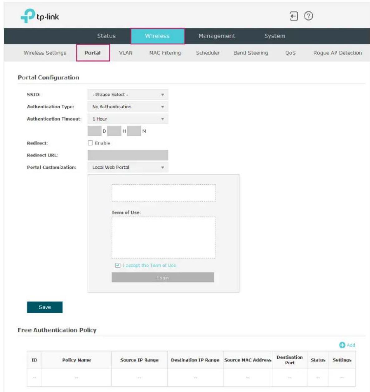
Configure Portal
Three portal authentication types are available: No Authentication, Local Password and External RADIUS Server. The following sections introduce how to configure each authentication type.
- No Authentication
With this authentication type configured, clients can pass the authentication and access the network without providing any login information. They only need to accept the term of use on the authentication page.
Portal Configuration
Follow the steps below to configure No Authentication as the portal authentication type:
- Select the SSID on which the portal will take effect.
- Select No Authentication as the authentication type.
- Configure the relevant parameters as the following table shows:
| AuthenticationTimeout | Specify the value of authentication timeout.A client's authentication will expire after the authentication timeout and the client needs to log in to the authentication page again to access the network.Options include 1 Hour, 8 Hours, 24 Hours, 7 Days, and Custom. With Custom selected, you can customize the time in days, hours, and minutes. |
| Redirect | With this function configured, the newly authenticated client will be redirected to the specific URL. |
| Redirect URL | With Redirect enabled, you also need to enter the URL in this field. The newly authenticated client will be redirected to this URL. |
| PortalCustomization | Configure the authentication page. Local Web Portal is the only available option in this authentication type. Enter the title and term of use in the two boxes.The EAP uses its built-in web server to provide this authentication page for clients. To pass the authentication, clients only need to check the box of I accept the Term of Use and click the Login button. |
- Click Save.
- Local Password
With this authentication type configured, clients are required to provide the correct password to pass the authentication.
Portal Configuration
Follow the steps below to configure Local Password as the portal authentication type:
- Select the SSID on which the portal will take effect.
- Select Local Password as the authentication type.
- Configure the relevant parameters as shown in the following table:
Password: Specify a password for authentication.
| AuthenticationTimeout | Specify the value of authentication timeout.A client's authentication will expire after the authentication timeout and the client needs to log in to the authentication page again to access the network.Options include 1 Hour, 8 Hours, 24 Hours, 7 Days, and Custom. With Custom selected, you can customize the time in days, hours, and minutes. |
| Redirect | With this function configured, the newly authenticated client will be redirected to the specific URL. |
| Redirect URL | With Redirect enabled, you also need to enter the URL in this field. The newly authenticated client will be redirected to this URL. |
| PortalCustomization | Configure the authentication page. Local Web Portal is the only available option is this authentication type. Enter the title and term of use in the two boxes.The EAP uses its built-in web server to provide this authentication page for clients. To pass the authentication, clients need to provide the correct password in the Password field, check the box of I accept the Term of Use and click the Login button. |
- Click Save.
• External RADIUS Server
If you have a RADIUS server on the network to authenticate clients, you can select External RADIUS Server. Clients need to provide the correct login information to pass authentication.
Portal Configuration
RADIUS Accounting: ☑ Enable Accounting Server IP: Accounting Server Port: Accounting Server Password: Interim Update: □ Enable Interim Interval: 600 seconds (60-86400) Authentication Timeout: 1 Hour
Redirect: □ Enable Redirect URL: Portal Customization: Local Web Portal

Save
Follow the steps below to configure External RADIUS Server as the portal authentication type:
- Select the SSID on which the portal will take effect.
- Build a RADIUS server on the network and make sure that it is reachable by the EAP.
- Go to the Portal configuration page on the EAP. Select External RADIUS Server as the authentication type.
- Configure the relevant parameters as shown in the following table:
RADIUS Server IP: Enter the IP address of the RADIUS server.
RADIUS Port: Enter the port of the RADIUS server.
RADIUS Password: Enter the password of the RADIUS server.
NAS ID: Configure a Network Access Server Identifier (NAS ID) using 1 to 64 characters on the portal. The NAS ID is sent to the RADIUS server by the EAP through an authentication request packet. With the NAS ID, which classifies users into different groups, the RADIUS server can send a customized authentication response.
RADIUS Accounting: Enable or disable the RADIUS accounting feature.
Accounting Server IP: Enter the IP address of the accounting server.
Accounting Server Port: Enter the port number of the accounting server.
Accounting Server Password: Enter the shared secret key of the accounting server.
Interim Update: With this option enabled, you can specify the duration between accounting information updates. By default, this function is disabled.
Enter the appropriate duration between updates for EAPs in the Interim Update Interval.
Interim Interval: With Interim Update enabled, specify the appropriate duration between updates for EAPs. The default duration is 600 seconds.
Authentication Timeout: Specify the value of the authentication timeout.
A client's authentication will expire after the authentication timeout, and the client needs to log in to the authentication page again to access the network.
Options include 1 Hour, 8 Hours, 24 Hours, 7 Days, and Custom. With Custom selected, you can customize the time in days, hours, and minutes.
| Redirect With this function configured, the newly authenticated client will be redirected to the specific URL. | |
| Redirect URL | With Redirect enabled, you also need to enter the URL in this field. The newly authenticated client will be redirected to this URL. |
| Portal Customization | Configure the authentication page. There are two options: Local Web Portal and External Web PortalLocal Web PortalEnter the title and term of use in the two boxes. The EAP uses its built-in web server to provide this authentication page for clients. To pass the authentication, clients need to provide the correct username and password in the Username and Password fields, check the box of I accept the Term of Use and click the Login button.External Web PortalWith External Web Portal configured, the authentication page will be provided by the web portal server built on the network. To configure External Web Portal, you need to complete the following configurations:Build an external web portal server on your network and make sure that it is reachable by the EAP.On this configuration page, enter the URL of the authentication page provided by the external portal server. |
| Portal Customization: External Web PortalExternal Web Portal URL: | |
| 3. Add the external web portal server to the Free Authentication Policy list. In this way, clients can access the web portal server before authenticated. For details about how to configure Free Authentication Policy, refer to Configure Free Authentication Policy. | |
4. Click Save.
Configure Free Authentication Policy
Free Authentication Policy allows some specific clients to access the specific network resources without authentication. For example, you can set a free authentication policy to allow clients to visit the external web portal server before authenticated. In this way,
the clients can visit the login page provided by the web portal server and then pass the subsequent authentication process.
Free Authentication Policy
| ID | Policy Name | Source IP Range | Destination IP Range | Source MAC Address | Destination Port | Status | Settings |
| -- | -- | -- | -- | -- | -- | -- | -- |
Follow the steps below to add free authentication policy.
- In the Free Authentication Policy section, click + Add to load the following page.
| ID | Policy Name | Source IP Range | Destination IP Range | Source MAC Address | Destination Port | Status | Settings |
| -- | -- | -- | -- | -- | -- | -- | -- |
 | |||||||
 | |||||||
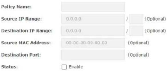
- Configure the following parameters. When all the configured conditions are met, the client can access the network without authentication.
| Policy Name Specify a name for the policy. | |
| Source IP Range Specify an IP range with the subnet and mask length. The clients in this IP range can access the network without authentication.Leaving the field empty means that clients with any IP address can access the specific resources. | |
| Destination IP Range | Specify an IP range with the subnet and mask length. The devices in this IP range can be accessed by the clients without authentication.Leaving the field empty means that all devices in the LAN can be accessed by the specific clients. |
| Source MAC Address | Specify the MAC address of the client, who can access the specific resources without authentication.Leaving the field empty means that clients with any MAC address can access the specific resources. |
Destination Port Specify the port number of the service. When using this service, the clients can access the specific resources without authentication.
Leaving the field empty means that clients can access the specific resources no matter what service they are using.
Status Check the box to enable the policy.
Tips:
When External Web Portal is configured in the portal configuration, you should set the IP address and subnet mask of the external web server as the Destination IP Range. As for Source IP Range, Source MAC Address and Destination Port, you can simply keep them as empty or configure them according to your actual needs.
- Click OK to add the policy.
2.3 Configure VLAN
Wireless VLAN is used to set VLANs for the wireless networks. With this feature, the EAP can work together with the switches supporting 802.1Q VLAN. Traffic from the clients in different wireless networks is added with different VLAN tags according to the VLAN settings of the wireless networks. Then the wireless clients in different VLANs cannot directly communicate with each other. Note that the traffic from the wired clients will not be added with VLAN tags.
To configure VLAN for the wireless network, go to the Wireless > VLAN page.
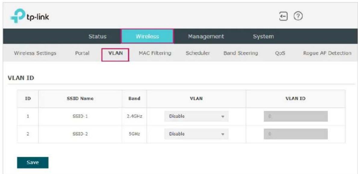
Follow the steps below to configure VLAN on this page.
- Select the specific SSID in the list to configure the VLAN.
- In the VLAN column and select Enable to enable the VLAN function on the SSID.
- Specify the VLAN ID for the wireless network in the VLAN ID column. Every VLAN ID represents a different VLAN. It supports maximum 8 VLANs per frequency band. The VLAN ID range is 0 to 4094. 0 is used to disable VLAN tagging.
- Click Save.
2.4 Configure MAC Filtering
MAC Filtering is used to allow or block the clients with specific MAC addresses to access the network. With this feature you can effectively control clients' access to the wireless network according to your needs.
To configure MAC Filtering, go to the Wireless > MAC Filtering page.

Follow the steps below to configure MAC Filtering on this page:
- In the Settings section, check the box to enable MAC Filtering, and click Save.
Settings
Enable MAC Filtering

- In the Station MAC Group section, click + Create Groups and the following page will appear.
Station MAC Group
| MAC Group Name | Modify | ID | MAC Address | Modify | |
| - | - | → | - | - | - |
1) Click Add a Group and specify a name for the MAC group to be created. Click OK. You can create up to eight MAC groups.
Station MAC Group
2) Select a MAC group in the group list (the color of the selected one will change to blue). Click Add a Group Member to add group members to the MAC group. Specify the MAC address of the host and click OK. In the same way, you can add more MAC addresses to the selected MAC group.
Station MAC Group
- In the MAC Filtering Association section, configure the filtering rule. For each SSID, you can select a MAC group in the MAC Group Name column and select the filtering rule (Allow/Deny) in the Action column. Click Save.
For example, the following configuration means that the hosts in Group 2 are denied to access the SSID SSID-1 on the 2.4GHz band and allowed to access the SSID SSID-2 on the 5GHz band.
MAC Filtering Association
| ID | SSID | Band | MAC Group Name | Action |
| 1 | SSID-1 | 2.4GHz | Group2▼ | Deny▼ |
| 2 | SSID-2 | 5GHz | Group2▼ | Allow▼ |
Note:
Deny: Block access from the stations in the MAC Group list.
Allow: Only allow access from the stations in the MAC Group list.
Save
2.5 Configure Scheduler
With the Scheduler feature, the EAP or its wireless network can automatically turn on or off at the time you set. For example, you can schedule the radio to operate only during the office working time to reduce power consumption.
To configure Scheduler, go to the Wireless > Scheduler page.

Follow the steps below to configure Scheduler on this page:
- In the Settings section, check the box to enable Scheduler and select the Association Mode. There are two modes: Associated with SSID (the scheduler profile will be applied to the specific SSID) and Associated with AP (the profile will be applied to all SSIDs on the EAP). Then click Save.

- In the Scheduler Profile Configuration section, click + Create Profiles and the following page will appear.
Scheduler Profile Configuration
| Profile Name | Modify | ID | Profile Name | Days | Start Time | End Time | Modify | |
| ... | ... | → | ... | ... | ... | ... | ... | ... |
1) Click and specify a name for the profile to be created. Click OK. You can create up to eight profiles.
Scheduler Profile Configuration
2) Select a profile in the list (the color of the selected one will change to blue). Click
Add an item to add time range items to the profile. Specify the Day, Start Time and End Time of the time range, and click OK.
Scheduler Profile Configuration
Tips:
You can add up to eight time range items for one profile. If there are several time range items in one profile, the time range of this profile is the sum of all of these time ranges.
- In the Scheduler Association section, configure the scheduler rule. There are two association modes: Association with SSID and Association with AP. The following sections introduce how to configure each mode.
■ Association with SSID
If you select Association with SSID in step 1, the Scheduler Association table will display all the SSIDs on the EAP. For each SSID, you can select a profile in the Profile Name column and select the scheduler rule (Radio On/Radio Off) in the Action column. Then click Save.
For example, the following configuration means that during the time range defined in Profile2, the radio of SSID SSID-1 is on and the radio of SSID SSID-2 is off.
Scheduler Association
| ID | SSID | Band | Profile Name | Action |
| 1 | SSID-1 | 2.4GHz | profile2 | Radio On |
| 2 | SSID-2 | 5GHz | profile2 | Radio Off |
Save
■ Association with AP
If you select Association with AP in step 1, the Scheduler Association table will display the name and MAC address of the EAP. Select a profile in the Profile Name column and select the scheduler rule (Radio On/Radio Off) in the Action column. Then click Save.
For example, the following configuration means that during the time range defined in Profile2, the radio of all SSIDs on the EAP is on.
Scheduler Association
| ID | AP | AP MAC | Profile Name | Action |
| 1 | EAP245-50-c7-bf-17-a6-e2 | 50-C7-BF-17-A6-E2 | Profile 2 | Radio On |
Save
2.6 Configure Band Steering
A client device that is capable of communicating on both the 2.4GHz and 5GHz frequency bands will typically connect to the 2.4GHz band. However, if too many client devices are connected to an EAP on the 2.4GHz band, the efficiency of communication will be diminished. Band Steering can steer dual-band clients to the 5GHz frequency band which supports higher transmission rates and more client devices, and thus to greatly improve the network quality.
Note:
Only the dual-band EAP products support Band Steering.
To configure Band Steering, go to the Wireless > Band Steering page.

Follow the steps below to configure Band Steering on this page:
- Check the box to enable Band Steering function.
- Configure the following parameters to balance the clients on both frequency bands:
| Connection Threshold/Difference Threshold | Connection Threshold defines the maximum number of clients connected to the 5GHz band. The value of Connection Threshold is from 2 to 40, and the default is 20.Difference Threshold defines the maximum difference between the number of clients on the 5GHz band and 2.4GHz band. The value of Difference Threshold is from 1 to 8, and the default is 4.When the following two conditions are both met, the EAP prefer to refuse the connection request on 5GHz band and no longer steer other clients to the 5GHz band:1.The number of clients on the 5GHz band reaches the Connection Threshold value.2.The difference between the number of clients on the 2.4GHz band and 5GHz band reaches the Difference Threshold value. |
| Max Failures If a client repeatedly attempts to associate with the EAP on the 5GHz band and the number of rejections reaches the value of Max Failures, the EAP will accept the request.The value is from 0 to 100, and the default is 10. | |
- Click Save.
2.7 Configure QoS
Quality of service (QoS) is used to optimize the throughput and performance of the EAP when handling differentiated wireless traffic, such as Voice-over-IP (VoIP), other types of audio, video, streaming media, and traditional IP data.
In QoS configuration, you should set parameters on the transmission queues for different types of wireless traffic and specify minimum and maximum wait time for data transmission. In normal use, we recommend that you keep the default values.
To configure QoS, go to the Wireless > QoS page.

Follow the steps below to configure QoS on this page:
- Click 2.4GHz or 5GHz to choose a frequency band to be configured.
- Check the box to enable Wi-Fi Multimedia (WMM). With WMM enabled, the EAP uses the QoS function to guarantee the high priority of the transmission of audio and video packets.
Wi-Fi Multimedia (WMM):

Enable
Note:
If 802.11n only mode is selected in 2.4GHz (or 802.11n only, 802.11ac only, or 802.11 n/ac mixed mode selected in 5GHz), the WMM should be enabled. If WMM is disabled, the 802.11n only mode cannot be selected in 2.4GHz (or 802.11n only, 802.11ac only, or 802.11 n/ac mixed mode in 5GHz).
- In the AP EDCA Parameters section, configure the AP EDCA (Enhanced Distributed Channel Access) parameters. AP EDCA parameters affect traffic flowing from the EAP to the client station. The following table explains these parameters in detail.
AP EDCA Parameters
| Queue | Arbitration Inter-Frame Spacing | Minimum Contention Window | Maximum Contention Window | Maximum Burst |
| Data 0 (Voice) | 1 | 3▼ | 7▼ | 1504 |
| Data 1 (Video) | 1 | 7▼ | 15▼ | 3008 |
| Data 2 (Best Effort) | 3 | 15▼ | 63▼ | 0 |
| Data 3 (Background) | 7 | 15▼ | 1023▼ | 0 |
The following table explains these parameters in detail:
Queue: Displays the transmission queue. By default, the priority from high to low is Data 0, Data 1, Data 2, and Data 3. The priority may be changed if you reset the EDCA parameters.
Below is Data 0, Data 1, Data 2, and Data 3. The priority may be changed if you reset the EDCA parameters.
Data 1 (Video): High priority queue, minimum delay. Time-sensitive video data is automatically sent to this queue.
Data 2 (Best Effort): Medium priority queue, medium throughput and delay. Most traditional IP data is sent to this queue.
Data 3 (Background): Lowest priority queue, high throughput. Bulk data that requires maximum throughput and is not time-sensitive is sent to this queue (FTP data, for example).
Data 3 (Background): Lowest priority queue, high throughput. Bulk data that requires maximum throughput and is not time-sensitive is sent to this queue (FTP data, for example).
In the Station EDCA Parameters section, configure the station EDCA (Enhanced Distributed Channel Access) parameters. Station EDCA parameters affect traffic flowing from the client station to the EAP.
A wait time for data frames. The wait time is measured in slots. Valid values are from 0 to 15.
| Minimum Contention Window | A list to the algorithm that determines the initial random backoff wait time (window) for retry of a transmission.This value cannot be higher than the value of Maximum Contention Window. |
| Maximum Contention Window | The upper limit (in milliseconds) for the doubling of the random backoff value. This doubling continues until either the data frame is sent or the Maximum Contention Window size is reached.This value must be higher than the value of Minimum Contention Window. |
| Maximum Burst Maximum Burst specifies the maximum burst length allowed for packet bursts on the wireless network. A packet burst is a collection of multiple frames transmitted without header information. The decreased overhead results in higher throughput and better performance. | |
- In the Station EDCA Parameters section, configure the station EDCA (Enhanced Distributed Channel Access) parameters. Station EDCA parameters affect traffic flowing from the client station to the EAP.
Queue: Displays the transmission queue. By default, the priority from high to low is Data 0, Data 1, Data 2, and Data 3. The priority may be changed if you reset the EDCA parameters.
| Queue | Arbitration Inter-Frame Spacing | Minimum Contention Window | Maximum Contention Window | TXOP Limit |
| Data 0 (Voice) | 2 | 3▼ | 7▼ | 1504 |
| Data 1 (Video) | 2 | 7▼ | 15▼ | 3008 |
| Data 2 (Best Effort) | 3 | 15▼ | 1023▼ | 0 |
| Data 3 (Background) | 7 | 15▼ | 1023▼ | 0 |
The following table explains these parameters in detail:
Queue Displays the transmission queue. By default, the priority from high to
low is Data 0, Data 1, Data 2, and Data 3. The priority may be changed if you reset the EDCA parameters.
Data 0 (Voice): Highest priority queue, minimum delay. Time-sensitive data such as VoIP and streaming media are automatically sent to this queue.
Data 1 (Video): High priority queue, minimum delay. Time-sensitive video data is automatically sent to this queue.
Data 2 (Best Effort): Medium priority queue, medium throughput and delay. Most traditional IP data is sent to this queue.
Data 3 (Background): Lowest priority queue, high throughput. Bulk data that requires maximum throughput and is not time-sensitive is sent to this queue (FTP data, for example).
| Arbitration Inter-Frame Space | A wait time for data frames. The wait time is measured in slots. Valid values are from 0 to 15. |
| Minimum Contention Window | A list to the algorithm that determines the initial random backoff wait time (window) for retry of a transmission.This value cannot be higher than the value of Maximum Contention Window. |
| Maximum Contention Window | The upper limit (in milliseconds) for the doubling of the random backoff value. This doubling continues until either the data frame is sent or the Maximum Contention Window size is reached.This value must be higher than the value of Minimum Contention Window. |
| TXOP Limit The TXOP Limit is a station EDCA parameter and only applies to traffic flowing from the client station to the EAP.The Transmission Opportunity (TXOP) is an interval of time, in milliseconds, when a WME (Wireless Multimedia Extensions) client station has the right to initiate transmissions onto the wireless medium (WM) towards the EAP. The valid values are multiples of 32 between 0 and 8192. | |
- Choose whether to enable the following two options according to your need.
No Acknowledgement:

Enable
Unscheduled Automatic Power Save Delivery:

Enable
The following table explains these options in detail:
No Acknowledgment: With this option enabled, the EAP would not acknowledge frames with QosNoAck. No Acknowledgment is recommended if VoIP phones access the network through the EAP.
Unscheduled Automatic Power Save Delivery: As a power management method, it can greatly improve the energy-saving capacity of clients.
As a power management method, it can greatly improve the energy-saving capacity of clients.
- 2.8 Configure Rogue AP Detection
2.8 Configure Rogue AP Detection
A Rogue AP is an access point that is installed on a secure network without explicit authorization from the network administrator. With Rogue AP Detection, the EAP can scan all channels to detect nearby APs and display the detected APs in the Detected Rogue AP list. If a specific AP is known to be safe, you can move it to the Trusted APs list. Also, you can back up and import the Trusted AP list as needed.
Note:
The Rogue AP Detection feature is only used for collecting information about the nearby wireless network and does not impact the detected APs, no matter what operations you have executed in this feature.
To configure Rogue AP Detection, go to the Wireless > Rogue AP Detection page.

Detect Rogue APs and Move the Rogue APs to the Trusted AP List
Follow the steps below to detect nearby APs and move the trusted ones to the Trusted AP list.
- In the Settings section, check the box to enable Rogue AP Detection. Click Save.
Settings
Rogue AP Detection:

Save
- In the Detected Rogue AP List section, click Scan.
- Wait for a few seconds without any operation. After detection is finished, the detected APs will be displayed in the list.
Detected Rogue AP List
| MAC | SSID | Band | Channel | Security | Beacon Interval | Signal | Action |
| 00:0A:EB:13:09:17 | C7v3_5G | 5.0 | 35 | ON | 100 | Known | |
| 00:0A:EB:13:09:18 | C7v3 | 2.4 | 11 | ON | 100 | Known | |
| 00:0A:EB:13:7A:FD | TP-Link_7B00_5G_1 | 5.0 | 35 | ON | 100 | Known | |
| 00:0A:EB:13:7A:FE | TP-Link_7B00_5G_2 | 5.0 | 35 | ON | 100 | Known | |
| 00:0A:EB:13:7A:FF | TP-Link_7B00 | 2.4 | 1 | ON | 100 | Known | |
| 00:0A:EB:13:7B:01 | RvR5 | 5.0 | 48 | OFF | 100 | Known | |
| 00:1D:0F:E3:33:B1 | Camera | 2.4 | 4 | ON | 100 | Known | |
| 00:20:02:16:38:22 | TP-LINK_2.4G_3822 | 2.4 | 1 | ON | 100 | Known | |
| 02:71:CC:4C:16:B8 | DIRECT-na-BRAVIA | 2.4 | 11 | ON | 100 | Known | |
| 06:18:D6:C1:92:23 | qwer | 2.4 | 6 | OFF | 100 | Known |

The following table introduces the displayed information of the APs:
MAC: Displays the MAC address of the AP.
SSID Displays the SSID of the AP.
Band Displays the frequency band the AP is working on.
Channel Displays the channel the AP is using.
Security Displays whether the security mode is enabled on the AP.
Beacon Interval Displays the Beacon Interval value of the EAP.
Beacon frames are sent periodically by the AP to announce to the stations the presence of a wireless network. Beacon Interval determines the time interval of the beacon frames sent by the AP device.
Signal Displays the signal strength of the AP.
- To move the specific AP to the Trusted AP list, click in the Action column. For example, we move the first two APs in the above Detected Rogue AP list to the Trusted AP list.
- View the trusted APs in the Trusted AP List section. To move the specific AP back to the Rogue AP list, you can click Unknown in the Action column.
Trusted AP List
| MAC | SSID | Band | Channel | Security | Action |
| 00:0A:EB:13:7A:FD | TP-Link_7B00_5G_1 | 5.0 | 36 | ON | Unknown |
| 00:0A:EB:13:7A:FE | TP-Link_7B00_5G_2 | 5.0 | 36 | ON | Unknown |
Manage the Trusted AP List
You can download the trusted AP list from your local host to the EAP or backup the current Trusted AP list to your local host.
- Download the Trusted AP List From the Host
You can import a trusted AP list which records the MAC addresses of the trusted APs. The AP whose MAC address is in the list will not be detected as a rogue AP.
Download/Backup Trusted AP List
Save Action:
Download (PC to AP)
☐ Backup (AP to PC)
Source File Name:
(1)
Browse
File Management:
Replace
Merge
Save
Follow the steps below to import a trusted AP list to the EAP:
- Acquire the trusted AP list. There are two ways:
- Backup the list from a EAP. For details, refer to Host.
Backup the Trusted AP List to the
- Manually create a trusted AP list. Create a txt. file, input the MAC addresses of the trusted APs in the format XX:XX:XX:XX:XX and use the Space key to separate each MAC address. Save the file as a cfg file.
- On this page, check the box to choose Download (PC to AP).
- Click Browse and select the trusted AP list from your local host.
- Select the file management mode. Two modes are available: Replace and Merge. Replace means that the current trusted AP list will be replaced by the one you import. Merge means that the APs in the imported list will be added to the current list with the original APs remained.
- Click Save to import the trusted AP list.
- Backup the Trusted AP List to the Host
You can backup the current trusted AP list and save the backup file to the local host.

Follow the steps below to backup the current trusted AP list:
- On this page, check the box to choose Backup (AP to PC).
- Click Save and the current trusted AP list will be downloaded to your local host as a cfg file.
3 Monitor the Network
This chapter introduces how to monitor the running status and statistics of the wireless network, including:
• 3.1 Monitor the EAP • 3.2 Monitor the Wireless Parameters • 3.3 Monitor the Clients
3.1 Monitor the EAP
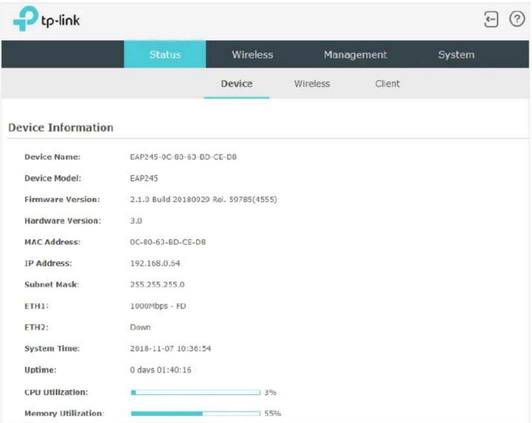
To monitor the EAP information, go to the Status > Device page.
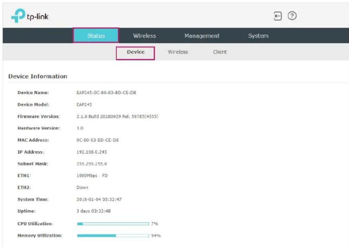
The following device information is displayed:
| Device Name Displays the name of the EAP. The name consists of the product model followed with the MAC address of the EAP by default. | |
| Device Model Displays the product model of the EAP. | |
| Firmware Version | Displays the current firmware version the EAP. To update the firmware, you can refer to 5.6 Update the Firmware. |
| Hardware Version Displays the hardware version the EAP. | |
| MAC Address Displays the MAC address of the EAP. | |
| IP Address Displays the IP address of the EAP. | |
| Subnet Mask Displays the subnet mask of the EAP. | |
| System Time Displays the current system time. To configure the system time, you can refer to 5.3 Configure the System Time. | |
| Uptime Displays how long the EAP has been working since it starts up. | |
CPU Utilization Displays the CPU occupancy. If this value is too high, the EAP may work abnormally.
Memory Utilization Displays the memory occupancy.
3.2 Monitor the Wireless Parameters
You can view the wireless parameters of the EAP, including SSID lists, radio settings, radio traffic and LAN traffic.
Tips:
To change the wireless parameters, you can refer to 2.1 Configure the Wireless Parameters
To monitor the wireless parameters, go to the Status > Wireless page.

Monitor the SSIDs
You can monitor the SSID information of the EAP.

tp-link


Status
Wireless
Management
System
Device
Wireless
Client
SSID List Refresh
| ID | SSID Name | Clients | Band | Security | Portal | VLAN ID | Guest Network | Down (Byte) | Up (Byte) |
| 1 | SSID-1 | 0 | 2.4GHz | WPA-PSK | Disable | Disable | Disable | 922k | 82k |
| 2 | SSID-2 | 0 | 5GHz | None | Disable | Disable | Disable | 12k | 2k |
The following table introduces the displayed information of the SSID:
SSID Name: Displays the SSID name.
Clients: Displays the number of clients currently connected to the SSID.
Band: Displays the frequency band the SSID is currently using.
Security: Displays the security mode of the SSID.
Portal: Displays whether the portal function is enabled on the SSID.
VLAN ID: Displays the VLAN ID of the SSID.
Guest Network: Displays whether the guest network is enabled on the SSID.
Down (Byte): Displays the total download traffic since the SSID starts working.
Up (Byte): Displays the total upload traffic since the SSID starts working.
Monitor the Radio Settings
You can monitor the radio settings of the EAP. For a dual-band EAP, there are two bands: 2.4GHz and 5GHz. You can click to select a band to view. The following figure, shown in the introduction, takes 2.4GHz as an example.
Radio Settings
2.4GHz
5GHz
2.4GHz Wireless Radio:
Enable
Channel Frequency:
6 / 2437MHz
Channel Width:
20/40MHz
IEEE802.11 Mode:
b/g/n mixed
Max TX Rate:
300.0Mbps
Tx Power:
20dBm
The following table introduces the displayed information of the EAP.
2.4GHz/5GHz
Displays whether wireless function is enabled on the radio band.
Wireless Radio
Channel Frequency Displays the channel and frequency which are currently used by the EAP.
Channel Width Displays the channel width which is currently used by the EAP.
IEEE802.11 Mode Displays the IEEE802.11 protocol currently used by the EAP.
Max TX Rate Displays the maximum physical rate of the EAP.
Tx Power Displays the transmit power of the EAP.
Monitor Radio Traffic
You can monitor the radio traffic of the EAP. For a dual-band EAP, there are two bands: 2.4GHz and 5GHz. You can click to select a band to view. The following figure posted in the introduction takes 2.4GHz as an example.
Radio Traffic
2.4GHz
5GHz
Rx Packets:
82874437
Tx Packets:
8800930
Rx Bytes:
20906526476
Tx Bytes:
1990845129
Rx Dropped Packets:
0
Tx Dropped Packets:
0
Rx Errors:
0
Tx Errors:
65
The following traffic information of the radio is displayed:
| Rx Packets Displays the total number of the received packets on the 2.4GHz/5GHz band since the EAP starts up. | |
| Tx Packets Displays the total number of the sent packets on the 2.4GHz/5GHz band since the EAP starts up. | |
| Rx Bytes Displays the total received traffic on the 2.4GHz/5GHz band since the EAP starts up. | |
| Tx Bytes Displays the total sent traffic on the 2.4GHz/5GHz band since the EAP starts up. | |
| Rx Dropped Packets | Displays the total number of the dropped packets which are received on the 2.4GHz/5GHz band since the EAP starts up. |
| Tx Dropped Packets | Displays the total number of the dropped packets which are sent on the 2.4GHz/5GHz band since the EAP starts up. |
| Rx Errors Displays the total number of error packets which are received on the 2.4GHz/5GHz band since the EAP starts up. | |
| Tx Errors Displays the total number of error packets which are sent on the 2.4GHz/5GHz band since the EAP starts up. | |
Monitor LAN Traffic
You can view the LAN traffic of the EAP.
| LAN Traffic | |||
| Rx Packets: | 559223 | Tx Packets: | 206607 |
| Rx Bytes: | 320073875 | Tx Bytes: | 204207153 |
| Rx Dropped Packets: | 0 | Tx Dropped Packets: | 0 |
| Rx Errors: | 0 | Tx Errors: | 0 |
The following traffic information of the LAN is displayed:
Rx Packets: Displays the total number of received packets in the LAN since the EAP starts up.
Tx Packets: Displays the total number of sent packets in the LAN since the EAP starts up.
Rx Bytes: Displays the total received traffic in the LAN since the EAP starts up.
Tx Bytes: Displays the total sent traffic in the LAN since the EAP starts up.
| Rx Dropped Packets | Displays the total number of the dropped packets which are received by the EAP since it starts up. |
| Tx Dropped Packets | Displays the total number of the dropped packets which are sent by the EAP since it starts up. |
| Rx Errors Displays the total number of the received error packets since the EAP starts up. | |
| Tx Errors Displays the total number of the sent error packets since the EAP starts up. | |
3.3 Monitor the Clients
You can monitor the information of the clients connected to the EAP.
To monitor the client information, go to the Status > Client page.

View Client Information
There are two types of clients: users and portal authenticated guests. Users are the clients that connect to the SSID with portal authentication disabled. Guests are the clients that connect to the SSID with portal authentication enabled.
Click the User or Guest tab to select the client types to view the information of the EAP. The following figure, shown in the introduction, takes user as an example.
| ID | Hostname | IP Address | MAC Address | Band | SSID | Active Time | Up (Byte) | Down (Byte) | RSSI (dBm) | Rate (Mbps) | Action |
| 1 | iPhone | 192.168.1.100 | D0-A6-37-83-DA-99 | 5GHz | SSID-2 | 0 days 00:00:07 | 4k | 1k | -80 | 175.0 |
The following client information is displayed:
Hostname: Displays the hostname of the user.
IP Address: Displays the IP address of the user.
MAC Address: Displays the MAC address of the user.
Band: Displays the frequency band the user is working on.
SSID: Displays the SSID the user is connecting to.
Active Time: Displays how long the user has been connected to the SSID.
Up (Byte): Displays the user's total uploaded traffic to the EAP since the last connection.
Down (Byte): Displays the user's total downloaded traffic from the EAP since the last connection.
RSSI (dBm): Displays the RSSI (Received Signal Strength Indication) of the user.
Rate (Mbps): Displays the wireless transmission rate of the user.
You can execute the corresponding operation to the EAP by clicking an icon in the Action column.

Click the icon to configure the rate limit of the client to balance bandwidth usage. Enter the download limit and upload limit and click OK.
You can limit the download and upload rate for each client that connects to specific SSIDs when configuring SSIDs. Refer to 2.1.1 Configure SSIDs for more details.
Note that the download and upload rate will be limited to the smaller value if you set the limit value both in SSID and client configuration.


Click the icon to block the access of the client to the network.
View Block Client Information
You can view the information of the clients that have been blocked and resume the client's access.
Block Client List
| ID | Hostname | MAC Address | Up (Byte) | Down (Byte) | Action |
| 1 | android-6532c20e9aa005cc | 1C-77-F6-91-C7-B8 | 3k | 1k |
The following information of the blocked client is displayed:
Hostname Displays the hostname of the user.
MAC Address Displays the MAC address of the user.
Up (Byte) Displays the user's total uploaded traffic to the EAP since the last connection.
Down (Byte) Displays the user's total downloaded traffic from the EAP since the last connection.
Action
You can click the

to resume the client's access to the internet.
4 Manage the EAP
The EAP provides powerful functions of device management and maintenance. This chapter introduces how to manage the EAP, including:
• 4.1 Manage the IP Address of the EAP • 4.2 Manage System Logs • 4.3 Configure Web Server • 4.4 Configure Management Access • 4.5 Configure LED • 4.6 Configure Wi-Fi Control (Only for Certain Devices) • 4.7 Configure PoE Out (Only for Certain Devices) • 4.8 Configure SSH • 4.9 Configure SNMP
4.1 Manage the IP Address of the EAP
The IP address of the EAP can be a dynamic IP address assigned by the DHCP server or a static IP address manually specified by yourself. By default, the EAP gets a dynamic IP address from the DHCP server. You can also specify a static IP address according to your needs.
Tips:
For detailed introduction about how to find the dynamic IP address of the EAP, refer to Using Web Browser on Your PC and Connecting to the Ethernet
To configure the IP address of the EAP, go to the Management > Network page.

Follow the steps below to configure the IP address of the EAP:
- Choose your desired IP address mode: Dynamic or Static.
- Configure the related parameters according to your selection.
• Dynamic
If you choose Dynamic as the IP address mode, make sure that there is a reachable DHCP server on your network and the DHCP sever is properly configured to assign IP address and the other network parameters to the EAP.

For network stability, you can also configure the fallback IP parameters for the EAP:
Fallback IP With the fallback IP configured, if the EAP fails to get an IP address from a DHCP server within 10 seconds, the fallback IP will work as the IP address of the EAP. After that, however, the EAP will keep trying to obtain an IP address from the DHCP server until it succeeds.
DHCP Fallback IP Specify a fallback IP address for the EAP. Make sure that this IP address is not being used by any other device in the same LAN. The default DHCP fallback IP is 192.168.0.254.
DHCP Fallback IP MASK Specify the network mask of the fallback IP. The default DHCP fallback IP mask is 255.255.255.0.
DHCP Fallback Gateway Specify the network gateway.
- Static
If you choose Static as the IP address mode, you need to manually specify an IP address and the related network parameters for the EAP. Make sure that the specified IP address is not being used by any other device in the same LAN.

Configure the IP address and network parameters as shown in the following table:
IP Address: Specify a static IP address for the EAP.
IP Mask: Specify the network mask.
Gateway: Specify the network gateway.
Primary DNS: Specify the primary DNS server.
Secondary DNS: Specify the secondary DNS server. (Optional)
- Click Save.
4.2 Manage System Logs
System logs record information about hardware, software, and system issues, and monitor system events. With the help of system logs, you can get informed of system running status and detect the reasons for failure.
To manage system logs, go to the Management > System Log page.

On this page, you can view the system logs and configure the way of receiving system logs.
View System Logs
In the Log section, you can click to refresh the logs and view them in the table.
Log
| Index | Time | Type | Level | Log Content |
| 2 | 1970-01-01 00:00:12 | OTHER | WARNING | LAN IP and mask changed to 192.168.0.220 255.255.255.0 |
| 1 | 1970-01-01 00:00:07 | OTHER | INFO | System started |
Configure the Way of Receiving Logs
In the Log Settings section, you can configure the ways of receiving system logs.
Log Settings
Enable Auto Mail:
□ Enable
Enable Server:
□ Enable
Save
Follow the steps below to configure this feature:
- Check the corresponding box to enable one or more ways of receiving system logs, and configure the related parameters. Two ways are available: Auto Mail and Server.
■ Auto Mail
If Auto Mail is configured, system logs will be sent to a specified mailbox. Check the box to enable the feature and configure the related parameters.
Note:
SSL encryption is not currently supported.

The following table introduces how to configure these parameters:
| From Enter the sender's E-mail address. | |
| To Enter the receiver's E-mail address. | |
| SMTP Server Enter the IP address of the sender's SMTP server. | |
| Note: At present, the domain name of SMTP server is not supported in this field. | |
| Enable Authentication | If the sender's mailbox is configured with You can check the box to enable mail server authentication. Enter the sender's username and password. |
| Time Mode | Select Time Mode: Fixed Time or Period Time.Fixed Time means that the system logs will be sent at the specific time every day. Period Time means that the system logs will be sent at the specific time interval. |
| Fixed Time | If you select Fixed Time, specify a fixed time to send the system log mails. For example, 08:30 indicates that the mail will be sent at 8:30 am everyday. |
| Period Time | If you select Period Time, specify a period time to regularly send the system log mail. For example, 6 indicates that the mail will be sent every six hours. |
■ Server
If Server is configured, system logs will be sent to the specified system log server, and you can use the syslog software to view the logs on the server.
Enable this feature and enter the IP address and port of the system log server.

System Log Server IP: Enter the IP address of the server.
System Log Server Port: Enter the port of the server.
More Client Detail Log: With the option enabled, the logs of clients will be sent to the server.
2. Click Save.
4.3 Configure Web Server
With the web server, you can log in to the management web page of the EAP. You can configure the web server parameters of the EAP according to your needs.
To configure Web Server, go to the Management > Web Server page.

Follow the steps below to configure Web Server:
- Refer to the following table to configure the parameters:
| Secure Server Port Designate a secure server port for web server in HTTPS mode. By default the port is 443. | |
| Server Port Designate a server port for web server in HTTP mode. By default the port is 80. | |
| Session Timeout Set the session timeout. If you do nothing with the web page within the timeout, the system will log out automatically. You can log in again if you want to go back to web page. | |
| Layer-3Accessibility | With this feature enabled, devices from a different subnet can access Omada managed devices via the management web page. With this feature disabled, only the devices in the same subnet can access Omada managed devices via the management web page. |
- Click Save.
4.4 Configure Management Access
By default, all hosts in the LAN can log in to the management web page of the EAP with the correct username and password. To control the hosts' access to the web page of the EAP, you can specify the MAC addresses and management VLAN of the hosts that are allowed to access the web page.
To configure Management Access, go to the Management > Management Access page.

Configure Access MAC Management
Only the hosts with the specific MAC addresses are allowed to access the web page, and other hosts without MAC addresses specified are not allowed to access the web page.
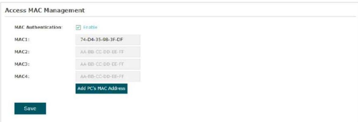
Follow the steps below to configure Management Access on this page:
- Check the box to enable MAC Authentication.
- Specify one or more MAC addresses in the MAC1/MAC2/MAC3/MAC4 fields. Up to four MAC addresses can be added.
- Click Save.
Tips:
- You can click Add PC's MAC Address to quickly add the MAC address of your current logged-in host.
- Verify the MAC addresses carefully. Once the settings are saved, only the hosts in the MAC address list can access the web page of the EAP.
- If you cannot log in to the web page after saving the wrong configuration, you can reset the EAP to the factory defaults and use the default username and password (both admin) to log in.
Configure Management VLAN
Management VLAN provides a safer method to manage the EAP. With Management VLAN enabled, only the hosts in the Management VLAN can access the web page of the EAP. Since most hosts cannot process VLAN TAGs, you can connect the management host to the network via a switch, and set up correct VLAN settings for the switches on the network to ensure the communication between the host and the EAP in the Management VLAN.

Follow the steps below to configure Management VLAN on this page:
- Check the box to enable Management VLAN.
- Specify the VLAN ID of the management VLAN. Only the hosts in the Management VLAN can log in to the EAP via the Ethernet port.
- Click Save.
4.5 Configure LED
You can turn on or off the LED light of the EAP and flash the LED to locate your device.
To configure LED, go to the Management > LED Control page.

Check the box to turn on or turn off the LED light of the EAP, and click Save. To flash the LED, click Locate. Then the LED will flash for 10 minutes or until the locate button is clicked again.
4.6 Configure Wi-Fi Control (Only for Certain Devices)
Note:
Wi-Fi Control is only available on certain devices. To check whether your device supports this feature, refer to the actual web interface. If Wi-Fi Control is available, there is Management > Wi-Fi Control in the menu structure.
Certain devices have an LED/Wi-Fi button on the front panel. With Wi-Fi Control enabled, you can press the button to turn on or off both of the Wi-Fi and LED at the same time.
To configure Wi-Fi Control, go to the Management > Wi-Fi Control page.

Check the box to enable Wi-Fi Control and click Save.
Note:
You can enable Wi-Fi Control only when the option LED ON/OFF is enabled.
4.7 Configure PoE Out (Only for Certain Devices)
Note:
PoE Out is only available on certain devices. To check whether your device supports this feature, refer to the actual web interface. If PoE Out is available, there is Management > LAN Port Config in the menu structure.
Certain devices have a PoE OUT port that can transmit data and supply power to the client simultaneously. You can also disable PoE Out to make the port transmit data only.
To configure PoE Out, go to the Management > LAN Port Config page.

Check the box to enable PoE Out and click Save.
4.8 Configure SSH
If you want to remotely log in to the EAP via SSH, you can deploy an SSH server on your network and configure the SSH feature on the EAP.
To configure SSH, go to the Management > SSH page.
![tp-link Status Wireless Management System Network System Log Web Server Management Access LED Control SSH SNMP SSH Server Server Port: 22 [22,1025-65535] Layer-3 Accessibility: Enable SSH Login: Enable Save](/content/2026/06/1377910/images/26144760bc87f01a9f387bf99f3b3ece3a915e20032fe5d9ce888aa09426c649.jpg)
Follow the steps below to configure SSH on this page:
- Refer to the following table to configure the parameters:
Server Port Designate a server port for SSH. By default the port is 22.
Layer-3 Accessibility With this feature enabled, devices from a different subnet can access Omada managed devices via SSH. With this feature disabled, only the devices in the same subnet can access Omada managed devices via SSH.
SSH Login Enable or disable SSH Login globally.
- Click Save.
4.9 Configure SNMP
The EAP can be configured as an SNMP agent and work together with the SNMP manager. Once the EAP has become an SNMP agent, it is able to receive and process request messages from the SNMP manager. At present, the EAP supports SNMP v1 and v2c.
To configure the EAP as an SNMP agent, go to the Management > SNMP page.

Follow the steps below to complete the configuration on this page:
- Check the box to enable SNMP Agent.
- Refer to the following table to configure the required parameters:
SysContact: Enter the textual identification of the contact person for this managed node.
SysName: Enter an administratively-assigned name for this managed node.
SysLocation: Enter the physical location of this managed node.
Get Community: Community refers to a host group aiming at network management.
Get Community only has the read-only right of the device's SNMP information. The community name can be considered a group password. The default setting is public.
Get Source: Defines the IP address (for example, 10.10.10.1) for management systems that can serve as Get Community to read the SNMP information of this device. The default is 0.0.0.0, which means all hosts can read the SNMP information of this device.
Set Community: Set Community has the read and write right of the device's SNMP information. Enter the community name that allows read/write access to the device's SNMP information. The community name can be considered a group password. The default setting is private.
Set Source: Defines the IP address (for example, 10.10.10.1) for management systems that can serve as Set Community to read and write the SNMP information of this device. The default is 0.0.0.0, which means all hosts can read and write the SNMP information of this device.
3. Click Save.
Note:
Defining a community allows management systems within the same community to communicate with the SNMP Agent. The community name can be seen as a shared password for the group of network hosts. Therefore, for security reasons, we recommend that you modify the default community name before enabling the SNMP Agent service. If the community field is left blank, the SNMP Agent will not respond to any community name.
5 Configure the System
This chapter introduces how to configure the system of the EAP, including:
• 5.1 Configure the User Account • 5.2 Controller Settings • 5.3 Configure the System Time • 5.4 Reboot and Reset the EAP • 5.5 Backup and Restore the Configuration • 5.6 Update the Firmware
5.1 Configure the User Account
Every EAP has a user account, which is used to log in to the management page of the EAP. When you start the EAP for the first time, the username and password of the user account are both 'admin'. After the first login, the system will require you to set a new username and a new password for the user account. Then you can use the new user account to log in to the EAP. Also, you can change your user account as needed.
Tips:
Please remember your user account well. If you forget it, reset the EAP to the factory defaults and log in with the default user account (username and password are both 'admin').
To configure the user account, go to the System > User Account page.

Follow the steps below to change your user account on this page:
- Enter the old username and old password of your user account.
- Specify a new username and a new password for your user account. The system will automatically detect the strength of your entered password. For security, we recommend that you set a password with high strength.
- Retype the new password.
- Click Save.
5.2 Controller Settings
To make your controller adopt your EAP, ensure that the EAP can be discovered by the controller. Controller Settings enable your EAP to be discovered in either of the following scenarios.
- If you are using Omada Cloud-Based Controller, enable Cloud-Based Controller Management.
- If your EAP and controller are located in the same network, LAN, and VLAN, the controller can discover and adopt the EAP without any controller settings. Otherwise, you need to inform the EAP of the controller's URL/IP address, and one possible way is to configure the Controller Inform URL.
For details about the whole procedure, refer to the User Guide of Omada SDN Controller. The guide can be found on the download center of our official website: https://www.tp-link.com/support/download/
Enable Cloud-Based Controller Management
Go to the System > Controller Settings page. In the Cloud-Based Controller Management section, enable Cloud-Based Controller Management and click Save. After you add the
EAP to your Omada Cloud-Based Controller, you can check the connection status on this page.

Configure Controller Inform URL
Go to the System > Controller Settings page. In the Controller Inform URL section, inform the EAP of the controller's URL/IP address, and click Save. Then the EAP makes contact with the controller so that the controller can discover the EAP.
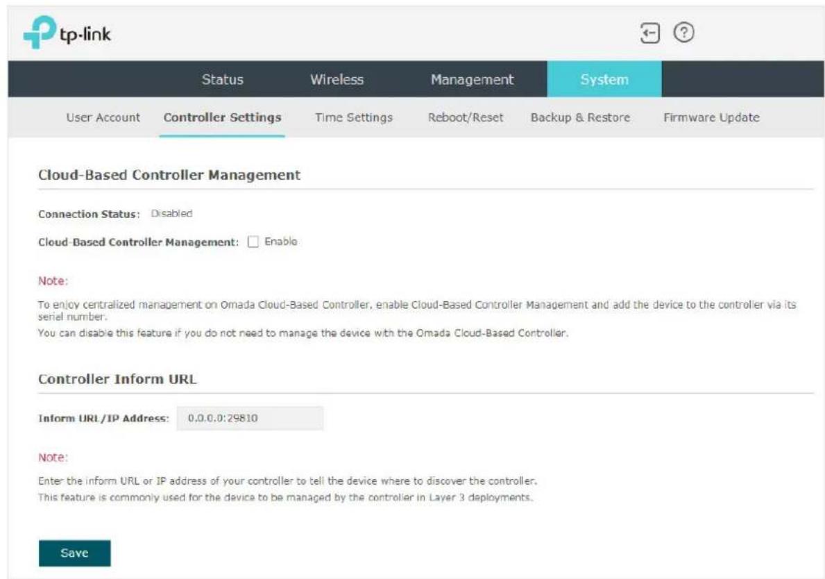
5.3 Configure the System Time
System time is the standard time for Scheduler and other time-based functions. The EAP supports the basic system time settings and the Daylight Saving Time (DST) feature.
To configure the system time, go to the System > Time Settings page.

The following two sections introduce how to configure the basic system time settings and the Daylight Saving Time feature.
Configure the System Time
In the Time Settings section, you can configure the system time. There are three methods to set the system time: Set the System Time Manually, Acquire the System Time From an NTP Server, and Synchronize the System Time with PC's Clock.
![Time Settings Time zone: [GMT+08:00] Beijing, Hong Kong, Perth, Singapore Date: 06/01/2017 MM/DD/YYYY Time: 14 : 36 : 21 (HH/MM/SS) Primary NTP Server: (optional) Secondary NTP Server: (optional) Get GMT Synchronize with PC Save](/content/2026/06/1377910/images/ee9eefaf630a692f802eeb7a3318e31a3877040aa535726ac51d03a55cb77218.jpg)
Determine the way of setting the system time and follow the steps below to complete the configurations:
- Set the System Time Manually
To set the system time manually, follow the steps below:
- Configure the following three options on the page: Time Zone, Date and Time.
Time Zone: Select your time zone from the drop-down list. Here GMT means Greenwich Mean Time.
Date: Specify the current date in the format MM/DD/YYYY. MM means month, DD means day and YYYY means year. For example: 06/01/2017.
Time: Specify the current time in the format HH:MM:SS. HH means hour, MM means minute and SS means second. It uses 24-hour system time. For example: 14:36:21.
- Click Save.
Note:
The system time set manually will be lost after the EAP is rebooted.
- Acquire the System Time From an NTP Server
To get the system time from an NTP server, follow the steps below:
- Build an NTP server on your network and make sure that it is reachable by the EAP. Or you can simply find an NTP server on the internet and get its IP address.
Note:
If you use an NTP server on the internet, make sure that the gateway address is set correctly on the EAP. Otherwise, the EAP cannot get the system time from the NTP server successfully. To set the gateway address, refer to 2.1 Configure the Wireless Parameters
- Specify the NTP server for the EAP. If you have two NTP servers, you can set one of them as the primary NTP server, and the other as the secondary NTP server. Once the primary NTP server is down, the EAP can get the system time from the secondary NTP server.
| Primary NTP Server | Enter the IP address of the primary NTP server. Note: If you have only one NTP server on your network, enter the IP address of the NTP server in this field. |
| Secondary NTP Server | Enter the IP address of the secondary NTP server. |
- Click the button Get GMT and the acquired system time will be displayed in the Date and Time fields.
- Click Save.
- Synchronize the System Time with PC's Clock
To synchronize the system time with the clock of your currently logged-in host, follow the steps below:
- Click the button synchronized system time will be displayed in the Date and Time fields.
- Click Save.
Note:
The system time synchronized with PC's clock will be lost after the EAP is rebooted.
Configure Daylight Saving Time
Daylight saving time is the practice of advancing clocks during summer months so that evening daylight lasts longer, while sacrificing normal sunrise times. The EAP provides daylight saving time configuration.
Daylight Saving
Daylight Saving:
□ Enable
Mode:
Predefined Mode
☐ Recurring Mode
Date Mode
Predefine Country:
European
Save
Follow the steps below to configure daylight saving time:
- Check the box to enable Daylight Saving.
- Select the mode of daylight saving time. Three modes are available: Predefined Mode, Recurring Mode and Date Mode.
- Configure the related parameters of the selected mode.
■ Predefined Mode
If you select Predefined Mode, choose your region from the drop-down list and the EAP will use the predefined daylight saving time of the selected region.
Mode:

Predefined Mode

Recurring Mode

Date Mode
Predefine Country:
European
There are four regions provided: USA, European, Australia and New Zealand. The following table introduces the predefined daylight saving time of each region.
USA: From 2:00 a.m. on the Second Sunday in March to 2:00 a.m. on the First Sunday in November.
European: From 1:00 a.m. on the Last Sunday in March to 1:00 a.m. on the Last Sunday in October.
Australia: From 2:00 a.m. on the First Sunday in October to 3:00 a.m. on the First Sunday in April.
New Zealand: From 2:00 a.m. on the Last Sunday in September to 3:00 a.m. on the First Sunday in April.
■ Recurring Mode
If you select Recurring Mode, manually specify a cycle time range for the daylight saving time of the EAP. This configuration will be used every year.

The following table introduces how to configure the cycle time range.
Time Offset: Specify the time to set the clock forward by.
Start: Specify the start time of daylight saving time. The interval between the start time and end time should be more than 1 day and less than 1 year (365 days).
End: Specify the end time of daylight saving time. The interval between the start time and end time should be more than 1 day and less than 1 year (365 days).
■ Date Mode
If you select Date Mode, manually specify an absolute time range for the daylight saving time of the EAP. This configuration will be used only once.

The following table introduces how to configure the absolute time range.
Time Offset: Specify the time to set the clock forward by.
Start: Specify the start time of daylight saving time. The interval between the start time and end time should be more than 1 day and less than 1 year (365 days).
End: Specify the end time of daylight saving time. The interval between the start time and end time should be more than 1 day and less than 1 year (365 days).
- Click Save.
5.4 Reboot and Reset the EAP
You can reboot and reset the EAP according to your need.
To reboot and reset the EAP, go to the System > Reboot&Reset page.
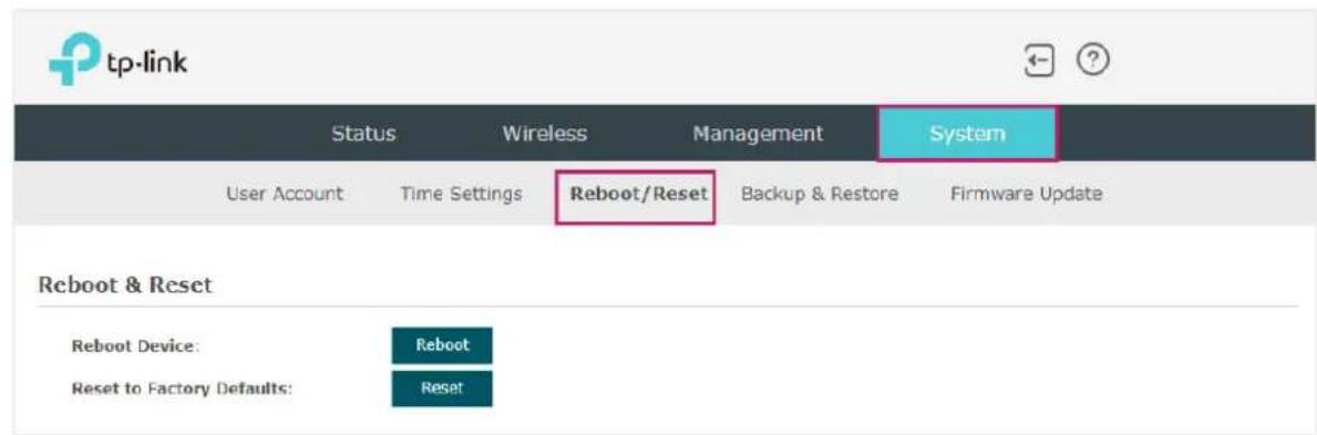
- To reboot the EAP, click the Reboot button, and the EAP will be rebooted automatically. Please wait without any operation.
- To reset the EAP, click the Reset button, and the EAP will be reset to the factory defaults automatically. Please wait without any operation.
Note:
After reset, all the current configuration of the EAP will be lost. We recommend that you check whether you have any configuration that needs to be backed up before resetting the EAP.
5.5 Backup and Restore the Configuration
You can save the current configuration of the EAP as a backup file and save the file to your host. And if needed, you can use the backup file to restore the configuration. We recommend that you backup the configuration before resetting or upgrading the EAP.
To backup and restore the configuration, go to the System > Backup&Restore page.

- To backup the configuration, click the button in Backup section, and the backup file will be saved to the host automatically.
- To restore the configuration, click the button Browse in the Restore section and choose the backup file from the host. Then click the button Restore to restore the configuration.
5.6 Update the Firmware
We occasionally provide the firmware update files for the EAP products on our official website. To get new functions of the EAP, you can check our official website and download the update files to update the firmware of your EAP.
To update the firmware, go to the System > Firmware Update page.
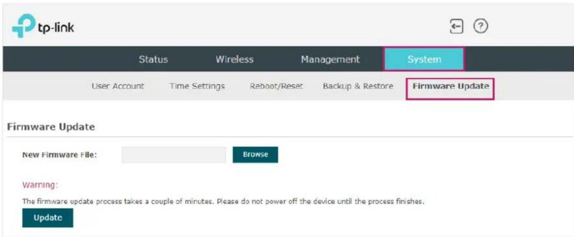
Follow the steps below to update the firmware of your EAP:
- Go to our website https://www.tp-link.com and search your EAP model. Download the proper firmware file on the support page of the EAP.
- Click the button Browse, locate and choose the correct firmware file from your host.
- Click the button Update to update the firmware of the EAP. After updated, the EAP will be rebooted automatically.
Note:
The update process takes several minutes. To avoid damage to the EAP, please wait without any operation until the update is finished.
Application Example
This chapter provides an application example about how to establish and manage a EAP wireless network:
A restaurant wants to provide the wireless internet access for the employees and guests. The restaurant now has a router, a switch, a dual-band EAP and a computer. Follow the steps below to establish the wireless network:
- 6.2 Build the Network Topology
- 6.3 Log in to the EAP
- 6.4 Configure the EAP 5.6.5 Test the Network
- 6.1 Determine the Network Requirements
6.1 Determine the Network Requirements
Before starting to build the network, we need to first analyze and determine the network requirements. In this restaurant example, the network requirements are as follows:
- On both 2.4GHz and 5GHz bands, there are two SSIDs needed: one for the restaurant employees and one for the guests.
- In order to advertise the restaurant, the Portal feature needs to be configured on the SSIDs for the guests. In this way, the guests who have passed the portal authentication will be redirected to the restaurant's official website http://www.restaurant1.com.
- The employees of the restaurant can use the correct password to access the internet and do not need to pass the portal authentication. For security, the SSIDs for the employees should be encrypted with WPA2-PSK.
- To reduce power consumption, the Scheduler feature needs to be configured. The radio should operate only during the working time (9:00 am to 22:00 pm).
6.2 Build the Network Topology
Build the network topology as the following figure shows.
![graph LR A["Management Host"] --> B["Switch"] B --> C["Router (DHCP Server)\nLAN: 192.168.88.1"] B --> D["EAP"] C --> E["Internet"]](/content/2026/06/1377910/images/882dcf15db48d0a85e6fa13ef9d29edac4e6a78c96e898c0fce1e1a6ed2e5788.jpg)
- The router is the gateway of the network and acts as a DHCP server to assign dynamic IP addresses to the management host, EAP and clients. The LAN IP of the router is 192.168.88.1/24.
- Connect the switch to the LAN port of the router.
- Connect the management host and the EAP to the switch. The IP address mode of the management host and EAP is dynamic, which means that they will get dynamic IP addresses from the router.
Tips:
If the router has more than one LAN port, we can also respectively connect the management host and the EAP to the LAN ports of the router.
6.3 Log in to the EAP
After building the network topology, follow the steps below to log in to the web page of the EAP:
- On the management host, launch the web browser and enter "192.168.88.1" in the address bar. Then log in to the router and find the IP address of the EAP. As the following figure shows, the IP address of the EAP is 192.168.88.101.
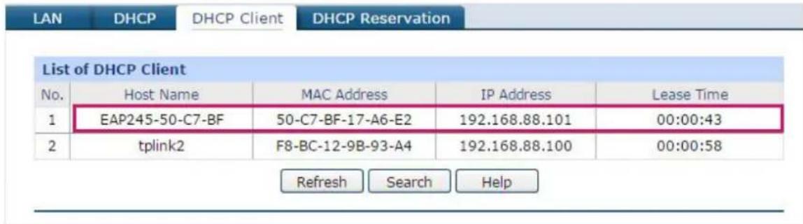
- Enter "192.168.88.101" in the address bar to load the login page of the EAP. Type the default username and password (both admin) in the two fields and click LOGIN.

- In the pop-up window, specify a new username and a new password for the user account. Click Next.
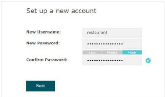
6.4 Configure the EAP
To achieve the network requirements in this application example, we need to configure SSIDs, configure Portal Authentication, and configure a Scheduler.
Configure SSIDs
- After logging in to the EAP, follow the step-by-step instructions to complete the basic configurations for creating SSIDs. Configure the SSIDs as "employee_2.4GHz" and "employee_5GHz", specify the password as "restaurant123abc", and click Save.

tp-link
Wireless Basic Settings
2.4GHz Wireless Radio:
SSID:
Password:
Enable
employee-2.4GHz
restaurant123abc
5GHz Wireless Radio:
SSID:
Password:
Enable
employee-5GHz
restaurant123abc
Back
Save
- Go to the Wireless > Wireless Settings page. Create SSIDs for guests on 2.4GHz. Click

Add to add a new SSID.
2.4GHz SSIDs
| ID | SSID | VLAN ID | SSID Broadcast | Security Mode | Guest Network | Action |
| 1 | employees-2.4GHz | 0 | Enable | WPA-PSK | Disable |
- The following page will appear. Configure this SSID as "guest_2.4GHz", keep the Security Mode as "None" and check the box to enable the Portal feature for this SSID. Click OK.
2.4GHz SSIDs
| ID | SSID | VLAN ID | SSID Broadcast | Security Mode | Guest Network | Action |
| - | - | - | - | - | - | - |
| SSID: guest-2.4GHz | ||||||
| SSID Broadcast: Enable | ||||||
| Security Mode: None | ||||||
| Guest Network: Enable | ||||||
| Rate Limit: Enable | ||||||
| OK Cancel | ||||||
| 1 | employee-2.4GHz | 0 | Enable | WPA-PSK | Disable | |
- Click to enter the configuration page for the 5GHz band. Similarly to the configurations for the 2.4GHz band, configure another SSID for the guests on the 5GHz band.
Configure Portal Authentication
Follow the steps below to configure portal authentication:
- Go to the Wireless > Portal page.
- Configure the portal feature as the following figure shows.

1) Select the SSIDs for the guests on which the portal will take effect. 2) Select the Authentication Type as "Local Password" and specify the Password as "restaurant123". 3) Configure Authentication Timeout. Here we customize the timeout as 2 hours. This means that guests will be logged out after they have been authenticated for 2 hours. To continue using the internet service, these guests need to enter the password to pass the portal authentication once again. 4) Check the box to enable Redirect, and enter the website of the restaurant: http://www.restaurant1.com.
5) Configure the authentication page. Specify the title and the terms of use. To access the internet, guests need to enter the correct password in the Password field, accept the Terms of Use, and click the Login button.
- Click Save.
Configure Scheduler
Follow the steps below to schedule the radio to operate only during working hours (9:00 am to 10:00 pm).
- Go to the Wireless > Scheduler page.
- In the Settings section, check the box to enable Scheduler, and select the Association Mode as "Associated with AP". Click Save.
Settings
Scheduler:
Association Mode:

Associated with AP

Save
- In the Scheduler Profile Configuration section, click

Create Profiles
Scheduler Profile Configuration

Create Profiles
1) The following page will appear. Click and specify the profile name as "worktime". Click OK.
Scheduler Profile Configuration
2) Choose the newly added profile "worktime", and click . Then the item configuration page will appear. Specify the time range as everyday 9:00 to 22:00. Click OK.

- In the Scheduler Association section, select "worktime" in the Profile Name column and select "Radio On" in the Action column. Click Save.
Scheduler Association
| ID | AP | AP MAC | Profile Name | Action |
| 1 | EAP245-50-c7-bf-17-a6-e2 | 50-C7-BF-17-A6-E2 | worktime | Radio On |
Save
6.5 Test the Network
To ensure that the employees and guests can surf the internet via the wireless network, we can use a client device, such as a telephone, to test whether the SSIDs are working normally.
• To test the SSIDs for the employees, follow the steps below:
1) Enable the Wi-Fi feature of the client device. 2) Choose the SSID "employee_2.4GHz" or "employee_5GHz" among the detected SSIDs. 3) Enter the password "restaurant123abc" to join the wireless network. 4) Check whether internet websites can be visited successfully.
• To test the SSIDs for the guests, follow the steps below:
1) Enable the Wi-Fi feature of the client device. 2) Choose the SSID "guest_2.4GHz" or "guest_5GHz" among the detected SSIDs. 3) The default web browser on the device will pop up and the authentication page will appear. Enter the password "restaurant123", check the box to accept the term of use, and click the LOGIN button.

Tips:
Generally, the web browser pops up automatically. But if the web browser does not pop up, we can manually launch the web browser and visit any http website. Then the authentication page will appear.
4) If the network is working normally, we will be redirected to the website of the restaurant: http://www.restaurant1.com.

COPYRIGHT & TRADEMARKS
Specifications are subject to change without notice. To an registered trademark of TP-Link Technologies Co., Ltd. Other brands and product names are trademarks or registered trademarks of their respective holders.
No part of the specifications may be reproduced in any form or by any means or used to make any derivative such as translation, transformation, or adaptation without permission from TP-Link Technologies Co., Ltd. Copyright © 2021 TP-Link Technologies Co., Ltd.. All rights reserved.
- ABOUT THIS USER GUIDE
- OVERVIEW
- QUICK START
- CONFIGURE THE NETWORK
- CONFIGURE PORTAL AUTHENTICATION
- CONFIGURE VLAN
- CONFIGURE MAC FILTERING
- CONFIGURE SCHEDULER
- CONFIGURE BAND STEERING
- CONFIGURE QOS
- CONFIGURE ROGUE AP DETECTION
- MONITOR THE NETWORK
- MANAGE THE EAP
- CONFIGURE THE SYSTEM
- APPLICATION EXAMPLE
- CONVENTIONS
- WIRELESS SPEED, RANGE AND CONNECTED DEVICES DISCLAIMER
- MU-MIMO DISCLAIMER (FOR EAPS THAT SUPPORT MU-MIMO)
- SEAMLESS ROAMING DISCLAIMER (FOR EAPS THAT SUPPORT SEAMLESS ROAMING)
- LIGHTNING AND ELECTRO-STATIC DISCHARGE PROTECTION DISCLAIMER (FOR OUTDOOR EAPS)
- MORE INFO
- DETERMINE THE MANAGEMENT METHOD
- CONTROLLER MODE
- STANDALONE MODE
- NOTE
- CONNECT NETWORK DEVICES
- TIPS
- LOG IN TO THE EAP AND CHANGE THE SSID
- USING WEB BROWSER ON YOUR PC AND CONNECTING TO THE ETHERNET
- SUCCESS
- CONFIGURE AND MANAGE THE EAP
- CONFIGURE THE WIRELESS PARAMETERS
- CONFIGURE SSIDS
- WEP
- WPA-ENTERPRISE
- WPA-PERSONAL
- CONFIGURE WIRELESS ADVANCED SETTINGS
- RADIO SETTING
- GHZ WIRELESS ADVANCED SETTINGS
- LOAD BALANCE
- AIRTIME FAIRNESS
- MORE SETTINGS
- CONFIGURE PORTAL
- NO AUTHENTICATION
- LOCAL PASSWORD
- EXTERNAL RADIUS SERVER
- CLICK SAVE
- CONFIGURE FREE AUTHENTICATION POLICY
- ASSOCIATION WITH SSID
- ASSOCIATION WITH AP
- DETECT ROGUE APS AND MOVE THE ROGUE APS TO THE TRUSTED AP LIST
- MANAGE THE TRUSTED AP LIST
- DOWNLOAD THE TRUSTED AP LIST FROM THE HOST
- DOWNLOAD/BACKUP TRUSTED AP LIST
- BACKUP THE TRUSTED AP LIST TO THE HOST
- MONITOR THE EAP
- MONITOR THE WIRELESS PARAMETERS
- MONITOR THE SSIDS
- MONITOR THE RADIO SETTINGS
- RADIO SETTINGS
- GHZ
- MONITOR RADIO TRAFFIC
- RADIO TRAFFIC
- MONITOR LAN TRAFFIC
- MONITOR THE CLIENTS
- VIEW CLIENT INFORMATION
- VIEW BLOCK CLIENT INFORMATION
- MANAGE THE IP ADDRESS OF THE EAP
- DYNAMIC
- STATIC
- MANAGE SYSTEM LOGS
- VIEW SYSTEM LOGS
- CONFIGURE THE WAY OF RECEIVING LOGS
- LOG SETTINGS
- AUTO MAIL
- SERVER
- CONFIGURE WEB SERVER
- CONFIGURE MANAGEMENT ACCESS
- CONFIGURE ACCESS MAC MANAGEMENT
- CONFIGURE MANAGEMENT VLAN
- CONFIGURE LED
- CONFIGURE WI-FI CONTROL (ONLY FOR CERTAIN DEVICES)
- CONFIGURE POE OUT (ONLY FOR CERTAIN DEVICES)
- CONFIGURE SSH
- CONFIGURE SNMP
- CONFIGURE THE USER ACCOUNT
- CONTROLLER SETTINGS
- ENABLE CLOUD-BASED CONTROLLER MANAGEMENT
- CONFIGURE CONTROLLER INFORM URL
- CONFIGURE THE SYSTEM TIME
- SET THE SYSTEM TIME MANUALLY
- ACQUIRE THE SYSTEM TIME FROM AN NTP SERVER
- SYNCHRONIZE THE SYSTEM TIME WITH PC'S CLOCK
- CONFIGURE DAYLIGHT SAVING TIME
- DAYLIGHT SAVING
- PREDEFINED MODE
- RECURRING MODE
- DATE MODE
- REBOOT AND RESET THE EAP
- BACKUP AND RESTORE THE CONFIGURATION
- UPDATE THE FIRMWARE
- DETERMINE THE NETWORK REQUIREMENTS
- BUILD THE NETWORK TOPOLOGY
- LOG IN TO THE EAP
- CONFIGURE THE EAP
- WIRELESS BASIC SETTINGS
- TEST THE NETWORK
- COPYRIGHT & TRADEMARKS
Brand : TP-LINK
Model : EAP610 V2
Category : Access Point