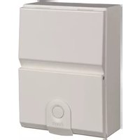
VM202K - Electrical panel HAGER - Free user manual and instructions
Find the device manual for free VM202K HAGER in PDF.


| Type of product | Voltage Monitor |
| Brand | Hager |
| Model | VM202K |
| Dimensions (W x H x D) | 85 mm x 55 mm x 35 mm |
| Weight | 0.1 kg |
| Power supply | 230 V AC, 50/60 Hz |
| Rated voltage | 230 V AC |
| Frequency | 50/60 Hz |
| Overvoltage threshold | Approximately 253 V AC |
| Undervoltage threshold | Approximately 207 V AC |
| Response time | Less than 1 second |
| Display type | LED indicators |
| Mounting type | DIN rail mount per EN 60715 |
| Operating temperature | -10°C to +50°C |
| Storage temperature | -20°C to +70°C |
| Protection rating | IP20 |
| Functions | Voltage monitoring, over/undervoltage protection, LED status indication |
| Maintenance | No maintenance required; check connections periodically |
| Safety standards | Complies with IEC 60669, IEC 60947, RoHS |
| Spare parts | Not user-serviceable; replace unit if faulty |
| Warranty | 2 years (subject to terms) |
Frequently Asked Questions - VM202K HAGER
User questions about VM202K HAGER
0 question about this device. Answer the ones you know or ask your own.
Ask a new question about this device
Download the instructions for your Electrical panel in PDF format for free! Find your manual VM202K - HAGER and take your electronic device back in hand. On this page are published all the documents necessary for the use of your device. VM202K by HAGER.
USER MANUAL VM202K HAGER
natural_image
Line drawing of a two-tiered rectangular box with a circular button on the side (no text or symbols)GB
Design 30 Consumer Unit Instructions/Data Sheet
This Consumer Unit and Hager devices conform with the following standards:
Consumer Unit: BS EN 61439-3 including Annex ZB.
Switch-disconnectors: BS EN 60947-3.
Residual Current Circuit Breaker (RCCB): BS EN 61008-1
Residual current operated circuit breaker with integral overload (RCBO): BS EN 61009-1
Miniature Circuit Breaker (MCB): BS EN 60898-1
Installation Instructions:
All product(s) must be installed by a suitably competent electrician Giving consideration to their intended use and in accordance with the current edition of BS 7671 (IET Wiring Regulations).
The Electricity at Work regulations and the Health and Safety at Work Act shall be complied with.
Only equipment and arrangements specified in Hager's technical documentation / catalogue shall be used.
Install in the horizontal plane only.
For guidance when making connections in a consumer unit electrical safety first /BEAMA document “Guidance for installers when making connections in consumer units” is available from hager.co.uk/63026.htm
Additional Extras
| Accessory Ref. | |
| Cable protector plateCan be used on the rear knockouts to smooth any sharp edges | Insulated:VM02CEMetal:VM01CE |
Important notice:
To prevent potential overheating from loose connections the installer shall check connections are tight to the torque levels stated in these instructions prior to energizing this board. This check should include factory made connections which may have loosened in transit.
Good workmanship and proper materials must be applied by the installer. The cable entry method shall, as far as reasonably practical, maintain the non-combustable arrangement of the enclosure. Account shall be taken of these instructions.
Removal of front cover:

Easy fit front cover assembly allows the cover to be located at the top of the board and locked Into place that enables the cover to stay secure when replacing or removing during an installation.
Wall Fixing:

The units have multiple fixing points that will suit No.8 & No.10 screws
Cable entry facilities:

Where Electrical Knockouts are provided for top or bottom cable entry are sized and positioned to suit standard trunking i.e 100x50mm, 50x50mm & 40x25mm, grommet strip is provide to protect the cables when entering the board.
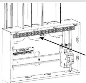
Rear cable entries shall enter thorough selected rear Knockout; once the Knockout is removed the cable protector bracket can be fitted to allow safe installation of the cables. Grommet strip lengths: Small EKO – 79mm, Large EKO – 127mm Rear EKO – 255mm
Note: Only BASEC approved cable should be used 1.0mm^2 to 16mm^2 for outgoing cables
Up to 35.0mm ^2 for incoming live cables
Single conductors below 1.5mm^2 need to be doubled back in the terminal bar.

natural_image
Technical line drawing of an electrical switchgear assembly (no text or labels)Incoming meter tails can be safely secured using the cable clamp system eliminating stress within the switch terminal.

Rear cable entries shall enter thorough selected rear knockout; once the knockout is removed the cable protector frame can be fitted in order to avoid any damage to the cable insulation or sheath during installation.
Guidance Notes:
The total load must not exceed the rating of the incoming device or the assigned assembly rating (InA) whichever is the lower. Each neutral and earth connection must correspond numerically to its outgoing way. Additional blanks (ref. JK01B) are available to cover spare ways.
A pack is provided to label this consumer unit, please consult us for spares or replacements.
Operating Instruction leaflet is provided overleaf. This leaflet should be left for the end user.
Single conductors below 1.5mm ^2 need to be doubled back in the terminal bar.
Consumer Units incorporating RCDs in TT systems should incorporate an S type (time Delayed) RCCB, e.g. 100 mA s-type RCCB. Alternatively a main switch with RCBO protection on all outgoing circuits should be used.
Precautions need to be taken to prevent faults to earth on the supply side of the RCD (as per BS7671 regulation 531.4.1)
Cable Access:
Cable access into the metal consumer unit must maintain the integrity of the non-combustable consumer unit so far as reasonably practicable. This can generally be achieved by the installer ensuring that cable access holes they make in the enclosure do not to leave gaps greater than:
- 1.0 mm for the horizontal top surface and
- 2.5 mm for all other surfaces of the enclosure that are accessible after installation.
For rear cable access, the minimum number of knockout(s) shall be removed and a cable protector fitted; see illustration above.
Tests on hager consumer units have indicated that there is no specific need for external fire rated cable glands or intumescent sealing in addition to the guidance below, with respect to achieving a non-combustible enclosure. However this does not preclude the designer/installer from using fire rated cable glands or external intumescent sealing should they consider necessary. Internal intumescent pads shall not be used.

Fitting Hager MCBs and RCBOs:
Only equipment and arrangements specified in Hager's technical documentation / catalogue shall be used.
- Isolate the electrical supply from the consumer unit.
- Remove the front cover.
- Fully slacken the lower terminal of the device.
- Fully open the bottom device clip (fig 1.)

fig 1.
- Locate the device onto the din rail, and busbar. Ensure that the busbar tooth is within the device terminal cage.
- Close the bottom device clip.
- While holding the device firmly onto the busbar, fully tighten the lower terminal screw.
- After fitting all outgoing devices and connecting all outgoing cables, please check the tightness of all cable connections. This should include all factory made connections, which may have loosened during installation or transit.
Warranty
This distribution board is offered with a 24 month warranty against defective material or manufacture. If a warranty claim is necessary, please call the technical support number given at the bottom of the page and we will be pleased to help.
For dimensional information and weights please consult the Hager catalogue.
Hager Technical Help Line: 01952 675 689
Hager Technical Fax: 01952 675 557
Hager Technical E-mail: technical@hager.co.uk
Website: www.hager.co.uk
| Torque Settings | Pz No. | (mm) | Cables >1.5mm ^2 Tightening torque (N.m) | Cables ≤1.5mm ^2 Tightening torque (N.m) | Cable Stripping (mm) | ||
| Single Cable | Multi Cables Single Cable Multi Cable | ||||||
| Consumer unit terminals | |||||||
| Earth and neutral terminal bars 2 6.5 2 2 1.5 | 1.5 10 | ||||||
| Isolation | |||||||
| SB switch disconnectors 2 6.5 3.6 3.6 3.6 3.6 15 | |||||||
| Circuit protection | |||||||
| MTN MCB 2 6.5 2.8 2.8 2.8 2.8 13 | |||||||
| NBN/NCN/NDN MCB 2 6.5 2.8 2.8 2.8 2.8 13 | 2.8 2.8 13 | ||||||
| RCBO 2 5.5 2.1 2.1 2.1 2.1 13 | |||||||
| RCCB | 2 5.5 | 2.8 2.8 2.8 2.8 13 | |||||
| Interface characteristics | |
| Rated & operational voltage (Un / Ue)230V a.c. 50Hz | |
| Rated insulation voltage (Ui)320V a.c. 50Hz | |
| Rated impulse withstand voltage (Uimp)4kV | |
| Rated current of the Assembly (InA)100A, 63A, 40ANote: Dependent upon rating of main incoming device | |
| Rated current of an Outgoing circuit (Inc)MCB 6A - 63A (marked rated current on device)RCBO 6A - 50A (marked rated current on device) | Rated current of outgoing unit (Inc)RCCB 40A -100A (marked rated current on device) |
| Rated conditional short-circuit current of the ASSEMBLY (Icc)Annex ZB: 16 kA rms at 250V, power factor 0.6 with equipment and arrangements specified in Hager's technical documentation / catalogue. | |
| Protection against electric shockConsumer unit shall be installed in an electrical system conforming to the current edition of IEC 60364 / BS 7671 | |
| Rated diversity factor (RDF) / Values of assumed loading1way = 1.02way – 3way = 0.84way – 5way = 0.76way – 9way = 0.610way and above = 0.5 | Note: RDF only applies to continuously and simultaneously loaded circuits.In principle, this means adjacent circuit-breakers having a load ‘on’ time exceeding 30 minutes or where a load not exceeding 30 minutes has an ‘off’ time less than the ‘on’ time, will need to have the rated diversity factor applied as indicated. |
| Rated frequency (fn) - 50 Hz | |
| Pollution degree - 2 | |
| Types of system earthing for which the ASSEMBLY is designedTNC-S, TN-S when installed in an electrical installation complying with BS 7671Hager recommends for TT systems a 100A type S time delayed RCCB or a main switch with RCBO protection only on all outgoing circuits. | |
| Indoor use only | |
| Stationary ASSEMBLY | |
| Degree of protectionIP2XC with Door Open / closed and full compliment of outgoing devices and or blanks fitted.Note: Where cables are installed through top wall of enclosure, gaps of IP4X to be maintained. | |
| Intended useIntended for use in domestic (residential) or similar premises. | |
| Electromagnetic compatibility (EMC) classificationEMC Environment B | |
| External designVM: Wall-mounted, surface type, enclosed assembly. | |
| Mechanical impact protectionIK 05 | |
| The type of constructionFixed parts | |
| Type A DBO (Distribution board for use by ordinary persons) | |

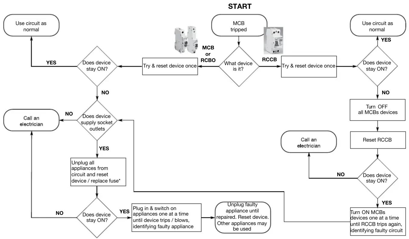
flowchart
graph TD
    A["Use circuit as normal"] -->|YES| B{Does device stay ON?}
    B -->|NO| C{Does device supply socket outlets}
    C -->|YES| D["Unplug all appliances from circuit and reset device / replace fuse*"]
    D -->|NO| E["Call an electrician"]
    E --> F{Does device stay ON?}
    F -->|YES| G["Plug in & switch on appliances one at a time until device trips / blows, identifying faulty appliance"]
    G --> H["Unplug faulty appliance until repaired. Reset device. Other appliances may be used"]
    H --> I["Turn ON MCBs devices one at a time until RCCB trips again, identifying faulty circuit"]
    I -->|NO| J["Call an electrician"]
    J --> K{Does device stay ON?}
    K -->|YES| L["Use circuit as normal"]
    K -->|NO| M["Turn OFF all MCBs devices"]
    M --> N["Reset RCCB"]
    N --> O{Does device stay ON?}
    O -->|YES| P["Use circuit as normal"]
    O -->|NO| Q["Call an electrician"]
    Q --> R{Does device stay ON?}
    R -->|YES| S["MCB tripped"]
    R -->|NO| T["MCB or RCBO"]
    S --> U["Try & reset device once"]
    T --> V["RCCB"]
    U --> W{What device is it?}
    V --> X["Try & reset device once"]
    X --> Y{Does device stay ON?}
    Y -->|YES| Z["Use circuit as normal"]
    Y -->|NO| AA["Turn OFF all MCBs devices"]
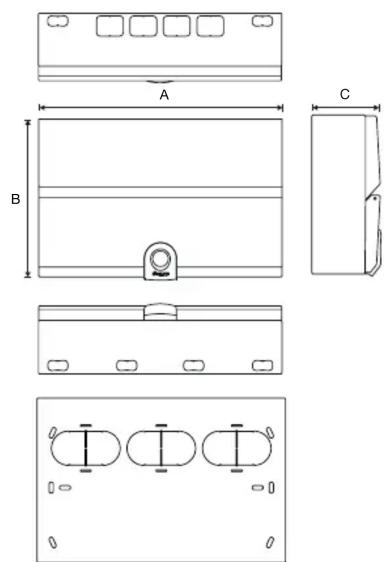
Design 30
| Dimensions(mm) | Enclosure Size | |||||
| 2 3 4 5 6 7 | ||||||
| A 149 221 293 | 364 400 | 472 | ||||
| B | 240 240 | 240 240 | 240 240 | |||
| C | 102.5 | 102.5 | 102.5 | 102.5 | 102.5 | 102.5 |

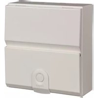

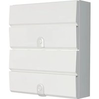

Brand : HAGER
Model : VM202K
Category : Electrical panel