BGA244 - Gas detector SRS - Free user manual and instructions
Find the device manual for free BGA244 SRS in PDF.


| Product Type | Gas Detector (Residual Gas Analyzer) |
| Brand | SRS (Stanford Research Systems) |
| Model | BGA244 |
| Category | Gas Detector / Mass Spectrometer |
| Dimensions (W x H x D) | Approx. 430 x 130 x 330 mm (17 x 5 x 13 inches) |
| Weight | Approx. 10 kg (22 lbs) |
| Power Supply | 100–240 VAC, 50/60 Hz, <100 W |
| Display | Backlit LCD, numeric and graphical data |
| Measurement Principle | Quadrupole mass spectrometry / thermal conductivity |
| Mass Range | 1–200 amu (typical) |
| Minimum Detectable Partial Pressure | 5 × 10⁻¹² Torr (N₂ equivalent) |
| Maximum Operating Pressure | 1 × 10⁻⁴ Torr (for direct sampling; higher with pressure reduction) |
| Filament Type | Yttria-coated iridium or tungsten |
| Main Functions | Residual gas analysis, leak detection, gas composition monitoring, data logging |
| Communication Interfaces | RS-232, RS-485, Ethernet (optional) |
| Analog Output | 0–10 V |
| Maintenance | Regular filament replacement, ion source cleaning, calibration with known gases |
| Safety Precautions | Operate within specified pressure and temperature; follow HV shutdown procedures |
| Spare Parts Available | Filaments, ion source, electron multiplier, replacement sensors |
| Repairability | Field-replaceable modules; factory service available |
| Warranty | 1 year standard |
Frequently Asked Questions - BGA244 SRS
User questions about BGA244 SRS
0 question about this device. Answer the ones you know or ask your own.
Ask a new question about this device
Download the instructions for your Gas detector in PDF format for free! Find your manual BGA244 - SRS and take your electronic device back in hand. On this page are published all the documents necessary for the use of your device. BGA244 by SRS.
USER MANUAL BGA244 SRS
BGA244 Binary Gas Analyzer
User Manual


Stanford Research Systems
Certification
Stanford Research Systems certifies that this product met its published specification at the time of shipment.
Warranty
This Stanford Research Systems product is warranted against defects in materials and workmanship for a period of one (1) year from the date of shipment.
Service
For warranty service or repair, this product must be returned to a Stanford Research Systems authorized service facility. Contact Stanford Research Systems or an authorized representative for a RMA (Return Material Authorization) Number before returning this product for repair. These are available at www.thinksrs.com under Support, Repair/Calibration.
All users returning a BGA244 back to the factory for repair and/or service must submit a correctly completed “Declaration of Contamination of Equipment” form, available as part of the RMA process. The SRS personnel carrying out repair and service of the BGA244 must be informed of the condition of the components prior to any work being performed.
Warning

All returns to SRS must be free of harmful, corrosive, radioactive or toxic materials.
Dedication
In memory of Jim Williams, 1948 - 2011: Legendary Author and Analog Design Guru
Information in this document is subject to change without notice.
Copyright © Stanford Research Systems, Inc., 2016-2018. All rights reserved.
Stanford Research Systems, Inc.
1290-C Reamwood Avenue
Sunnyvale, California 94089
Phone: (408) 744-9040
Fax: (408) 744-9049
Email: info@thinksrs.com
www.thinksrs.com
Printed in the USA
Contents
Contents i
Tables viii
Figures ix
Safety Procedures and Precautions x
Symbols You May Find on SRS Products xii
Specifications xiii
Manual Convention xviii
Unit Conventions and Abbreviations xx
How this Manual is Organized xxi
Chapter 1: Getting Started 1
Binary Gas Analyzers 1
What is a Binary Gas Analyzer? 1
Uses for Binary Gas Analyzers 2
Features and Accessories 3
Display 3
Electrical Connections 3
Accessories 4
Unpacking 8
Quick Start 9
Quick Test 9
Installation and Configuration 10
Chapter 2: Installation Guide 13
Operating Environment 13
Access 14
Installation 15
Gas Fittings 16
BGA244 16
Gas Fitting Adapters 17
BGA244HP 18
Electrical Connections 19
Electrical Noise Precautions 19
Grounding 19
Electrical Connectors 20
Connector Pinouts 20
Terminal Strip Connectors 21
Power 22
Table of Contents ii
Computer Interfaces 24
Analog I/O Connections 26
Event Relays 30
Pressure Transducers 31
Mounting Location 31
Types of Pressure Transducers 31
Chapter 3: Operation Guide 35
BGA244 User Interface 35
Navigation 35
Help Screens 35
Map of Interface Functions 36
Power On 37
Appearance 38
Binary Gas Analyzer 40
Details 42
Gas Purity Analyzer 44
Details 46
Physical Measurements 47
Details 49
Screen Messages 50
Analysis Messages 50
Other Messages 51
LED Blink Codes 53
Controls 54
Limits 54
Scale (Binary & Gas Purity) 55
Pressure (Physical Measurements) 55
Help 55
Event Relay 1 & 2 55
Setup 57
Setup 58
Run|Stop 58
Instrument Mode 58
Selecting Gases 58
REL 61
Pressure 63
Temperature 66
Store|Recall 66
Default Setup 68
Control Panel 72
Display 72
Units 73
Table of Contents iii
Measurement 74
Status 76
Heater 77
Computer I/O 78
Analog I/O 80
Faults 84
Alerts 86
Message Log 88
Self Test 88
Password 90
About the BGA244 90
Hardware Reset 91
User Gases 91
Updating Firmware 91
Chapter 4: Application Guide 93
Gases 93
Gas Requirements 93
Gases that should be used with caution 94
Unusual Gas Properties 94
Condensation 95
Water Vapor in Air 96
Pressure 98
Operating Pressure 98
Pressure Effects in Gases 98
Minimum Operating Pressures 99
Ambient Pressure Variation 100
Operating Conditions 101
Interference 103
Measurements 104
Temperature Variations 104
Evacuating Cell 104
Using Averaging 104
REL to a Reference Gas 105
Binary Gas Analyzer vs Gas Purity Analyzer 107
When to use the Binary Gas Analyzer 107
When to use the Gas Purity Analyzer 107
Converting Molar Fraction vs Mass Fraction 108
Accuracy & Stability 109
Estimated Accuracy 110
Binary Gas Measurement Accuracy 110
Gas Purity Measurement Accuracy 112
Table of Contents iv
Long Term Stability 112
High Purity Use 113
Fittings and tubing 113
Leak Testing 113
Dead Volumes 113
Outgassing 113
Degas 114
User Gases 116
User Gas Parameters 117
Adding a User Gas with BGAMon 118
Adding a User Gas over a Computer Interface 118
Adding Gases 119
Chapter 5: BGAMon 123
Installation 124
Drivers 124
Downloading BGAMon 124
BGAMon Quick Start 125
Using BGAMon 126
Menu Bar 126
System Area 127
Instrument Page 128
Status Bar 128
Instrument Pages 129
Snapshot 129
Analog I/O 130
Pressure 131
Limits 132
Events 132
Strip Chart 133
Gas Selection 138
Faults/Alerts 140
Computer I/O 140
Store / Recall 141
Loading and Saving Configurations 142
Updating Firmware 143
Troubleshooting BGAMon 144
Chapter 6: Remote Programming 145
Introduction 145
Interface Configuration 145
Front-Panel Indicators 145
Transmit and Receive Buffers 145
Table of Contents v
| Break Signal 146USB 146RS-232RS-422 | 146147 |
| Command Syntax 148Parameter Conventions 148Numeric Conventions 149Measurement Errors 149Missing Power Supplies 149 | |
| Abridged Index of Commands | 150 |
| Detailed Command List | 154 |
| Common IEEE-488.2 Commands | 154 |
| Instrument Status Commands | 157 |
| Interface Commands | 164 |
| Measurement and Related Commands | 165 |
| Configuration Commands | 171 |
| Analog I/O Commands | 178 |
| Miscellaneous Commands | 184 |
| Status Byte Definitions | 188 |
| Serial Poll Status Byte 189 | |
| Standard Event Status Register | 189 |
| Instrument Status Register Model | 189 |
| Event Status Register | 192 |
| Error Codes | 193 |
| Execution Errors | 193 |
| Query Errors | 194 |
| Parsing or Command Errors | 194 |
| Communication Errors | 195 |
| Other Errors | 195 |
| Using the USB Drivers | 196 |
| Chapter 7: Service | 197 |
| Troubleshooting | 197 |
| Power On | 197 |
| Self Tests | 198 |
| System Faults | 199 |
| Alerts | 200 |
| Screen Messages | 201 |
| Factory Safe Mode | 203 |
| Locked 204 | |
| Store and Recall Failure 204 | |
| Touchscreen Problems | 205 |
| Hardware Reset | 205 |
Table of Contents vi
Installing BGA-M 206
Maintenance 207
Replacing Gas Fittings 207
Replacing Gas Fittings for the BGA244E 208
Terminal Strips 209
Cleaning 209
Calibration 210
Performance Verification 210
Self Test 210
Analog I/O Accuracy 211
Measurement Accuracy 215
Chapter 8: Circuit Description 217
Overview 217
Block Diagram 217
Detailed Circuit Description 219
Main Circuit Board 219
Microphone Board 225
Speaker Board 229
Industrial Board 230
Control Board 231
Appendix A: Gas Table 235
Factory Gas Table 235
Gas Table Properties 246
References 255
Appendix B: BGA244E 257
Operation 257
Environment 257
Access 258
Unpacking 259
Quick Start 259
Installation 260
Mounting 260
Gas Fittings 261
Conduit 262
Electrical 262
Appendix C: Mechanical Drawings 265
Appendix D: Declaration of Contamination 269
Appendix E: Installing USB Drivers 271
Appendix F: Parts List 273
Appendix G: Schematics 281
Appendix H: Revisions 297
Tables
Table 1: Gas Fitting Adapters .... 5
Table 2: Gas Fitting Adapters ...... 17
Table 3: C3: RS-232....20
Table 4: C4: RS-422....20
Table 5: C5: +24V....21
Table 6: C6: Measure Out....21
Table 7: C7: Analog I/O....21
Table 8: C8: Relay Contacts....21
Table 9: Active Parameters 68
Table 10: Inactive Parameters....70
Table 11: External Power Supply Faults 84
Table 12: System Faults....85
Table 13: Analog I/O Alerts 86
Table 14: Temperature Alerts 87
Table 15: General Alerts....87
Table 16: Self Tests....89
Table 17: Recommended Minimum Operating Pressures for Pure Gases.... 100
Table 18: Heater Settling Time.... 101
Table 19: Response Time 101
Table 20: Zero Flow Transient Settling Time.... 102
Table 21: Transient Settling Time for Different Flow Rates.... 102
Table 22: Command Parameter Conventions....149
Table 23: Power Supply Fault Description 199
Table 24: System Fault Description.... 199
Table 25: Temperature Alert Description 200
Table 26: Power Supply Alert Description.... 200
Table 27: Analog I/O Alert Description 201
Table 28: Measure Out Test Limits 212
Table 29: Analog I/O Test Limits 214
Table 30: Pressure vs Altitude....215
Table 31: Auxiliary ADC Voltages 222
Table 32: Power Supply Test Points 224
Table 33: Control Board Relays.... 232
Table 34: Control Board Relay Function.... 233
Table 35: Factory Gas Table 235
Table 36: Gas Table Properties 247
Table 37: C9: RS-232 Connector for BGA244E 263
Figures
Figure 1: BGA244....6
Figure 2: BGA244 Display 6
Figure 3: BGA-M Metal Cover Accessory....7
Figure 4: RS-422 Signal Path....25
Figure 5: Voltage Output 26
Figure 6: Current Output 27
Figure 7: Voltage Input 27
Figure 8: Current Input....28
Figure 9: Current Input w/ Loop Power (suitable device)....28
Figure 10: Current Input w/ Loop Power (unsuitable device)....29
Figure 11: Event Relay Contacts....30
Figure 12: Map of User Interface Functions....36
Figure 13: BGA244 Home Page 38
Figure 14: Binary Gas Analyzer Home Page .... 41
Figure 15: Gas Purity Analyzer Home Page 45
Figure 16: Physical Measurements Home Page 48
Figure 17: Speed of Sound vs Pressure in SF6....98
Figure 18: Gas Concentration with and without Averaging for Argon and Air 105
Figure 19: BGAMon Snapshot Screen.... 125
Figure 20: BGAMon Layout....126
Figure 21: Snapshot Page 129
Figure 22: Analog I/O Page....130
Figure 23: Pressure Page 131
Figure 24: Limits Page....132
Figure 25: Events Page 132
Figure 26: Strip Chart Page....133
Figure 27: Print Preview Window....136
Figure 28: Export Window....137
Figure 29: Gas Selection Page ...... 138
Figure 30: Fault/Alert Page....140
Figure 31: Computer I/O Page.... 140
Figure 32: Store/Recall Page 141
Figure 33: Setup for Measure Out Voltage Test....211
Figure 34: Setup for Measure Out Current Test....211
Figure 35: Setup for Analog I/O Voltage Test....213
Figure 36: Setup for Analog I/O Current Test....213
Figure 37: BGA244 Mechanical Drawing....266
Figure 38: BGA244E Mechanical Drawing (No Mounting Flanges) 267
Figure 39: BGA244E Mechanical Drawing (with Mounting Flanges)....268
Safety Procedures and Precautions
Observe the following general safety precautions during all phases of operation of this instrument. Failure to comply with these precautions or with other specific warnings elsewhere in this manual violates the safety standards of intended use of this instrument and may impair the protection provided by the equipment. Stanford Research Systems, Inc. assumes no liability for the customer's failure to comply with these requirements.
DO NOT SUBSTITUTE PARTS OR MODIFY THE INSTRUMENT
Do not install substitute parts or perform any unauthorized modification to the instrument. Return the instrument to Stanford Research Systems or an authorized representative for service and repair to ensure all safety features are maintained.
SERVICE BY QUALIFIED PERSONNEL ONLY
Operating personnel should not attempt any component replacement or internal adjustments. Any service should be performed by qualified service personnel only.
USE CAUTION WHEN OPERATING WITH HAZARDOUS MATERIALS
If hazardous materials are used, users must take responsibility to observe proper safety precautions, completely purge the instrument when necessary, and ensure the material used is compatible with materials in this product, including any sealing materials.
PURGE THE INSTRUMENT
After installing the unit or before removing it from a system, purge the unit completely with a clean dry gas to eliminate all traces of the previously used flow material.
USE PROPER PROCEDURES WHEN PURGING
Purge the instrument under a ventilation hood. Wear gloves for protection during this procedure.
EXPLOSIVE ENVIRONMENT WARNING
The BGA244 is not ATEX rated. Under normal operating conditions the BGA244 cannot ignite the gas being analyzed. However, if the instrument is used with flammable or explosive gas mixtures, SRS recommends the use of flame arrestors on both gas ports.
The BGA244 gas cavity's proof pressure (2,500 psia) is sufficient to contain the detonation of an explosive gas mixture of up to 30 psia. The instrument will likely be damaged by such an event.
USE PROPER FITTINGS AND TIGHTENING PROCEDURES
All instrument fittings must be consistent with instrument specifications and compatible with the intended use of the instrument. Assemble and tighten fittings according to manufacturer's directions.
CHECK FOR LEAK-TIGHT FITTINGS
Carefully check all connections to ensure leak tight installation.
OPERATE AT SAFE INLET PRESSURES
Never operate at pressures higher than the maximum operating pressure (refer to the product specifications for the maximum pressure).
INSTALL A SUITABLE BURST DISK
When operating from a pressurized gas source that may exceed the cavity proof pressure (2500 psia), install a suitable burst disk to prevent system explosion should the system pressure rise.
KEEP THE UNIT FREE OF CONTAMINATION
Do not allow contaminants to enter the unit before or during use. Contamination such as dust, dirt, lint, glass chips and metal chips may permanently damage the unit or contaminate the process.
ALLOW PROPER WARM UP TIME
The unit may not meet all specifications unless sufficient time is allowed for the unit to stabilize at the designed operating temperature. Do not REL or calibrate the unit until the warmup is complete.
GROUNDING
Proper operation of this instrument requires that it be connected to earth ground. If the power source does not provide the required grounding, you should add a protective ground to the device.
COVERS
Do not operate the unit with the instrument covers removed.
RETURNS
All returns to SRS must be free of harmful, corrosive, radioactive or toxic materials.
Users returning a BGA244 back to the factory for repair and/or service must submit a correctly completed “Declaration of Contamination of Equipment” form, available as part of the RMA process. The SRS personnel carrying out repair and service of the BGA244 must be informed of the condition of the components prior to any work being performed. See Appendix D: Declaration of Contamination for information required for the “Declaration of Contamination of Equipment” form.
Symbols You May Find on SRS Products
| Symbol Description | |
 | Alternating Current |
 | Caution – risk of electrical shock |
 | Frame or Chassis terminal |
 | Caution – refer to accompanying document |
 | Earth (ground) terminal |
 | Battery |
 | Fuse |
 | Power On |
 | Power Off |
 | Power Standby |
Specifications
Operational
Instrument Modes Binary Gas Analyzer: Concentration in mole or mass fraction
Gas Purity Analyzer: Deviation in speed of sound from ideal speed of sound / ideal speed of sound ΔW / W
Physical Measurements: Measured Speed of Sound, Normalized Speed of Sound, temperature, and pressure
Operating Pressure 0 to 150 psia (1000 kPa)
Operating Temperature -20 °C to +70 °C
Flow Rate 0 to 5000 sccm
Gas Species \~500 gases supported in Factory Gas Table, Users can add gases to the User Gas Table
Response Time 9 seconds to 90%
for a step change 18 seconds to 99%, (2000 sccm flow rate) 27 seconds to 99.9%
Recommended Min Pressure Gas Species Dependent (examples for pure gases)
| H | 2 | 10 psia (69 kPa) |
| He | 10 psia (69 kPa) | |
| CH | 4 | 5 psia (34 kPa) |
| N | 2 | 3 psia (21 kPa) |
| Ar | 3 psia (21 kPa) | |
| CO | 2 | 12 psia (83 kPa) |
| SF | 6 | 2 psia (14 kPa) |
Measurement
Measurement Technique The Speed of Sound of the gas is measured using a cylindrical resonator using acoustic transducers. The gas temperature is measured using thermistors inside the resonant cavity.
The Normalized Speed of Sound and Gas Concentration is calculated based on the cylindrical resonator characteristics and the thermodynamic properties of the gases.
Reading Rate \~4.4 Hz
Averaging None, or 2 to 100 samples averaged
| Temperature Measurement | Accuracy: | ± 0.1 °C |
| Resolution: | 0.001 °C | |
| Aging: | ± 0.001 °C/year |
| Speed of Sound Measurement | Range: | 100 to 1500 m/s |
| Resolution: | 0.001 m/s | |
| Aging: | ± 5 ppm/year | |
| Accuracy: | ± 0.05% (14.7 psia Argon at 200 sccm) |
Concentration Measurement 1 Range: 0 – 100%, 0 – 1,000,000 ppm or 0 – 1.0 frac
Resolution: 1 ppm
Stability: typically 10 ppm
Accuracy: typically 100 – 1000 ppm
1 All concentration specifications depend on the gas species being measured. See Accuracy in the Application Guide for more information.
Heater (requires 24V)
| Set Temperature | 0 °C to 70 °C |
| Current Limit | 0.05 to 2.5 A |
| Settling Time to final temperature | 16 minutes for 25 °C to 50 °C temperature step, with 2 A max current |
| Protection | Over temperature and Over Current Protected |
Analog I/O (requires 24V)
Outputs
| Function | Measure Out: | Gas Ratio, Gas Purity or Normalized Speed of Sound |
| Output 1, 2: | Speed of Sound, Normalized Speed of Sound, Temperature, Pressure or User Value | |
| Range | Voltage | 0 to 5 V, 0 to 10 V |
| Current | 4 to 20 mA | |
| Resolution | Voltage (5V range) | 0.1 mV |
| Voltage (10V range) | 0.2 mV | |
| Current | 0.4 μA | |
| Accuracy 1 | Voltage 2 | ±0.1 % + 1 mV |
| Current | ±0.1 % + 10 μA |
1 Output accuracy specifications are for User values. For Measure Out or Linked output values the accuracy is determined by the measured parameter being output.
2 Voltage accuracy specifications apply for V > 0.4% of the Range
Max Output Current (Voltage Out) 20 mA
Max Load Resistor (Current Out) 840 Ω
Inputs
| Function | Input 1, 2 | Pressure Sensor or User Value |
| Range | Voltage | 0 to 10 V |
| Current | 4 to 20 mA, 4 to 20 mA with Loop Power | |
| Resolution | Voltage | 1 μV |
| Current 1 nA | ||
| Accuracy | Voltage | ±0.1 % + 1 mV |
| Current | ±0.1 % + 10 μA |
Input Impedance Voltage 10 MΩ
Current 201 Ω
Absolute Maximum Voltage 24 V
Current 25 mA
Loop Power Voltage Range 6 to 19 V
Resolution 0.1 V
Max Current 50 mA
Event Relay (requires 24V)
Function 2 independently configurable DPDT relays that can be set to switch on a combination of events
Events Measurement limits, pressure limits, temperature limits, "No Signal" and System Fault
Relay Contact Rating
Max Switching Power 30 W, 62.5 VA
Max Switching Voltage 220 V DC , 250 V AC
Max Switching Current 1 A
Max Carrying Current 2 A
Computer I/O
RS-232
Format No parity, 8 bits, 1 stop bit, CTS/RTS flow control
Baud Rate 2400 - 115.2k
Max Cable Length >100 meters for lower baud rates
USB
Connector USB Type B
Format WHQL high speed USB2.0
Drivers available Virtual COM Port (VCP) and Direct Drivers (USB drivers + DLL)
OS Support
Microsoft Windows7, 8 (32, 64 bit), Windows Vista, XP (32, 64 bit),
Windows XP Embedded, Windows CE 4.2, 5.0 & 6.0
Other Mac OS-X, Linux 2.6 & greater, Android
RS-422 (requires 24V)
Format 4 wire, point-to-point, non-multidrop,
no parity, 8 bits, 1 stop bit, no flow control
Baud Rate 2400 - 115.2k
Max Cable Length >1000 meters for lower baud rates
Power
USB
Connector USB Type B
Voltage +5 V DC , +/- 0.25 V *
Current 0.35 A continuous, 0.45A max on startup
* The USB voltage must be >4.75V at the BGA244. Be sure to use a device that can supply enough current and a large enough wire gauge cable that can support this voltage. See Power in the Installation Guide for details.
Note that the USB current goes to 0 mA when +24V is connected.
+24 V
Connector 3.1 mm barrel jack, 2 wire terminal strip
Voltage +24 V DC, +/- 1 V
Ripple <240 mV p-p
Current
No Analog I/O, Heater 0.2 A
Max 2.7 A
Environment
Cavity Proof Pressure 2500 psi (17 MPa)
Operating Temperature -20°C to 70°C
Storage Temperature 80 °C max
Humidity <90 % relative humidity, non-condensing
Altitude ≤ 4000 m (for applications above this altitude, contact SRS)
Pollution Degree Category 2: (EN61010-1; only non-conductive pollution)
Inbound Helium Leak Rate: 1 × 10⁻⁸ sccs (BGA244HP only)
Physical
BGA244, BGA244 HP
| Front Panel | Color TFT-LCD w/ touchscreenPower, Communication and Error LED Indicators |
| Dimensions | 5.5" x 4.5" x 3.25" (WHD) |
| Weight | 7 lbs (3.2 kg) |
| Swept Volume | 130 cc (Acoustic Chamber Volume) |
Gas Fittings
BGA244 1/8 "-27 female NPT
BGA244HP ¼"male welded VCR
Wetted Materials
BGA244, BGA244E Electro polished 304 stainless steel, OFHC copper gaskets, nickel plated/immersion gold copper traces on 0.001" Kapton film, vented 316 stainless steel screws, 316 stainless steel NPT fittings, glass and nickel plated Dumet wire.
Loctite 565 thread sealant is used to seal the NPT fittings.
BGA244HP Electro polished 304 stainless steel, gold plated OFHC copper gaskets, nickel plated/immersion gold copper traces on 0.001" Kapton film, vented 316 stainless steel screws, 316 stainless steel male VCR fittings, glass, and nickel plated Dumet wire.
The VCR fittings are welded in place.
BGA244E
When properly installed, the BGA244E (with Environmental Enclosure) will meet the following NEMA / UL-50 standards. See Appendix B (Environmental Enclosure) for installation instructions. All other specifications match the BGA244 unless otherwise noted.
Environmental Enclosure NEMA 6 (with catch latched)
Ratings: NEMA 6L (with screws installed)
IP66, UL Type 4X, UL-50
Gas Fittings 1/8 "-27 female NPT
Electrical 3/4 " Flexible, Non-Metallic Conduit (FNMC)
Dimensions 10" x 11" x 5.5" (WHD)
Weight 11 lbs. (5 kg)
Manual Convention
The BGA244 is operated thru a multilevel graphical user interface. The following conventions are used in the manual to describe different functions of the interface.
[Key]
This key is either a navigation key that will take you to a different display or a direct action key that will perform the action listed on the key.
![SRS BGA244 - [Key] - 1](/content/2026/06/1372977/images/3a38f0b705aedbe858aecde96514e80029ef18ef13d3930fcdd5538b58b1f59a.jpg)
[On|Off]
This is an on/off or enable/disable key. Press the desired side of the key to activate that function.
This indicates On or Enabled
This indicates Off or Disabled.
![SRS BGA244 - [On|Off] - 1](/content/2026/06/1372977/images/9cf3389c0f963ecc3c0e9b531169a0a1db32b9730d1eb6d7d728fb75bf5b4dbb.jpg)
This indicates that a value needs to be entered where "Entry" is the name of the parameter. Pressing the key will open up the alphanumeric keypad for data entry.
![SRS BGA244 - [On|Off] - 1](/content/2026/06/1372977/images/5927ba0c7778ff834303b1d56f84ed3b2af0fb375273d7032f8038d00f3a96bf.jpg)
If the entered value is out of range, it will be ignored and an "Invalid Entry" prompt will appear indicating the maximum allowable value.
[ESC]
This key on the alpha-numeric keypad allows you to exit without entering a new value.
![SRS BGA244 - [ESC] - 1](/content/2026/06/1372977/images/39a644028b020f6c62e556a614f79560a5d126f5560d755e42ee46ead73f3686.jpg)
This indicates that a value needs to be selected from a list where "Entry ↓" is the name of the list. Pressing the key will open a drop
![SRS BGA244 - [ESC] - 1](/content/2026/06/1372977/images/14a00428870115628d2debb36912a1cd791ddc9312d2a957c4b566ebfb763bfa.jpg)
list of possible selections. [Press] the desired selections to choose it. The current selection is normally highlighted in yellow.
○ Choice
This indicates a “radio button” that is used to select one of a number of possible choices. Press the circle to select that choice and de-select all other choices.

□ Choice
This indicates a check box that is used to enable a choice. Unlike Radio Buttons, you can select any or all of check boxes as needed.
(Home/Here/Over_There)
This denotes a location in the user interface hierarchy. To reach (Home/Here/Over_There) from the Home Page you would press [Here], followed by [Over_There].
[Home]
This returns you to the BGA244 Home Page. Note that the Home display has different appearances depending on the Analyzer Mode selected.
HOME
[←] or [Back]
This returns up one level from the display you are currently on.
←
[Help]
This takes you to the Help screen for that page. This page will have information about the settings and displayed parameters. [Page ↑] and [Page ↓] are active if the Help screen is more than one page long.
HELP
Note: The touch screen on the BGA244 must be actually be pressed to activate functions. This is normally indicated by a key click or beep. Hovering over the button like you do on a cell phone or tablet won't activate the control.
Throughout the manual, text in Italics refers to another section of the manual.
Unit Conventions and Abbreviations
Normal Temperature and Pressure (NTP)
Several different conventions are used to normalize measurements to a fixed temperature and pressure. The BGA244 uses “Normal Temperature and Pressure” (NTP) for all of its normalized readings. This is defined as the following:
■ Temperature: 20.00°C, 293.15°K or 68.00°F
■ Pressure (absolute): 1 atm, 101.325 kPa or 14.696 psia
Flow
There are a few abbreviations used to describe flow rate.
SCCM: standard cc (ml) per minute
SCCS: standard cc (ml) per second
Speed of Sound
The Speed of Sound is occasionally abbreviated as "SOS" in the manual.
Normalized Speed of Sound
The speed of sound in a gas varies as a function of several environmental parameters. The dominant effects are caused by pressure and temperature. An additional effect is caused by the frequency at which the speed of sound is measured. The frequency dependent effect is due to vibrational population relaxation effects in the gas molecules. This effect is specific to the particular gas being measured.
The BGA244 normalizes the speed of sound to NTP at the measured frequency.
The Normalized Speed of Sound is occasionally abbreviated as "NSOS" in the manual.
Pressure
Pressure can be referred to in either absolute or gauge pressure units. Absolute pressure units are relative to vacuum, while gauge pressure units are relative to the ambient pressure on the outside of the gauge.
When using gauge units it is important to enter the ambient pressure, as the BGA244 uses absolute pressure in its calculations.
How this Manual is Organized
This manual provides instructions on how to install and operate a BGA244 Binary Gas Analyzer.
Before installing your BGA244 in a system and/or operating it, carefully read and familiarize yourself with all precautionary notes in the Safety and Installation sections at the beginning of this manual. In addition, observe and obey all WARNING and CAUTION notes provided throughout the manual.
Chapter 1: Getting Started
Describes the BGA244 including measurements and applications and a quick start guide
Chapter 2: Installation Guide
Explains the environmental requirements and describes how to install the BGA244 in your system
Chapter 3: Operation Guide
Describes how to configure and operate the instrument and explains all of its functionality in detail
Chapter 4: Applications Guide
Describes how to optimize the BGA244 for the best performance in your application
Chapter 5: BGAMon
Describes how to configure and control the BGA244 using the BGAMon Windows software
Chapter 6: Remote Programming
Describes how to control the BGA244 using the computer interfaces
Chapter 7: Service
Troubleshooting, Maintenance and Calibration of the BGA244
Chapter 8: Circuit Description
Description of the BGA244s electronic circuitry
Appendix A: Gas Table
A list of all supported gases in the Factory Gas Table, plus a description of the data contained in the Gas Table
Appendix B: BGA244E
Description of the BGA244E, a NEMA enclosed version of the BGA244
Appendix C: Mechanical Drawings
Mechanical drawings and mounting locations for the BGA244 and its derivatives
Appendix D: Declaration of Contamination
Sample of the Declaration of Contamination form
Appendix E: Installing the USB Drivers
Instruction on manually installing the USB Drivers
Appendix F: Parts List
Parts list of the BGA244 and derivatives
Appendix G: Schematics
Electrical Schematics for the BGA244
Appendix H: Revisions
List of manual revisions
...
Trademarks
The trademarks of the products mentioned in this manual are held by the companies or organizations that produce them.
CAS Registry Number is a Registered Trademark of the American Chemical Society.
VRC, VCO and Swagelok are Registered Trademarks of Swagelok, Company.
Windows, Windows XP, Windows 7, Windows 8 and Windows 10 are Registered Trademarks of Microsoft Corporation.
Combicon and Phoenix Contact are trademarks of Phoenix Contact.
FTDI is a Trademark of Future Technology Devices International Ltd.
McMaster and McMaster-Carr are registered Trademarks of McMaster-Carr.
All other brand and product names are trademarks or registered trademarks of their respective companies.
Chapter 1: Getting Started
Binary Gas Analyzers
What is a Binary Gas Analyzer?
A Binary Gas Analyzer (or BGA) measures the ratio of two gases based on physical properties of the gases. Other instruments do this by measuring the thermal conductivity of the gas mixture or by measuring the speed of sound in the gas using a time-of-flight technique. Both the thermal conductivity and speed of sound of a gas vary inversely with their molar mass (along with several other gas properties). So the ratio of two gases can be calculated if you know the properties of the two gases and the thermal conductivity or speed of sound in the mixture.
A different method of measuring the speed of sound uses a resonant acoustic cell. Measuring the resonant frequencies within the cell and knowledge of the cell's geometry allows the speed of sound to be accurately calculated. This information combined with knowledge of the physical properties of the gases allows you to accurately determine the ratio of the two gases.
The BGA244 works by injecting a wideband acoustic signal into a gas cell using a speaker. The resonant modes of the cell are excited, producing large amplitudes at the resonant frequencies. This signal is measured using a sensitive, wideband microphone. Advanced signal processing extracts the frequencies of the resonant peaks and from them, the speed of sound.
Combining the speed of sound, temperature and pressure with a detailed list of about 500 different gases allow the BGA244 to make ratio measurements with a typical accuracy of better than 0.1%
This technique isn't just reserved for gases of a single species. Blended gases can also be measured, as long as physical data is available for each gas blend. The best known blended gas is air, made up of nitrogen, oxygen, argon and carbon dioxide. There are many other blended gases that can be used in the BGA244.
Most binary gas analyzers are factory configured to support a handful of gases, or only a single mixture over a limited range. In contrast, the BGA244 comes configured with data on nearly 500 gases that are characterized over a wide range of concentrations. This gas information is easily selected from the front panel or can be configured remotely, allowing over 50,000 different mixtures to be measured.
In addition to binary gas ratio measurements, the BGA244 can report purity of a gas expressed as the ratio of the measured speed of sound to the expected speed of sound. To support other research goals, measurements of the speed of sound, temperature and pressure can be reported directly.
Uses for Binary Gas Analyzers
Binary gas analyzers are used in a wide range of applications. They are often used in applications where no dedicated sensors exist for a gas or for indirectly controlled mixtures in a process.
A few typical applications are:
- Leak Detection
■ Semiconductor Processing
■ Food Processing
■ Quality Control
■ Environmental Monitoring
■ Purge Gas Analysis
■ Shielding or Blanketing Gas Monitoring
■ Generator Cooling Gas Monitoring
■ Heat Treating Gas Monitoring
■ Gas purity monitoring
■ Measuring Helium – Deuterium ratio
■ Measuring He-3 / He-4 ratio
■ Helium Recovery Systems
Features and Accessories
The BGA244 consists of a compact package which includes the resonant cell, acoustic transducers, sensitive electronics and advanced signal processing. It can be powered over USB or +24 V and can interface to external devices by computer interface or analog signals and features a touch screen LCD to configure and monitor measurements.
There are three models in the BGA244 series: the standard BGA244, the BGA244HP (high purity) and the BGA244E (enclosure). All models share the same acoustic resonant cell, transducers, signal processing and computer interfaces.
BGA244
The standard BGA244 is designed to operate in most common operating environments. It comes with 1/8 "-27 female NPT fittings. There are several different accessories available. These include a number of different gas fitting adapters, a 24 V DC power supply and protective covers for the display.
BGA244HP
The BGA244HP (high purity) is designed to operate in high purity or corrosive environments. It comes with welded-in-place 1/4 " male VCR fittings in place of the female NPT fittings and is Helium leak checked. The BGA244HP operates the same as the standard BGA244. All accessories except the gas fitting adapters are available for the BGA244HP.
BGA244E
The BGA244E packages the standard BGA244 in a NEMA Type 6/6P enclosure for use in exposed locations. It comes with 1/8'' -27 female NPT fittings. The BGA244E operates the same as the standard BGA244. All accessories are available for the BGA244E. See Appendix B for specific information on the BGA244E.
Display
The BGA244 includes a color TFT-LCD display with touchscreen. This can be used to configure the unit and display results. (See Figure 2, page 6)
Electrical Connections
The electrical connections and indicators are located on the front of the BGA244. See Figure 1 (page 6) for the connector locations.
All models of the BGA244 can be powered by either 24 VDC or USB power. Several features require 24 VDC to operate including the analog inputs & outputs, heaters, event relays and the RS-422 interface. However the core functionality of the BGA244 will operate using USB power.
USB power can be provided by a computer, a powered USB hub or a USB charger. Be sure to use an appropriate USB cable when powering the BGA244 over USB. The cable that is included with the BGA244 is suitable. See Power (page 22) for information on suitable USB cables. 24 V DC can be provided via a 3mm barrel plug or on a terminal strip.
All instrument functions can be controlled over the USB, RS-232 or RS-422 computer interfaces. There are 3 analog outputs, 2 analog inputs and 2 configurable event relays to interface to external devices.
There are three LEDs that indicate the status of the BGA244.
| Name | Function |
| Power (green) | Shows that power is appliedFlashes for power fault codes |
| Comm (green)(Communication) | Flashes when computer interface is active |
| Error (red) | Flashes for communication errorRepetitive blink for various no signal errors.Constant on for “System Fault” |
Accessories
There are several accessories available for the BGA244.
+24V Power Supply (BGA-24)
Accessory BGA-24 is a 50W universal input power supply that provides +24 V DC at 2.5 A.
Shield (BGA-S)
Accessory BGA-S is an Acrylic shield used to protect the BGA244 Display. This cover is not needed for units using accessory BGA-M.
Note that the display touch screen will not operate through the Acrylic shield. It is necessary to first remove the shield before using the touch screen. Replace the Acrylic shield when you are done using the touch screen.
Metal Cover (BGA-M)
Accessory BGA-M is a rugged solid metal cover that can replace the color TFT display for applications where the display is not wanted (Figure 3, page 7). See Installing BGA-M (page 206) for information on installing the cover.
Units should either be configured prior to installing the metal cover or configured over one of the computer interfaces. The simplest way to configure the BGA244 over the computer interface is using the BGAMon program provided by SRS. See Chapter 5: BGAMon (page 123) for more information. The other configuration option is user written code. See Chapter 6: Remote Programming (page 145) for more information.
Gas Fitting Adapters
The following fitting adapters are available to interface the BGA244 to different gas fittings. These adapters connect to the 1/8 ”-27 female NPT fittings of the BGA244. See Chapter 2: Installation Guide (page 17) for more details on using the different gas fitting adapters.
TABLE 1: GAS FITTING ADAPTERS
| Accessory | Gas Fitting Adapter |
| SS2A | 1/8'' -27 male NPT to 1/8'' -27 female NPT |
| SS4RA2 | 1/8'' -27 male NPT to 1/4'' -18 female NPT |
| SS4VCR12 | 1/8'' -27 male NPT to 1/4'' male VCR |
| SS4VCO12 | 1/8'' -27 male NPT to 1/4'' male VCO Body |
| SS4HC12 | 1/8'' -27 male NPT to 1/4'' hose barb ( 1/4'' ID hose) |
| SS40012 | 1/8'' -27 male NPT to 1/4'' compression fitting |
| SS6MO12 | 1/8'' -27 male NPT to 6mm compression fitting |
| 5482K119 | 1/8'' -27 male NPT to 1/4'' , 37° flared AN tube, male, 7/16'' - 20 TPI |
| 4822T76 | 1/8'' -27 male NPT to 1/8'' BSPP female, 1/8'' -28 TPI |
| 4092K26 | 1/8'' -27 male NPT to 1/8'' BSPT female, 1/8'' -28 TPI |

FIGURE 1: BGA244
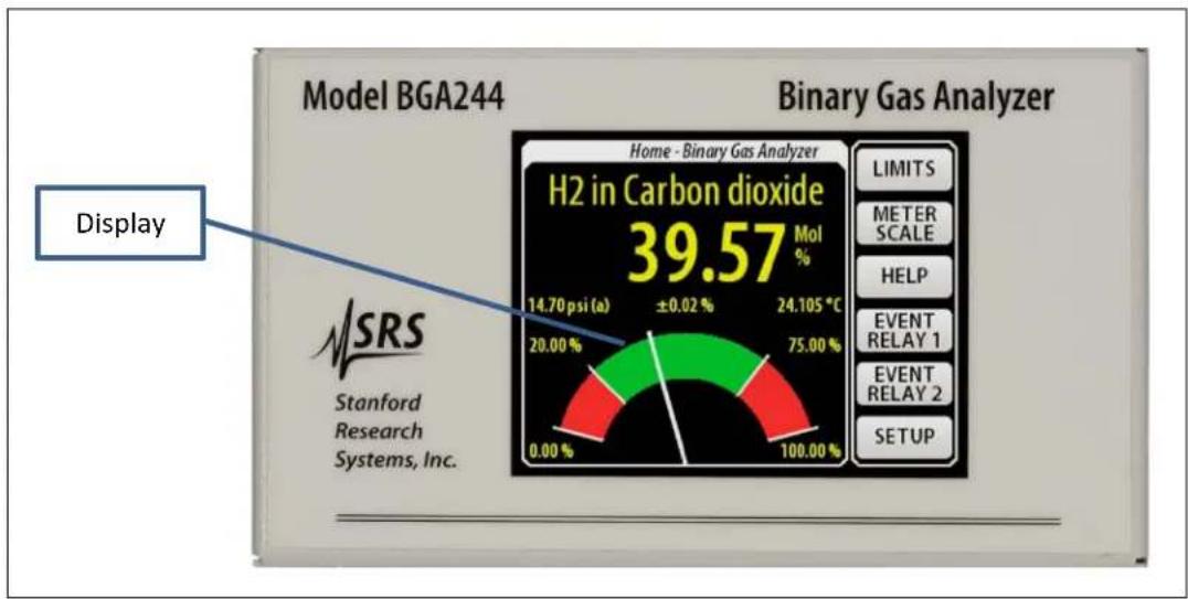
FIGURE 2: BGA244 DISPLAY

FIGURE 3: BGA-M METAL COVER ACCESSORY
Unpacking
Before You Open the Box
Do not remove the gas port caps until just prior to connecting the unit to your gas manifold to reduce the chance of contamination of the cell.
Read the Chapter 2: Installation Guide prior to installing the BGA244 into your system.
Read the Chapter 3: Operations Guide and Chapter 4: Applications Guide prior to operating the BGA244.
Inspect all components of the SRS BGA244 upon unpacking. Report any damage to Stanford Research Systems immediately. Compare the contents of the shipping container to the list below and report any discrepancies.
See www.thinksrs.com/downloads/PDFs/Manuals/BGA244m.pdf for the complete BGA244 User's Manual.
See Appendix B for information specific to the BGA244E.
What is included with the BGA244
- One BGA244
- One 6' (1.8 m) USB cable
- One Quick Start Guide
Accessories (if ordered)
- BGA-24 +24 VDC Power Supply
- BGA-S Acrylic shield for the LCD display
- BGA-M Metal cover to replace display
- Adapters Gas fitting adapters
What is included with the BGA244HP
- BGA244HP
- One 6' (1.8 m) USB cable
- One Quick Start Guide
Accessories (if ordered)
- BGA-24 +24 VDC Power Supply
- BGA-S Acrylic shield for the LCD display
- BGA-M Metal cover to replace display
Quick Start
This guide is intended to help users get started making measurements with the BGA244 or BGA244HP. If the BGA244 has accessory BGA-M (metal cover) in place of the display it is recommended to use the BGAMon software to configure the unit and monitor the results. Refer to Chapter 5: BGAMon for details.
Quick Test
Connect power using either USB power or +24 V DC . Make certain that the USB device and cable are sufficient to power the device if using USB power. See Power (page 22) for more information. If you are planning on operating with both USB and +24 V DC connected, first connect +24 V DC , wait until Self Test has completed and then connect the USB cable.
When power is first applied, a power-on splash screen will appear. After a few seconds the "About" information page will appear. This displays the unit serial number, firmware version, calibration date and hardware version.

After about 15 seconds the Gas Purity Analyzer Home page will appear. Assuming the unit has come from the factory and the gas port caps haven't been removed, it should display < 0.1% deviation reading for Argon.

Disconnect power before continuing with the following steps.
Installation and Configuration
Plan your installation, including mounting and gas tubing connections. Depending on your application, this can be as simple as setting the BGA244 on a bench and connecting flexible tubing or may involve hard mounting the unit and forming metal tubing. Be sure to clean out gas lines prior to connecting them to the BGA244 to avoid contamination. Refer to Chapter 2: Installation Guide if you have any questions regarding these procedures as improper installation can damage the unit.
- Mount the BGA244 as appropriate to your application.
- Connect the gas tubing to the gas ports following the appropriate procedure for the specific gas fittings. Either gas port can be used for input or output.
- Connect either USB power or +24 VDC . If using USB power, be certain that the USB device and cable are sufficient to power the device. Refer to Power (page 22) for more information. The splash screen and “About” page should appear as described in Quick Test.
- Configure the BGA244. Note that it may be easier to configure the unit prior to installing it into your system, especially if access is restricted. See Chapter 3: Operation Guide for more information on each of the following steps.
a. Set the Instrument Mode: [HOME] [SETUP] [INSTRUMENT MODE ↓].
There are 3 choices: Binary Gas Analyzer, Gas Purity Analyzer or Physical Measurements.
b. Select the Gases: [HOME] [SETUP] [SELECT GAS]. Set the Primary Gas and Secondary Gas (note that a Secondary Gas is not required for the Gas Purity Mode). Press [SELECT GAS] to open the gas selection window. Type the first few characters of its name, formula or CAS number, then press [ENTER] to open a list of gases that match that string. Select the desired gas from that list.
c. Configure the Pressure: [HOME] [SETUP] [PRESSURE]. Press [ENTER USER PRESSURE] to open the User pressure window. This is simplest way to enter the pressure. See Pressure (page Pressure63) for information on different methods of entering the operating pressure into the BGA244.
d. Set the Meter Scale and Limits: [HOME] [METER SCALE] and [HOME] [LIMITS] appropriately. (For the Binary Gas and Gas Purity Analyzers only).
- Flow gas through the system. The BGA244 should display the selected gases and concentration, purity or physical measurements of the gas.
Windows Drivers for the BGA244
If the BGA244 is connected to the USB port of a computer running Microsoft Windows, you may be prompted with a "New Hardware Found" message and an invitation to search for the USB Driver. There are two USB drivers for the device (VCP and D2XX drivers). Depending on the version and configuration, Windows may either automatically install the drivers or prompt you to search for them. Allow it to install the drivers if you plan to configure or control the BGA244 using this computer. If there are difficulties installing the driver, see Appendix E for details on manually installing the drivers. If you have no plans of using this computer to configure or control the BGA244, cancel the driver installation.
Chapter 2: Installation Guide
The BGA244 can be installed in a variety of ways to interface with gas systems. For bench top experiments, it can operate freestanding on its non-slip feet. For more robust installations it can be bolted to a mechanical plate in any orientation. There is no preferred direction of gas flow. The LCD display can be rotated to any orientation for convenient viewing.
There is a wide range of different gas fitting adapters available to easily connect to different systems. Units can be power over the USB interface or by +24 VDC . The BGA244 can be easily connected to an automated system over any of its three computer interfaces. In addition, there are configurable event relays and connections for analog input and output signals.
The standard BGA244 is designed to be operated in a clean and dry environment. The BGA244HP is designed for high purity applications or for use with corrosive gases. The BGA244E is recommended for locations that may be exposed to wet or dirty conditions. The BGA244E packages the standard BGA244 in a NEMA Type 6/6P enclosure for use in exposed locations. See Appendix B for installation information specific to the BGA244E.
Operating Environment
Temperature
The operating temperature range of the BGA244 is from -20° to 70° C. Do not expose the BGA244 to bake out temperatures above 80° C.
If the BGA244 is being operated at an ambient temperature below -20 °C use the heaters to raise the operating temperature. It may be necessary to insulate the unit to bring the temperature within the operating range.
Pressure
The BGA244 can make reliable measurements with pressures ranging from around 2 psia (14 kPa) to as high as 150 psi (1000 kPa) depending on the gas species. The design proof pressure is 2500 psi (17.2 MPa) making secondary containment chambers unnecessary.
Flow
The BGA244 is specified for flow rates from 0 to 5000 sccm. Customers have successfully operated at flow rates as high as 20,000 sccm.
Gas
Gases must be clean and dry (free of any solid or liquid particulates). In addition they must be non-condensing at the operating temperature and pressure. See Gases (page 93) for more details.
Electrical and Magnetic Fields
Strong electrical or magnetic fields can interfere with the BGA244. These can make measurements noisy or even impossible to make. The best solution is to make sure that the BGA244 is separated from interfering sources. If this isn't possible, see Interference (page 103) in Chapter 4 for suggestions on shielding techniques.
Avoid passing currents through the BGA244 from the gas lines. This can generate interfering signals. Make sure that all pipes are properly grounded.
Access
Front Panel
As the BGA244 can be operated or viewed from the front panel, it is necessary to have a clear view and easy access to the LCD and touch screen. This is less important if operating over a computer interface, although it is useful to have access to the front panel for debugging purposes.
Visibility of the status LEDs is also helpful, especially when operating over the computer interfaces.
Wrench Clearance
Most of the gas fittings that connect to the BGA244 require one or more wrenches to fully tighten. Make sure there is sufficient clearance, both in length and rotation. Follow the recommended installation guidelines for details on the different gas fittings.
Cable Clearance
Typical USB and RS-232 and RS-244 cables require about 2.5" (65 mm) clearance from the BGA244. The +24 V barrel connector (with accessory BGA-24) and terminal strips (analog I/O and relay connections) need about 2.0" (50 mm) of clearance.
Ventilation Clearance
When the heaters are not operating, the BGA244 dissipates between 2 to 5 watts, depending on the operating condition. Therefore, ventilation clearance isn't required. When operating, the heaters adjust their power to maintain a constant temperature. This eliminates the need for any additional ventilation.
Service Access
Besides the terminal block connectors and the gas fittings there are no user serviceable parts in the BGA244. See Chapter 7: Service for details on servicing those parts.
Installation
Plan the location of the BGA244, gas pipes, fittings and electrical connectors prior to mounting the unit and forming tubing. Take into account cable routing to minimize electrical interference. Refer to Electrical Connections (page 19) for more details. The BGA244 can be mounted in any orientation. There is no preferred gas flow direction; either gas port can be input or output. See Appendix C for the location of the gas ports, electrical connectors and mounting points.
Clean out the gas lines before connecting the BGA244 to remove any particulates or oils. These can contaminate or damage the acoustic cell.
Strong mechanical vibrations may interfere with obtaining accurate measurements. Whenever possible mount the BGA244 in a location that is free of large vibrations or impacts.
Do not rely on the inlet and outlet tubing to support the weight of the BGA244 to avoid damaging either the tubing or the unit. Either mount the BGA244 to a rigid plate or rest it on its non-stick feet.
The distance between the two gas fittings is different for the BGA244 and the BGA244HP. Remember to take into account any gaskets (VCR), ferrules, adapters and thread insertion when determining pipe length. Refer to Gas Fittings (page 16) for more details.
The BGA244 is mounted using four 10-32 screws. The maximum penetration depth of the screws is 0.38" (9.6 mm). Either remove the rubber feet or relieve the area beneath them for hard mounting to a rigid plate. This helps to avoid vibration problems. The use of stainless steel mounting screws is not recommended. However if it is required, use lubricant to prevent galling.
Procedure
- Fasten the BGA244 to the mounting surface using the previously mentioned guidelines. If rigid preformed tubing is used, it may be necessary to remove the caps from the gas fittings before mounting.
- Connect the gas lines as described in Gas Fittings (page 16). Be sure to account for any washers or O-rings that may be required.
■ Connect the electrical cabling for power, analog and computer I/O as described in Electrical Connections (page 19).
Gas Fittings
BGA244
The body of the BGA244 is machined with two gas port, each with 1/8 "-27 female NPT threads. Male to female NPT adapters are installed in these ports to act as thread savers. These are installed using Loctite 565 thread sealant.
The insertion length of the BGA244 is shown in Figure 37 (Appendix C).
Dimension 'X' refers to a reference dimension on the gas fittings. Refer to the Swagelok part drawings listed for additional details.
| BGA244 Gas Fitting | Part Number | Dimension X1 |
| 1/8'' -27 Female NPT | SS-2-A | 4.360" |
1 Dimension “X” is measured from the outside dimension of the fittings. This is the outer most part of the fitting.
If damaged, the adapters can be replaced by the customer. See the Chapter 7: Service for details on the proper procedure to replace the gas fittings. It is not recommended that NPT pipes be directly connected to the BGA244. Instead use the installed NPT thread adapters to avoid damaging the port threads.
Use a 9/16 th inch wrench and either a pipe wrench or pliers to tighten the tubing so as to not damage the unit. Use thread sealant when connecting tubing to the BGA244. SRS recommends Loctite 565 thread sealant to seal leaks and prevent galling/seizing of the threads. A 0.2-oz tube of the Loctite is available from SRS (accessory 45855K12). Be sure to clean out gas lines prior to connecting them to the BGA244 to avoid contamination.
Installation Guidelines
- Apply a strip of thread sealant around the male pipe threads, leaving the first 2 turns uncovered.
- Finger tighten the pipe into the fitting.
- Hold the fitting with the 9/16th inch wrench. Wrench tighten the pipe 1.5 – 3.0 turns past finger tight using a pipe wrench or pliers.
- Allow the Loctite 565 at least 24 hours to cure before applying pressure or vacuum to the system.
Gas Fitting Adapters
SRS offers a number of different adapters to enable the BGA244 to connect to a wide variety of different systems. Each adapter converts from 1/8 ”-27 male NPT to one of several different standards. Refer to the specific Swagelok or McMaster-Carr part drawings for specific details and dimensions for each fitting.
TABLE 2: GAS FITTING ADAPTERS
| Accessory | Fitting Type | Part Number |
| SS2A | 1/8'' -27 female NPT | Swagelok SS-2-A |
| SS4RA2 | 1/4'' -18 female NPT | Swagelok SS-4-RA-2 |
| SS4VCR12 | 1/4'' male VCR | Swagelok SS-4-VCR-1-2 |
| SS4VCO12 | 1/4'' male VCO Body | Swagelok SS-4-VCO-1-2 |
| SS4HC12 | 1/4'' hose barb ( 1/4'' ID hose) | Swagelok SS-4-HC-1-2 |
| SS40012 | 1/4'' compression fitting | Swagelok SS-400-1-2 |
| SS6MO12 | 6mm compression fitting | Swagelok SS-6M0-1-2 |
| 5482K119 | 1/4'' , 37° flared AN tube, male, 7/16'' - 20 TPI | McMaster 5482K119 |
| 4822T76 | 1/8'' BSPP female, 1/8'' -28 TPI | McMaster 4822T76 |
| 4092K26 | 1/8'' BSPT female, 1/8'' -28 TPI | McMaster 4092K26 |
Always use 2 wrenches to tighten the adapters so as to not damage the unit. Use thread sealant when connecting the adapters to the BGA244. SRS recommends Loctite 565 thread sealant to seal leaks and prevent galling/seizing of the threads. A 0.2-oz tube of the Loctite is available from SRS (accessory 45855K12).
Installation Guidelines
- Apply a strip of thread sealant around the male pipe threads, leaving the first 2 turns uncovered.
- Finger tighten the adapter into the fitting.
- Wrench tighten the adapter 2 1/4 turns past finger tight using 2 wrenches.
- Allow the Loctite 565 at least 24 hours to cure before applying pressure or vacuum to the system.
Ordinarily the adapters should be installed into the male-female thread savers that come with the BGA244. If minimum insertion length is critical, the male-female thread savers can be removed and the adapters can be directly fastened to the BGA244. Extreme caution should be exercised while changing the fittings to avoid damaging the unit. See the Chapter 7: Service for details on the proper procedure to replace the gas fittings.
Follow the manufacturer's guidelines when connecting external tubing the adapters. Swagelok and others have detailed instruction for connecting different types of tubing.
BGA244HP
The BGA244HP come with two welded, non-replaceable 1/4 " Male VCR fittings, intended for high purity systems. These fittings are assembled without any pipe thread sealant or tape. If these fittings are ever damaged, the unit needs to be returned to SRS for repair.
The insertion length of the BGA244HP is shown in Figure 37 (Appendix C).
Dimension 'X' refers to a reference dimension on the gas fittings. Refer to the Swagelok part drawings listed for additional details.
| BGA244HP Gas Fitting | Part Number | Dimension X1 |
| 1/4'' Welded Male VCR | SS-4-VCR3-4MTW+ SS-4-VCR-4 | 4.770" |
| VCR Gasket | SS-4-VCR-2 | 0.028" |
1 Dimension “X” is from mating surface to mating surface and does not include the thickness of the VCR gasket. Be sure to account for this when planning installation.
Follow the Swagelok VCR Fitting Installation Instructions when connecting to the BGA244. Remember to install a new VCR gasket between male and female fittings. Use 2 wrenches to tighten the fittings so as to not damage the unit. Swagelok recommends tightening VCR fittings 1/8 turn past finger tight for stainless steel or nickel gaskets.
Electrical Connections

Be sure that your installation confirms to all safety and electrical code requirements.

For CE compliance it is recommended that all power and I/O cables are shielded and grounded.

The BGA244 has no line voltages connections. Applying line voltage to any pin of any connector on the BGA244 will cause severe damage to the instrument and is a fire and smoke hazard.
The BGA244 supports a wide variety of electrical connections for power, control and monitoring. Power is provided over USB (+5V DC ) or a separate +24 V DC power supply. Computer interfaces include USB, RS-232 and RS-422. There are multiple user configurable analog inputs, analog outputs and two configurable event relays.
Electrical Noise Precautions
Electrical Noise can cause interference between different devices. AC line wiring, motors, pumps, relays and their control wiring are common noise sources. Wherever possible, route the BGA244 wiring separate from noise sources. This is a particular concern for the Analog I/O signals.
There are two main groups of connections used by the BGA244. Wires within each group can normally be bundled together without adverse effects. Try to avoid combining wires from different groups, especially for long cable runs.
Group 1: Power, ground, computer interfaces and relay signals
Group 2: Analog Inputs, Analog Outputs
Avoid passing current through the BGA244 and its gas tubing. This can be accomplished by providing a current return path for high current wiring and making sure that all metal surfaces are properly grounded.
Grounding

Make sure that the BGA244 is properly grounded. Depending on the installation, power supply wiring and gas tubing may not be properly connected to earth ground. If necessary, connect the BGA244 chassis ground lug (C1) to a suitable earth ground.
Electrical Connectors
The BGA244 features different options for power, computer control and analog input and output. The unit can be powered over either the USB port or by 24 VDC . Computer control is available over USB, a RS-232 DCE port or a RS422 port. There are three separate analog output ports, two analog input ports and two event relays. See Figure 1 (page 6) for the connector locations.
■ Ground Lug (C1)
■ USB for Power and Computer Control (C2)
■ RS-232 Interface for Computer Control (C3)
■ RS-422 Interface for Computer Control (C4)
■ +24V Power Connector (C5)
■ Analog Measure Out and +24 V DC Power (C6)
■ 2 Analog Outputs (0-5 V, 0-10 V, 4-20 mA) (C7)
■ 2 Analog Inputs (0-10 V, 4-20 mA, 4-20 mA w/ loop power) (C7)
■ 2 Event Relay Contacts (C8)
Connector Pinouts
TABLE 3: C3: RS-232
| Pin | Signal |
| 1 | CD |
| 2 | Rx |
| 3 | Tx |
| 4 | DTR |
| 5 | GND |
| 6 | DSR |
| 7 | RTS |
| 8 | CTS |
| 9 | RI |
TABLE 4: C4: RS-422
| Pin | Signal |
| 1 | Chassis GND |
| 2 | -RxD |
| 3 | +RxD |
| 4 | -TxD |
| 5 | +TxD |
TABLE 5: C5: +24V
| Pin | Signal |
| 1 (Center) | +24 VDC |
| 2 (Outside) | GND (24V Return) |
TABLE 6: C6: MEASURE OUT
| Pin | Signal |
| 1 | Chassis GND |
| 2 | GND (Measure Return) |
| 3 | Measure Out |
| 4 | GND (24 V Return) |
| 5 | +24 VDC |
TABLE 7: C7: ANALOG I/O
| Pin | Signal |
| 1 | Analog In 1 + |
| 2 | Analog In 1 - |
| 3 | Analog In 2 + |
| 4 | Analog In 2 - |
| 5 | Analog Out 1 + |
| 6 | GND (Out 1 Return) |
| 7 | Analog Out 2 + |
| 8 | GND (Out 2 Return) |
TABLE 8: C8: RELAY CONTACTS
| Pin | Signal |
| 1 | Relay 1 Normally Open |
| 2 | Relay 1 Common |
| 3 | Relay 1 Normally Closed |
| 4 | Relay 2 Normally Open |
| 5 | Relay 2 Common |
| 6 | Relay 2 Normally Closed |
Terminal Strip Connectors
The BGA244 uses Phoenix Contact Combicon MC Series connectors for its terminal strips. Each terminal strip is made up of two pieces: a PCB soldered base strip and a detachable terminal block. Each terminal strip connector in the BGA244 comes with its terminal block inserted into the base strip.
Tip: It's usually easier to remove the terminal strip from the BGA244 before connecting wires. Unplug the terminal strip by pulling straight back from the unit. Loosen the screws before inserting the wires. Make sure to observe the correct pinouts!
The terminal blocks can accept wire sizes from 16 – 28 AWG (1.29 – 0.32 mm dia). Wires are secured by screw connection. Wires may be attached to the terminal block when it is disconnected from the base strip to simplify assembly. Make sure the wire installation is stripped back far enough to ensure good electrical contact.

Be sure to use the correct pinout for each connector. Failure to do so can result in damage to the BGA244. Pay special attention to C4 and C6, as they are adjacent and have the same number of pins. See Terminal Strips (page 209) in the Service section for information on replacement terminal blocks.
Power
USB Power
The BGA244 can be powered by its USB Type B connector (C2). Remember that some features require +24 VDC to operate, including the heaters, analog inputs and outputs, relays and RS422.
It's frequently convenient to configure units at a desktop computer using USB power. All parameters can be configured under USB power, but features that depend on +24 VDC won't operate until +24 VDC is supplied.
When running, the BGA244 draws about 0.35 amps from the USB interface. It requires the USB voltage to be within 4.75 to 5.25 VDC . If the voltage is outside this range, an Alert is displayed. If the voltage drops below 4.6 VDC a Fault is generated and the unit will not operate. Refer to Faults (page 84) for more details.
Most USB chargers, desktop and laptop computers can supply the proper voltage and current. A dedicated USB charging port or charging downstream port is specified to supply enough current to operate the BGA244. A plain downstream port can probably supply enough current.
The USB voltage will droop below the acceptable range if a device cannot supply enough current. Add a powered hub to increase the voltage and current. Make sure that the powered hub is capable of providing around 0.5 amps over a single port.
USB Power Cables
All USB cables are not created equal!
Some USB cables have power wires as thin as 24 AWG. These produce large voltage drops that cause the BGA244 voltage to drop below its operating range. Thin USB cables typically have small gauge power wires.
Use USB cables that have 20 AWG power wires. The power wire gauge is frequently printed on the cable or packaging. SRS recommends Belkin Gold Series Hi-Speed USB 2.0 cables. These are available from Amazon, CDW and other distributors.
| Length | Belkin p/n |
| 6' (1.8M) | F3U133-06-GLD |
| 10' (3.0M) | F3U133-10-GLD |
+24V Power
The BGA244 can also be powered by 24 VDC through either C5 or C6. If the USB port is connected to an external device, its current goes to 0 A when the BGA244 is powered by +24 VDC .
The acceptable voltage range is 24, ± 1VDC . The maximum ripple voltage is < 240mVPP . The maximum +24VDC power supply current is 2.7 A. However the BGA244 can be operated at much lower currents. With the heaters turned off, the +24 current draw is between 0.2 - 0.35A , depending on the analog I/O configuration. The maximum heater current can be set to anywhere from 0.01 to 2.2 A.
| Conditions | Current |
| No Heaters, No Analog I/O | 0.2 A |
| Using Analog I/O | Add 0.15 A |
| Using Heaters | Add Max Heater Current setting (0.01 – 2.2 A) |
Make sure that the wire gauge used to connect the +24 V power supply can support the maximum current required without excessive voltage drops. If operating at the maximum heater current, 100 feet (30 meters) of 18 AWG wire will have a voltage drop of 3.5 VDC . Lower currents and shorter wires will minimize this drop.
There are two different connectors that can be used to provide +24 V power. Power can be provided using connector C5, a 3.1 mm barrel jack (see figure) or on pins 4 and 5 of terminal strip C6. Make sure to connect the +24 V power supply with the correct polarity, to the correct pins. Failure to do so may cause serious damage to the BGA244.
| C6 | |
| C6 pin 5 | +24 VDC |
| C6 pin 4 | Return |

BGA-24 USB Power Supply
Accessory BGA-24 is a 100 – 240 VAC input, 24 VDC 2.5 A output power supply suitable to power the BGA244. It connects using the 3.1 mm barrel jack (C5).
Computer Interfaces
The BGA244 can be remotely operated over the USB interface, the RS-232 serial interface, or the RS-422 serial interface. Any host computer interfaced to the instrument can control and monitor all of its functions. For details on configuring and monitoring the interfaces, see Computer I/O (page 78). All interfaces communicate with the BGA244 using the commands listed in Chapter 6: Remote Programming.
USB
The USB type B connector (C2) is located on the front of the BGA244. The interface is USB 2.0, Full Speed compatible. USB 2.0 is specified for a maximum cable length of 5 meters. If powering the BGA244 over USB, be sure cable is able to support the operating current. See USB Power Cables in the previous section for details. Before a computer can control the BGA244 over USB, it needs to have the appropriate USB driver installed. If you are not using Microsoft Windows, see Using the USB Drivers (page 196) for details on installing and using the USB drivers.
The first time the BGA244 is connected to the USB port of a computer running Microsoft Windows, you will likely be prompted with a "New Hardware Found" message and an invitation to search for the USB Driver. There are two USB drivers for the device (VCP and D2XX drivers). Depending on the version and configuration, Windows may either automatically install the drivers or prompt you to search for them. Allow Windows to install the drivers. Occasionally only a single driver will install. In some cases disconnecting and reconnecting the BGA244 will cause the second driver to load correctly. If there are difficulties installing the driver, refer to Appendix E for details on manually installing the drivers.
RS-232
RS-232 connector C3 is located on the front of the BGA244. The connector is a standard 9 pin, type D, female connector configured as a DCE (transmit on pin 2, receive on pin 3). CTS and RTS are supported. See figure below for the connector pin numbering.
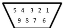
RS-232 Pinout
In order to communicate properly over RS-232, both the BGA244 and the host computer must be set to the same configuration. The RS-232 interface supports baud rates from 2400 to 115.2 k baud. In general, the highest baud rates will operate successfully for shorter cable lengths. At lower baud rates, cable lengths over 100m (300 ft) should be possible. Communication errors can be caused by excessive cable length, overly high baud rates or electrical noise. If errors occur, operating at a lower baud rate will usually help.
RS-422
The RS-422 connector (C4) can only be used if an external +24 VDC power supply is connected to the BGA244. Connections to the RS-422 interface are made using terminal block C4 located on the front of the BGA244.
The RS-422 interface is implemented as a 4 wire, point-to-point, non-multidrop connection. It supports a single transmitter and single receiver pair. Connections are made using a 5 pin terminal strip. Tx and Rx connections between the BGA244 and host should be made as follows. Note that the transmit pins on the BGA244 connect to the receive pins on the host and the receive pins of the BGA244 connect to the transmit pins of the host.
| BGA244 pin number | BGA244 Connection | Host Connection |
| C4-5 | +TxD | +RxD |
| C4-4 | -TxD | -RxD |
| C4-3 | +RxD | +TxD |
| C4-2 | -RxD | -TxD |
| C4-1 | GND | GND |
RS-422 Pinout

FIGURE 4: RS-422 SIGNAL PATH
Use twisted pair cabling with an impedance of 100Ω , especially for longer cable runs and higher data rates. Shielded Cat5 or Cat6 cable is a good choice. A 100Ω terminating resistor (R) can be added to each receive end for long cable runs or high data rates to improve signal quality. The resistor should be rated for at least 1/4 watts. The resistor can be connected along with the RxD lines at the BGA244 terminal strip.
In order to communicate properly over RS-422, both the BGA244 and the host computer must be set to the same configuration. The RS-422 interface supports baud rates from 2400 to 115.2 k baud. RS-422 can operate at cable lengths over 1000 m (3250 ft). In general, the highest baud rates will operate successfully for shorter cable lengths. Communication errors can be caused by excessive cable length, missing terminators, overly high baud rates or electrical noise. If errors occur, adding a terminator and/or operating at a lower baud rate will usually help.
Analog I/O Connections
The BGA244 has three analog outputs and two analog inputs. These features can only be used if an external +24 VDC power supply is connected to the BGA244. The analog I/O signals are located on C6 and C7. There are a number of different parameters that can be set for the analog inputs and outputs.
| Pin | Signal |
| C7-1 | Analog In 1 + |
| C7-2 | Analog In 1 - |
| C7-3 | Analog In 2 + |
| C7-4 | Analog In 2 - |
| C7-5 | Analog Out 1 + |
| C7-6 | Analog Out 1 – |
| C7-7 | Analog Out 2 + |
| C7-8 | Analog Out 2 – |
| C6-3 | Measure Out + |
| C6-2 | Measure Out - |
Analog I/O pinout
Analog Output
There are three separate Analog Outputs: Measure Out, Output 1 and Output 2. These can be independently set as voltage or current outputs. Measure Out is always linked to the Instrument Mode measured value. Outputs 1 and 2 can be linked to one of several different measured parameters or set explicitly by the user. The output full scale ranges can be scaled to match external devices. See Analog I/O (page 80) for information on configuring the outputs.
Voltage Outputs
The voltage outputs are unipolar and are ground referenced at the BGA244. The minus (−) outputs are connected to the BGA244s chassis ground. Avoid connecting the minus outputs to ground at the destination to avoid ground loops.
The voltage outputs have a maximum drive current of 20 mA and can drive capacitive loads of up to 1 µ F without oscillation. The output voltage may be reduced by resistive losses for long cable lengths and high currents. Make sure that the wire size, length and load current do not create excessive errors.

FIGURE 5: VOLTAGE OUTPUT
Current Outputs
The current outputs are unipolar and return to the BGA244s ground. The minus (−) outputs are connected to the BGA244s chassis ground. Avoid connecting the minus outputs to ground at the destination to avoid ground loops.
The current outputs have a compliance voltage of 16.5 V and can drive inductive loads up to 50 mH without oscillation. The maximum load resistance, including cable resistance, is 825 Ω. Cable resistance can be large depending on the length and wire size. Make sure that the cable resistance plus the load resistor is less than 825 Ω.

FIGURE 6: CURRENT OUTPUT
Analog Input
There are two separate Analog Inputs: Input 1 and Input 2. These can be independently set to measure voltage or current inputs. An internal loop power voltage source can be enabled for current input. Inputs 1 and 2 can be read on the front panel or over the computer interfaces. They can also be linked to a pressure transducer to monitor gas pressure. See Analog I/O (page 80) for details on configuring the inputs. See Pressure Transducers (page 31) for details on connecting pressure transducers to the analog inputs.
Voltage Input
The voltage input measures the differential voltage between the plus (+) and minus (-) lines. The input voltage range of either of the inputs is -0.1 to +20 V relative to ground. The differential voltage range from (+) to (-) is -2 to +10.2 V. This allows measurement of signals that are biased above ground.

FIGURE 7: VOLTAGE INPUT
Current Input
The current input measures the absolute value of the current from the plus (+) input to the minus (-) input. The signal can be either polarity, with a maximum of 24 mA. The voltage range at each input must be between -0.5 and +20 V; the burden voltage is 5.5 V for 20 mA. The wide voltage range and low burden voltage allows for multiple sense resistors or an external power supply in series with the current loop.

FIGURE 8: CURRENT INPUT
Current with Loop Power Voltage Source
Current Input with Loop Power is a special configuration of the current input mode that allow both signal and power to be transmitted over a pair of wires.
The Loop Power voltage source is ground referenced at the BGA244 and requires that the measured current returns to the minus (−) input. Devices that ground either current loop lead or require a floating loop power supply must use an external supply.
Hint: In general, devices using this feature should float with respect to the BGA244's ground. This feature may not operate properly if either current loop lead is connected to ground.
The maximum current amplitude is 24 mA. The Loop Power supply can be set between 6 and 19 V with a maximum output current of 50 mA.
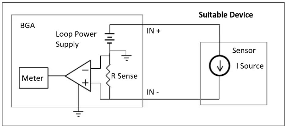
FIGURE 9: CURRENT INPUT W/ LOOP POWER (SUITABLE DEVICE)
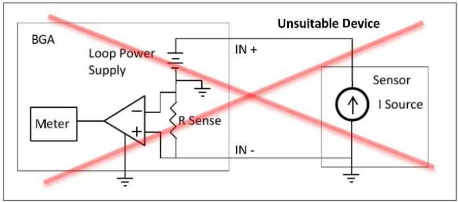
FIGURE 10: CURRENT INPUT W/ LOOP POWER (UNSUITABLE DEVICE)
Event Relays
There are two separate SPDT relays that are linked to the BGA244's Event 1 and Event 2 conditions. Events can be configured to switch for things like exceeded limits, loss of the measurement signal and system faults. They can also be directly set and cleared on the front panel or over the computer interfaces. See Events (page 55) for detail on configuring and controlling the Event Relays.
| Pin | Signal |
| C8-1 | Relay 1 Normally Open |
| C8-2 | Relay 1 Common |
| C8-3 | Relay 1 Normally Closed |
| C8-4 | Relay 2 Normally Open |
| C8-5 | Relay 2 Common |
| C8-6 | Relay 2 Normally Closed |
Event Relay pinout
These relays will operate only if an external +24 VDC power supply is connected to the BGA244. The relays are floating with respect to each other and chassis ground. Each relay consists of a common, a normally open and a normally closed connection. Normally open and normally closed refer to the relay in the de-energized state.
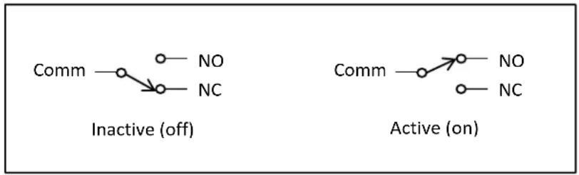
FIGURE 11: EVENT RELAY CONTACTS
The Event relay contacts are rated for the following conditions.
| Max Switching Power | 30 W, 62.5 VA |
| Max Switching Voltage | 60 VDC , 42.4 VPK , 30 VAC |
| Maximum Switching Current | 1 A |
| Maximum Carrying Current | 2 A |
| Lifetime (42 VDC , 0.1 A resistive load) | 106 operations |
Switching high power loads can dramatically reduce the relays lifetime. If driving an inductive load, make sure to use catch diode to minimize inductive fly-back.
Common uses of the relays include:
■ Turning on an alarm when a limit is exceeded
■ Opening a valve to control a process
■ Computer control of devices
Pressure Transducers
In many cases real time monitoring of the gas pressure can improve measurement accuracy. The simplest way to do this is by connecting a pressure transducer to one of the BGA244's analog inputs. This requires that the BGA244 is powered over 24 VDC to operate the analog inputs. Using the voltage or current analog inputs, the BGA244 can interface with a variety of different transducers. Scale factors for minimum and maximum pressures can be set, in either absolute or gauge pressure.
There is a wide variety of pressure transducers that can interface with the BGA244. Differences among them include gas fittings, pressure ranges and electrical connections. When selecting a pressure transducer, select one that matches the system operating pressure. Transducers typically have the best linearity and accuracy when not operated at their extreme limits.
Refer to Analog Inputs (page 80) for details on configuring the Analog Inputs.
Mounting Location
Locate the pressure transducer on the BGA244 side of any restriction to minimize offsets in the measured pressure. Make sure to account for any drop in pressure between the measured or regulated pressure and the BGA244 for large flow rates. Install the pressure transducers following their manufacturer's instructions.
Types of Pressure Transducers
The choice of which pressure transducer to use largely depends on the application it will be used in. Transducers come in many different ranges, fittings and accuracies. Choose a transducer with good sensitivity and accuracy and that matches the operating pressure of your system. If possible, use a transducer that reads in absolute pressure to eliminate ambient pressure variation.
The BGA244 can interface to most pressure transducers that output a voltage or current within the nominal analog input range. The BGA244 includes a selectable loop power voltage source that can be used to power many current output transducers. Transducers of this type are the simplest to integrate with the BGA244.
| Input | Minimum | Maximum |
| Voltage | 0 V | 10 V |
| Current | 4 mA | 20 mA |
Voltage Output Transducers
Voltage output pressure transducers have separate signal and power connections. In addition, they often have a drain wire that connects to the cable shield. They require an external power supply.
The BGA244 supports transducers with a full scale output range that lies between 0 and 10 V. Voltages must always be ≥ 0 V (no bipolar outputs). The output can be scaled to either absolute pressure or gauge pressure.
Connect an appropriate power supply per the manufacturer's instructions. If needed the Drain wire can be connected to ground at the BGA244 ground lug (C1). Connect the Signal and Signal Return (or +/- Signal) to +/- In 1 or In 2 on the BGA244. Refer to Analog Input (page 27) for details on connecting the transducer to the BGA244. Configure the BGA244 as described below.
■ Set the analog input to: Enabled, Voltage.
- Select Absolute or Gauge units, depending on the transducers specifications. If Gauge units are selected, make sure to enter the ambient pressure.
- Set the Min and Max to the transducers minimum and maximum pressure values.
- Check "Use as Pressure Gauge".
■ Set the Analysis Pressure to the appropriate input (Analog Input 1 or 2).
Current Output Transducers
Current output pressure transducers come in several different configurations. They can have separate power and signal lines or the power can be provided in series with the signal lines (loop power). In addition, they may have a drain wire that connects to the cable shield.
The BGA244 supports current output transducers with a full scale range of 4 – 20 mA. Currents can be either positive or negative. The output can be scaled for absolute pressure or gauge pressure.
The BGA244 can provide a loop power voltage source (6 – 19 V) if the transducer can accept a ground referenced voltage. See the pressure transducers manufacturers' information for specific details. Refer to Analog Input (page 27) for details on devices that are loop power compatible with the BGA244.
Hint: If either the + or - signal lines are connected to the pressure transducers body or drain wire, it probably won't work with the BGA244 loop power voltage source.
Transducers with External Power Supplies
Connect the appropriate power supply as described by the pressure transducer manufacturer. If needed, the Drain wire can be connected to ground at the BGA244 ground lug (C1). Connect the Signal and Signal Return (or +/- Signal) to +/- In 1 or In 2 on C7 on the BGA244. Refer to Analog Input (page 27) for details on connecting the transducer to the BGA244. Configure the BGA244 as follows.
■ Set the analog input to: Enabled, Current
- Select Absolute or Gauge units, depending on the transducers specifications. If Gauge units are selected, make sure to enter the ambient pressure.
- Set the Min and Max to the transducers minimum and maximum values.
■ Check: Use as Pressure Gauge.
■ Set the Analysis Pressure to the appropriate input (Analog Input 1 or 2).
Transducers with Loop Power
Connect the transducer Signal (or +) wire to +In 1 or 2 on the BGA244. Connect the Return (or -) wire to -In 1 or 2 on the BGA244. If needed, the Drain wire can be connected to ground at the BGA244 ground lug (C1). Refer to Analog Input (page 27) for details on connecting the transducer to the BGA244. Configure the BGA244 as follows.
■ Set the analog input to: Enabled, Current w/ Loop Power
- Set the Loop Power Voltage to the voltage specified by the pressure transducer manufacturer, typically 12-15 V.
- Select Absolute or Gauge units, depending on the transducers specifications. If Gauge units are selected, make sure to enter the ambient pressure.
■ Set the Min and Max to the transducers minimum and maximum values.
■ Check: Use as Pressure Gauge.
■ Set the Analysis Pressure to the appropriate input (Analog Input 1 or 2).
Chapter 3: Operation Guide
BGA244 User Interface
The BGA244 features a touch screen display that allows the user to set and display all settings and measurements. Units can also be fully configured and monitored over one of the three computer interfaces.
The description of the BGA244 features in this chapter is directed toward operating the unit from the display. Chapter 5: BGAMon contains information on operating the BGA244 using the BGAMon software. Chapter 6: Remote Programming contains information on the remote commands that can also be used to configure the BGA244.
Navigation
There are several navigation keys that are present on many of the pages to make it easier to navigate the different instrument functions of the BGA244. See Manual Conventions (page xviii) at the beginning of this manual for a list of conventions used to describe the different functions of the interface. The following rules will help you navigate the menus.
■ [HOME] returns you to the Home Page.
- [SETUP] take you to the configuration pages that aren't displayed on the Home page.
- [←] or back key returns up one level from the display you are currently on.
- [PAGE ↑] and [PAGE ↓] are used to scroll through a page that can't all be displayed on the screen at the same time.
- Different pages are referenced by their location in the interface hierarchy. (Home/Setup/Control Panel/Units) would be reached from the Home page by pressing [Setup] [Control Panel] [Units].
Help Screens
Most screens have a Help page associated with them accessed by a Help key. This page will have information about the settings and displayed parameters on the screen. The [Page ↑] and [Page ↓] are active if the Help screen is more than one page long.
Map of Interface Functions
![graph TD A["Home"] --> B["Limits"] A --> C["Scale"] A --> D["Events"] A --> E["Setup"] A --> F["Help"] F --> G["Start/Stop"] G --> H["Instrument Mode"] G --> I["Gases"] G --> J["Rel"] G --> K["Control Panel"] G --> L["Store Recall"] G --> M["Temperature"] G --> N["Pressure"] F --> O["Display"] F -->…](/content/2026/06/1372977/images/88963ce5bd36985390555bbbed5b83fd80f5dfd6638980cedbca34f0de814298.jpg)
FIGURE 12: MAP OF USER INTERFACE FUNCTIONS
Power On
When power is first applied, a power-on splash screen will appear.
After a few seconds the "About" information page will be displayed. This shows the unit serial number, firmware version, hardware information and calibration date.
After about 15 seconds the currently selected Home page will appear.
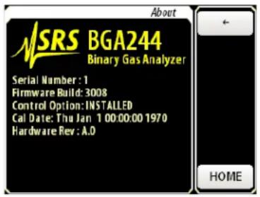
The three LEDs also indicate power on behavior. This is especially useful for units with the metal protective cover installed (Accessory BGA-M). When power is first applied, the Power LED will light for 1 second; followed by all 3 LEDs lighting for 5 seconds. At this time the Power LED should blinks once indicating the code is loading properly.
You can enter the screen calibration routine by pressing a finger to the screen when power is applied. Hold your finger down until the message “Release Screen to start Screen Calibration” appears, then follow the instructions to complete the routine. See Display later in this chapter for more information.
If the firmware detects a fatal error the unit will restart in the Factory Safe Mode. This will be indicated on the bottom of the About screen. Refer to Factory Safe Mode (page 203) for information.
Appearance
The BGA244 uses a touch screen display to configure measurements and display measurement results. The Home page displays the primary measurements and has controls to navigate the instrument functions and secondary measurements. You can always return to the Home page directly from any page by pressing [Home].
Each Instrument Mode has a unique Home page. Home pages consist of a Measurement Section that is specific to the Instrument Mode and a Control Section that is common to all Instrument Modes.
There are two possible appearances of the display depending on the orientation: vertical, with the control section below the measurement section and horizontal, with the control section to the right of the display section.
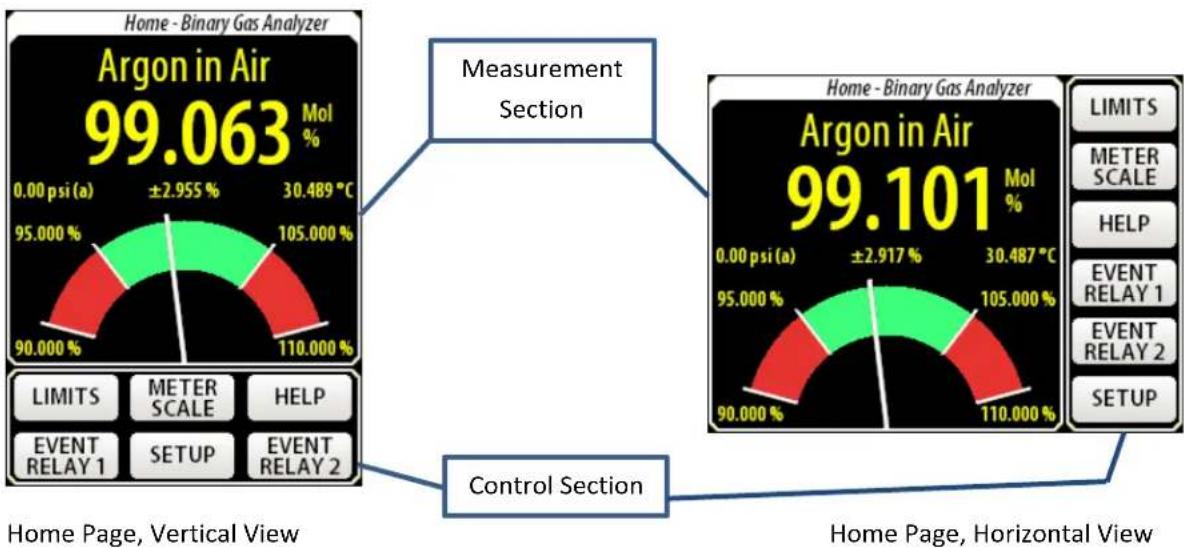
FIGURE 13: BGA244 HOME PAGE
Measurement Section
The Measurement Section displays the operating mode, measurements and status information. The meter scale, limits and other functions are set using keys in the Control section. See the sections on Binary Gas Analyzer (page 40), Gas Purity Analyzer (page 44) and Physical Measurements (page 47) later in this chapter for details on each Instrument Mode.
Screen messages can appear in the Measurement section. These indicate operating states, errors or problems with the measurements. See Screen Messages (page 50) for details on these functions.
Control Section
The Control Section is common to all Home pages. The Control buttons are used to set parameters and access menus within the user interface. Press the appropriate button to access that control. See Controls later in this chapter for details on setting each control.
Note: The touch screen on the BGA244 must be actually be pressed to activate functions. This is normally indicated by a key click or beep. Hovering over the button like you would on a cell phone or tablet won't activate the control.

Instrument Modes
The BGA244 can operate in one of three Instrument Modes: Binary Gas Analyzer Mode, Gas Purity Analyzer Mode and Physical Measurement Mode. The Instrument Mode determines the measurements made by the BGA244. Each Instrument Mode has a unique home page and measurement specific parameters (like gas selection, limits, and meter scale). See Instrument Mode (page 58) for more information.
Select Instrument Mode
Press [SETUP] to access the Setup page. This page has controls to configure the all of the instrument function besides those in the Control section.
Press [Instrument Mode ↓] to open the Instrument Mode list. Press the desired mode to select it. The currently selected mode is highlighted in yellow.
Binary Gas Analyzer
The Binary Gas Analyzer reports the fraction of one gas in a two gas mixture. Both gases must be known.
The Binary Gas Ratio is reported as the ratio of the primary gas in the mixture. Results are reported in percent (%), parts per million (ppm) or fraction (0 – 1.0). Go to (Setup/Control Panel/Units) to change the units. See the Units (page 73) for details on selecting units.
Principle of Operation
The speed of sound in an ideal gas can be approximated by:
W = √ γRT/M
Where W is the speed of sound, γ is the ratio of specific heat capacities ( γ = Cp/Cv ), M the molar mass, T the absolute temperature and R the ideal gas constant. For a gas mixture, γ and M are determined by the properties of each gas and their ratio within the mixture. By measuring the speed of sound and temperature of the gas mixture, and knowing the properties of each gas, the mole fraction of each gas can be precisely determined.
The speed of sound in real gases is somewhat more complicated. There are a number of gas specific effects that complicate the ideal case. These include thermo-viscous frequency shifts, temperature dependencies of heat capacity, dispersive effects and intermolecular (virial) effects that depend on both pressure and temperature. The BGA244 Factory Gas table contains data for these effects for nearly 500 different gases. See Appendix A: Gas Table for a detailed description of the properties used to characterize gases for the BGA244.
Binary Gas Analyzer Home Page

FIGURE 14: BINARY GAS ANALYZER HOME PAGE
■ Page Identification: Binary Gas Analyzer.
- Selected Gases: Primary Gas in Secondary Gas. Refer to Selecting Gases (page 58) for details.
■ Measured Value: Concentration of Primary Gas in the mixture.
- Units: %, ppm or fraction, and Mole/Mass fraction. See (Setup/Control Panel/Units) for units and (Setup/Control Panel/Measurement) for Mole/Mass fraction.
■ REL: Visible when the REL function is active.
■ Pressure: Measured or entered pressure used for analysis. See the Pressure (page 63) for more information.
■ Temperature: Measured gas temperature.
■ Accuracy: Estimated accuracy.
■ Upper & Lower Limits: Set by [LIMIT] in the Control section. See Limits (page 54) for more information.
■ Upper and Lower Scale: Set by [METER SCALE] in the Control section. See Scale (page 55) for more information.
■ Meter: Graphical display of the Measured Value on a graph scaled by the upper and lower scale values. The red areas are set by the upper and lower limit values.
Details
This is a description of some of the items specific to the Binary Gas Analyzer Instrument Mode.
Range
The maximum range for the Binary Gas Analyzer is -2% to +102% or its equivalent in fraction or ppm. The 2% over range is to allow for measurement inaccuracies. Outside of this range the display will limit at > (max) or < (min) to indicate out of range.
Selecting gases
Both the primary and secondary gases must be selected before measurements can be made. There are nearly 500 different gases contained in the BGA244 Factory Gas Table. Go to (Setup/Select Gas) to view the Gas Selection page. Here you can select the Primary and Secondary Gases by name, chemical formula or CAS#. See Selecting Gases (page 58) for more information.
Note that the BGA244 reports the ratio of Primary to the total mixture of the Primary and Secondary Gases. To report the concentration of the Secondary Gas, press [SWAP GASES] on the Gas Selection page.
Molar Fraction vs Mass Fraction
The BGA244 can report the gas ratio in either mole or mass fraction. These differ by the molar masses of the gases. Certain applications commonly use one or the other.
Go to (Setup/Control Panel/Measurement) to change between mole and mass fractions. See Binary Gas Concentration (page 74) for more details.
Accuracy Estimator
The BGA244 calculates a real time accuracy estimation of the gas ratio measurement. The accuracy estimation is based on temperature uncertainty of 0.1 °C and a pressure uncertainty of 1 psi.
REL
The REL (relative) function can be used to zero the ratio measurement to a reference gas. This can be either a pure gas, or a gas blend with a known ratio. See the REL (page 61) for more information. The REL indicator only appears when the REL function is active.
Dual Concentrations
There are a few gas combinations where there are two valid molar ratios for a given speed of sound. The ratio of these gases can be accurately determined for certain concentrations, but there can be two ratio values for a portion of the range. Both ratios are equally valid as far as the BGA244 can determine.
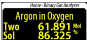
If a dual concentration is detected, the BGA244 reports both ratios. Concentration 1 is the smaller value and is displayed on top. Concentration 2 is the larger value and is displayed on the bottom.
Gas Purity Analyzer
This analyzer reports the purity of a gas as measured by the ratio of its measured speed of sound to its ideal speed of sound. The gas species must be known. This instrument mode is useful when measuring relatively pure gases. Results are reported in percent (%), parts per million (ppm) or fraction 0 - ±1.0 . Go to (Setup/Control Panel/Units) to change the units. Refer to Units (page 73) for details on selecting units.
Principle of Operation
The speed of sound of a pure gas at a known temperature and pressure is well known. Impurities will change this speed as a function of their mole fraction, molar mass and γ per the equation described in the Binary Gas Analyzer mode.
W = √ γRT/M
The definition of the Gas Purity in the BGA244 is:
ΔW/W = measured speed of sound - expected speed of sound/expected speed of sound
Both the expected speed of sound and the measured speed of sound are normalized to NTP (20°C, 1 atm) before calculating the ratio to eliminate temperature and pressure dependencies. Since temperature and pressure affect each gas differently, it's important to specify the gas being measured for best accuracy. See Appendix A: Gas Table for a detailed description of the properties used to characterize gases for the BGA244.
The gas purity is most sensitive when contaminants significantly heavier or lighter than the selected gas. If the purity measurement ( ΔW/W ) is positive, the contaminating gas is ordinarily lighter than the selected gas. Similarly if ΔW/W is negative, the contaminating gas is ordinarily heavier than the selected gas.
Gas Purity Analyzer Home Page

FIGURE 15: GAS PURITY ANALYZER HOME PAGE
■ Page Identification: Gas Purity Analyzer.
- Selected Gas: Gas name or reference speed of sound. See the Selecting Gases (page 58) for details.
■ Measured Value: ΔW/W
Units: %, ppm or fraction. See (Setup/Control Panel/Units) for unit selection.
■ REL: Visible when the REL function is active. (not shown)
■ Pressure: Measured or entered pressure used for analysis. See the Pressure section later in this chapter for more information.
■ Temperature: Measured gas temperature.
■ Accuracy: Estimated accuracy
■ Upper & Lower Limits: Set by [LIMIT] in the Control section. See the Limits section later in this chapter for more information.
■ Upper and Lower Scale: Set by [METER SCALE] in the Control section. See the Scale section later in this chapter for more information.
■ Meter: Graphical display of the Measured Value on a graph scaled by the upper and lower scale values. The red areas are set by the upper and lower limit values.
Details
This is a description of some of the items specific to the Gas Purity Analyzer Instrument Mode.
Select gas
The Primary (or Reference) Gas must be selected before measurements can be made (the Secondary Gas is not used for Gas Purity Measurements). There are nearly 500 different gases contained in the BGA244 Factory Gas Table. Go to (Setup/Select Gas) to view the Gas Selection page. Here you can select the Primary and Secondary Gases by name, chemical formula or CAS#. See Selecting Gases (page 58) for more information.
If you are using a blended gas that is not in the Gas Table, select the dominant gas species as the Primary Gas. Then use the REL function to set the current speed of sound as the reference. If your mixture doesn't have a dominant gas species, select a Primary Gas with a similar speed of sound to the mixture and use the REL function.
Accuracy Estimator
The BGA244 calculates a real time accuracy estimation of the gas purity measurement. The accuracy estimation is based on temperature uncertainty of 0.1\ °C and a pressure uncertainty of 1 psi.
REL
The REL (relative) function can be used to zero the measurement to a pure reference gas. See the REL section later in this chapter for more information on using this feature. The REL indicator only appears when the REL function is active.
Physical Measurements
The Physical Measurements Analyzer reports the physical measurements of a gas made by the BGA244. These include the
■ Measured Speed of Sound
■ Speed of Sound normalized to NTP (20°C, 1 atm)
- Temperature
■ Pressure
The speeds of sound are reported in m/s, kph or mph. The temperature is reported in °C, °K or °F. The pressure is reported in psi, atm, bar, Pa, mmHg or torr. Go to (Setup/Control Panel/Units) to change units. See Units (page 73) for more details.
Principle of Operation
The measured speed of sound is based on the resonant frequency measured in the cell, properties of the selected gases, measured temperature, analysis pressure and some calibration factors. Since temperature and pressure affect each gas differently, it's important to correctly specify the gases being measured.
The normalized speed of sound is the measured speed of sound normalized to NTP (20°C, 1 atm). The normalized speed of sound is typically the most useful measurement, since it can be compared to data taken at other temperatures and pressures.
Note that both measured and NTP speeds of sound are reported at their measured frequency. This is distinct from the gases speed of sound in free space which may be slightly different. The BGA244 only uses the speeds of sound at the measured frequency.
The temperature is the measured gas temperature. The pressure is the analysis pressure.
Physical Measurements Analyzer Home Page

FIGURE 16: PHYSICAL MEASUREMENTS HOME PAGE
■ Page Identification: Physical Measurements Analyzer.
■ Speed of Sound Normalized to NTP (20°C, 1 atm).
■ Measured Speed of Sound.
■ Temperature: Measured gas temperature.
■ Pressure: Measured or entered pressure used for analysis. See the Pressure section later in this chapter for more information.
■ Units: See (Setup/Control Panel/Units).
The Upper and Lower Limits are not displayed in Measurement section since there is no graph, but they are active. See Limits (page 54) for more information.
Details
This is a description of some of the items specific to the Physical Measurements Instrument Mode.
Select gas
Both the Primary and Secondary gases must be selected before measurements can be made. There are nearly 500 different gases contained in the BGA244 Factory Gas Table. Go to (Setup/Select Gas) to view the Gas Selection page. Here you can select the Primary and Secondary Gases by name, chemical formula or CAS#. See Selecting Gases (page 58) for more information.
The Primary and Secondary gas species have a small effect on the speed of sound measurements due to gas specific interactions with the BGA244. The Primary Gas should always be set to the dominant gas species. For pure gases, the Secondary Gas should be set to either a much lighter or much heavier gas (Hydrogen or SF6 are good candidates). For mixed gases, the Secondary Gas should be set to the gas with the second highest concentration.
Screen Messages
There are a variety of operating conditions that can be reported by the BGA244 (display versions only). There are several groups of messages including Analysis, Entry, Fault and Alert messages.
There are two types of screen messages. Normal messages appear as yellow or red text on the screen overwriting part of the Home page. These are notifications only and are referred to as “Messages”. Other messages are dual purpose, being both a notification as well as a navigation button. Pressing them will take you to the relevant page where more details are available. These are referred to as “Message Buttons”.
Analysis Messages
Messages appear in the measurement section to indicate something is affecting analysis within the BGA244. These items include user settings that may halt analysis, loss of signal and other analysis errors. All of these messages appear as text in the numeric display portion of the display.
Note that these messages may briefly appear at power on. This does not indicate any problems with the unit or measurement.
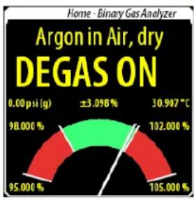
Degas On
This indicated that the Degas heaters are on and measurements can't be made. To return to the normal operating state, turn off the Degas heaters. See Heater (page 77) for more details.
102%, lt; - 2%
102% or <-2% (or their equivalent in ppm or fraction) indicate that the binary gas measurement is out of range for the selected gas combination. This can be caused by measurement inaccuracies in gases with similar speeds of sound, additional contaminating gas(es) in the cell or if the wrong gas(es) have been selected.
No Signal
This indicates that the BGA244 cannot recover the acoustic signal or identify a valid speed of sound for the gas. This most often occurs if the gas pressure in the cell is too low. See Troubleshooting (page 197) if this message is displayed with adequate gas pressure.
Invalid
This indicates that the BGA244 cannot report a valid result based on the measured speed of sound. Usually this only appears for a brief instant after a major disruption of the signal occurs. See Troubleshooting (page 197) if this message remains on for more than a few seconds.
Bad Pressure
This indicates that the measured pressure is invalid. It's usually caused by a problem with a pressure transducer or wiring connected to an Analog Input. See Pressure (page 64) for more information.
Condensation
This indicates that one or both of the gases is nearing its condensation point. When condensation occurs the BGA244 cannot correctly calculate the gas concentration, gas purity or normalized speed of sound. Refer to Condensation (page 95) for information on dealing with this problem.
Invalid Gas Message
This indicates that a recalled setting or configuration is referencing a nonexistent User gas. See Gas Selection (page 138) in Chapter 5 for more details.
Other Messages
Two Sol
Two Sol (Two Solutions) indicates there are two valid molar ratios for a given speed of sound. This can only occur for binary gas measurements. Concentration 1 is the smaller value and is displayed on top.
Concentration 2 is the larger value and is displayed on the bottom. This only occurs for a few gas pairs with
similar masses, but different γ 's. Refer to Gases (page 93) for more information.
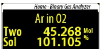
System Fault
This Message Button indicated that a serious problem has occurred with the BGA244. Pressing [SYSTEM FAULT] takes you to the Fault page. See Faults (page 84) for more details.

Alert
This Message Button indicates that non-critical problem has occurred. Pressing [ALERT] takes you to the Alert page. See Alerts (page 86) for more details.
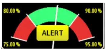
Stopped
This indicated that the BGA244 has been placed in the STOP mode and no measurements are being made.
Pressing the [STOP] key will take you to the Setup page
where the Run mode can be selected. Refer to RUN | STOP (page 58) for more details.

Invalid Entry
This message appears if an entered number is outside the allowable range. The minimum or maximum value for that entry is displayed.

LED Blink Codes
The Power and Error status LEDs are used to indicate the operating state of the BGA244. They can indicate power faults, system faults, analysis errors and communication errors using blink codes. These features are active on all units and are especially useful for units with the metal protective cover installed (Accessory BGA-M).. See Figure 1 (page 6) for the LED locations.
Normal Behavior
When power is first applied, the Power LED will light for 1 second; followed by all 3 LEDs lighting for 5 seconds. At this time the Power LED should blinks once indicating the code is loading properly then operational.
After this the Power LED remains on. The Comm (Communications) LED will flash during communication over any of the computer interfaces. The Error LED will remain off unless an error occurs.
ERROR LED Codes
These codes use the red ERROR LED to indicate various errors.
■ System Fault: The ERROR LED is continuously on as long as the condition persists.
- Stopped, Degas, Invalid, Bad Pressure, Condensation or No Signal: The ERROR LED flashes at about 4 Hz as long as the condition persists.
■ Communication Error: ERROR LED flashes once for each error.
POWER LED Codes
The BGA244 can indicate if the USB or +24 V power supplies are out of range using blink codes on the Power LED. Refer to External Power Supply Faults (page 84) for details. Note that the BGA244 must have a minimum power supply voltage to generate the blink codes.
■ Active Power Supply Fault: The POWER LED will flash at about 4 Hz.
Minimum Operational Voltage: USB ≥ 3.5V, +24 ≥ 18 V
USB Fault: Voltage < 4.5V or > 5.3V
+24 V Fault: Voltage < 20V or > 26V
Controls
Each Home page has the same Control section. Control buttons are used to access menus within the user interface. Several functions can be directly accessed from the Home page while others are accessed through the Setup Menu.
Note that the Physical Measurements Home page omits the Meter Scale control button since there is no meter. It replaces it with a Pressure Meter button.

Limits
Process limits are used to indicate that the measurement is above or below a set value. Limits serve two purposes in the BGA244. They are displayed on the meter to provide visual feedback (Binary Gas and Purity Analyzers) and are used in Events to control external devices.
The [LIMITS] button on the Home page is a dual purpose control. At any time, pressing [LIMITS] takes you to the Process Limits Page where the limit values can be entered. Additionally, the [LIMIT] button will turn red if either the Upper or Lower Limit is exceeded.
Process Limits Page
The upper and lower limits are set in units of the measured value. Each limit can be separately enabled. The Hysteresis value provides a guard band around the limit thresholds to avoid oscillating between the limit & non-limit states. This is particularly helpful when using the Event Relays to stop relay chatter.

The Upper Limit must be greater than the Lower Limit and within the operating range of the measured parameter. If not, an "Invalid Entry" message will appear with guidelines for a legal value.
If the Upper Limit has been exceeded, the measurement must drop below {Upper Limit – Hysteresis} to deactivate the Upper Limit. Similarly if the Lower Limit has been exceeded, it must rise above {Lower Limit + Hysteresis} to deactivate the Lower Limit.
Choose a hysteresis value that is reasonable for your limits. A hysteresis value of 1% may never reset if the limits are set to 0.01%.
Example:
For an upper limit set at 90% and the hysteresis set at 5%. If the measurement increased above 90%, the Upper Limit would be active. When deceasing, the Upper Limit wouldn't deactivate until the measurement dropped below 85%.
Scale (Binary & Gas Purity)
The [SCALE] button on the Home page opens the Meter Scale page. The Upper and Lower scale values are set in units of the measured value for the Binary Gas Analysis and Gas Purity modes. This control doesn't appear for the Physical Measurements mode. The Upper Scale value must be greater than the Lower Scale value and within the operating range of the measured parameter. If not, an Invalid Entry message will appear with guidelines for a legal value.
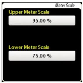
Pressure (Physical Measurements)
The [PRESSURE METER] button on the Home page opens the Analysis Pressure Meter page. See Pressure later in this chapter for more details.
Help
[HELP] takes you to a Help screen for the particular page you are on. Each Help page describes the parameters and settings for that page. There may also be suggestions to resolve problems or errors found on that page.
Event Relay 1 & 2
The Event Relays can be used to control external devices that depend on different conditions in the BGA244. These conditions can be individually enabled and include things like exceeded limits, loss of the measurement signal and system faults. There are two independent events relays: Event Relay 1 and Event Relay 2. If any enabled conditions are true, the Event Relay becomes active. If +24 V DC is not present, the Event Relays are not active.
The [EVENT RELAY] buttons are dual purpose controls. Pressing them takes you to the Event 1 or Event 2 configuration page where the event conditions are set. If an event is currently active, that event button will turn red as an indicator. If the Event Relay is in a Force On or Force Off state, that button will turn yellow to indicate that condition.
Event Relay Configuration Pages
Event 1 and Event 2 are set independently and have separate configuration pages. Any of the enabled conditions can activate an event. The following conditions can be selected. Use the [Page ↑] and [Page ↓] keys to navigate the Event list.
Any active condition in the Event list is displayed in red, whether it is enabled or not.
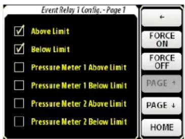
- Above Limit: Activates if the measured value is above the process upper limit. Setting the upper limit is described in Limits (page 54).
Below Limit: Activates if the measured value is below the process lower limit. Setting the lower limit is described in Limits (page 54).
- Pressure Meter 1 Above Limit: Activates if Pressure Gauge 1 is above the upper pressure limit. This selection is only available if Pressure Gauge 1 has been configured. Configuring the pressure gauge and limits is described in Pressure (page 63).
- Pressure Meter 1 Below Limit: Activates if Pressure Gauge 1 is below the lower pressure limit. This selection is only available if Pressure Gauge 1 has been configured. Configuring the pressure gauge and limits is described in Pressure (page 63).
- Pressure Meter 2 Above Limit: Activates if Pressure Gauge 2 is above the upper pressure limit. This selection is only available if Pressure Gauge 2 has been configured. Configuring the pressure gauge and limits is described in Pressure (page 63).
- Pressure Meter 2 Below Limit: Activates if Pressure Gauge 2 is below the lower pressure limit. This selection is only available if Pressure Gauge 1 has been configured. Configuring the pressure gauge and limits is described in Pressure (page 63).
- Temperature Above Limit: Activates if the Temperature Gauge is above the upper temperature limit. Configuring the Temperature gauge and limits is described in Temperature (page 66).
- Temperature Below Limit: Activates if the Temperature Gauge is below the lower temperature limit. Configuring the Temperature gauge and limits is described in Temperature (page 66).
- No Measurement: Activates if the BGA244 cannot report a valid measurement. Most of the causes of this are indicated as an Analysis Screen Message (page). See Troubleshooting (page 197) for possible causes.
■ System Fault: Activates if there is a serious fault with the BGA244. See Faults (page 84) for a list of possible System Faults.
Force On, Force Off Buttons
There are two additional buttons that manually control the Event Relays regardless of any event conditions. [FORCE ON] sets the relay to the ON state. [FORCE OFF] sets the relay to the OFF state. The selected Force button will turn yellow, as will the Event button on the Home page to indicate the force condition. Press the button a second time to release the force condition.
Event Relay Connections
Each Event Relay has three pins: normally open (NO), normally closed (NC) and common (COM). In the OFF state, NC is connected to COM and NO is open. In the ON state, NO is connected to COM and NC is open. The relays are in the OFF state when the BGA244 is powered off.
See Event Relays (Page 30) for details on wiring the relays to outside circuits. See the Specifications section for details on relay ratings and life time.
Using Event Relays
Event Relays are normally used to signal an out of range or error condition. They could be connected to a bell or horn to notify an operator of an out of range condition, or connected to a valve to increase the flow of a gas.
A common set up for Event 1 and Event 2 would be as follows.
■ Event 1: Above Upper Limit, Below Lower Limit
■ Event 2: System Fault, No Signal
The Event 1 Relay indicates if the measured value was above or below the set limits and Event Relay 2 would indicate that there was a problem with the measurement.
Setup
[SETUP] takes you to the Instrument Setup page which is described in the following section. From here you can access the remaining controls and settings of the BGA244.
Setup
The Setup menu accesses all the BGA244 controls that aren't directly available on the Home page. Press [SETUP] on the Home page to reach the Instrument Setup page.
The most important functions in the BGA244 can be directly accessed from the Setup page. Less commonly used functions are reached via the Control Panel. See the Map of Interface Functions (page 36) for the locations of different function controls.

Run|Stop
It's occasionally necessary to stop analysis and output updates. For example, you may not want alarm relays to activate or analog outputs to pin while changing gas cylinders or performing other system maintenance. Press [RUN] or [STOP] to switch between the run and stop states. When the BGA244 is stopped, a [STOPPED] message button will appear on the Home Page. Pressing this button takes you to the Setup Page where the [RUN|STOP] control is located.
When the BGA244 is stopped the following functions do not update:
Gas Ratio, Gas Purity, Speeds of Sound
■ Event Relays
■ Analog Outputs
■ Temperature Readings
Instrument Mode
The BGA244 can operate in one of three Instrument Modes: Binary Gas Analyzer, Gas Purity Analyzer and Physical Measurement. Each Instrument Mode has a unique Home page and measurement specific parameters (gas selection, limits, and meter scale).
Select Instrument Mode
Press [INSTRUMENT MODE ↓] to open the Instrument Mode list. Press the desired mode to select it. The currently selected mode is highlighted in yellow.

Selecting Gases
Measurements made with the BGA244 require selecting the gases to be measured. Two gases must always be entered: however the Gas Purity Analyzer only uses a single gas for its measurements.
The BGA244 Factory Gas Table contains nearly 500 different gases. Each entry includes the formula, common name, CAS # and up to two alternate names. All of these are scanned when selecting a gas. Besides naming information, an array of physical properties is stored with each gas for calculating gas ratios and speeds of sound. Appendix A contains a list of Factory Gas Table gases and a description of all of the gas properties.
Additional gases can be added into the User Gas Table. These can include mixtures or blended gases, made up of 2 or more single species gases. See User Gases (page 116) for more information.
To view the currently selected gases or to change gases go to (Setup/Select Gases). This page displays the information about the currently selected gases and has controls to change the gases.
The following information is displayed for each gas in the Factory Gas Table:
Gas ID (Primary/Secondary/Reference)
■ Chemical formula: The simple (non-structural) formula of the gas
■ Common Name of the gas
- CAS # The CAS Number is a unique identifier for every chemical substance described in open scientific literature.
■ MW (Molar Weight) of the gas molecule in AMUs (Binary Gas Analyzer and Physical Measurements)
- γ (gamma): The ratio of specific heat capacities (Binary Gas Analyzer and Physical Measurements)
■ Speed of Sound at NTP (Gas Purity Analyzer only)
How to select gases
Gases are selected at (Setup/Select Gases). Press [SELECT PRIMARY] or [SELECT SECONDARY] to open the alpha-numeric keypad.

Begin typing the name, formula or CAS # of the desired gas. As you enter characters, the BGA scans the entire gas Table for matches to the entered text and displays that number in the "Matches" field. If no gases match the entered text it displays "Matches: 0". If you press an incorrect key, press [←] to erase the last character or [CLR] to erase all characters.
When the number of matches is down to a manageable number (< 20 or so), press [ENT] or [ENTER]. This will open up a list of all of the matches from the gas table. Note that matches can occur at any position in the gas name, formula or CAS #. If there are more than 7 matches, use [Page ↑] and [Page ↓] to view the entire list. If you don't see the expected gas, press [←] to return to the alphanumeric entry window.

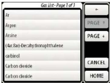
Select the desired gas by pressing its entry. This will enter the selected gas and return to the Select Gases page. If you wish to change the gas, press the desired gas selection key and re-enter the gas.
When selecting gases, User Gas Table gases will appear as "User/gas_name" to differentiate from a gas in the Factory Gas Table.
Swap Gases
For the Binary Gas Analyzer Mode, results are displayed for the concentration of the Primary Gas relative to the total mixture. If you want to view the concentration of Secondary Gas, press [SWAP GASES] which will exchange the two entries. This key will also swap the Reference Gas for the Secondary Gas in the Gas Purity Analyzer. It will also swap gases for the Physical Measurements mode, but this ordinarily has no effect on measurements.
Reference Gas (Gas Purity Analyzer)
For the Gas Purity Analyzer, the Primary Gas is referred to as the Reference Gas and the Secondary Gas is grayed out to indicate that only the Reference Gas is being used for this measurement.

REL
The BGA244 provides excellent accuracy using its internal calibration and its stored thermodynamic data. But there are circumstances where displaying deviations from an entered value may be useful. This can be used to track deviations from a reference gas or improve the measurement accuracy at a particular operating point. Typical uses for the REL function include:
- Setting a carrier gas to 0 or 100% when working with small concentrations of a dopant gas.
- Zeroing readings to a “reference mixture” and measuring the deviation from that value.
■ Using a REL value to compensate for an unknown pressure. - Using REL to measure deviations from a “reference point” when complete thermodynamic data isn’t available for a User gas.
The REL function is available for the Binary Gas Analyzer and the Gas Purity Analyzer Instrument Modes. When active, the "REL" indicator is displayed below the measurement units as shown on the Home pages.
The REL function performs the following operation:
displayedvalue = measuredvalue - RelValue
A REL is typically performed using a reference gas, either a pure gas or a well known mixture. In general, REL works best when operating near the conditions that the REL was performed at. Large deviations in temperature, pressure or concentration may make the technique less effective. Situations and techniques where the REL function can improve measurement accuracy are described in the Chapter 4: Application Guide.
Binary Gas Analyzer
Press ○Use REL or ○No REL to select or deselect the REL function.
Press [REL TO 100%] to set the measured value to 100% (or 1000000 ppm or 1.0 fraction). The value required to force the displayed value to 100% is displayed in the [Rel Value] button in global ratio units.
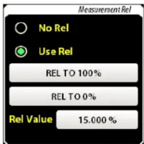
Press [REL TO 0%] to set the measured value to 0% (or 0 ppm or 0.0 fraction). The value required to force the displayed value to 0% is displayed in the [Rel Value] button in global ratio units.
You can also directly enter the Rel Value between -110% and +210% (or the equivalent in ppm or fraction). This value will be subtracted from the measured value to produce the displayed value.
Gas Purity
Press ○Use REL or ○No REL to select or deselect the REL function.
Press [REL TO 0%] to set the measured value to 0%. (or 0 ppm or 0.0 fraction). The value required to force the displayed value to 0% is displayed in the [Rel Value] button in global ratio units.

You can also directly enter the Rel Value between -110% and +210% (or the equivalent in ppm or fraction). This value will be subtracted from the measured value to produce the displayed value.
Pressure
The speed of sound in an ideal gas is independent of pressure. But the speed of sound in real gases does depend on pressure. For many gas(es) satisfactory measurements can be made without knowing the exact pressure. However to meet its specified accuracy for all gases, the BGA244 must know the gas pressure to within ± 1 psi (6.9 kPa). See the Applications Guide for information on the effects of pressure on measurement accuracy.
Pressure is the only external parameter that needs to be input to the BGA244 besides the gas species. It can be directly entered using the keypad or computer interface. Or a pressure transducer can be integrated with the BGA244 using one of the analog inputs.
Direct entry of the pressure is well suited for processes that operate at a fairly constant, known pressure. Typically the pressure is known by the system design or by monitoring an external gauge. This is the only method available if the unit is powered over USB.
Other processes may experience pressure variations over time or operating conditions. These applications will benefit from integrating a pressure transducer using one of the BGA244's analog inputs. This provides a simple, integrated solution to provide the best accuracy across a range of operating conditions. Using an external pressure transducer requires +24 VDC . Refer to Pressure Transducers (page 31) for information on connecting a pressure transducer to the BGA244.
Gauge Pressure vs Absolute Pressure
The BGA244 uses the absolute pressure of the gas as part of its calculations. However pressure can be input in either absolute pressure units or in gauge pressure units combined with the ambient pressure. This is true for both direct entry of User pressure or when integrating a pressure transducer.
Absolute pressure is relative to vacuum while gauge pressure is relative to the ambient pressure outside the gauge. The correct pressure units (gauge or absolute) must be selected in the BGA244 to avoid errors. If gauge pressure units are selected, the ambient pressure must also be entered. Refer to Pressure (page 98) for details.
Hint: If a pressure gauge or transducer can report negative pressures, it is reporting the gauge pressure. If it reports only positive pressures it can be either absolute or gauge. This should be listed on the pressure gauge specifications.
Press [PRESSURE] to access the pressure gauge setup menu. Here you can view the current pressure or select the pressure entry method for analysis and configure the external pressure gauge if needed. Pressure units are set on the Units page (Setup/Control Panel/Units section). Allowable units include psi, atm, bar, Pa, mmHg and torr.

Selecting Analysis Pressure
Press
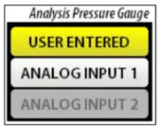
User Pressure
Press [ENTER USER PRESSURE] to manually enter the Pressure. Pressure can be entered in absolute pressure units (relative to vacuum) or in gauge pressure units (relative to ambient pressure). If you select gauge pressure units you must enter the ambient pressure.
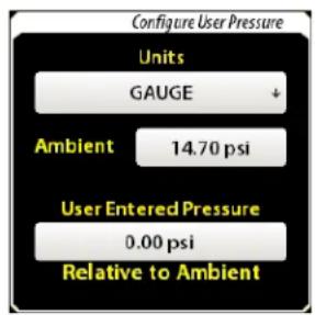
Example: The display to the right shows a gauge pressure of 0 psi, with an ambient pressure of 14.7 psi.
Configure Pressure Gauge
Press [CONFIGURE INPUT 1|2] to open one of the Configure Pressure Gauge pages. Typically only one of the two inputs is configured as a pressure gauge, but both selected can be if desired. Check the "Use as Pressure Gauge" box and select absolute or gauge pressure units. Be sure to enter the ambient pressure if using Gauge Pressure. Verify that the analog input is enabled and check that the Min and Max input format matches your transducer (V vs mA). If not, configure the input as described below.

Assuming the formats match, enter the pressure values for the minimum and maximum analog input values. If the analog output of your pressure gauge doesn't match the span of the analog input, calculate what the pressure would be at those points.
Example:
Your pressure transducer outputs 0 - 5 V DC for 0 - 50 psi
Set the following
Min (0V) amp; = 0. 0 0 psi amp; Max (10V) = 100.00 psi
Configure Input
Enable the Analog Input. Press [CONFIG INPUT] to open the Configure Analog Input page. Press
Certain pressure transducers can operate using loop power provided by the BGA244. This is the simplest type of transducer to integrate since it only requires 2 wires. See Analog Inputs (page 80) for details on different input types. If Current with Loop Power is selected, enter the appropriate loop power supply voltage.

![graph TD A["Input Type"] --> B["Voltage"] A --> C["Current"] A --> D["Current w/Lp Pwr"]](/content/2026/06/1372977/images/6ae41043204f49e98ccd090968b691a26bccb67b4c471f8fd18e98ef751d79f0.jpg)
An improperly configured analog input, broken pressure transducer or wiring can lead to out of range pressure readings. If this occurs, a “BAD PRESSURE” screen message will appear in place of the measurement and no results will be reported. There are also several alerts that can occur for the analog inputs. These normally indicate a problem with the device connected to the Analog Input or wiring, rather than the input itself. See Analog Inputs (page 80) for details.
Pressure Meter
There are pressure meter pages associated with each analog input when it's configured as a pressure gauge. Press [METER] on either the Pressure Gauge Setup or Configure Pressure Meter pages to view the pressure meter associated with that input. If an analog input is not configured as a pressure gauge that selection will be grayed out.

The Pressure Gauges each have a meter scale and limits similar to the Home page displays. Press [METER SCALE] to set the graph scale and [LIMITS] to set the Pressure Limit values. These are the over and under pressure limit values used on the Event Relay page.
Temperature
The cell temperature can also be displayed on a meter with limits and a scale. Press [TEMP] from the Setup page to view the temperature meter.
The Temperature Gauge has a meter scale and limits similar to the Home page displays. Press [METER SCALE] to set the gauge scale and [LIMITS] to set the Temperature Limit values. These are the over and under values limit used on the Event Relay page.
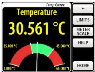
Store|Recall
The BGA244 can save and recall up to 20 different setups. Each setup contains all parameters that can be set on the BGA244; including the instrument mode, gas selection, display setup and I/O parameters. Stored setups can be given an alpha numeric name, making it easy to identify details about each setup. Press [STORE-RECALL] to access the Store Recall menu.
![graph TD A["STORE"] --> B["RECALL"] B --> C["ERASE"] C --> D["FACTORY"]](/content/2026/06/1372977/images/d580d4f9fd0b41a8c0593aff4fa669b0149b634f9f28c21bc26499d9b40267a7.jpg)

If a stored setup is over written or erased, it cannot be retrieved.
There are two setups that cannot be changed or deleted. The Default Setup configures the BGA244 as described in the Default Setup Table (page 68). The Factory Setup places the BGA244 into the same configuration as when it left the factory. See Factory Setup (page 71) for details.
Note: Setups are stored into Flash memory with a life time of about 100,000 erase cycles. Don't continuously store settings especially over the computer interfaces to avoid wearing out the memory.
If storing, recalling or erasing a setup fails once, try a second time. If it fails repeatedly, try a different location. This failure indicates a problem with the storage memory. See Troubleshooting (page 197) for more information.
Setup List
Pressing [STORE], [RECALL] or [ERASE] will open the Stored Setup list. This list contains the Default Setup and 20 available setup locations and their names. Use [Page ↑] and [Page ↓] to navigate the entire list. Filled setup locations are named; if no alpha numeric name was entered, the name "Setup x" is used ("x" is the setup location). Empty setups are denoted by "*Empty*".

Store
Press [STORE] to open the Setup list.
Press the desired setup. If the selected location is currently filled, a prompt will appear asking if you want to continue. You cannot store a setup to Location 0 (Default Setup)
Enter the setup name using the alpha-numeric keypad. If you selected a currently filled location a prompt will appear asking if you want to change the setup name.
A confirmation prompt will appear containing the setup name and if the setup was stored successfully.
When entering a name for a setup, try to be descriptive. For example, “ARGON IN OXYGEN, 1%” could indicate Primary Gas = Argon, Secondary Gas = Oxygen, full scale output = 1%. This makes it easier to identify each setup.
Recall
Press [RECALL] to open the Setup list. Note that Setup 0 is the Default setup.
Press the desired setup.
A confirmation prompt will appear containing the setup name and if the setup was recalled successfully.

Erase
Press [ERASE] to open the Setup list.
Press the desired setup. A prompt will appear asking if you want to erase the selected setup.
A confirmation prompt will appear if the setup was successfully erased.

Default Setup
TABLE 9: ACTIVE PARAMETERS
| Parameter | Value |
| Instrument Mode | Gas Purity Analyzer |
| Run Mode | Run |
| Gas Settings | |
| Primary/Reference Gas | Argon |
| Secondary Gas | Hydrogen |
| Pressure Settings | |
| Analysis Pressure | User |
| User Pressure | 0 psig |
| User Pressure Units | Gauge |
| Ambient Pressure | 14.7 psi |
| Meter Settings | |
| Purity Upper Scale | 5% |
| Purity Lower Scale | -5% |
| Purity Upper Limit | 2% |
| Purity Lower Limit | -2% |
| Purity Upper Limit Active | Active |
| Purity Lower Limit Active | Active |
| Purity Hysteresis | 0.1 % |
| Purity REL Mode | No REL |
| Purity REL Value | 0 % |
| Event Settings * | |
| Event 1 Configuration | Nothing Selected |
| Event 2 Configuration | Nothing Selected |
| Event 1 Force | No Force |
| Event 2 Force | No Force |
| Temperature Meter Settings | |
| Temperature Upper Scale | 50 °C |
| Temperature Lower Scale | 10 °C |
| Temperature Upper Limit | 40 °C |
| Temperature Lower Limit | 20 °C |
| Temperature Upper Limit Active | Active |
| Temperature Lower Limit Active | Active |
| Temperature Hysteresis | 1 °C |
| Display Settings | |
| Display Orientation | 0 degrees |
| Display Backlight | 10 |
| Display Key Click | On |
| Units Settings | |
| Ratio Units | % |
| Speed Units | m/s |
| Temperature Units | °C |
| Pressure Units | psi |
| Measurement Settings | |
| Average Mode | On |
| # Averages | 10 |
| Amplitude | Auto |
| BGA Concentration | Mole Fraction |
| Relaxation Correction | On |
| Heater Settings * | |
| Block Heater Mode | Off |
| Heater Temperature | 40 °C |
| Max Current | 2.0 A |
| Degas Heater | Off |
| Computer I/O Settings | |
| RS-232 | Enabled |
| Baud Rate | 9600 |
| RS-422 * | Enabled |
| Baud Rate * | 9600 |
| Analog Inputs Settings * | |
| Analog Input 1 | Enabled |
| Analog Input 1 Type | Voltage |
| Analog Input 1 Loop Power Voltage | 12 V |
| Analog Input 2 | Enabled |
| Analog Input 2 Type | Voltage |
| Analog Input 2 Loop Power Voltage | 12 V |
| Analog Output 1 Settings * | |
| Analog Output 1 | Enabled |
| Analog Output 1 Type | 0 – 10 V |
| Analog Input 1 Linked to | USER |
| Analog Output 1 User Value | 0 V |
| Analog Output 2 Settings * | |
| Analog Output 2 | Enabled |
| Analog Output 2 Type | 0 – 10 V |
| Analog Output 2 Linked to | USER |
| Analog Output 2 User Value | 0 V |
| Measure Output Settings * | |
| Measure Output | Enabled |
| Measure Output Type | 0 – 10 V |
| Measure Output Linked to | Purity Deviation |
| Measure Out Purity Scale Min | -10 % |
| Measure Out Purity Scale Max | +10 % |
| Misc. Settings | |
| Alerts | All Enabled |
| Use Password | Off |
| Password | 0000 |
* Settings marked with * are only operational when 24 V DC is connected to the unit. They can be configured even if 24 V DC is not present.
TABLE 10: INACTIVE PARAMETERS
| Parameter | Value |
| Binary Gas Analyzer Settings | |
| BGA Upper Scale | 105% |
| BGA Lower Scale | 95% |
| BGA Upper Limit | 102% |
| BGA Lower Limit | 98% |
| BGA Upper Limit Active | Active |
| BGA Lower Limit Active | Active |
| BGA Hysteresis | 1 % |
| BGA REL Mode | No REL |
| BGA REL Value | 0 % |
| Physical Measurement Settings | |
| Physical Upper Limit | 1000 m/s |
| Physical Lower Limit | 0 m/s |
| Purity Upper Limit Active | Inactive |
| Purity Lower Limit Active | Inactive |
| Purity Hysteresis | 1 m/s |
| Pressure Meter 1 Settings * | |
| Use Analog In 1 as Pressure Gauge 1 | Inactive |
| Gauge 1 Units | Gauge |
| Gauge 1 Min | 0 psi |
| Gauge 1 Max | 150 psi |
| Gauge 1 Upper Scale | 150 psi |
| Gauge 1 Lower Scale | 0 psi |
| Gauge 1 Upper Limit | 100 psi |
| Gauge 1 Lower Limit | 10 psi |
| Gauge 1 Upper Limit Active | Inactive |
| Gauge 1 Lower Limit Active | Inactive |
| Gauge 1 Hysteresis | 1 psi |
| Pressure Meter 2 Settings * | |
| Use Analog In 2 as Pressure Gauge 2 | Inactive |
| Gauge 2 Units | Gauge |
| Gauge 2 Min | 0 psi |
| Gauge 2 Max | 150 psi |
| Gauge 2 Upper Scale | 150 psi |
| Gauge 2 Lower Scale | 0 psi |
| Gauge 2 Upper Limit | 100 psi |
| Gauge 2 Lower Limit | 10 psi |
| Gauge 2 Upper Limit Active | Inactive |
| Gauge 2 Lower Limit Active | Inactive |
| Gauge 2 Hysteresis | 1 psi |
| Analog Output 1 Settings * | |
| Analog Output 1 Speed Scale Min | 0 m/s |
| Analog Output 1 Speed Scale Max | 2000 m/s |
| Analog Output 1 Speed NTP Scale Min | 0 m/s |
| Analog Output 1 Speed NTP Scale Max | 2000 m/s |
| Analog Output 1 Temp Scale Min | 0 °C |
| Analog Output 1 Temp Scale Max | 50 °C |
| Analog Output 1 Press 1 Scale Min | 0 psi |
| Analog Output 1 Press 1 Scale Max | 150 psi |
| Analog Output 1 Press 2 Scale Min | 0 psi |
| Analog Output 1 Press 2 Scale Max | 150 psi |
| Analog Output 2 Settings * | |
| Analog Output 2 Speed Scale Min | 0 m/s |
| Analog Output 2 Speed Scale Max | 2000 m/s |
| Analog Output 2 Speed NTP Scale Min | 0 m/s |
| Analog Output 2 Speed NTP Scale Max | 2000 m/s |
| Analog Output 2 Temp Scale Min | 0 °C |
| Analog Output 2 Temp Scale Max | 50 °C |
| Analog Output 2 Press 1 Scale Min | 0 psi |
| Analog Output 2 Press 1 Scale Max | 150 psi |
| Analog Output 2 Press 2 Scale Min | 0 psi |
| Analog Output 2 Press 2 Scale Max | 150 psi |
| Measure Out Settings * | |
| Measure Output Linked to | Gas Concentration 1 |
| Measure Out BGA Scale Min | 0 % |
| Measure Out BGA Scale Max | +100 % |
| Measure Out Physical Scale Min | 200 m/s |
| Measure Out Physical Scale Max | 2000 m/s |
* Settings marked with * are only operational when 24 VDC is connected to the unit. They can be configured even if 24 VDC is not present.
Factory Setup
Caution: Loading the Factory Settings will erase all stored setups as well as the User Gas Table. This procedure cannot be "Un-done" so be certain that you want to do it before starting.
The Factory Setup is used to set the BGA244 to the condition it left the factory. This involves:
■ Erase Stored Settings 1-20
■ Delete the User Gas Table
■ Recall Setup 0 (Default Setup)
Press [FACTORY] to load the factory setup. A prompt will appear asking if you want to recall the Factory Setup. Press [YES] to continue or [CANCEL] if you don't want to recall the Factory Setup.
A second prompt will appear to confirm that you really want to restore the Factory Setup. Press [YES] to continue or [CANCEL] if you don't want to recall the Factory Setup.
A confirmation prompt will appear to confirm that the factory setup was recalled successfully. Press [OK] to continue.


Control Panel
The remainder of the controls and measurements in the BGA244 are accessed through the Control Panel. Press [CONTROL PANEL] to access this menu. Use [PAGE ↑] or [PAGE ↓] to navigate the different functions. Press the Function name to enter that page. The Control Panel menu includes:
| Display |
| Units |
| Measurement |
| Status |
| Heater |
| Computer I/O |
| Analog I/O |
| Faults |
| Alerts |
| Message Log |
| Self Test |
| Password |
| About |
Display
Since the BGA244 can be mounted in any orientation, the display needs to be rotated for proper viewing. The back light intensity and key clicks can be set. In addition, the screen coordinates can be calibrated. Press [DISPLAY] to access the Display controls.

Display Orientation
The display can be viewed from 4 different orientations, indicated by the four arrow buttons.
Press whichever arrow points up to rotate the display where that direction is up.
Backlight Intensity
The display backlight intensity can be varied from full on (10) to nearly off (1). In high brightness conditions the backlight should always be set to full intensity.
Reducing the backlight intensity minimize the power supply current. Setting it to the minimum reduces the current by nearly 100 mA. This is really only useful when operating the BGA244 off of poor quality USB power and isn't commonly done.
Press [] to increase the back light intensity. Press [] to decrease the back light intensity.
Key Click
The key click can be turned on and off. They should normally be left on to provide feedback that a key was pressed but can be turned off if necessary.
Press Key Click [ON] or [OFF] to turn the Key Click sound on and off. When turning the key click off you will hear the final click as the button is pressed. When turning it on there is a longer beep.
Screen Calibration
The resistive touch screen used in the BGA244 can drift over time. This can cause the active location of buttons and controls to not align correctly with the graphics. This drift is normally quite slow, but large temperature changes can accelerate it. If the key push location isn't aligned well with the screen graphics, use the following procedure to calibrate the screen.
■ Press [CAL SCREEN] to begin the screen calibration process.
■ Touch the center of each crosshair as prompted.
- When the calibration is complete the BGA244 will return to the Home page.
You can also enter the screen calibration routine by pressing a finger to the screen when power is applied. Be sure to continue holding your finger down until the message "Release Screen to start Screen Calibration" appears, then follow the instructions to complete the routine.
Units
The BGA244 displays several different types of measurements including ratios, speeds of sound, temperatures and pressures. Each measurement can have one of several different units.

Ratio
Ratio units are used in measurements that are ratios of one quantity to another. They are used for gas concentration (Binary Gas Analyzer) and ratio of speeds of sound (Gas Purity Analyzer).
Allowable units are: fraction (0 to ±1.0 ), % (percent) and ppm (part-per-million). Press

Speed
Speed units are used for speeds of sound measurements. They are primarily used on the Physical Measurements page.
Allowable units are: m/s, kph (kilometers/hour) and mph (miles/hour). Press

Temperature
Temperature units are used for gas temperature readings and heater settings.
Allowable units are: °C, °K and °F. Press

Pressure
Pressure units are used for gas pressure readings.
Allowable units are: psi, atm, bar, Pa, mm/Hg and torr. Press
Note that for pressure setting and entry the pressure units are defined as either absolute units (relative to vacuum) or gauge units (relative to atmospheric pressure). This selection is made on the Configure Pressure Gauge or Configure User Pressure pages. See the Pressure section earlier in the chapter for more information.
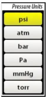
Measurement
The default configuration for the BGA244 is optimized for a wide range of gases, pressures, temperatures, flow rates and other environmental conditions. However there are circumstances when measurement and analysis can be tuned for better performance. Refer to Chapter 4: Application Guide for conditions when optimizing these parameters may be useful.
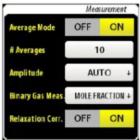
Averaging
Averaging successive measurements can improve accuracy and repeatability of the measurements by reducing interfering signals and noise. See Using Averaging (page 104) for more information. The BGA244 takes a measurement every 228 ms. This is quite a bit faster than most processes change, so a moderate number of averages doesn't create a noticeable delay.
The averaged output is continuously calculated, producing a new averaged measurement for every input measurement following the formula:
Average _ N = [1 / N * Measure _ N] + [(1 - 1 / N) * Average _ N - 1]
For signals without large transients, the averaged value settles to within 1% of its final value in about 5 * N measurements or N * 1.14 seconds. For the default value of 10 averages the averaged output settles in about 11.4 seconds.
Large transients may persist in averaged measurements for a long time. They may take several times as long to decay as the normal settling time. Similarly, any changes in a measurement will only be visible if they last for a sufficient number of samples.
Press [OFF] or [ON] to turn averaging on and off. Enter the number of averages between 2 and 100.
Amplitude
The amplitude of the speaker signal is optimized for the best signal to noise ratio of measurements within the acoustic cell. In rare cases this amplitude may cause the acoustic signal to over or under load the preamplifier. The BGA244 detects this and adjusts the amplitude accordingly. When this occurs there is a brief period when measurements are invalid until the acoustic signal settles to the new value, reported by an Invalid screen message.
Ordinarily the amplitude should be left in the default auto setting. If numerous Invalid screen messages due to amplitude changes appear, it may be helpful to set the amplitude to a lower fixed value. View the message log to see if an Invalid message is due to an amplitude change.
Press

Binary Gas Concentration
Binary gas measurements can be reported in one of two formats: mole fraction and mass fraction. See Converting Mole Fraction (page 108) for a detailed description of the relationship between them.

Press
The currently selected method will be highlighted in yellow. Press the desired value to select it.
Relaxation Correction
Gases take different amount of times to reach thermodynamic equilibrium between their translational, rotational and vibrational degrees of freedom. If that amount of time is comparable with an acoustic cycle of the resonant mode, a small correction factor is applied to the applied to the heat capacity used to compute the speed of
sound. Most gases don't exhibit this effect. For the few gases that do, the effect is small and corrected. However in some cases, carbon dioxide (CO2) can exhibit varying amounts of this effect depending on other gas species present.
Relaxation Correction should be left in the default setting (on) for nearly all cases. See Relaxation Effects (page 94) for details on when this should be turned off. Press [ON] or [OFF] to turn relaxation correction on and off.
Status
This page lists the present value of most of the parameters measured by the BGA244. If a parameter isn't currently configured in the BGA244 it will be dashed out (----). Use [PAGE ↑] and [PAGE ↓] to navigate the list of measured parameters.

List of Monitored Parameters
Speed of Sound (Measured)
Speed of Sound (NTP)
Gas Temperature
Analysis Pressure
Block Temperature
PCB Temperature
Heater Power
USB Voltage
External Voltage
Analog In 1 Value
Analog In 2 Value
Measure Out Value
Analog Out 1 Value
Analog Out 2 Value
Heater
The BGA244 heaters serve several purposes. They are used to stabilize the measured gas temperature, to prevent condensation and to help with high purity bake out. There are two separate heaters: the Block Heater and the Degas Heater. Information on settling time and specific uses of the heaters is available in the Chapter 4: Applications Guide.
Note: The Gas temperature will usually not match the block temperature due to heat flow in the gas and acoustic cell. In addition, the Block and Set temperatures may differ by a few degrees. This is normal for the BGA244.
The Heaters can only be used if an external +24 VDC power supply is connected to the BGA244. The maximum Block Heater current drawn from the external supply can be set between 50 mA and 2.2 A. The current draw of the Degas Heater is fixed at about 140 mA.
The Block Heater can be used during either analysis or bake out. The Degas Heater cannot be used during analysis. If the Degas Heater is active, a “DEGAS ON” message is displayed on the Home page. See Screen Messages (page 50) for more information.
Block Heater
The Block Heater can apply over 50W of power to heat the cell temperature to as high as 70 °C. The Block Heater is over-temperature and over-current protected.
The Block Heater uses a temperature servo to maintain the temperature of the cell to the set point. It will hold the temperature stable assuming the following conditions are true.

- The Block Heater temperature set point is at least 3 degrees above the highest ambient temperature.
- The Maximum Heater Current is large enough so the heater can raise the cell temperature up to the Block Heater set temperature for the lowest ambient temperature.
Press Heater [ON] or [OFF] to turn the Block Heater on and off. Enter the Heater Temperature between 0 and 70 °C. Enter the Maximum Current between 0.05 and 2.2A.
The endplate temperature and power being applied to the BGA244 is reported. The Regulating Indicator shows when the temperature servo is actively regulating the temperature. A Heater Regulation alert will appear if the heater is not regulating. See General Alerts (page 87) for details.
Note: It is normal for the [Heater Regulation] alert to appear when the block heater is first turned on or for large change in the ambient or set temperatures.
This can last for a considerable period of time, especially when the set temperature is reduced by more than a few degrees.
If the heater cannot regulate after several minutes, try the following:
- If the cell temperature is above the set temperature, increase the set temperature. If the maximum set temperature is exceeded (70 °C), it may be necessary to either allow the BGA244 to operate without temperature regulation or to reduce the temperature of the gas or the environment. Remember to not exceed the maximum operating temperature (70 °C).
- If the cell temperature goes below the set temperature, increase the maximum heater current. If the maximum allowable heater current cannot raise the temperature to the required temperature, the operating environment temperature needs to be increased. A simple way to do this is to add insulation around the BGA244.
Degas Heater
The Degas Heater can only be used during system bake out. It is normally used in conjunction with the Block Heater to bake out the BGA244 cell for use high purity systems. The Degas heaters operate by heating the speaker and microphone Kapton membranes directly. They each draw about 70 mA and provide about 0.25 W of heat. The BGA244 cannot make gas measurements while the Degas Heater is active. This is indicated on the Home Page by the “DEGAS ON” screen message.
Press Degas [ON] or [OFF] to turn the Degas Heater on and off.
Computer I/O
The BGA244 has three separate computer interfaces that can control and monitor all functions. Details on controlling the BGA244 over the computer interfaces are described in Chapter 6: Remote Programming.
The USB and RS-232 interfaces will operate for either USB or 24 VDC power. The RS422 requires that an external +24 VDC power supply is connected to operate.
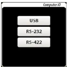
The RS-232 and RS-422 interfaces can be enabled and disabled and have settable baud rates from 2400 to 115.2k baud. The USB has no enable or configuration functions. Press [USB], [RS-232] or [RS-422] to access that interfaces page.
Receive and Transmit Buffers
Each interface has its own set of receive and transmit buffers that show the most recent commands and responses over that interface. They can be helpful when debugging communication problems. Press the [BUFFER] key on the interface page of interest to view.

USB
Nothing can be set for the USB interface. The only control on the USB page is the [BUFFER] key. Press it to view the transmit and receive buffers.
RS-232
Press [DISABLE|ENABLE] to enable or disable the RS-232 interface. Press [BUFFER] to view the transmit and receive buffers.
Press
Parity: None
# of Bits: 8
Stop Bits: 1
Flow Control: CTS/RTS
The following RS-232 communication problems are reported in the Message Log (page 88).
- Parity Error
■ Break
Frame Error
RS-422
The RS-422 Interface page is similar to the RS-232 page. [ENABLE | DISABLE],
Note that 24 VDC must be present for the RS-422 interface to be operational.
The following RS-422 communication problems are reported in the Message Log (page 88).
■ Parity Error
■ Break
Frame Error


Analog I/O
The BGA244 has two analog inputs and three analog outputs that can be used to interface to external devices, sensors or meters. Refer to Analog I/O (page 26) for details on connecting the analog inputs and outputs to external circuits. See the Specifications for details on the analog inputs and outputs performance. The Analog Inputs and Outputs will only operate if an external +24 V DC power supply is connected.

Analog Inputs
The two Analog Inputs (INPUT 1 and INPUT 2) can each be set to measure either voltage, current or current with a loop power voltage source. The measured voltage or current can be viewed on the BGA244 or read over one of the computer interfaces. Press [INPUT 1] or [INPUT 2] to go to their configuration page.

Analog inputs can be used as either general purpose
inputs, or together with a transducer as a pressure meter. If an analog input is configured as a pressure meter it may not be used for general purpose measurements. In either case the input must be configured properly for the desired measurement. The Input reading displayed on this page is in V or mA regardless if the analog input is used as a pressure meter.
[CONFIG PRESSURE] takes you to the Configure Pressure Gauge page as described in Pressure (page 63) earlier in this chapter. To set an input to general purpose, uncheck "Use as Pressure Gauge" on the Configure Pressure Gauge page.
Press [ENABLE|DISABLE] to enable or disable the analog input. Press
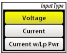
The Loop Power Voltage can be entered if Current w/Loop Power is selected. This can vary from 6 and 19 V. See Analog Input (page 27) for details on devices that can use loop power.
There are several alerts that can occur for the Analog Inputs. They appear as red text at the bottom of the Analog Input page as well as on the Alert page. These normally indicate a problem with the device connected to the Analog Input or wiring, rather than the input itself.
| Name | Valid for | Indicates |
| Undervoltage | Voltage | Input < -0.2 V |
| Overvoltage | Voltage | Input > 10.2 V |
| Undercurrent | Current | Input < 4 mA |
| Overcurrent1 | Current | Input > 20 mA |
| Loop Power2 | Current w/ Loop Power | Loop Power current is > 50 mA |
1 The Input 1/2 Overcurrent condition switches out the current sense resistor when the input current exceeds 26 mA. It will automatically switch the current sense resistor back in when the input voltage drops below 5.8 V. In some cases it may be necessary to manually reset an overcurrent fault due to the behavior of the external circuitry.
2 Loop Power 1/2 Alert switches out the Loop Power voltage source. It does not self clear and must be cleared manually.
Most of these Alerts except Loop Power self clear if the condition that caused them goes away. See the Message Log for a history of transient events. See Alert (page 86) for details on alert behavior.
Analog Outputs
There are three separate Analog Outputs that can be configured as 0 – 5 V, 0 – 10 V or 4 – 20 mA outputs. Measure Out is always linked to the measured value of the selected instrument mode. Outputs 1 and 2 can be linked to one of several different measured quantities or set explicitly by the user. Outputs linked to a measured quantity can be scaled to match a specific range using global units. For example, Measure Out can be scaled so a 0 to 1% gas concentration corresponds to a 0 to 10 V output to interface to an external device.
Use the Scale Min and Scale Max values to scale the analog output relative to the linked parameter. Scale Min is the value for the minimum analog output (0 V or 4 mA). Scale Max is the value for the maximum analog output (5 V, 10 V or 20 mA). Scale Min and Max are always set in the selected Global Unit for that parameter.
Example: In Binary Gas Analyzer mode, the Measurement Output is always linked to the Gas Concentration ratio (%, ppm or fraction). So Scale Min and Scale Max are entered as ratios.
Example: Analog Output 1 can be linked to the gas temperature (°C, °K or °F). In this case, Scale Min and Scale Max are entered as temperatures.
If the values of the linked parameters exceed the Scale Min or Scale Max values, the Analog Outputs will pin to their respective minimum or maximum values.
If the full scale ranges of the external device and the analog output don't match, you can still calculate what the measured output would be for the minimum and maximum analog output values.
Example: You need a 1 to 8 V output for a Gas Concentration of 10% to 20%.
Use the 0 – 10 V setting for the Measure Output.
7V corresponds to 10%, so 1V \~ 1.43%
Scale Min (0V) = 10% - 1.43% = 8.57%
Scale Max (10) = 20% + (2 * 1.43%) = 22.86%
There are two alerts that can occur for the Analog Outputs. They appear as red text at the bottom of each Analog Output page and on the Alert page. These normally indicate a problem with whatever is connected to the Analog Output rather than a problem with the output itself.
- IOut Alert indicates that the current output can't output the required current. This usually indicates a break in the 4-20 mA current loop or an overly large series resistor.
- Temperature Alert indicates the output driver has overheated and is in thermal limit. This usually indicates that the output is shorted.
These alerts self clear if the condition that caused them goes away. See the Message Log for a history of transient events. See Alerts (page 86) later in this chapter for details on alert behavior.
Measure Output
Measure Out is always linked to the measured parameter set by the Instrument Mode as follows. See the specific Instrument Modes for details on the measurements.
■ Binary Gas Analyzer: Gas Concentration Ratio
■ Gas Purity Analyzer: Speeds of Sound Ratio
■ Physical Measurements: Normalized speed of sound

The present Output Value (voltage or current) is displayed just below Scale Max.
Press [ENABLE|DISABLE] to enable or disable the output. Press

Select Gas Concentration 1 or 2 using

Enter Scale Min and Scale Max to scale the Measure Output relative to the value of the measured parameter. They are in ratio units for the Binary Gas and Gas Purity, or in speed units for Physical Measurements.
Output 1 and Output 2
Analog Output 1 and 2 can be linked to several different parameters or be explicitly set from the GUI or computer interface as a User value. Analog Output 1 and Output 2 scale in the same manner as the Measure Output if linked to a measured parameter. Possible linked parameters include:
■ Measured Speed of Sound
■ Normalized Speed of Sound (to NTP)
Gas Temperature
■ Pressure Meter 1 or 2 (if configured)
■ User: Set thru the GUI or over the computer interfaces.

See Physical Measurements (page 47) for information on the measured speed of sound, normalized speed of sound and the temperature. See Pressure (page 63) for details on pressure measurements.
Press [ENABLE| DISABLE] to enable or disable the output. Press
Press
![graph TD A["Output Selection"] --> B["SPEED OF SOUND"] B --> C["SPEED (NTP)"] C --> D["GAS TEMPERATURE"] D --> E["PRESSURE 1"] E --> F["PRESSURE 2"] F --> G["USER VALUE"]](/content/2026/06/1372977/images/81f9a869d67d793574db38b12cdde71380b028e168ac7e2647d48181a5032ea0.jpg)
If User Value is selected, a User Setting entry box will appear below "Linked to". Enter a value within the full scale range for that output type. Otherwise enter the Scale Min and Scale Max values for the linked parameter.
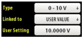
The present Output Value (voltage or current) is displayed just below Scale Max or User Setting.
Faults
The BGA244 monitors several critical parameters. An Instrument Fault is generated if any of these goes out of range. These faults indicate that something serious is wrong with either the BGA244 or the power supplies connected to it. These faults are listed on the Faults page and can be read over the computer interface (see Remote Programming, page 160). See Troubleshooting (page 197) for further details.
Faults will self-clear if the problem causing them goes away. To view transient events go to the Message Log. There are three main types of faults: External Power Supply Faults, General Faults and Self Test Faults.
If any fault occurs, the red [System Fault] button appears on the Home page and the [Home] button turns red on all pages. Pressing [System Fault] takes you to the Faults page.

If an External Power Supply occurs, the POWER LED will flash at \~4 Hz. If a General or Self Test Fault occurs, the ERROR LED will stay on continuously.
External Power Supply Faults
If the BGA244's power supply input voltages fall outside the specified range, an external power supply fault will be generated. The +5V USB power supply is monitored only when the unit is powered over USB (no +24 V DC ). Otherwise the External +24 V DC power supply is monitored. The following faults are displayed on the Faults page and are indicated by the Power LED blinking at about 4 Hz. See Power (page 22) for details on power supplies and cabling.
Note: There must be a minimum voltage ( 3.3 V for USB, 18 V for the External +24) for the BGA244 to control the display or lite any LEDs.
TABLE 11: EXTERNAL POWER SUPPLY FAULTS
| Fault Name | Meaning |
| USB Undervoltage | External USB Supply < 4.45V |
| USB Overvoltage | External USB Supply > 5.50V |
| 24V Overvoltage | External 24 Supply > 28V |
| USB Undervoltage Fault: | This is usually caused by a USB port that cannot provide sufficient current or a high resistance USB cable. |
| USB Overvoltage Fault: | This fault may be caused by a faulty USB supply or poor quality cable. |
| 24V Overvoltage Fault: | This fault indicates a faulty or improper power supply. Confirm that the 24 VDC Power Supply is appropriately rated. |
General System Faults
General System Faults are critical errors that occur while the BGA244 is operating. These faults indicate a problem with the internal circuitry or a serious temperature problem. The following faults are displayed on the Faults page and are indicated by the ERROR LED staying on continuously.
TABLE 12: SYSTEM FAULTS
| Fault Name | Meaning |
| Under Temperature | Cell Temperature reads < -20 °C |
| Over Temperature | Cell Temperature reads > 80 °C |
| Flash Fault | Fatal Error in Flash Memory |
| Firmware | Error in Firmware Update |
| Heater Fault | Block Temperature reads > 90 °C |
| 1.4V Under Voltage | Internal 1.4V Supply too low |
| 1.4V Over Voltage | Internal 1.4V Supply too high |
| 3.3V Under Voltage | Internal 3.3V Supply too low |
| 3.3V Over Voltage | Internal 3.3V Supply too high |
| 5V_I Under Voltage | Internal 5V Supply too low |
| 5V_I Over Voltage | Internal 5V Supply too high |
| Temperature Mismatch | >5°C Mismatch on Temperature Measurements |
Self Test Fault
The BGA244 runs a series of Self Tests at power on, or when requested from the Self Test page or the *TST command over the computer interfaces. A Self Test fault is generated if any of the Self Tests fail. See Self Test (page 88) for more details.
Faults Page
The Faults page provides a list of all currently active Faults. Use [PAGE ↑] and [PAGE ↓] to navigate the list of Faults. If the faulting condition goes away, the Fault will self-clear and be removed from the list. To view transient events go to the Message Log.

Alerts
Alerts are warnings of non-critical conditions. These may be problems with the BGA244 or with external devices or wiring.
If an alert occurs, the yellow [Alert] button appears on the Home page and the [Home] button turns yellow on all pages. Pressing [Alert] takes you to the Alerts page. Each Alert can be cleared or disabled using its Alert Action Window.

Most Alerts will self-clear if the problem causing them goes away. Transient events can be viewed on the Message Log. There are three main types of alerts: Analog I/O Alerts, Temperature Alerts and General Alerts.
Analog I/O Alerts
There are a number of alerts that can occur for the Analog Inputs and Outputs. These normally indicate a problem with whatever is connected to the Analog Input or Output and not a problem with the BGA244. All Alerts except the Input 1/2 Loop Overcurrent will self clear when the condition causing them is eliminated. See Analog I/O (page 80) for details on the specific alerts.
TABLE 13: ANALOG I/O ALERTS
| Alert Name | Meaning |
| Input 1 Undervoltage | Input 1 < -0.1 V (V In only) |
| Input 1 Overvoltage | Input 1 > 10.2 V (V In only) |
| Input 1 Undercurrent | Input 1 < 3.5 mA (I in only) |
| Input 1 Overcurrent | Input 1 > 26 mA (I in only) * |
| Input 2 Undervoltage | Input 2 < -0.1 V (V In only) |
| Input 2 Overvoltage | Input 2 > 10.2 V (V In only) |
| Input 2 Undercurrent | Input 2 < 3.5 mA (I in only) |
| Input 2 Overcurrent | Input 2 > 26 mA (I in only) * |
| Input 1 Loop Overcurrent | Input 1 Loop Power current is > 50 mA |
| Input 2 Loop Overcurrent | Input 2 Loop Power current is > 50 mA |
| Measure Output Current | Measure Out cannot output the required current |
| Measure Out Temp | Measure Out Over Temperature |
| Output 1 Current | Output 1 cannot output the required current |
| Output 1 Temp | Output 1 Over Temperature |
| Output 1 Current | Output 1 cannot output the required current |
| Output 1 Temp | Output 1 Over Temperature |
* In some cases it may be necessary to manually reset an overcurrent fault due to the behavior of the external circuitry. See Analog Inputs (page 80) for details
Temperature Alerts
There are several alerts that indicate that the cell temperature is out of range or there are discrepancies between the two temperature sensors.
TABLE 14: TEMPERATURE ALERTS
| Alert Name | Meaning |
| Under Temperature | Cell Temperature < 0 °C |
| Over Temperature | Cell Temperature > 70 °C |
| Temperature Mismatch | Mismatch between temperature sensors > 2 °C |
General Alerts
These Alerts are for conditions not included in other alert tables.
TABLE 15: GENERAL ALERTS
| Alert Name | Meaning |
| USB Undervoltage | External USB Supply < 4.6 V |
| USB Overvoltage | External USB Supply > 5.3 V |
| 24V Undervoltage | External 24 Supply < 22 V |
| 24V Overvoltage | External 24 Supply > 26 V |
| Heater Not Regulating | The Cell Heater is not regulating |
| Factory Safe Mode | A fatal error caused the unit to re-boot to Safe Mode. |
The Under and Over Voltage Alerts indicate that the power supply input voltages are marginal. The +5V USB power supply is monitored only when the unit is powered over USB (no +24 VDC ). Otherwise the External +24 VDC power supply is monitored. These alerts may indicate a problem with the power supply or cabling. See Power (page 22) for details on power supplies and cabling.
Heater Not Regulating indicates that the heater servo is set to its minimum or maximum values and is not correctly regulating the cell temperature. It is only active when the heaters are on. Note that this Alert normally appears when the heater is first turned on or if the ambient or set temperatures are changed. See Heater (page 77) for more details.
Factory Safe Mode indicates that the BGA244 software encountered a fatal error and restarted to the Factory Safe Mode. Refer to Factory Safe Mode, page 203 for details.
Alerts page
Each Alert appears as a separate multipurpose button on the Alerts page. Use [PAGE ↑] and [PAGE ↓] to navigate the list of Alerts.
Most Alerts self clear and vanish when the problem causing them goes away. Pressing a particular [ALERT] button will take you to its Alert Action Window that allows you to control the appearance and behavior of the alerts. Note that all alert actions are lost if the power is cycled.

Alert Actions
Press [CLEAR ALERT] to clear a currently active alert. This is only useful for alerts that are not self clearing. Other Alerts will immediately re-assert themselves after being cleared, since they are still active.

Press [DISABLE ONCE] to ignore a currently active alert. This will cause the alert to be ignored and clear the alert indicators
(assuming this is the only active alert). The Alert button will turn lite grey to indicate its "disabled once" state. If this alert is cleared and later re-asserted, it will revert to the normal "un-ignored" state, with the alert indicators active.
Press [DISABLE ALWAYS] to permanently ignore an active alert. This will cause the alert to be ignored and clear the alert indicators (assuming this is the only active alert). The Alert button will turn dark grey to indicate its “disabled always” state. If this alert is cleared and later re-asserted, it will remain inactive with the Alert added to the list in dark grey until power is cycled.
Press [ENABLE ALL ALERTS] to return all alerts to the active state. This will clear any "Disable Once" or "Disable Always" behavior. Note that power cycling the BGA244 will always enable all alerts.
Message Log
The Message Log is a list of the most recent events that occur in the BGA244. This includes stored and recalled settings, alerts, faults and other messages. The Message Log can be particularly useful in diagnosing transient events that may disappear before they can be properly diagnosed.

Self Test
The Self Test page provides access to the Self Test functions and their results.
Running Self Test
Running Self Test will stop all measurements and can temporarily modify inputs, outputs and relay settings for several seconds. Self Test is the same procedure that is run upon power on or by the computer interface *TST command.

To begin Self Test, press [START SELF TEST]. The tests and their results will be written to the screen. Upon completion, the BGA244 will display "SELF TEST PASS" or "SELF TEST FAIL". Use [PAGE↑] and [PAGE↓] to navigate the list of tests. If Self Test fails it will be listed on the Faults page.
In a properly operating unit Self Tests should pass every time. See Troubleshooting (page 197) for information about Self Test failures.
TABLE 16: SELF TESTS
| Test Name | Description |
| 3.3 V Supply | Internal 3.3 V Power Supply is within range |
| 1.4 V Supply | Internal 1.4 V Power Supply is within range |
| 4.5 V Supply | Internal 4.5 V Power Supply is within rangeNot performed on Rev C hardware |
| USB Supply | External USB Power Supply is within rangeNot performed if +24V is present |
| 24 V Supply | External 24 V Power Supply is within rangePerformed if +24V is present |
| 5 V Industrial Supply | Internal 5 V Power Supply is within rangePerformed if +24V is present |
| CODEC | CODEC is detected |
| ADC 1 | ADC 1 is detected |
| ADC 2 | ADC 1 is detected |
| USB | FTDI USB chip is detectedPerformed only if USB power or USB host is connectedIncludes part number & serial number |
| Thermistors | Thermistor 1 & 2 resistance is within range |
| Thermistors Single Ended | Low side of thermistor terminals is not shorted to the case |
| Membrane 1 | Membrane 1 resistance is within range |
| Membrane 2 | Membrane 2 resistance is within range |
| Magnet 1 | Magnet 1 field is within range |
| Magnet 2 | Magnet 2 field is within range |
| Analog Output | Output DACs are detectedPerformed if +24V is present |
| Analog Input | ADC is detectedPerformed if +24V is present |
Password
The BGA244 keypad can be locked out with a password enable to keep unauthorized personnel from changing settings on the BGA244. When locked out only the home page can be viewed.
If keypad is locked, a message appears at the top left of the screen. Any key press will open the numeric key pad to allow the user to enter the password. An "Invalid Password" prompt will appear if an incorrect password is entered. After the correct numeric password has been entered, all functions can be accessed. If locking is enabled, the keypad will be re-locked after 30 seconds of no keypad activity.

Press [ON] or [OFF] to turn locking on and off. A new password can be entered if locking is on. Enter a 4 digit numeric value to change the password.
If you forget the password, the unit can be reset using Hard Reset function described in the Hardware Reset section. This will disable password locking and reset the password to the default value of 0000.
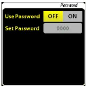
About the BGA244
The About the BGA244 page displays the following information. This is the same information that is displayed on the display during power on.
- Serial Number
- Firmware Version
■ Calibration Date
■ PCB Version
Cell Version
■ (if active) Factory Safe Mode

"Factory Safe Mode" will only be displayed if the BGA244 encountered a fatal software error that caused the unit to re-boot. Refer to Factory Safe Mode, page 203 for details.
Hardware Reset
The BGA244 has a hardware reset button that can be used if the BGA244 is frozen in an inoperable state. There are two different types of resets with slightly different behaviors.
Use an unbent paper clip or a small screw driver to press the reset button.
Normal Reset
Press the reset button once. Releasing the button forces a Normal Reset. This acts the same as power cycling the BGA244. This is ordinarily used if the BGA244 is in an unknown state and it is difficult to remove power to restart the unit.
Hard Reset
Press the reset button once. Release it, then immediately press and hold the button down for at least 10 seconds to execute a Hard Reset. This acts the same as power cycling the BGA244 and Recalling Setup 0 (Default Setup). This is ordinarily done if something has occurred to put the BGA244 in an inoperable state where loading the Default Setup is impossible, or to reset a forgotten password.
Note that this will replace the current settings of all parameters with the Default Settings. See Default Setup (page 68) for details.
Factory Safe Mode
If the firmware has detected a fatal error the unit will restart in the Factory Safe Mode. This will be indicated on the bottom of the About screen. Refer to Factory Safe Mode, page 203 for information.
User Gases
Gases can be added to the User Gas Table using the BGAMon software or over one of the computer interfaces. See User Gases (page 116) in Chapter 4 for details on this procedure.
Updating Firmware
The BGA244 Firmware can be updated by the user using the BGAMon software. See Updating Firmware (page 143) in Chapter 5 for details on this procedure.
Chapter 4: Application Guide
This section provides information on using the BGA244. It includes details on gases, pressure, operating conditions, measurements, high purity use and adding User gases.
Gases
The BGA244 determines the concentration and purity for a wide variety of gases. It does this by measuring the speed of sound and temperature and then determines the mixture ratio or gas purity using the physical properties of the gases.
The fastest speed of sound that can be measured is 1400m / s , the speed of sound for hydrogen (2 amu). The slowest is less than 130 m / s , the speed of sound for SF6 (146 amu). This range covers nearly all compounds that are gaseous within the operating temperature and pressure range of the BGA244.
Gas Requirements
Gases must be clean and dry. This means they cannot contain any solid or liquid particulates. Gases that contain solid particulates must be filtered before entering the BGA244. It may be necessary to operate the BGA244 at an elevated temperature to ensure there are no liquid particulates in the gas stream. Gases must not contain oils or waxes can coat the inside of the acoustic cell or Kapton acoustic transducers.
Gases must be non-condensing and contain no liquid particulates at the temperature and pressure the BGA244 is operating. If a gas is nearing its condensation point the BGA244 will indicate a condensation warning message. See Condensation (page 95) for more information.
Supported Gases
The BGA244 Factory Gas Table contains nearly 500 different gases. These include common industrial gases and a wide range of specialty gases. See Appendix A: Gas Table for a list of supported gases.
Gases not included in the Factory Gas Table can be added using the User Gas Table. This supports a simple model of a gas as compared to the Factory Gas Table. See User Gases (page 116) for more details.
Gases aren't constrained to single species. Gases mixtures or blended gases can also be used. Atmospheric air (N2, O2, Ar, CO2) is included in the Factory Gas Table. Other mixed gases can be added to the User Gas Table using the procedure described later in this chapter.
Gases that should be used with caution
Certain gases or mixtures can be problematic for the BGA244. Caution should be used with gases that react with the wetted materials. See Specifications for a complete list of wetted materials. Contact SRS if you have questions about compatibility of a particular gas or mixture with the BGA244.
Explosive or Flammable Mixtures
The BGA244 is not ATEX rated. Under normal operating conditions the BGA244 cannot ignite the gas being analyzed. However, if the instrument is used with flammable or explosive gas mixtures SRS recommends the use of flame arrestors on both gas ports.
The BGA244 gas cavity's proof pressure (2,500 psia) is sufficient to contain the denotation of an explosive gas mixture of up to 30 psia (207 kPa). The instrument would not operate after such an event.
Corrosive Mixtures
Some gases can react with certain of the wetted materials. Copper is used in two places in the BGA244: the OHFC end gasket and the acoustic membrane.
SRS recommends using the BGA244HP for corrosive mixtures as it replaces the standard OFHC copper gasket with a gold flashed version.
The instrument's acoustic transducer consists of an ENIG (Electroless nickel, covered by a thin gold layer) plated copper spiral on a 40µm thick Kapton polyimide film. It can be susceptible to:
■ Gases that react strongly with copper
■ Strong bases (NaOH, KOH) that may react with Kapton film
We recommend corrosion testing of this component on a case-by-case basis. Contact SRS for additional information.
Unusual Gas Properties
Certain gases or gas combinations may have properties that may affect the accuracy of their measurements.
Relaxation Effect
Relaxation (or dispersion) is a non-linear molecular effect that can be modeled as a frequency dependence of the heat capacity of the gas. Most gases fully equilibrate (or relax) in less than one cycle of their resonant mode within the acoustic cavity. Of the gases that don't, most take far longer than a single resonant cycle. A very few gases do neither. These gases exhibit a pressure dependent shift in the speed of sound. In most cases this shift is small, only a few 100 ppm. Depending on the gas species involved, a second gas may cause the mixture to equilibrate more rapidly.
Carbon dioxide (CO2) is unique in that it has a very large relaxation effect at the frequencies of its resonant modes for lower gas pressures. This distorts the acoustic signal, leading to larger errors or unrecoverable signals. To avoid this effect, the minimum recommended operating pressure for CO2 is around 12 psia (83 kPa), although the detection threshold is less than 8 psia (55 kPa).
Most gases added to CO2 will not affect its relaxation time, with the notable exception of water vapor. A mole fraction of 0.5% water vapor reduces the relaxation time of CO2 by about 15 times which dramatically reduces its effect. Hydrogen will also reduce the relaxation time, but only by about 1.5 times. Alcohols may also have an effect.
The BGA244 includes data to correct relaxation effects for its measurements. This correction should be left in the default setting (on) for almost all cases. See Relaxation Correction on page 75 for details.
Low pressure measurements of CO2 that contain water vapor may benefit from turning off relaxation correction. The water vapor can be either the second gas of a ratio measurement or a contaminant in the CO2 .
Reactive or Dimerizing gases
A reactive gas mixture can produce new gas species. A dimer is a molecule made up of two identical simpler molecules. The analysis techniques used in the BGA244 assumes that the molecules are non-reactive and non-dimerizing.
Condensation
The BGA244 cannot measure gases that are at or near their condensation point. There are two main reasons for this. Actual condensation will interfere with the acoustic cavity making it difficult or impossible to accurately determine the speed of sound. Plus the thermodynamic properties of a gas change radically as it transitions from its gaseous to liquid state. This change makes it impossible to calculate the gas composition and normalized speed of sound. In extreme cases, condensation can actually fill the cell with liquid.
Before actual condensation occurs, pre-condensation can interfere with measurements. During each cycle of the acoustic signal, the pressure within the acoustic chamber increases and decreases slightly. For a gas near condensation, this pressure increase can take the gas into the non-linear region causing large measurement inaccuracies.
Condensation is a function of a particular gas species, its current vapor pressure and temperature. The relative concentration of the gas in a mixture has no effect. Condensation will occur if the temperature is low enough that the vapor pressure of the gas exceeds its saturation value.
Ordinarily gases flowing through the BGA244 aren't near their condensation point. But there are several things that could cause them to condense.
- A reaction may occur at elevated temperatures relative to the BGA244. Condensation may occur when the gas passes into the cooler BGA244.
- The BGA244 can be used to monitor and control the output of a bubbler in a dilution flow. The temperature of the gas bath is adjusted to control the gas concentration. If the BGA244 is operated at a lower temperature than the bath, condensation can occur.
- The BGA244 may be operated at an ambient temperature that is below that of the gas, leading to condensation.
Condensation Warning
The BGA244 contains condensation data on the gases in the Factory Gas Table. By knowing the gas species, concentration, temperature and pressure the BGA244 can detect if the gas is near its condensation point and display a “Condensation Warning” screen message. The BGAMon software also provides information if the conditions and selected gas species are near condensation.
Note that the condensation warning depends on the BGA244 being filled with only to the two gases selected. It is possible for condensation to occur without warning if a non-selected gas gets into the chamber.
Avoiding Condensation
To avoid condensation, ensure that the saturation point (pressure at which condensation occurs) of the gas species exceeds the partial pressure of the gas within the BGA244. The following techniques can be used to eliminate condensation.
The Block Heaters can be used to raise the cell temperature. The temperature should be high enough so the saturation value of the gas exceeds the partial pressure of the gas. If this temperature is unknown, set the Block Heater to operate at least 3-5 °C above the highest expected gas manifold temperature up to the maximum of 70 °C. Make sure the power supply and Maximum Heater Current are large enough to raise the cell temperature to the set point (typically 0.5 to 2 amps). Refer to Heater (page 77) for information on setting the heater.
Water Vapor in Air
Atmospheric air usually contains some water vapor in addition to the usual nitrogen, oxygen, argon and carbon dioxide. This is referred to as humidity. It will affect measurements since water vapor is an additional gas species. Ordinarily mixtures containing water vapor as a third gas should be dried prior to measurement. However in some cases, drying can be avoided by using the REL function to compensate for the third gas.
For this technique to work the amount of water vapor in the “wet” air must be fixed. If it changes, a new REL must be performed. The amount of water vapor must also be low enough to avoid condensation. Note that the condensation point of water (or any liquid) is independent of any other gas species. But it does depend on both temperature and pressure. BGAMon can be used to see the saturation point (maximum amount of water vapor) for your operating temperature and pressure. It may be
necessary to operate at an elevated temperature if the water vapor is approaching condensation.
As with any REL, this technique works best near the conditions the REL was performed at. This means operating at a similar temperature, pressure and (most importantly) amount of water vapor in the wet air. Errors will increase the as the operating conditions move further away from the REL conditions. Refer to REL to a Reference Gas (page 105) for more details about this procedure.
Procedure
It is usually a good idea to know the approximate amount of water in the air before performing a REL. This serves two purposes. First it determines if the cell temperature should be increased using the heaters to avoid condensation. Second it provides a check to see if the amount of water vapor has changed since the unit was last REL'd.
Select dry air and water in the gas selection menu. Flow 100% wet air through the cell. If a condensation warning occurs, increase the cell temperature using the block heaters. Record the amount of water vapor in the wet air to compare with future measurements. A new REL should be performed whenever the amount of water vapor changes. It may be helpful to track the atmospheric temperature and relative humidity.
Next select dry air and the second gas to be measured in the gas selection menu. Be sure that wet air is still flowing through the cell. Go to the REL menu, select “Use REL” and press either [REL to 0%] or [REL to 100%], depending on your measurement. (Remember that the BGA244 graph reports the fraction of the primary gas in the mixture.) Return to the Home page. The reading should be very nearly the exact value selected on the REL page, either 0 or 100%.
Water Vapor in Other Gases
This technique is generally applicable to any gas that contains water vapor.
Pressure
Operating Pressure
The BGA244 can operate over a wide range of pressures, starting from a few psi (\~10 kPa) up to 150 psi (1000 kPa). Operating near atmospheric pressure, \~15 psi (\~100 kPa), provides good results if you have the flexibility to select the operating pressure.
Pressure Effects in Gases
Several thermodynamic properties of gases have pressure dependent terms that cause their behavior to diverge from the ideal gas law. These effects are significant for some gases. Sudden changes in pressure may also cause transients in the measured readings. See Transients (page 102) in this chapter for more details.
The largest departure from the ideal gas law is caused by intermolecular effects (effects between gas molecules). This causes a change in the speed of sound as a function of pressure. These are commonly modeled as virial coefficients. The graph below shows the shift in the speed of sound for pure SF6, a gas with a fairly large frequency shift vs pressure.
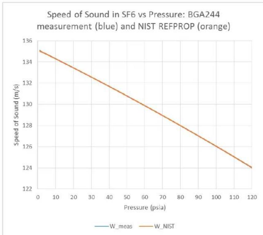
FIGURE 17: SPEED OF SOUND VS PRESSURE IN SF6
These frequency shifts directly affect the Gas Purity and Physical Measurements modes. Their effect on the binary gas ratio is more complicated, since this also depends on the relative molecular masses of the two gases.
Is Pressure Information Necessary?
There are cases where the BGA244 can make satisfactory measurements without precise pressure information.
■ Best accuracy is not required.
■ Using gases that have small variations due to pressure.
■ Using the REL function to improve accuracy at a fixed pressure.
Unless one or more of these is true, it's necessary to know the gas pressure. The BGAMon software can indicate measurement sensitivity to pressure variations.
To meet the specified accuracy for all gases, the pressure must be known to within ±1 psi (6.9 kPa). This information can be directly entered into the BGA244 or measured by a pressure transducer interfaced to one of the analog I/O ports as described in the Pressure Transducers (page 31).
Estimating pressure
Tip: If your system vents to the atmosphere, the operating pressure is probably around 1 atm (14.7 psia or 101 kPa).
Compensating using REL
The REL function can be used to compensate for a lack of pressure information in some cases. This technique works best when deviations from a reference gas or reference mixture are more important than the absolute accuracy. It is most accurate for small deviations from the reference point; larger deviations are less well compensated. This REL will only be valid for the gas or mixture it was performed on. A new REL should be performed whenever anything that can affect the gas pressure is changed. This may include different flow rates, new gas cylinders, regulators or MFC's.
Minimum Operating Pressures
The minimum operating pressure that the BGA244 can make accurate measurements depends on the mass of the gas mixture. Below this minimum the accuracy of the measurements may be degraded. Table 17 lists the recommended minimum operating pressures for pure gases. All values are listed in absolute pressure units (relative to vacuum). Use Averaging at low pressures to improve the detection limit and stability of measurements. The default value of 10 averages is a good place to start, but values of 20 or more may be necessary some cases.
At very low pressures the BGA244 cannot reliably recover the acoustic signal. A “No Signal” message will be displayed in place of the measurement if this occurs. (See Screen Messages, page 50 for details).
TABLE 17: RECOMMENDED MINIMUM OPERATING PRESSURES FOR PURE GASES
| Gas | Minimum Pressure |
| H2 | 10 psia (69 kPa) |
| He | 10 psia (69 kPa) |
| CH4 | 5 psia (34 kPa) |
| N2 | 3 psia (21 kPa) |
| Ar | 3 psia (21 kPa) |
| CO2 | 12 psia (83 kPa) |
| SF6 | 2 psia (14 kPa) |
Pure CO2 (carbon dioxide) has an unusually high minimum operating pressure due to relaxation effects. For best accuracy the operating pressure should be at least 12 psia (83 kPa). Refer to Relaxation Effects (page 94) for more details.
Since the average mass of the gas is what sets the minimum operating pressure, mixtures of He or H2 and any other gas will be able to be measured at lower pressures than pure Helium or Hydrogen.
Ambient Pressure Variation
Ambient pressure varies only slightly due to weather. The default ambient pressure is 14.7 psia (101 kPa) which corresponds to the average atmospheric pressure at sea level. A typical low ambient pressure at sea level is about 14.5 psia (100 kPa); a typical high pressure is about 14.9 psia (103 kPa).
Elevation has a much larger effect on ambient pressure. The typical atmospheric pressure in Denver, Colorado at 5280' (1610 m) is 12.2 psia (84 kPa). Setting the ambient pressure based on the elevation and ignoring any weather effects should only introduce a small error for devices using gauge pressure units. However for best accuracy the ambient pressure should be measured and updated whenever it changes by more than 0.5 psi (3.4 kPa).
Operating Conditions
Warm Up Time
The BGA244 can make measurements immediately after power-on. The accuracy may improve slightly after warmup due to thermal gradients stabilizing. Depending on the operating conditions it can take up to 60 minutes for the internal temperature to completely stabilize in a closed cell. If gas is flowing through the cell this time will be reduced to less than 10 minutes. There may be a small change in reading during this time, depending on the specific measurement.
The temperature settling when the heaters are used depends on a number of factors including the ambient and set temperatures, the maximum heater current, gas temperature and flow. Examples for several different temperatures and heater current are listed below. See Heater (page 77) for information on setting the heaters.
TABLE 18: HEATER SETTLING TIME
| Initial Temp | Final Temp | Max Current | Regulating | Settled |
| 25 °C | 40 °C | 0.5 A | 22 min | 32 min |
| 25 °C | 50 °C | 1.0 A | 24 min | 29 min |
| 25 °C | 70 °C | 2.5 A | 19 min | 27 min |
Response Time
The response time of the BGA244 is primarily a function of the gas flow rate required to turn over the volume of the acoustic cell ( 130 cc). The following table shows the step response time for a 100% step in gas species assuming a constant temperature, pressure and flow rate. At low flow rates, changes in temperature or pressure may affect the settling time as described in Transients (page 102).
TABLE 19: RESPONSE TIME
| Flow (sccm) | Settling to 10% | Settling to 1% | Settling to 0.1% |
| 100 | 180 s | 360 s | 540 s |
| 200 | 90 s | 180 s | 270 s |
| 500 | 36 s | 72 s | 108 s |
| 1000 | 18 s | 36 s | 54 s |
| 2000 | 9 s | 18 s | 27 s |
| 5000 | 4 s | 7 s | 11 s |
High Flow Rate
The BGA244 is specified for flow rates up to 5000 sccm (5 liters/min). Customers have successfully operated at rates of up to 20,000 sccm (20 liters/min). At very high flow rates there may be some noise in the readings that averaging may help stabilize. See Using Averaging (page 104) for details.
Transients
Changes in flow, pressure or gas temperature may cause small transients in the measured readings even if the gas does not change. This is caused by a disruption in the thermal profile in the BGA244 cell. The transient settles as the new thermal profile is established. The magnitude of the transient is a function of the measurement being made, the gases and the magnitude of change. The change in the speed of sound is typically less than 0.1%. The change for ratio measurements is typically less than the accuracy estimation. For the best accuracy allow the readings to settle after large changes in flow, pressure or gas temperature.
Changes in the thermal profile can be described as follows. A cell in equilibrium has a temperature profile that is a function of the gas mixture, flow rate, pressure, temperature of the gas and the temperature of the BGA244 gas cell. The cell thermistors measure the cell temperature at 2 specific points within that profile. If any of the conditions change, a new temperature profile will gradually be established. The thermistor temperature will lag the overall gas temperature until the new equilibrium is reached. How long it takes to reach this new equilibrium is a function of the thermal conductivity and flow rate of the gas.
For low flow rates (<100 sccm) settling occurs primarily through the thermal conductivity of the gas in the cell. This typically takes around 15 seconds and depends heavily on the gas species. The following table shows the transient settling time for a few different gases at zero flow.
TABLE 20: ZERO FLOW TRANSIENT SETTLING TIME
| Gas | Transient Settling Time |
| H2 | 3 s |
| He | 3 s |
| N2 | 10 s |
| Ar | 15 s |
| SF6 | 21 s |
| Kr | 28 s |
At higher flow rates (> 100 sccm) settling becomes more of a property of the gas flow rate. The gas at the thermistors is replaced by outside gas rather than relying on the thermal conductivity to reach equilibrium. The following table shows the transient settling time to 1% for Nitrogen (N2) at several flow rates.
TABLE 21: TRANSIENT SETTLING TIME FOR DIFFERENT FLOW RATES
| Flow (sccm) | Transient Settling Time |
| 100 | 10 s |
| 200 | 10 s |
| 500 | 10 s |
| 1000 | 10 s |
| 2000 | 9 s |
| 5000 | 7 s |
Interference
Vibration
Mechanical vibrations can be picked up by the BGA244. This causes an interfering signal that can make measurements noisy or even impossible to make. The best solution is to make sure that the BGA244 is mounted in a vibration and impact free location. Follow the mounting guidelines in Chapter 2: Installation Guide.
Averaging may help stabilize the readings. It may require a large number of averages to suppress a large interfering signal. You may need to experiment to find the proper balance between stable answers and response time. See Using Averaging (page 104) for more details.
Electrical and Magnetic Interference
Even though the BGA244 is shielded for EMI, motors or transformers can generate large enough fields to overwhelm the acoustic transducer signals. It may be necessary to add shielding if the BGA244 and the interfering source cannot be separated far enough apart. For low frequencies (<1 kHz) use cold rolled steel. At higher frequencies (>1 kHz) conductive materials (copper or aluminum) can be used. Avoid passing currents through the BGA244 from the gas lines. This can generate interfering signals. Make sure that all pipes are properly grounded.
Averaging may help stabilize the readings. It may require a large number of averages to suppress a large interfering signal. You may need to experiment to find the proper balance between stable answers and response time. See Using Averaging (page 104) for more details.
Measurements
In most cases the BGA244 can make accurate measurements right out of the box without any adjustments or fine tuning. However certain measurements may benefit from the following techniques.
Temperature Variations
The BGA244 measures the gas temperature as part of its measurements. However, large ambient temperature changes or extremely precise measurements may benefit from operating the Block Heater to stabilize the cell temperature.
The Block Heater is typically operated at least 3-5 °C above the highest expected ambient temperature. The Maximum Heater Current should be large enough to raise the cell temperature at least 5-10 °C above the set temperature. This is normally between 0.5 and 2 A.
Evacuating Cell
At very low flow rates it can take a long time for changes in gas concentrations to completely settle to their final value (see Response Time, page 101).
Rather than wait until the total volume of the cell turns over several times, it may be much faster to first evacuate the cell and then refill it. This speed is at the expense of additional complexity in the gas manifold. A vacuum pump and inlet and outlet valves are required. But in some cases, most of this may already be part of the system. For extremely precise measurements it may be necessary to allow the cell to reach thermal equilibrium prior to getting completely settled measurements.
Using Averaging
Averaging successive measurements can improve accuracy and repeatability of the measurements by reducing interfering signals and noise. However this occurs at the expense of having a slightly slower response to changes in the measurement. The BGA244 takes a measurement every 228 ms which is quite a bit faster than most processes change. A moderate number of averages doesn't affect the response time and can minimize variations in a measurement.
The averaging method used in the BGA244 cancels out any signals that are not synchronous to its measurement signal. This suppresses interfering signals and noise as a function of the number of averages.
Averaging can dramatically reduce the noise on a signal. The graph shown is for Argon in Air. Because the speeds of sound of the two gases are similar, the signal is fairly noisy. Using 10 averages decreases the peak variation by about 4 times.
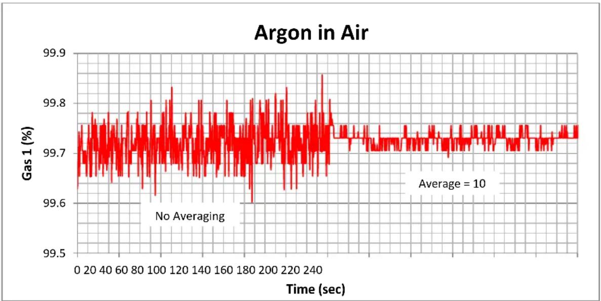
FIGURE 18: GAS CONCENTRATION WITH AND WITHOUT AVERAGING FOR ARGON AND AIR
Larger numbers of averages may be required to suppress interfering signals or recover low pressure signals in the presents of a lot of noise. This will slow the response time. You may need to experiment to find the best balance between stable answers and response time. See Averaging (page 74) for details.
REL to a Reference Gas
Using REL to a reference gas can help improve measurements by removing uncertainties in the temperature, pressure and other parameters. The procedure involves flowing a reference gas through the cell and then nulling the measured value to the expected value. This technique works well near the conditions where the REL was performed. Errors will increase as the operating conditions move the further away from the REL conditions.
The BGA244 is relatively insensitive to variations in temperature, pressure or flow. However large changes in the operating conditions will produce measurable changes in the measurements. The REL should be repeated whenever a significant change in the operating conditions occurs. This would include changes in temperature, pressure and flow or changing the gas used as the reference (new gas bottle).
A Reference Gas is usually:
■ One of the two gases in a binary mixture
■ An extremely well measured blend of the gases
■ The pure Gas for the Gas Purity Mode
The usual magnitude of the correction in a REL for a Reference Gas is a few percent or less. A larger than expected REL value may indicate that the gas you are using for a reference isn't as pure as expected.
It is best to perform a REL as close to the operating condition as possible. This means operating at the same pressure, flow rate and temperature. Note that the REL function refers to the value of the Primary Gas in the Binary Gas Analyzer Mode.
There are two techniques to purge the acoustic cell of all residual non-Reference gas.
- Flow the Reference Gas until the measurements have completely settled. This may take may take many minutes to remove any residual gas, especially at low flow rates.
- Evacuate the acoustic cell to vacuum prior to flowing the Reference Gas. This takes only a few seconds, but requires additional valves and pumps.

Caution: The accuracy of readings after setting a REL depends on how well the REL was performed. Be sure that the measurement has completely settled before performing the REL.
Procedure
Use one of the techniques to purge the acoustic cell to ensure that the pure Reference Gas is all that is in the acoustic cell.
Set the number of averages (N) between 20 and 60. Allow the reading to completely stabilize. Remember that it takes about N * 1.14 seconds for averaged measurements to settle. Refer to Averaging (page 74) for details.
Select (Use REL). Press [REL to 100%], [REL to 0%] or enter the
Return to the Home page. The reading should be very nearly the exact value that was selected on the REL page.
Binary Gas Analyzer vs Gas Purity Analyzer
Both the Binary Gas Analyzer and the Gas Purity Analyzer can be used to measure the purity of a gas. There are benefits for each analyzer depending on the gases being measured.
When to use the Binary Gas Analyzer
If you know the contaminating gas species you ordinarily want to use the Binary Gas Analyzer. It will accurately report the concentration of the contaminating gas species.
However if the contaminating gas is misidentified it will report the wrong concentration.
Example: The Binary Gas Analyzer is configured to measure Helium in Methane. It reports 95% Helium.
If the contaminating gas was actually air instead of Methane, the reported value would be incorrect. In this case the true concentration of Helium would be 97.3%
When to use the Gas Purity Analyzer
The Gas Purity Analyzer is most useful when you don't know the contaminating gas species. It reports the gas purity based only on the speed of sound of the gas. So you can determine that the gas isn't pure, but you do not know the concentration of the contaminating gas.
Example: The Gas Purity Analyzer is set to measure Nitrogen and reports ΔW/W = -1% .
This answer can be obtained from a variety of different contaminating gases, each with its own concentration. All you really know is that the contaminating gas is heavier than Nitrogen. The following table lists a few of the possible contaminating gases and their concentration required to make ΔW/W = -1% .
| Contaminating Gas | Concentration |
| Oxygen | 13.9% |
| Argon | 6.6% |
| Carbon Dioxide | 2.9% |
| Butane | 1% |
Converting Molar Fraction vs Mass Fraction
The ratio of the two gases can be reported as either a mole fraction or a mass fraction. These differ only by the atomic masses of the gases. Mole fraction is the ratio of the number of molecules of one gas relative to the total number of molecules in a volume. Mass fraction is the ratio of the mass of one gas relative to the total mass of the gas in the volume.
Mole fraction is commonly used in gas blending, while Mass fraction is used in monitoring combustion products. The BGA244 supports both methods.
The formula for converting from mole fraction to mass fraction is:
w 1 = (x 1 * M 1)/(x 1 * M 1) + (x 2 * M 2)
For converting mass fraction to mole fraction:
x 1 = (^ w 1 / _ M 1)(^ w 1 / _ M 1) + (^ w 2 / _ M 2)
Where w1, x1 and M1 are the mass fraction, mole fraction and Mass of the primary gas and w2, x2 and M2 are the mass fraction, mole fraction and Mass of the secondary gas.
Example: Determine the mass fraction of Nitrogen in air
For the simple 2 gas case (ignoring other gases), air made up of 78% Nitrogen molecules ( N2 ) and 22% Oxygen molecules ( O2 ). In this case, the mole fraction of Nitrogen in air is 78% or 0.78.
Mass Fraction N 2 = 0 . 7 8 * 2 8 . 0 1 3 4 8/(0 . 7 8 * 2 8 . 0 1 3 4 8) + (0 . 2 2 * 3 1 . 9 9 8 8) = 0. 7 5 6
Example: Determine the mole fraction of Hydrogen ( H2 ) for a mixture of 1 kg Hydrogen and 100 kg Carbon Dioxide (CO2).
Mole fraction of H2 = (1/1 0 1 2 . 0 1 5 8 8 / )/(1/1 0 1 / 2 . 0 1 5 8 8) + (1 0 0/1 0 1 / 4 4) 0 0 9 8 = 0. 1 7 9
Accuracy & Stability
The BGA244 makes two primary measurements: the speed of sound in the gas and the gas temperature. It combines those measurements with the gas pressure provided by the user and information about the gas species to report the ratio or purity of the gas. These measurements and data all have uncertainties that can lead to measurement errors.
The speed of sound for an ideal gas is given by the equation:
W = √ γRT/M
From this you can see that the speed of sound strongly depends on the gas temperature. Real gases have additional corrections that depend on the temperature, pressure and gas species.
Speed of Sound Measurement
Speed of sound of the gas can be resolved to <1 mm/s and is extremely stable over time and temperature. The stability and temperature coefficient are largely due to the crystal time base aging. These contribute an insignificant amount to the total measurement accuracy.
The speed of sound accuracy term ( ± 0.02%) does contribute to the total accuracy specification of the BGA244.
Temperature Measurement
The temperature of the gas can be resolved to 0.001 °C and is extremely stable over time. The stability is largely a function of the aging of the glass bead thermistor used to measure the gas temperature. This contributes an insignificant amount to the total measurement accuracy.
The temperature accuracy term ( ± 0.1\ °C ) does contribute to the total accuracy specification of the BGA244.
Pressure
The gas pressure is the only measurement provided by the user. While pressure does not affect the accuracy to the same extent as speed of sound or temperature, it is necessary to know the correct pressure to within 1 psi (6.9 kPa) to meet the specified accuracy.
Failure to enter the operating pressure or improperly configuring a pressure gauge will lead to measurement errors. Be certain you are operating with the appropriate pressure units (either absolute or gauge units). Refer to Pressure (page 98) for more details.
Gas Table Data
The BGA244 Factory Gas Table contains detailed information on nearly 500 gases gathered from a number of different sources as described in Appendix A: Factory Gas Table. As a general rule, commonly used gases have more accurate data available for than some of the more obscure gases. In very rare cases complete data may not exist for a gas. This can degrade accuracy when operating across a range of temperatures and pressures. Contact SRS if you have a question about a particular gas or gas mixture.
Using REL to Improve Accuracy
In some cases the REL feature can be used to null out the uncertainties in the speed of sound, temperature, pressure and gas data. Refer to REL to a Reference Gas (page 105) for more details about this procedure.
Estimated Accuracy
The Binary Gas Analyzer and Gas Purity Analyzer display the estimated accuracy for the measurement based on a temperature uncertainty of 0.1\ °C and a pressure uncertainty of 1 psi (6.9 kPa). The estimated accuracy does not use the REL value in its calculations.
Binary Gas Measurement Accuracy
In the Binary Gas Analysis mode, the gas concentration is determined by measuring the speed of sound of the gas in the cell and its temperature. The amount of each gas is calculated based on these measurements and their physical properties. At a given temperature T, the speed of sound is proportional to
√ (γ/M)
Since γ (the ratio of specific heats) only varies between 1 and 1.67, changes in the speed of sound are largely due to the change of mass, which can vary from 2 to around 200. Because of this, the BGA244 has the best resolution and accuracy when the difference in molar mass of the two gases is largest. After the molar mass, the next most influential parameter is γ (gamma). After these there are several non-ideal gas properties that cause additional shifts. The BGA244 accounts for all of these factors.
The best measurement sensitivity occurs when measuring a small amount of a heavy gas in a lighter gas. Absolute accuracies at the 10 ppm level are possible for a small amount of a heavier gas with a carrier of Helium or Hydrogen.
Example: Measuring the ratio of 1% SF6 (mass 146) in Helium (mass 4) gives an estimated accuracy of 0.0007% (7 ppm).
The REL mode can be used to cancel out the some of the measurement uncertainties. With this relative accuracies of <100 ppm level are achievable for many gas mixtures.
Poor Sensitivity
The measurement sensitivity suffers for mixtures where both gases have similar speeds of sound. This leads to somewhat poorer estimated accuracy.
Example: Nitrogen (mass 28) and oxygen (mass 32) have similar speeds of sound (around 349 and 326 m/s). At an 80%/20% ratio, the estimated accuracy is 0.24%.
Problem Mixtures
Other gas mixtures can be even more problematic. For certain gas combinations there are two different gas ratios with the same speed of sound over a portion of their range. Both of these ratios are equally valid as far as the BGA244 can determine. The BGA244 detects if this occurs and reports both solutions (Two Solutions) as described in Screen Messages (page 51).
These mixtures can be measured with some restrictions. For a portion of their range there is only the single molar ratio value. Or if the approximate ratio is known, the larger or smaller solution can be selected.
Problem mixtures can occur for gases with similar molar masses and different molecular types (monatomic, diatomic or polyatomic). Use the Accuracy Calculator in BGAMon to determine if this problem exists for your gas combination, pressure and temperature. In some cases this effect can be minimized by operating at a different pressure or temperature.
Certain problem mixtures exist for all binary gas analyzers. They may be more visible with the BGA244 because it supports many thousands of different gas combinations and concentrations.
Example: A common mixture that exhibits this behavior is Argon (mass 36, γ = 1.67 ) in Oxygen (mass 32, γ = 1.45 ). At NTP there is a single solution reported for 0 - 43.5% , but two solutions above that.
These problem mixtures can also affect Physical Measurements accuracy, albeit to a far lesser extent. Calibration factors in the BGA244 depend on properties of gases in the resonant cell. These will be incorrect if the “wrong” concentration is used. However this affect is extremely small. A typical worst case error is approximately 30 ppm
Gas Purity Measurement Accuracy
In the Gas Purity Analysis mode the measured speed of sound of the gas in the cell is compared with expected speed of sound at that temperature and pressure. This measurement is sensitive to small amounts of an unknown contaminating gas. However the magnitude of the reported value depends on the species of the contaminating gas. Gas Purity measurements are most sensitive when the contaminating gas(es) have a much higher or lower speed of sound. Gases with similar speeds of sound are problematic. Higher speeds of sound are normally associated with lighter gases, while slower speeds of sound are associated with heavier gases.
Example:
1% of He (a lighter gas) in N2 give a purity measurement of +0.491% 1% of SF6 (a heavier gas) in N2 gives a purity measurement of -2.482% 1% of O2 (similar mass) in N2 gives a purity measurement of -0.073%
This problem becomes more difficult when dealing with multiple contaminating gases. As a rule, if the reading is positive the combined contaminants are lighter gases; if negative, the contaminants are usually heavier. However it is possible for the contaminant to be a mixture of both heavier and lighter gases. In this case measurements can be unpredictable.
Long Term Stability
Measurements made by the BGA244 are extremely stable, assuming no dramatic changes in the operating conditions. Long term aging is on the order of 10 ppm/year. This is primarily due to aging in the crystal time base and the glass bead thermistors.
Short term drift is usually caused by a change in the gases being measured brought about by leakage or outgassing of the Kapton transducers.
High Purity Use
Certain applications are extremely sensitive to any contamination. These may involve low flow rates, sensitivity to contamination, operating below atmospheric pressure or a combination of these. The following section provides some guidelines to help minimize contamination in sensitive systems. For the most stringent applications SRS recommends using the BGA244HP.
Fittings and tubing
Metal tubing and all metal seals should be used. Avoid elastomeric seals as they are porous and prone to outgassing. VCR fittings are recommended for applications operating below atmospheric pressure.
Leak Testing
The BGA244HP is Helium leak tested at the factory, while the standard BGA244 is not. Leak tests are commonly performed on systems after any significant changes are made to the gas manifold or fittings. Depending on the application either outbound or inbound leak testing may be appropriate.
Dead Volumes
There are several small volumes in the BGA244 that are poorly vented to the cell. These total about 1 cc and vent to the cell by diffusion through fairly low conductance paths.
For normal operation these volumes contain the same gas as the rest of the cell and have no effect on measurements. However if the gas species has changed significantly, the gas in these volumes will gradually diffuse into the cell over a few minutes. The diffusion occurs faster for lighter gases than for heavy gases. For low flow rates this may introduce a small error for the first few minutes after the gas species has changed.
If this presents a problem, the cell can be briefly evacuated under vacuum to vent these volumes. Otherwise flow gas for a few minutes to allow these volumes to diffuse into the cell.
Outgassing
Outgassing is only a concern when a cell has been exposed to moist air, solvents, or if the gas species in the cell have changed. Normally it can only be detectable at very low flow rates and will diminish over time. To accelerate outgassing, follow the Degas procedure later in this section.
The primary source of outgassing in the BGA244 is the Kapton acoustic transducers. While Kapton has excellent resistance to nearly all chemicals, it is hydrophilic and porous to some gases. Substances that are readily absorbed by Kapton include water, alcohols and many solvents (generally polar molecules).
There is about 2.9 in2 (18.5 cm 2 ) of 1 mil (0.025 mm) thick Kapton in the two acoustic transducers. If fully saturated, they can absorb around 2.7 g of water. At NTP this becomes about 3.3 cc of water vapor. Similar amounts of other polar molecules will also be absorbed.
Kapton is also somewhat porous to many gases. Gases present in the cell will diffuse into the transducers. If the gas is changed or the cell is put under a vacuum, this gas will gradually diffuse out. This will have no effect if the gas species hasn't changed, but it can be detected if the cell is filled with a different gas or under vacuum.
Does outgassing matter? In most cases it will be undetectable. For a fully saturated membrane at room temperature, the outgassing rate of Argon, Nitrogen or water vapor starts at about 1 × 10⁻⁴ sccs and decreases over time. For a 500 sccm flow this corresponds to a contamination of about 12 ppm. However for very slow (or zero) flow rates it can become a significant source of contamination.
The gases absorbed by the Kapton can be largely removed using the following Degas procedure. This will reduce the effect of outgassing from the Kapton to below 0.1 ppm for the same 500 sccm flow.
Always minimize exposure to the atmosphere or other contaminants to reduce the amount absorbed. Fill the cell with a dry gas and cap it off if not in use. Follow the Degas procedure if exposure has occurred or different gasses are being used.
Degas
The Degas and Block Heaters can be used to dramatically reduce the outgassing rate of the Kapton transducers. This procedure is optimally done under vacuum where the outgas rate can be monitored. If necessary it can also be done while flowing a dry gas through the cell for an extended period of time.
Degas requires an external +24 V power supply rated for at least 1A. If degas is being done under vacuum, a residual gas analyzer, ion gauge or other suitable vacuum gauge can be used to track the outgassing rate until it reaches an acceptable level. The SRS RGA100/200/300 and IGC100 are well suited for this. Refer to Heaters (page 77) for details on operating the heaters.
Under Vacuum
Set the block heaters to 70 °C and turn on Degas. The initial outgassing rate of the Kapton transducers will be around 1 × 10⁻⁴ sccs for water vapor, Argon or Nitrogen. After the heaters are first turned on, the rate will initially increase. Typically the rate should be around 5 × 10⁻⁵ sccs after a few minutes and then decrease exponentially over time.
Run degas until the outgas rate has dropped to around 1 × 10⁻⁶ sccs or whatever level is acceptable if the outgas rate is being monitored. Otherwise run for at least 3 hours.
When complete, turn off Degas and the Block Heater. Remember that the BGA244 cannot make gas measurements under vacuum. Fill the cell with a dry gas and cap it off if not in use.
While Flowing Gas
This procedure can also be performed while flowing a dry gas through the BGA244. It may take longer to reach the same outgas rate since the Kapton transducers are cooled by the flowing gas. Ideally the dry gas should be one of the gases being used in operation so a different gas species isn't absorbed into the membrane.
Set the block heaters to 70\ °C and turn on Degas. Flow at least 10 sccm of the dry gas through the BGA244. Run Degas for at least 3 hours. This should reduce the outgas rate to around 1×10⁻⁶ sccs.
When Degassing is completed, turn off Degas and the Block Heater. Remember that the BGA244 cannot make gas measurements when Degas is on. Fill the cell with a dry gas and cap it off if not in use.
User Gases
The BGA244 Factory Gas Table contains nearly 500 different gases. However there are many more gases that can be measured, including mixtures or blended gases. Blended gases are made up of two or more single species gases. The BGA244 supports a User Gas Table that allows a nearly unlimited number of new gases to be added by the end user.
Gases in the BGA244s Factory Gas Table have detailed information about how a gas behaves over a wide temperature and pressure range, as well as how it interacts with any other gas. However gases don't always need to be specified this completely to make accurate measurements, especially at fairly constant temperatures and pressures.
User Gases are modeled using the ideal gas law. This is a reasonable approximation of the behavior of many gases, especially at constant temperature and pressure. However it can lead to errors when operating over wide ranges of temperature, pressure or ratios. But remember that repeatability is often more important than accuracy. As long as you operate at a similar temperature and pressure, the measured values won't change much.
Contact SRS if you are unable to obtain adequate results with a User Gas. In some cases we are able to create a complete model of a gas and add it to the Factory Gas Table.
Factory Gas Table
The Factory Gas Table contains a comprehensive list of data for each gas, including names, formula, molar mass and various thermodynamic properties. This information allows accurate measurements to be made on a wide variety of gases over the entire operating range of the BGA244.
See Appendix A (Gas Table) for a detailed explanation of all of the terms contained in the Factory Gas Table and their effects on measurements.
User Gas Table
The User Gas Table is used to store data on gases that aren't available in the Factory Gas Table. This information is stored using the BGAMon Software. The following parameters can be entered for User gases: Name, molar mass and γ (ratio of specific heats).
Selecting a User Gas
User gases show up in gas selection searches as "User/Gas Name". See Selecting Gases in the Operations Guide for more information.
User Gas Parameters
User gases must have a name, molar mass and a single thermodynamic parameter γ (gamma). The name is used when selecting the gas and to display on the Home page. The molar mass is the atomic weight of the molecules multiplied by their concentration. γ is ratio of specific heats.
The following section describes the technique for adding a User Gas to the BGA244. Most User Gases added will be blends of other gases since the BGA244 Factory Gas Table contain nearly every non-blended gas.
Mass
Finding the mass of the gas is fairly simple. For a single species gas, it's just the molecular mass in AMUs (atomic mass units).
To calculate the molar mass of a blended gas, take the molar (mole) fraction of each gas times its mass. Assuming MF1 and MF2 are the mole fractions of each gas.
mass = (mass 1 × MF 1) + (mass 2 × MF 2)
This equation can be extended to all the gases that make up the blend.
y
γ (gamma) is the ratio of specific heats or heat capacity ratio in a gas. γ is a unitless quantity that can be expressed in terms of Cp (heat capacity at constant pressure) and Cv (heat capacity at constant volume) or Cp and R (the ideal gas constant).
γ = Cp/Cv = Cp/Cp - R
γ (gamma) and Cp values for many gases can be found in literature or on line. Both Cp and R can be expressed in different units so make sure that you use the same units for both when calculating γ .
The following rules are generally true for single species gases at room temperature and near atmospheric pressure:
■ Monoatomic gases γ ≈ 1.66
■ Diatomic gases γ ≈ 1.4
■ Polyatomic gases γ ≈ 1.05 - 1.25
Try to obtain values for γ at or near the temperature and pressure the BGA244 will be operating for best accuracy.
Since the Factory Gas Table contains nearly all of the monatomic and diatomic gases most added gases are either polyatomic or blends. γ varies from 1.1 – 1.2 for most polyatomic gases.
Hint: If you can't find a value for γ for the gas you are adding, use a value from a similar gas.
Determining γ is a bit more complicated for blended gases. Assuming that
- γ 1 is for the gas 1, γ 2 is for gas 2 and γb is for the blend
■ MF1 and MF2 are the mole fractions of each gas.
Then
γb/γb - 1 = (γ 1/γ 1 - 1 × MF 1 ) + (γ 2/γ 2 - 1 × MF 2 )
This equation can be extended to all the gases that make up the blend.
Adding a User Gas with BGAMon
User gases can be added using BGAMon See Chapter 5: BGAMon for information on installing and using the BGAMon software.
Click [Page] [Gas Table] to access the Gas Selection page. Press [Add Gas] in the User Gas Table area to open the Add User Gas dialog box. Enter the name, molar mass and γ (ratio of specific heats). Click [OK] to save the new gas to the BGA244 User Gas Table.
User Gases are selected the same way as gases from the Factory Gas Table. They are identified by "USER/gas name".

Adding a User Gas over a Computer Interface
User Gases can also be added over the Remote Interface using the AUSR command. The arguments for the AUSR command are the molar mass, gamma and name.
Example
An approximation for air is 79% N2 and 21% O2 . This has a molar mass of 28.86 and a gamma of 1.4. So the command to enter this over the remote interface is:
AUSR 28.86,1.4,Air
User Gases are selected using the same commands as Factory Gases. Instead of using the CAS #, use the string: "User/gas name".
Adding Gases
Example: Adding a Single Species Gas (Argon)
To add a gas, you need the three previously mentioned items: a name, molar mass and γ . For this example we will add a simple model for Argon to the User Gas Table.
Name = Argon
■ Molar Mass = 39.95 (same as the atomic mass)
■ γ = 1.66 (Argon is monatomic)
Example: Adding a Blended Gas (Air)
Blended gases are made up from two or more single species gases. The molar mass and γ must be calculated based on the ratio of the gases in the blend.
The most familiar blended gas is air. As a commercial product, air is usually considered to be 79% Nitrogen and 21% Oxygen.
To find the molar mass of the gas, take the mole fraction of each gas times its mass.
| Gas | Mol Fraction | Mol Mass | Fractional Mass |
| N2 | 0.79 | 28.02 | 22.14 |
| O2 | 0.21 | 32.00 | 6.72 |
| Sum | 28.86 |
Note that the molar mass is slightly different than the value from the Factory Gas Table. This is because Air in the Factory Gas Table is atmospheric air (78.09% N2, 20.95% O2, 0.93% Ar). The extra mass of Argon (39.95) increases the total mass slightly. However since it is such a small fraction of the total it has no real effect on the thermodynamic data ( γ ).
Name = Air
■ Molar Mass = 28.86
■ γ = 1.4 (both gases are diatomic)
Example: Adding a Blended Gas (Heliox)
Another common blended gas is Heliox 80:20 (He:O 2 ). The calculations are a little more complicated than air since Helium is monatomic and Oxygen is diatomic.
To find the molar mass of the gas, take the mole fraction of each gas times its mass.
| Gas | Mol Fraction | Mol Mass | Fractional Mass |
| He | 0.80 | 4.03 | 3.22 |
| O2 | 0.20 | 32.00 | 6.40 |
| Sum | 9.62 |
γ mixes as the mole fraction of the two gases.
To find γ for the blend, apply γ and the mole fraction of each gas to the formula above.
| Gas | Mol Fraction | γ | Blend γ |
| He | 0.80 | 1.66 | |
| O2 | 0.20 | 1.40 | |
| 1.58 |
Name = Heliox 80-20
■ Molar Mass = 9.62
■ γ = 1.58 (calculated above)
Operating with User Gases
Typically there will be larger pressure and temperature dependent errors associated with User entered gases, since they are not specified as thoroughly as factory gases. Try to operate at a fairly constant temperature and pressure to avoid these errors.
Changes in gas parameters with temperature and pressure may create significant errors in some cases. But there are plenty of situations where they will have an insignificant effect.
If the User gas is used as a dopant to a much lighter factory gas, the differences in mass may overwhelm any small errors in the gas model.
- The thermodynamic properties of the user gas may not vary much over the operating pressure and temperature range.
- Many processes depend more on changes in values rather than the actual value. REL can be used to establish a baseline and variations can be tracked from that value.
If possible, find values for γ at or near the operating temperature and pressure for best accuracy. Operate at a stable temperature. The block heater is an easy way to achieve this.
Invalid Gas Message
Stored settings (in the BGA244) and stored configuration (on BGAMon) can reference User Gases. An error is created if a setting or configuration tries to recall a non-existent User Gas. If this occurs, the screen message “Invalid Gas” is displayed and an error is reported. To correct this first select a different gas, then re-add the User Gas and select it.
Using REL with User Gases
In some cases the BGA244 will operate at high concentrations of the User gas. In this case you can REL to the User gas as a Reference. Follow the procedure REL to a Reference Gas described earlier in this chapter.
Chapter 5: BGAMon
BGAMon is a Windows based program for controlling the BGA244. It can:
■ Display and configure all instrument parameters
■ Save and recall instrument configurations to disk
■ Perform data acquisition
- Add User Gases
■ Update the BGA244 firmware
BGAMon is extremely useful to configure units with accessory BGA-M installed (metal cover) or units installed in remote or inaccessible locations.
This chapter provides details on using BGAMon but does not describe operation of the BGA244 in detail. See Chapter 3: Operation Guide for specifics on operating the BGA244.
The following conventions are used to refer to controls and messages for BGAMon. In general bold text is used to indicate a control or reading on BGAMon
- [Button] refers to a button that can be clicked to execute a function.
indicates that a value needs to be entered where "Entry" is the name of the parameter. Use the keyboard to enter the value. If the entered value is out of range, it will be ignored. indicates that a value needs to be selected from a list where "Entry ↓" is the name of the list. Pressing the key will open a drop down list of possible selections. [Press] the desired selections to choose it. - Choice indicates a "radio button" that is used to select one of a number of possible choices. Press the circle to select that choice and de-select all other choices.
- Choice indicates a check box that is used to enable a choice. Unlike Radio Buttons, you can select any or all of check boxes as needed.
- (Here/There) refers to a location accessed from the Menu bar. For example to reach (Page/Pressure) you would first click the Page menu and select Pressure.
- {Message} refers to a popup Windows dialog box. This box will contain buttons and possible other controls. This box must be closed to return to the normal operation of BGAMon.
Installation
This section describes how to install and begin using BGAMon. BGAMon communicates with the BGA244 over USB. It requires a USB driver be installed to operate.
Drivers
BGAMon requires that the FTDI D2XX USB driver has been installed on the computer for proper operation.
Note: Windows may check for a new driver each time a different BGA244 is connected to the computer.
The first time the BGA244 is connected to the USB port of a computer running Microsoft Windows, you will likely be prompted with a “New Hardware Found” message and an invitation to search for the USB Driver. There are two USB drivers for the device (VCP and D2XX drivers). Depending on the version and configuration, Windows may either automatically install the drivers or prompt you to search for them. Allow Windows to install the drivers. Occasionally only a single driver will install. In some cases disconnecting and reconnecting the BGA244 will cause the second driver to load correctly.
If the drivers do not load successfully see Appendix E for details on manually installing the drivers.
Note: In some circumstances it may take a long time to load the drivers (up to 30 minutes or more). This is primarily caused by high demand on the Microsoft Update website. If possible try again later where there will (hopefully) be less traffic. Otherwise use the manual installation procedure described in Appendix E (page 271).
Downloading BGAMon
The BGAMon Installer can be found on the thinksrs.com website. There is also a readme.txt file that contains information on the latest version of BGAMon. Use the following steps to download, extract and install BGAMon to your computer.
- Go www.thinksrs.com . Navigate to the Binary Gas Analyzer page.
- Click on the BGAMon Software link under "Downloads". Save the BGAMon zipped file to your computer.
- Go to the folder where the file was downloaded. Double click on the file to extract the BGAMon Installer.
- Double click the BGAMon Installer icon to launch the BGAMon Installer. Follow the installer instructions.
After installation the BGAMon icon should appear on your desktop. Double click it to start BGAMon.
BGAMon Quick Start
Use the following procedure to begin using BGAMon to control the BGA244. If you encounter problems with any of the following steps see Troubleshooting BGAMon (page 144) for further instructions.
Connect the BGA244 to the computer's USB port using a USB Type A to USB Type B cable. If you plan power the BGA244 using a 24 VDC power supply, connect it prior to connecting the USB port to the computer. Be sure the USB power supply and cable are sufficient to operate the BGA244 if using USB for power. See Power (page 22) for details on appropriate power supply and cabling.
Double click on the BGAMon icon to start the program. Wait a few seconds after the BGA244 is plugged in so Windows can detect that it's connected. Then click [Connect to Device] on the BGAMon System area. The message adjacent the button should change from *NOT CONNECTED* to *CONNECTED*.
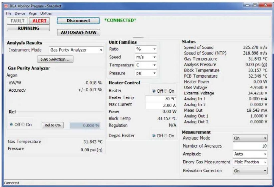
BGAMon starts on the Snapshot page. Here you can see the primary measurements and settings for the BGA244. Assuming the BGA244 has come from the factory and the gas port caps haven't been removed, it should display < 0.1% ΔW / W for Argon.
Using BGAMon
The operating state of BGAMon is based on the connected BGA244. Changes made to either the BGA244 or BGAMon are automatically transferred to the other. Any changes made to BGAMon when not connected are lost as soon as the BGA244 is connected.
The BGAMon screen consists of four main areas: the Menu bar, System area, Instrument page and Status bar.
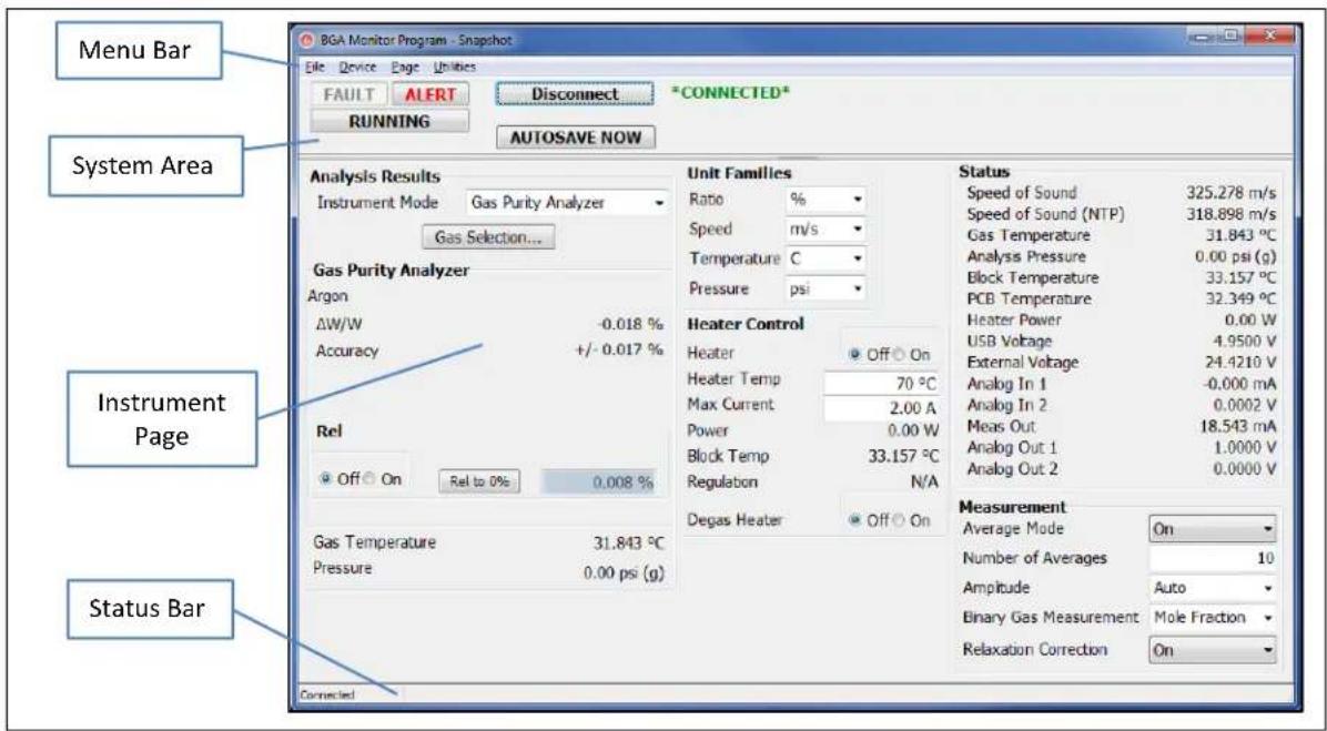
FIGURE 20: BGAMON LAYOUT
Menu Bar
The Menu bar contains the navigation functions to access the different parts of BGAMon. These include File, Device Page and Utilities.
File
The File menu accesses the Load and Save Configuration pages. See Loading and Saving Configurations (page 142) for details.
Device
Detect Device can be used to see if the BGA244 USB driver is properly installed and the BGA244 has been detected by Windows. See Troubleshooting BGAMon (page 144) for details.
Page
The BGAMon instrument pages are accessed from this Menu. These include:
■ Snapshot: Overview of most of the instrument settings and measurements
■ Analog Input/Output: Configuration for the analog inputs and outputs
■ Pressure: Configuration for pressure sensing and entry
■ Limits: Configuration for all Limit values
■ Events: Configuration and control of the Event Relays
- Strip Chart: Access and display for the BGAMon data acquisition
Gas Selection: Gas Table and gas selection controls
■ Faults/Alerts: Monitor and control for all active Fault and Alert conditions
■ Computer I/O: Configuration for RS-232 and RS-422 interfaces
■ Store/Recall: Store and Recall BGA244 settings to flash memory
Utilities
Utilities are functions that aren't part of the normal operation of BGAMon.
■ See Updating Firmware (page 143) for details on updating the BGA244 firmware.
■ See Utility Mode for information on the Utility Mode.
System Area
This area contains controls and indicators that are visible for all the instrument pages.
Fault
[FAULT] is a dual purpose control. First it indicates that a fault has occurred by turning red. Clicking on it when active opens the Faults/Alerts page for additional information about the active faults.
Alert
[ALERT] is also a dual purpose control. It indicates that an alert has occurred and clicking on it when active also opens the Faults/Alerts page for additional information about the active alerts.
Running
The [RUNNING|STOPPED] key acts the same as the [RUN|STOP] key on the BGA244 setup page. When [STOPPED] is selected most measurements on the BGA244 are halted. See Run|Stop (page 58) for details.
Screen Messages
Screen Messages may appear under the Fault and Alert indicator buttons. These are the same messages that appear on the BGA244 Home pages. See Screen Messages (page 50) for more information.
Connect or Disconnect
The [Connect] or [Disconnect] buttons connects or disconnects the BGAMon software with the BGA244. The current state is indicated by the *CONNECTED* or *DISCONNECTED* message that appears next to the button.
See Troubleshooting BGAMon (page 144) for further instructions if a {Device Not Found} or {Unable to open BGA Device} message box appears.
Autosave
Click [AUTOSAVE NOW] to immediately save the BGA244 configuration to flash. Autosave ordinarily will not occur until about 30 seconds after the last change to the BGA244 configuration occurs. Recent changes may not be saved if power is removed prior to Autosave occurring.
Instrument Page
The Instrument Page is selected from the Page Menu Bar. This section displays the BGA244 measurements and configuration. See the Instrument Pages in the following section for details on the different pages.
Status Bar
The Status Bar displays the operating state of BGAMon.
Instrument Pages
The Instrument pages show the operation of the BGA244. Most of the settings and measurements in BGAMon are the same as the BGA244 GUI. They are organized a bit differently to take advantage of the larger screen. The BGAMon functions are described in terms of their counterparts in the BGA244 GUI. See Chapter 3: Operations Guide for details on the use and meaning of the different controls. One feature that is unique to BGAMon is the Strip Chart. This can acquire, graph and store BGA244 measurements over intervals ranging from seconds to days.
Snapshot
Snapshot is an overview of the key measurements and settings of the BGA244. It combines the functions of a number of different pages including the Home page, Setup page and a number of Control Panel pages.

This section selects the instrument mode, the measured gas and REL. It reports the measured value, estimated accuracy, gas temperature and pressure. Most of the reported values and controls depend on the selected Instrument Mode. See the Home page for each Instrument Mode in Chapter 3 for further details.
Select Binary Gas Analyzer, Gas Purity Analyzer or Physical Measurements using
Click [Gas Selection] to jump to the Gas Selection page to select gases.
The Measured Value and Estimated Accuracy are determined by the Instrument Mode, selected gases and measured value. The Gas Temperature and Analysis Pressure are displayed at the bottom of this section.
User Speed of Sound and REL are specific to particular Instrument Modes. See the Home page for each Instrument Mode in Chapter 3 for details.
Unit Families
These are the settings from the Units page in the Control Panel. See Units (page 73) for details.
Heater Control
These are the settings and measurements from the Heaters page in the Control Panel. See Heater (page 77) for details.
Status
These are the measured values from the Status page in the Control Panel. See Status (page 76) for details.
Measurement
These are the settings from the Measurement page in the Control Panel. See Measurement (page 74) for details.
Analog I/O
The Analog I/O page combines the separate Analog Input and Output pages from the BGA244 Control Panel. See Analog I/O (page 80) for details.

FIGURE 22: ANALOG I/O PAGE
Note: The Analog Inputs can be configured from either the Pressure page or Analog I/O page. Changes made in one location will be reflected in the other location.
Pressure
The Pressure page combines all of the separate Pressure pages from BGA244 Setup menu. See Pressure (page 63) for details.
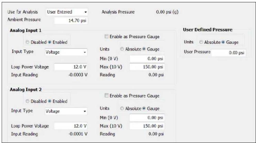
FIGURE 23: PRESSURE PAGE
Note: The Analog Inputs can be configured from either the Pressure page or Analog I/O page. Changes made in one location will be reflected in the other location.
Limits
The Limits page combines the limit settings from all of the separate graphs that have limits. This includes limits for the Binary Gas Analyzer, Gas Purity Analyzer and Physical Measurements (all Limits, page 54), plus the Pressure Meters (Pressure page 63) and Temperature Meter (Temperature page 66).

FIGURE 24: LIMITS PAGE
Events
The Events page combines the BGA244 Event 1 and Event 2 Relay Configuration pages. See Event Relay 1 & 2 (page 55) for details.
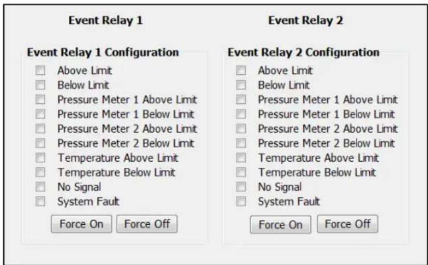
FIGURE 25: EVENTS PAGE
Strip Chart
The BGAMon Strip Chart can acquire, plot, print and export measurements from the BGA244 as a function of time. The following measurements can be captured, printed and exported to a file.
■ Primary and Secondary Gas Concentrations
Gas Purity
■ Measured Speed of Sound and Speed of Sound normalized to NPT
Gas Temperature
■ Heater Power
■ Pressures (User, Pressure Gauge 1 & 2, Analysis Pressure)
■ Analog Input 1 and 2

FIGURE 26: STRIP CHART PAGE
Measurements
BGAMon continuously records 13 different measurements when connected to the BGA244. All of the data taken is stored regardless of what is displayed on the chart. Measurements are started when BGAMon is connected to the BGA244. They are stopped if BGAMon is disconnected from the BGA244. Measurements are made at the BGA244's measurement rate (\~4 Hz) and are time stamped by the BGA244 to eliminate any time uncertainty from Windows.

Note: Data is not saved if program is closed. Either print the graph or export the data to a file to save it after the program is closed.
Click [Clear Data] to clear the existing strip chart data and start collecting new data. Note that all previous data is permanently lost when this button is clicked.
Measurements for the Binary Gas Analyzer, Gas Purity Analyzer and Physical Measurements are always being captured, regardless of which instrument mode is selected.
Tip: Ordinarily BGA and GPA measurements aren't displayed at the same time. One case where it may be useful to display both is when dealing with nearly pure gases.
Certain measurements can be disabled in the BGA244. These include Heater Power, User Entered Pressure, Pressure Meters 1 & 2 and Analog Inputs 1 & 2. Disabled measurements will hold their last valid reading. That valid reading will be zero (0) if they haven't been enabled since the BGA244 was connected.
Units for the measurements are fixed to the values listed below. They do not reflect the Global units set on the BGA244.
■ BGA Primary & Secondary Concentration (%): Binary Gas Analyzer Primary & Secondary Gas concentrations reported in %.
■ GPA Delta Speed (frac): Gas Purity Analyzer ΔW/W reported in fraction.
■ PHYS Speed of Sound (Meas) (m/s): Physical Measurements Measured Speed of Sound reported in m/s.
■ PHYS Speed of Sound (NTP) (m/s): Physical Measurements NTP Speed of Sound reported in m/s.
Gas Temp (C): Gas Temperature reported in °C.
■ Heater Power (W): Heater Power reported in Watts. Value is 0 if disabled.
- User Entered Press. (psi): User Entered Pressure reported in psi. This will read in either absolute or gauge units depending on the BGA244 User Pressure units.
- Press. Gauge 1|2 (psi): Value from Pressure Gauge 1|2 reported in psi. This value depends on the BGA244 Gauge 1|2 configuration parameters. Value is 0 if disabled.
■ Analysis Press. (psi): Value of the selected Analysis Pressure. This value depends on the BGA244 analysis pressure setting and the parameters associated with it.
- Analog In 1|2 (V or mA): Value of Analog Input 1 reported in either V or mA. The units depend on whether voltage or current input is selected on the BGA244. Value is 0 if disabled.
Graph
Click the desired Measurement check box to display it on the Strip Chart. Traces are assigned colors in the order they are added to the chart. Note that measurements for File Export are selected on the Export page independent of the graph.
Every point acquired is displayed on the strip chart for time scales of 30 seconds per division or less. For time scales of 1 minute or greater there are more data points than pixels available on the strip chart. In this case either the mean or the minimum, mean and maximum values can be displayed for each time point. The mean value is plotted in a darker color than the minimum and maximum values. Right click on the trace to open the {Show Min/Max} dialog box. Check or uncheck the box to enable or disable the Min/Max feature.


The [Chart Title] can be entered to help identify printed graphs.
Time Axis
The Time Axis operates in two different modes. Use [Display Mode ↓] to select between the Scroll and Fixed modes.
The Scroll mode displays the last "n" points of data taken. The Time Axis scrolls left as needed to show these points. Use the Time per Division display to show more or less data. This mode is commonly used while collecting data as it lets you view trends over either long or short time intervals.
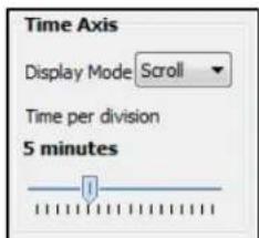
The Time Axis is static for the Fixed mode. Use the Time per Division control to zoom about the cursor position. The left and right keyboard arrows can be used to pan the time axis data when zoomed in.
The Time Axis can be set between 5 sec to 50 days per division using the slider control. This enables BGAMon to display data over a wide range of time scales.
Y Axis
Each Measurement has a separate Y Axis that can be scaled independently. Each scale can be set using the

[Autoscale Now] scales the minimum and maximum values at the moment it was pressed. □ Always Autoscale Y Axis will automatically rescale the display for each value acquired.
While many traces can be simultaneously displayed, only a single Y axis can be active at a given time. The active Y axis is indicated by the selected measurement and by the Y axis unit's label.
Cursor
The cursor reports of the value of the active trace (the selected Y axis) at the cursor Time axis value. Use the (computer) mouse to drag the cursor along the time axis to the desired location. If Show Min/Max is active the cursor reports the Mean value.

Printing
Click [Print] to open the Strip Chart Print Preview dialog box. From here you can select and setup installed printers and adjust the appearance of the strip chart prior to printing.
Select and configure the desired printer from Print Preview. Set the Orientation and Margins to scale the strip chart to the desired size. Use the Detail slider to adjust the font size and grid spacing. Click [Print] to send the preview graph to the printer when you are satisfied with the print preview.
Note: The print preview dialog box will not automatically close after [Print] is clicked. Click [Close] after the graph has been printed to close the window.

FIGURE 27: PRINT PREVIEW WINDOW
Export
Click [Export] to open the Strip Chart Export dialog box. From here you can select the measurements and time scale of the exported data. Data can be exported in either CSV (comma separated value) or TXT (text) format.
Select the measurements to be exported under Measurements or check Select All. Check Save Raw Data if you want to save every point of the acquired. Otherwise select the time interval between saved points using the Measurement Time Interval slider. Set the Start and End range using the either the Range sliders or
Tip: Raw Data export files can be really big if you are saving anything longer than about an hours' worth of data. It normally works better to use a longer measurement time interval if you want to save more than 30 minutes of data.
Include Instrument Information prepends the time and date the file was saved, the unit serial number, firmware build number/date and calibration date. Additional Comments can also be added to the instrument information to document the data.
After the data to be saved has been properly configured, click [OK] to open the Windows Save As dialog box and save the file.

FIGURE 28: EXPORT WINDOW
Gas Selection
The measured gases used by the BGA244 are chosen on the Gas Selection page. The page includes a searchable copy of the Factory Gas table, an editable User Gas Table and controls to select the measured gases. See Selecting Gases (page 58) for specific details on setting gases.
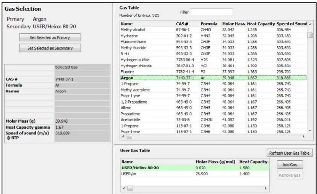
FIGURE 29: GAS SELECTION PAGE
Factory Gas Table
The Factory Gas Table is automatically loaded when BGAMon connects to the BGA244. Gases can be sorted by name, CAS #, chemical formula, molar mass, heat capacity (γ) or speed of sound (NTP).
To scroll through the gas table use the slider bar or up and down arrow keys. Use [Filter] to search the entire gas table for matching entries.
User Gas Table
The User Gas Table is also loaded when the BGA244 connects to BGAMon. The User Gas Table is empty unless gases have been previously added by the user. See Adding and Removing User Gases below for details.
Set Gases
First select the desired gas from either the Factory or User Gas Tables by clicking on it. Data for the selected gas is displayed to the left on the Gas Table.
Click [Set Selected as Primary] or [Set Selected as Secondary] to send the selected gas to the BGA244 to be measured. The selected Primary and Secondary gases are highlighted in green in the gas tables.
Adding and Removing User Gases
Gases can be added or removed from the User Gas Table. See User Gases (page 116) in Chapter 4 for instructions on determining the different parameters required for User Gases.
To add a User gas click [Add Gas] to open the Add User Defined Gas dialog box. Enter the
Click [OK] to save the User Gas table to the BGA244.

To remove a User Gas, first select it and then click [Remove Gas] to remove it from the User Gas Table. Note that gases that are selected as the Primary and Secondary gases (highlighted in green) cannot be deleted. To delete one of these gases you must first select another primary or secondary gas and then delete it.

Note: If a User Gas is deleted it cannot be retrieved.
[Refresh User Gas Table] will reload the User Gas Table from the BGA244. The User Gas Table is loaded when BGAMon is first started. However if a User Gas is added over the computer interface while BGAMon is running the Gas Table would need to be refreshed to display the new gas.
Invalid Gas Message
Stored settings (in the BGA244) and stored configuration (on BGAMon) can reference a nonexistent User Gas. This is indicated by the screen message "Invalid Gas" and a reported error. If this occurs, select a different gas. If the User gas had been inadvertently deleted, re-enter the data and then select it.
Faults/Alerts
The Faults/Alerts page combines the Faults page and the Alerts page from the BGA244 Control panel. See Faults (page 84) and Alerts (page 86) in Chapter 3 for details.

FIGURE 30: FAULT/ALERT PAGE
Active Alerts are displayed as buttons. Click [Alert] to open an Alert Action dialog box. This allows the Alert to be cleared or disabled. See Alerts Action (page 88) for information on this and the [Enable All Alerts] button.

Computer I/O
The Computer I/O page combines the RS-232 page and RS-422 page from the BGA244 Control Panel. See Computer I/O (page 78) for details.
Note that the USB page and the RS-232 and RS-422 Transmit and Receive buffer pages are not accessible from BGAMon.

FIGURE 31: COMPUTER I/O PAGE
Store / Recall
The Store / Recall page combines the all of the Store, Recall and Erase pages from BGA244 Setup page. See Store/Recall (page 66) for details.
Store / Recall Instrument Settings
| 0 | DEFAULT |
| 1 | HELIUM |
| 2 | ARGON |
| 3 | NITROGEN |
| 4 | CO2 H2 |
| 5 | *EMPTY* |
| 6 | *EMPTY* |
| 7 | *EMPTY* |
| 8 | *EMPTY* |
| 9 | *EMPTY* |
| 10 | *EMPTY* |
| 11 | *EMPTY* |
| 12 | *EMPTY* |
| 13 | *EMPTY* |
| 14 | *EMPTY* |
| 15 | *EMPTY* |
| 16 | *EMPTY* |
| 17 | *EMPTY* |
| 18 | *EMPTY* |
| 19 | *EMPTY* |
| 20 | *EMPTY* |
FIGURE 32: STORE/RECALL PAGE
Loading and Saving Configurations
Entire BGA244 configurations can be saved to or loaded from disk. This can be useful when configuring multiple BGA244s. Every setting of the BGA244 is saved or loaded EXCEPT the following:
■ Stored settings (See the Store/Recall page for information on that function)
■ User Gas Table

Note: If a configuration is loaded to the BGA244, all of the previous settings are erased and cannot be retrieved.
Click (File/Save) to open the File Save window. It's a good idea to use a specific directory to save your configuration files. Use descriptive file names to minimize confusion if different files are to be saved. For example: "BGA Argon and Helium.cfg"
Click (File/Load) to open the File Load window. Navigate to the appropriate directory and select the desired file.
Updating Firmware
The BGA244 firmware can be updated by customers using BGAMon. New versions of the firmware are not frequently released, but occasionally new features or bug fixes are added. If necessary, the new version of the BGA244 firmware will be provided by SRS. Save the file provided by SRS so it can be read by the computer running BGAMon.

Do not disconnect the BGA244 during firmware update as this may render the unit inoperable and require factory service. See Problems during Update below if an error occurs during an update.
Connect the BGA244 to your computer and run BGAMon. Click [Connect to Device] then select (Utilities/Update Firmware). Navigate to the location of the unzipped firmware file and select it. A {Firmware Update} message box will appear in BGAMon listing the firmware size. Click [OK] to begin the update.
The BGA244 will report the progress of the update on the LCD display. After the update is complete two buttons become active on the BGA244. Press [RESTART] to reset the BGA244 and run the new firmware. Press [HOME] to continue running the old firmware until the next time the unit is reset.
Problems during Update
A fatal error can occur if a file is corrupted while being stored to flash during a firmware update. If this occurs, each time the unit is reset it will enter the Factory Safe Mode. Reinstall the Firmware to correct this error. If this problem occurs repeatedly contact SRS for assistance.
Troubleshooting BGAMon
Connecting
If {Device Not Found} appears when starting BGAMon, you may have tried to connect the BGA244 before Windows has detected it. Click [OK] here and on {Unable to open BGA Device} if it appears. Then try [Connect to Device] again.
If the BGA244 doesn't power up successfully, confirm that the power source is able to properly power the BGA244. See Power (page 22) for details on troubleshooting power supply problems.
If BGAMon repeatedly displays the {Device Not Found} dialog box it indicates that either the drivers aren't installed or the BGA244 isn't properly connected to the USB port. Retry the Driver installation procedure described at the beginning of this chapter. If the drivers appear to be installed correctly view the Device List dialog box at (Device/Detect Device).

Unplug the BGA244 from the USB port and then re-connect it. Check if Windows displays the "New hardware found" message. If so follow the driver installation procedure described above. If this problem occurs repeatedly contact SRS for assistance.
Running Slowly
Measurements for the BGA244 are always being logged to the Windows Temp directory whenever the BGA244 is connected to BGAMon. These files can become large if the BGA244 has been connected to BGAMon for more than a few days. In some cases this can slow your systems response time. If this is a problem either click [Clear Data] on the strip Chart page or disconnect the BGA244 from BGAMon. Note that [Clear Data] will delete all previously acquired data.
When data is cleared or the BGA244 is reconnected to BGAMon the logged files will be cleared and overwritten, freeing up that memory.
Chapter 6: Remote Programming
Introduction
The BGA244 can be remotely programmed over the USB interface, the RS-232 serial interface, or the RS-422 interface. Any host computer interfaced to the instrument can easily control and monitor its operation.
Note that the RS-422 interface is only available if a 24 VDC supply is connected to the BGA244.
Interface Configuration
The interface configuration parameters can be controlled from the Computer I/O pages located at (Home/Setup/Control Panel/Computer I/O). See Computer I/O (page 78) for details.
The only two configuration parameters are the baud rates for the RS-232 and RS-422 interfaces. The default baud rate for both interfaces is 9600 baud. All interfaces are enabled by default, but the RS-232 and RS-422 interfaces may be disabled individually if desired. Any modification made to an interface takes effect immediately.
Responses to commands are returned to the interface that sent the command. For example if you query “*ESE?” over RS-232, the reply will only be sent back over the RS-232 interface.
Front-Panel Indicators
Two front panel LED indicators located to the right of the RS-232 connector help assist with programming: COMM and ERR. The COMM LED is an activity indicator that flashes every time a character is received or transmitted over one of the remote interfaces. The ERR LED will flash when a remote command fails to execute due to illegal syntax or invalid parameters.
Transmit and Receive Buffers
Each interface has its own set of transmit and receive buffers that show the most recent commands and responses over that interface. These can be helpful for remote interface debugging. The buffers are located on the specific computer I/O pages (Home/Setup/Control Panel/Computer IO). See Computer I/O (page 78) for details.
Break Signal
The RS-232 and RS-422 interface supports a “break condition”. This is a non-command based, low level abort signal used to reset the interface if communications are locked. When a “break” is received, the input and output queues and buffers are all flushed. Any currently in-process “set” commands are completed, but no responses are returned. Status bits are not modified when a break occurs. The break signal is a framing error of all zeros.
USB
A USB Type B communication port is included on the front panel of the instrument. The BGA244 complies with the High Speed USB 2.0 standard. Refer to Computer Interfaces (page 24) for details on cabling requirements when connecting the BGA244 to a host computer.
The appropriate software driver must be installed on the host computer to properly communicate with BGA244 over the USB interface. There are two separate drivers available for the BGA244: a Virtual Com Port (VCP) and a Direct Driver (USB driver + DLL). The VCP allows communication in the same fashion as any other COM port. The Direct Driver allows function calls to be embedded directly into a controlling program. Refer to Using the USB Drivers (page 196) for more information.
USB Configuration
There is no status information is available for the USB interface. The transmit/receive buffers can be viewed at (Home/Setup/Control Panel/Computer IO/USB/Buffer).
RS-232
An RS-232 communication port is included on the front panel of the instrument. This is a standard 9 pin DB, female connector configured as a DCE (transmit on pin 2, receive on pin 3). See Computer Interfaces (page 24) details on cabling requirements when connecting the BGA244 to a host computer.
RS-232 Configuration
The RS-232 interface can be enabled or disabled. Status information and the transmit/receive buffers can be viewed at (Home/Setup/Control Panel/Computer IO/RS-232).
In order to communicate properly over RS-232, both the BGA244 and the host computer must be set to the same configuration. The following baud rates are supported: 2400, 4800, 9600 (default), 19.2k, 38.4k, 57.6k and 115.2k. The remaining communication parameters are set as follows: no parity, 8 data bits, 1 stop bit and CTS/RTS hardware flow control.
RS-422
An RS-422 communication port is included on the front panel of the instrument. It is configured as a 4 wire point-to-point, non-multidrop that is connected via a terminal strip. It supports single transmitter and receiver pair only (not multi-drop). See Computer Interfaces (page 24) details on cabling requirements when connecting the BGA244 to a host computer.
Note that the RS-422 interface requires that a +24 VDC power supply is connected to the BGA244.
RS-422 Configuration
The RS-422 interface can be enabled/disabled. Status information and the transmit/receive buffers can be viewed at (Home/Setup/Control Panel/Computer IO/RS-422).
In order to communicate properly over RS-422, both the BGA244 and the host computer must be set to the same configuration. The following baud rates are supported: 2400, 4800, 9600 (default), 19.2k, 38.4k, 57.6k and 115.2k. The remaining communication parameters are set as follows: no parity, 8 data bits, 1 stop bit and no hardware flow control.
Command Syntax
Although the BGA244 doesn't communicate over GPIB, its commands follow IEEE-488.2 Standard. All commands use ASCII characters, are 4-characters long, and are case-insensitive. Standard IEEE-488.2 defined commands begin with the '*' character followed by 3 letters. Instrument specific commands are composed of 4 letters.
The four letter mnemonic (shown in capital letters) in each command sequence specifies the command. The rest of the sequence consists of parameters.
Commands may take either set or query form, depending on whether the '?' character follows the mnemonic. Set only commands are listed without the '?' query only commands show the '?' after the mnemonic, and query optional commands are marked with a '(?)'.
Parameters shown in {} and [] are not always required. Parameters in {} are required to set a value and are omitted for queries. Parameters in [] are optional in both set and query commands. Parameters listed without any surrounding characters are always required.
Do NOT send () or {} or [ ] as part of the command.
The command buffer is limited to 64 kbytes, with 25 byte buffers allocated to each of up to 3 parameters per command. If the command buffer overflows, both the input and output buffers will be flushed and reset. If a parameter buffer overflows, a command error will be generated and the offending command discarded.
Commands are terminated by a semicolon, a
Errors
Aside from communication errors, commands may fail due to either syntax or execution errors. Syntax errors can be detected by looking at bit 5 (CME) of the event status register (*ESR?). Execution errors can be detected by looking at bit 4 (EXE) of the event status register. In both cases, when an error occurs the red ERROR LED will flash and an error code indicating the specific cause of the error is placed in the error buffer. The error buffer may be queried with the LERR? command. Descriptions of all error codes can be found in the Error Codes section of this chapter, starting on page 186.
Parameter Conventions
The command descriptions use parameters, such as i, d, and v. These parameters represent integers or floating point values expected by the command. The parameters follow the conventions summarized in Table 22.
TABLE 22: COMMAND PARAMETER CONVENTIONS
| Parameter | Meaning | |
| i, j, k | An integer value | |
| d | A floating point value | |
| p | A floating point value representing a pressure in global units | |
| v | A floating point value representing a speed in global units | |
| r | A floating point value representing a ratio in global units | |
| t | A floating point value representing temperature in global units | |
| s | An ASCII string | |
| u | An identifier of units. Allowed units depend on the type as identified below: | |
| Type | Allowed Units | |
| Ratio | ‘%’, ‘ppm’ or ‘Fr’ | |
| Speed | ‘m/s’, ‘kph’ or ‘mph’ | |
| Temperature | ‘C’, ‘K’, or ‘F’ | |
| Pressure | ‘psi’, ‘atm’, ‘bar’, ‘Pa’, ‘mmHg’ or ‘torr’ | |
Numeric Conventions
Floating point values may be decimal ('123.45') or scientific ('1.2345e2'). Integer values may be decimal ('12345') or hexadecimal ('0x3039').
Measurement Errors
If an error in a measurement command occurs, the unit will return an overload value (9.9E37) to inform the user that there was something wrong with the measurement. The controlling program should test for this value and check the appropriate Status bytes to determine what the problem is.
Missing Power Supplies
Commands that require a power supply that is not present will generate an execution error. If a command cannot be successfully executed because of a missing 24 VDC power Supply, an Error 17 (No 24V Available) will be generated. See the Chapter 3: Operations Guide for details on which functions require the 24 VDC power supply.
Configuration commands that depend on the 24 VDC can be set if the supply isn't present, although they may not be active until it is. However some query commands will generate errors it isn't present.
If a command requires 24 VDC power supply, it is usually a good practice to query if the 24 VDC is available using the EXPA command prior to sending the command. These can be done at the beginning of the controlling program during initialization.
Abridged Index of Commands
Common IEEE-488.2 Commands
| *CAL? | Page 154 | Run auto calibration routine |
| *CLS | Page 154 | Clear Status |
| *ESE(?){i} | Page 154 | Standard Event Status Enable |
| *ESR? | Page 154 | Standard Event Status Register |
| *IDN? | Page 154 | Identification String |
| *OPC(?) | Page 154 | Operation Complete |
| *PSC(?){i} | Page 155 | Power-on Status Clear |
| *RCL i | Page 155 | Recall Instrument Settings |
| *RST | Page 155 | Reset the Instrument |
| *SAV i | Page 155 | Save Instrument Settings |
| *SRE(?){i} | Page 155 | Service Request Enable |
| *STB? | Page 155 | Status Byte |
| *TRG | Page 156 | Trigger |
| *TST? | Page 156 | Self Test |
| *WAI | Page 156 | Wait for Command Execution |
Instrument Status Commands
| ALRD | Page 157 | Disable all Alerts |
| ALRE | Page 157 | Enable all Alerts |
| ANAE(?){i} | Page 157 | Analog Enable Register |
| ANAI?[i] | Page 158 | Analog Status Register (Immediate) |
| ANAR?[i] | Page 158 | Analog Status Register (Latched) |
| BG0E(?){i} | Page 158 | BGA 0 Enable Register |
| BG0I?[i] | Page 159 | BGA 0 Status Register (Immediate) |
| BG0R?[i] | Page 159 | BGA 0 Status Register (Latched) |
| BG1E(?){i} | Page 159 | BGA 1 Enable Register |
| BG1I?[i] | Page 160 | BGA 1 Status Register (Immediate) |
| BG1R?[i] | Page 160 | BGA 1 Status Register (Latched) |
| FALE(?){i} | Page 160 | Fault Enable Register |
| FALI?[i] | Page 161 | Fault Status Register (Immediate) |
| FALR?[i] | Page 161 | Fault Status Register (Latched) |
Event Register Commands
| EVNC(?)i{,j} | Page 162 | Event Configuration Register |
| EVNE(?){i} | Page 162 | Event Enable Register |
| EVNI?[i] | Page 162 | Event Status Register (Immediate) |
| EVNR?[i] | Page 162 | Event Status Register (Latched) |
| RLYF(?)i{,j} | Page 163 | Relay Force |
| RLYU(?)i | Page 163 | Relay Position |
Interface Commands
| BAUD(?)i{,j} | Page 164 | Set Baud Rate |
| LERR? | Page 164 | Inspect Error Buffer |
| UARE(?)i{,j} | Page 164 | Enable Computer Interface |
| XTRM i{,j,k} | Page 164 | Interface Terminator |
Measurement Commands
| NSOS?[u] | Page 165 | Normalized Speed of Sound |
| PRES?[u] | Page 176 | Analysis Pressure |
| PUDL?[u] | Page 165 | Purity Mode Measurement |
| RATO?i[u] | Page 165 | Binary Gas Ratio Measurement |
| RAT2?i[u] | Page 166 | Binary Gas Ratio 2nd Measurement |
| SSOS?[u] | Page 166 | Measured Speed of Sound |
| TCEL?[u] | Page 166 | Cell Temperature |
| XALL? | Page 166 | Query All |
Measurement Related Commands
| AVGE(?){i} | Page 167 | Enable Averaging |
| AVGN(?){i} | Page 167 | Number of Averages |
| BCTP(?){i} | Page 167 | Binary Concentration Type |
| MSMD(?){i} | Page 167 | Instrument Mode |
| RELH | Page 167 | REL to 100% |
| RELM(?) | Page 168 | REL Mode |
| RELV(?){r}[u] | Page 168 | REL Value |
| RELZ | Page 168 | REL to 0% |
| RELX(?){i} | Page 168 | Relaxation Correction |
| RUNM(?){i} | Page 168 | Run Mode |
| SETT? | Page 168 | Measurement Settled |
| UNCT?[u] | Page 169 | Measurement Uncertainty |
Limit Commands
| LIME(?)i,j{,k} | Page 169 | Limit Enable |
| LIMH(?)i{,d}[u] | Page 170 | Limit Hysteresis |
| LIMM(?)i,j{,d}[u] | Page 170 | Meter Scale |
| LIMS?i | Page 170 | Limit State |
| LIMT(?)i,j{,d}[u] | Page 170 | Limit Trip Value |
Gas Selection Commands
| GASP(?){s} | Page 171 | Set Primary Gas |
| GASS(?){s} | Page 172 | Set Secondary Gas |
| SWAP | Page 172 | Swap Binary Gases |
Heater Commands
| BLTM?[u] | Page 184 | Endplate Temperature |
| HEDG(?){i} | Page 173 | Degas Heater Enable |
| HEEN(?){i} | Page 173 | Block Heater Enable |
| HEIL(?){d} | Page 173 | Max Heater Current |
| HEPW? | Page 173 | Heater Power |
| HEST? | Page 173 | Heater Power Status |
| HETM(?){d} | Page 174 | Block Heater Temperature |
Pressure Commands
| PMAX(?)i{,p}[u] | Page 175 | Pressure Gauge Scale Maximum |
| PMIN(?)i{,p}[u] | Page 175 | Pressure Gauge Scale Minimum |
| PRAC(?){i} | Page 176 | Select Analysis Pressure |
| PRAM(?){p}[u] | Page 176 | Set Atmospheric Pressure |
| PREN(?)i{,j} | Page 176 | Pressure Gauge Enable |
| PRES?[u] | Page 176 | Analysis Pressure |
| PRRD?i[u] | Page 176 | Pressure Gauge Reading |
| PRSU(?)i{,j} | Page 177 | Pressure Measurement Scale Units |
| PUSR(?){p}[u] | Page 177 | User Cell Pressure |
Measure Analog Output Commands
| MOCN(?){i} | Page 178 | Measure Out Concentration |
| MOEN(?){i} | Page 178 | Measure Out Enable |
| MOMN(?)i{,d}[u] | Page 179 | Measure Out Scale Min |
| MOMX(?)i{,d}[u] | Page 179 | Measure Out Scale Max |
| MOTY(?){i} | Page 179 | Measure Out Type |
| MOVA? | Page 179 | Measure Out Value |
Analog Output Commands
| AOEN(?)i{,j} | Page 180 | Analog Out Enable |
| AOMN(?)i,j{,d}[u] | Page 180 | Analog Out Scale Min |
| AOMX(?)i,j{,d}[u] | Page 180 | Analog Out Scale Max |
| AOSE(?)i{,j} | Page 181 | Analog Out Measure Setting |
| AOTY(?)i{,j} | Page 181 | Analog Out Type |
| AOUS(?)i{,d} | Page 181 | Analog Out User Setting |
| AOVA?i | Page 181 | Analog Out Value |
Analog Input Commands
| AILP(?)i{,d} | Page 182 | Analog Loop Power Voltage |
| AINE(?)i{,j} | Page 182 | Analog Input Enable |
| AIRE?i | Page 182 | Read Analog Input |
| AITY(?)i{,j} | Page 183 | Analog Input Type |
Miscellaneous Commands
| ATSV | Page 184 | Autosave the current configuration |
| AUSRi,j,s | Page 184 | Add User Gas |
| BAKL(?){i} | Page 184 | Backlight |
| BLTM?[u] | Page 184 | Endplate Temperature |
| DSPO(?){i} | Page 185 | Display Orientation |
| DUSRs | Page 185 | Delete User Gas |
| HOME | Page 185 | Go to Home Page |
| ERASi | Page 185 | Erase Stored Setup |
| EXPA? | Page 185 | External Power Available? |
| MUTE(?){i} | Page 185 | Key click Enable |
| PASE(?){i} | Page 186 | Password Enable |
| PASL? | Page 186 | Password Locked Status |
| PASS(?){i} | Page 186 | Set Password |
| PCTM?[u] | Page 186 | PCB Temperature |
| SGAM(?){i} | Page 186 | Speaker Amplitude Mode |
| UNFA(?)i{,s} | Page 187 | Global Units |
| VOLT?i | Page 187 | External Power Supply Voltage |
Detailed Command List
Common IEEE-488.2 Commands
*CAL? Auto calibration
This command does nothing and returns 0.
*CLS Clear Status
Clear Status immediately clears the ESR, BG0R, BG1R, FALR, ANAR, and EVNR registers as well as the LERR error buffer.
*ESE(?){i} Standard Event Status Enable
Set (query) the Standard Event Status Enable register {to i}. Bits set in this register cause ESB (in STB) to be set when the corresponding bit is set in the ESR register.
*ESR? Standard Event Status Register
Query the Standard Event Status Register. Upon executing a *ESR? query, the returned bits of the *ESR register are cleared. The bits in the ESR register have the following meaning.
Bit Meaning
0 OPC - operation complete
1 Reserved
2 QYE - query error
3 DDE - device dependent error
4 EXE - execution error
5 CME - command error
6 Reserved
7 PON - power-on
Example
*ESR? A return of '176' would indicate that PON, CME, and EXE are set.
*IDN? Identification String
Query the instrument identification string.
Example
*IDN? Returns a string similar to 'Stanford Research Systems, BGA244, s/n000000, build1234'
*OPC(?)
Operation Complete
The set form sets the OPC flag in the ESR register when all prior commands have completed. The query form returns '1' when all prior commands have completed, but does not affect the ESR register.
*PSC(?){i}
Power-on Status Clear
This command does nothing and returns 1.
*RCL i Recall Instrument Settings
Recall instrument settings from location i. The parameter i may range from 0 to 20. Location 0 is reserved for the recall of factory default instrument settings. Locations 1 to 20 are user configurable.
Example
*RCL 3 Recall instruments settings from location 3.
*RST Reset the Instrument
Reset the instrument to default settings. This is equivalent to *RCL 0. It is also equivalent to recalling Setup 0 (Default) at (Home/Setup/Store-Recall/Recall). See Default Setup (page 68) for a list of the Default settings.
If this command is received while the unit is updating firmware, an Error 21 (Time Out Error) may be generated.
Example
*RST Resets the instrument to default settings
*SAV i Save Instrument Settings
Save instrument settings to location i. The parameter i may range from 1 to 20.
Example
*SAV 3 Save current settings to location 3.
*SRE(?){i} Service Request Enable
Set (query) the Service Request Enable register {to i}.
*STB? Status Byte
Query the standard IEEE 488.2 serial poll status byte. The bits in the STB register have the following meaning:
Bit Meaning
0 BG0B - BG0R summary bit
1 BG1B - BG1R summary bit
2 FALB - FALR summary bit
3 ANAB - ANAR summary bit
4 MAV - message available
5 ESB – ESR summary bit
6 MSS - master summary bit
7 EVNB – Event summary bit
Example
*STB?
A return of '113' would indicate that BG0B, MAV, ESB, and MSS are set. BG0B indicates that an enabled bit in BG0R is set. MAV indicates that a message is available in the output queue. ESB indicates that an enabled bit in ESR is set. MSS reflects the fact that at least one of the summary enable bits is set and the instrument is requesting service.
*TRG Trigger
This command does nothing.
*TST? Self Test
Runs the instrument self test and returns 0 if successful. Otherwise it returns the encoded errors per the following table. Note that bits for tests that are not executed are set to 0. Refer to Self Test (page 88) for more details.
| Bit | Meaning |
| 0 | Reserved |
| 1 | Power Supplies |
| 2 | Reserved |
| 3 | CODEC |
| 4 | ADC1, ADC2 |
| 5 | USB |
| 6 | Thermistor limits or imbalance |
| 7 | Membrane Resistance |
| 8 | Magnets |
| 9 | Analog Output DACs |
| 10 | Analog Input ADCs |
| 11 | Thermistor shorted |
| 12-15 | Reserved |
*WAI Wait for Command Execution
The instrument returns '0' when the OPC flag in the ESR register is set.
Example
*WAI Wait until OPC flag is set.
Instrument Status Commands
Instrument Status Registers
| ALRD | Disable All Alerts | |
| Disable all Alerts on the GUI. | ||
| This command disables all Alerts from appearing on the GUI. It has no effect on any of the status registers or the actual Alert conditions. | ||
| Example | ||
| ALRD | This would stop any Alert messages from appearing on the BGA244 display. | |
| ALRE | Enable All Alerts | |
| Enable all Alerts on the GUI. | ||
| This command disables all Alerts from appearing on the GUI. It has no effect on any of the status registers. It is the equivalent to the [ENABLE ALL ALERTS] key on the Alerts page. | ||
| ANAE(?){i} | Analog Enable Register | |
| Set (query) the ANAE enable register {to i}. Bits set in this register cause ANA (in STB) to be set when the corresponding bit is set in the ANAR register. | ||
ANAI?[i]
Analog Status Register (Immediate)
Query the ANAI register. If i is included the query returns the bit indicated by i (0 ≤ i ≤ 15). This register is not latched and reflects the value of the register the instant it was read. Refer to the Instrument Status Register Model (page 184) for a description of the different conditions reported. The bits in the ANAI register have the following meaning:
| Bit | Meaning |
| 0 | Measure Out Current Alert |
| 1 | Measure Out Temperature Alert |
| 2 | Output 1 Current Alert |
| 3 | Output 1 Temperature Alert |
| 4 | Output 2 Current Alert |
| 5 | Output 2 Temperature Alert |
| 6 | Input 1 Over Current Alert |
| 7 | Input 1 Under Current Alert |
| 8 | Input 1 Over Voltage |
| 9 | Input 1 Under Voltage |
| 10 | Input 2 Over Current |
| 11 | Input 2 Under Current |
| 12 | Input 2 Over Voltage |
| 13 | Input 2 Under Voltage |
| 14 | Loop Power 1 Alert |
| 15 | Loop Power 2 Alert |
Example
ALAI? A return of '2048' indicates that Input 2 was under current.
ANAR?[i]
Analog Status Register (Latched)
Query the ANAR status register. If i is included the query returns the bit indicated by i (0 ≤ i ≤ 15). This register is a latched version of the ANAI register. Upon executing an ANAR? query, the register is cleared. The meaning of the bits in the ANAR register is the same as the ANAI register.
Example
ANAI? A return of '1' would indicate that Measure Out had a current fault since the last time this register has been read or cleared.
BG0E(?){i}
BGA Enable Status Register 0
Set (query) the BG0E status enable register {to i}. Bits set in this register cause BG0B (in STB).
Example
BG0E 65535 This would enable all of the BGA0 register bits to set the BG0B bit of the STB register.
BG0I?[i]
BGA Status Register 0 (Immediate)
Query the BG0I status register. If i is included the query returns the bit indicated by i ( 0 ≤ i ≤ 15 ). This register is not latched and reflects the value of the register the instant it was read. Refer to the Instrument Status Register Model (page 184) for a description of the different conditions reported. The bits in the BG0I register have the following meaning:
| Bit | Meaning |
| 0 | 2 Concentration Values (BGA Mode only) |
| 1 | Degas heater on |
| 2 | Measurement is stopped |
| 3 | Measurement is below allowable range |
| 4 | Measurement is above allowable range |
| 5 | No Signal |
| 6 | >2 °C mismatch on temperature measurements |
| 7 | Cell Temperature < 0 °C |
| 8 | Cell Temperature >70 °C |
| 9 | Bad Analysis Pressure Reading |
| 10 | Condensation Warning |
| 11 | Safe Mode |
| 12-14 | reserved |
| 15 | Summary bit for Fault Register (FALR) |
Example
BG01? A return of '2' would indicate that the Membrane Heater is on.
BG0R?[i]
BGA Status Register 0 (Latched)
Query the BG0R status register. If i is included the query returns the bit indicated by i ( 0 ≤ i ≤ 15 ). This register is a latched version of the BG0I register. Upon executing a BG0R? query, the register is cleared. The meaning of the bits in the BG0R register is the same as the BG0I register.
Example
BGOR? A return of '192' would indicate that there had been a mismatch between the temperature sensors and that the temperature has dropped below < 0°C since last read or cleared.
BG1E(?){i}
BGA Status Enable Register 1
Set (query) the BG1E status enable register {to i}. Bits set in this register cause BG1B (in STB) to be set when the corresponding bit is set in the BG1R register.
Example
BG1E? A return of '2' would indicate that bit 1 of the BGA1 register is enabled set the BG1B bit of the STB register.
BG1I?[i]
BGA Status Register 1 (Immediate)
Query the BG1I status register. If i is included the query returns the bit indicated by i (0 ≤ i ≤ 15). This register is not latched and reflects the value of the register the instant it was read. Refer to the Instrument Status Register Model (page 184) for a description of the different conditions reported. The bits in the BG1I register have the following meaning:
| Bit | Meaning |
| 0 | reserved |
| 1 | Heater is not Regulating |
| 2 | Measurement Meter Limits exceeded |
| 3 | Pressure Meter 1 Limits exceeded |
| 4 | Pressure Meter 2 Limits exceeded |
| 5 | Temperature Meter Limits exceeded |
| 6 | USB Voltage is over range (USB Power only) |
| 7 | USB Voltage is under range (USB Power only) |
| 8 | +24 V is over range (24 V Power only) |
| 9 | +24 V is under range (24 V Power only) |
| 10 | REL mode active |
| 11 | Key Press Detected |
| 12 | Password Lock |
| 13 | Average Settled (0 = settled, 1 = not settled) |
| 14-15 | reserved |
Example
BG1I?
A return of '1026' would indicate that REL mode was active and the Heaters were not regulating.
BG1R?[i]
BGA Status Register 1 (Latched)
Query the BG1R status register. If i is included the query returns the bit indicated by i (0 ≤ i ≤ 15). This register is a latched version of the BG1I register. Upon executing a BG1R? query, the register is cleared. The meaning of the bits in the BG1R register is the same as the BG1I register.
Example
BG1R?
A return of '4' would indicate the measurement limit has been exceeded since last read or cleared.
FALE(?){i} Fault Enable Register
Set (query) the FALE enable register {to i}. Bits set in this register cause FALT (in STB) to be set when the corresponding bit is set in the FALR register.
FALI?[i]
Fault Status Register (Immediate)
Query the FALI register. If i is included the query returns the bit indicated by i (0 ≤ i ≤ 15). This register is not latched and reflects the value of the register the instant it was read. Refer to the Instrument Status Register Model (page 184) for a description of the different conditions reported. The bits in the FALI register have the following meaning:
| Bit | Meaning |
| 0 | Cell Under Temperature Fault |
| 1 | Cell Over Temperature Fault |
| 2 | Fault in Flash Memory |
| 3 | Firmware update Fault |
| 4 | Heater Fault (>90 °C) |
| 5 | 1.4 V Supply Out of Range Fault |
| 6 | 3.3 V Supply Out of Range Fault |
| 7 | 4.5 V Supply Out of Range Fault |
| 8 | 5V_I Supply Out of Range Fault |
| 9 | USB Under Voltage Fault |
| 10 | USB Over Voltage Fault |
| 11 | unused |
| 12 | 24 V Over Voltage Fault |
| 13 | >5°C Mismatch on Temperature Measurements |
| 14 | unused |
| 15 | Self Test Failure |
Example
FALI? A return of '128' would indicate that the 3.3V power supply was under voltage.
FALR?[i]
Fault Status Register (Latched)
Query the FALR status register. If i is included the query returns the bit indicated by i (0 ≤ i ≤ 15). This register is a latched version of the FALI register. Upon executing a FALR? Query, the register is cleared. The meaning of the bits in the FALR register is the same as the FALI register.
Example
FALR? A return of '32768' would indicate that Self Test Failed since last time this register has been read or cleared.
Event Registers
| EVNC{?}i{,j} | Event Configuration Register | |
| Set (query) Event Relay Configuration Register i to (j). i = 1|2 for Event Relay 1|2. The meaning of the bits in the EVNC registers is the same as the EVNI register. This command sets the Event Relay Configuration page as described in Events (page 55). Bits set in this register do not affect behavior of the Event Status registers. | ||
| Example | ||
| EVNC1,3 | This would configure Event Relay 1 to switch to the ON position for either System Fault or No Signal. | |
EVNE(?){i} Event Enable Register
Set (query) the EVNE enable register {to i}. Bits set in this register cause EVENT (in STB) to be set when the corresponding bit is set in the EVNR register. The meaning of the bits in the EVNE register is the same as the EVNI register.
EVNI?[i] Event Status Register (Immediate)
Query the EVNI register. If i is included the query returns the bit indicated by i (0 ≤ i ≤ 15). This register is not latched and reflects the value of the register the instant it was read. See Events in the Operations Guide for details on the Event registers. The bits in the EVNI register have the following meaning:
| Bit | Meaning |
| 0 | System Fault |
| 1 | No Measurement |
| 2 | +Measurement Limit Exceeded |
| 3 | -Measurement Limit Exceeded |
| 4 | +Pressure 1 Limit Exceeded |
| 5 | -Pressure 1 Limit Exceeded |
| 6 | +Pressure 2 Limit Exceeded |
| 7 | -Pressure 2 Limit Exceeded |
| 8 | +Temperature Limit Exceeded |
| 9 | - Temperature Limit Exceeded |
| 10-15 | reserved |
Example
EVNI? A return of '2' would indicate that the BGA244 cannot recover the acoustic signal.
Query the EVNR status register. If i is included the query returns the bit indicated by i (0 ≤ i ≤ 15). This register is a latched version of the EVNI register. Upon executing an EVNR? Query, the register is cleared. The meaning of the bits in the EVNR register is the same as the EVNI register.
EVNR?[i] Event Status Register (Latched)
| ExampleEVNR? | A return of ‘4’ indicates that the signal exceeded the Measurement Limit since the last read or cleared. | |
| RLYF{?}i{,j} | Relay ForceSet (query) the Event Relay (i) Force value {to j}. i = 1 for Event Relay 1 and 2 for Event Relay 2. j can be one of the values in the table. This command is the same as the Event Relay Force functions described in Events (page 55).If 24 V is not present, you can set the relay position, but the relay is inoperable until 24V is applied. Use the EXPA command to check the 24V power supply. | |
| J | meaning | |
| 0 | No Force | |
| 1 | Force Off | |
| 2 | Force ON | |
| Example | ||
| RLYF 1,1 | Force Event Relay 1 ON | |
| RLYU?[i] Relay PositionQuery the position of Event Relay (i). i = 1 for Event Relay 1 and 2 for Event Relay 2. The return value is 0 for OFF and 1 for ON.This command will generate an Error 18 (No 24 V Available) if 24 V is not present. | ||
Interface Commands
BAUD(?)i{,j} Set Baud Rate
Set (query) the Baud Rate of interface i {to j}. Parameter i = 0 for RS-232; i = 1 for RS-422. Parameter j (baud rate) is set per the following table:
| j | Baud Rate |
| 0 | 2400 |
| 1 | 4800 |
| 2 | 9600 |
| 3 | 19200 |
| 4 | 38400 |
| 5 | 57600 |
| 6 | 115200 |
Example
BAUD 0,3 Set RS-232 baud rate to 19200
LERR? Inspect Error Buffer
Query the last error in the error buffer. Upon executing a LERR? the returned error is removed from the error buffer. See Error Codes on Page 193 for a description. The Error Buffer can store up to 20 errors. If more than 19 errors occur without being queried, the 20th error will be 254 (too many errors), indicating that errors may have been dropped.
Example
LERR? A return of 26 indicates that the last error was Invalid Gas.
UARE(?)i{,j} Enable Computer Interface
Set (query) computer interface i enable mode {to j}. Parameter i = 0 for RS-232; i = 1 for RS-422. Parameter j = 1 for enabled, otherwise 0.
Example
UARE 0,0 Disable RS-232
XTRM i{,j,k} Interface Terminator
Set the interface terminator that is appended to each response to i, j, k. Parameters i, j and k are ASCII characters.
The default terminator is 13, 10, which is a carriage return followed by a line feed.
Measurement and Related Commands
Measurement commands report results from the BGA244. Certain commands require that the BGA244 is in the proper Instrument Mode. If not, an Error 11 (Illegal Mode) will be generated.
Measurements
If an error in a measurement occurs during a query, the unit will return an overload value (9.9E37) to inform the user that there was something wrong with the measurement. The controlling program should identify this and check the BGA0 status register if it occurs. A return value of '0' in the BGA0 status register confirms that a measurement is valid. Any other value indicates there is some problem with the measurement. See BGA0 Status Register (page 184) for more information.
Each measurement has its own unit family associated with it. If units are omitted, the selected global unit is used. If units are included with the command, they must be in the correct unit family or an Error 127 (Illegal Units) will be generated.
NSOS?[u] Normalized Speed of Sound
Query the Normalized Speed of Sound for the current Instrument Mode. If omitted, units default to the global speed units.
Example
NSOS? Kph Query the normalized speed of sound in kilometers per hour NSOS? Query the normalized speed of sound in global units
PRES?[u] Analysis Pressure
Query the Cell Analysis Pressure. If omitted, units default to the global temperature units.
See Pressure Commands (page 175) for a list of possible errors that occur with the PRES command.
Example
PRES? Query the Analysis Pressure in global pressure units
PUDL?[u] Purity Mode Measurement
Query the Gas Purity Measurement. If omitted, units default to the global ratio units.
This command is valid for Gas Purity Mode. If the command is received when unit is in the Binary Gas or Physical Measurements mode, an Error 11 (Illegal Mode) will be generated.
RATO? i[u]
Binary Gas Ratio Measurement
Query the Binary Gas Ratio of Gas i. i = 1 for Primary Gas; i = 2 for Secondary Gas. If omitted, units default to the global ratio units. The answer is returned in either mole or mass fraction, depending on the concentration type (BCTP).
This command is valid for Binary Gas Analyzer Mode. If the command is received when unit is in the Gas Purity or Physical Measurements mode, an Error 11 (Illegal Mode) will be generated.
Example
RATO? 1% Query the Gas Ratio of Gas 1 in %.
RATO? 2 Query the Gas Ratio of Gas 2 in the global ratio units.
RAT2? i[u] Binary Gas Ratio 2
nd Measurement
Query the 2nd result 1 of the Binary Gas Ratio of Gas i. i = 1 for Primary Gas; i = 2 for Secondary Gas. If omitted, units default to the global ratio units. The answer is returned in either mole or mass fraction, depending on the concentration type (BCTP).
This command is valid for Binary Gas Analyzer Mode. If the command is received when unit is in the Gas Purity or Physical Measurements mode, an Error 11 (Illegal Mode) will be generated.
1 This is the second concentration (larger value) of a dual concentration measurement. If there isn't a dual concentration it will return the same value as the RATO? command. Refer to Binary Gas Analyzer (page 40) for more information.
SSOS?[u] Measured Speed of Sound
Query the Measured Speed of Sound for the current Instrument Mode. If omitted, units default to the global speed units.
Example
SSOS? m/s Query the Speed of Sound in m/s.
TCEL?[u] Cell Temperature
Query the Cell Temperature. If omitted, units default to the global temperature units.
If an error in a temperature measurement occurs during a query, the unit will return an overload value (9.9E37) to inform the user that there was something wrong with the measurement. The controlling program should identify this and check bits 6, 7 & 8 of the BGA0 status register if it occurs.
Example
TCEL? C Query the Cell Temperature in °C.
XALL? Query All
Query Ratio 1, Ratio 2, Gas Temperature, Analysis Pressure, Normalized Speed of Sound and Block Temperature in global units. The returned values are comma delimited.
See the individual commands for details on their specific behavior.
Related Commands
These commands configure measurements and set the screen appearance of the BGA244. Certain commands require that the BGA244 is in the proper Instrument Mode. If not an execution error will be generated (Error 11, Illegal Mode).
| AVGE(?){i} | Enable AveragingSet (query) Average Enable {to i}. i = 0 for disabled; i = 1 for enabled. |
| ExampleAVGE1 Enable Averaging | |
| AVGN(?){i} Number of AveragesSet (query) the number of spectrums to be averaged {to i}. i = 2 - 1000 | |
| ExampleAVGN20 Set the number of averages to 20 | |
| BCTP{?}{i} | Binary Concentration TypeSet (query) the Binary Concentration Type {to i}. i = 1 for mole fraction; i = 2 for mass fraction. |
| MSMD(?)i Instrument ModeSet (query) the Instrument Mode to i. The value of i is determined from the following table. Note that some measurements depend on the Instrument Mode and are only valid for that particular mode.i meaning1 Binary Gas Analyzer2 Gas Purity Analyzer3 Physical Measurements | |
RELH REL to 100%
Set the REL value to so the measurement reads 100% (or 1,000,000 ppm or 1.0 fraction).
This command is valid for Binary Gas Mode. If the command is received when unit is in the Gas Purity or Physical Measurements mode, an Error 11 (Illegal Mode) will be generated.
RELM(?) REL Mode
Set (query) the REL Mode {to i}. i = 0 for no REL; i = 1 for REL.
This command is valid for Binary Gas and Gas Purity Modes. If the command is received when unit is in the Physical Measurements mode, an Error 11 (Illegal Mode) will be generated.
Example
RELM1 Set REL Mode.
RELV(?){r}[u] REL Value
Set (query) the REL value {to r}. If omitted, units default to the global ratio units.
This command is valid for Binary Gas and Gas Purity Modes. If the command is received when unit is in the Physical Measurements mode, an Error 11 (Illegal Mode) will be generated.
Example
RELV? Query the present REL value in global ratio units.
RELZ REL to Zero
Set the REL value to so the measured value reads 0% (or Oppm, 0 fraction).
This command is valid for Binary Gas and Gas Purity Modes. If the command is received when unit is in the Physical Measurements mode, an Error 11 (Illegal Mode) will be generated.
Example
RELZ REL the present measurement to 0% (or Oppm, 0 fraction).
RELX(?){i} Relaxation Correction
Set (query) the Relaxation Correction {to i}. i = 0 | 1 for OFF | ON.
Example
RELX1 Set the Relaxation Correction ON.
RUNM(?){i} Run Mode
Set (query) the Run Mode {to i}. i = 0 for STOP; i = 1 for RUN.
Example
RUNM0 Set the BGA244 to STOP.
SETT?
Averaged Measurement Settled
Query the Measurement Settled status. Returns 0 for no averaging or average not settled. Returns 1 for average settled.
UNCT?[u] Measurement Uncertainty
Query the Measurement Uncertainty of the currently active Instrument Mode. If omitted, units default to the global ratio units.
This command is valid for Binary Gas and Gas Purity Modes. If the command is received when unit is in the Physical Measurements mode, an Error 11 (Illegal Mode) will be generated.
Example
UNCT?%
Query the measurement uncertainty in %.
Limits
Limit commands configure the upper and lower limits for the six measurements that can have limits. See the Limits section for each measurement in the Chapter 3: Operations Guide for more details on their specific Limits.
Each measurement has its own unit family associated with it. If units are omitted, the selected global unit is used. If units are included with the command, they must be in the correct unit family or an Error 127 (Illegal Units) will be generated.
The table below lists the measurement ID, types and their associated units.
| ID | Measurement | Unit Family |
| 1 | Binary Measurement | ‘r’ (ratio) |
| 2 | Gas Purity Measurement | ‘r’ (ratio) |
| 3 | Physical Measurement | ‘v’ (speed) |
| 4 | Pressure Meter 1 | ‘p’ (pressure) |
| 5 | Pressure Meter 2 | ‘p’ (pressure) |
| 6 | Temperature | ‘t’ (temperature) |
LIME(?)i,j{,k}
Limit Enable
Set (query) the enable state of the selected limit type {to k}. Parameter i is the Measurement ID. Parameter j = 1|2 for Upper|Lower limits. Parameter k = 0 for disabled; k = 1 for enabled.
Example
LIME 1,2,1
Enable the Binary Gas Analyzer lower limit
LIME?4,1
Query the enable mode for the Pressure Meter 1 upper limit
LIMH(?)i{,d}[u] Limit Hysteresis
| Set (query) the hysteresis value of the selected limit type {to d}. Parameter i is the Measurement ID. Parameter d is a floating point value in units of the associated measurement. If omitted, units default to the Measurement global units. | ||
| Example | ||
| LIMH 1,3% | Set the Binary Gas Analyzer hysteresis to 3% | |
| LIMH 6,5 | Set the Temperature hysteresis to 5 using the global temp units | |
| LIMH?4,Pa | Query the Pressure Meter 1 hysteresis value in Pascal | |
| LIMM(?)i,j{,d}[u] | Meter Scale | |
| Set (query) the meter scale value of the selected measurement {to d}. Parameter i is the Measurement ID. Parameter j = 1|2 for Upper|Lower scale. Parameter d is a floating point value in units of the associated measurement. If omitted, units default to the Measurement global units. | ||
| The LIMM command is not valid for the Physical Measurement Mode. An Error 11 (Illegal Mode) will be generated for i = 3. | ||
| Example | ||
| LIMM 2,1,5% | Set the Gas Purity Analyzer meter scale upper value to +5% | |
| LIMM 4,2,25 | Set the Press Meter 1 lower scale to 25 global pressure units | |
| LIMM?1,2ppm | Query the Binary Gas Analyzer lower scale value in ppm | |
| LIMS?i Limit State | Query the state of the selected limit type. Parameter i is the Measurement ID. Returns the following: | |
| 0 | within limits | |
| 1 | below limit | |
| 2 | above limit | |
| Example | ||
| LIMS? 1 | Query the limit state for the Binary Gas Analyzer mode | |
| LIMT(?)i,j{,d}[u] | Limit Trip Value | |
| Set (query) the limit trip value of the selected measurement {to d}. Parameter i is the Measurement ID. Parameter j = 1|2 for Upper|Lower limits. Parameter d is a floating point value in units of the associated measurement. If omitted, units default to the Measurement global units. | ||
| Example | ||
| LIMT 1,1,60% | Set the Binary Gas Analyzer upper limit value to 60% | |
| LIMT 6,2,10C | Set the Temperature lower limit upper value to 10°C | |
| LIMT?4,2 | Query Pressure Meter 1 lower limit value in global units. | |
Configuration Commands
Configuration commands set the BGA244 to make measurements. Some commands may set parameters that are not currently relevant depending on the unit's operating configuration. If so the newly set parameters will be applied when the configuration is changed to make them relevant.
Example
The instrument is in Binary Gas mode and the limits are changed for Gas Purity. The limits for the Gas Purity Analyzer have no effect on Binary Gas measurements. However if the Instrument Mode is changed to Gas Purity, the new selection will be used for those measurements.
Gas Selection Commands
Gases from either the Factory Gas table or User Gas table can be set over the remote interface.
Gases from the Factory Gas Table are selected by their CAS numbers (CAS#). The CAS# is a string which can include or omit the dashes. The CAS# of a gas can be found online using Google, Wikipedia or Appendix A, which lists all supported gases in the BGA244 Factory Gas Table and their CAS#'s. The preferred gas name will be displayed on the Home page when the gas is set over the remote interface. If an invalid CAS# is entered, an Error 26 (Invalid Gas) will be generated.
Gases from the User Gas table are selected by the string "USER/s" where s is the User Gas name. See User Gases (page 116) for details on entering User gases. The gas name will be displayed on the Home page as "User/gas name. If an invalid User Gas value is set, an Error 26 (Invalid Gas) will be generated.
GASP(?){s}
Set Primary Gas
Set (query) the Primary Gas {to s}.
's' is a string that identifies the gas. This can be the CAS# of any gas in the Factory Gas Table or the name of a User Gas in the User Gas Table.
Example
GASP 7440-37-1
GASP?
Set the Primary Gas to 7440-37-1 (argon)
A return of 7727-37-9 indicates that the Primary Gas is set to nitrogen.
GASS(?){s}
Set Secondary Gas
Set (query) the Secondary Gas {to s}.
's' is a string that identifies the gas. This can be the CAS# of any gas in the Factory Gas Table or the name of a User Gas in the User Gas Table.
Example
GASS USER/Blend1 Set the Secondary Gas to User Gas "Blend1".
SWAP Swap Binary Gases
Swap the Primary Gas and Secondary Gas. No return. An Error 26 (Invalid Gas) will be generated in either the Primary Gas or the Secondary Gas are not specified.
Heater Commands
Note that even if the 24 VDC power supply is not present, all Heater parameters can be set even though the heaters will not operate. Use the HEST command to see if the heater is operational or the EXPA command to confirm that the 24 V power supply is present.
Bit 1 of the BGA1 status register will report if the Block Heater is actively regulating the temperature.
BLTM?[u] Endplate Temperature
Query the End Plate Temperature. Returns the endplate temperature. If omitted, units default to the global temperature units.
HEDG(?){i} Degas Heater Enable
Set (query) the Degas Heater Enable Mode {to i}. i = 0 for disabled; i = 1 for enabled.
Example
HEDG 1 Enable the Degas Heater.
HEEN(?){i}
Block Heater Enable
Set (query) the Block Heater Enable Mode {to i}. i = 0 for disabled; i = 1 for enabled. Note that enabling the Block Heater will turn the heater only if 24 V is present. Use the HEST command to confirm that the heater is actually on.
Example
HEEN 1 Enable the Block Heater
HEIL(?){d} Maximum Heater Current
Set (query) the Maximum Heater Current {to d} in amps.
Example
HEIL? Query the maximum heater current in amps
HEPW? Heater Power
Query the Block Heater Power. Return value is in watts (float).
Example
HEPW? A return value of 10 indicates the heater is delivering 10 watts of power to the BGA244 block
HEST?
Block Heater Status
Query the Block Heater Status. Returns 1 for heater on, otherwise 0
HETM(?){d}
Block Heater Temperature
Set (query) the Block Heater Temperature {to d} in °C.
Example
HETM 50 Set the Block Heater Temperature to 50 °C
Pressure Commands
There are two different methods used to enter pressure information: the value can be directly entered or a pressure transducer can be interfaced using one of the Analog Inputs. Direct entry can always be used regardless of external power supplies. The analog inputs can be used to interface to a pressure transducer if a 24 VDC power supply is connected.
Note that even if the 24 VDC power supply is not present, all Pressure Meter parameters can be set, even though they will not operate. Use the EXPA command to confirm that the 24 VDC power supply is present. If you attempt to query the pressure (PRRD or PRES 1 ) when the 24 VDC supply is not available, an Error 18 (No 24V Available) will be generated. An Error 25 (Input Error) will be generated if the analog input is disabled.
If an analog over or under range occurs during a pressure query (PRRD or PRES 1 ), an overload value (9.9E37) will be returned to inform the user that there was something wrong with the measurement. The controlling program should identify this and check the BGA0 and Analog status registers if it occurs. See Instrument Status Registers (page 184) for more information.
1 if Analog In 1 or 2 are configured as pressure gauges and/or selected for Analysis Pressure
| PMAX(?)i{,p}[u] | Pressure Gauge Scale Maximum | |
| Set (query) Pressure Gauge scale maximum {to p}. Parameter i = 1|2 for Pressure Gauge 1|2. If omitted, units default to the global pressure unit. | ||
| Example | ||
| PMAX 1,100psi Set the Scale Maximum for Pressure Gauge 1 to 100 psi | ||
| PMIN(?)i{,p}[u] | Pressure Gauge Scale Minimum | |
| Set (query) Pressure Gauge scale minimum {to p}. Parameter i = 1|2 for Pressure Gauge 1|2. If omitted, units default to the global pressure unit. | ||
| Example | ||
| PMIN 1,0psi | Set the Scale Minimum for Pressure Gauge 1 to 0 psi | |
| PMIN?2 | Query the Scale Minimum for Pressure Gauge 2 in global units | |
| PRAC(?){i} | Select Analysis Pressure Source | |
| Set (query) the pressure analysis source {to i}. i is set per the following table. If the selected source is not configured as a pressure gauge, an Error 23 (Illegal Gauge) will be generated. | ||
| Value | Pressure Analysis Source | |
| 1 | Analog Input 1 | |
| 2 | Analog Input 2 | |
| 3 | User Entered | |
| Example | ||
| PRAC 1 | Set the Pressure Analysis Source to Analog Input 1 | |
| PRAC? | A return value of 3 indicates User Entered pressure is selected. | |
| PRAM(?){p}[u] | Set Atmospheric Pressure | |
| Set (query) the Ambient Atmospheric Pressure {to p}. If omitted, units default to the global pressure unit. | ||
| Example | ||
| PRAM 14.7 psi | Set the Atmospheric Pressure to 14.7 psi | |
| PRAM? Torr | Query the Atmospheric Pressure in torr | |
| PREN(?)i{,j} | Pressure Gauge Enable | |
| Set (query) the Pressure Gauge enable mode. i = 1|2 for Pressure Gauge 1|2. Parameter j = 0 for disabled; j = 1 for enabled. | ||
| Example | ||
| PREN 1,1 Enable Pressure Gauge 1 | ||
| PREN? 2 | Query if Pressure Gauge 2 is enabled | |
| PRES?[u] | Analysis Pressure | |
| Query the Cell Analysis Pressure. If omitted, units default to the global pressure units. | ||
| Example | ||
| PRES? | Query the Analysis Pressure in global pressure units | |
| PRRD?i[u] | Pressure Gauge Reading | |
| Query the pressure of analog pressure gauge i. i is 1|2 for Pressure Gauge 1|2. If omitted, units default to the global pressure units. If the selected source is not configured as a pressure gauge, an Error 23 (Illegal Gauge) will be generated. | ||
| Example | ||
| PRRD?1 psi | Query the value of Pressure Gauge 1 in psi | |
PRSU(?)i{,j} Pressure Measurement Scale Units
Set (query) pressure measurement I scale units {to j}. Parameter j = 0 for absolute units; j = 1 for gauge units. Parameter i is set per the following table.
i Pressure Measurement
0 User Entered
1 Analog Input 1
2 Analog Input 2
Example
PRSU 1,0 Set the Pressure Gauge 1 to absolute pressure
PRSU? 0 Query User Pressure scale units
PUSR(?){p}[u] User Cell Pressure
Set (query) the User Pressure. If omitted, units default to the global pressure units.
Example
PUSR 20psi Set the User Pressure to 20 psi
Analog I/O Commands
Some Analog I/O commands may set parameters that are not currently relevant depending on the unit's configuration. The newly set parameters will be applied when the configuration is changed to make them relevant.
Even if the 24 VDC power supply is not present, all Analog I/O parameters can be set although they will not operate. Use the EXPA command to confirm that the 24 VDC power supply is present. The following command will generate an Error 18 (No 24V Available) if the 24 VDC power supply is not present: AIRE, MOMA and AOMA.
Measure Analog Output Commands
The Measure Output is linked to the active Instrument Mode. See Measure Output (page 82) for more details.
Note that although the Measure Out is linked to the current Instrument Mode, any of the Measure Out parameters can be set at any time.
A parameter ID is used to specify the Instrument Mode for some commands. Each measurement has its own unit family associated with it. If units are omitted, the current global unit is used. If units are included with the command, they must be in the correct unit family or an Error 127 (Illegal Units) will be generated. The table below lists the measurement ID, types and their associated units.
| ID | Measurement | Unit Family |
| 1 | Binary Measurement | ‘r’ (ratio) |
| 2 | Gas Purity Measurement | ‘r’ (ratio) |
| 3 | Physical Measurement | ‘v’ (speed) |
MOCN(?){i} Measure Out Concentration
Set (query) the Measure Out Binary Gas concentration type {to i}. Parameter i = 1 for 1st solution; i = 2 for 2nd solution.
This command is only active for Binary Gas mode. Refer to Details (page 42) for more information description.
MOEN(?){i} Measure Out Enable
Set (query) the Measure Out enable mode. Parameter i = 0 for disabled; i = 1 for enabled.
Example
MOEN 1 Enable Measure Out
MOMN(?)i{,d}[u] Measure Out Scale Min
Set (query) the Measure Out Scale Min of Instrument Mode i {to d}. Parameter i is the Measurement ID shown at the beginning of this section.
MOMX(?)i{,d}[u] Measure Out Scale Max
Set (query) the Measure Out Scale Max of Instrument Mode i {to d}. Parameter i is the Measurement ID shown at the beginning of this section.
Example
MOMX 1,0% Set the Measure Out Scale Max of the BGA to 0%
MOMX 2,+10 Set the Measure Out Scale Max of the Purity Analyzer to +10%
MOMX?2 Query the Measure Out Scale Max of Physical Measurements in global units
MOTY(?){i} Measure Out Type
Set (query) the Measure Out type {to i}. Parameter i selects one of the following output types.
i Output Type
1 0 - 5 V
2 0 - 10 V
3 4 - 20 mA
Example
MOTY 2 Set Measure Out to 0 – 10V
MOVA? Measure Out Value
Query the present Measure Out value. The return value is in volts or amps determined by the Measure Output Type.
An Error 18 (No 24V Available) will be generated if the 24 VDC power supply is not available. An Error 24 (Output Error) will be generated if the output is disabled.
If an over temperature or current alert is active the command will return an overload value (9.9E37). The controlling program should identify this and check the Analog Status register if it occurs. Refer to Instrument Status Registers (page 184) for more information.
Analog Output Commands
The Analog Outputs can be linked to user values or one of several different measurements. See Analog Outputs (page 81) for more details.
Note that although the Analog Out is only linked to the selected measurement, any of the Analog Out parameters can be set at any time.
A parameter ID is used to specify the Measurement for some commands. Each measurement has its own unit family associated with it. If units are omitted, the selected global unit is used. If units are included with the command, they must be in the correct unit family or an Error 127 (Illegal Units) will be generated. The table below lists the measurement ID, types and their associated units.
| ID | Measurement | Unit Family |
| 1 | Speed of Sound | ‘v’ (ratio) |
| 2 | Normalized Speed of Sound | ‘v’ (ratio) |
| 3 | Cell Temperature | ‘t’ (speed) |
| 4 | Pressure Meter 1 | ‘p’ (pressure) |
| 5 | Pressure Meter 2 | ‘p’ (pressure) |
| 6 | User Setting | none |
AOEN(?)i{,j} Analog Out Enable
Set (query) the Measure Out enable mode. Parameter i = 1|2 for Analog Out 1|2. Parameter j is 0 for disabled; j is 1 for enabled.
Example
AOEN 1,1 Enable Analog Out 1
AOMN(?)i,j{,d}[u]
Analog Out Scale Min
Set (query) Analog Out i, Measurement j, Scale Min {to d}. Parameter i = 1|2 for Analog Out 1|2. Parameter j is the Measurement ID shown at the beginning of this section.
AOMX(?)i,j{,d}[u]
Analog Out Scale Max
Set (query) Analog Out i, Measurement j, Scale Max {to d}. Parameter i = 1|2 for Analog Out 1|2. Parameter j is the Measurement ID shown at the beginning of this section.
Example
AOMX 1,4,10Pa Set Analog Out 1, Pressure Meter 1, Scale Max to 0 Pascal AOMX 2,10C Set Analog Out 1, Cell Temperature, Scale Max to 10 °C AOMX?2 Query the Measure Out Scale Max of Physical Measurements in global units
| AOSE(?)i{,j} | Analog Out Measure SettingSet (query) the Analog Out i type {to j}. Parameter i = 1|2 for Analog Out 1|2.Parameter j is the Measurement ID shown at the beginning of this section. | |
| ExampleAOSE 1,3 | Set Analog Out 1 to Cell Temperature | |
| AOTY(?)i{,j} | Analog Out TypeSet (query) the Analog Out i type {to j}. Parameter i = 1|2 for Analog Out 1|2.Parameter j selects one of the following output types: | |
| i Output Type1 0-5V2 0-10V3 4-20mA | ||
| ExampleAOTY1,3 | Set Analog Out 1 to 40-20 mA | |
| AOUS(?)i{,d} | Analog Out User SettingSet (query) Analog Out i User setting {to d} in volts or amps. Parameter i = 1|2for Analog Out 1|2. | |
| ExampleAOUS 2,9.00 | Set Analog Out 2 to 9.00 volts (for Analog Out 2 set to volts) | |
| AOUS 1,20e-3 | Set Analog Out 1 to 20 mA (for Analog Out 1 set to current) | |
| AOVA?i | Analog Out ValueQuery the present Analog Out i. The returned value is in volts or amps determined by the Analog Out Type. Parameter i = 1|2 for Analog Out 1|2.An Error 18 (No 24V Available) will be generated if the 24 VDC power supply is not available. An Error 24 (Output Error) will be generated if the output is disabled.If an over temperature or current alert is active the command will return an overload value (9.9E37). The controlling program should identify this and check the Analog Status Register if it occurs. Refer to Instrument Status Registers (page 184) for more information | |
| ExampleAOVA?1 | A return value of 1.000000 indicates that Analog Output 1 is outputting 1.000 V. | |
Analog Inputs Commands
Analog Inputs can be read directly or configured as a pressure meter. Refer to Pressure Commands (page 175) and Analog Inputs (page 80) for more details.
Some Analog In commands set parameters that are not currently relevant depending on the unit's configuration. These parameters will be applied when the configuration is changed to make them relevant.
AILP(?)i{,d}
Analog Loop Power Voltage
Set (query) the Analog Input i Loop Power Voltage {to d} in volts. i = 1|2 for Analog Input 1|2.
Example
AILP 1,9.0 Set the Loop Power Voltage of Analog Input 1 to 9.0 V.
AILP? 2 Query the Loop Power Voltage of Analog Input 2.
AINE(?)i{,j}
Analog Input Enable
Set (query) the Analog Input i Enable Mode {to j}. Parameter i = 1|2 for Analog Input 1|2. Parameter j = 0 for disabled; j = 1 for enabled.
Example
AINE 1,1 Enable Analog Input 1
AIRE?i Read Analog Input
Query Analog Input i. The returned value is in volts or amps determined by the Analog In Type. i = 1|2 for Analog Input 1|2.
An Error 18 (No 24V Available) will be generated if the 24 VDC power supply is not available. An Error 25 (Input Error) will be generated if the input is disabled.
The controlling program should check the Analog status register (ANAI or ANAR) to ensure that no voltage or current alerts are active when reading the Analog Input to determine that the reading is valid. See Instrument Status Registers (page 184) for more information.
Example
AIRE? 2 Query Analog Input 2
ANAI? A return value of 0 indicates the measurement is valid.
AITY(?)i{,j} Analog Input Type
Set (query) the Analog Input i type {to j}. Parameter i = 1|2 for Analog Input 1|2. Parameter j selects one of the following input configurations.
Note that there are two input configurations that are query only. These indicate that the current input is in its overload protection state. See Analog Inputs (page 80) for details.
J Input Configuration
1 Voltage
2 Current
3 Current w/ Loop Power
41 Current (overload protection)
5 1 Current w/ Loop Power (overload protection)
6 1 Current w/ Loop Power (Loop Power protection)
7 1 Current w/ Loop Power (overload and Loop Power protection)
1 Query only values
Example
AITY 1,1 Set Analog Input 1 to Current
AITY? 2 A return of 4 would indicate that Analog Input 2 was set to current and is in the overload protection state.
Miscellaneous Commands
These commands control functions that aren't described elsewhere.
ATSV Autosave
Immediately Autosave the current configuration.
If this command is received while the flash memory is currently being accessed, an Error 27 (Not Allowed) may be generated. If there is an error while accessing or writing to flash memory, an Error 14 (Flash Write Error) may be generated.
Example
ATSV Autosave the current configuration.
AUSRi,j,s Add User Gas
Add a User Gas specified by i (molar mass), j (gamma) and s (name). See User Gases (page 116) for details on adding User Gases.
If an invalid value is set for a User Gas, an Error 26 (Invalid Gas) will be generated.
Example
AUSR 9.62,1.58,HELIOX 80:20 Add Heliox 80:20 to the User Gas Table.
BAKL(?){i} Backlight
Set (query) the Display Backlight Intensity {to i}. Parameter i is varies from 1 - 10, where 1 is the dimmest and 10 the brightest.
Example
BAKL 5 Set the Backlight Intensity to 50%.
BLTM?[u] Endplate Temperature
Query the End Plate Temperature. If omitted, units default to the global temperature units.
Example
BLTM? C Returns the temperature of the End Plates in °C
DSPO(?){i} Display Orientation
Set (query) the Display Orientation {to i}. Parameter i is defined per the following table. The orientation is viewed relative to the front panel name and logo.
| i | Display Orientation |
| 0 | 0° |
| 1 | +90° |
| 2 | 180° |
| 3 | 270° |
Example
DSPO 1 Rotate the Display to 0°
DUSRs Delete User Gas
Delete User Gas specified by s (name).
If the User Gas with the name 's' is not in the User Gas Table, an Error 26 (Invalid Gas) will be generated.
Example
DUSR HELIOX 80:20 Delete Heliox 80:20 from the User Gas Table.
HOME Go to Home Page
Return the GUI to the Home page of the selected Instrumented Mode.
ERAS i Erase Stored Setting
Erase instrument setting at location i. The parameter i may range from 1 to 20.
Example
ERAS 3 Erase the setting at location 3.
EXPA? External Power Available?
Query if External 24 V power is available. Returns 1 if available, otherwise 0.
Example
EXPA? A Return of 1 indicates +24V is present.
MUTE(?){i}
Keyclick Mute
Set (query) the Key Click Mute {to i}. Parameter i = 0 for Mute off and i = 1 for Mute on (no sound).
Example
MUTE 0 Turn the Key Click off.
PASE(?){i} Password Enable
Set (query) the Password Lock mode {to i}. Parameter i = 1 for enabled, i = 0 for disabled.
Example
PASE 1 Set Password lock
PASL? Password Locked Status
Query the Password Locked status. Returns 0 for unlocked, 1 for locked.
PASS(?){i} Password
Set (query) the Password {to i}. Parameter i must be between 0 and 9999.
Example
PASS 1234 Set Password to '1234'
PCTM?[u] PCB Temperature
Query the PCB Temperature. If omitted, units default to the global temperature units.
Example
PCTM? Returns the temperature of the PCB in global temperature units
SGAM(?){i}
Set Speaker Amplitude Mode
Set (query) the Speaker Amplitude Mode {to i}. The value of i is determined from the following table.
i meaning
1 Auto
2 Full Scale
3 1/2 Full Scale
4 1/4 Full Scale
Example
SGAM1 Set the Speaker amplitude to Auto
UNFA(?)i{,s} Global Units
Set (query) Global Unit i {to s}. Parameter i and the allowable strings for 's' are listed below.
| i | unit type | allowed unit strings |
| 1 | Ratio | ‘%’, ‘ppm’, ‘frac’ |
| 2 | Speed | ‘m/s’, ‘kph’, ‘mph’ |
| 3 | Temperature | ‘C’, ‘K’, ‘F’ |
| 4 | pressure | ‘psi’, ‘atm’, ‘bar’, ‘Pa’, ‘mmHg’, ‘torr’ |
Example
UNFA 1,% Set the Global Ratio Units to %
UNFA?4 A return of 'Pa' indicates the Global Pressure units are Pascal.
VOLT? i External Power Voltage
Query Power Supply Voltage i. Returns voltage in volts (float). Parameter i = 1 for USB supply, i = 2 for 24 VDC Supply.
Example
VOLT?2 Returns the value of the 24 V DC power supply.
Status Byte Definitions
The BGA244 reports on its status by means of several status registers. These include the serial poll status byte, the standard event status register (*ESR) and several additional instrument status registers (INSRs). These read-only registers record the occurrence of defined events inside the unit. If the event occurs, the corresponding bit is set to one. Bits in the status registers are latched 1 . Once an event bit is set, subsequent state changes do not clear the bit. All bits are cleared when the registers are queried, with a *ESR?, for example. The bits are also cleared with the clear status command, *CLS. The bits are not cleared, however, with an instrument reset (*RST) or a device clear (break signal).
Each of the unit's event status registers has an associated enable register. The enable registers control the reporting of events in the serial poll status byte (*STB). If a bit in the event status register is set and its corresponding bit in the enable register is set, then the summary bit in the serial poll status byte (*STB) will be set. The enable registers are readable and writable. Reading the enable registers or clearing the status registers does not clear the enable registers. Bits in the enable registers must be set or cleared explicitly. To set bits in the enable registers, write an integer value equal to the binary weighted sum of the bits you wish to set.
The serial poll status byte (*STB) also has an associated enable register called the service request enable register (*SRE). This register functions in a similar manner to the other enable registers, except that it controls the setting of the master summary bit (bit 6) of the serial poll status byte.
1 Besides the latched INSRs, there are unlatched (or immediate) copies of some of the status registers that reflect the value of the bits the instant the register was read. Having both the latched and unlatched copies of the registers can make it easier to determine the state of the BGA244.
Power On Behavior of Status Registers
All Enable Registers are cleared on power on. These include the following registers: *SRE, *ESE, ALAE, BG0E, BG1E, FALE and EVNE.
Serial Poll Status Byte
| Bit | Name | Meaning |
| 0 | BG0B | An unmasked bit in the BGA0 status register (BG0R) has been set. |
| 1 | BG1B | An unmasked bit in the BGA1 status register (BG1R) has been set. |
| 2 | FALB | An unmasked bit in the FAULT status register (FALR) has been set. |
| 3 | ANAB | An unmasked bit in the ANALOG status register (ANAR) has been set. |
| 4 | MAV | The interface output buffer is non-empty |
| 5 | ESB | An unmasked bit in the standard event status register (*ESR) has been set. |
| 6 | MSS | Master summary bit. Indicates that the instrument is requesting service because an unmasked bit in this register has been set. |
| 7 | EVNB | An unmasked bit in the EVENT status register (EVNR) has been set. |
The serial poll status byte may be queried with the *STB? Command.
Standard Event Status Register
| Bit | Name | Meaning |
| 0 | OPC | Operation complete. All previous commands have completed.See command *OPC. |
| 1 | Reserved | |
| 2 | QYE | Query error occurred. |
| 3 | DDE | Unused. |
| 4 | EXE | Execution error. A command failed to execute correctly because a parameter was invalid. |
| 5 | CME | Command error. The parser detected a syntax error. |
| 6 | Reserved | |
| 7 | PON | Power on. The unit has been power cycled. |
The standard event status register may be queried with the *ESR? command. The standard event status enable register (*ESE) may be used to control the setting of the ESB summary bit in the serial poll status byte.
Instrument Status Register Model
The BGA244 has five groups of Instrument Status Registers (INSRs). Each group contains three separate 16 bit registers. The first register contains a latched copy of each bit. The second register is an enable register for the first register and is used as a mask for the summary bits in the Status Byte register. The third register contains the unlatched version of each bit. The unlatched (or immediate) register shows the value of the bits at the instant it was read. Each Status Register is described below, together with the page in the Operations Guide that refers to specific meaning of each bit.
A non-zero value in the BGA0 register indicates there may be something that can make the measurement invalid. It is a good practice to test this register for each measurement query.
BGA Status Register 0
| Bit | Meaning | See |
| 0 | Dual Concentration (BGA Mode only) | Page 42 |
| 1 | Degas Heater on | Page 78 |
| 2 | Measurement is stopped | Page 58 |
| 3 | Measurement is below allowable range | Page 50 |
| 4 | Measurement is above allowable range | Page 50 |
| 5 | No Signal | Page 50 |
| 6 | >2 °C mismatch on temperature measurements | Page 86 |
| 7 | Cell Temperature < 0 °C | Page 86 |
| 8 | Cell Temperature >70 °C | Page 86 |
| 9 | Bad Analysis Pressure Reading | Page 65 |
| 10 | Condensation Warning | Page 51 |
| 11 | Safe Mode | Page 203 |
| 12-14 | reserved | |
| 15 | Summary bit for Fault Register (FALR) | Page 191 |
BGA Status Register 1
| Bit | Meaning | See |
| 0 | reserved | |
| 1 | Heater is not Regulating | Page 77 |
| 2 | Measurement Meter Limits exceeded | Page 54 |
| 3 | Pressure Meter 1 Limits exceeded | Page 65 |
| 4 | Pressure Meter 2 Limits exceeded | Page 65 |
| 5 | Temperature Meter Limits exceeded | Page 66 |
| 6 | USB Voltage is over range (USB Power only) | Page 87 |
| 7 | USB Voltage is under range (USB Power only) | Page 87 |
| 8 | +24 V is over range (24 V Power only) | Page 87 |
| 9 | +24 V is under range (24 V Power only) | Page 87 |
| 10 | REL mode active | Page 61 |
| 11 | Key Press Detected | |
| 12 | Password Lock | Page 90 |
| 13 | Average Not Settled (0=settled, 1= not settled) | Page 74 |
| 14-15 | reserved |
Fault Status Register
| Bit | Meaning | See |
| 0 | Cell Under Temperature fault | Page 85 |
| 1 | Cell Over Temperature fault | Page 85 |
| 2 | Fault in Flash Memory | Page 85 |
| 3 | Firmware update fault | Page 85 |
| 4 | Heater Fault (>90 °C) | Page 85 |
| 5 | 1.4 V Supply Out of Range Fault | Page 85 |
| 6 | 3.3 V Supply Out of Range Fault | Page 85 |
| 7 | 4.5 V Supply Out of Range Fault | Page 85 |
| 8 | 5V_I Supply Out of Range Fault | Page 85 |
| 9 | USB Under Voltage Fault | Page 85 |
| 10 | USB Over Voltage Fault | Page 85 |
| 11 | 24 V Under Voltage Fault | Page 85 |
| 12 | 24 V Over Voltage Fault | Page 85 |
| 13 | >5°C Mismatch on Temperature Measurements | Page 85 |
| 14 | unused | |
| 15 | Self Test Failure | Page 88 |
Analog Status Register
| Bit | Meaning | See |
| 0 | Measure Out Current Alert | Page 81 |
| 1 | Measure Out Temperature Alert | Page 81 |
| 2 | Output 1 Current Alert | Page 81 |
| 3 | Output 1 Temperature Alert | Page 81 |
| 4 | Output 2 Current Alert | Page 81 |
| 5 | Output 2 Temperature Alert | Page 81 |
| 6 | Input 1 Over Current Alert | Page 80 |
| 7 | Input 1 Under Current Alert | Page 80 |
| 8 | Input 1 Over Voltage | Page 80 |
| 9 | Input 1 Under Voltage | Page 80 |
| 10 | Input 2 Over Current | Page 80 |
| 11 | Input 2 Under Current | Page 80 |
| 12 | Input 2 Over Voltage | Page 80 |
| 13 | Input 2 Under Voltage | Page 80 |
| 14 | Loop Power 1 Alert | Page 80 |
| 15 | Loop Power 2 Alert | Page 80 |
Event Status Register
The Event Registers operate independently from the Event Relay configuration in the unit. A single register group (latched, enable and immediate) contains all of the event condition. These registers have no effect on the Event Relay configuration. User code should be used to determine the appropriate actions based on the event conditions.
Use the EVNC command to set the Event Relay Configuration. Refer to Events (page 55) for details on the specific conditions for items in the Event register. Use the RLYF command to force the relays on or off.
Event Status Register
| Bit | Meaning | See |
| 0 | System Fault | Page 56 |
| 1 | No Measurement | Page 56 |
| 2 | +Measurement Limit Exceeded | Page 56 |
| 3 | -Measurement Limit Exceeded | Page 56 |
| 4 | +Pressure 1 Limit Exceeded | Page 56 |
| 5 | -Pressure 1 Limit Exceeded | Page 56 |
| 6 | +Pressure 2 Limit Exceeded | Page 56 |
| 7 | -Pressure 2 Limit Exceeded | Page 56 |
| 8 | +Temperature Limit Exceeded | Page 56 |
| 9 | - Temperature Limit Exceeded | Page 56 |
| 10-15 | reserved |
Error Codes
The instrument contains an error buffer that may store up to 20 error codes associated with errors encountered during power-on self tests, command parsing, or command execution. The ERR LED will flash when a remote command fails for any reason. The errors in the buffer may be read one by one by executing successive LERR? commands. The meaning of each of the error codes is described below.
Execution Errors
0 No Error
No more errors left in the queue.
10 Illegal Value
A parameter was out of range.
11 Illegal Mode
The action is illegal in the current mode. This would happen if the user tries to RELZ when the Instrument Mode is set to Physical Measurements.
12 Flash Read Error
There was an error when attempting to read flash memory.
13 Recall Failed
The recall of instrument settings from nonvolatile storage failed because its instrument settings were invalid.
14 Flash Write Error
There was an error when attempting to write flash memory.
15 Flash Erase Error
There was an error when attempting to erase flash memory.
18 No 24V Available
The requested action failed because +24V power supply was not available.
19 Cal Error
The requested action failed because of an error in the calibration data.
20 Firmware Error
The requested action failed because of an error in the Firmware Update.
21 Time Out Error
The requested action failed because of a Time Out error.
22 Binary Stream Error
The requested action failed because of an error in the binary stream.
23 Illegal Gauge
The requested action failed because the Analog Input is not defined as a pressure gauge.
24 Output Error
The requested action failed because the Analog Output is disabled.
25 Input Error
The requested action failed because the Analog Input is disabled.
26 Invalid Gas
The requested action failed because of an improperly specified gas.
27 Not allowed
The requested action failed because another operation blocked it.
Query Errors
30 Lost Data
Data in the output buffer was lost. This occurs if the output buffer overflows or if a communications error occurs and data in output buffer is discarded.
Parsing or Command Errors
110 Illegal Command
The command syntax used was illegal. A command is normally a sequence of four letters, or a '*' followed by three letters.
111 Undefined Command
The specified command does not exist.
112 Illegal Query
The specified command does not permit queries
113 Illegal Set
The specified command can only be queried.
114 Null Parameter
The parser detected an empty parameter.
115 Extra Parameters
The parser detected more parameters than allowed by the command.
116 Missing Parameters
The parser detected missing parameters required by the command.
117 Parameter Overflow
The buffer for storing parameter values overflowed. This probably indicates a syntax error.
118 Invalid Floating Point Number
The parser expected a floating point number, but was unable to parse it.
120 Invalid Integer
The parser expected an integer, but was unable to parse it.
121 Integer Overflow
A parsed integer was too large to store correctly.
122 Invalid Hexadecimal
The parser expected hexadecimal characters but was unable to parse them.
126 Syntax Error
The parser detected a syntax error in the command.
127 Illegal Units
The units supplied with the command are not allowed.
128 Missing Units
The units required to execute the command were missing.
Communication Errors
170 Communication Error
A communication error was detected. This is reported if the hardware detects a framing, or parity error in the data stream.
171 Over run
The input buffer of the remote interface overflowed. All data in both the input and output buffers will be flushed.
Other Errors
254 Too Many Errors
The error buffer is full. Subsequent errors have been dropped.
Using the USB Drivers
The BGA244 uses an FTDI FT220X USB interface chip. FTDI provides two different types of software drivers to communicate with the interface chip: VCP, a Virtual COM Port and D2XX, a dynamic linked library (DLL). Drivers are available for various versions of Microsoft Windows, Mac OS-X, Linux 2.6 & greater and Android. Some operating systems may not have both drivers available. Detailed information of the drivers and their installation is provided on the FTDI web site: www.ftdichip.com/Drivers.
VCP or Virtual COM Port makes the BGA244 look like an additional COM port available to the computer. Application software can access the BGA244 in the same way as it accesses any standard COM port. This is usually the simplest way to control the BGA244 using the USB port.
The D2XX driver gives access the BGA244 through a DLL. Application software can access the BGA244 through a series of DLL function calls. See the D2XX Programmer's Guide on the FTDI web site for a list of available functions. The D2XX driver is a bit more complicated to use, but is faster than the VCP.
Both methods use the remote commands previously described in this chapter to communicate with the BGA244. Be sure that the appropriate driver is installed on any computer that communicates with the BGA244 over USB.
Windows Drivers for the BGA244
The first time the BGA244 is connected to the USB port of a computer running Microsoft Windows, you will likely be prompted with a “New Hardware Found” message and an invitation to search for the USB Driver. There are two USB drivers for the device (VCP and D2XX drivers). Depending on the version and configuration, Windows may either automatically install the drivers or prompt you to search for them. Allow Windows to install the drivers. Occasionally only a single driver will install. In some cases disconnecting and reconnecting the BGA244 will cause the second driver to load correctly.
If the drivers do not load successfully see Appendix E for details on manually installing the drivers.
Drivers for Other Operating Systems
FTDI has USB drivers for a number of different operating systems besides Microsoft Windows. These include Linux, Android, MAC OSX, OS8 & OS9. See Appendix E for details on manually installing the drivers.
Troubleshooting
The following section describes different problems that may arise while using the BGA244 and possible solutions. If you don't see a solution to a problem you experience please contact SRS for additional information. If you are contacting SRS about a problem with your BGA244, please have the following information readily available.
■ The unit serial number
■ The firmware version number
■ A description of the problem
■ Any error messages, faults or alerts
Power On
Ordinarily the LEDs will flash briefly when power is first applied to the BGA244, followed by the LCD screen lighting up and then displaying the boot up screen. Check the power source if the LEDs and the LCD screen do not light when power is applied. Testing with a second power source or cable may help determine of the BGA244 or power source is defective.
Certain problems during the initialization process are indicated by blink codes of the POWER and ERROR LEDs. There must be a minimum operational voltage of for the BGA244 to operate.
USB ≥ 3.5V
■ +24 ≥ 18 V
POWER LED
The power LED will flash at about 4 Hz for a fault on the active power supply.
USB Fault: Voltage < 4.5V or > 5.3V
■ +24 V Fault: Voltage < 20V or > 26V
In case of a fault check the external power supply voltage for the BGA244 is within specification, as well as the power supply cable. If operating on USB power make sure that the USB power supply or computer can supply enough current and that the USB cable is a heavy enough gauge. See Power (page 22) for details.
Testing with a second power source or cable may help determine of the BGA244 or power source is defective.
ERROR LED
If the ERROR LED is continuously lit after power on it indicates a System Fault occurred during Self Test.
Power cycle the unit if this occurs. If the error occurs repeatedly see the following section for more information.
LCD Display not Active
If the LCD display does not light up shortly after power is applied there is either a problem with the BGA244 or the backlight brightness has been reduced too much to be viewed. Try a Hard Reset to force the backlight brightness to full on if the POWER and ERROR LEDs indicate that the unit is operating correctly. See Hard Reset (page 91) for details.
Self Test Fail
The unit will initially display the splash screen then go to the About page during initialization and while running Self Test. Normally the display will change to the Home page as soon as Self Test is complete. However if Self Test fails, the BGA244 will remain on the About page and display “Self Test Fail” at the bottom of the page.
Power cycle the unit if this occurs. If the error occurs repeatedly see the following section for more information.
Self Tests
Self Test automatically runs during power on or reset or can be started from the front panel or over the computer interface. It verifies that the majority of the mechanical and electrical parts of the BGA244 are operating in their nominal state. After a successful Self Test the unit will briefly display "Self Test Pass" and then jump to the Home page
when run during power on.
If Self Test fails, the BGA244 will remain on the About page and display "Self Test Fail" at the bottom of the page. If this occurs only the [SELF TEST] key will appear. Press this to see which of the Self Tests failed.
The BGA244 will not operate properly after a failed Self Test. Occasionally a test will fail due to some transient condition, so the first step is

to re-run it. Either power cycle the unit or start the Self Test from the front panel or over the computer interface. See Self Tests (page 88) for a detailed explanation of each the Self Tests.
In some unusual cases it may be necessary to completely power off the unit for at least 10 seconds to completely reset the BGA244.
The only recurring faults in Self Test that can be corrected by the user relate to the power supplies. Refer to Power page 22 more information on resolving these.
TABLE 23: POWER SUPPLY FAULT DESCRIPTION
| USB Supply | External USB Power Supply is within rangeNot performed if +24V is present |
| 24 V Supply | External 24 V Power Supply is within rangePerformed if +24V is present |
If the Self Test failure persists the unit will have to be returned to SRS for service. Please note which self tests fail when contacting SRS to assist in repairing the unit.
System Faults
The BGA244 constantly monitors a number of different parameters to ensure it is operating correctly. If it detects a problem it reports it as a System Fault. A few of them may be self clearing or be able to be corrected by the user. But most indicate that something is broken in the BGA244. Power cycle or reset the unit to see if the fault corrects itself. If the error occurs repeatedly see the following table for directions on how to proceed.
TABLE 24: SYSTEM FAULT DESCRIPTION
| Fault Name | Meaning | Action Required |
| USB Undervoltage | External USB Supply <4.45V | Check USB power source and cable |
| USB Overvoltage | External USB Supply > 5.50V | Check USB Power source. Do not operate at this voltage. |
| 24V Overvoltage | External 24 Supply > 28V | Check 24 V Power source. Do not operate at this voltage. |
| Under Temperature | Cell Temperature reads < -20 °C | Verify temperature. If valid turn on heaters to increase temperature. |
| Over Temperature | Cell Temperature reads > 80 °C | Verify temperature. Turn off heaters if they are on. |
| Flash Fault | Fatal Error in Flash Memory | See Safe Mode later in this chapter. |
| Firmware | Error in Firmware Update | See Safe Mode later in this chapter. |
| Heater Fault | Block Temperature reads > 90 °C | Turn off heater |
| 1.4V Under Voltage | Internal 1.4V Supply too low | Fatal if it persists; Return to SRS |
| 1.4V Over Voltage | Internal 1.4V Supply too high | Fatal if it persists; Return to SRS |
| 3.3V Under Voltage | Internal 3.3V Supply too low | Fatal if it persists; Return to SRS |
| 3.3V Over Voltage | Internal 3.3V Supply too high | Fatal if it persists; Return to SRS |
| 5V_I Under Voltage | Internal 5V Supply too low | Fatal if it persists; Return to SRS |
| 5V_I Over Voltage | Internal 5V Supply too high | Fatal if it persists; Return to SRS |
| Therm Imbalance | Thermistors > 5 °C imbalance for longer than 1 minute | Possibly caused by condensation. May be able to reverse by putting the cell under vacuum. |
| Self Test | One of the Self Tests failed | See Self Tests Fatal if it persists; Return to SRS |
Alerts
An Alert indicates that non-critical problem has occurred, usually with an external device, power supply or wiring. Ordinarily the BGA244 is able to make accurate measurements with an active alert. There are several groups of Alerts: Temperature, Power Supply, General and Analog I/O.
Temperature Alerts indicate that the gas in the cell is outside the normal operating range.
TABLE 25: TEMPERATURE ALERT DESCRIPTION
| Alert Name | Action Required |
| Under Temperature (< 0 °C) | Use the Block Heater to increase temperature |
| Over Temperature (> 70 °C) | Turn off the Block Heaters; cool the cell if necessary |
| Temperature Mismatch (> 2 °C) | This may occur if the gas temperature changes dramatically over a short period of time for some orientations of the BGA244. Change mounting orientation if it is a problem. |
Power Supply Alerts indicate that external power is approaching its minimum or maximum values. See Power (page 22) for details on power supplies and cabling.
TABLE 26: POWER SUPPLY ALERT DESCRIPTION
| Alert Name | Meaning |
| USB Undervoltage | External USB Supply < 4.6 V |
| USB Overvoltage | External USB Supply > 5.3 V |
| 24V Undervoltage | External 24 Supply < 22 V |
| 24V Overvoltage | External 24 Supply > 26 V |
Heater Not Regulating indicates that the heater power is pinned either full on or full off. This will usually occur for a few minutes when the heaters are first turned on or the temperature is changed by a large amount.
Factory Safe Mode indicates a fatal error occurred and the unit re-booted into the Factory Safe Mode. See that section below for more details.
Analog I/O Alerts are usually caused by disconnected or shorted wires or improper configuration of the BGA244 or the external devices.
TABLE 27: ANALOG I/O ALERT DESCRIPTION
| Alert Name | Probably Cause |
| Input Undervoltage (V In only) | Input polarity reversed |
| Input Overvoltage (V In only) | 4 – 20 mA device connected with voltage input selected |
| Input Undercurrent (I in only) | Current loop wire disconnected |
| Input Overcurrent (I in only) | Current loop wire shorted |
| Input Loop Overcurrent (I in only) | Improper device connected |
| Output Current (I Out) | Current loop wire disconnected or load resistor >840 Ω |
| Output Temp | Output shorted |
Screen Messages
Screen Messages indicate that there is an issue with the measurement or the BGA244. They can range from the unit being stopped or a configuration interfering with a measurement to a fault within the BGA244 or a problem with external wiring. If a message only appears for a few seconds it can ordinarily be ignored. However if it repeatedly occurs or remains on for more than a few seconds it may require further attention.
Stopped
This indicates that the BGA244 is in STOP mode and no measurements are being made. Pressing the [STOP] key will take you to the Setup page where the Run mode can be selected. This can also be accessed at (Home/Setup).
Degas On
This indicated that the Degas heaters are on and measurements can't be made. Go to (Home/Setup/Control Panel/Heaters) to turn the Degas heaters off and return to the normal operating state.
102%, lt; - 2 %
102% or <-2% (or their equivalent in ppm or fraction) indicate that the binary gas measurement is out of range for the selected gas combination (Binary Gas Analyzer only).
Confirm that the correct gases have been selected. Check that the operating pressure is correct if using gases with similar speeds of sound. Confirm that there are no contaminating gases in the system. Remember that any third gas can cause problems with binary (two) gas measurements.
No Signal
This indicates that the BGA244 cannot recover the acoustic signal or identify a valid speed of sound for the gas. It can occur for any of several different reasons.
A rapid change in gas species, temperature or pressure with a large number of averages set can smear the acoustic spectrum making it impossible to identify the lines. Try reducing the number of averages or waiting until successful measurements have resumed. In some cases it may be necessary to minimize rapid changes to the gas.
Confirm that the operating pressure is adequate for gases being used. See Minimum Operating Pressures (page 99) for information on the minimum recommended operating pressure for different gas species.
Run Self Test (either power cycle the unit or go to Home/Setup/Control Panel/Self Test) to confirm that a hardware problem has not developed since the instrument was last started.
Check for vibrations or stray AC electric or magnetic fields that may interfere with the transducers. See Interference (page 103) for more information.
Invalid
Invalid indicates that the BGA244 cannot report a valid result based on the measured speed of sound. This can briefly occur after a major disruption of the signal. Other causes include the following.
Extremely dense gases operating at high pressures can cause a couple of different problems. First check that the output amplitude isn't set too high. Go to Home/Setup/Control Panel/Measurement. The amplitude is normally set to Auto. Try setting it to 1/4 to see if it resolves the problem. Dense gases also may also have a speed of sound below the BGA244s operating range (<100 m/s).
If the BGA244 cannot calculate a valid solution for the binary gas concentration from the measured speed of sound it will report invalid (Binary Gas Analyzer only). This can occur with problem gases (see Two Solutions below) if the measured speed of sound is at or below the minimum. Confirm that the correct gases have been selected and that the operating pressure is correct. Confirm that there are no contaminating gases in the system.
Bad Pressure
This indicates that the measured pressure is invalid. It's usually caused by a problem with the pressure transducer configuration or a missing 24 VDC power supply. Confirm the 24 VDC power supply is connected and make sure the Analog Input is properly configured for the pressure transducer. Be sure to set the ambient pressure if you are using gauge units. See Pressure (page 64) for more information.
If the configuration is OK and power is connected, check the wiring to the pressure transducer. The Analog Input page (Home/Setup/Control Panel/Analog IO/Input 1|2) will indicate an Alert if the transducer is improperly configured and connected.
Condensation
This indicates that at least one of the gases in the cell is at or near condensation. The BGA244 cannot measure gases that are at or near their condensation point. See Condensation (page 95) for more information.
The Block Heaters may be able to increase the cell temperature above the condensation point. Otherwise you must reduce the concentration of the gas that is in danger of condensing.
Invalid Gas Message
Stored settings (in the BGA244) and stored configuration (on BGAMon) can reference User Gases. An error is created if a setting or configuration tries to recall a non-existent User Gas. If this occurs, the screen message "Invalid Gas" is displayed and an error is reported. To correct this first select a different gas, then re-add the User Gas and select it.
Two Sol
Two Sol (Two Solutions) indicates there are two valid molar ratios for a given speed of sound (Binary Gas Analyzer only). This only occurs for a few problem mixtures. Refer to Problem Mixtures (page 111) for more information.
System Fault
System Fault indicates that a serious problem has occurred with the BGA244. Press [SYSTEM FAULT] to go to the Faults page. See System Faults earlier in this chapter for diagnostic and troubleshooting information.
Alert
An Alert indicates that non-critical problem has occurred, usually with an external device, power supply or wiring. Press [ALERT] to view the active Alert. See Alerts earlier in this section for diagnostic and troubleshooting information.
Factory Safe Mode
If the BGA244 firmware encounters a fatal error, the BGA244 will time out after about 5 seconds and restart in the Factory Safe Mode. While the BGA244 can be temporarily operated in this mode, this should be corrected as soon as possible to ensure full functionality. The Factory Safe Mode is indicated by the following:
- The About screen displays the message: "Factory Default Setup" in large yellow text at the bottom of the screen. This screen can be viewed during initialization, as well as from (Home/Setup/Control Panel/About).
■ The Factory Safe Mode Alert is active. See General Alerts page 87 for information on alerts.
■ Bit 11 of the BGA0 status register is set.
There are three possible conditions that can cause the firmware to re-boot to the Factory Safe Mode. Use the following techniques to correct the conditions.
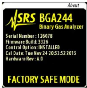
Firmware Update
A fatal error can be caused if a file is corrupted while being stored to flash during a firmware update. If this occurs, each time the unit is powered on it will enter the Factory Safe Mode.
Reinstall the Firmware to correct this error. Refer to Updating Firmware, page 143 for details. If this problem occurs repeatedly contact SRS for assistance.
Stored Setup
In rare cases, a corrupted stored setup can cause a fatal error. As part of the Factory Safe Mode, the Default setup will be loaded to enable this to be corrected. To determine if a corrupted stored setup caused the fatal error, reload it when the unit is in the Factory Safe Mode. If this causes a restart then that setup is corrupted.
The corrupted setup must to be deleted to correct this error. From the Factory Safe Mode, delete the setup and then restart the unit.
Firmware Error
In the unlikely event that the BGA244 gets a fatal error that isn't related to updating the code or a corrupted stored setup, the installed version of the firmware may contain a fatal error.
Confirm that this error is not caused by a stored setup before proceeding. Reinstall the firmware as described in Updating Firmware, page 143. Contact SRS for assistance if this problem occurs with the newly installed version.
Locked
The BGA244 keypad can be locked out with a password enable to keep unauthorized personnel from changing settings on the BGA244. This is indicated by the "Locked" message at the top left of the screen. Only the Home page can be viewed when the keypad is locked.
If you forget the password, the unit can be reset using the Hard Reset function described below. This will disable password locking and reset the password to the default value of 0000.
Store and Recall Failure
Setups are stored into Flash memory with a typical life time of about 100,000 erase cycles. In rare cases a large number of erase cycles can permanently “wear out” a particular memory location, rendering it unusable. Ordinarily a different memory location can be used. But if your application requires this particular location, the unit will have to be returned to SRS to replace and reprogram the Flash memory.
Note: Don't continuously store settings over the computer interfaces to avoid wearing out the memory. Practically this is the only way to wear out a location.
Touchscreen Problems
The LCD touchscreen can occasionally drift so that the displayed keys and keypress areas don't align. Running Screen Calibration (page 73) should fix this.
Use the following procedure in case the display has drifted so far that you cannot activate screen calibration.
■ Remove power to the unit.
- Press and hold a finger on the display while applying power. Keep it there until after the unit has fully booted and the About screen has vanished.
- At this point the screen will display "Release screen to start screen calibration". Remove your finger and follow the instruction to calibrate the screen.
Hardware Reset
The hardware reset button can be used to reset the BGA244. There are two different types of resets with slightly different behaviors. Use an unbent paper clip or a small screw driver to press the reset button. See Hardware Reset (page 91) for more details.
Normal Reset
Press the reset button once. Releasing the button forces a Normal Reset. This acts the same as power cycling the BGA244. This is ordinarily used if the BGA244 is in an unknown state and it is difficult to remove power to restart the unit.
Hard Reset
Press the reset button once. Release it, then immediately press and hold the button down for at least 10 seconds to execute a Hard Reset. This acts the same as power cycling the BGA244 and Recalling Setup 0 (Default Setup). Hard Reset is ordinarily used if the BGA244 is in an inoperable state where loading the Default Setup is impossible, or to reset a forgotten password.
Installing BGA-M
This section describes how to replace the standard cover (with LCD display) with accessory BGA-M, a rugged solid metal cover. This is typically done if the unit is operating in an environment where the LCD display may be damaged or broken.
Remember that units must either be configured prior to installation or over one of the computer interfaces since the LCD display and touch screen will be removed. The simplest way to configure the BGA244 over a computer interface is using the BGAMon software provided by SRS. See Chapter 5: BGAMon for more information. Otherwise it can be configured by user written code. See Chapter 6: Remote Programming for more information.
Replacement of the standard cover with BGA-M requires a Philips #1 screwdriver. Perform these steps with the unit on a flat surface clear of any obstructions.
Remove the eight 4-40 x ¼" black screws holding the top cover to the rest of the BGA244.
Lift the cover off of the BGA244. You may need to wiggle the cover a bit to remove it.
Place the BGA-M cover on the unit. Make sure the ground lug is on the same side as the terminal strip headers.
Loosely install the eight 4-40 x 1/4 " black screws holding the top cover to the rest of the BGA244. Tighten the screws.
Maintenance
The BGA244 does not require any regular maintenance or replacement of sensors, reference gases or filaments. The only user serviceable parts are the gas fittings (BGA244 only).
Replacing Gas Fittings
Ordinarily the NPT gas fittings of the BGA244 should never require service. However if they become damaged or worn due to improper or repeated threading they can be replaced. They can also be replaced by one of the accessory gas fittings or other male 1/8 "-27 NPT fittings for applications that require minimum insertion length. It is not recommended that NPT pipes be directly connected to the BGA244.
Removal and installation of the standard gas fittings requires a 9/16 th inch wrench. Disconnect any gas lines and electrical connections prior to removing a fitting. Perform these steps with the unit on a flat surface clear of any obstructions.
Removal Guidelines
- Grip the unit firmly across the top cover. Put the wrench on the desired gas fitting and turn the wrench counter-clockwise to initially loosen the fitting. Note that it may initially take a large amount of force to break the fitting loose.
- Continue unscrewing the fitting counter-clockwise until it comes out of the cylinder.
- Remove any loose thread sealant from the cylinder threads. Try to keep any contaminants or debris out of the BGA244 cylinder.
Use thread sealant when replacing the gas fittings. SRS recommends Loctite 565 thread sealant to seal leaks and prevent galling/seizing of the threads. A 0.2-oz tube of the Loctite is available from SRS (accessory 45855K12).
Installation Guidelines
- Apply a strip of thread sealant around the male pipe threads, leaving the first 2 turns uncovered.
- Finger tighten the adapter into the fitting.
- Grip the unit firmly across the top cover. Wrench tighten the adapter 2 ¼ turns past finger tight.
- Allow the Loctite 565 at least 24 hours to cure before applying pressure or vacuum to the system.
Replacing Gas Fittings for the BGA244E
As with the standard BGA244, the NPT gas fittings of the BGA244E should never require service. However if they become damaged or worn due to improper or repeated threading they can be replaced.
Removal and installation of the standard gas fittings requires a 9/16th inch wrench and either a pipe wrench or pliers. Disconnect any gas lines and electrical connections prior to removing a fitting. Be sure to have sufficient working space before attempting to replace the fitting.
Removal Guidelines
- Grip the tubing just below the enclosure seal of the BGA244E using a pipe wrench or pliers. Put the 9/16 th inch wrench on the gas fitting and turn it counter-clockwise to initially loosen the fitting. Note that it may initially take a large amount of force to break the fitting loose.
- Continue unscrewing the fitting counter-clockwise until it comes out of the tubing.
- Remove any loose thread sealant from the cylinder threads. Try to keep any contaminants or debris out of the BGA244E tubing.
Use thread sealant when replacing the gas fittings. SRS recommends Loctite 565 thread sealant to seal leaks and prevent galling/seizing of the threads. A 0.2-oz tube of the Loctite is available from SRS (accessory 45855K12).
Installation Guidelines
- Apply a strip of thread sealant around the male pipe threads, leaving the first 2 turns uncovered.
- Finger tighten the adapter into the fitting.
- Grip the tubing just below the enclosure seal of the BGA244 using a pipe wrench or pliers. Wrench tighten the adapter 2 ¼ turns past finger tight.
- Allow the Loctite 565 at least 24 hours to cure before applying pressure or vacuum to the system.
Terminal Strips
Replacement terminal blocks are available from Digikey or other distributors.
| Connector | Phoenix Contact p/n | Digikey p/n |
| C4, C6 (5 pin) | 1803604 | 277-1164-ND |
| C7 (8 pin) | 1803633 | 277-1167-ND |
| C8 (6 pin) | 1803617 | 277-1165-ND |
Cleaning
Clean the LCD display with either a spray glass cleaner or optical cloth.
Clean the casing with a mild detergent or spray cleaner. Take care to prevent any cleaner from entering the unit through the ventilation homes.
Calibration
The items that determine the BGA244's accuracy are the physical dimensions of the steel cavity, the crystal oscillator frequency and the temperature sensing thermistors. The physical dimension of the cavity doesn't change over time. The crystal oscillator and thermistors age at a rate several orders of magnitude lower than the BGA244's accuracy specification. Because of the lack of drift for any of the critical components in the BGA244 there is no specified periodic calibration interval.
The only item that suffers from any appreciable drift is the display. This can be calibrated using the Screen Calibration procedure (page 73) in Chapter 3.
The Performance Verification procedure described in the following section can be used to confirm that the BGA244 is operating properly and meeting its specification. Contact SRS for repair and calibration information if the unit fails any the following procedures.
Performance Verification
There are several parts to the performance verification procedure. Self Test confirms that the primary functions of the BGA244 are fully functional. The Analog I/O Tests verifies that the Analog Inputs and Outputs are operational and meet specification. The Measurement Accuracy Test confirms that the gas measurements meet the specified accuracy.
Self Test
Self Test checks the functional operation of many important internal components. It is automatically run upon power on. Self Test reports the status of the different tests on the Self Test page. It can also be started from the Self Test page (Home/Setup/Control Panel/Self Test). See Self Test (page 88) in Chapter 3 for details.
Self Test can also be initiated using the *TST? command. See *TST? (page 156) for a description of the command and definition of the return codes.
See Troubleshooting (page 197) for possible solutions to any Self Test failures.
Analog I/O Accuracy
These tests confirm that the BGA244s Analog Inputs and Outputs meet specification. Voltage and current outputs are tested using a DMM. Voltage and current inputs are tested comparing the BGA244 measurements with a DMM.
Required Equipment
■ Keysight 33461A 6½ digit DMM or equivalent. The key specification is 0.0035% DC Accuracy.
- 8 and 5 pin headers for the BGA244 terminal strips. See Terminal Strips (page 209) for replacements if needed.
■ Wires and leads to connect the BGA244 to the DMM.
Analog Measure Output
The Measurement Output value cannot be set directly. Instead the output is set by adjusting the Output Scale values and comparing the expected output to the measured output.
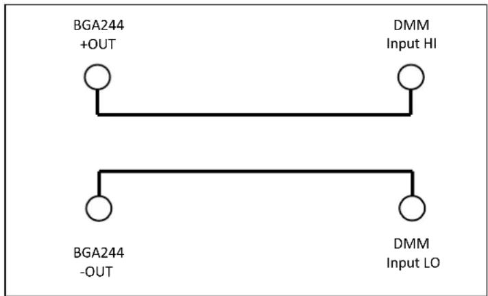
FIGURE 33: SETUP FOR MEASURE OUT VOLTAGE TEST

FIGURE 34: SETUP FOR MEASURE OUT CURRENT TEST
-
Connect the Measurement Output (C6) to the DMM as shown in Figure 33. Set the DMM to measure DC Volts at maximum resolution. Select auto range.
-
Recall the Default Setup. Go to (Home/Setup/Select Gas) and select whatever gas is currently in the gas chamber. This sets the BGA244 to measure the purity of the gas that is in the chamber. Confirm that the measurement is ±20% or less.
-
Go to (Home/Setup/Control Panel/Analog IO/Measurement Output). Set Scale Max to 100%. Verify that the BGA244 Output Value 1 and the DMM agree to within the limits listed in Table 28. Set Scale Max back to 10%.
-
Set Scale Min to -100%. Record the BGA244 Output Value 1 and the DMM measured value. Set Scale Min back to -10%. Verify that the BGA244 Output Value 1 and the DMM agree to within the limits listed in Table 28.
-
Change the Output Type to 0 - 5V. Repeat steps 3 and 4.
-
Connect the Measurement Output (C6) to the DMM as shown in Figure 34. Set the DMM measure DC Current at maximum resolution. Select auto range.
-
Repeat steps 3 and 4.
1 The BGA244 Output Value is displayed just below the Scale Max value.
TABLE 28: MEASURE OUT TEST LIMITS
| BGA244 Output Value | DMM Reading | Limits | |
| 0 – 10V Low | ± 1.22 mV | ||
| 0 – 10V High | ± 3.25 mV | ||
| 0 – 5V Low | ± 1.11 mV | ||
| 0 – 5V High | ± 1.12 mV | ||
| 4 – 20 mA Low | ± 15.45 μA | ||
| 4 – 20 mA High | ± 28.54 μA |
Analog Inputs and Outputs 1 & 2
The Analog Outputs can be set directly from the User setting. The outputs and inputs are connected together in loopback fashion and monitored using the DMM. Note that the Analog In limits are calculated relative to the DMM measurement, not the Analog Output values.
![graph TD A["BGA244 +OUT"] --> B["○"] C["BGA244 +IN"] --> D["○"] E["DMM Input HI"] --> F["○"] G["BGA244 -OUT"] --> H["○"] I["BGA244 -IN"] --> J["○"] K["DMM Input LO"] --> L["○"]](/content/2026/06/1372977/images/1b6dfb4a5973e3b81485ece2a8dc8cd048afd795f8ef941fa3be831558a9e9b3.jpg)
FIGURE 35: SETUP FOR ANALOG I/O VOLTAGE TEST

FIGURE 36: SETUP FOR ANALOG I/O CURRENT TEST
- Connect Analog Output 1, Analog Input 1 (C7) and the DMM HI input as shown in Figure 35. Set the DMM to measure DC Volts at maximum resolution. Select auto range.
- Recall the Default Setup. Go to (Home/Setup/Control Panel/Analog IO).
- Set Analog Output 1 User Setting to 1 V. Verify that the DMM, BGA244 Output and Input values all agree to within the limits listed in Table 29.
- Set Analog Output 1 User Setting to 10 V. Verify that the DMM, BGA244 Output and Input values all agree to within the limits listed in Table 29.
- Change the Output Type to 0 - 5V. Repeat steps 4 and 5 for 0.5V and 5V.
- Connect Analog Output 1, Analog Input 1 and the DMM I input as shown in Figure 36. Set the DMM to measure DC Current at maximum resolution. Select auto range.
- Change the Output 1 Type to 4 - 20mA.
-
Set Analog Output 1 User Setting to 4 mA. Verify that the DMM, BGA244 Output and Input values all agree to within the limits listed in Table 29.
-
Set Analog Output 1 User Setting to 20 mA. Verify that the DMM, BGA244 Output and Input values all agree to within the limits listed in Table 29.
-
Repeat steps 1 to 10 for Analog Output 2 and Analog Input 2 (C7).
TABLE 29: ANALOG I/O TEST LIMITS
| Set Value | DMM | V Out Limit | Analog In | V In Limit 1 | |
| 0 – 10V | 1 V | ± 1.25 mV | ± 1.25 mV | ||
| 0 – 10V | 10.0 V | ± 3.50 mV | ± 3.50 mV | ||
| 0 – 5V | 0.5 V | ± 1.12 mV | ± 1.12 mV | ||
| 0 – 5V | 5.0 V | ± 2.25 mV | ± 2.25 mV | ||
| 4 – 20 mA | 4 mA | 14.0 μA | 14.0 μA | ||
| 4 – 20 mA | 20 mA | 30.0 μA | 30.0 μA |
1 Note that the Analog In limits are calculated relative to the DMM measurement, not the Analog Output values.
Measurement Accuracy
This test confirms that the BGA244 meets its accuracy specification for gas measurements. This is done by flowing pure Argon through the cell and confirming that the measured speed of sound is within tolerance of the ideal speed of sound.
The exact configuration of the gas systems can vary and may be incorporated within the user's installation. The most important requirements are to:
■ Ensure that pure Argon is flowing through the BGA244
■ Enter the correct analysis pressure
Required Equipment
Tank of at least 99.99% pure Argon
The BGA244 should vent to atmosphere with minimal pressure drop. A short length of tubing or other apparatus can be connected from the BGA244 outlet to atmosphere if necessary. Be certain that the pressure drop from the BGA244 outlet to atmosphere is <1 psi (6.9 kPa).
- Power on the BGA244. Recall the Default Instrument setup. (Home/Setup/Store|Recall/Recall/Default)
- Go to (Home/Setup/Pressure/Enter_User_Pressure/Ambient). Enter the atmospheric pressure of your location as the Ambient pressure value. Ordinarily this value will depend primarily on your elevation. Use the closest value from the Table 30.
TABLE 30: PRESSURE VS ALTITUDE
| Elevation | Nominal Atmospheric Pressure |
| Sea level (0' or m) | 14.7 psi (101 kPa) |
| 1000' (305 m) | 14.2 psi (98 kPa) |
| 2000' (610 m) | 13.8 psi (95 kPa) |
| 3000' (914 m) | 13.2 psi (91 kPa) |
| 4000' (1219 m) | 12.8 psi (88 kPa) |
| 5000' (1524 m) | 12.3 psi (85 kPa) |
| 6000' (1829 m) | 11.9 psi (82 kPa) |
| 7000' (2134 m) | 11.5 psi (79 kPa) |
| 8000' (2438 m) | 11.2 psi (77 kPa) |
| 9000' (2743 m) | 10.7 psi (74 kPa) |
| 10,000' (3048 m) | 10.3 psi (71 kPa) |
- Flow at least 2 liters of Argon at 200 - 1000 sccm to fully purge the BGA244.
- Check that the Gas Purity measurement has fully settled. If not, wait until it settled.
- Confirm that the Gas Purity measurement is ≤±0.05% .
Chapter 8: Circuit Description
Overview
The BGA244 determines the ratio of two known gases by measuring the speed of sound and temperature of the gas and calculating the concentration required for those values.
The speed of sound is measured by injecting an acoustic signal into a resonant gas chamber with a wide bandwidth transducer. The resonant modes of the cell are excited, producing large amplitudes at the resonant frequencies. This signal is measured by another wide bandwidth transducer. Digital signal processing is used to precisely measure the resonant peaks and from them, the speed of sound.
The temperature is measured using two separate bead thermistors in bridge configuration. The thermistors are measured by 24 bit ADCs.
Besides the core measurement functions the BGA244 has a touchscreen LCD display with a graphical user interface to set and display measurements plus three separate computer interfaces, multiple analog inputs and outputs, and event based relay contacts. The BGA244 can be powered over USB or +24 VDC .
Block Diagram
(Schematic 1: Block Diagram)
The Analog Devices ADSP-BF522 embedded processor manages all aspects of the BGA244's operation. It controls the LCD display, computer interfaces, analog I/O in addition to performing the digital signal processing to determine the speed of sound. Besides 132 kbytes of internal memory, the processor interfaces to an external 256 Mbit DRAM. The processor code, graphics and gas data are stored in a 256 Mbit Flash ROM.
The ADSP-BF522 has internal UARTS to control the RS-232 and RS-422 interfaces and connects to the USB interface chip.
Signal Processing Algorithm
The ADSP-BF522 processor outputs a minimum crest factor, FFT chirp waveform to the CODEC DAC. This signal is amplified and then sent to the speaker transducer inside the acoustic resonant cell. The microphone transducer on the opposite end of the resonant cell receives the acoustic signal which is primarily made up of the resonant frequencies of the cell. This signal is amplified about 1000 times by an extremely low noise preamplifier. It's then filtered, sampled by the CODEC ADC and finally input to the processor.
The processor performs a Fast Fourier Transform on the input data to calculate the frequency spectrum of the acoustic signal (again primarily made up of the resonant modes of the cell). A multiplicative correlation technique is used to compare the measured spectrum with a reference spectrum to identify the approximate peaks of the resonant modes. Finally a Lorentzian function is fit to the points around the primary resonant peak to precisely determine its center frequency.
The center frequency of this mode combined with the precise dimensions of the cell determines the speed of sound of the gas within the cell. This speed is slightly modified by the temperature, the physical properties of the gas and plus some calibration constants to determine the speed of sound of the gas in free space. This value is used to determine the measured values of purity, concentration or NPT speed of sound of the gas.
Detailed Circuit Description
There are several sub-assemblies for the BGA244 electronics.
- Main Board (Schematics 2-6)
- Speaker Board (Schematics 7-8)
- Microphone Board (Schematics 9-10)
- Industrial Board (Schematic 11)
- Control Board (Schematics 12-15)
Main Circuit Board
The Main board contains the ADSP-BF522 processor, memory, CODEC, local power supplies, and interfaces to the LCD and other circuit boards. It is mounted across the top of the other circuit boards and the resonant gas chamber. There are five pages of schematics for this board.
Schematic 2: DSP & bypass
U101 contains 2/3 of the ADI ADSP-BF522 embedded processor. It controls all of the instrument functions, including signal processing, user interface & computer interfaces. It is a 16 bit fixed point processor with dual MACs and a wide range of embedded peripherals. These include I2S ports, SPI ports, UARTs, data bus, address bus and SDRAM controller. Because all of the outputs of the BF522 have fast edge rates, 33 ohm source termination resistor are provided for signal integrity. Upon power up, all of the BF522 I/O pins are configured as inputs. Signals that may be sensitive to floating values are pulled to either 3.3V or gnd.
The BF522 operates on three power supply voltages: 3.3V for external signals, 1.4V for the core and 2.5V for the BF522 boot sequence ROM. (U102)
The I2S ports (Rx0, Tx0 DAT, CLK, FS) connect to the CODEC (Schematic 3) for inputting and outputting acoustic signals. The SPI ports (MISO, MOSI, CLK & numerous CS lines) control most of the devices on the BGA244. These include the Flash ROM, touch screen controller, USB interface, DACs, ADCs and other control lines.
The data bus connects to the SDRAM (Schematic 2) and the LCD (Schematic 4). The address bus, along with the SDRAM controller lines connect to the SDRAM (Schematic 2). The only address or control lines that connects to the LCD are -AMS1, -RD, -WR and -OE.
There are 5 active timer outputs to control various devices. Timer 0 drives the beeper (Schematic 4). Timer 1 provides the ADC Sync to synchronize the 24 bit ADCs to the processor clock (Microphone, Speaker and Control boards). Timer 5 drives the LCD back light to adjust brightness (Schematic 4). Timer 6 provides the SWPS sync to synchronize
the +24 to +5V switching power supply to the processor clock (Industrial board). Timer 7 synchronizes the DSP switching power supplies to the processor clock (Schematic 5).
There are 14 general IO lines that are used to control or monitor several different signals. These include two IRQ lines (Touch Screen & DAC), the LCD register, heater enables and USB status lines.
TP101, 105, 106, 107, 108, 109 are test points for the SDRAM signals (bottom side of PCB). TP102 (top) is the LED CS, TP103 (bottom) is the AUX_ADC CS and TP104 (top) is the USB SPI CS. TP110 is a test point for the +2.5V supply.
Schematic 3: Memory, Communications and Reset
This page contains the system memory, USB & RS-232 interfaces and the remaining 1/3 of U101B (BF522) containing the UARTS, I2C interface, reset, boot logic and emulator port.
U201 (MT48LC16M16A2) is a 4M x 16 bits x 4 banks SDRAM where most of the processor code runs. It interfaces to the BF522 over the data bus, address bus and the SDRAM controller lines. Note that the address bus starts at A1 (not A0) since all addressing is 16 bit words (A0 would be used for byte addressing). SA10 must be connected to A10 for auto-refresh to operate. A18, A19 are connected to bank select BA0, BA1, regardless of memory size.
U202 (S25FL256S) is the 256 Mbit serial flash EEPROM where all code and data is stored. The BF522 has no internal non-volatile memory, so all configuration data is also stored here. During normal operation the BF522 begins loading from U202 immediately after power on. The first part of the data contains instructions to increase the reading speed to the fastest rate possible (20 MHz). Even so, it takes \~10 seconds to load all of the code and data.
U203 (FX220X) is an SPI to USB interface device that supports UART like ASCII text commands. It has a non-standard SPI interface with data read and write on the same pin. This is isolated from the SPI bus by U208A and R221. During write portion of the operation the SPI writes MOSI as usual and ignores the MISO read data. For the read portion the MOSI is left in a static state and the data is read on MISO. On power up, U203 requires the MIOSI lines pulled high to properly configure the serial interface. Control lines USB_CS, USB_DI and CBUS are pulled high and USB_SCLK is pulled low. Non SPI status information is passed to the BF522 over USB_DI and USB_STAT. VCCIO regulates the +5V to +3.3V for use within U203. Reset is powered by USB+5V, ensuring that U203 is reset whenever a USB device isn't attached. TP201/202 are test points for USB_DI & USB_STAT (bottom).
U204 (TPD2S017), a 2-channel, low voltage ESD clamp with a 1 Ω series resistor isolates the USB data lines from the USB-B connector (J201). It and C204/205 act to limit any ESD events to a non-destructive level. The USB +5 passes thru CM choke T201 and LC filter L201/C206 to provide system power over USB when it is active. RV201 clamps the USB_+5 to below +7V to avoid damaging other components.
U101B, UART0 connects to line driver/receiver U206 (ADM3202) and DB9 connector J202 for the RS-232 interface. Status lines CD & DSR are pulled up to +6.5V from U206 (TP206). UART1 is routed to the Industrial board for the RS422 interface.
Tx, Rx, CTS & RTS are described relative to the destination pin names (i.e. at a PC serial port) and are designed to work with a straight thru cable (no pin 2-3 swap). So the remote devices Tx goes to the BGAs UART Rx and the remote device CTS goes to the BGAs RTS.
The I2C interface (U101 SDA, SCL) controls two devices: the CODEC (U302) and boot mode setting (U207). SDA and SCL can be accessed by top side test points TP204 (SDA) and TP205 (SCL). I2C is set to operate at 3.3V (BUSTWI = 3.3V).
J203 is the JTAG debug port used to connect to the emulator. The processor clock (18.432 MHz) comes from U302 (Schematic 3).
The BF522 boot mode is controlled by non-volatile trim DAC U207 (DS3904) and R222-R226. Prior to being programmed, U207 resistors default to their maximum value of 20 kΩ. Combined with pull up & down resistors, this sets the Boot Mode to 0111 (Mode 3|2|1|0) which selects UART0 (RS-232) as the initial boot device. After the code has been downloaded for the first time, the BF522 sets U207-R2 to 0 Ω changing the Boot Mode to 0011, or SPI memory boot for normal operation. If necessary JP201 can be inserted to force the Boot Mode back to UART0 (RS-232).
U205 (ADM13305) is a processor supervisor and reset controller. It senses both the +1.4 V core and the +3.3 V IO voltages and holds the processor in reset until they are stable. The processor also can reset U203 by toggling PROC_RST. The reset out line is buffered by U209A (74LV3G34) to U202 and the LCD display (Schematic 4).
Schematic 4: CODEC, Aux ADC and Reference
U302 (SSM2603) is a two channel CODEC (ADC/DAC) used to input and output the acoustic signals to/from the acoustic transducers. Only one input and one output channel are used. U302 is clocked by Y301, an 18.432 MHz, AT cut, fundamental mode crystal. This clock is output from U302 and buffered by U304 (74LVC1G04) to the BF522 as the system clock (TP303). U302 transmits/receives data with the BF522 over I2S (TX/RX0 DAT, CLK & FS). It operates in master mode, providing all clocking to pass data to/from the BF522.
The SSM2603 operates at a 72 kHz FS. Test points TP304, 307, 308 & 309 (bottom) and R101 (top) allow the serial lines to be probed. (Use R101 for TXDAT). U301 (LP2985) provides a low noise +3.3V power supply.
U302 is configured as indicated over the I2C interface (addr 0011011 binary). See the SSM2603 data sheet for details. Besides the initial settings, the BF522 may adjust the ADC gain dynamically to optimize SNR.
Master Mode, I2S, 24 bit word, non USB, High pass Active
CLK DIVs = 0, BOSR = 1, SR3:0 = 1000 (BCLK = MCLK/4, SR = MCLK/256)
The SSM2603 is an oversampling converter with digital filters for the DAC and ADC. The DAC and ADC filters attenuate images/aliases from 40kHz (0.555 FS) to 18.432MHz by 61 dB. External analog filters must attenuate images/aliases above 18.432MHz .
R301/C309 & C308/310 & the CODEC input resistance form low pass (138 kHz) and high pass (between 1.7 Hz - 80 Hz depending on the input gain) filters for the Left ADC input. This combined with the input gain filters on the Microphone board (Schematic 8) attenuate out of band signals as shown in the table.
| Freq | Total Attenuation |
| 120 Hz | -68 dB |
| 1 kHz | -1.0 dB |
| 32 kHz | -1.2 dB |
| 18MHz | -119 dB |
The DAC output filter is made up of U303 (AD8601) and associated R's & C's, which form an AC coupled 2nd order 138 kHz low pass, Butterworth filter. This signal is offset to 2.048 Vdc by R310-311. The response combined with the output AC coupling on the Speaker board (Schematic 9) gives the following response.
| Freq | Total Attenuation |
| 1 kHz | -0.3 dB |
| 32 kHz | -0.06 dB |
| 18 MHz | -88 dB |
U307 (ADR4540) is the 4.096 V system voltage reference used throughout the BGA244 (TP306). The part is capable of sourcing 10 mA, but will draw a maximum of <5 mA.
U306 is the Auxiliary ADC (ADC880S022). It is an 8 channel, 8 bit ADC used to monitor several power supplies and the magnetic field sensors. This circuit will operate even if the +5V System voltage drops below the specified range (4.75V – 5.25V). This allows the BGA to correctly measure the +5V supply to as low as 3.5V. It uses a 3.3V reference, buffered by U305 (AD8601) to minimize noise (TP305). The signals measured, scale factors and the expected values (at the ADC) are listed below. Full scale for the ADC is +3.3V.
TABLE 31: AUXILIARY ADC VOLTAGES
| Input | Signal | Scale | Expected | Comments |
| 0 | Mic Membrane | 0.5 | 1.0 – 2.0 | Fault if outside the range |
| 0 | Mic Mag Sense | 0.5 | 0.5 – 1.5 | 2.5 mV/gauss centered on 1.024V |
| 1 | Spkr Membrane | 0.5 | 1.0 – 2.0 | Fault if outside the range |
| 1 | Spk Mag Sense | 0.5 | 0.5 – 1.5 | 2.5 mV/gauss centered on 1.024V |
| 2 | +3.3V good | 0.8 | 2.4 – 2.9 V | Lo when not +/- 10% of nom |
| 3 | +1.4V good | 1.0 | 1.3 – 1.5 V | Lo when not +/- 10% of nom |
| 4 | V USB | 0.5 | 2.4 – 2.6 | V USB/2 |
| 5 | +24 V | 0.10 | 1.8 – 2.6 | +24/9.87 |
| 6 | +4.5V | 0.667 | 2.9 – 3.1 | 2/3 * 4.5V |
| 7 | +5 Industrial | 0.5 | 2.4 – 2.6 | +5_Ind / 2 |
Schematic 5: User Interface and End Board Connectors
This contains all of the user interface functions (LCD w/ touch screen, LEDs, beeper, reset button) as well as the connectors for the speaker, microphone, industrial and control boards.
J405 is the connector for H401, the LCD display with touch screen (HY32D). It interfaces to the BF522 over the data bus at a single address set by -LCD_CS. REG_SEL selects if data is sent to the display buffer or control registers. The LCD controller chip (initially SSD1289, but could be HX8347A or ILI9320 in the future) contains an onboard frame buffer, so only changes need to be written to the display. This minimizes the communication between the BF522 and the LCD.
The touch screen controller chip interfaces to the BF522 over the SPI bus and a single interrupt line. The LCD back light can be dimmed by toggling the back light control (BL_CTL).
The Power LED (D401) turns on when power is applied since the BF522 IO lines default to inputs and the line is pulled down by R402. The BF522 can control this LED to display blink codes to indicate power problems with the BGA244 without the display being active or even present.
The remaining LEDs (D402-403) are controlled from the SPI bus using shift register U401 (74LV595). The LED drive signals are active low. R403-8 set the brightness of the LEDs. Note that LEDs D404, D405 & D406 are not populated. Besides the LEDs there are 3 additional control signals: -MAG_ENA (magnetic sensor enable), MIC_BHEAT and SPK_BHEAT (Mic & Speaker Block Heater Enable). -MAG_ENA enables the magnetic field sensors on the Speaker & Microphone end boards to prior to them being measured (by ADC U306). After measurement they are disabled. MIC_BHEAT_ENA and SPK_BHEAT_ENA (active hi) enable the block heaters on the Mic and Speaker end boards.
| Bit | Function | LOCATION |
| 0 | -COMM LED | D402 |
| 1 | -ERROR LED | D403 |
| 2 | Not used (future expansion) | D404 |
| 3 | Not used (future expansion) | D405 |
| 4 | Not used (future expansion) | D406 |
| 5 | -MAG_ENA | J402-3 & Schematic 7 & 9 |
| 6 | MIC_BHEAT_ENA | J403, Schematic 7 |
| 7 | SPEAKER_BHEAT_ENA | J402, Schematic 9 |
U402 A&B and associated components form a 3rd order low pass filter and bridge amp to drive piezo speaker SPK401 (CMT-1603). The bridge is used to increase the available drive signal and balance the drive current. It will be controlled through Counter 0 of the BF522 (Schematic 1) by a pulse train with a 4 kHz dominant frequency. The speaker is used for key clicks, alarms and other sounds.
SW401 is the recessed reset button used to reset the BGA244. This is important for the non-display version (BGA-M accessory) or as a total reset function.
J401-J404 are connectors for the Speaker, Microphone, Industrial and Control boards. They carry power, digital and analog signals between the various boards. These boards contain the following functions:
■ Speaker Board (J402): Heater configuration & control, gas temperature measurement, magnetic field measurement and speaker driver circuitry.
- Microphone Board (J403): Heater configuration & control, gas temperature measurement, magnetic field measurement and microphone pre-amp and filtering circuitry.
- Industrial Board (J401): 24 V input connectors, 24 → 5 V power supply, Measure Analog Output, RS-422.
■ Control Board (J404): 2x Analog Outputs, 2x Analog Inputs, Loop Power Voltage, Event Relays.
Schematic 6: Power Supplies
U501 (LTC4413-1) is a "Dual Ideal Diode" power supply selector used to select either USB +5V or Industrial +5V (from the Industrial board) for the System +5V. If IND +5V is present ENABLE_A is pulled high, disabling V_USB. If the IND +5 is absent ENABLE_A is low, allowing current to be drawn from V_USB.
U502 (LP3982) is a low dropout adjustable regulator set to 4.5V. U502 has an extremely low dropout voltage (<200 mV) so the minimum V_USB of +4.75 will be sufficient to provide power. 4.5A_Fault will go low if the regulator current limits, goes into thermal shutdown or drops out of regulation. This is monitored by the BF522 (U101, Schematic 1).
U503 and U504 (AD2120) are step down DC-DC switching regulators that convert the +5V System to +3.3V and +1.4V for the BF522 and other digital logic. On startup, before the BF522 is active they operate at \~1.2 MHz until the DSP_PWR_SYNC becomes active and synchronizes them to the system clock (1.2009 MHz). +3.3V_GOOD and +1.4V_GOOD go high (+3.3, 1.4 V) when their outputs are +/-10% of the expected values. These signals are monitored by Auxiliary ADC U306.
The following Test Points are available to measure the power supply voltages.
TABLE 32: POWER SUPPLY TEST POINTS
| Location | Name | Expected |
| TP110 | +2.5 V | 2.4 – 2.6 |
| TP501 | V_USB | 4.75 – 5.25 V |
| TP502 | +5_SYS | 4.7 – 5.2 V |
| TP503 | VCC_STAT | 4.7 – 5.2 V |
| TP504 | +4.5A | 4.3 – 4.7 V |
| TP505 | +3.3V | 3.2 – 3.4 V |
| TP506 | +1.4 | 1.3 – 1.5 V |
Microphone Board
The microphone board contains circuitry that interfaces to the microphone end of the acoustic cell.
Schematic 7: Temperature Sense & Heaters
This page contains the heater and thermometry for the Microphone Board. Note that the heater circuitry is only active when +24V is present.
Heater
The heater circuit is made up of three separate control loops:
- The temperature loop which adjusts the heater power loop until the endplate temperature matches the set temperature.
- The current limit loop that reduces the output of the temperature control loop when the current exceeds the limit value.
- The heater power loop that adjusts the power dissipated in the heating elements to match the requested power setting from the temperature control loop.
The temperature control loop is implemented as a PI control loop. The temperature set point comes from DAC U603A (MAX5222, set over SPI). The temperature is sensed by thermistors (RT601, RT602) mounted to the end plates and buffered by U604 (AD8601). This signal MIC_HEAT_SEN is monitored by ADC U607 (LTC2492). The response of the control loop is set by C602/C603 and R613. P_SET (the heater loop input) is determined by the lower of the temperature servo value and the current limit value.
U601 and Q601 are the power elements for the heater control loop. They are both mounted directly to the end plate. U601 drops the +24 V to +12 V. The current through Q601 is servoed by comparing the voltage drop across R601 to that of I_SET. The power delivered to U601 and Q601 is P = (12V * I amps) each. The maximum power delivered to each end plate is 26 watts (1.1 A). C601/R608 set the loop time constant to \~95 ms. D601 ensures that U601's output isn't stuck low during power on.
The temperature loop output (PSET) value is based on how close the actual temperature is to the set temperature. The actual temperature (MIC_HEAT_SEN) is sensed by thermistors RT601 & RT602. It can vary from about 0.6 to 3 V. A table of the approximate voltage vs temperature values is shown below (more accurate calculation are made in the firmware using the Steinhart-Hart equation). The set temperature (T_SET) is set by DAC U803A between 0 – 4.1 V DC . When the current limit is not active, the T sense and T set values are compared by U602 to determine the required heater power.
| Temp (°C) | Voltage ( VDC) |
| 0 | 3.138 |
| 10 | 2.728 |
| 25 | 2.048 |
| 35 | 1.622 |
| 50 | 1.085 |
| 60 | 0.815 |
| 70 | 0.610 |
The heater power being requested by the temperature servo circuit is determined by the following formula (this assumes that the current limit is not active).
Power Requested = V _ 2 4 * (PSET - 0. 2 2) * 0. 1 0 4
So if PSET is <0.22 V, no power is being requested by the servo. If PSET = 9.79 V, 24 watts is being requested (assuming V24 24 V). This relationship is shown in the following table.
| Heater Current | P_SET (voltage) |
| 0 | 0.22 |
| 0.2 | 2.13 |
| 0.5 | 5.01 |
| 1.0 | 9.79 |
| 1.2 | 11.7 |
The current limit loop is programmed by I_LIM, which determines the maximum current that can be delivered to the heater. It is set by DAC U603B (MAX5222). U605B (LMC6482) takes over control of the temperature control loop when the current limit is active. P_SET is monitored by ADC U607 (LTC2492).
The current limit limits the maximum value of PSet. If PSet/3 exceeds the DAC voltage, U605 will increase the apparent set temperature (by pulling the voltage down thru D602) until the current equals the current limit value. It is set per the formula:
I _ Lim = 0. 0 7 3 + 3. 1 9 I _ Out
For active current limit the maximum values of PSet are listed in the following table.
| Heater Current | P_SET (voltage) | I_LIM (voltage) |
| 0 | 0.22 | ~0.07 |
| 0.2 | 2.13 | 0.71 |
| 0.5 | 5.01 | 1.67 |
| 1.0 | 9.79 | 3.26 |
| 1.2 | 11.7 | 3.90 |
If the block heaters are inactive, the heater control loop is programmed to an idle voltage using switch U609 and amplifier U605 & associated components. This is avoid having the heater servo amp saturate when the heater is disabled. The heater is enabled by MIC_BHEAT_ENA.
Temperature Sense
The 100 kΩ gas temperature sensing thermistor inside the cavity (connected to J602, J603) connects between VREF and ground thru R619 and R620. The nominal power dissipated in the thermistor at 25 °C is about 0.38 μW. The voltage across the thermistor is:
Vout = Vref (Rt/Rt + 2 MΩ)
A table of Vout/Vref vs temperature is shown below. A more accurate voltage vs temperature calculation is made in the firmware using the Steinhart-Hart equation.
| Temp (°C) | Resistance (kΩ) | Vout/Vref |
| 0 | 326.54 | 0.14035 |
| 10 | 199.03 | 0.09051 |
| 25 | 100.0 | 0.04762 |
| 35 | 65.30 | 0.03162 |
| 50 | 36.03 | 0.01770 |
| 60 | 24.88 | 0.01229 |
| 70 | 17.52 | 0.00868 |
This signal is measured by ADC U607 (LTC2492). This is a 24 bit ADC with digital filtering for 50/60 Hz, with additional filtering provided by the bridge resistors and C611 (289 Hz). This combined with the ADC internal response provides -46 dB of alias protection at 14 kHz. The ADC is controlled over the SPI bus.
The converter also measures MIC_HEAT_SEN and P_SET as single ended signals as well as and its own internal temperature. The ADC is synchronized to the system clock by MIC_SYNC (281.06 kHz) and uses the 4.096 V reference.
The BGA244 makes 8k FFTs of the acoustic spectrum which takes about 227.56 ms to acquire. ADC measurements are made synchronously with this. During each FFT period the gas temperature is measured (\~146 ms at 1x rate) followed by measurements of either MIC_HEAT_SEN or P_SET (\~73ms at 2x rate).
Schematic 8: Preamp and Transducer Sensors
This page contains the low noise preamp and magnetic and membrane sensors that monitor the transducer.
Preamp
The microphone transducer membrane connects between J701 and ground inside of the cavity. This signal is AC coupled by C703/704, then amplified by Q701. U701A (AD8602) provides an active collector load of 5 mA and holds the collector voltage at 1.0 V. U701B biases Q701's base so the output of U701A is at an average of 4.096 VJC . The AC portion of Q701s collector current is amplified by the 619 Ω resistor across U701 to give a gain of 100. The gain is a function of the transistor Q701 and is not a precise value.
This signal is amplified 20 dB by a 4th order high pass Butterworth filter (at 300 Hz) to remove line frequency signals. There is some additional low pass filtering to limit the high frequency bandwidth. Gain is added to the usual Butterworth topology by increasing the non-inverting gain, then dividing the feedback voltage so the circuit sees the original feedback signal. (R708/709, R713/714). This signal connects with the main board and is digitized by the CODEC (Schematic 3).
To minimize cross talk from the speaker to microphone, it is necessary to isolate the signal ground. AGNDM is a local ground for the preamp section that connects directly to end plate ground directly at the transducer (J702). R723 allow the circuit to operate without the block being present.
The gain of the entire preamplifier is 60 dB, with high and low pass roll offs as listed. The noise figure is 2.9dB over the 45Ω membrane resistance noise; total input referred noise is 1.2nV / VHz (including 45Ω membrane).
| Freq | Attenuation |
| 60 Hz | -91 dB |
| 844 Hz | -3 dB |
| 1 kHz | -1.0 dB |
| 32 kHz | -1.0 dB |
| 61.7 kHz | -3.0 dB |
| 18 MHz | -77 dB |
Transducer Sensors
U706/U707 (MAX4624) are controlled by MIC_MHEAT to enable the membrane heaters. The heater current is limited by R725, the membrane resistance and the ON resistance of U706/U707 (1 Ω each) to around 65 mA. The switches are in a "T" configuration to minimize any noise pickup from the power supply. The membrane heater is only used during degas or self test with no acoustic signal present.
U705 (A1393) is magnetic field sensor that provides an analog voltage proportional to the magnetic field it is exposed to. The sensor voltage is measured by the Aux ADC (Schematic 3). It takes 120 µs for the sensor to settle after being enabled by MIC_MAG. Normally the sensor will only be read during self-test. The output voltage varies by 5mV / gauss centered on 2.048V(= 0gauss) .
| -MIC_MAG = 0 | Enabled |
| -MIC_MAG = 1 | Disabled |
U708 (MAX4624) selects the analog voltage from either the membrane heater or the magnetic field sensor. It is controlled by MIC_MHEAT (0=Mag Sense, 1=Mem Heat).
Speaker Board
The Speaker Board contains circuitry that interfaces to the speaker end of the acoustic cell.
Schematic 9: Temperature Sense & Heaters
This page contains the heater and thermometry for the Speaker Board. Note that the heater circuitry is only active when +24V is present.
The circuitry on Schematic 8 is essentially the same as Schematic 6. See Schematic 6 for details on operation.
Schematic 10: Output Amplifier and Transducer Sensors
This page contains the output amplifier and magnetic and membrane sensors that monitor the transducer.
Output Amplifier
The output signal from the CODEC (Schematic 3) is AC coupled to establish a local bias voltage. It is buffered by U901 (AD8601) and AC coupled thru C902/C903 to the membrane which is connected between J901 and ground inside of the cavity.
To minimize crosstalk from the speaker to microphone, it is necessary to isolate the circulating current from the power amplifier thru the transducer membrane to ground from the rest of the circuitry.
The largest crosstalk problem comes from the amplifier current (used to drive the 45 Ω membrane) coming from the system power supply. To remove the AC component of this, U901 is powered by a current source, forcing all of the AC current (above 8 Hz) to come from C907/908/909, instead of the system power regulator (TP902).
The second technique to reduce crosstalk is to isolate the signal ground. AGNDs is a local ground that connects directly to end plate ground directly at the transducer (J902). R912 allows the circuit to operate without the block being present.
Transducer Sensors
Q902 (2N3906) is controlled by SPK_MHEAT to enable the membrane heaters. The heater current is limited by R911, the membrane resistance and the saturation voltage of Q902 (\~0.2V) to around 65 mA. The membrane heater is only used degas or self test with no acoustic signal present.
U903 (A1393) is magnetic field sensor that provides an analog voltage proportional to the magnetic field it is exposed to. It takes 120 µs for the sensor to settle after being enabled. The sensor voltage is measured by the Aux ADC (Schematic 3). Normally the sensor will only be read during self-test. The sensor is enabled by -SPK_MAG. The output voltage varies by 5mV / gauss centered on 2.048V(= 0gauss) . See the A139x data sheet for details.
| -SPK_MAG = 0 | Enabled |
| -SPK_MAG = 1 | Disabled |
U907 (MAX4624) selects the analog voltage from either the membrane heater or the magnetic field sensor. It is controlled by SPK_MHEAT (0=Mag Sense, 1=Mem Heat).
Industrial Board
The industrial board contains the 24VDC to 5VDC converter, RS-422 interface drivers and Measurement Output DAC.
Schematic Page 11
+24 VDC can be applied to the interface option thru either J101 (2.1mm coax jack) or pins 5 & 4 of J102. +24 VDC is protected from reverse polarity and isolated by D101 (MBRD660). D107, D108, D109, D110, D111 protect from transients. +24 VDC and ground are common mode filtered by T101. System +24 V is further filtered by L101/C101 to remove any high frequency content (>5 kHz).
U101 (LM22672-ADJ) is a DC-DC switching regulator used to convert the +24 VDC to the system +5 VDC . It is held in reset until the input voltage exceeds 18 VDC . When first powered on, U101 will operate at \~500 kHz until the BF522 starts PS_SYNC which synchronizes it to 771.018 kHz.
U103 (AD5422) is a 16 bit V/I output DAC for the Measurement analog output from the BGA244. The DAC can output voltage or current (0 to +5 V, 0 to +10 V or 4 to 20 mA). It is set and monitored over the SPI bus and uses shared interrupt line DAC_INT to inform the processor of overloads.
For voltage output U104 (OP113) senses the output voltage after protection resistor R106 and RT101. Q101 is a pass element for current output to minimize temperature shift inside U103. R108 is a precision current sense resistor to improve current output accuracy.
C116/7 and L103 act as a filter to remove input/output noise. The Measure Output and return connect to J102 pins 3 and 2. D104 and D105 protects against reverse polarity. R106, RT101 & D103 protect V out from ESD transients, while R107 protects U104.
U107 (LTC2863) is a line driver-receiver that converts the UART1 Tx and Rx signals from the BF522 to RS-422 levels. D108 protects U107 from ESD transients. The RS-422 signals connect to J104 pins 5 to 2.
Control Board
The Control board contains Analog Outputs 1 & 2, Analog Inputs 1 & 2 and the Event Relays.
Schematic Page 12: Analog Outputs 1 & 2
U101 & U103 (AD5422) is a 16 bit V/I out DACs used to output Analog 1 & 2 signals from the BGA244. They can independently be set to output voltage or current (0 to +5 V, 0 to +10 V or 4 to 20 mA). They are set and read over the SPI bus and use shared interrupt line -DAC_INT to inform the processor of overloads.
For voltage output, U102/104 (OP113) senses the output voltage after protection resistors R101/105 and thermistors RT101/102. Q101 & Q102 are pass elements for current output to minimize temperature shift inside U101/103. R104/108 are precision current sense resistors to improve current output accuracy.
C101/102, C111/112 and L101/102 act as filters to remove input/output noise. D102/103 and D105/106 protect against reverse polarity. R101/105, RT101/102 & D101/104 protect V out from ESD transients, while R103/107 protects U102/4.
Schematic Page 13: Analog Input 1
U206 (LTC2492) is a 24 bit ADC used to measure voltage or current for Analog Inputs 1 and 2. It is controlled and read over the SPI bus. The ADC is synchronized to the system clock by SYNC (278.88 kHz) and uses the 4.096 V reference. The input signals are filtered by C203/204, L201/202 & C205/206 to remove input/output noise. Relay K201 (EB2) and U204 (DG211B) select between voltage and current input. K202 (EB2), U203A (MAX5222) and associated components enable and set the loop power voltage if selected for current mode. See Schematic 14 for the specific selecting for the different input configurations.
For voltage input the signals are terminated into 10 MΩ and pass thru a 100kΩ/100pF filter. This signal is selected by U204 prior to instrumentation amplifier U205 (AD8220). The 100kΩ resistors protect U204 and together with C214 provide additional filtering. The output of U205 is offset by 2.048 to raise it above ground then attenuated by N201 and filtered by C215/6. R214 acts to balance the input impedance to U206 to minimize input bias current errors. N201, R214 and C215/216 form a low pass filter (71 Hz). This together with the 100kΩ/C215-C216 filters and the ADC internal response provides -83 dB of alias protection at 14 kHz (Fs) for U206. U208A (AD8601) and D208 (BAV170) form an input clamp for the ADC inputs. The differential input voltage can vary from 0 to 10.2 volts. The input voltage VDIFF is:
V _ DIFF = 3 V _ ADC + V _ REF / 2
Current input can operate in one of two states. For normal or non-loop power mode, K201 and U204 select the current input. K202 is set to bypass (pins 2-9 connected). The current input is polarity independent, since the current passes thru a full wave rectifier (D204-7) and current sense resistor R208/209. The signal across R208/209 is measured in the same fashion as the voltage input using the ADC voltage formula listed above. If
the measured voltage across the current sense bridge is above 5V, K201 is set to the voltage position to prevent damage. The input current IIN is
I _ IN = V _ DIFF / 2 0 1 = (3 V _ ADC + V _ REF / 2) * (1 / 2 0 1)
If the input is set for Current with Loop Power, K202 selects the loop power supply, while K201 and U204 are again set for current input. The loop power supply consists of regulator U201 (LM317K) programmed by DAC U203A (MAX5222). U202 (LM358) is used to stabilize the bias voltage after the protection devices. D201 & D202 provide reverse and short circuit protection for the loop power supply. Current passes from V/ILoop_1 to the supply and is returned thru the current sense resistors (R208/209) to ground at K202. The voltage across R208/209 is measured the same as for the non Loop Power configuration. U203A (MAX5222) is controlled and read over the SPI bus. U202 regulates the Loop Power voltage across the Regulator and protection devices. The DAC voltage is amplified by 4.65 to give the maximum loop power voltage of about 19V.
Q201 (2N3906) and R218-R221 act as an over current detect for the loop power voltage. If the current through U201 exceeds \~50 mA Q201 turns on, bringing LOOP_OVLD_1 high to signal the BF522 to disconnect the loop power supply.
Schematic Page 14: Analog Input 2
The circuitry on this page is nearly identical to that of Schematic 12. See Schematic Page 12 for details. Note that the ADC (U206) and Loop Power DAC (U203B) are used on both pages.
Schematic Page 15: Relays and I/O Control
U404 (74LV595) is an 8 bit shift register used to set the relay and input select control lines. It is level shifted to 5 V by U403 (74HCT32).
TABLE 33: CONTROL BOARD RELAYS
| Bit | Signal | Controls | Function |
| 0 | RELAY_1 | K401 | 0 = Event Relay 1 Reset1 = Event Relay 1 Set |
| 1 | RELAY_2 | K402 | 0 = Event Relay 2 Reset1 = Event Relay 1 Set |
| 2 | IN_-V1 | K201 | 0 = Voltage Measurement1 = Current Measurement |
| 3 | BIAS_1 | K202 | 1 = Loop Power Active |
| 4 | IN_-V2 | K301 | 0 = Voltage Measurement1 = Current Measurement |
| 5 | BIAS_2 | K302 | 1 = Loop Power Active |
| 6 | IN-1_IV | U204 | 1 = Voltage In0 = Current In |
| 7 | IN-2_IV | U302 | 1 = Voltage In0 = Current In |
All relays are drawn in their inactive state.
K401 & K402 (EB-2) are Event Relays that connect to J402. They are linked to the Event Indicators.
The input relays and control lines are set per the following table where x = 1|2. Note that Inputs 1 & 2 can be set independently.
TABLE 34: CONTROL BOARD RELAY FUNCTION
| Input | IN_-V1/2 | BIAS_1/2 | IN-1/2_IV |
| VIN | 0 | 0 | 0 |
| IIN w/oLoop Power | 1 | 0 | 1 |
| IIN w/Loop Power | 1 | 1 | 1 |
U401, U402 (74LV244A), U405 (74LVC1G34) and U407 (74LVC1G08) isolate the ADCs and DACs from the BF244 SPI bus. U409 (74LVC1G04) buffers the ADC SYNC signal. J401 is the IO connector for the Analog I/O signals.
Appendix A: Gas Table
Factory Gas Table
The Factory Gas Table contains data for about 500 different gases that are supported by the BGA244. Each entry includes the formula, common name, CAS number, up to two alternate names and physical data about the gas. The gas(es) to be analyzed are chosen on the Setup page (page 58). The individual gas can be selected using any of the names, the chemical formula or the CAS number.
Additional gases can be added to the BGA244's User Gas Table. This can be done using BGAMon or over the remote interface. See User Gases (page 116) for details on adding new gases to the User Gas Table.
The table below lists all of the gases in the Factory Gas Table, sorted by molecular weight. Each entry contains the preferred name, up to two alternate names, the formula (in Hill notation), the molecular weight and the CAS number.
TABLE 35: FACTORY GAS TABLE
| Preferred Name | Alternate Name 1 | Alternate Name 2 | Formula | Weight | CAS# |
| Hydrogen, normal | Normal hydrogen | H2 | 2.01588 | 1333-74-0n | |
| Hydrogen, ortho | Ortho hydrogen | H2 | 2.01588 | 1333-74-0o | |
| Hydrogen, para | Para hydrogen | H2 | 2.01588 | 1333-74-0p | |
| Hydrogen H2 2.01588 1333-74-0 | |||||
| Helium-3 | He-3 | He-3 | 3.01603 | 14762-55-1 | |
| Deuterium hydride | DH | 3.022 | 13983-20-5 | ||
| Helium | Helium-4 | He | 4.002602 | 7440-59-7 | |
| Deuterium D2 4.0282 7782-39-0 | |||||
| Methane | R-50 | Carbon tetrahydride | CH4 | 16.0428 | 74-82-8 |
| Ammonia | Nitrogen trihydride | NH3 | H3N | 17.03026 | 7664-41-7 |
| Water | Dihydrogen Monoxide | H2O | 18.01527 | 7732-18-5 | |
| Hydrogen fluoride | HF | 20.006 | 7664-39-3 | ||
| Heavy Water | Deuterated Water | D2O | 20.02751 | 7789-20-0 | |
| Neon | Ne | 20.179 | 7440-01-9 | ||
| Ethyne | Acetylene | C2H2 | 26.037 | 74-86-2 | |
| Hydrogen cyanide | CHN | 27.025 | 74-90-8 | ||
| Diborane | Boroethane | B2H6 | H6B2 | 27.67 | 19287-45-7 |
| Carbon monoxide | Carbon oxide | CO | 28.0101 | 630-08-0 | |
| Nitrogen | N2 | 28.01348 | 7727-37-9 | ||
| Ethylene | Dicarbene | Ethene | C2H4 | 28.05376 | 74-85-1 |
| Air, dry | N2-O2-Ar | 28.96 | 132259-10-0 | ||
| Nitrogen oxide | Nitrogen monoxide | Nitric oxide | NO | 30.006 | 10102-43-9 |
| Formaldehyde | CH2O | 30.026 | 50-00-0 | ||
| Ethane | C2H6 | 30.06904 | 74-84-0 | ||
| Methanamine | Aminomethane | Methylamine | CH5N | 31.057 | 74-89-5 |
| Oxygen | O2 | 31.9988 | 7782-44-7 | ||
| Methanol | Methyl alcohol | CH4O | 32.04216 | 67-56-1 | |
| Hydrazine | H4N2 | 32.045 | 302-01-2 | ||
| Fluoromethane | R-41 | Methyl fluoride | CH3F | 34.033 | 593-53-3 |
| Hydrogen sulfide | H2S | 34.08088 | 7783-06-4 | ||
| Hydrogen chloride | HCI | 36.461 | 7647-01-0 | ||
| Fluorine | F2 | 37.99681 | 7782-41-4 | ||
| Argon Ar 39.948 7440-37-1 | |||||
| 1,2-Propadiene | Allene | Propadiene | C3H5 | 40.064 | 463-49-0 |
| 1-Propyne | Prop-1-yne | Methyl acetylene | C3H4 | 40.0639 | 74-99-7 |
| Acetonitrile | C2H3N | 41.052 | 75-05-8 | ||
| 1-Propene | Prop-1-ene | Propylene | C3H6 | 42.07974 | 115-07-1 |
| Cyclopropane | Trimethylene | C3H6 | 42.081 | 75-19-4 | |
| Ethyleneimine | C2H5N | 43.068 | 151-56-4 | ||
| Carbon dioxide | R-744 | Carbonyl oxide | CO2 | 44.0098 | 124-38-9 |
| Dinitrogen monoxide | R-744A | Nitrous oxide | N2O | 44.0128 | 10024-97-2 |
| Acetaldehyde | C2H4O | 44.053 | 75-07-0 | ||
| Ethylene oxide | C2H4O | 44.053 | 75-21-8 | ||
| Propane | Dimethylmethane | C3H8 | 44.09562 | 74-98-6 | |
| Formamide | CH3NO | 45.041 | 75-12-7 | ||
| N-Methylmethanamine | N,N-Dimethylamine | Dimethylamine | C2H7N | 45.084 | 124-40-3 |
| Ethanamine | Aminoethane | Ethylamine | C2H7N | 45.084 | 75-04-7 |
| Formic acid | Methanoic acid | CH2O2 | 46.026 | 64-18-6 | |
| Methoxymethane | 1,1'-Oxybismethane | Dimethyl ether | C2H6O | 46.06844 | 115-10-6 |
| Ethanol | Ethyl alcohol | C2H6O | 46.06844 | 64-17-5 | |
| Methylsilane | CH6Si | 46.144 | 992-94-9 | ||
| Ozone | Triatomic oxygen | O3 | 47.998 | 10028-15-6 | |
| Fluoroethane | R-161 | Ethyl fluoride | C2H5F | 48.06 | 353-36-6 |
| Methanethiol | Methylsulfide | Methyl mercaptan | CH4S | 48.107 | 74-93-1 |
| Chloromethane | R-40 | Methyl chloride | CH3Cl | 50.488 | 74-87-3 |
| Difluoromethane | R-32 | methylene fluoride | CH2F2 | 52.024 | 75-10-5 |
| Cyanogen | C2N2 | 52.035 | 460-19-5 | ||
| Vinyl acetylene | C4H4 | 52.075 | 689-97-4 | ||
| Acrylonitrile | C3H3N | 53.063 | 107-13-1 | ||
| 1,3-Butadiene | Butadiene | C4H6 | 54.09 | 106-99-0 | |
| 1-Butyne | Ethylacetylene | But-1-yne | C4H6 | 54.09 | 107-00-6 |
| Dimethyl acetylene | C4H6 | 54.09 | 503-17-3 | ||
| 1,2-Butadiene | C4H6 | 54.09 | 590-19-2 | ||
| 1,2-Oxazole | 1-oxa-2-azacyclopentadiene | Isoxazole | C3H3NO | 55.058 | 288-14-2 |
| Propionitrile | C3H5N | 55.079 | 107-12-0 | ||
| Acrolein | C3H4O | 56.063 | 107-02-8 | ||
| 1-Butene | Butylene | C4H8 | 56.10632 | 106-98-9 | |
| 2-Methyl-1-propene | 2-Methylpropene | Isobutene | C4H8 | 56.10632 | 115-11-7 |
| Cyclobutane | Tetramethylene | C4H8 | 56.106 | 287-23-0 | |
| (2Z)-2-Butene | cis-2-Butene | Z-2-Butene | C4H8 | 56.10632 | 590-18-1 |
| (2E)-2-Butene | E-2-butene | trans-2-Butene | C4H8 | 56.10632 | 624-64-6 |
| Methyl Isocyanate | C2H3NO | 57.051 | 624-83-9 | ||
| Methyl vinyl ether | C3H6O | 58.079 | 107-25-5 | ||
| Propionaldehyde | C3H6O | 58.079 | 123-38-6 | ||
| Acetone | dimethyl ketone | 2-Propanone | C3H6O | 58.07914 | 67-64-1 |
| Butane | n-Butane | C4H10 | 58.1222 | 106-97-8 | |
| Isobutane | i-Butane | 2-Methylpropane | C4H10 | 58.1222 | 75-28-5 |
| Acetamide | C2H5NO | 59.067 | 60-35-5 | ||
| 1-Propanamine | 1-Aminopropane | n-Propyl Amine | C3H9N | 59.11 | 107-10-8 |
| 2-Propaneamine | 2-Aminopropane | Isopropyl amine | C3H9N | 59.11 | 75-31-0 |
| N,N-Dimethylmethanamine | Trimethylamine | C3H9N | 59.11 | 75-50-3 | |
| Methyl formate | Methyl methanoate | C2H4O2 | 60.052 | 107-31-3 | |
| Acetic acid C2H4O2 60.052 64-19-7 | |||||
| carbonyl sulfide | carbon oxide sulfide | COS | 60.0751 | 463-58-1 | |
| Methoxyethane | Methyl ethyl ether | Methylethyl ether | C3H8O | 60.095 | 540-67-0 |
| 2-Propanol | Isopropyl alcohol | Isopropanol | C3H8O | 60.095 | 67-63-0 |
| 1-Propanol | Propyl alcohol | Propan-1-ol | C3H8O | 60.095 | 71-23-8 |
| Ethylenediamine | C2H8N2 | 60.098 | 107-15-3 | ||
| Dimethylsilane | C2H8Si | 60.17 | 1111-74-6 | ||
| Nitromethane | nitrocarbol | CH3NO2 | 61.04 | 75-52-5 | |
| Ethylene glycol | C2H6O2 62.068 107-21-1 | ||||
| Ethanethiol | Thioethanol | Ethyl mercaptan | C2H6S | 62.134 | 75-08-1 |
| Methylthiomethane | Thiobismethane | Dimethyl sulfide | C2H6S | 62.134 | 75-18-3 |
| Vinyl chloride | C2H3Cl | 62.498 | 75-01-4 | ||
| 1,1-Difluoroethene | R-1132A | 1,1-Difluoroethylene | C2H2F2 | 64.035 | 75-38-7 |
| Sulfur dioxide | SO2 | O2S | 64.0638 | 7446-09-5 | |
| Chloroethane | 1-Chloroethane | Ethyl chloride | C2H5Cl | 64.514 | 75-00-3 |
| 1,2-Difluoroethane | C2H4F2 | 66.05 | 624-72-6 | ||
| 1,1-Difluoroethane | R-152a | Algofrene 67 | C2H4F2 | 66.051 | 75-37-6 |
| 2-Methyl -1-butene-3-yne | C5H6 | 66.101 | 78-80-8 | ||
| 1H-Pyrrole | Azole | Pyrrole | C4H5N | 67.09 | 109-97-7 |
| Furan | 1,4-Epoxy-1,3-butadiene | C4H4O | 68.074 | 110-00-9 | |
| Cyclopentene | C5H8 | 68.117 | 142-29-0 | ||
| 3-Methyl-1-butyne | C5H8 | 68.117 | 598-23-2 | ||
| 3-Methyl-1,2-butadiene | C5H8 | 68.117 | 598-25-4 | ||
| 1-Pentyne | Ethylmethylacetylene | Pent-1-yne | C5H8 | 68.117 | 627-19-0 |
| 2-Pentyne | C5H8 | 68.117 | 627-21-4 | ||
| Butyronitrile | C4H7N | 69.105 | 109-74-0 | ||
| Fluoroform | R-23 | Trifluoromethane | CHF3 | 70.01385 | 75-46-7 |
| 1-Pentene | cis-Pentene | Pent-1-ene | C5H10 | 70.133 | 109-67-1 |
| Cyclopentane | Pentamethylene | C5H10 | 70.133 | 287-92-3 | |
| 2-Methyl-2-butene | 2-Methylbut-2-ene | Amylene | C5H10 | 70.133 | 513-35-9 |
| 2-Methyl-1-butene | C5H10 | 70.133 | 563-46-2 | ||
| 3-Methyl-1-butene | Methylethylethylene | 3-Methylbut-1-ene | C5H10 | 70.134 | 563-45-1 |
| (2Z)-2-Pentene | cis-2-Pentene | Z-2-Pentene | C5H10 | 70.134 | 627-20-3 |
| Chlorine | Cl2 | 70.906 | 7782-50-5 | ||
| Nitrogen trifluoride | F3N | 71.019 | 7783-54-2 | ||
| Acrylic acid | C3H4O2 | 72.063 | 79-10-7 | ||
| Trimethylaluminium | TMA | Aluminum trimethanide | C3H9Al | 72.085 | 75-24-1 |
| Tetrahydrofuran | Butylene oxide | Diethylene oxide | C4H8O | 72.106 | 109-99-9 |
| Butyraldehyde | C4H8O | 72.106 | 123-72-8 | ||
| Methylethyl ketone | Butanone | MEK | C4H8O | 72.106 | 78-93-3 |
| Neopentane | Dimethylpropane | 2,2-Dimethylpropane | C5H12 | 72.14878 | 463-82-1 |
| Pentane | n-Pentane | C5H12 | 72.14878 | 109-66-0 | |
| Isopentane | 2-Methyl butane | C5H12 | 72.14878 | 78-78-4 | |
| N,N-Dimethyl formamide | C3H7NO | 73.094 | 68-12-2 | ||
| N-Methyl acetamide | C3H7NO | 73.094 | 79-16-3 | ||
| N-Ethylethanamine | N,N-Diethylamine | Diethylamine | C4H11N | 73.137 | 109-89-7 |
| 1-Butanamine C4H11N 73.138 109-73-9 | |||||
| 2-Methyl-1-propanamine | Isopropylmethylamine | Isobutylamine | C4H11N | 73.138 | 78-81-9 |
| Ethyl formate | Ethyl methanoate | Ethyl ester of formic acid | C3H6O2 | 74.079 | 109-94-4 |
| Propionic acid | C3H6O2 | 74.079 | 79-09-4 | ||
| Methyl acetate Methyl ethanoate C3H6O2 74.079 79-20-9 | |||||
| Methylpropyl ether | C4H10O | 74.122 | 557-17-5 | ||
| Methylisopropyl ether | C4H10O | 74.122 | 598-53-8 | ||
| Ethoxyethane | 1,1'-Oxybisethane | Diethyl ether | C4H10O | 74.122 | 60-29-7 |
| 1-Butanol | Propylmethanol | 1-Butyl alcohol | C4H10O | 74.122 | 71-36-3 |
| 2-Methyl-2-propanol | ter-Butyl alcohol | tert-Butanol | C4H10O | 74.122 | 75-65-0 |
| 2-Butanol | Methyl-2-propanol | sec-Butanol | C4H10O | 74.122 | 78-92-2 |
| 2-Methyl-1-propanol | 2-Methylpropanol | Isobutanol | C4H10O | 74.123 | 78-83-1 |
| Nitroethane | C2H5NO2 | 75.067 | 79-24-3 | ||
| 1,2-Propylene glycol | C3H8O2 | 76.094 | 57-55-6 | ||
| Carbon disulfide | CS2 | 76.141 | 75-15-0 | ||
| Propyl mercaptan | C3H8S | 76.161 | 107-03-9 | ||
| Methylethyl sulfide | C3H8S | 76.161 | 624-89-5 | ||
| 2-Propyl mercaptan | C3H8S | 76.161 | 75-33-2 | ||
| Germane | GeH4 | 76.642 | 7782-65-2 | ||
| Arsine | AsH3 | H3As | 77.945 | 7784-42-1 | |
| Benzene | 1,3,5-Cyclohexatriene | Cyclohex-1,3,5-triene | C6H6 | 78.11184 | 71-43-2 |
| Dimethyl sulfoxide | C2H6OS | 78.133 | 67-68-5 | ||
| 1-Chloropropane | Propyl chloride | C3H7CI | 78.541 | 540-54-5 | |
| 2-Chloropropane | C3H7CI | 78.541 | 75-29-6 | ||
| Pyridine | Azabenzene | C5H5N | 79.101 | 110-86-1 | |
| Sulfur trioxide | O3S | 80.063 | 7446-11-9 | ||
| Methylchlorosilane | CH5CISI | 80.589 | 993-00-0 | ||
| Hydrogen bromide | Bromane | HBr | BrH | 80.912 | 10035-10-6 |
| 2-Methylfuran | Methylfuran | Sylvan | C5H6O | 82.102 | 534-22-5 |
| Cyclohexene | C6H10 | 82.144 | 110-83-8 | ||
| 3-Methylcyclopentene | C6H10 | 82.144 | 1120-62-3 | ||
| 1-Hexyne | C6H10 | 82.144 | 693-02-7 | ||
| 1-Methylcyclopentene | C6H10 | 82.144 | 693-89-0 | ||
| 2-Hexyne | C6H10 | 82.144 | 764-35-2 | ||
| 3-Hexyne | C6H10 | 82.144 | 928-49-4 | ||
| Krypton | Kr | 83.798 | 7439-90-9 | ||
| 1,1,1-Trifluoroethane | R-143a | Freon 143a | C2H3F3 | 84.041 | 420-46-2 |
| 1,1,2-Trifluoroethane | R-143 | C2H3F3 | 84.041 | 430-66-0 | |
| Cyclopentanone | C5H8O | 84.118 | 120-92-3 | ||
| Thiophene | Thiofuran | C4H4S | 84.14 | 110-02-1 | |
| Cyclohexane | C6H12 | 84.15948 | 110-82-7 | ||
| 1-Hexene | Hex-1-ene | Hexene | C6H12 | 84.159 | 592-41-6 |
| Methylcyclopentane | C6H12 | 84.159 | 96-37-7 | ||
| 4-Methyl-1-pentene | 4-Methylpent-1-ene | C6H12 | 84.15948 | 691-37-2 | |
| Dichloromethane | Methane dichloride | Methylene chloride | CH2Cl2 | 84.933 | 75-09-2 |
| Vinyl acetate | C4H6O2 | 86.089 | 108-05-4 | ||
| Methacrylic acid | C4H6O2 | 86.089 | 79-41-4 | ||
| Methyl acrylate | C4H6O2 | 86.089 | 96-33-3 | ||
| 2-Pentanone | Pentan-2-one | Methyl propyl ketone | C5H10O | 86.132 | 107-87-9 |
| Pentanal | C5H10O | 86.132 | 110-62-3 | ||
| 3-Methyl-2-butanone | 3-Methyl butanone | Methyl isopropyl ketone | C5H10O | 86.132 | 563-80-4 |
| 3-Pentanone | Diethyl ketone | Metacetone | C5H10O | 86.132 | 96-22-0 |
| 2-Methylpentane | 1,1-Dimethylbutane | Isohexane | C6H14 | 86.17536 | 107-83-5 |
| Hexane | n-Hexane | C6H14 | 86.17536 | 110-54-3 | |
| 2,3-Dimethylbutane | Diisopropyl | Biisopropyl | C6H14 | 86.175 | 79-29-8 |
| 2,2-Dimethylbutane | Neohexane | C6H14 | 86.17536 | 75-83-2 | |
| 3-Methylpentane | C6H14 | 86.177 | 96-14-0 | ||
| Chloro(difluoro)methane | R-22 | Chlorodifluoromethane | CHClF2 | 86.468 | 75-45-6 |
| Tetrafluoromethane | R-14 | carbon tetrafluoride | CF4 | 88.01 | 75-73-0 |
| Butyric acid | C4H8O2 | 88.105 | 107-92-6 | ||
| Propyl formate | Propyl methanoate | n-Propyl methanoate | C4H8O2 | 88.105 | 110-74-7 |
| 1,4-Dioxane | C4H8O2 | 88.105 | 123-91-1 | ||
| Ethyl acetate | Acetic ester | Ethyl ethanoate | C4H8O2 | 88.105 | 141-78-6 |
| Methyl propionate | C4H8O2 | 88.105 | 554-12-1 | ||
| Isobutyric acid | C4H8O2 | 88.105 | 79-31-2 | ||
| 1,3-Dioxane | C4H8O2 | 88.106 | 505-22-6 | ||
| 3-Methyl-1-butanol | C5H12O | 88.148 | 123-51-3 | ||
| Methyl tert-butyl ether | MTBE | tert-Butyl methyl ether | C5H12O | 88.148 | 1634-04-4 |
| 2-Pentanol | C5H12O | 88.148 | 6032-29-7 | ||
| Methylisobutyl ether | C5H12O | 88.148 | 625-44-5 | ||
| Ethylisopropyl ether | C5H12O | 88.148 | 625-54-7 | ||
| Methylbutyl ether | C5H12O | 88.148 | 628-28-4 | ||
| Ethylpropyl ether | C5H12O | 88.148 | 628-32-0 | ||
| 1-Pentanol | n-Amyl alcohol | Pentanol | C5H12O | 88.148 | 71-41-0 |
| 2-Methyl-2-butanol | tert-Amyl Alcohol | 2-Methylbutan-2-ol | C5H12O | 88.15 | 75-85-4 |
| Tetrahydrothiophene | C4H8S | 88.171 | 110-01-0 | ||
| Oxalic acid | C2H2O4 | 90.035 | 144-62-7 | ||
| 1,3-Butanediol | C4H10O2 | 90.121 | 107-88-0 | ||
| 1,1-Dimethoxyethane | C4H10O2 | 90.121 | 534-15-6 | ||
| 1,2-Butanediol | C4H10O2 | 90.121 | 584-03-2 | ||
| Butyl mercaptan | C4H10S | 90.187 | 109-79-5 | ||
| Methylisopropyl sulfide | C4H10S | 90.187 | 1551-21-9 | ||
| Diethyl sulfide | ethyl sulfide | 1,1-Thiobisethane | C4H10S | 90.187 | 352-93-2 |
| Methylpropyl sulfide | C4H10S | 90.187 | 3877-15-4 | ||
| sec-Butyl mercaptan | C4H10S | 90.187 | 513-53-1 | ||
| Methylbenzene | Toluene | C7H8 | 92.13842 | 108-88-3 | |
| 2-Chlorobutane | 1-Methylpropyl chloride | sec-Butyl chloride | C4H9Cl | 92.568 | 78-86-4 |
| 4-Methylpyridine | 4-Methylazine | 4-Picoline | C6H7N | 93.128 | 108-89-4 |
| 3-Methylpyridine | 3-Mepy | 3-Picoline | C6H7N | 93.128 | 108-99-6 |
| 2-Methylpyridine | 2-Picoline | C6H7N | 93.128 | 109-06-8 | |
| Aniline | 1-Aminobenzene | Benzenamine | C6H7N | 93.128 | 62-53-3 |
| Phenol | Benzenol | Hydroxybenzene | C6H6O | 94.111 | 108-95-2 |
| Dimethyl disulfide | C2H6S2 | 94.199 | 624-92-0 | ||
| Bromomethane | CH3Br | 94.939 | 74-83-9 | ||
| Dimethylzinc | Zinc dimethanide | DMZn | C2H6Zn | 95.478 | 544-97-8 |
| Fluorobenzene | C6H5F | 96.102 | 462-06-6 | ||
| 1-Heptyne | C7H12 | 96.17 | 628-71-7 | ||
| Cyclohexanone | C6H10O | 98.143 | 108-94-1 | ||
| Methylcyclohexane | C7H14 | 98.186 | 108-87-2 | ||
| Ethylcyclopentane | C7H14 | 98.186 | 1640-89-7 | ||
| 1-Heptene | Heptylene | Hept-1-ene | C7H14 | 98.186 | 592-76-7 |
| (1R,3R)-1,3-Dimethylcyclopentane | 1,trans-3-Dimethylcyclopentane | trans-1,3-Dimethylcyclopentane | C7H14 98.188 | 1759-58-6 | |
| (1R,3S)-1,3-Dimethylcyclopentane | cis-1,3-Dimethylcyclopentane | C7H14 98.188 2532-58-3 | |||
| 1,2-Dichloroethane | 1,2-DCE | 1,2-Ethylene dichloride | C2H4Cl2 | 98.959 | 107-06-2 |
| 1,1-Dichloroethane | 1,1-DCE | C2H4Cl2 | 98.959 | 75-34-3 | |
| Tetrafluoroethene | 1,1,2,2-Tetrafluoroethylene | Perfluoroethylene | C2F4 | 100.016 | 116-14-3 |
| Methyl methacrylate | C5H8O2 | 100.116 | 80-62-6 | ||
| Methylisobutyl ketone | C6H12O | 100.159 | 108-10-1 | ||
| Cyclohexanol | Cyclohexyl Alcohol | 1-Cyclohexanol | C6H12O | 100.159 | 108-93-0 |
| Ethylisopropyl ketone | C6H12O | 100.159 | 565-69-5 | ||
| 3-Hexanone | Hexan-3-one | C6H12O | 100.159 | 589-38-8 | |
| 2-Hexanone | Butyl methyl ketone | Hexan-2-one | C6H12O | 100.159 | 591-78-6 |
| Hexanal | C6H12O | 100.159 | 66-25-1 | ||
| 2,4-Dimethylpentane | Diisopropylmethane | C7H16 | 100.202 | 108-08-7 | |
| Heptane | n-Heptane | C7H16 | 100.202 | 142-82-5 | |
| 2,2,3-Trimethylbutane | Triptane | Pentamethylethane | C7H16 | 100.202 | 464-06-2 |
| 3,3-Dimethylpentane | C7H16 | 100.202 | 562-49-2 | ||
| 2,3-Dimethylpentane | Ethylisopropylmethyl methane | C7H16 100.202 565-59-3 | |||
| 3-Methylhexane | 2-Ethylpentane | C7H16 | 100.202 | 589-34-4 | |
| 2,2-Dimethylpentane | C7H16 | 100.202 | 590-35-2 | ||
| 2-Methylhexane | Isoheptane | C7H16 | 100.202 | 591-76-4 | |
| 3-Ethylpentane | C7H16 | 100.202 | 617-78-7 | ||
| 1-Chloro-1,1-difluoroethane | R-142b | 1,1-Difluoro-1-chloroethane | C2H3ClF2 | 100.495 | 75-68-3 |
| Di-isopropyl amine | C6H15N | 101.19 | 108-18-9 | ||
| N,N-Diethylethanamine | TEA | Triethylamine | C6H15N | 101.19 | 121-44-8 |
| Dipropyl amine | C6H15N | 101.19 | 142-84-7 | ||
| 1,1,2,2-Tetrafluoroethane | R-134 | a,w-Dihydroperfluoroethane | C2H2F4 | 102.032 | 359-35-3 |
| 1,1,1,2-Tetrafluoroethane | R-134a | Tetrafluoroethane | C2H2F4 | 102.032 | 811-97-2 |
| Acetic anhydride | C4H6O3 | 102.089 | 108-24-7 | ||
| Ethyl propionate | C5H10O2 | 102.132 | 105-37-3 | ||
| Pentanoic acid | C5H10O2 | 102.132 | 109-52-4 | ||
| Propyl acetate | Propyl ethanoate | n-Propyl ethanoate | C5H10O2 | 102.132 | 109-60-4 |
| 2-Methylbutanoic acid | C5H10O2 | 102.132 | 116-53-0 | ||
| Methyl butyrate | C5H10O2 | 102.132 | 623-42-7 | ||
| Di-isopropyl ether | C6H14O | 102.175 | 108-20-3 | ||
| 1-Hexanol | Caproic alcohol | Hexyl alcohol | C6H14O | 102.175 | 111-27-3 |
| 2-Hexanol | C6H14O | 102.175 | 626-93-7 | ||
| Methyl pentyl ether | C6H14O | 102.175 | 628-80-8 | ||
| Dichloro(fluoro)methane | R-21 | Dichlorofluoromethane | CHCl2F | 102.92 | 75-43-4 |
| Benzonitrile | C7H5N | 103.121 | 100-47-0 | ||
| Malonic acid | C3H4O4 | 104.061 | 141-82-2 | ||
| Silicon tetrafluoride | SiF4 | F4Si | 104.079 | 7783-61-1 | |
| 1,2-Dimethoxypropane | C5H12O2 | 104.148 | 7778-85-0 | ||
| Styrene | C8H8 | 104.149 | 100-42-5 | ||
| Pentyl mercaptan | C5H12S | 104.214 | 110-66-7 | ||
| 2-Pentyl mercaptan | C5H12S | 104.214 | 2084-19-7 | ||
| Methylbutyl sulfide | C5H12S | 104.214 | 628-29-5 | ||
| Chloro(trifluoro)methane | R-13 | Trifluorochloromethane | CCIF3 | 104.459 | 75-72-9 |
| Diethanol amine | C4H11NO2 | 105.136 | 111-42-2 | ||
| Ethylbenzene | C8H10 | 106.165 | 100-41-4 | ||
| p-Xylene | 1,4-Xylene | 1,4-Dimethylbenzene | C8H10 | 106.165 | 106-42-3 |
| m-Xylene | 1,3-Xylene | 1,3-Dimethylbenzene | C8H10 | 106.165 | 108-38-3 |
| o-Xylene | ortho-Xylene | 1,2-Dimethylbenzene | C8H10 | 106.165 | 95-47-6 |
| 2,4-Dimethylpyridine | 2,4-Lutidine | C7H9N | 107.155 | 108-47-4 | |
| 2,6-Dimethylpyridine | 2,6-Lutidine | C7H9N | 107.155 | 108-48-5 | |
| 3,4-Dimethylpyridine | 3,4-Lutidine | C7H9N | 107.155 | 583-58-4 | |
| 2,3-Dimethylpyridine | 2,3-Lutidine | C7H9N | 107.155 | 583-61-9 | |
| 2,5-Dimethylpyridine | 2,5-Lutidine | 5-methyl-2-methylpyridine | C7H9N | 107.155 | 589-93-5 |
| 3,5-Dimethylpyridine | 3,5-Lutidine | C7H9N | 107.155 | 591-22-0 | |
| Sulfur tetrafluoride | Tetrafluoro-λ4-sulfane | SF4 | F4S | 108.06 | 7783-60-0 |
| Quinone | C6H4O2 | 108.095 | 106-51-4 | ||
| Benzyl alcohol | C7H8O | 108.138 | 100-51-6 | ||
| Anisole | C7H8O | 108.138 | 100-66-3 | ||
| p-Cresol | 4-Methylphenol | 4-Hydroxytoluene | C7H8O | 108.138 | 106-44-5 |
| m-Cresol | 3-Methylphenol | 1-Hydroxy-3-methylbenzene | C7H8O | 108.138 108-39-4 | |
| o-Cresol | 2-Methylphenol | 2-Hydroxytoluene | C7H8O | 108.138 | 95-48-7 |
| Bromoethane | C2H5Br | 108.965 | 74-96-4 | ||
| Benzenethiol | C6H6S | 110.177 | 108-98-5 | ||
| 1-Octyne | C8H14 | 110.197 | 629-05-0 | ||
| cis-1,2-Dimethylcyclohexane | C8H16 112.213 2207-01-4 | ||||
| 1-Octene | Octene | C8H16 | 112.213 | 111-66-0 | |
| Ethylcyclohexane | C8H16 | 112.213 | 1678-91-7 | ||
| 1,1-Dimethylcyclohexane | C8H16 | 112.213 | 590-66-9 | ||
| trans-1,2-Dimethylcyclohexane | C8H16 112.213 6876-23-9 | ||||
| Cyclooctane | C8H16 | 112.215 | 292-64-8 | ||
| Chlorobenzene | Phenyl chloride | Benzyl chloride | C6H5Cl | 112.557 | 108-90-7 |
| 1,2-Dichloropropane | Propylene dichloride | C3H6Cl2 | 112.986 | 78-87-5 | |
| 1,1-Dichloropropane | C3H6Cl2 | 112.986 | 78-99-9 | ||
| 3-Heptanone | C7H14O | 114.185 | 106-35-4 | ||
| 2-Heptanone | C7H14O | 114.185 | 110-43-0 | ||
| Heptanal | C7H14O | 114.185 | 111-71-7 | ||
| Di-isopropyl ketone | C7H14O | 114.185 | 565-80-0 | ||
| 1-Methylcyclohexanol | C7H14O | 114.185 | 590-67-0 | ||
| trans-2-Methylcyclohexanol | C7H14O | 114.185 | 7443-52-9 | ||
| cis-2-Methylcyclohexanol | C7H14O | 114.185 | 7443-70-1 | ||
| Octane | n-Octane | C8H18 | 114.229 | 111-65-9 | |
| 2,2,4-Trimethylpentane | Isooctane (trimethylpentane) | C8H18 114.229 540-84-1 | |||
| 2,3,3-Trimethylpentane | C8H18 | 114.229 | 560-21-4 | ||
| 3,3-Dimethylhexane | C8H18 | 114.229 | 563-16-6 | ||
| 2,2,3-Trimethylpentane | C8H18 | 114.229 | 564-02-3 | ||
| 3,4-Dimethylhexane | C8H18 | 114.229 | 583-48-2 | ||
| 2,3-Dimethylhexane | C8H18 | 114.229 | 584-94-1 | ||
| 2,4-Dimethylhexane | C8H18 | 114.229 | 589-43-5 | ||
| 4-Methylheptane | C8H18 | 114.229 | 589-53-7 | ||
| 2,2-Dimethylhexane C8H18 114.229 590-73-8 | |||||
| 2,5-Dimethylhexane | Diisobutane | C8H18 | 114.229 | 592-13-2 | |
| 2-Methylheptane | i-Octane | Isooctane (methylheptane) | C8H18 | 114.229 | 592-27-8 |
| 2,2,3,3-Tetramethylbutane | Hexamethylethane | C8H18 | 114.229 | 594-82-1 | |
| 3-Ethyl-2-methylpentane | 2-Methyl-3-ethylpentane | C8H18 | 114.229 | 609-26-7 | |
| 3-Ethylhexane | C8H18 | 114.229 | 619-99-8 | ||
| Trimethylgallium | TMGa | Me3Ga | C3H9Ga | 114.827 | 1445-79-0 |
| Methyldichlorosilane | CH4Cl2Si | 115.034 | 75-54-7 | ||
| Ethyl butyrate C6H12O2 | 116.158 105-54-4 | ||||
| Butyl acetate | C6H12O2 | 116.158 | 123-86-4 | ||
| Hexanoic acid | C6H12O2 | 116.158 | 142-62-1 | ||
| 2-Ethyl butanoic acid | C6H12O2 | 116.158 | 88-09-5 | ||
| 1-Heptanol | 1-Hydroxyheptane | Heptan-1-ol | C7H16O | 116.201 | 111-70-6 |
| 2-Heptanol | C7H16O | 116.201 | 543-49-7 | ||
| Cyclohexyl mercaptan | C6H12S | 116.224 | 1569-69-3 | ||
| 1,1-Dichloro-1-fluoroethane | R-141b | Dichlorofluoroethane | C2H3Cl2F | 116.9496 | 1717-00-6 |
| Succinic acid | C4H6O4 | 118.088 | 110-15-6 | ||
| Ethyl (2S)-2-hydroxypropanoate | Ethyl lactate | C5H10O3 118.133 687-47-8 | |||
| alpha-Methyl styrene | C9H10 | 118.176 | 98-83-9 | ||
| Hexyl mercaptan | C6H14S | 118.24 | 111-31-9 | ||
| Phenyl isocyanate | C7H5NO | 119.121 | 103-71-9 | ||
| Chloroform | R-20 | Trichloromethane | CHCl3 | 119.378 | 67-66-3 |
| 1,1,1,2,2-Pentafluoroethane | R-125 | Pentafluoroethane | C2HF5 | 120.0214 | 354-33-6 |
| Propylbenzene | n-Propylbenzene | C9H12 | 120.192 | 103-65-1 | |
| 1,2,3-Trimethylbenzene | Trimethylbenzene | C9H12 | 120.192 | 526-73-8 | |
| 1,2,4-Trimethylbenzene | pseudocumene | Pseudocumene | C9H12 | 120.192 | 95-63-6 |
| 1-methylethyl benzene | 2-Phenylpropane | Cumene | C9H12 | 120.192 | 98-82-8 |
| Mesitylene | Sym-Trimethylbenzene | 1,3,5-Trimethylbenzene | C9H12 | 120.194 | 108-67-8 |
| 1-Ethyl-4-methylbenzene | 1,4-Methylethylbenzene | 4-Ethyltoluene | C9H12 | 120.194 | 622-96-8 |
| Dichloro(difluoro)methane | R-12 | dichlorodifluoromethane | CCI2F2 | 120.913 | 75-71-8 |
| Benzamide | C7H7NO | 121.137 | 55-21-0 | ||
| Benzoic acid | C7H6O2 | 122.121 | 65-85-0 | ||
| 2,4-Dimethylphenol | 2,4-Xylenol | C8H10O | 122.167 | 105-67-9 | |
| 3,5-Dimethylphenol | 1,3,5-Xylenol | 3,5-Xylenol | C8H10O | 122.167 | 108-68-9 |
| 4-Ethylphenol | p-Ethylphenol | 4-Hydroxyethylbenzene | C8H10O | 122.167 | 123-07-9 |
| 2,3-Dimethylphenol | 1-Hydroxy-2,3-dimethylbenzene | Xylenol | C8H10O | 122.167 526-75-0 | |
| 2,6-Dimethylphenol | 1-Hydroxy-2,6-dimethylbenzene | 2,6-Xylenol C8H10O 12 | 2.167 576-26-1 | ||
| 3-Ethylphenol | 3-Ethylbenzolol | 1-Hydroxy-3-ethylbenzene | C8H10O | 122.167 | 620-17-7 |
| 2-Ethylphenol | 2-Ethylphenyl alcohol | 1-Hydroxy-2-ethylbenzene | C8H10O | 122.167 | 90-00-6 |
| 3,4-Dimethylphenol | 1,2-Dimethyl-4-hydroxybenzene | 3,4-Xylenol C8H10O 12 | 2.167 95-65-8 | ||
| 2,5-Dimethylphenol | 2,5-Dimethylbenzolol | 1,2,5-Xylenol | C8H10O | 122.167 | 95-87-4 |
| Propenylcyclohexene | C9H14 | 122.207 | 13511-13-2 | ||
| Benzyl mercaptan | C7H8S | 124.203 | 100-53-8 | ||
| 1-Nonyne | C9H16 124.223 3452-09-3 | ||||
| 1-Nonene | Non-1-ene | C9H18 | 126.239 | 124-11-8 | |
| Hydrogen iodide | lodane | Hydroiodic acid | HI | 127.912 | 10034-85-2 |
| Naphthalene | C10H8 | 128.171 | 91-20-3 | ||
| 3-Octanone C8H16O 128.212 106-68-3 | |||||
| 2-Octanone | C8H16O | 128.212 | 111-13-7 | ||
| Octanal | C8H16O | 128.212 | 124-13-0 | ||
| Nonane | n-Nonane | C9H20 | 128.2551 | 111-84-2 | |
| 2,2,4,4-Tetramethylpentane | Di-tert-butylmethane | C9H20 | 128.2551 | 1070-87-7 | |
| 2,2,3,4-Tetramethylpentane | C9H20 | 128.2551 | 1186-53-4 | ||
| 2,3,3,4-Tetramethylpentane | C9H20 | 128.2551 | 16747-38-9 | ||
| 2-Methyloctane | Isononane | C9H20 | 128.2551 | 3221-61-2 | |
| Heptanoic acid C7H14O2 | 130.185 111-14-8 | ||||
| 1-Octanol | Capyrl alcohol | 1-Octyl alcohol | C8H18O | 130.228 | 111-87-5 |
| 2-Octanol | C8H18O | 130.228 | 123-96-6 | ||
| Dibutyl ether | C8H18O | 130.228 | 142-96-1 | ||
| Ethylhexyl ether | C8H18O 130.228 5756-43-4 | ||||
| Bromo(difluoro)methane | bromodifluoromethane | Difluorobromomethane | CHBrF2 | 130.92 | 1511-62-2 |
| Xenon | Xe | 131.293 | 7440-63-3 | ||
| 1,2,3,4-Tetrahydronaphthalene | C10H12 132.202 119-64-2 | ||||
| Heptyl mercaptan | C7H16S | 132.267 | 1639-09-4 | ||
| 1,1,2-Trichloroethane | C2H3Cl3 | 133.404 | 79-00-5 | ||
| 1,1,2,2,3-pentafluoropropane | R-245ca | C3H3F5 134.0479 679-86-7 | |||
| 1,1,1,3,3-pentafluoropropane | R-245fa | C3H3F5 134.0479 460-73-1 | |||
| Butylbenzene | n-Butylbenzene | Butyl benzene | C10H14 | 134.218 | 104-51-8 |
| 1,4-Diethylbenzene | para-Diethylbenzene | p-Diethylbenzene | C10H14 | 134.221 | 105-05-5 |
| 1,2,4,5-Tetramethylbenzene | Durene | C10H14 134.221 95-93-2 | |||
| Trichlorosilane | SiHCl3 | HCI3Si | 135.452 | 10025-78-2 | |
| Methyl benzoate | C8H8O2 | 136.148 | 93-58-3 | ||
| Benzyl ethyl ether | C9H12O | 136.191 | 539-30-0 | ||
| 2-Chloro-1,1,1,2-tetrafluoroethane | R-124 | 1,1,1,2-tetrafluoro-2-chloroethane | C2HCIF4 | 136.475 28 | 37-89-0 |
| 1-Chloro-1,1,2,2-tetrafluoroethane | R-124a | 1,1,2,2-Tetrafluorochloroethane | C2HCIF4 | 136.476 35 | 4-25-6 |
| Trichloro(fluoro)methane | R-11 | Trichlorofluoromethane | CCI3F | 137.368 | 75-69-4 |
| Hexafluoroethane | R-116 | Perfluoroethane | C2F6 | 138.0118 | 76-16-4 |
| 1-Decyne | C10H18 | 138.25 | 764-93-2 | ||
| cis-Decahydronaphthalene | (4as,8as)-Decahydronaphthalene | cis-Decalin | C10H18 | 138.253 | 493-01-6 |
| trans-Decahydronaphthalene | (4ar,8ar)-Decahydronaphthalene | trans-Decalin | C10H18 | 138.253 | 493-02-7 |
| 1-Decene | Dec-1-ene | Decylene | C10H20 | 140.266 | 872-05-9 |
| 2,2,5-Trimethylheptane | C10H22 | 142 | 20291-95-6 | ||
| 1-Methylnaphthalene | Methyl-1-naphthalene | C11H10 | 142.2 | 90-12-0 | |
| Nonanal | C9H18O | 142.239 | 124-19-6 | ||
| 2,2,3,3-Tetramethylhexane | C10H22 | 142.2817 | 13475-81-5 | ||
| 3,3,5-Trimethylheptane | C10H22 | 142.2817 | 7154-80-5 | ||
| Decane | n-decane | C10H22 | 142.2817 | 124-18-5 | |
| Dihydrogen hexafluorosilicate | Hexafluorosilicic acid | SiF6 | H2F6Si | 144.09 | 16961-83-4 |
| Octanoic acid | C8H16O2 | 144.211 | 124-07-2 | ||
| 2-Ethyl hexanoic acid | C8H16O2 | 144.211 | 149-57-5 | ||
| 1-Nonanol | Nonylol | Nonyl alcohol | C9H20O | 144.255 | 143-08-8 |
| 2-Nonanol | C9H20O | 144.255 | 628-99-9 | ||
| Sulfur hexafluoride | Hexafluoro-λ6-sulfane | SF6 | F6S | 146.0554 | 2551-62-4 |
| Octyl mercaptan | C8H18S | 146.294 | 111-88-6 | ||
| p-Dichlorobenzene C6H4Cl2 147.002 106-46-7 | |||||
| m-Dichlorobenzene | C6H4Cl2 | 147.002 | 541-73-1 | ||
| o-Dichlorobenzene | C6H4Cl2 | 147.002 | 95-50-1 | ||
| 1,1,1,3,3-pentafluorobutane | R-365mfc C4H5F5 148.0745 406-58-6 | ||||
| Phthalic anhydride | C8H4O3 | 148.116 | 85-44-9 | ||
| Bromo(trifluoro)methane | R-13B1 | CFC 13B1 | CBrF3 | 148.91 | 75-63-8 |
| Ethyl benzoate | C9H10O2 | 150.175 | 93-89-0 | ||
| 1,1,1,2,3,3-hexafluoropropane | R-236ea | C3H2F6 152.0384 | 431-63-0 | ||
| 1,1,1,3,3,3-hexafluoropropane | R-236fa C3H2F6 152.0384 690-39-1 | ||||
| 2,2-Dichloro-1,1,1-trifluoroethane | R-123 | Dichlorotrifluoromethyl methane | C2HCI2F3 | 152.931 306-83-2 | |
| Phosphoric trichloride | Phosphoryl chloride | Phosphorus oxychloride | CI3OP | 153.332 | 10025-87-3 |
| Tetrachloromethane | R-10 | Carbon tetrachloride | CCI4 | 153.823 | 56-23-5 |
| Biphenyl | 1,1'-Biphenyl | Phenylbenzene | C12H10 | 154.208 | 92-52-4 |
| 1-Chloro-1,1,2,2,2-pentafluoroethane | R-115 | 1-Chloropentafluoroethane | C2CIF5 | 154.4664 | 76-15-3 |
| Di-1,3-cyclopentadien-1-yl magnesium | Bis(cyclopentadienyl) magnesium | Cp2Mg | C10H10Mg | 154.491 1284-72-6 | |
| Decanal | C10H20O | 156.265 | 112-31-2 | ||
| Undecane | C11H24 | 156.308 | 1120-21-4 | ||
| Triethylgallium | TeGa | C6H15Ga | 156.906 | 1115-99-7 | |
| Bromobenzene | C6H5Br | 157.008 | 108-86-1 | ||
| Nonanoic acid | C9H18O2 | 158.238 | 112-05-0 | ||
| 2-Methyloctanoic acid | C9H18O2 | 158.238 | 3004-93-1 | ||
| 1-Decanol | 1-Hydroxydecane | Decan-1-ol | C10H22O | 158.281 | 112-30-1 |
| Bromine | Br2 | 159.808 | 7726-95-6 | ||
| Trimethylindium | TMI | C3H9In | 159.922 | 3385-78-2 | |
| Nonyl mercaptan | C9H20S | 160.32 | 1455-21-6 | ||
| Vinyl trichlorosilane | C2H3Cl3Si | 161.49 | 75-94-5 | ||
| 1,3,5-Triethylbenzene | C12H18 | 162.276 | 102-25-0 | ||
| Ethyltrichlorosilane | C2H5Cl3Si | 163.506 | 115-21-9 | ||
| Bromo(chloro)difluoro methane | R-12B1 | Chlorobromodifluoro methane | CBrClF2 | 165.365 | 353-59-3 |
| Terephthalic acid | C8H6O4 | 166.131 | 100-21-0 | ||
| 1,2,3,4,5-Pentafluorobenzene | Pentafluorobenzene | C6HF5 | 168.066 | 363-72-4 | |
| Tetrachlorosilane | Silicon tetrachloride | SiCl4 | Cl4Si | 169.896 | 10026-04-7 |
| 1,1,1,2,3,3,3-heptafluoropropane | R-227ea | C3HF7 170.0289 | 431-89-0 | ||
| Diphenyl ether | C12H10O | 170.207 | 101-84-8 | ||
| Dodecane | n-Dodecane | C12H26 | 170.3348 | 112-40-3 | |
| 1,1-Dichloro-1,2,2,2-tetrafluoroethane | R-114a | Dichlorotetrafluoroethane | C2Cl2F4 | 170.921 | 374-07-2 |
| 1,2-Dichloro-1,1,2,2-tetrafluoroethane | R-114 | Cryofluorane | C2Cl2F4 | 170.921 | 76-14-2 |
| Decanoic acid | C10H20O2 | 172.265 | 334-48-5 | ||
| 1-Undecanol C11H24O 17 | 72.308 112-42-5 | ||||
| Dibromomethane | CH2Br2 | 173.835 | 74-95-3 | ||
| Decyl mercaptan | C10H22S | 174.347 | 143-10-2 | ||
| Phenanthrene | C14H10 | 178.229 | 85-01-8 | ||
| Anthracene C14H10 178 | 233 120-12-7 | ||||
| Benzophenone | C13H10O | 182.218 | 119-61-9 | ||
| Tridecane | n-Tridecane | C13H28 | 184.361 | 629-50-5 | |
| Hexafluorobenzene | Perfluorobenzene | C6F6 | 186.056 | 392-56-3 | |
| 1-Dodecanol | 1-Hydroxydodecane | Dodecan-1-ol | C12H26O | 186.338 | 112-53-8 |
| 1,1,2-Trichloro-1,2,2-trifluoroethane | R-113 | Daiflon 113 | C2Cl3F3 | 187.375 | 76-13-1 |
| 1,2-Dibromoethane | Ethylene dibromide | C2H4Br2 | 187.861 | 106-93-4 | |
| 1,1-Dibromoethane | C2H4Br2 | 187.861 | 557-91-5 | ||
| Octafluoropropane | R-218 | 2,2-Dihydroperfluoropropane | C3F8 188.0193 | 76-19-7 | |
| Dimethyl terephthalate | C10H10O4 | 194.184 | 120-61-6 | ||
| Dimethyl phthalate | C10H10O4 | 194.184 | 131-11-3 | ||
| trifluoroiodomethane | trifluoroiodomethane | CF3I | 195.9104 | 2314-97-8 | |
| Tetradecane | n-Tetradecane | C14H30 | 198.388 | 629-59-4 | |
| Octafluorocyclobutane | C4F8 | 200.04 | 115-25-3 | ||
| 1-Chloro-2,3,4,5,6-pentafluorobenzene | Perfluorochlorobenzene | Chloropentafluorobenzene | C6ClF5 | 202.511 | 344-07-0 |
| Tetraethyl orthosilicate | TEOS | Silicic acid | C8H20O4Si | 208.327 | 78-10-4 |
| Dibromo(difluoro)methane | R-12B2 | Dibromodifluoromethane | CBr2F2 | 209.816 | 75-61-6 |
| Pentadecane | n-Pentadecane | C15H32 | 212.415 | 629-62-9 | |
| 1,3,5-Trinitrobenzene | C6H3N3O6 | 213.105 | 99-35-4 | ||
| Tetrachlorogermane | Germanium chloride | GeCl4 | Cl4Ge | 214.421 | 10038-98-9 |
| Radon | Rn | 222.018 | 10043-92-2 | ||
| Tetrakis(dimethylamido)titanium(IV) | TDMAT | [(CH3)2N]4Ti | C8H24N4Ti | 224.17 | 3275-24-9 |
| Hexadecane | n-Hexadecane | Cetane | C16H34 | 226.441 | 544-76-3 |
| 2,4,6-Trinitrotoluene | C7H5N3O6 | 227.131 | 118-96-7 | ||
| o-Terphenyl | C18H14 | 230.304 | 84-15-1 | ||
| perfluorobutane | decafluorobutane | C4F10 | 238.03 | 355-25-9 | |
| Heptadecane | C17H36 | 240.468 | 629-78-7 | ||
| Octadecane | n-Octadecane | C18H38 | 254.494 | 593-45-3 | |
| Nonadecane | C19H40 | 268.521 | 629-92-5 | ||
| Eicosane | C20H42 | 282.547 | 112-95-8 | ||
| Dodecafluoropentane | Perfluoro-n-pentane | Perflenapent | C5F12 | 288.03 | 678-26-2 |
| Tungsten hexafluoride | Tungsten(VI) fluoride | WF6 | F6W | 297.83 | 7783-82-6 |
| Tetrabromomethane | Carbon tetrabromide | CBr4 | 331.627 | 558-13-4 | |
| Tetrakis(diethylamido)titanium(IV) | TDEAT | [(C2H5)2N]4Ti | C16H40N4Ti | 336.383 | 4419-47-0 |
| Tetradecafluorohexane | n-Tetradecafluorohexane | Perfluorohexane | C6F14 | 338.044 | 355-42-0 |
| Tetrabromosilane | Silicon tetrabromide | Br4Si | 347.702 | 7789-66-4 | |
| Hexadecafluoroheptane | Perfluoroheptane | C7F16 | 388.052 | 335-57-9 | |
| Octadecafluorooctane | Perfluorooctane | C8F18 | 438.059 | 307-34-6 | |
| Icosafluorononane | Perfluorononane | Eicosafluorononane | C9F20 | 488.067 | 375-96-2 |
| Docosafluorodecane | Perfluorodecane | C10F22 | 538.075 | 307-45-9 | |
| Titanium tetrachloride | Tetrachlorotitanium | Tickle-4 | Cl4Ti | 189.679 | 7550-45-0 |
Gas Table Properties
The BGA244 binary gas analyzer determines gas purity and mixture compositions by measuring the temperature and the speed of sound in the gas. The speed of sound in an ideal gas is given by the follow equation.
W _ o = √ γ_ 0 RTM Eq.1
Where Wo is the speed of sound in the ideal gas (low pressure) limit, γ0 the ratio of heat capacities, M the molar mass, T the absolute temperature, and R the ideal gas constant. For argon, γ0 = Cp/Cv = Cp/(Cp - R) = 5/3 and M = 0.039948 kg/mol, and so the ideal speed of sound at 20°C (293.15 K) is about 318.89 m/s.
For the BGA244 to determine the purity of an ideal gas it needs to know the isobaric heat capacity ( Cp ) and M. The measurement of real gases will be improved if the other thermodynamic and transport properties, and the gas pressure, are also known.
The Gas Table contains information on about 500 gases listed by common names, formulas, and registration numbers. In addition to the molar mass, the Gas Table provides parameters to estimate each of the following (all of which can modify the speed of sound in the gas): The temperature dependence of the heat capacity, the second and third virial coefficients, the viscosity and thermal conductivity as functions of temperature, the translational/vibrational relaxation of the heat capacity, and the saturation vapor pressure.
In addition, the Gas Table provides information on the critical parameters (Pc, Vc, Tc, Zc) , the Pitzer acentric factor, the electric dipole moment, and chemical family allowing the computation of cross virial coefficients by the BGA244 firmware.
Finally, to allow for gas specific corrections caused by uncertainties in all the other parameters, there are three offset parameters to repair a fixed offset or offsets which change linearly with pressure or temperature.
As shown in Table 36 there are 46 data fields (columns) associated with each gas. The table shows the column number, names, units, value for nitrogen, and a brief description for each of the column entries. A more complete description of each column follows.
TABLE 36: GAS TABLE PROPERTIES
| Column | Name | Units | N2 Value | Description |
| 1 | CAS# | Alpha-numeric | 7727-37-9 | Chemical Abstract Service number |
| 2 | Preferred name | Alpha-numeric | Nitrogen | Preferred name. Often the systematic name if not arcane. |
| 3 | Alt 1 name | Alpha-numeric | Alternate name or ASKRAE designation. Example: R-134A | |
| 4 | Alt 2 name | Alpha-numeric | Alternate name or non-Hill formula. Example: SF6 rather than F6S | |
| 5 | Formula | Hill form | N2 | Chemical formula, carbon(s) first, hydrogen(s) next, alpha thereafter |
| 6 | Molar mass | g/mol | 28.01348 | Molecular weight in grams per mole |
| 7 | a0(Cp) | dimensionless | 3.4379 | Scaled coefficient of polynomial for isobaric heat capacity in units of R |
| 8 | a1(Cp)×1E+03 | 1/K | 0.7884 | Scaled coefficient of polynomial for isobaric heat capacity in units of R |
| 9 | a2(Cp)×1E+05 | 1/K^2 | -0.3505 | Scaled coefficient of polynomial for isobaric heat capacity in units of R |
| 10 | a3(Cp)×1e+08 | 1/K^3 | 0.6090 | Scaled coefficient of polynomial for isobaric heat capacity in units of R |
| 11 | a4(Cp)×1e+11 | 1/K^4 | -0.2508 | Scaled coefficient of polynomial for isobaric heat capacity in units of R |
| 12 | Cp(Tnorm)/R | dimensionless | 3.5026997 | Isobaric heat capacity (in units of R) calculated from polynomial at T=T(norm) |
| 13 | Wo(Tnorm, P=0) | m/s | 348.963 | Ideal gas speed of sound at T_norm. Wo=sqrt(yRT/M) |
| 14 | Pc | bar | 33.958 | Critical pressure (bar) |
| 15 | Vc | cc/mol | 89.414 | Critical volume (cc/mol) |
| 16 | Tc | K | 126.192 | Critical temperature (K) |
| 17 | Zc | dimensionless | 0.289387 | Critical compressibility |
| 18 | Acentric factor | dimensionless | 0.0 | Pitzer acentric factor |
| 19 | Dipole moment | D (debye) | 0.00 | Electric dipole moment |
| 20 | Family | Integer | 1 | Integer (1-6) to describe chemical "family" per table, below. (For CSP methods) |
| 21 | a_Tsono | dimensionless | 0.00 | Tsonopoulos correlation a-parameter for 2nd virial (see PG&L Pg 4.15) |
| 22 | b_Tsono | dimensionless | 0.00 | Tsonopoulos correlation b-parameter for 2nd virial (see PG&L Pg 4.15) |
| 23 | av | cc/mol | 144.14 | Zuckerwar parameter for exponential form of 2nd virial. (See Eq 4.30, pg 94) |
| 24 | bv | cc/mol | 101.08544 | Zuckerwar parameter for exponential form of 2nd virial. (See Eq 4.30, pg 94) |
| 25 | cv | K | 115.778 | Zuckerwar parameter for exponential form of 2nd virial. (See Eq 4.30, pg 94) |
| 26 | dv | [cc/mol]^2 | 16689.36 | Zuckerwar parameter for exponential form of 3rd virial. (See Eq 4.35, pg 98) |
| 27 | ev | [cc/mol]^2 | 49.618 | Zuckerwar parameter for exponential form of 3rd virial. (See Eq 4.35, pg 98) |
| 28 | fv | K | 552.72650 | Zuckerwar parameter for exponential form of 3rd virial. (See Eq 4.35, pg 98) |
| 29 | gv | 1/K | 0.015 | Zuckerwar parameter for exponential form of 3rd virial. (See Eq 4.35, pg 98) |
| 30 | C_asymptote | [cc/mol]^2 | 1188.1 | Zuckerwar parameter for exponential form of 3rd virial. (See Eq 4.35, pg 98) |
| 31 | a0(η) | μPa-s | 1.66702397 | Polynomial coefficient for viscosity, η(T) |
| 32 | a1(η)×100 | μPa-s/K | 6.22979799 | Polynomial coefficient for viscosity, η(T) |
| 33 | a2(η)×10,000 | μPa-s/K^2 | -0.28410365 | Polynomial coefficient for viscosity, η(T) |
| 34 | a0(κ) | mW/m.K | 1.904 | Polynomial coefficient for thermal conductivity κ(T) |
| 35 | a1(κ)×100 | mW/m.K^2 | 8.706 | Polynomial coefficient for thermal conductivity κ(T) |
| 36 | a2(κ)×10,000 | mW/m.K^3 | -0.267 | Polynomial coefficient for thermal conductivity κ(T) |
| 37 | Vib Temp | K | 3352.00 | Characteristic temperature for excitation of vibrational mode |
| 38 | a1_r | dimensionless | -3.65 | Coefficient for relaxation-time x pressure product (us-atm) |
| 39 | a2_r | K^1/3 | 71.63 | Coefficient for relaxation-time x pressure product (us-atm) |
| 40 | a3_r | K | 0.00 | Coefficient for relaxation-time x pressure product (us-atm) |
| 41 | A_vp | Result in Pa | 0.00 | Coefficient for the Antoine Equation for vapor pressure. (PG&L Eq 7-3.1, pg 7.4) |
| 42 | B_vp | Result in Pa | 0.00000 | Coefficient for the Antoine Equation for vapor pressure. (PG&L Eq 7-3.1, pg 7.4) |
| 43 | C_vp | Result in Pa | 0.00000 | Coefficient for the Antoine Equation for vapor pressure. (PG&L Eq 7-3.1, pg 7.4) |
| 44 | W_offset | ppm | 0.00 | Empirical offset for the computed speed of sound |
| 45 | W_Pslope | ppm/psi | 0.00 | Empirical pressure slope for the computed speed of sound |
| 46 | W_Tslope | ppm/T | 0.00 | Empirical temperature slope for the computed speed of sound |
CAS Registry number (Column 1)
The CAS registry number is a unique identifier assigned by the Chemical Abstract Service (CAS) to every chemical substance described in reviewed scientific literature. The CAS numbers are used by chemical suppliers, governmental regulators, safety data sheets (MSDS), chemical and thermodynamic databases. Using the CAS number (instead of a chemical name) will assure that correct gas has been selected. The CAS Registry Number is a Registered Trademark of the American Chemical Society.
Preferred name (Column 2)
Except for a few arcane cases (for example, “carbon dioxide” is used instead of “methanedione” and “ozone” is used instead of “2-trioxiden-2-ium-1-ide”) the preferred name is usually the IUPAC name (International Union of Pure and Applied Chemistry).
First and second alternate names (Column 3 & 4)
Many compounds are commonly called by more than one name. For example, difluoromethane ( CH2F2 ) is also called methylene fluoride and is an ASHRAE registered refrigerant designated as R-32. The alternate name columns accommodate these other names and industry designations.
Formula (Columns 5)
Formulas for compounds may be written in several ways. The BGA244 uses a simple, non-structural form called Hill notation. The rules are simple: For molecules containing carbon, the carbons are listed first, followed by the hydrogens, followed by everything else in alphabetical order of the element symbols. If the compound contains no carbons everything is listed in alphabetical order of the element symbols, including hydrogen. This system yields sensible results in most cases, for example, methane is CH4. There are a few exceptions however: SF6 is written F6S in Hill notation. In such cases the formula SF6 is included as one of the alternate names so that a user looking for SF6 will indeed find sulfur hexafluoride.
Source of data
Many references (listed at the end of this section) were used to compile (or calculate) the data used in the Gas Table. Data from those references was critically evaluated, primarily by comparison between the various references but also taking into consideration the sources used by those references.
Not all references had all of the data required for the Gas Table. Different references also used different correlation functions and applied those functions to different temperature ranges. As an example, consider the parameterization of the isobaric heat capacity vs. temperature. The BGA244 uses a 4th order polynomial for this task. This polynomial is well behaved and offers more than enough flexibility to accurately follow the heat capacity over the BGA244's operating temperature range. This is the same polynomial as used in one of the references, however, the accuracy of the coefficients presented in that reference where found to be less accurate than could be found by fitting a polynomial over the operating temperature range to data extracted from the correlation functions of other references, or to data extracted from NIST's REFPROP.
The same methodology was applied to other gas parameters and parameters for correlation functions to estimate the second and third virial coefficients, the viscosity and thermal conductivity as functions of temperature, the translational/vibrational relaxation of the heat capacity, and the saturation vapor pressure. The distillation of all of these estimates and the parameters for new correlation functions are presented in the Gas Table.
Corresponding States Principle (CSP)
CSP methods allow the estimation of fluid properties which depend on intermolecular forces by correlation functions scaled with the critical constants of the fluid. For example, the departure from ideal gas compressibility can be described with a virial equation of state (EOS). The first two coefficients of that EOS, called the 2nd and 3rd virial coefficients, can be measured directly or estimated using CSP methods.
CSP methods were used to estimate the gases' 2nd and 3rd virial coefficients, thermal conductivity and viscosity. These results would be used in the Gas Table if experimental results (or correlation functions derived from those results) were not available.
Molar mass (Column 6)
The molar mass is in units of grams per mole. Note that these are not SI units, for which the molar mass is in kg/mole. An accurate molar mass is critically important as a 200 ppm error in the molar mass results in a 100 ppm error in the speed of sound. The molar mass is often rounded to two or three digits in published tables which is insufficient for the lighter gases.
Isobaric heat capacity, Cp/R (Columns 7-12)
The isobaric heat capacity in the ideal gas limit, in units of the ideal gas constant, is computed from the scaled coefficients to the 4th order polynomial given in Columns 7-11. (The coefficients are scaled to keep their magnitude on order 1.) Cp/R is computed from Eq. 2 (where T is the temperature in K):
C _ pR = a 0 + a 1 · T/1 0 0 0 + a 2 · T ^ 21 0 0 , 0 0 0 + a 3 · T ^ 31 0 0 , 0 0 0 , 0 0 0 + a 4 · T ^ 41 0 0 , 0 0 0 , 0 0 0 , 0 0 0 Eq.2
And the ratio of heat capacities, γ0 , is computed from Eq. 3:
γ_ 0 = C _ pC _ v = C _ pC _ p - R = C _ p / RC _ p / R - 1 Eq. 3
Column 12 of the Gas Table holds the value of Cp(Tnorm)R where Tnorm = 293.15 K . This value serves as a computational check point, allowing the BGA244 firmware to validate the table contents and its method for computing heat capacity.
Speed of sound at normal temperature (Column 13)
The speed of sound at normal temperature (293.15 K), and in the zero pressure limit, is given in Column 13 in units of meters/second. This value can serve as a computational check of other table values and firmware algorithms, and is useful for sorting the Gas Table by the speed of sound. Such a sort provides prospective on the ability of the BGA244 to measure the composition of a gas mixture: It is difficult to measure the composition of a mixture of two gases which have nearly the same speed of sound.
Tsonopoulos correlation
The Tsonopoulos correlation is a CSP method which is used to estimate the 2nd virial. Absent experimental measurements, this method was used to estimate the 2nd and 3rd virial coefficients of pure gases in the Gas Table.
The method is also used by the BGA244 firmware to estimate the 2rd cross-virials of a gas mixture. This computation is done in firmware (instead of listed in the Gas Table) due to the large number (125,000) possible mixtures for 500 different gases.
To compute the 2nd cross-virial via the Tsonopoulos correlation the firmware will require the critical constants ( Pc, Vc, Tc , and Zc ), acentric factor, dipole moment, and categorization into one of six chemical families. The Gas Table details for those values are described below.
Critical constants (Columns 13-17)
The critical constants for each substance, Pc , Vc , Tc , and Zc , are listed in Columns 13-17. The critical pressure is in units of bar. (1 bar = 100,000 Pa). The critical volume is in units of cc/mole. The critical temperature is in units of kelvin and the critical compressibility is dimensionless.
Acentric Factor (Column 18)
The Pitzer acentric factor is used to characterize the departure of thermodynamic properties of a substance from those predicted by two-parameter corresponding states principles (CSP). As CSP applies strictly only to spherical molecules, the acentric factor is considered to be a measure of the acentricity of the molecule. The acentric factor is dimensionless, and is determined from the departure of vapor pressures from those predicted for spherical molecules (such as noble gases.)
Dipole moment (Column 19)
The electric dipole moment of the substance in the gas phase is given in Column 19 in units of D (debye). Debye are not SI units, but provide a dipole value which is on order 1 for molecules. 1D ≈ 3.33564 × 10⁻³⁰ C · m = 0.208194 e · .
Chemical Family (Column 19)
The Tsonopoulos correlation uses different correlation terms depending on the nature of the species, which are categorized into one of six chemical “families” as shown below.
| Family | Description |
| 1 | Simple, Normal gases |
| 2 | Keytones, Aldehydes, Alkyl Nitriles, Ethers, Carboxylic Acid Esters |
| 3 | 1-Alkanols except methanol |
| 4 | Methanol |
| 5 | Water |
Tsonopoulos a,b parameters (Column 20-21)
These parameters, which are detailed in Table 4-5 on page 4.15 in PG&L are used in the Tsonopoulos correlation to compute the 2nd virial coefficients and 2nd cross-virial coefficients via a CSP method. (Note there is an error in the table in PG&L for the exponent for the a-parameter for Alkyl Halides, Mercaptans, Sulfides, and Disulfides: -2.188 × 10⁻⁴ should read -2.188 × 10⁻¹¹ per original published papers.)
Second virial coefficient parameters (Column 23-25)
The second virial coefficient, B(T) , is parameterized as a function of temperature as shown in Eq. 4. (See Zuckerwar 4.30-4.32b):
B (T) = a _ v - b _ v e ^ (c _ v / T) Eq.4
The coefficients, av , bv and cv (with units of cc/mol, cc/mol and K) are found in columns 23-25 of the Gas Table. Several sources where used for these parameters including: Fitting the above equation to values for the 2nd virial computed over the operating temperature range from REFPROP, or by using coefficients directly from Zuckerwar or from Kaye & Laby, or (lastly) fitting the above equation to values for the 2nd virial computed from the Tsonopoulos correlation.
The 2nd virial and its first and second temperature derivatives alter the speed of sound in a manner which increases linearly with gas density. For many gases the virial correction for the speed of sound will be a small correction. For example, in methane at 1.6 atm and 300K, virial effects reduce the speed of sound by only 0.12%. However, even this small factor may be important in determining relative concentrations of species which are close in molecular weight.
Third virial coefficient parameters (Column 26-30)
The 3rd virial as a function of temperature is represented Eq. 5 (See Zuckerwar's Eq 4.35).
C (T) = [d _ v - e _ v · ( f _ vT) ] · (- g _ v · T) + C _ asymptote Eq. 5
The parameters of this equation, dv , ev , fv , gv and Casymptote are given in columns 26-30 of the Gas Table. The units for these parameters are cc/mol2 , cc/mol2 , K, K-1 and cc/mol2 .
Coefficients for the 3rd virial were sourced from Zuckerwar, computed from a CSP method by Orbey, or extracted from NIST's REFPROP program. All three methods provided reasonable agreement for common gases, but very disparate results for less common gases. There is a scarcity of reliable experimental results for the 3rd virial, and the method of Orbey does not address polar compounds, hence coefficients for the 3rd viral are missing for many substances.
The 3rd virial and its first and second temperature derivatives alter the speed of sound in a manner which increases quadratically with gas density. The impact is vanishingly small below a few atmospheres for most gases, but impacts the speed of sound by about 0.3% in SF6 at ten atmospheres at 25C.
Finally, we suspect that literature reports of 2nd virial measurements have often conjoined 3rd virial effects into their fits. (We have seen cases where explicitly adding in the 3rd virial overcorrects.)
Viscosity (Columns 31-33)
The viscous boundary layer (typically a few 0.001") impacts the cavity resonance frequency by a fraction of a percent. The effect can be compensated for if we know the gas viscosity. The viscosity of a gas is approximated by the polynomial as shown in Eq. 6.
η = A _ η + B _ η · T + C _ η · T ^ 2 Eq.6
Here, T is the absolute temperature in K. Coefficients for the polynomial, Aη , Bη and Cη , are tabulated for each gas and scaled so that the result has units of µ Pa-s.
Polynomial coefficients were determined by least squares fitting to viscosity data points over the operating temperature range. Data points were extracted from NIST's REFPROP, computed from correlation functions provided by Perry or PG&L, or computed from the CSP method of Lucas (see PG&L 9.9).
Thermal conductivity (Columns 34-36)
The thermal boundary layer (typically a few 0.001") impacts the cavity resonance frequency by a fraction of a percent. The effect can be compensated for if we know the thermal conductivity of the gas. The thermal conductivity of a gas is approximated by the polynomial in Eq. 7.
η = A _ + B _ · T + C _ · T ^ 2 Eq.7
Here, T is the absolute temperature in K. Coefficients for the polynomial, A , B and C , are tabulated for each gas and scaled so that the result has units of mW/m-K (1000x larger than SI value with units of W/m-K).
Polynomial coefficients were determined by least squares fitting to thermal conductivity data points over the operating temperature range. Data points were extracted from NIST's REFPROP, computed from correlation functions provided by Perry or PPL&G, or computed from the CSP method of Chung (1984, 1988) following PG&L Eq. 10-3.14
Heat capacity relaxation parameters (Columns 37-40)
There are a few gases for which vibrational energy levels (which contribute to the heat capacity) do not have time to equilibrate with the translational energy during the period of an acoustic cycle. The relaxation correction may be thought of as a correction to the heat capacity of the gas: If the relaxation time, τd , is longer than the acoustic cycle then vibrational degrees of freedom are partially frozen out, the heat capacity is lower, and so γ and the speed of sound will be higher. Without a correction for this effect, the computed speeds of sound (as is reported by NIST's REFPROP program, for example, which computes the speed of sound at zero frequency) are lower than the actual speed of sound.
We follow Zuckerwar's approach for the relaxation correction to the square of the speed of sound W2 as shown in Eq. 8:
W ^ 2 = W _ θ ^ 2 [1 + /1 - · (ω τ_ d) ^ 21 + (ω τ_ d) ^ 2 ] Eq.8
Here Wθ2 is the speed of sound (squared) corrected for the static heat capacity and virial effects (but not relaxation effects), is the relaxation strength, τd is the relaxation time and ω=2π· f101 . The vibrational temperature (in K) in column 37 allows the firmware to compute and the coefficients in columns 38-40 allow the computation of τd . Computationally, we cast Zuckerwar's correction as a frequency dependence of the heat capacity.
Vapor pressure (Columns 41-43)
The saturation vapor pressure of the gas is computed to warn that the system may be close to condensation (which can impact the speed of sound or fill the chamber with liquid) and to limit the range of composition computational results.
The Antoine equation, Eq. 9, is used to model the saturation vapor pressure over the operating temperature range.
P _ vp ^ sat (bar) = 1 0 ^ [A - B/T + C ] Eq.9
Values for A, B and C are given in columns 41-43 of the Gas Table. These values were found by fitting the Antoine equation to vapor pressure data points over the operating temperature range. Vapor pressure data points were generated from multiple sources, including, NIST's REFPROP and correlation functions and parameters found in Perry, PG&L, PPL&G.
Vapor pressure data is omitted for fluids with critical temperatures below 265 K (as these fluids cannot be liquids at the BGA244 operating temperatures). In cases where no vapor pressure data is available, the BGA244 will not provide condensation warnings and will not limit composition results to below the saturation vapor pressure.
Speed of sound offsets (Columns 44-46)
The BGA244 computes the theoretical speed of sound using accurate molar masses, temperature corrected heat capacities, virial corrections, and translational-vibrational relaxation corrections. The speed of sound is measured using the thermo-viscous corrected resonance frequency and a cavity factor which has been corrected for perturbations and transducer resonances. Uncertainties in all of these corrections can lead to discrepancies between the measured and the computed speed of sound on order of +/- 100 ppm. An empirical speed of sound offset Woffset(ppm) , pressure correction WP-slope(ppm/psi) and temperature correction WT-slope(ppm/K) for each gas are used to repair these discrepancies. Values for those corrections are given in columns 44-46 of the Gas Table (and are initially set to zero).
References
- REFPROP. Reference Fluid Thermodynamic and Transport Properties. NIST Standard Reference Database 23, Version 9.1. E.W.Lemmon, M.L. Huber, and M.O. McLinden. U.S. Dept of Commerce, (2013)
- Second virial coefficients of normal alkanes, linear 1-alkanols and their binaries. C. Tsonopoulos, J.H. Dymond, and A.M Szafranski. Pure and Appl. Chem., Vol 61, No.8, pp. 1387-1394, (1989)
- Handbook of the Speed of Sound in Real Gases, Allan J. Zuckerwar, Acedemic Press, (2002)
- Tables of Physical and Chemical Constants, Section 3.5, Kaye & Laby, (Critical constants and second virial coefficients), http://www.kayelaby.npl.co.uk/chemistry/3_5/3_5.html
- Correlation for the third virial coefficient using Tc, Pc and ω as parameters. H. Orbey and J. H. Vera, AIChE J. 29:107 (1983).
- Perry's Chemical Engineers Handbook, 8th Ed., B.E. Poling et. al., Section 8. McGraw-Hill (2008)
- The Properties of Gases and Liquids, 5 th Ed., B.E. Poling, J.M. Prausnitz, J.P. O'Connell, McGraw-Hill (2001)
- Chung, T.-H., M. Ajlan, L. L. Lee, and K. E. Starling: Ind. Eng. Chem. Res. 27: 671 (1988).
- Chung, T.-H., L. L. Lee, and K. E. Starling: Ind. Eng. Chem. Fundam., 23: 8 (1984).
- Physical Properties of Liquids and Gases, Appendix C, http://booksite.elsevier.com/9780750683661/Appendix_C.pdf
Appendix B: BGA244E
The BGA244E Enclosure Version allows the BGA244 to be mounted in exposed locations. When properly installed it should meet the following NEMA Type specifications.
Type 6 (with cover latched)
This is intended for indoor or outdoor use primarily to provide a degree of protection against solid foreign objects (falling dirt), hose-directed water, the entry of water during occasional temporary submersion at a limited depth and damage from external ice formation.
Type 6P (with cover screws installed)
This is intended for indoor or outdoor use primarily to provide a degree of protection against solid foreign objects (falling dirt), hose-directed water, the entry of water during prolonged submersion at a limited depth and damage from external ice formation.
Operation
The BGA244E operates the same manner as the regular BGA244. Configuration and control can be performed over either the front panel or one of the computer interfaces. Results are reported over the front panel, the computer interfaces or the analog outputs.
Because the BGA244E is inside of an enclosure it is less convenient to access the front panel. This is especially true if the enclosure is configured to Type 6P, with the cover screws installed. If regular access to the front panel is necessary, be sure to allow adequate clearance to open the cover. Often measurements are monitored remotely over one of the computer interfaces or analog outputs after the unit is configured.
Environment
The enclosure permits a harsher ambient environment, protecting the unit from dirt, water and ice. The same temperature, pressure, flow and gas requirements apply for the BGA244E as for the standard BGA244. No extra ventilation is required. Refer to Operating Environment (page 13) for details.
If the unit will not be exposed to prolonged submersion, insert the plugs into the cover screw holes to keep debris out. In this case the latch alone can adequately seal the cover to the box. Be sure to align the gasket in the cover with the sealing bead of the box when closing the cover. Fasten the latch to seal the box.
However if the unit will be exposed to prolonged submersion, you must install the four 10-32 x 0.75" cover screws to prevent leakage. Be sure to align the gasket in the cover with the sealing bead of the box when closing and fastening the cover latch. Insert and loosely tighten the four screws. Tighten screws in opposite corners to 10 inch-lbs (1.13 N-m) to seal the box.
Do not use PVC cement to connect fittings to the enclosure. Keep solvents that may react with polycarbonate away from the enclosure. This includes the following: acetone, ammonium hydroxide, ammonium nitrate, phenol, carbon tetrachloride, hydraulic brake fluid, lacquer thinner, Loctite, methylene chloride, perchlorethylene, potassium hydroxide, sodium hydroxide, toluene and xylene. Use light soapy water to clean the enclosure if necessary.
Access
Leave adequate clearance around the door if you will need to access the unit after installation. See the mechanical drawings Figure 38 and Figure 39 in Appendix C for dimensions. The door requires a minimum of 1.625" (41mm) clearance past the side of the box to fully open (to 90°). Be sure to leave adequate clearance to release the cover latch.
The gas fittings require a wrench to tighten or loosen. Be sure there is sufficient clearance, both in length and rotation. See the Installation section below for details.
The conduit fittings are tightened or loosened by hand. Be sure there is sufficient clearance, both in length and rotation. See the following Installation section for details.
Leave adequate clearance for the mounting flanges if used. If the flanges are to be fastened with bolts be sure to have sufficient wrench clearance, both in length and rotation.
Unpacking
Before You Open the Box
Do not remove the gas port caps until just prior to connecting the unit to your gas manifold to reduce the chance of contamination of the cell.
Read the Installation section on the following page prior to installing the BGA244E into your system.
Read the Chapter 3: Operations Guide and Chapter 4: Applications Guide in the main manual prior to operating the BGA244E.
Inspect all components of the SRS BGA244E upon unpacking. Report any damage to Stanford Research Systems immediately. Compare the contents of the shipping container to the list below and report any discrepancies.
See www.thinksrs.com/downloads/PDFs/Manuals/BGA244m.pdf for the complete BGA244 User's Manual.
What is included with the BGA244E
- One BGA244E
- One 6' (1.8 m) USB cable
- One Quick Start Guide
Accessories (if ordered)
- BGA-24 +24 VDC Power Supply
- BGA-S Acrylic shield for the LCD display
- BGA-M Metal cover to replace display
- Adapters Gas fitting adapters
Quick Start
Use the Quick Start Guide (page 9) in Chapter 1 to get started making measurements with the BGA244E.
Installation
Installation of mounting the BGA244E consists of the following steps. First mount the units in its operating location. Next connect the gas lines, conduit and cables. Plan the mounting of the BGA244E, gas pipes and electrical conduit prior to beginning installation. Be sure to clean out gas lines prior to connecting them to the BGA244E to avoid contamination.
Mounting
Whenever possible mount the BGA244E in a location that is free of large vibrations or impacts. If there are strong mechanical vibrations it may be necessary to mount the BGA244E in a different location.
Never rely on the inlet and outlet tubing or the conduit to support the weight of the BGA244E as it weighs about 9 lbs (4 kg) and is likely to damage either the tubing or itself.
Plan the location of the BGA244E, gas pipes and electrical conduit prior to mounting the unit. See the mechanical drawings (Appendix C, Figure 38 and Figure 39) for the location of the gas fittings, electrical connectors and mounting points. There is no preferred gas flow direction; either gas port can be input or output.
The enclosure is a modified Integra Enclosure H8084HCF-6P. It includes hardware to mount it to a fixed location. The BGA244E can be installed in two different ways. The enclosure can be directly fastened to a mounting plate if the back of the mounting plate is accessible. Or mounting flanges can be installed on the BGA244E if the back of the mounting plate is not accessible.
Direct Mount
Mount the BGA244E from the rear of the mounting plate using four 1/4 ”-20 UNC-B2 screws per the mechanical drawing (Figure 38 Appendix C). The maximum penetration depth of the screws is 0.25” (6.35mm). Tighten the screws to 20 in-lbs (2.26 N-m).
Flange Mounting
Place the BGA244E face down on a flat, soft surface to avoid marring the cover. Place the mounting flanges over the square bosses along the top and bottom edges. Fasten the two flanges using the 1/4 "-20 flat head Philips head screws. Tighten the screws to 20 in-lbs (2.26 N-m).
Mount the BGA244E from either the front or rear using four 1/4 " screws or bolts per the mechanical drawing (Figure 39, Appendix C). Mount to the 1/2 " long slots only; the longer slots are not reinforced to support the weight of the BGA244E.
It may be necessary to remove the left side conduit nut to access screws in the lower flange. Alternatively bolts can be used to fasten the flanges. Do not over tighten screws or bolts to the flanges so as to not damage them.
Gas Fittings
The gas fittings are Swage 1/8"-27 NPT female-female couplings (SS-2-HGC). If damaged, the adapters can be replaced by the customer. See the Chapter 7: Service for details on the proper procedure to replace the gas fittings.
Use a 9/16 th inch wrench and either a pipe wrench or pliers to tighten the tubing so as to not damage the unit. Use thread sealant when connecting tubing to the BGA244E. SRS recommends Loctite 565 thread sealant to seal leaks and prevent galling/seizing of the threads. A 0.2-oz tube of the Loctite is available from SRS (accessory 45855K12). Avoid getting thread sealant on the enclosure as it may react with polycarbonate. Be sure to clean out gas lines prior to connecting them to the BGA244E to avoid contamination.
Installation Guidelines
- Apply a strip of thread sealant around the male pipe threads, leaving the first 2 turns uncovered.
- Finger tighten the pipe into the fitting.
- Hold the fitting with the 9/16 th inch wrench. Wrench tighten the pipe 1.5 – 3.0 turns past finger tight using a pipe wrench or pliers.
- Allow the Loctite 565 at least 24 hours to cure before applying pressure or vacuum to the system.
Gas Fitting Adapters
The BGA244E can accept the same gas fitting adapters as the standard BGA244. See Gas Fitting Adapters (page 17) for instructions on their installation.
Removal and installation of the standard gas fittings requires a 9/16th inch wrench and either a pipe wrench or pliers. Disconnect any gas lines and electrical connections prior to removing a fitting. Be sure to have sufficient working space before attempting to replace the fitting.
Conduit
The conduit connectors on the BGA244E are Arlington Snap 2 IT Non-metallic Push-On Connectors (NMLT7). They are designed to connect to 3/4 " LFNC-B conduit (Liquid-tight, Flexible, Non-metallic Conduit, type B). Use the following procedures to install or remove the conduit.
- To install, simply push the liquid tight conduit over the ferrule end of the fitting. While pushing the connector, turn the conduit slightly clockwise to seat it.
- To remove, unscrew the nut and disassemble the connector. Re-assemble the connector for re-use.
Electrical

Make sure that the BGA244 is properly grounded. Depending on the installation, the power supply wiring and gas tubing may not be properly connected to earth ground. If necessary, connect the BGA244 chassis ground lug (C1) to a suitable earth ground.

Be sure that your installation confirms to all safety and electrical code requirements.

For CE compliance it is recommended that all power and I/O cables are shielded and grounded.

The BGA244 has no line voltages connections. Applying line voltage to any pin of any connector on the BGA244 will cause severe damage to the instrument and is a fire and smoke hazard.
The BGA244E has the same electrical connections that are in the standard BGA244. See the Electrical Connections (page 19) for more details on the electrical connections. Pay special attention to the following sections that may be more critical for BGA244E installations.
Electrical Noise Precautions
Installations may require long cable runs. Pay special attention to the grouping of wires in the conduits. Separate the power and computer interface wires from the analog I/O wires if possible.
Electrical Connections
It may be more difficult to identify wires that have been pulled through conduits. Be sure to properly identify each wire before connecting it to the terminal strips. Be especially careful to properly identify the +24 VDC wire, since connecting it to an incorrect pin can damage the unit.

Be sure to use the correct pinout for each connector. Failure to do so can result in damage to the BGA244. Pay special attention to C4 and C6, as they are adjacent and have the same number of pins.
Tip: It's usually easier to remove the terminal strip from the BGA244 before connecting wires. Unplug the terminal strip by pulling straight back from the unit. Loosen the screws before inserting the wires. Make sure to observe the correct pinouts!
USB
The USB interface is not particularly well suited to power and control the BGA244E, although it can work in some circumstances. This would typically involve a USB adapter located near the BGA244E. A USB type B connector will fit through the 3/4 " conduit. It is more common to power the BGA244E using a +24 V DC power supply and control it using either RS-232 or RS-422.
The maximum cable length for USB is about 5m (16.4'). A 5m cable should perform adequately for data communications, but powering the BGA244E over long cables is challenging. Voltage drops in the power wires may cause the voltage to drop below the minimum required voltage (4.75 V). Always use USB cables with 20 AWG power wires to minimize voltage drops. The BGA244E has been verified to operate with 3m USB cables with the appropriate power wires.
RS-232
Since a standard 9 pin RS-232 connector will not fit through the 3/4'' conduit, a cable must first be pulled through the conduit, before the RS-232 connector is fastened.
Connect the cable to a male DB9 connector following the pin out listed in following table. The minimum RS-232 implementation is 3 wires: Rx, Tx and Ground. The CTS and RTS wires can be added to provide handshaking. The CD and DSR wires are pulled high to the asserted state and can be connected if required.
TABLE 37: C9: RS-232 CONNECTOR FOR BGA244E
| Pin | Signal |
| 1 | CD |
| 2 | Rx |
| 3 | Tx |
| 4 | DTR |
| 5 | GND |
| 6 | DSR |
| 7 | RTS |
| 8 | CTS |
| 9 | RI |
It is recommended that the cable shield be terminated to the connector. Provide strain relief if the cable may be pulled on.
Follow the manufacturer's instructions for connecting the cable wires to the male DB9 connector. The following parts (available from Digikey) should be suitable.
| TE Connectivity p/n | Digkey p/n |
| 1571650-4 | 1571650-4-ND |
| 749805-7 | A105099-ND |
Appendix C: Mechanical Drawings
Figure 37 is a mechanical drawing of the BGA244 and BGA244HP that shows mounting locations and gas fittings.
Figure 38 is a mechanical drawing for the BGA244E without the Mounting Flanges that shows mounting locations and gas fittings.
Figure 39 is a mechanical drawing for the BGA244E with the Mounting Flanges that shows mounting locations and gas fittings.
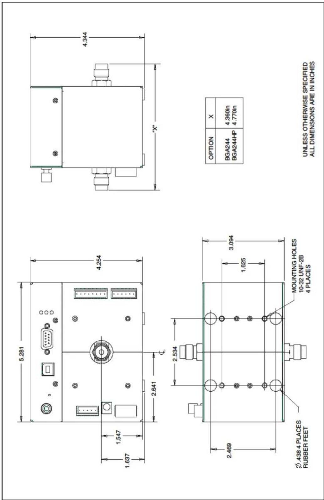
FIGURE 37: BGA244 MECHANICAL DRAWING

FIGURE 38: BGA244E MECHANICAL DRAWING (NO MOUNTING FLANGES)
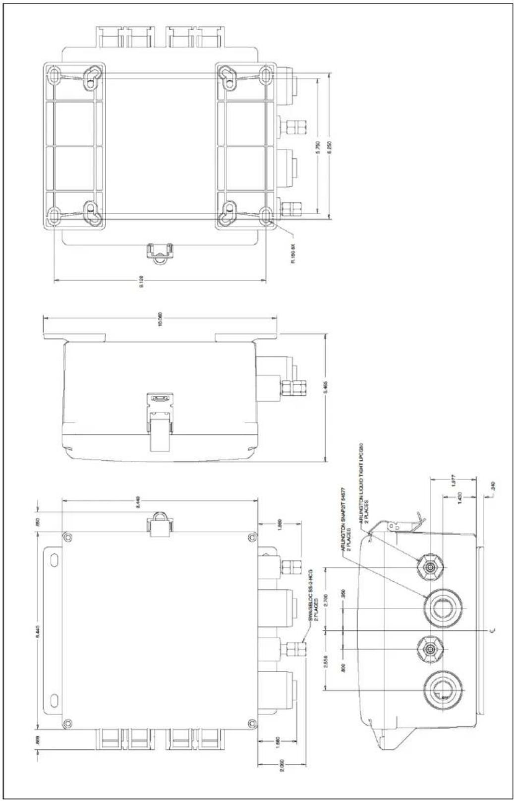
FIGURE 39: BGA244E MECHANICAL DRAWING (WITH MOUNTING FLANGES)
Appendix D: Declaration of Contamination
The repair and/or service of the BGA244, BGA244HP or BGA244E can only be carried out if the declaration of contamination portion of the RMA process has been completed. SRS reserves the right to refuse acceptance of any equipment submitted for repair or service where the declaration has been omitted or has not been fully or correctly completed. SRS also reserves the right to refuse servicing any equipment which could be potentially harmful to the personnel carrying out the repair and service of the equipment. SRS will not accept any equipment which has been radioactively or explosively contaminated without written evidence that such equipment has been properly decontaminated.
Contact SRS if you have any questions regarding the contents of this declaration. The declaration of contamination portion of the RMA requires the following information.
■ Description of the operating environment the instrument was exposed to.
■ Whether the instrument was exposed to potentially harmful substances.
- If exposed to potentially harmful substances, list the following for each substance.
o Chemical Name
o Chemical Formula
o Precautions
- First Aid measures in the event of accident
■ If exposed to potentially harmful substances, were any of the substances:
o Radioactive
o Toxic
o Corrosive
- Explosive
■ If the unit will be decontaminated before shipping to SRS.
■ Confirmation that the information supplied with this form is complete and accurate and that it is shipped in accordance with the appropriate regulations covering Package, Transportation and Labeling of Dangerous Substances.
Appendix E: Installing USB Drivers
In most cases, the USB drivers for the BGA244 should automatically install when the unit is first connected to a Windows computer. However in some cases this may not work due to a lack of internet connection, Windows version or other incompatibility. In these cases the drivers can be manually installed using the following procedure.
The BGA244 uses a FTDI FT220X USB interface chip. FTDI provides USB drivers for several different operating systems. Drivers and their documentation are available on the FTDI website: www.ftdichip.com/FTDrivers.htm
Driver Types
There are two different drivers that can be used to communicate with the BGA244 over USB: VCP and D2XX. Depending on the application only one of the drivers may be required.
VCP or Virtual COM Port makes the BGA244 look like an additional COM port available to the computer. Application software can access the BGA244 in the same way as it accesses any standard COM port. This is commonly used for communications between a user created program and the BGA244.
The D2XX driver gives access the BGA244 through a DLL. Application software can access the BGA244 through a series of function calls. BGAMon uses this driver.
Driver Version
Be sure to install the appropriate driver for your operating system. The FTDI website contains drivers for Windows versions from the present back to Windows 98. Drivers for Linux, MAC and Android are also available.
Driver Installation
Go to www.ftdichip.com/Drivers/VCP.htm or www.ftdichip.com/Drivers/D2XX.htm and download the driver(s) to the computer. If the computer is not connected to the internet download the drivers on a different computer and copy them to a USB thumb drive. Move the thumb drive to the computer that needs the drivers installed.
Go to http://www.ftdichip.com/Support/Documents/InstallGuides.htm and download the appropriate installation guide. Follow the Install Guide instructions to install the drivers.
In some cases Windows may complain that the driver is not certified or verified. If you are certain of the source of the driver, the warning can be ignored and you can continue the installation.
Connect the BGA244 to the computer. The "Found New Hardware" message may appear. Say "No" to Windows Update and instead select "Install Software Automatically".
Contact FTDI if you are unable to successfully install the FTDI USB drivers. Contact information is available at www.ftdichip.com/FTContact.htm
- BGA244 BINARY GAS ANALYZER
- USER MANUAL
- STANFORD RESEARCH SYSTEMS
- CERTIFICATION
- WARRANTY
- SERVICE
- DEDICATION
- CONTENTS
- CHAPTER 1: GETTING STARTED 1
- CHAPTER 2: INSTALLATION GUIDE 13
- TABLE OF CONTENTS II
- PRESSURE TRANSDUCERS 31
- CHAPTER 3: OPERATION GUIDE 35
- BGA244 USER INTERFACE 35
- BINARY GAS ANALYZER 40
- GAS PURITY ANALYZER 44
- PHYSICAL MEASUREMENTS 47
- SCREEN MESSAGES 50
- LED BLINK CODES 53
- CONTROLS 54
- SETUP 58
- CONTROL PANEL 72
- TABLE OF CONTENTS III
- CHAPTER 4: APPLICATION GUIDE 93
- TABLE OF CONTENTS IV
- HIGH PURITY USE 113
- USER GASES 116
- CHAPTER 5: BGAMON 123
- INSTALLATION 124
- USING BGAMON 126
- INSTRUMENT PAGES 129
- LOADING AND SAVING CONFIGURATIONS 142
- UPDATING FIRMWARE 143
- TROUBLESHOOTING BGAMON 144
- CHAPTER 6: REMOTE PROGRAMMING 145
- INTRODUCTION 145
- TABLE OF CONTENTS VI
- INSTALLING BGA-M 206
- MAINTENANCE 207
- CALIBRATION 210
- PERFORMANCE VERIFICATION 210
- CHAPTER 8: CIRCUIT DESCRIPTION 217
- OVERVIEW 217
- DETAILED CIRCUIT DESCRIPTION 219
- APPENDIX A: GAS TABLE 235
- FACTORY GAS TABLE 235
- GAS TABLE PROPERTIES 246
- APPENDIX B: BGA244E 257
- UNPACKING 259
- QUICK START 259
- INSTALLATION 260
- APPENDIX C: MECHANICAL DRAWINGS 265
- APPENDIX D: DECLARATION OF CONTAMINATION 269
- TABLES
- FIGURES
- SAFETY PROCEDURES AND PRECAUTIONS
- DO NOT SUBSTITUTE PARTS OR MODIFY THE INSTRUMENT
- SERVICE BY QUALIFIED PERSONNEL ONLY
- USE CAUTION WHEN OPERATING WITH HAZARDOUS MATERIALS
- PURGE THE INSTRUMENT
- USE PROPER PROCEDURES WHEN PURGING
- EXPLOSIVE ENVIRONMENT WARNING
- USE PROPER FITTINGS AND TIGHTENING PROCEDURES
- CHECK FOR LEAK-TIGHT FITTINGS
- OPERATE AT SAFE INLET PRESSURES
- INSTALL A SUITABLE BURST DISK
- KEEP THE UNIT FREE OF CONTAMINATION
- ALLOW PROPER WARM UP TIME
- GROUNDING
- COVERS
- RETURNS
- SYMBOLS YOU MAY FIND ON SRS PRODUCTS
- SPECIFICATIONS
- OPERATIONAL
- MEASUREMENT
- EVENT RELAY (REQUIRES 24V)
- COMPUTER I/O
- RS-232
- USB
- RS-422 (REQUIRES 24V)
- POWER
- 24 V
- ENVIRONMENT
- PHYSICAL
- BGA244E
- MANUAL CONVENTION
- [KEY]
- [ON|OFF]
- [ESC]
- ○ CHOICE
- CHOICE
- (HOME/HERE/OVER_THERE)
- [HOME]
- [←] OR [BACK]
- [HELP]
- UNIT CONVENTIONS AND ABBREVIATIONS
- NORMAL TEMPERATURE AND PRESSURE (NTP)
- FLOW
- SPEED OF SOUND
- NORMALIZED SPEED OF SOUND
- PRESSURE
- HOW THIS MANUAL IS ORGANIZED
- TRADEMARKS
- CHAPTER 1: GETTING STARTED
- BINARY GAS ANALYZERS
- WHAT IS A BINARY GAS ANALYZER
- USES FOR BINARY GAS ANALYZERS
- FEATURES AND ACCESSORIES
- BGA244
- BGA244HP
- DISPLAY
- ELECTRICAL CONNECTIONS
- ACCESSORIES
- 24V POWER SUPPLY (BGA-24)
- SHIELD (BGA-S)
- METAL COVER (BGA-M)
- GAS FITTING ADAPTERS
- UNPACKING
- BEFORE YOU OPEN THE BOX
- WHAT IS INCLUDED WITH THE BGA244
- ACCESSORIES (IF ORDERED)
- WHAT IS INCLUDED WITH THE BGA244HP
- QUICK START
- QUICK TEST
- INSTALLATION AND CONFIGURATION
- WINDOWS DRIVERS FOR THE BGA244
- CHAPTER 2: INSTALLATION GUIDE
- OPERATING ENVIRONMENT
- TEMPERATURE
- GAS
- ELECTRICAL AND MAGNETIC FIELDS
- ACCESS
- FRONT PANEL
- WRENCH CLEARANCE
- CABLE CLEARANCE
- VENTILATION CLEARANCE
- SERVICE ACCESS
- INSTALLATION
- PROCEDURE
- GAS FITTINGS
- INSTALLATION GUIDELINES
- ELECTRICAL NOISE PRECAUTIONS
- ELECTRICAL CONNECTORS
- CONNECTOR PINOUTS
- TERMINAL STRIP CONNECTORS
- USB POWER
- USB POWER CABLES
- ALL USB CABLES ARE NOT CREATED EQUAL
- 24V POWER
- BGA-24 USB POWER SUPPLY
- COMPUTER INTERFACES
- RS-422
- ANALOG I/O CONNECTIONS
- ANALOG OUTPUT
- VOLTAGE OUTPUTS
- CURRENT OUTPUTS
- ANALOG INPUT
- VOLTAGE INPUT
- CURRENT INPUT
- CURRENT WITH LOOP POWER VOLTAGE SOURCE
- EVENT RELAYS
- PRESSURE TRANSDUCERS
- MOUNTING LOCATION
- TYPES OF PRESSURE TRANSDUCERS
- VOLTAGE OUTPUT TRANSDUCERS
- CURRENT OUTPUT TRANSDUCERS
- TRANSDUCERS WITH EXTERNAL POWER SUPPLIES
- TRANSDUCERS WITH LOOP POWER
- CHAPTER 3: OPERATION GUIDE
- BGA244 USER INTERFACE
- NAVIGATION
- HELP SCREENS
- POWER ON
- APPEARANCE
- MEASUREMENT SECTION
- CONTROL SECTION
- INSTRUMENT MODES
- SELECT INSTRUMENT MODE
- BINARY GAS ANALYZER
- PRINCIPLE OF OPERATION
- DETAILS
- RANGE
- SELECTING GASES
- MOLAR FRACTION VS MASS FRACTION
- ACCURACY ESTIMATOR
- REL
- DUAL CONCENTRATIONS
- GAS PURITY ANALYZER
- SELECT GAS
- PHYSICAL MEASUREMENTS
- SCREEN MESSAGES
- ANALYSIS MESSAGES
- DEGAS ON
- NO SIGNAL
- INVALID
- BAD PRESSURE
- CONDENSATION
- INVALID GAS MESSAGE
- OTHER MESSAGES
- TWO SOL
- SYSTEM FAULT
- ALERT
- STOPPED
- INVALID ENTRY
- LED BLINK CODES
- NORMAL BEHAVIOR
- ERROR LED CODES
- POWER LED CODES
- CONTROLS
- LIMITS
- PROCESS LIMITS PAGE
- EXAMPLE
- SCALE (BINARY & GAS PURITY)
- PRESSURE (PHYSICAL MEASUREMENTS)
- HELP
- EVENT RELAY 1 & 2
- EVENT RELAY CONFIGURATION PAGES
- FORCE ON, FORCE OFF BUTTONS
- EVENT RELAY CONNECTIONS
- USING EVENT RELAYS
- SETUP
- RUN|STOP
- INSTRUMENT MODE
- HOW TO SELECT GASES
- SWAP GASES
- REFERENCE GAS (GAS PURITY ANALYZER)
- GAS PURITY
- GAUGE PRESSURE VS ABSOLUTE PRESSURE
- SELECTING ANALYSIS PRESSURE
- USER PRESSURE
- CONFIGURE PRESSURE GAUGE
- CONFIGURE INPUT
- PRESSURE METER
- STORE|RECALL
- SETUP LIST
- STORE
- RECALL
- ERASE
- DEFAULT SETUP
- FACTORY SETUP
- CONTROL PANEL
- DISPLAY ORIENTATION
- BACKLIGHT INTENSITY
- KEY CLICK
- SCREEN CALIBRATION
- UNITS
- RATIO
- SPEED
- AVERAGES 10
- AVERAGING
- AMPLITUDE
- BINARY GAS CONCENTRATION
- RELAXATION CORRECTION
- STATUS
- LIST OF MONITORED PARAMETERS
- HEATER
- BLOCK HEATER
- DEGAS HEATER
- RECEIVE AND TRANSMIT BUFFERS
- BITS 8
- ANALOG I/O
- ANALOG INPUTS
- ANALOG OUTPUTS
- MEASURE OUTPUT
- OUTPUT 1 AND OUTPUT 2
- FAULTS
- EXTERNAL POWER SUPPLY FAULTS
- GENERAL SYSTEM FAULTS
- SELF TEST FAULT
- FAULTS PAGE
- ALERTS
- ANALOG I/O ALERTS
- TEMPERATURE ALERTS
- GENERAL ALERTS
- ALERTS PAGE
- ALERT ACTIONS
- MESSAGE LOG
- SELF TEST
- RUNNING SELF TEST
- PASSWORD
- ABOUT THE BGA244
- HARDWARE RESET
- NORMAL RESET
- HARD RESET
- FACTORY SAFE MODE
- USER GASES
- UPDATING FIRMWARE
- CHAPTER 4: APPLICATION GUIDE
- GASES
- GAS REQUIREMENTS
- SUPPORTED GASES
- GASES THAT SHOULD BE USED WITH CAUTION
- EXPLOSIVE OR FLAMMABLE MIXTURES
- CORROSIVE MIXTURES
- UNUSUAL GAS PROPERTIES
- RELAXATION EFFECT
- REACTIVE OR DIMERIZING GASES
- CONDENSATION WARNING
- AVOIDING CONDENSATION
- WATER VAPOR IN AIR
- WATER VAPOR IN OTHER GASES
- OPERATING PRESSURE
- PRESSURE EFFECTS IN GASES
- IS PRESSURE INFORMATION NECESSARY
- ESTIMATING PRESSURE
- COMPENSATING USING REL
- MINIMUM OPERATING PRESSURES
- AMBIENT PRESSURE VARIATION
- OPERATING CONDITIONS
- WARM UP TIME
- RESPONSE TIME
- HIGH FLOW RATE
- TRANSIENTS
- INTERFERENCE
- VIBRATION
- ELECTRICAL AND MAGNETIC INTERFERENCE
- MEASUREMENTS
- TEMPERATURE VARIATIONS
- EVACUATING CELL
- USING AVERAGING
- REL TO A REFERENCE GAS
- BINARY GAS ANALYZER VS GAS PURITY ANALYZER
- WHEN TO USE THE BINARY GAS ANALYZER
- WHEN TO USE THE GAS PURITY ANALYZER
- CONVERTING MOLAR FRACTION VS MASS FRACTION
- ACCURACY & STABILITY
- SPEED OF SOUND MEASUREMENT
- TEMPERATURE MEASUREMENT
- GAS TABLE DATA
- USING REL TO IMPROVE ACCURACY
- ESTIMATED ACCURACY
- BINARY GAS MEASUREMENT ACCURACY
- POOR SENSITIVITY
- PROBLEM MIXTURES
- GAS PURITY MEASUREMENT ACCURACY
- LONG TERM STABILITY
- HIGH PURITY USE
- FITTINGS AND TUBING
- LEAK TESTING
- DEAD VOLUMES
- OUTGASSING
- DEGAS
- UNDER VACUUM
- WHILE FLOWING GAS
- FACTORY GAS TABLE
- USER GAS TABLE
- SELECTING A USER GAS
- USER GAS PARAMETERS
- MASS
- Y
- ADDING A USER GAS WITH BGAMON
- ADDING A USER GAS OVER A COMPUTER INTERFACE
- ADDING GASES
- EXAMPLE: ADDING A SINGLE SPECIES GAS (ARGON)
- EXAMPLE: ADDING A BLENDED GAS (AIR)
- EXAMPLE: ADDING A BLENDED GAS (HELIOX)
- OPERATING WITH USER GASES
- USING REL WITH USER GASES
- CHAPTER 5: BGAMON
- DRIVERS
- DOWNLOADING BGAMON
- BGAMON QUICK START
- USING BGAMON
- MENU BAR
- FILE
- DEVICE
- PAGE
- UTILITIES
- SYSTEM AREA
- FAULT
- RUNNING
- CONNECT OR DISCONNECT
- AUTOSAVE
- INSTRUMENT PAGE
- STATUS BAR
- INSTRUMENT PAGES
- SNAPSHOT
- UNIT FAMILIES
- HEATER CONTROL
- EVENTS
- STRIP CHART
- GRAPH
- TIME AXIS
- Y AXIS
- CURSOR
- PRINTING
- EXPORT
- GAS SELECTION
- SET GASES
- ADDING AND REMOVING USER GASES
- FAULTS/ALERTS
- STORE / RECALL
- LOADING AND SAVING CONFIGURATIONS
- PROBLEMS DURING UPDATE
- TROUBLESHOOTING BGAMON
- CONNECTING
- RUNNING SLOWLY
- CHAPTER 6: REMOTE PROGRAMMING
- INTRODUCTION
- INTERFACE CONFIGURATION
- FRONT-PANEL INDICATORS
- TRANSMIT AND RECEIVE BUFFERS
- BREAK SIGNAL
- USB CONFIGURATION
- RS-232 CONFIGURATION
- RS-422 CONFIGURATION
- COMMAND SYNTAX
- DO NOT SEND () OR {} OR [ ] AS PART OF THE COMMAND
- ERRORS
- PARAMETER CONVENTIONS
- NUMERIC CONVENTIONS
- MEASUREMENT ERRORS
- MISSING POWER SUPPLIES
- ABRIDGED INDEX OF COMMANDS
- DETAILED COMMAND LIST
- COMMON IEEE-488.2 COMMANDS
- CAL? AUTO CALIBRATION
- CLS CLEAR STATUS
- ESE(?){I} STANDARD EVENT STATUS ENABLE
- ESR? STANDARD EVENT STATUS REGISTER
- IDN? IDENTIFICATION STRING
- OPC(?)
- OPERATION COMPLETE
- PSC(?){I}
- POWER-ON STATUS CLEAR
- RCL I RECALL INSTRUMENT SETTINGS
- RST RESET THE INSTRUMENT
- SAV I SAVE INSTRUMENT SETTINGS
- SRE(?){I} SERVICE REQUEST ENABLE
- STB? STATUS BYTE
- BIT MEANING
- TRG TRIGGER
- TST? SELF TEST
- WAI WAIT FOR COMMAND EXECUTION
- INSTRUMENT STATUS COMMANDS
- INSTRUMENT STATUS REGISTERS
- ANAI?[I]
- ANALOG STATUS REGISTER (IMMEDIATE)
- ANAR?[I]
- ANALOG STATUS REGISTER (LATCHED)
- BG0E(?){I}
- BGA ENABLE STATUS REGISTER 0
- BG0I?[I]
- BGA STATUS REGISTER 0 (IMMEDIATE)
- BG0R?[I]
- BGA STATUS REGISTER 0 (LATCHED)
- BG1E(?){I}
- BGA STATUS ENABLE REGISTER 1
- BG1I?[I]
- BGA STATUS REGISTER 1 (IMMEDIATE)
- BG1R?[I]
- BGA STATUS REGISTER 1 (LATCHED)
- FALE(?){I} FAULT ENABLE REGISTER
- FALI?[I]
- FAULT STATUS REGISTER (IMMEDIATE)
- FALR?[I]
- FAULT STATUS REGISTER (LATCHED)
- INTERFACE COMMANDS
- BAUD(?)I{,J} SET BAUD RATE
- LERR? INSPECT ERROR BUFFER
- UARE(?)I{,J} ENABLE COMPUTER INTERFACE
- XTRM I{,J,K} INTERFACE TERMINATOR
- MEASUREMENT AND RELATED COMMANDS
- NSOS?[U] NORMALIZED SPEED OF SOUND
- PRES?[U] ANALYSIS PRESSURE
- PUDL?[U] PURITY MODE MEASUREMENT
- RATO? I[U]
- BINARY GAS RATIO MEASUREMENT
- RAT2? I[U] BINARY GAS RATIO 2
- ND MEASUREMENT
- SSOS?[U] MEASURED SPEED OF SOUND
- TCEL?[U] CELL TEMPERATURE
- XALL? QUERY ALL
- RELATED COMMANDS
- RELH REL TO 100
- RELM(?) REL MODE
- RELV(?){R}[U] REL VALUE
- RELZ REL TO ZERO
- RELX(?){I} RELAXATION CORRECTION
- RUNM(?){I} RUN MODE
- SETT
- AVERAGED MEASUREMENT SETTLED
- UNCT?[U] MEASUREMENT UNCERTAINTY
- LIME(?)I,J{,K}
- LIMIT ENABLE
- CONFIGURATION COMMANDS
- GAS SELECTION COMMANDS
- GASP(?){S}
- SET PRIMARY GAS
- GASS(?){S}
- SET SECONDARY GAS
- SWAP SWAP BINARY GASES
- HEATER COMMANDS
- BLTM?[U] ENDPLATE TEMPERATURE
- HEDG(?){I} DEGAS HEATER ENABLE
- HEEN(?){I}
- BLOCK HEATER ENABLE
- HEIL(?){D} MAXIMUM HEATER CURRENT
- HEPW? HEATER POWER
- HEST
- BLOCK HEATER STATUS
- PRESSURE COMMANDS
- PRSU(?)I{,J} PRESSURE MEASUREMENT SCALE UNITS
- PUSR(?){P}[U] USER CELL PRESSURE
- ANALOG I/O COMMANDS
- MEASURE ANALOG OUTPUT COMMANDS
- MOCN(?){I} MEASURE OUT CONCENTRATION
- MOEN(?){I} MEASURE OUT ENABLE
- MOMN(?)I{,D}[U] MEASURE OUT SCALE MIN
- MOMX(?)I{,D}[U] MEASURE OUT SCALE MAX
- MOTY(?){I} MEASURE OUT TYPE
- MOVA? MEASURE OUT VALUE
- ANALOG OUTPUT COMMANDS
- AOEN(?)I{,J} ANALOG OUT ENABLE
- AOMN(?)I,J{,D}[U]
- ANALOG OUT SCALE MIN
- AOMX(?)I,J{,D}[U]
- ANALOG OUT SCALE MAX
- ANALOG INPUTS COMMANDS
- AILP(?)I{,D}
- ANALOG LOOP POWER VOLTAGE
- AINE(?)I{,J}
- ANALOG INPUT ENABLE
- AIRE?I READ ANALOG INPUT
- AITY(?)I{,J} ANALOG INPUT TYPE
- MISCELLANEOUS COMMANDS
- ATSV AUTOSAVE
- AUSRI,J,S ADD USER GAS
- BAKL(?){I} BACKLIGHT
- DSPO(?){I} DISPLAY ORIENTATION
- DUSRS DELETE USER GAS
- HOME GO TO HOME PAGE
- ERAS I ERASE STORED SETTING
- EXPA? EXTERNAL POWER AVAILABLE
- MUTE(?){I}
- KEYCLICK MUTE
- PASE(?){I} PASSWORD ENABLE
- PASL? PASSWORD LOCKED STATUS
- PASS(?){I} PASSWORD
- PCTM?[U] PCB TEMPERATURE
- SGAM(?){I}
- SET SPEAKER AMPLITUDE MODE
- UNFA(?)I{,S} GLOBAL UNITS
- VOLT? I EXTERNAL POWER VOLTAGE
- STATUS BYTE DEFINITIONS
- POWER ON BEHAVIOR OF STATUS REGISTERS
- INSTRUMENT STATUS REGISTER MODEL
- EVENT STATUS REGISTER
- ERROR CODES
- EXECUTION ERRORS
- 0 NO ERROR
- 10 ILLEGAL VALUE
- 11 ILLEGAL MODE
- 12 FLASH READ ERROR
- 13 RECALL FAILED
- 14 FLASH WRITE ERROR
- 15 FLASH ERASE ERROR
- 18 NO 24V AVAILABLE
- 19 CAL ERROR
- 20 FIRMWARE ERROR
- 21 TIME OUT ERROR
- 22 BINARY STREAM ERROR
- 23 ILLEGAL GAUGE
- 24 OUTPUT ERROR
- 25 INPUT ERROR
- 26 INVALID GAS
- 27 NOT ALLOWED
- QUERY ERRORS
- 30 LOST DATA
- PARSING OR COMMAND ERRORS
- 110 ILLEGAL COMMAND
- 111 UNDEFINED COMMAND
- 112 ILLEGAL QUERY
- 113 ILLEGAL SET
- 114 NULL PARAMETER
- 115 EXTRA PARAMETERS
- 116 MISSING PARAMETERS
- 117 PARAMETER OVERFLOW
- 118 INVALID FLOATING POINT NUMBER
- 120 INVALID INTEGER
- 121 INTEGER OVERFLOW
- 122 INVALID HEXADECIMAL
- 126 SYNTAX ERROR
- 127 ILLEGAL UNITS
- 128 MISSING UNITS
- COMMUNICATION ERRORS
- 170 COMMUNICATION ERROR
- 171 OVER RUN
- OTHER ERRORS
- 254 TOO MANY ERRORS
- USING THE USB DRIVERS
- DRIVERS FOR OTHER OPERATING SYSTEMS
- TROUBLESHOOTING
- POWER LED
- ERROR LED
- LCD DISPLAY NOT ACTIVE
- SELF TEST FAIL
- SELF TESTS
- SYSTEM FAULTS
- FIRMWARE UPDATE
- STORED SETUP
- FIRMWARE ERROR
- LOCKED
- STORE AND RECALL FAILURE
- TOUCHSCREEN PROBLEMS
- INSTALLING BGA-M
- MAINTENANCE
- REPLACING GAS FITTINGS
- REMOVAL GUIDELINES
- REPLACING GAS FITTINGS FOR THE BGA244E
- TERMINAL STRIPS
- CLEANING
- CALIBRATION
- PERFORMANCE VERIFICATION
- ANALOG I/O ACCURACY
- REQUIRED EQUIPMENT
- ANALOG MEASURE OUTPUT
- ANALOG INPUTS AND OUTPUTS 1 & 2
- MEASUREMENT ACCURACY
- CHAPTER 8: CIRCUIT DESCRIPTION
- OVERVIEW
- BLOCK DIAGRAM
- SIGNAL PROCESSING ALGORITHM
- DETAILED CIRCUIT DESCRIPTION
- MAIN CIRCUIT BOARD
- SCHEMATIC 2: DSP & BYPASS
- SCHEMATIC 3: MEMORY, COMMUNICATIONS AND RESET
- SCHEMATIC 4: CODEC, AUX ADC AND REFERENCE
- SCHEMATIC 5: USER INTERFACE AND END BOARD CONNECTORS
- SCHEMATIC 6: POWER SUPPLIES
- MICROPHONE BOARD
- SCHEMATIC 7: TEMPERATURE SENSE & HEATERS
- TEMPERATURE SENSE
- SCHEMATIC 8: PREAMP AND TRANSDUCER SENSORS
- PREAMP
- TRANSDUCER SENSORS
- SPEAKER BOARD
- SCHEMATIC 9: TEMPERATURE SENSE & HEATERS
- SCHEMATIC 10: OUTPUT AMPLIFIER AND TRANSDUCER SENSORS
- OUTPUT AMPLIFIER
- INDUSTRIAL BOARD
- SCHEMATIC PAGE 11
- CONTROL BOARD
- SCHEMATIC PAGE 12: ANALOG OUTPUTS 1 & 2
- SCHEMATIC PAGE 13: ANALOG INPUT 1
- SCHEMATIC PAGE 14: ANALOG INPUT 2
- SCHEMATIC PAGE 15: RELAYS AND I/O CONTROL
- APPENDIX A: GAS TABLE
- GAS TABLE PROPERTIES
- CAS REGISTRY NUMBER (COLUMN 1)
- PREFERRED NAME (COLUMN 2)
- FIRST AND SECOND ALTERNATE NAMES (COLUMN 3 & 4)
- FORMULA (COLUMNS 5)
- SOURCE OF DATA
- CORRESPONDING STATES PRINCIPLE (CSP)
- MOLAR MASS (COLUMN 6)
- ISOBARIC HEAT CAPACITY, CP/R (COLUMNS 7-12)
- SPEED OF SOUND AT NORMAL TEMPERATURE (COLUMN 13)
- TSONOPOULOS CORRELATION
- CRITICAL CONSTANTS (COLUMNS 13-17)
- ACENTRIC FACTOR (COLUMN 18)
- DIPOLE MOMENT (COLUMN 19)
- CHEMICAL FAMILY (COLUMN 19)
- TSONOPOULOS A,B PARAMETERS (COLUMN 20-21)
- SECOND VIRIAL COEFFICIENT PARAMETERS (COLUMN 23-25)
- THIRD VIRIAL COEFFICIENT PARAMETERS (COLUMN 26-30)
- VISCOSITY (COLUMNS 31-33)
- THERMAL CONDUCTIVITY (COLUMNS 34-36)
- HEAT CAPACITY RELAXATION PARAMETERS (COLUMNS 37-40)
- VAPOR PRESSURE (COLUMNS 41-43)
- SPEED OF SOUND OFFSETS (COLUMNS 44-46)
- REFERENCES
- APPENDIX B: BGA244E
- TYPE 6 (WITH COVER LATCHED)
- TYPE 6P (WITH COVER SCREWS INSTALLED)
- OPERATION
- WHAT IS INCLUDED WITH THE BGA244E
- MOUNTING
- DIRECT MOUNT
- FLANGE MOUNTING
- CONDUIT
- ELECTRICAL
- APPENDIX C: MECHANICAL DRAWINGS
- APPENDIX D: DECLARATION OF CONTAMINATION
- APPENDIX E: INSTALLING USB DRIVERS
- DRIVER TYPES
- DRIVER VERSION
- DRIVER INSTALLATION
Brand : SRS
Model : BGA244
Category : Gas detector