
RLT254SDSO - Hedge Trimmers RYOBI - Free user manual and instructions
Find the device manual for free RLT254SDSO RYOBI in PDF.


| Product Type | Hedge Trimmer |
| Brand | RYOBI |
| Model | RLT254SDSO |
| Engine Displacement | 25.4 cc |
| Engine Type | 2-Stroke Petrol |
| Cutting Length | 60 cm |
| Blade Material | High Carbon Steel |
| Blade Gap | 28 mm |
| Weight (without fuel) | 5.2 kg |
| Overall Length | 105 cm |
| Fuel Tank Capacity | 0.4 L |
| Anti-Vibration System | Yes |
| Ergonomic Handle | Soft Grip, Adjustable |
| Safety Guard | Hand Guard Included |
| Noise Level | 96 dB(A) (uncertainty K=3 dB) |
| Vibration Level (front handle) | 4.2 m/s² |
| Vibration Level (rear handle) | 3.8 m/s² |
| Ignition System | Electronic |
| Fuel Mix Ratio | 50:1 (Petrol:2-Stroke Oil) |
| Spark Plug | Champion RCJ6Y or equivalent |
| Operation | Single Operator |
Frequently Asked Questions - RLT254SDSO RYOBI
User questions about RLT254SDSO RYOBI
0 question about this device. Answer the ones you know or ask your own.
Ask a new question about this device
Download the instructions for your Hedge Trimmers in PDF format for free! Find your manual RLT254SDSO - RYOBI and take your electronic device back in hand. On this page are published all the documents necessary for the use of your device. RLT254SDSO by RYOBI.
USER MANUAL RLT254SDSO RYOBI
RLT254CDSO RLT254SDSO
ORIGINAL INSTRUCTIONS
Grass Trimmer
HERO SHOT TO FOLLOW ONCE AVAILABLE
Important!
It is essential that you read the instructions in this manual before assembling, operating, and maintaining the product.
Subject to technical modification.
Safety, performance, and dependability have been given top priority in the design of your grass trimmer.
INTENDED USE
The grass trimmer is intended to be used only by adults who have read and understood the instructions and warnings in this manual and can be considered responsible for their actions. The product is only intended for use outdoors in a well-ventilated area. For safety reasons, the product must be adequately controlled by a two-handed operation.
The product is designed for cutting grass, light weeds, and other similar vegetation at or about ground level. The cutting plane should be approximately parallel to the ground surface.
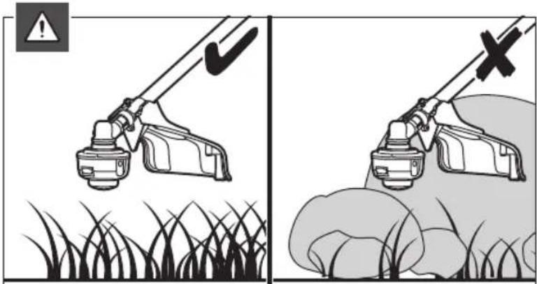
The product should not be used to cut or trim hedges, bushes, or other vegetation where the cutting plane is not or about ground surface level.
Do not use the product for any other purpose.
WARNING
To reduce the risk of injury, the user must read and understand the operator's manual.
WARNING
Do not attempt to operate the product until you have read thoroughly and understood completely all instructions and safety rules contained in this manual. Failure to comply may result in accidents involving fire, electric shock, or serious personal injury. Save the operator's manual and review frequently for continuing safe operation and instructing others who may use the product.
WARNING
The product is not intended to be used by children or persons with reduced physical, mental, or sensory capabilities. Children should be adequately supervised to ensure they do not play with the product.
GENERAL SAFETY WARNINGS
■ For safe operation, read and understand all instructions before using the product. Follow all safety instructions. Failure to follow all safety instructions listed below, can result in serious personal injury.
■ Some regions have regulations that restrict the use of the product. Check with your local authority for advice.
■ Do not allow children or untrained individuals to use the product.
■ Never start or run the engine in a closed or poorly ventilated area; breathing exhaust fumes can kill.
- Clear the work area before each use. Remove all objects such as rocks, broken glass, nails, wire, or string that can be thrown or become entangled in the string head.
■ Wear full eye and hearing protection while operating the product. If working in an area where there is a risk of falling objects, head protection must be worn.
■ Hearing protection may restrict the operator's ability
to hear warning sounds. Pay particular attention to potential hazards around and inside the working area.
■ Wear heavy, long trousers, non-slip protective footwear, and gloves. Do not wear loose fitting clothing, short trousers, jewellery of any kind, or use with bare feet.
- Secure long hair so it is above shoulder level to prevent entanglement in any moving parts.
- Keep all bystanders, children, and pets at least 15 m away. Stop the product if anyone enters the area.
■ Do not use the product when tired, ill, under medication, or under the influence of alcohol and drugs.
- Do not use in poor lighting. The operator needs clear unrestricted vision to identify potential hazards.
- Keep firm footing and balance at all times. Do not overreach. Overreaching can result in loss of balance or exposure to hot surfaces.
- Keep all parts of your body away from any moving part.
- Do not touch the area around the silencer or cylinder of the product, these parts get hot from operation.
■ Always stop the engine and allow it to cool down before making any adjustments.
- Do not smoke when mixing the fuel or when filling the fuel tank.
■ Mix and store the fuel in a container that is approved for fuel.
- Mix the fuel outdoors where there are no sparks or flames. Wipe up any fuel spillage. Move 9 m away from refueling site before starting engine.
■ Stop the engine and allow it to cool down before refueling or storing the product.
- Allow the engine to cool down; empty the fuel tank and secure the product from moving before transporting in a vehicle.
■ Turn off the engine. Make sure all moving parts have come to a complete stop:
- before servicing
• before clearing a blockage
- before checking, cleaning, and working on the product
• before changing accessories
● after striking a foreign object
- whenever leaving the product unattended
• whenever performing maintenance
- whenever the product starts to vibrate abnormally
WARNING
Never use cutting means or attachments which are not specified by RYOBI in this manual. This includes the use of metal multi-piece pivoting chains and flail-blades. These items are known to break up during use and present a high risk of serious injury to the operator or bystanders.
WARNING
Inspection after dropping or other impacts: Thoroughly inspect the product and identify any problems or damage to it. Any part that is damaged should be properly repaired or replaced by an authorised service centre.
GRASS TRIMMER SAFETY WARNINGS
- Replace the string head if cracked, chipped, or damaged in any way. Be sure the string head is properly installed and securely fastened. Failure to do so can cause serious injury.
■ Avoid using on wet grass.
■ Do not walk backwards when using the product.
■ Walk, never run.
The small blade fitted to the cutting attachment guard is designed to trim the new extended line to the correct length for safe and optimum performance. It is very sharp; do not touch it, particularly when cleaning the product.
■ Always ensure that ventilation openings are kept clear of debris.
■ Before use and after any impact, check that there are no damaged parts. Examine the cutting means for signs of cracking or other damage. A defective switch or any part that is damaged should be properly repaired or replaced by an authorised service facility.
■ Make sure the head attachment is properly installed and securely fastened.
■ Make sure all guards, deflectors, handles, bolts, and fasteners are properly and securely attached. - Do not modify the product in any way. This may increase the risk of injury to yourself or others.
- Use only the manufacturer's replacement line in the cutting head. Do not use any other cutting attachment.
■ Never use the product without the cutting attachment. - Maintain a firm grip on both handles while trimming. Keep string head below waist level. Never cut with the string head located more than 76 cm above the ground.
TRANSPORTATION AND STORAGE
■ Stop the engine and allow it to cool down before storing or transporting.
■ Clean all foreign materials from the product.
- Drain all fuel from tank into a container approved for petrol. Remember to properly replace and tighten the fuel cap.
■ Run the engine until it stops, this will remove all fuel that could become stale and leave varnish and gum in the fuel system.
■ Store the product in a cool, dry, and well-ventilated place that is inaccessible to children. Keep away from corrosive agents, such as garden chemicals and deicing salts. Do not store outdoors.
■ When transporting the product in a vehicle, secure it against movement or falling to prevent injury to persons or damage to the product.
■ Never carry or transport the product while the engine is running.
- Abide by all government and local regulations for the safety storage and handling of petrol.
Storage (1 month or longer)
- Drain all fuel from tank into a container approved for fuel. Run engine until it stops.
■ Clean all foreign material from the product. Store it in a well-ventilated place that is inaccessible to children.
- Keep away from corrosive agents such as garden chemicals and de-icing salts.
■ Abide by all ISO and local regulations for the safe storage and handling of fuel. Excess fuel should be used in other 2-cycle engine powered equipment
Short term
■ Stop the engine and allow it to cool down before storing.
■ Clean all foreign material from the product.
■ Store the product in a cool, dry, and well-ventilated place that is inaccessible to children.
- Keep away from corrosive agents such as garden chemicals and de-icing salts.
■ Do not store outdoors.
MAINTENANCE
WARNING
Use only original manufacturer's replacement parts, accessories, and attachments. Failure to do so can cause possible injury, contribute to poor performance, and may void your warranty.
■ Always stop the engine and allow it cool down before making any maintenance.
- You may make adjustments and repairs described in this manual. For other repairs, contact an authorised service centre.
■ Consequences of improper maintenance may include excess carbon deposits resulting in loss of performance and discharge of black lubricant residue dripping from the silencer.
■ For the replacement line, use only nylon filament line of the diameter described in the specification table of this manual.
■ After extending the new cutter line, always return the product to its normal operating position before starting.
■ After each use, clean the product with a soft, dry cloth.
■ Any part that is damaged should be properly repaired or replaced by an authorised service centre.
- Check all nuts, bolts, and screws at frequent intervals for proper tightness to ensure the product is in a safe working condition.
RESIDUAL RISKS
Even when the product is used as prescribed, it is still impossible to completely eliminate certain residual risk factors. The following hazards may arise during use, and the operator should pay special attention to avoid the following:
■ injury caused by vibration
– Hold the product by designated handles and restrict working time and exposure.
■ injury caused by exposure to noise
– Wear hearing protection and limit exposure.
■ injury caused by flying debris
– Wear eye protection at all times.
RISK REDUCTION
It has been reported that vibrations from handheld tools may contribute to a condition called Raynaud's Syndrome. Symptoms may include tingling, numbness and blanching of the fingers, usually apparent upon exposure to cold. Hereditary factors, exposure to cold and dampness, diet, smoking and work practices are all thought to contribute to the development of these symptoms. There are measures that can be taken by the operator to possibly reduce the effects of vibration:
- Keep your body warm in cold weather. When operating the product, wear gloves to keep the hands and wrists warm. It is reported that cold weather is a major factor contributing to Raynaud's Syndrome.
■ After each period of operation, exercise to increase blood circulation.
■ Take frequent work breaks. Limit the amount of exposure per day.
If you experience any of the symptoms of this condition, immediately discontinue use and see your physician.
WARNING
Injuries may be caused, or aggravated, by prolonged use of a tool. When using any tool for prolonged periods, ensure you take regular breaks.
WHAT'S IN THE BOX
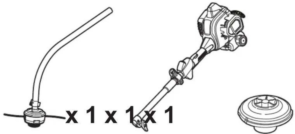
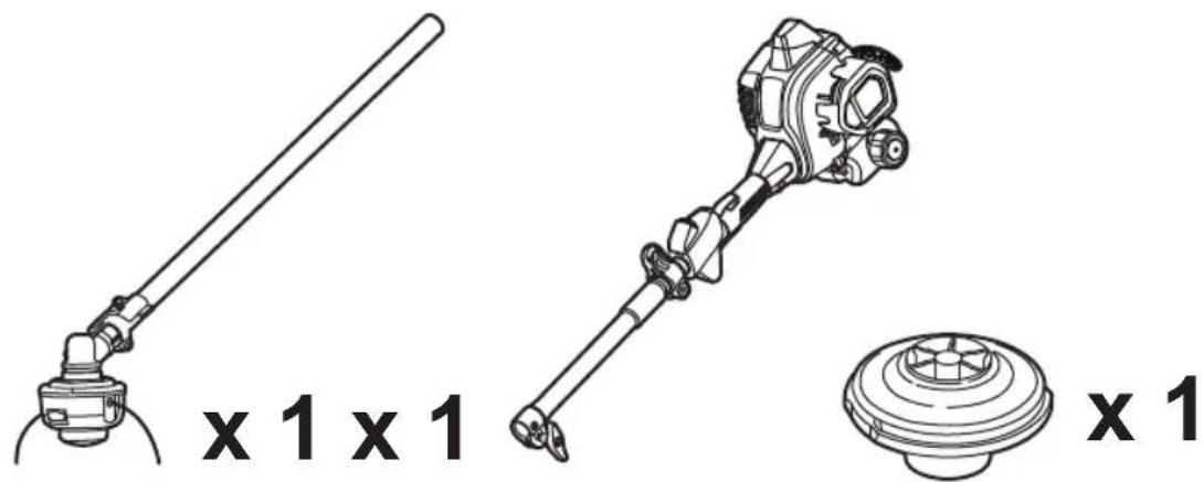
■ Powerhead and upper boom assembly x 1
■ Lower boom and string head assembly x 1
■ Front handle assembly x 1
■ Grass deflector x 1
■ PRO CUT II string head x 1
■ Retainer knob x 1
■ Cutting line x 10 pcs
■ Speedwinder handle x 1
■ Ethanol shield 2 cycle lubricant x 1
■ Combination wrench x 1
■ Harness x 1
■ Drive shaft x 1
■ Operator's manual x 1
■ Stamping wrench (RLT254CDSO only) x 1
SYMBOLS ON THE PRODUCT
| Safety alert | |
| Read and understand all instructions before operating the product, follow all warnings and safety instructions. |





Wear eye, hearing and head protection when operating the product.
Wear non-slip safety footwear when using the product.
Wear non-slip, heavy-duty gloves.
Beware of thrown or flying objects. Keep all bystanders, especially children and pets, at least 15 m away from the operating area
The product is not intended for use with a toothed saw type blade.
Do not use metal blade (s) on the product
RLT254CDSO: Rotational direction and maximum speed of the shaft for the cutting attachment.
RLT254SDSO: Rotational direction and maximum speed of the shaft for the cutting attachment.
Use unleaded gasoline intended for motor vehicle use with an octane rating of 91 ([R+M]/2) or higher.
Use full synthetic 2-stroke lubricant for air cooled engines.
Mix the fuel mix thoroughly and also each time before refueling.
Keep hands away from blades.
"Run" position
“FULL” choke position
"HALF" choke position
Press the primer bulb 10 times.
Squeeze the throttle lock and throttle trigger to run.
Wait for 10 seconds.
RLT254CDSO: Guaranteed sound power level and sound pressure level
RLT254SDSO: Guaranteed sound power level and sound pressure level
 | Pull the starter rope. |
 | Pull: Quick release tab |
 | To reduce the risk of injury or damage, avoid contact with any hot surface. |
 | Regulatory compliance mark |
 | Starting a warm engine by electrical starter |
 | Starting a cold engine by electrical starter |
 | Starting a warm engine by hand |
 | Starting a cold engine by hand |
SYMBOLS IN THIS MANUAL

Parts or accessories sold separately

Note

Warning

Risk of fire

Do not smoke

Lock

Unlock
The following signal words and meanings are intended to explain the levels of risk associated with the product:

DANGER
Indicates an imminently hazardous situation, which, if not avoided, will result in death or serious injury.

WARNING
Indicates a potentially hazardous situation, which, if not avoided, could result in death or serious injury.

CAUTION
Indicates a potentially hazardous situation, which, if not avoided, may result in minor or moderate injury.
CAUTION
(Without Safety Alert Symbol) Indicates a situation that may result in property damage.
ASSEMBLY
UNPACKING
This product requires assembly.
- Carefully remove the product and any accessories from the box. Make sure that all items listed in the packing list are included.
■ Inspect the product carefully to make sure no breakage or damage occurred during shipping.
■ Do not discard the packing material until you have carefully inspected and satisfactorily operated the product.
WARNING
If any parts are damaged or missing, do not operate the product until the parts are replaced. Failure to heed this warning could result in serious personal injury.
WARNING
Do not attempt to modify the product or create accessories not recommended for use with the product. Any such alteration or modification is misuse and could result in a hazardous condition leading to possible serious personal injury.
WARNING
Never attach or adjust any attachment while the power head is running. Failure to stop the engine may cause serious personal injury.
WARNING
Be certain all knobs and fasteners are fully tightened before operating the product. Check it periodically for tightness during use to avoid serious injury.
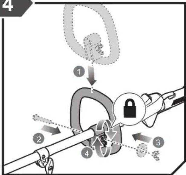
ATTACHING THE FRONT HANDLE
■ Loosen and remove the bolt and wing nut from the front handle.
■ Install the front handle onto the upper shaft.
■ Replace the bolt and wing nut and tighten the wing nut securely.
ATTACHING THE GRASS DEFLECTOR
■ Insert the tab on the mounting bracket in the slot on the grass deflector.
■ Insert the screw into the grass deflector.
■ Tighten the screw securely.
ATTACHING THE POWER HEAD TO THE TRIMMER ATTACHMENT
WARNING
Never attach or adjust any attachment while the power head is running. Failure to stop the engine may cause serious personal injury.
■ The trimmer attachment connects to the power head by means of a coupler device.
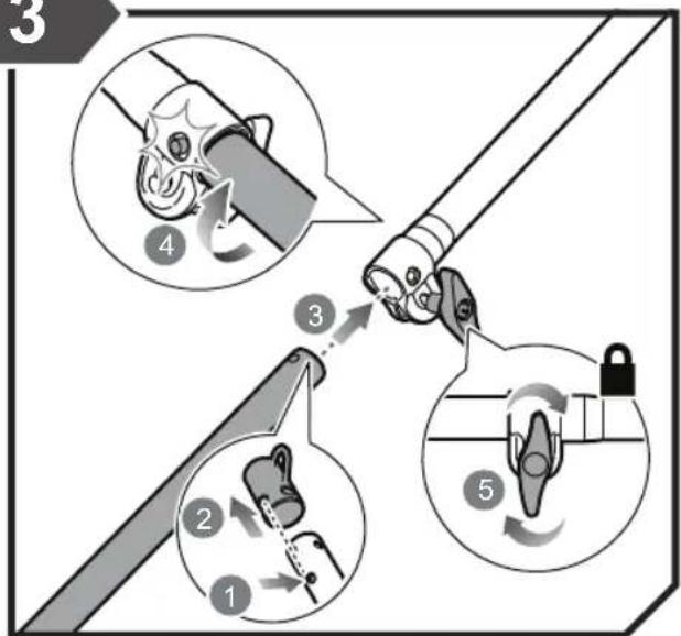
■ Loosen the knob on the coupler of the power head shaft and remove the end cap from the attachment.
■ Push in the button located on the attachment shaft.
■ Align the button with the guide recess on the power head coupler and slide the two shafts together.
■ Rotate the attachment shaft until the button locks into the positioning hole.
NOTE: If the button does not release completely in the positioning hole, the shafts are not locked into place. Slightly rotate from side to side until the button is locked into place.
■ Tighten the knob securely.
REMOVING THE ATTACHMENT FROM THE POWER HEAD
■ Loosen the knob.
■ Push in the button and twist the shafts to remove and separate the ends.
ATTACHING THE HARNESS
NOTE: Always use the harness with your trimmer.
■ Connect the latch on the strap to the strap hanger.
■ Adjust the strap to a comfortable position.
NOTE: To quickly release the product from the harness, sharply pull the quick release tab.
INSTALLING THE PRO CUT II HEAD TO THE GRASS TRIMMER
■ Stop the engine.
■ Remove the installed string head.
■ Install the drive shaft unto the lower boom. Turn clockwise for RLT254CDSO and counterclockwise for RLT254SDSO using the combination wrench.
■ Install the PRO CUT II string head on the drive shaft until fully seated.
■ Install the spool retainer. Turn clockwise for RLT254CDSO and counterclockwise for RLT254SDSO.
INSTALLING THE LINE IN THE PRO CUT II HEAD
NOTE: Use a monofilament line diameter 2.7 mm. Use original manufacturer's replacement line for best performance. 2.4 mm line is not compatible with the PRO CUT head. For the head to secure the line safely, 2.7 mm line must be used.
■ Stop the engine.
■ Gather two of the pre-cut lengths of trimmer line provided or cut two pieces of trimmer line (in 28 cm lengths).
■ Insert the line into the load slots located on the sides
of the line head. Line should be pushed in until approximately 2 cm protrudes from the holes on the top of the line head.
■ Once the line protrudes 2 cm from the holes on the top of the line head, gently pull back slightly to ensure the line is gripped properly.
OPERATION
FUEL AND REFUELING
HANDLING THE FUEL SAFELY
■ Always handle fuel with care, it is highly flammable.
■ Always refuel outdoors where there are no sparks and flames. Do not inhale fuel vapour. Do not smoke.
■ Do not let petrol or lubricant come in contact with your skin.
- Keep petrol and lubricant away from the eyes. If petrol or lubricant comes in contact with the eyes, wash them immediately with clean water. If irritation is still present, see a physician immediately.
■ Clean up spilled petrol immediately.
■ Always transport and store fuel in a container approved for petroleum.
MIXING THE FUEL
■ The product is powered by a 2-stroke engine and requires pre-mixing petrol and 2-stroke lubricant. Premix unleaded petrol and 2-stroke engine lubricant in a clean container approved for petrol.
■ The engine is certified to operate on unleaded petrol intended for motor vehicle use with an octane rating of 91 or higher.
- Do not use any type of pre-mixed petrol / lubricant from fuel service stations, this includes the pre-mixed petrol / lubricant intended for use in mopeds, motorcycles, etc.
■ Use synthetic 2-stroke lubricant only. Do not use automotive lubricant or 2-cycle outboard lubricant.
■ Mix 2% synthetic 2-stroke lubricant into the petrol. This is a 50:1 ratio.
■ Mix the fuel thoroughly and also each time before refueling.
■ Mix in small quantities. Do not mix quantities larger than usable in a 30-day period. A synthetic 2-stroke lubricant containing a fuel stabiliser is recommended.

1 l + 20 ml =
2 l + 40 ml =
3 l + 60 ml = 50:1
4 l + 80 ml =
5 l + 100 ml =
FILLING THE TANK
WARNING
Check for fuel leaks. If any are found, correct them before using the product to prevent fire or burn injury.
■ Clean surface around fuel cap to prevent contamination.
■ Loosen fuel cap slowly to release pressure and to keep fuel from escaping around the cap.
■ Carefully pour fuel mixture into the tank. Avoid spillage.
■ Prior to replacing the fuel cap, clean and inspect the gasket.
■ Immediately replace fuel cap and hand tighten. Wipe up any fuel spillage. Move 9 m away from refueling site before starting engine.
NOTE: It is normal for smoke to be emitted from a new engine during and after first use.
WARNING
Always shut off the engine before fuelling. Never add fuel to a machine with a running or hot engine. Move at least 9 m from refuelling site before starting the engine. Do not smoke!
STARTING AND STOPPING
WARNING
Never start or run the engine inside a closed or poorly ventilated area; breathing exhaust fumes can kill.
STARTING A COLD ENGINE:
NOTE: Lay the product on the ground. Ensure the cutting means will not contact anything when it starts to rotate.
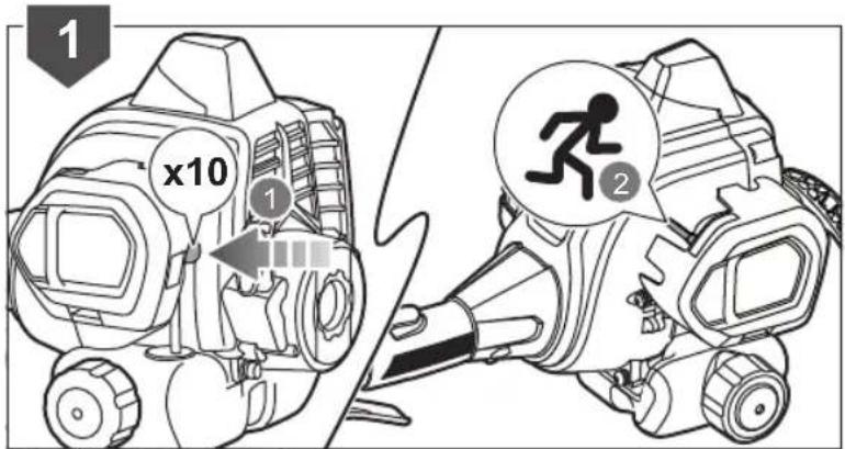
- Press the primer bulb 10 times.
NOTE: After the 7th press, the fuel should be visible in the primer bulb. If not, continue pressing until the fuel is visible. - Set the choke lever to choke position.
- Hold down the throttle lock and then squeeze the throttle trigger. Keep the throttle trigger squeezed completely following steps 3 to 7. Pull the starter grip until the engine attempts to start. Do not pull the starter grip more than 4 times.
- Set the choke lever to choke position.
- Pull the starter grip until the engine starts. Do not pull the starter grip more than 6 times.
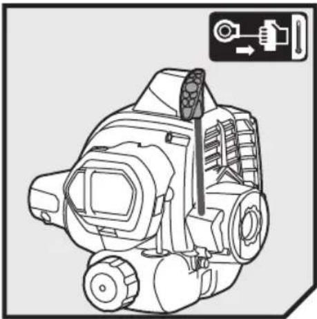
NOTE: If the engine does not start, repeat the procedure from step 2. - Allow the engine to run for 10 seconds.
- Set the choke lever to position.
STARTING A WARM ENGINE:
- Press the primer bulb 10 times.
- Set the choke lever to choke position.
- Hold down the throttle lock and then squeeze the throttle trigger completely and pull the starter grip until the engine starts. Do not pull the starter grip more than 6 times.
STARTING THE ENGINE USING AN ELECTRICAL STARTER (OPTIONAL):
WARNING
Only use the RYOBI OES18 electrical starter. Use of any other starter may damage the engine and cause serious personal injury.
WARNING
Before using the electrical starter to start the product, please read and understand completely the operation manual of the OES18 electrical starter to avoid improper operation and serious personal injury.
STARTING A COLD ENGINE BY ELECTRICAL STARTER:
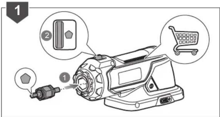
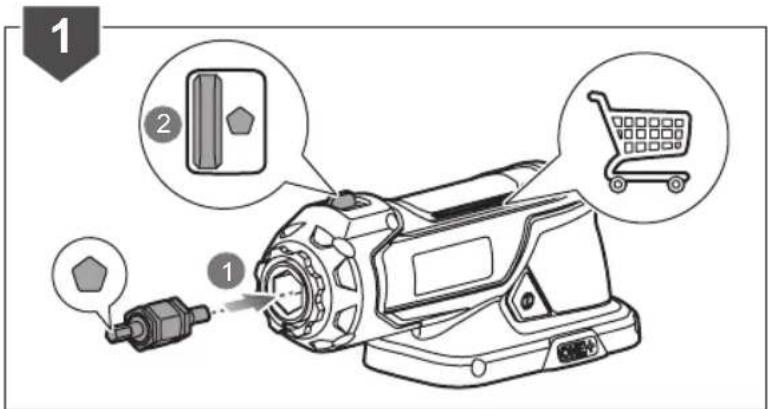
- Install the starter bit into the electrical starter with the pentagon bit facing outside.
- Push the F/R button to the left until the pentagon symbol shows on the F/R button.
- Lay the product on the ground and make sure that the cutting means do not come in contact with anything.
- Press the primer bulb 10 times.
NOTE: After the 7th press, the fuel should be visible in the primer bulb. If not, continue pressing until the fuel is visible.
- Set the choke lever to 1-doke position.
- Hold down the throttle lock and then squeeze the throttle trigger completely with your left hand and keep the throttle trigger squeezed completely through steps 6 to 12.
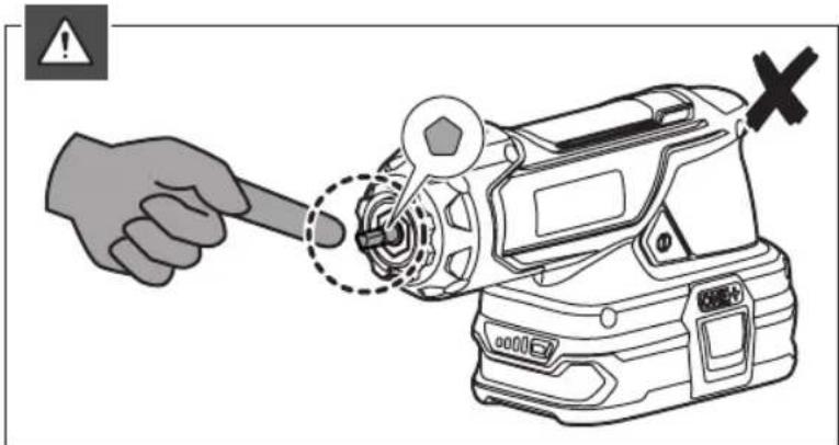
- Use your right hand to put the starter bit shaft to the shaft hole on the engine. Make sure the starter bit is properly engaged.
NOTE: The electrical starter is equipped with a safety interlock. Do not press and hold on the switch button when putting the electrical starter shaft into the shaft hole on the engine, otherwise the starter will not turn. The starter will not turn if the electrical starter is not properly engaged.
- Press and hold the electrical starter switch button until the engine attempts to start. Do not press the electrical starter for more than 4 seconds.
- Set the choke lever to I choke position.
- Press and hold the electrical starter switch button until the engine starts.
NOTE: If the engine does not start, repeat the procedure from step 5. Do not repeat the procedure more than 1 time. If the engine does not start after the second attempt, see the solution instruction for the "Flooded engine" in the "Troubleshooting" section of this manual.
- Allow the engine to warm up for 10 seconds.
- Set the choke level to choke position.
STARTING A WARM ENGINE BY ELECTRICAL STARTER:
- Install the starter bit into the electrical starter with the pentagon bit facing outside.
- Push the F/R button to the left until the pentagon
symbol shows on the F/R button.
-
Lay the product on the ground and make sure that the cutting means do not come in contact with anything.
-
Press the primer bulb 10 times.
-
Set the choke lever to position.
-
Hold down the throttle lock and then squeeze the throttle trigger completely with your left hand and keep the throttle trigger squeezed completely. Use the right hand to put the electrical starter shaft into the shaft hole on the engine. Make sure the starter is properly engaged.
-
Press and hold the electrical starter switch button until the engine starts.
NOTE: If the engine does not start, repeat the procedure from step 5. Do not repeat the procedure more than 1 time. If the engine does not start after the second attempt, see the solution instruction for the "Flooded engine" in the "Troubleshooting" section of this manual.
STOPPING THE ENGINE:
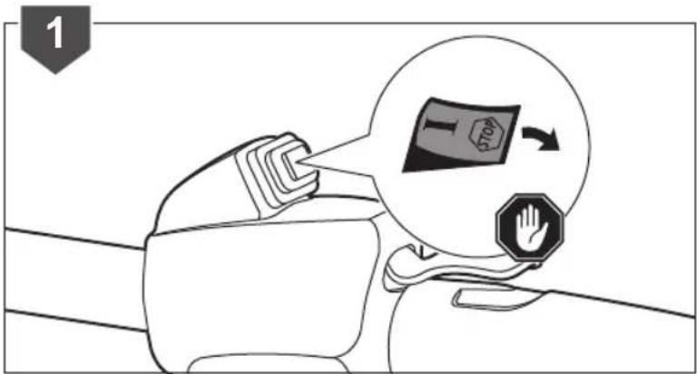
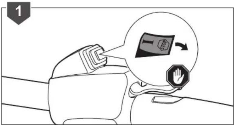
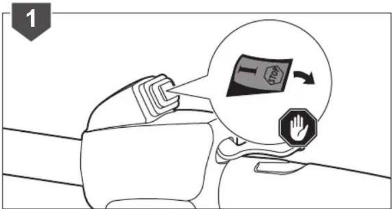
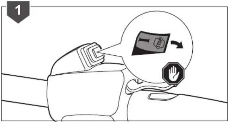
- Set the switch to the "STOP" (OFF) position.
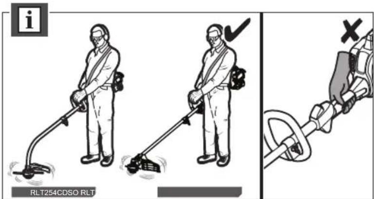
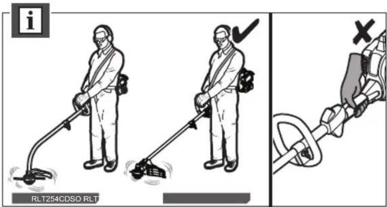
Hold the product with the right hand on the rear handle and the left hand on the front handle. Keep a firm grip with both hands while in operation. The product should be held at a comfortable position with the trigger handle about hip height.
Always operate the product at full throttle. Prolonged cutting at partial throttle will result in lubricant dripping from the silencer. Cut tall grass from the top down. This will prevent grass from wrapping around the shaft housing and bump head which may cause damage from overheating. If grass becomes wrapped around the bump head, stop the engine, and remove the grass.
CUTTING TIPS
■ Avoid hot surfaces by always keeping the product away from your body.
- Keep the product tilted toward the area being cut; this is the best cutting area.
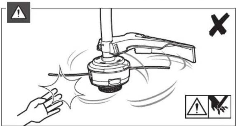
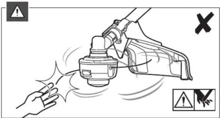
■ The product cuts when passing the product from right to left. This will avoid throwing debris at the operator. Avoid cutting in the dangerous area shown in illustration.
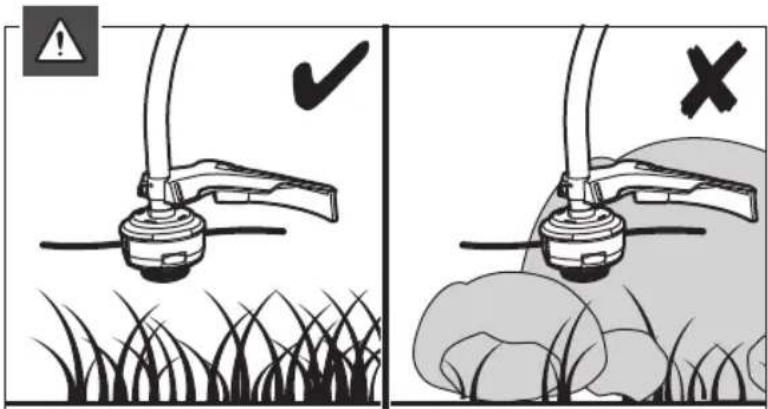
■ Use the tip of the string to do the cutting; do not force the string head into the uncut grass.
■ Wire and picket fences cause extra string wear, even breakage.
■ Stone and brick walls, kerbs, and wood may wear string rapidly.
- Avoid trees and shrubs. Tree bark, wood mouldings, cladding and fence posts can be easily damaged by the string.
ADVANCING THE LINE IN SPEED WINDER STRING HEAD
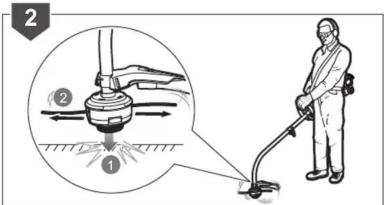
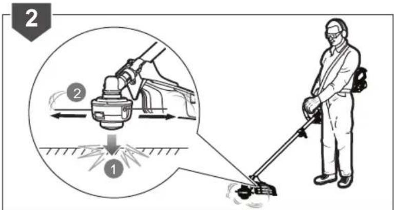
Line advance is controlled by tapping the string head on grass while running engine at full throttle.
■ Run engine at full throttle.
■ Tap the knob on ground to advance string. The string advances each time the head is tapped. Do not hold the
knob on the ground.
NOTE: The line trimming cut-off blade on the grass deflector will cut the line to the correct length.
NOTE: If the string is worn too short, you may not be able to advance the string by tapping it on the ground. If so, stop the engine, and manually advance the line.
ADVANCING THE CUTTING LINE MANUALLY
■ Stop the engine.
- Push the knob in while pulling on string(s) to manually advance the line.
REPLACING THE SPEED WINDER STRING HEAD (FOR RLT254CDSO ONLY)
■ Stop the engine.
■ Align the spanner along both flat side of arbor flange washer.
■ Turn the string head counterclockwise by hand to remove the old one.
- Replace a new string head, align the nut in the string head to the connector shaft of lower boom.
■ Turn the string head clockwise by hand to tighten, recommended torque is 6 N.M.
REPLACING THE SPEED WINDER STRING HEAD (FOR RLT254SDSO ONLY)
■ Stop the engine.
■ Place the combination wrench through the hole in the upper flange washer and the hole in the gear head.
■ Turn the string head clockwise by hand to remove.
- Replace a new string head, align the nut in string head to gear box shaft.
■ Turn the string head counterclockwise by hand to tighten, recommend torque is 6 N.M.
REPLACING THE LINE IN THE SPEED WINDER STRING HEAD
■ Ensure the product is in "off" position.
■ Use a 2.4 mm diameter monofilament string.
- Cut one piece of string approximately 5.4 m in length.
■ Rotate the bump knob clockwise as necessary to align the arrows on the bump knob with the arrows on the lower housing of string head.
■ Insert one end of the string into the eyelet located on the side of the string head and push until string comes out through eyelet on the other side.
■ Continue to push string through the string head until the middle section of the string is inside the string head and string outside the string head is evenly divided on each side.
■ Rotate the knob on the string head clockwise to wind the line.
■ Wind the string until approximately 20 cm remains protruding from the string head.
CLEANING THE EXHAUST PORT AND MUFFLER
Depending on the type of fuel used, the type and amount of lubricant used, and/or your operating conditions, the exhaust port and silencer may become blocked with carbon
deposits. If you notice a power loss with your gas powered product, a qualified service technician will need to remove these deposits to restore performance.
CLEANING THE SPARK ARRESTOR
The spark arrestor must be cleaned or replaced every 25 hours to ensure proper performance of your product. Spark arrestors may be in different locations depending on the model purchased.
CLEANING THE AIR FILTER
For proper performance and long life, keep the air filter clean.
■ Ensure the product is in "off" position.
■ Remove the air filter cover.
■ Remove the air filter and clean it with warm soapy water.
■ Rinse, and let the air filter dry completely.
■ Work two drops of lubricant into the air filter.
■ Replace the air filter (fits only one way).
■ Replace the air filter cover.
NOTE: The filter should be replaced annually for best performance.
FUEL CAP
WARNING
A leaking fuel cap is a fire hazard and must be replaced immediately.
The fuel cap contains a non-serviceable filter and a check valve. A clogged fuel filter will cause poor engine performance. If performance improves when the fuel cap is loosened, check valve may be faulty or filter clogged.
REPLACING THE SPARK PLUG
WARNING
The material of the spark plug is metal. It becomes very hot after you stop the engine. Wait for the engine to cool down before disassembling the metal spark plug boot to avoid personal injury.
NOTE: This engine uses a Champion RCJ6Y or equivalent with 0.63 mm (0.025 in.) electrode gap. Use an exact replacement and replace annually.
■ Stop the engine.
■ Hold the front portion of the rubber protect boot and pull it away from the housing.
■ Pull the rubber protect boot upward to release the hook.
■ Twist the metal spark plug boot and pull it away from the spark plug.
■ Loosen the spark plug by turning it counter clockwise with a wrench. Remove the old spark plug and replace with a new one. Assemble back the metal spark plug boot and the rubber protect boot.
ATTACHING THE HANGER CAP
To use the hanger cap, push in the button and place the hanger cap over the lower end of the attachment. Slightly rotate the cap from side to side until the button locks into place.
NOTE: The secondary hole in the attachment shaft can be used for hanging purposes as well.
RLT254CDSO




RLT254SDSO
natural_image
Technical line drawings of three mechanical components: a rod, a pressure pump, and a circular base (no text or symbols)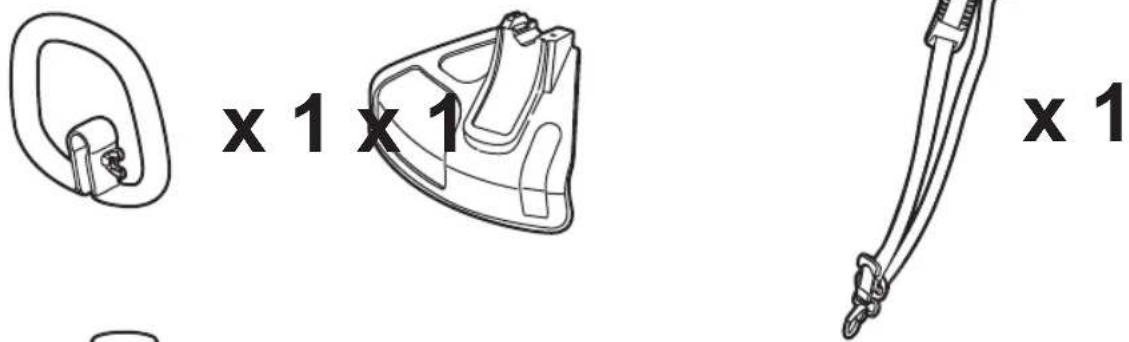



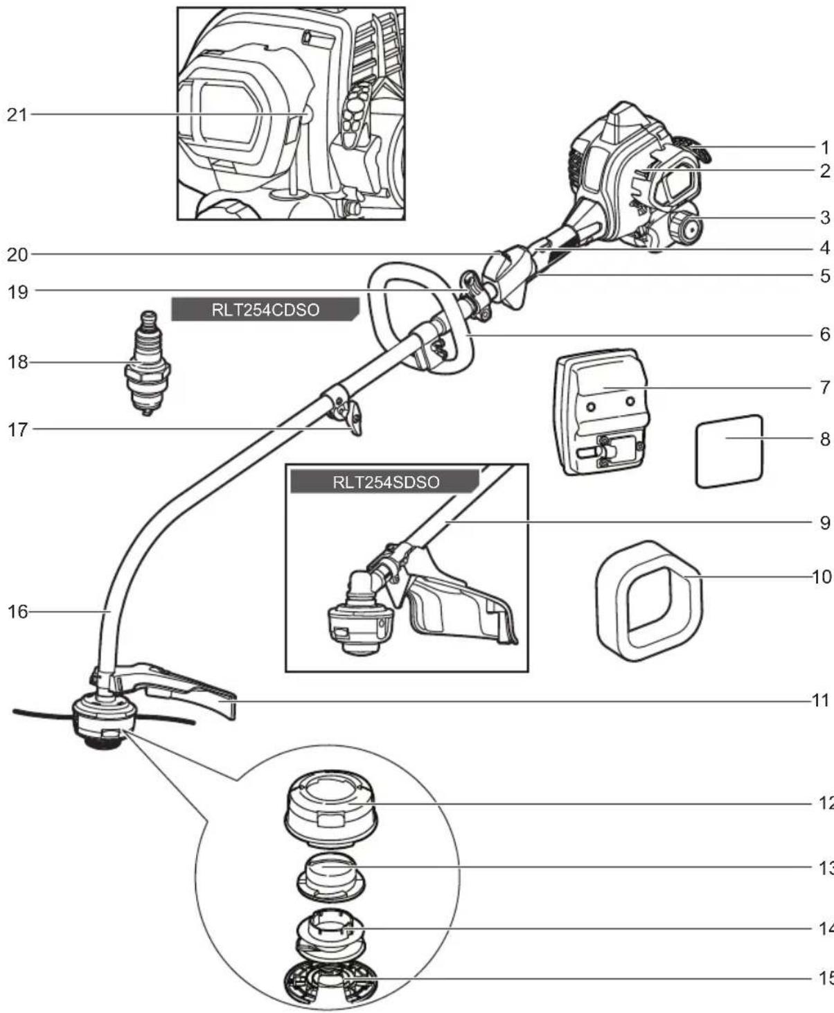
KNOW YOUR PRODUCT
- Starter grip
- Choke lever
- Fuel cap
- Throttle lock
- Throttle trigger
- Front handle
-
Muffler
-
Spark arrestor
- Straight shaft (RLT254SDSO)
- Air filter
- Grass deflector
- Lower housing
- Bump knob
-
Spool
-
Upper housing
- Curved shaft (RLT254CDSO)
- Knob
- Spark plug
- Hanger
- Switch
- Primer bulb
GETTING STARTED
1
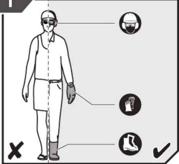
Always wear safety goggles or safety glasses with side shields when operating the product. Failure to do so could result in objects being thrown into your eyes resulting in possible serious injury. When handling the trimmer assembly, wear non-slip, heavy-duty protective gloves. Wear non-skid, protective footwear that will protect your feet and improve your footing on slippery surfaces.
2a
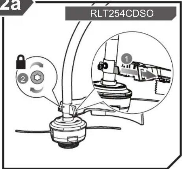
RLT254CDSO: Attach the grass deflector.
4
flowchart
graph TD
    A["Contact"] --> B{Check}
    B -->|1| C["Car"]
    B -->|2| D["Car with chain"]
    B -->|3| E["Car with gear"]
    B -->|4| F["Car with gear"]
    C --> G["Lock"]
    D --> H["Gear"]
    E --> I["Gear"]
Attach the D-handle. Attach the harness..
5

GETTING STARTED
2b

RLT254SDSO: Attach the grass deflector.
3
flowchart
graph TD
    A["Step 1: Cutting"] --> B["Step 2: Locking"]
    B --> C["Step 3: Locking"]
    C --> D["Step 4: Locking"]
    D --> E["Step 5: Locking"]
Attach the lower shaft.
6
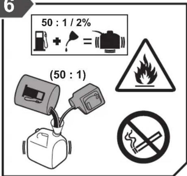
Use synthetic 2-stroke lubricant only. Do not use automotive lubricant or 2-stroke outboard lubricant. Mix 2% synthetic 2-stroke lubricant into the petrol. This is a 50:1 ratio.
7
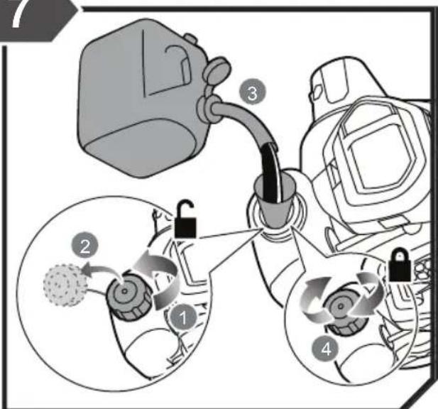
Remove the fuel cap and pour the fuel mixture into the tank. Avoid spillage. Immediately replace fuel cap and hand tighten.
OVERVIEW
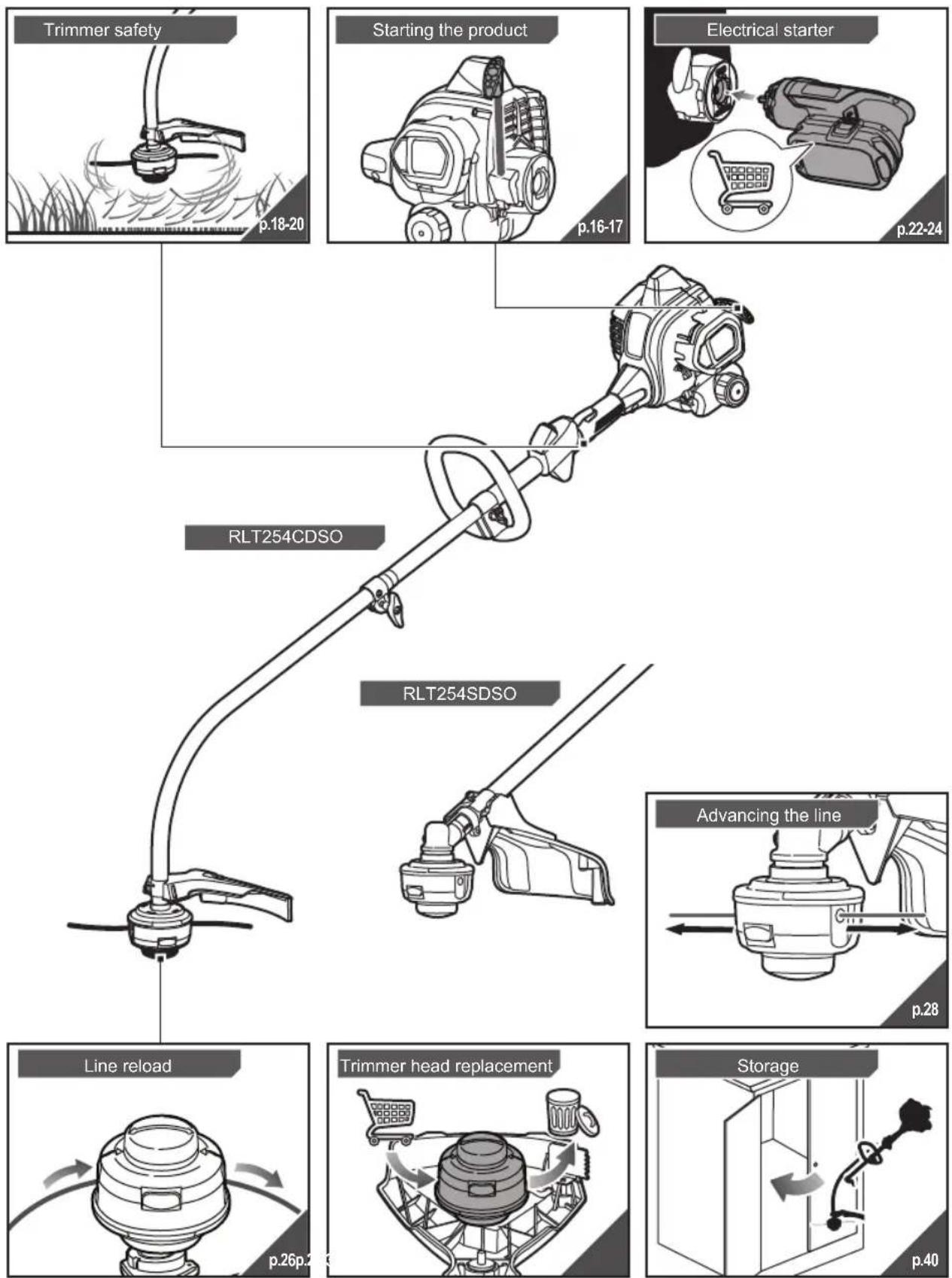
flowchart
graph TD
    A["Trimmer safety"] --> B["p.18-20"]
    C["Starting the product"] --> D["p.16-17"]
    E["Electrical starter"] --> F["p.22-24"]
    G["RLT254CDSO"] --> H["RLT254SDSO"]
    I["Line reload"] --> J["p.26p.2"]
    K["Trimmer head replacement"] --> L["Storage"]
    M["Advancing the line"] --> N["p.28"]
OVERVIEW


OPERATION
natural_image
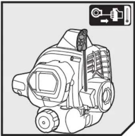
Technical line drawing of a mechanical device with no visible text or symbolsSTARTING A COLD ENGINE
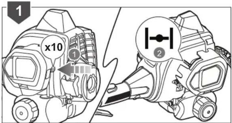
- Press the primer bulb 10 times. Set the choke lever to "Full" position.
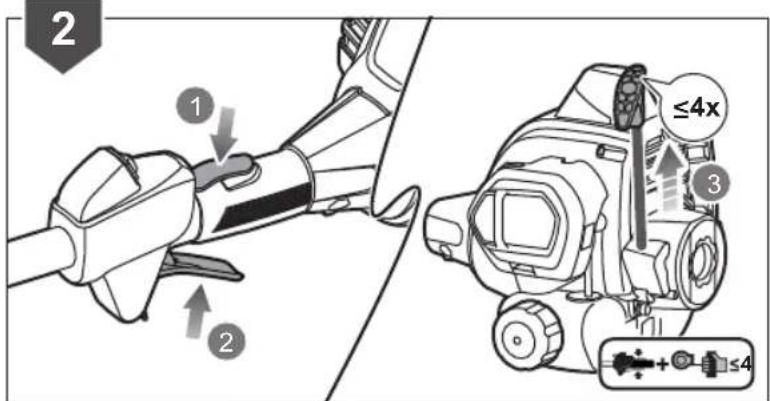
- Keep the throttle trigger squeezed completely through steps 2 to 4 and pull the starter grip until the engine attempts to start. Do not pull the starter grip more than 4 times.
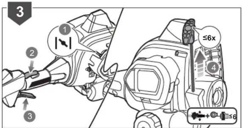
- Set the choke lever to "half" position. Pull the starter grip until the engine starts. Do not pull the starter grip more than 6 times.
- Allow the engine to run for 10 seconds. Set the choke lever to "Run" position.

OPERATION
natural_image
Technical line drawing of a mechanical device with no visible text or symbolsSTARTING A WARM ENGINE
- Press the primer bulb 10 times. Set the choke lever to position.
- Squeeze the throttle trigger. Pull the starter grip until the engine starts. Do not pull the starter grip for more than 6 times.

OPERATION

natural_image
Illustration of a sprinkler spraying water over grass (no text or symbols)RLT254CDSO:
NOTE: Hold the product with the right hand on the trigger handle and the left hand on the left handle.
WARNING: Do not cut in a dangerous cutting area. Avoid trees and shrubs. Tree bark, wood mouldings, cladding, and fence posts can easily be damaged by the line.
WARNING Exercise extreme caution when using the product.
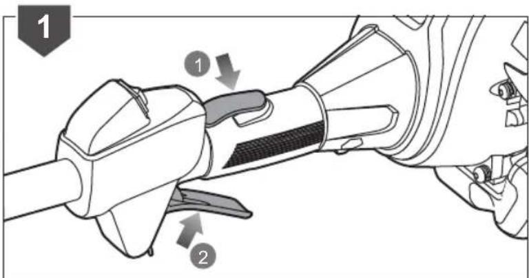
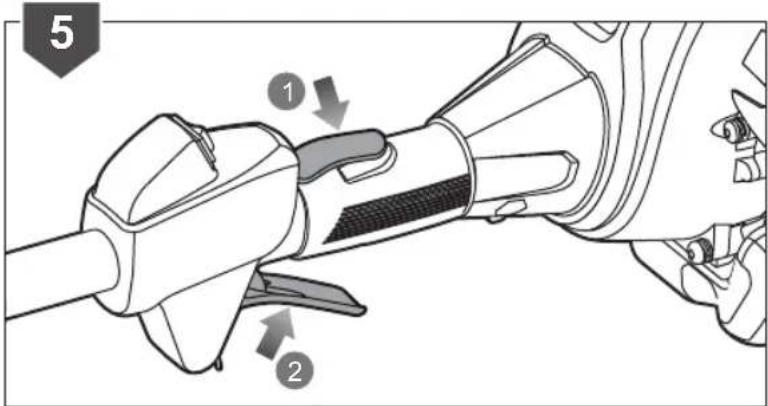
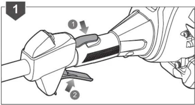
- To start operating the product, hold down the throttle lock (1) and then squeeze the throttle trigger (2).
OPERATION
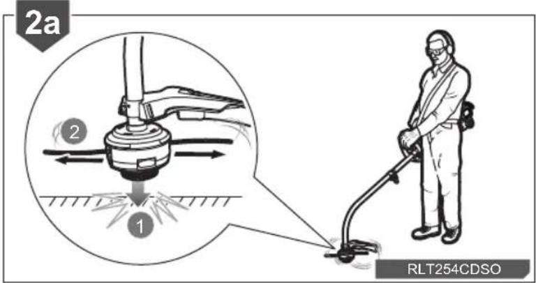
- Tap the knob on the ground to advance the line. The line advances each time the head is tapped. Do not hold the knob on the ground.
NOTE: The line trimming cut-off blade on the grass deflector will cut the line to the correct length.
NOTE: The small blade fitted to the cutting attachment guard is designed to trim the new extended line to the correct length for safe and optimum performance. It is very sharp; do not touch it, particularly when cleaning the product.
NOTE: Cut tall grass from the top down. This will prevent grass from wrapping around the shaft housing and bump head, which may cause damage from overheating.
NOTE: For cutting ease and safety, cut the grass from the right side to the left side.
natural_image
Mechanical assembly diagram showing a motor and gear assembly with motion arrows, no text or symbols present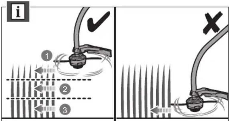

OPERATION

natural_image
Illustration of a manual sprinkler spraying water over grass (no text or symbols)RLT254SDSO:
NOTE: Hold the product with the right hand on the trigger handle and the left hand on the left handle.
WARNING: Do not cut in a dangerous cutting area. Avoid trees and shrubs. Tree bark, wood mouldings, cladding, and fence posts can easily be damaged by the line.
WARNING: Exercise extreme caution when using the product.
- To start operating the product, hold down the throttle lock (1) and then squeeze the throttle trigger (2).

OPERATION
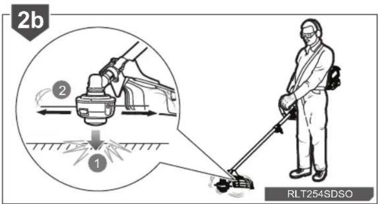
- Tap the knob on the ground to advance the line. The line advances each time the head is tapped. Do not hold the knob on the ground.
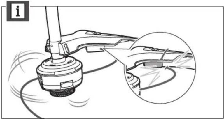
NOTE: The line trimming cut-off blade on the grass deflector will cut the line to the correct length.
NOTE: The small blade fitted to the cutting attachment guard is designed to trim the new extended line to the correct length for safe and optimum performance. It is very sharp; do not touch it, particularly when cleaning the product.
NOTE: Cut tall grass from the top down. This will prevent grass from wrapping around the shaft housing and bump head, which may cause damage from overheating.
NOTE: For cutting ease and safety, cut the grass from the right side to the left side.

natural_image
Technical illustration of a spray gun with a magnified inset showing the tool tip (no text or symbols present)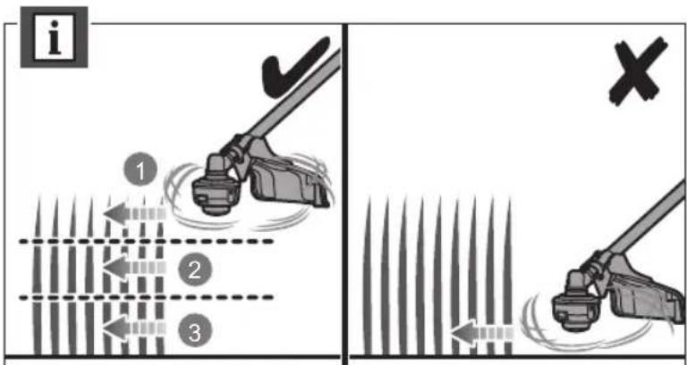

OPERATION
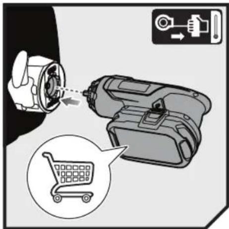
STARTING A COLD ENGINE BY ELECTRICAL STARTER
- Install the starter bit into the electrical starter with the pentagon bit facing outside. Push the F/R button to the left until the pentagon symbol shows on the F/R button.
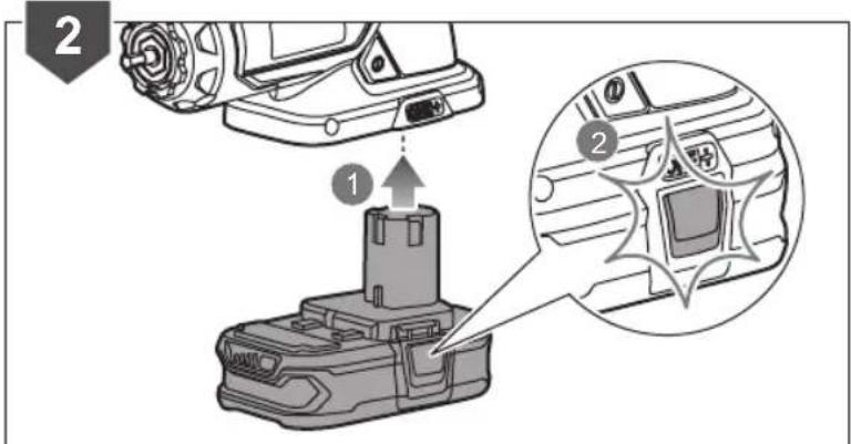
- Insert the battery pack into the electrical starter until it clicks into place.
WARNING: Keep your hands away from the starter bit to avoid injury.
- Lay the product on the ground, press the primer bulb 10 times, and then set to choke position.
NOTE: The fuel should be visible in the primer bulb after the 7th press.

natural_image
Illustration of a hand using a wrench to adjust a mechanical component, with no visible text or symbols.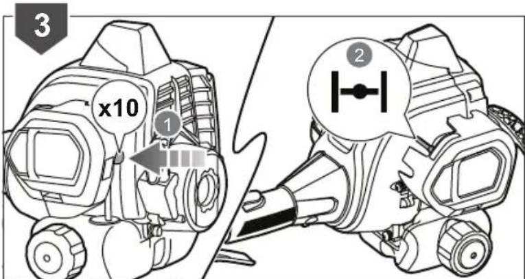
OPERATION
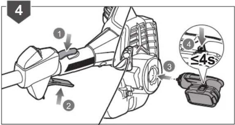
- Hold down the throttle lock and squeeze the throttle trigger (through step 6). Put the starter bit shaft to the shaft hole on the engine.
Press and hold the electrical starter switch button until the engine attempts to start. Do not press the electrical starter for more than 4 seconds.
- Set to choke position. Press and hold the electrical starter switch button until the engine starts.
NOTE: If the engine does not start, repeat the procedure again from step 3
-
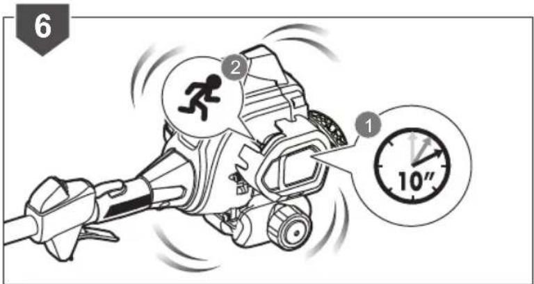
Allow the engine to run for 10 seconds, and then set the lever to position.
-
Hold down the throttle lock and then squeeze the throttle trigger to start using the product.


OPERATION

STARTING A WARM ENGINE BY ELECTRICAL STARTER
- Install the starter bit into the electrical starter with the pentagon bit facing outside. Push the F/R button to the left until the pentagon symbol shows on the F/R button.
- Insert the battery pack into the electrical starter until it clicks into place.
WARNING Keep your hands away from the starter bit to avoid injury.
- Lay the product on the ground and make sure that the cutting means does not come in contact with anything. Press the primer bulb 10 times and then set the choke lever to position.


OPERATION
- Hold down the throttle lock and squeeze the throttle trigger. Put the starter bit shaft into the shaft hole on the engine. Press and hold the electrical starter switch button until the engine starts.
NOTE: If the engine does not start, repeat the procedure from step 3. Do not repeat the procedure more than 1 time.
- Hold down the throttle lock and then squeeze the throttle trigger to start using the product.

OPERATION
natural_image
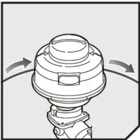
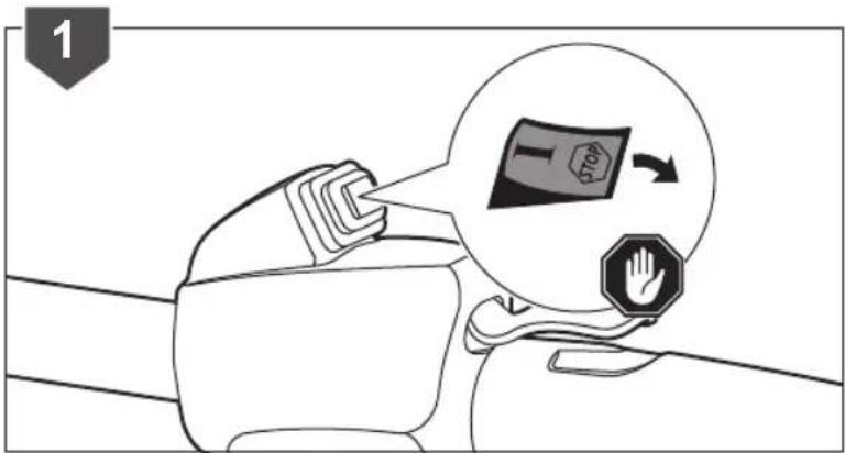
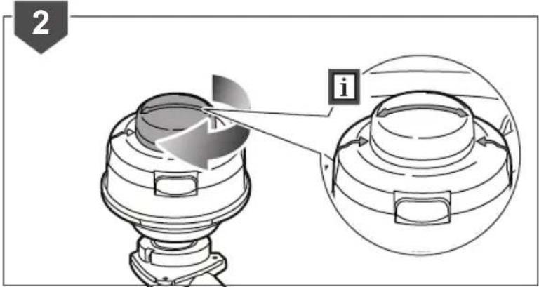
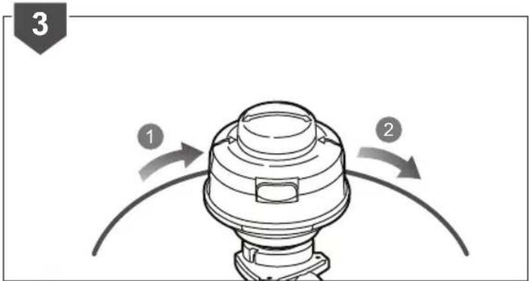
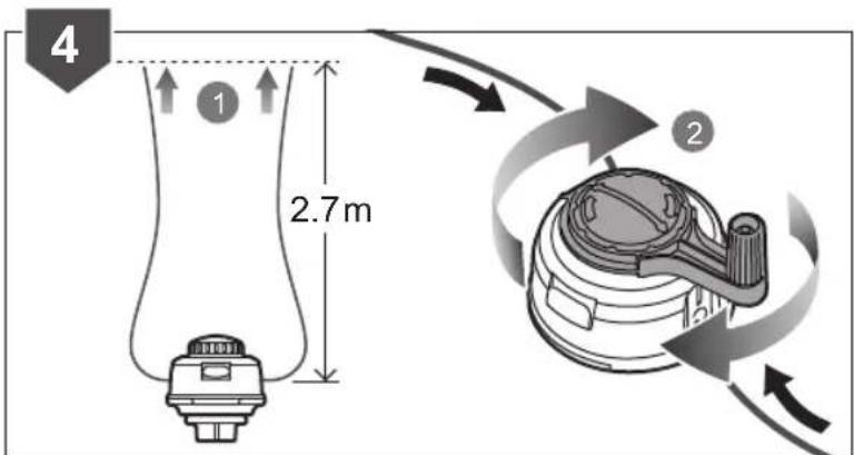
Diagram of a mechanical component with curved arrows indicating rotation or movement (no text or symbols)REPLACING THE LINE
- Turn off the product
- Rotate the bump knob on the trimmer head until the line on the centre of the bump knob aligns with arrows on top of trimmer head.
- Use a 2.4 mm diameter monofilament string. Cut one piece of string approximately 5.4 m in length. Insert one end of the line located on the side of the trimmer head and push until line comes out through the eyelet on the other side. Continue to push string through the string head until the middle section of the string is inside the string head.
- Ensure there is equal lengths of line on either side of the trimmer head (max. 2.7 m per side). Rotate the locking knob with speed winder on the trimmer head to wind the line.
OPERATION
- Wind the line until approximately 20 cm remains protruding from the trimmer head.
i


OPERATION
natural_image
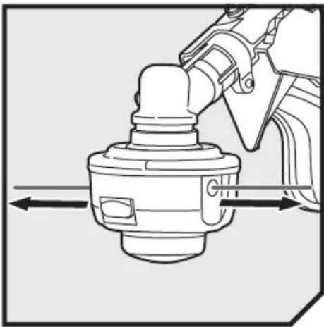
Mechanical assembly diagram showing a valve or connector with directional arrows indicating movement (no text or symbols present)ADVANCING THE LINE
- Run engine at full throttle.
- Tap the knob on ground to advance string. The string advances each time the head is tapped. Do not hold the knob on the ground.
NOTE: The line trimming cut-off blade on the grass deflector will cut the line to the correct length.

natural_image
Mechanical assembly diagram showing a rotating component with a magnified inset highlighting internal components (no text or symbols)OPERATION
natural_image
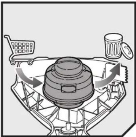
Diagram of a food storage or recycling system with a cart, trash bin, and cup (no text or symbols)RLT254CDSO: REPLACING THE STRING HEAD
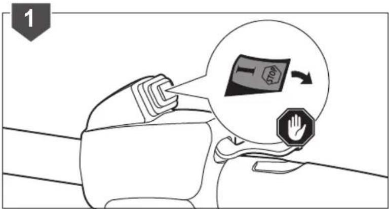
- Turn off the product
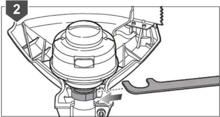
- Align the spanner along the flat side of arbor flange washer.
- Turn counterclockwise to remove the old string head.
- Install the new string head, align the nut in the string head to the connector shaft or lower boom and turn the string head clockwise by hand to tighten.
natural_image
Technical diagram of a mechanical assembly with a wrench inserted, showing internal components and no visible text or symbols.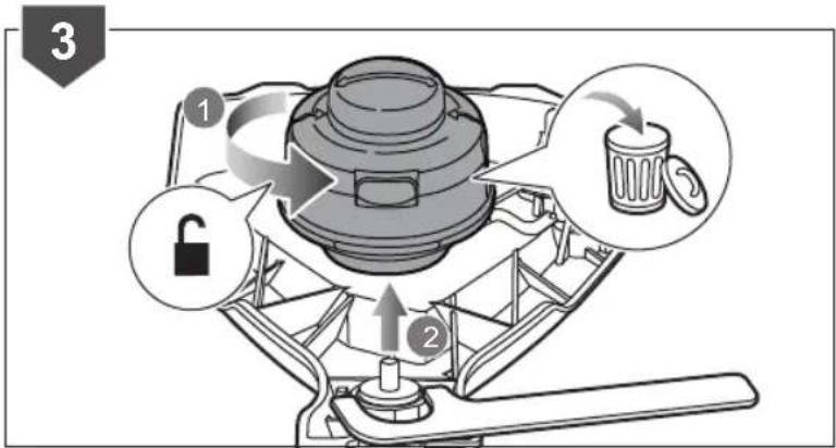

flowchart
graph TD
    A["Shopping Cart"] --> B["Lock"]
    B --> C["Lock"]
    C --> D["Lock"]
    D --> E["Lock"]
    E --> F["Lock"]
    F --> G["Lock"]
    G --> H["Lock"]
    H --> I["Lock"]
    I --> J["Lock"]
    J --> K["Lock"]
    K --> L["Lock"]
    L --> M["Lock"]
    M --> N["Lock"]
    N --> O["Lock"]
    O --> P["Lock"]
    P --> Q["Lock"]
    Q --> R["Lock"]
    R --> S["Lock"]
    S --> T["Lock"]
    T --> U["Lock"]
    U --> V["Lock"]
    V --> W["Lock"]
    W --> X["Lock"]
    X --> Y["Lock"]
    Y --> Z["Lock"]
    Z --> AA["Lock"]
    AA --> AB["Lock"]
    AB --> AC["Lock"]
    AC --> AD["Lock"]
    AD --> AE["Lock"]
    AE --> AF["Lock"]
    AF --> AG["Lock"]
    AG --> AH["Lock"]
    AH --> AI["Lock"]
    AI --> AJ["Lock"]
    AJ --> AK["Lock"]
    AK --> AL["Lock"]
    AL --> AM["Lock"]
    AM --> AN["Lock"]
    AN --> AO["Lock"]
    AO --> AP["Lock"]
    AP --> AQ["Lock"]
    AQ --> AR["Lock"]
    AR --> AS["Lock"]
    AS --> AT["Lock"]
    AT --> AU["Lock"]
    AU --> AV["Lock"]
    AV --> AW["Lock"]
    AW --> AX["Lock"]
    AX --> AY["Lock"]
    AY --> AZ["Lock"]
    AZ --> BA["Lock"]
    BA --> BB["Lock"]
    BB --> BC["Lock"]
    BC --> BD["Lock"]
    BD --> BE["Lock"]
    BE --> BF["Lock"]
    BF --> BG["Lock"]
    BG --> BH["Lock"]
    BH --> BI["Lock"]
    BI --> BJ["Lock"]
    BJ --> BK["Lock"]
    BK --> BL["Lock"]
    BL --> BM["Lock"]
    BM --> BN["Lock"]
    BN --> BO["Lock"]
    BO --> BP["Lock"]
    BP --> BQ["Lock"]
    BQ --> BR["Lock"]
    BR --> BS["Lock"]
    BS --> BT["Lock"]
    BT --> BU["Lock"]
    BU --> BV["Lock"]
    BV --> BW["Lock"]
OPERATION

flowchart
graph TD
    A["Shopping Cart"] --> B["Recycle Bin"]
    B --> C["Recycle Bin"]
    C --> D["Recycle Bin"]
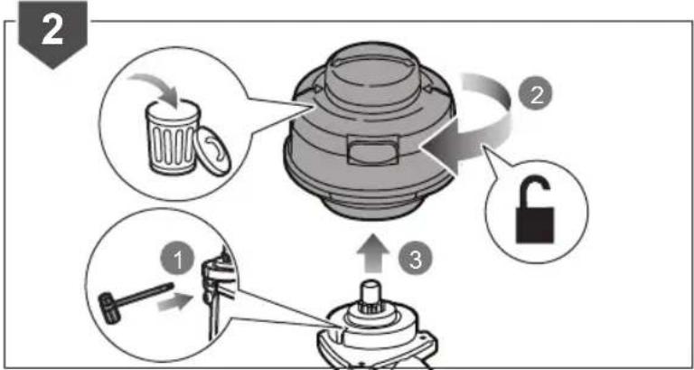
RLT254SDSO: REPLACING THE STRING HEAD
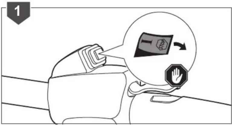
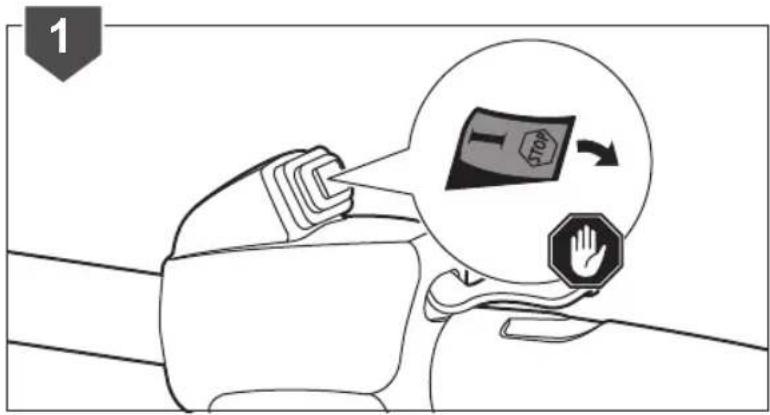
- Turn off the product
- Insert the combination wrench and then turn counterclockwise to remove the old string head.
- Install the new string head, align the nut in the string head to the connector shaft or lower boom and turn the string head counterclockwise by hand to tighten.
flowchart
graph TD
    A["Garbage Discharge"] --> B["Recycling Toilet"]
    B --> C["Locking"]
    C --> D["Fixing"]
    D --> E["Cleaning with Hammer"]

flowchart
graph TD
    A["Lock"] --> B["Switch"]
    C["Shopping Cart"] --> D["Doorbell"]
    E["Hand Tools"] --> F["Switch"]
    G["Switch"] --> H["Doorbell"]
OPERATION
natural_image
Technical line drawing of a mechanical component with no visible text or symbolsRLT254CDSO: INSTALLING THE PRO CUT II HEAD
- Turn off the product
- Install the drive shaft unto the lower boom. Turn clockwise using the combination wrench. Install the PRO CUT II string head on the drive shaft until fully seated.
- Turn clockwise to install the spool retainer.


OPERATION
natural_image
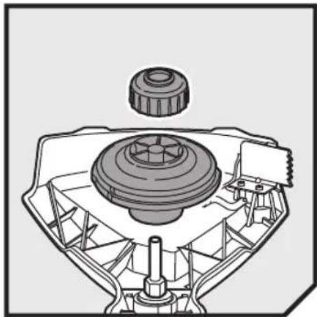
Mechanical assembly diagram showing a gear and shaft component (no text or labels)RLT254SDSO: INSTALLING THE PRO CUT II HEAD
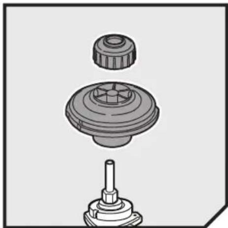
- Turn off the product.
- Install the drive shaft to the lower boom. Turn counterclockwise using the combination wrench. Install the PRO CUT II string head on the drive shaft until fully seated.
- Turn counterclockwise to install the spool retainer.

flowchart
graph TD
    A["Step 1: Lock mechanism"] --> B["Step 2: Inserted component"]
    B --> C["Step 3: Pulling lock mechanism"]
    C --> D["Step 4: Screw assembly with keyway"]
    style A fill:#f9f,stroke:#333
    style D fill:#bbf,stroke:#333

flowchart
graph TD
    A["Step 1: Lock"] --> B["Step 2: Arrow to lock"]
    B --> C["Step 3: Insert switch"]
    C --> D["Final mechanical component"]
OPERATION
natural_image
Diagram of a mechanical component with directional arrows indicating motion or force (no text or symbols)INSTALLING THE LINE IN THE PRO CUT II HEAD
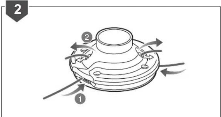
NOTE: Use a monofilament line diameter 2.7 mm.
- Turn off the product.
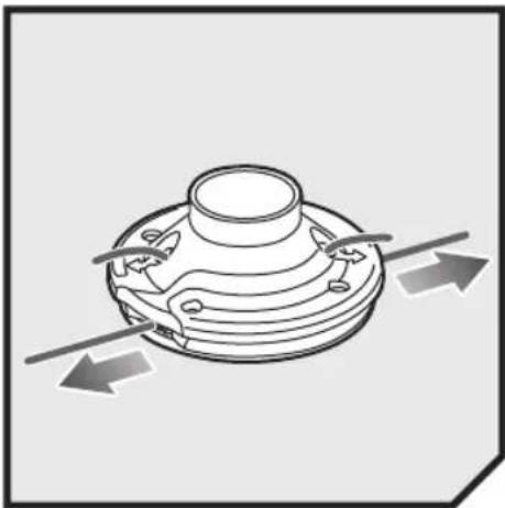
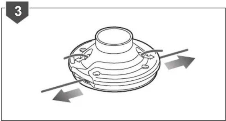
- Gather two of the pre-cut lengths of trimmer line provided or cut two pieces of trimmer line (in 28 cm lengths). Insert the line into the load slots located on the sides of the line head. Line should be pushed until approximately 2 cm protrudes from the holes on the top of the line head.
- Once the line protrudes 2 cm from the holes on the top of the line head, gently pull back slightly to ensure the line is gripped properly.
natural_image
Technical diagram of a mechanical component with directional arrows indicating motion or flow (no text or symbols)OPERATION
natural_image
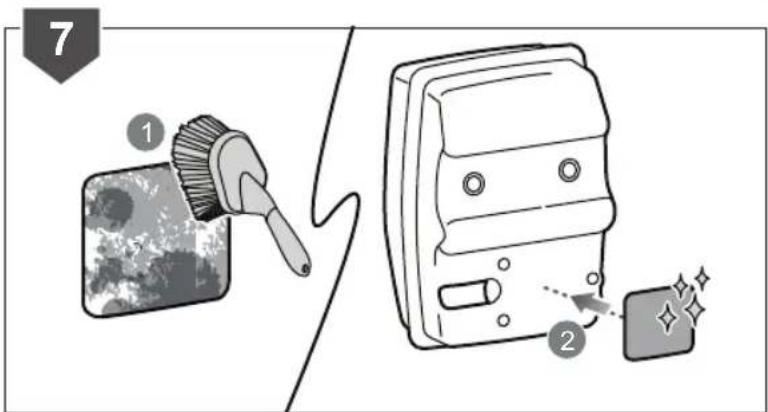
Illustration of a cleaning brush applying paint to a digital screen, with sparkles indicating texture and brightness (no text or symbols)CLEANING THE SPARK ARRESTOR
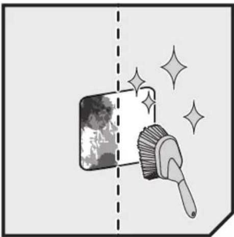
- Turn off the product.
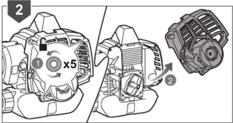
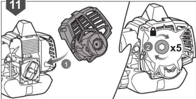
- Remove the rear housing of the powerhead to access the muffler.
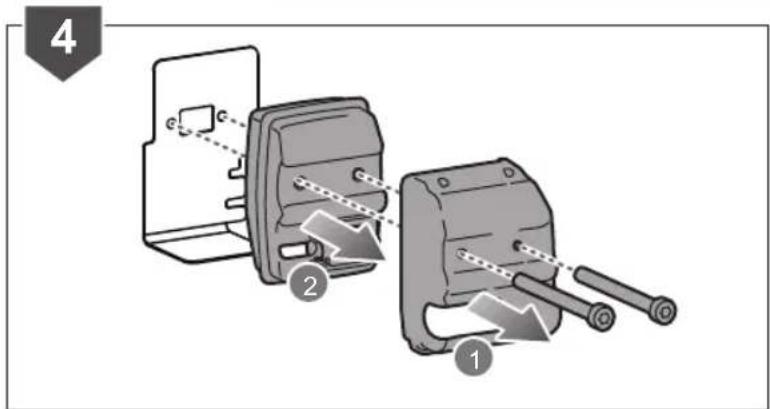
- Loosen the screws from the cylinder.
- Remove the muffler from the muffler shield.

OPERATION
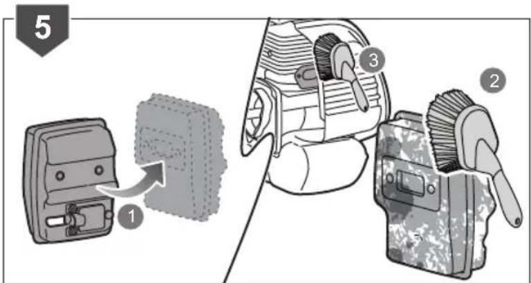
- Use the brush to clean the exhaust hole of the cylinder and intake hole of the muffler.
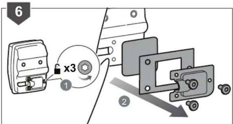
- Loosen the screws securing the spark arrestor, and then detach it from the muffler.
- Clean the spark arrestor with a small wire brush.
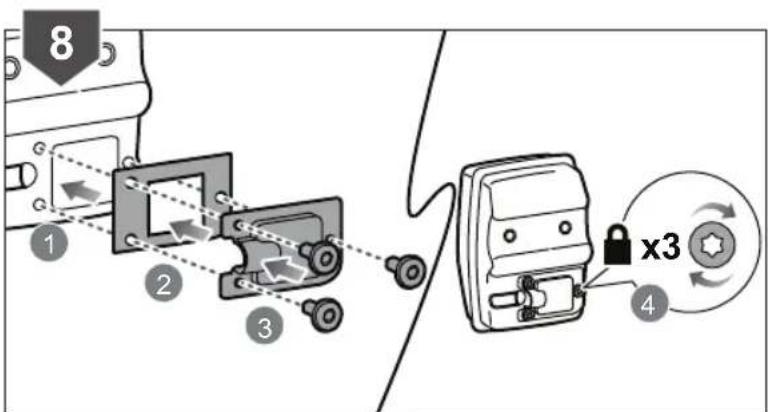
- After cleaning, install the spark arrestor back to the muffler. Attach the stamping plate and outlet tube to the muffler cover and then
flowchart
graph TD
    A["Step 1: Internal component"] --> B["Step 2: Internal device"]
    B --> C["Step 3: Wheelchair"]
    C --> D["Step 4: Lock mechanism with x3 label"]
    style A fill:#f9f,stroke:#333
    style D fill:#ccf,stroke:#333
OPERATION
tighten the three recess screws.
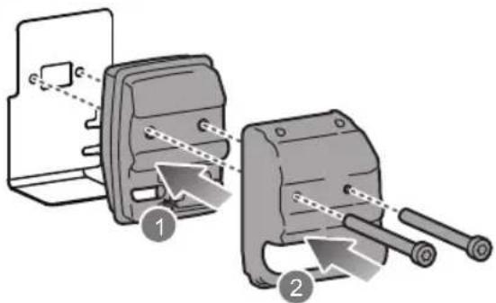
- Install the muffler back to the muffler shield.
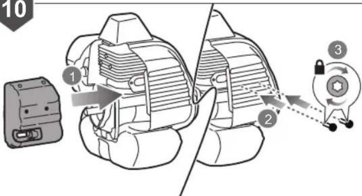
- Insert the muffler back to rear part of the powerhead, and then tighten the screws to secure.
- Place the rear housing and secure it with the five screws.
9
10
11
OPERATION

flowchart
graph TD
    A["Shopping Cart"] --> B["Recycle Bin"]
    B --> C["Recycle Bin"]
    C --> D["Recycle Bin"]
REPLACING THE SPARK PLUG
- Turn off the product
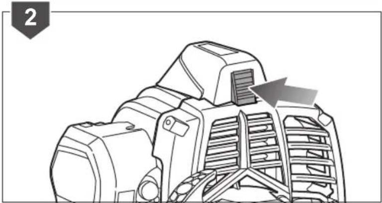
- Press the snap of protect cap
- Pull away the protect cap from the housing.
Twist the metal spark plug boot and pull it away from the spark plug.
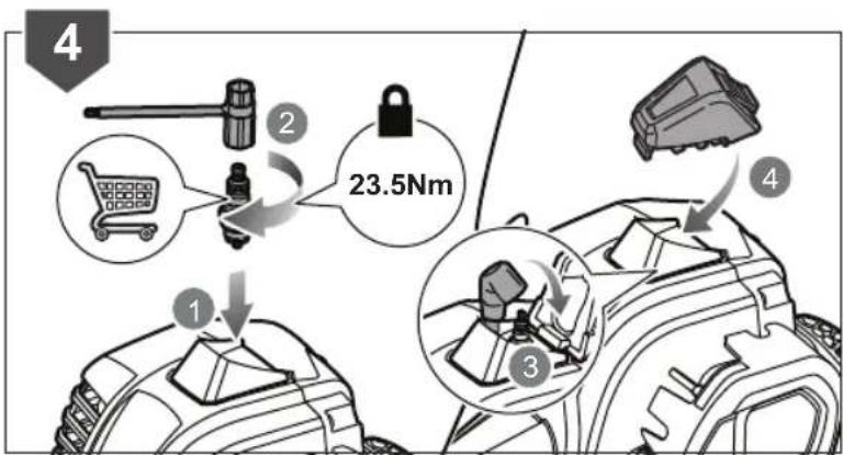
Loosen the spark plug by turning it in a counterclockwise direction using a combination wrench.
Remove the old spark plug and replace with a new one.
- Tighten by turning it in a clockwise direction or one half of a turn from finger tight using a combination wrench.
Assemble back the metal spark plug boot and the plastic protect cap.

natural_image
Technical line drawing of a mechanical component with no visible text or symbols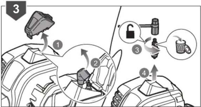
OPERATION
natural_image
Diagram showing mechanical components and a gear mechanism (no text or symbols)CLEANING THE FILTER
- Turn off the product.
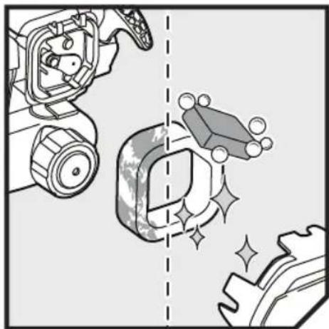
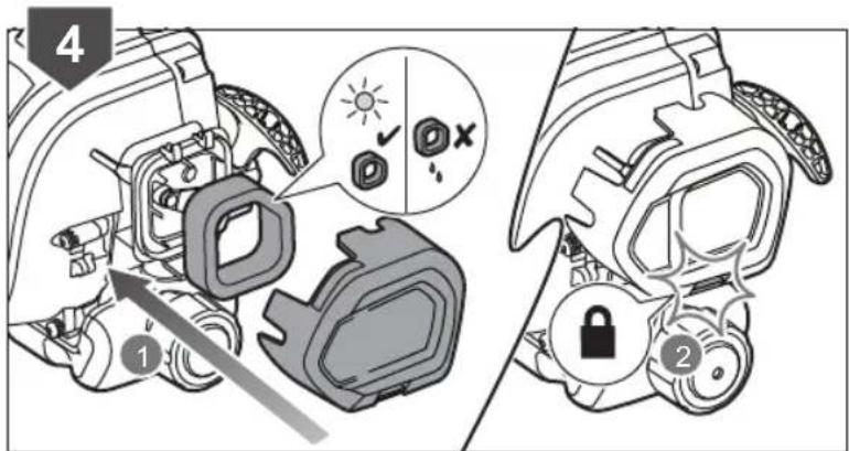
- Remove the air filter cover and the air filter.
- Clean the air filter with warm, soapy water.
- Rinse and dry the air filter completely.



MAINTENANCE
natural_image
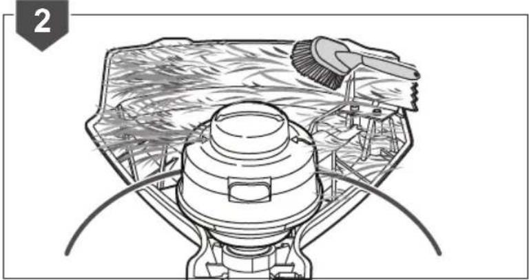
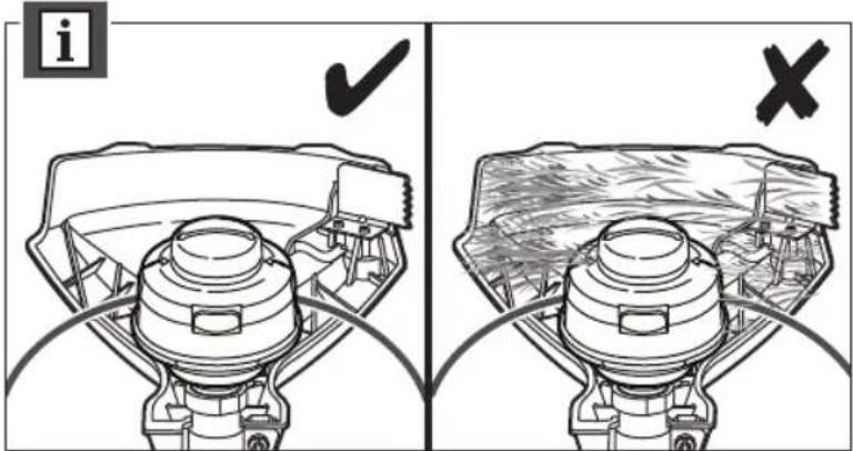
Illustration of a gas stove interior with decorative sparkles and a brush (no text or symbols)CLEANING THE PRODUCT
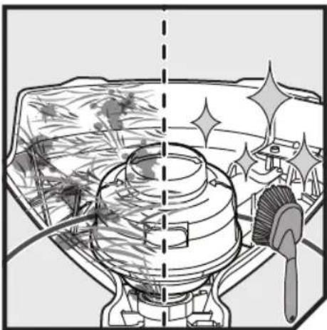
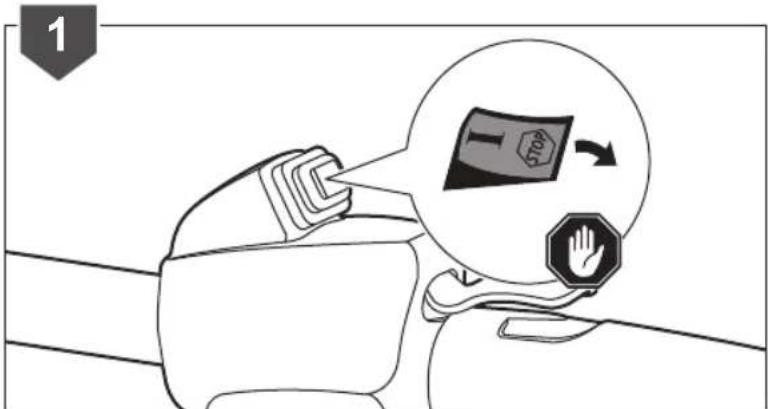
- Turn off the product, and allow it to cool down before cleaning.
- Clean all foreign material from the product.
WARNING: Keep away from corrosive agents such as garden chemicals and deicing salts.
WARNING: The small blade fitted to the cutting attachment guard is designed to trim the new extended line to the correct length for safe and optimum performance. It is very sharp; do not touch it, particularly when cleaning the product.
natural_image
Technical line drawing of a mechanical device with a brush and housing (no text or symbols)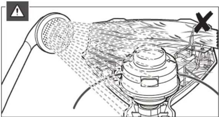
natural_image
Technical diagram of a mechanical device with spray nozzle and internal components, showing no readable text or symbols.
STORAGE

natural_image
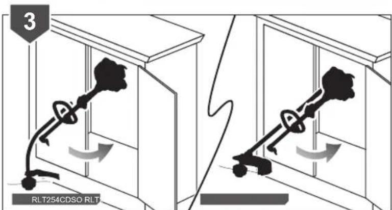
Illustration of a key inserted into a cabinet with an arrow indicating direction (no text or symbols)STORING THE PRODUCT
NOTE: Make sure to clean the product before storing.
- Turn off the product, and allow it to cool down before storing the product.
- Remove the upper shaft from the handle.
NOTE: If a cutting blade is fitted, cover it with the blade protector.
- Store the product.

flowchart
graph TD
    A["1: Lock"] --> B["2: Capture"]
    B --> C["3: Pulling part"]
    C --> D["4: Capture with key"]
    D --> E["End"]
TROUBLESHOOTING
IF THESE SOLUTIONS DO NOT SOLVE THE PROBLEM, CONTACT AN AUTHORISED SERVICE CENTRE.
| PROBLEM POSSIBLE CAUSE SOLUTION | ||
| Engine will not start No spark The spark plug may be damaged. Remove it and check for dirt and cracks. Replace with a new spark plug. | ||


| Bump knob hard to turn. | Screw threads dirty or damage. | Clean threads and lubricate with grease - if no improvement, replace bump knob. |
| Lubricant drips from muffler. Operating the product at part throttle. | Operate the product at full throttle. | |
| Use fresh fuel and correct synthetic 2-stroke lubricant mix.. | ||
PRODUCT SPECIFICATION
| Grass Trimmer | ||
| Model RLT254CDSO | RLT254SDSO | |
| Weight | ||
| - Without fuel, cutting attachment and harness | 4.94 kg 5.15 | kg |
| - Without fuel and harness, with trimmer head | 5.40 kg 5.70 | kg |
| Fuel tank volume 580 cm | ||
| Cutting swath 420 mm 457 mm | ||
| Engine displacement | 25.4 cm3 / cc | |
| Line diameter for SPEED WINDER string head | 2.4 mm | |
| Line diameter for PRO CUT II string head | 2.7 mm | |
| Maximum engine performance (in accordance with ISO 8893) | 0.75 kW | |
| Maximum rotational frequency of the spindle | 12,000 min-1 | 10,000 min-1 |
| Engine speed (rotational frequency) at idle | 2,600-3,400 min-1 | |
| Fuel consumption (in accordance with ISO 8893) at max. engine performance | 0.38 kg/h | |
| Specific fuel consumption (in accordance with ISO 8893) at max. engine performance | 0.5 kg/h | |
| Vibration (in accordance with ISO 22867): PRO CUT II/ SPEED WINDER string head) | ||
| Front handle | ||
| - Idling 5.3/5.9 m/s | 2 | 3.4/3.8 m/s2 |
| - Racing 10.1/6.1 m/s | 2 | 6.0/13.8 m/s |
| - Equivalent vibration total value | 8.0/6.0 m/s2 | 4.8/10.1 m/s |
| Rear handle | ||
| - Idling 3.0/3.6 m/s | 2 | 4.0/4.2 m/s2 |
| - Racing 5.0/5.6 m/s | 2 | 7.5/7.1 m/s2 |
| - Equivalent vibration total value | 4.2/4.7 m/s2 | 6.0/5.9 m/s2 |
| Uncertainty 1.5 m/s | 2 | 1.5 m/s2 |
| Noise emission (in accordance with ISO 22868) | ||
| A-weighted emission sound pressure level at the operator position | ||
| - Idling 72.0 dB (A) 72 | .3 dB (A) | |
| - Racing 95.4 dB (A) | 98.4 dB (A) | |
| - Equivalent A-weight emission sound pressure level | 92.4 dB (A) 95.4 dB (A) | |
| A-weighted emission sound power level | ||
| - Idling 83.1 dB (A) 83 | .1 dB (A) | |
| - Racing 108.6 dB (A) | 111.8 dB (A) | |
| - Equivalent A-weight sound power level | 108.6 dB (A) 111 | 1.8 dB (A) |
| Uncertainty 2.5 dB 2.5 dB | ||
REPLACEMENT PARTS
| Parts | Accessory Number | Part number |
| SPEED WINDER bump feed head | RAC1214 000 | 997065 |
| PRO CUT II spare string line (2.7 mm) | RAC1209 531 | 079002 |
| PRO CUT II fixed line head | LTA039 | 308925004 |
| Spare string line for SPEED WINDER string head (2.4mm) | N/A | 528721000 |
| Grass deflector (RLT254CDSO) | N/A | 312635001 |
| Grass deflector (RLT254SDSO) | N/A | 308743020 |
MAINTENANCE SCHEDULE
| Every 25 hours of operation | Before each use | After first month or 20 hours of operation | Every 3 months or 50 hours of operation | Every 6 months or 100 hours of operation | Every year or after 300 hours of operation | |
| Check if fastener is fully tightened | ■ | |||||
| Check: Cutting attachment must not rotate in idle mode ^2 | ■ | |||||
| Clean spark arrestor | ■ | |||||
| Replace spark arrestor | ■ | |||||
| Clean air filter | ■ | |||||
| Change air filter | ■ | |||||
| Clean or adjust spark plug | ■ | |||||
| Replace spark plug | ■ | |||||
| Clean fuel tank and filter^1 | ■ | |||||
| Check fuel hose | ■ | |||||
| Replace fuel filter^1 | ■ | |||||
| Check all hose connections | ■ | |||||
| Inspect fuel cap of fuel tank vapor vent (if equipped) for leakage | ■ | |||||
| Clean the exhaust port and silencer | ■ |
1 These items should only be carried out by an authorised service centre.
2 If this requirement is not met, contact an authorised service centre for repair or adjustment.
NOTES:
■ Maintenance should be performed more frequently when product is used in dusty areas.
- When product has exceeded the maximum figures specified in the table, maintenance should still be cycled according to the intervals of time or hours stated herein.


RYOBI®
Imported by:
Techtronic Industries Australia Pty. Ltd.
31 Gilby Road, Mount Waverley, VIC 3149
Melbourne, Australia
Techtronic Industries N.Z. Limited
2 Landing Drive, Mangere,
Auckland, 2022, New Zealand


- Grass Trimmer
- HERO SHOT TO FOLLOW ONCE AVAILABLE
- Important!
- INTENDED USE
- WARNING
- GENERAL SAFETY WARNINGS
- GRASS TRIMMER SAFETY WARNINGS
- TRANSPORTATION AND STORAGE
- Storage (1 month or longer)
- Short term
- MAINTENANCE
- RESIDUAL RISKS
- RISK REDUCTION
- WHAT'S IN THE BOX
- SYMBOLS IN THIS MANUAL
- ASSEMBLY
- UNPACKING
- ATTACHING THE FRONT HANDLE
- ATTACHING THE GRASS DEFLECTOR
- ATTACHING THE POWER HEAD TO THE TRIMMER ATTACHMENT
- REMOVING THE ATTACHMENT FROM THE POWER HEAD
- ATTACHING THE HARNESS
- INSTALLING THE PRO CUT II HEAD TO THE GRASS TRIMMER
- INSTALLING THE LINE IN THE PRO CUT II HEAD
- OPERATION
- FUEL AND REFUELING
- HANDLING THE FUEL SAFELY
- MIXING THE FUEL
- FILLING THE TANK
- STARTING AND STOPPING
- STARTING A COLD ENGINE:
- STARTING A WARM ENGINE:
- STARTING A COLD ENGINE BY ELECTRICAL STARTER:
- STARTING A WARM ENGINE BY ELECTRICAL STARTER:
- STOPPING THE ENGINE:
- CUTTING TIPS
- ADVANCING THE LINE IN SPEED WINDER STRING HEAD
- ADVANCING THE CUTTING LINE MANUALLY
- REPLACING THE SPEED WINDER STRING HEAD (FOR RLT254CDSO ONLY)
- REPLACING THE SPEED WINDER STRING HEAD (FOR RLT254SDSO ONLY)
- REPLACING THE LINE IN THE SPEED WINDER STRING HEAD
- CLEANING THE EXHAUST PORT AND MUFFLER
- CLEANING THE SPARK ARRESTOR
- CLEANING THE AIR FILTER
- FUEL CAP
- REPLACING THE SPARK PLUG
- ATTACHING THE HANGER CAP
- RLT254CDSO
- RLT254SDSO
- KNOW YOUR PRODUCT
- GETTING STARTED
- OVERVIEW
- STARTING A COLD ENGINE
- STARTING A WARM ENGINE
- STARTING A COLD ENGINE BY ELECTRICAL STARTER
- STARTING A WARM ENGINE BY ELECTRICAL STARTER
- REPLACING THE LINE
- ADVANCING THE LINE
- CLEANING THE FILTER
- CLEANING THE PRODUCT
- STORAGE
- STORING THE PRODUCT
- TROUBLESHOOTING
- NOTES:
Brand : RYOBI
Model : RLT254SDSO
Category : Hedge Trimmers