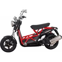
B-Bone - Scooter DAELIM - Free user manual and instructions
Find the device manual for free B-Bone DAELIM in PDF.


| Product Type | Scooter |
| Brand | Daelim |
| Model | B-Bone |
| Engine Displacement | 125 cc |
| Engine Type | 4-stroke, single cylinder |
| Fuel Type | Gasoline (unleaded) |
| Max Power | 8.5 hp (6.3 kW) at 8000 rpm |
| Max Torque | 8.5 Nm at 7000 rpm |
| Transmission | CVT automatic |
| Starting System | Electric and kick start |
| Dimensions (L x W x H) | 1900 mm x 700 mm x 1100 mm |
| Wheelbase | 1310 mm |
| Seat Height | 770 mm |
| Dry Weight | 110 kg |
| Fuel Tank Capacity | 6.5 L |
| Front Brake | Disc, 220 mm |
| Rear Brake | Drum, 130 mm |
| Front Tire | 110/70-12 |
| Rear Tire | 120/70-12 |
| Battery | 12V - 6Ah (YTX7L-BS) |
| Headlight | 12V 35/35W halogen |
| Oil Capacity (engine) | 0.8 L (with filter change) |
| Maintenance Interval | Oil change every 2000 km |
Frequently Asked Questions - B-Bone DAELIM
User questions about B-Bone DAELIM
0 question about this device. Answer the ones you know or ask your own.
Ask a new question about this device
Download the instructions for your Scooter in PDF format for free! Find your manual B-Bone - DAELIM and take your electronic device back in hand. On this page are published all the documents necessary for the use of your device. B-Bone by DAELIM.
USER MANUAL B-Bone DAELIM
ank you for purchasing an Daelim vehicle. We hope you enjoy safe riding.
ERATOR AND PASSENGER
is motorcycle is designed to carry the operator and one passenger.
WARNING
empting to change the pre-set maximum speed may cause danger and will void the Daelim warranty.
-ROAD USE
is motorcycle is designed to be used only on the road.
AD THIS OWNER'S MANUAL CAREFULLY
y special attention to statements preceded by the following words:
WARNING
icates a strong possibility of severe personal injury or death if instructions are not followed.
CAUTION
icates a possibility of personal injury or equipment damage if instructions are not followed.
NOTE
es helpful information.
nanual is an important and integral part of your vehicle. keep it with your vehicle at all times, even though your vehicle is resold.

CONTENTS
IFICATION 3
RATION INSTRUCTION 4
:ETY PRECAUTIONS 4
RIOR TO STARTING VEHICLE 5
OR SAFE DRIVING 5
PERATION 6
ORRECT ATTIRE 7
ODIFICATION 7
TTACHMENT 8
UFFLER 8
RTS LOCATION 9
TER READING AND USAGE 12
ETER 12
'ARNING AND INDICATOR LAMPS 12
ALFUNCTION INDICATOR LAMP 12
ITCH OPERATION 13
AIN SWITCH 13
TART BUTTON 13
EADLIGHT 14
ASSING SWITCH 14
'INKER SWITCH 15
ORN BUTTON 15
EQUIPMENT USAGE 16
STEERING STEM LOCK 16
SEAT LOCK 16
HOLE FOR A CHAINLOCK 16
CORRECT DRIVING OPERATION 17
STARTING THE ENGINE 17
AFTER STARTING ENGINE 19
PROPER DRIVING METHODS 20
STOPPING 21
SELF INSPECTIONS BEFORE OPERATION 23
INSPECTION OF CONCENED AREA 23
BRAKE INSPECTION 24
TIRE INSPECTION 24
FUEL CHECK 26
ENGINE OIL CHECK 27
LIGHTS AND WINKER INSPECTION 27
BULB REPLACEMENT METHOD 28
REAR VIEW MIRROR 28
FUEL LEAK INSPECTION 28
INTENANCE 29
IAINTENANCE SCHEDULE 29
IAINTENANCE PRECAUTIONS 31
IMPACT WHEN COLLISION 51
WIRING DIAGRAM (EURO2) 52
WIRING DIAGRAM (EURO3) 53
SPECIFICATION
| ITEM DATA ITEM DATA | ||||
| LENGTH × WIDTH × HEIGHT(mm) | 1,910 × 750 × 1,090 | IGNITION SYSTEM | ECU (C.D.I) | |
| WHEEL BASE(mm) | 1,360 | BATTERY CAPACITY | 12V10AH(MF TYPE) | |
| GROUND CLEARANCE(mm) | 126 | FUEL CAPACITY( l ) | 7.1 l (6.8) | |
| RESERVE FUEL CAPACITY( l ) | 1.2 l | |||
| SEAT HEIGHT(mm) | 755 | |||
| DRY WEIGHT(kgf) | 130 | TIRE SIZE | FR. | 120/70-13 |
| PASSENGER | 2 | RR. | 130/60-13 | |
| ENGINE TYPE | OIL-COOLED / AIR- COOLED4CYCLE | SUSPENSION | FR. | TELESCOPIC |
| RR. | UNIT SWING OIL DAMPER | |||
| PISTON DISPLACEMENT(cc) | 124.9 | BRAKE | FR. | HYDRAULIC DISK |
| BORE AND STROKE(mm) | 56.0 × 50.7 | RR. | HYDRAULIC DISK | |
| STARTING SYSTEM | START MOTOR | SPARK PLUG | CR8EH-9 | |
| TRANSMISSION TYPE | CVT | FUSE(A) | 15/30 (15) | |
“( )” MARKED CONTENSTS APPLY TO EURO 2 ONLY
ERATION INSTRUCTION
manual describes matters pertaining to correct operation, operation and simple maintenance of the vehicle you nased.
nsure more comfortable and safer operation, make sure to this manual carefully prior to operation.
e photographs and drawings shown in this manual may fer from those of actual vehicles due to changes in vehicle cci cations and modi cations made.
is vehicle is designed for 2 riders including the operator.
CAUTION
Do not use polluted gasoline.
Otherwise, it cause rust inside the fuel tank, and close the supply of fuel to the injector, leading to an improper engine starting or may cause serious damage to an engine.
Do use genuine oil.
Then it will protect and extend vehicle life.
Warranty does not apply to the motorcycles used in competitions or competitive trials. No motorcycle part may be tampered with, altered, or replaced with parts other than original Daelim spare parts during the warranty periody.
As far as any defect caused by contaminated gasoline or oil, the warranty will be automatically invalidated.
SAFETY PRECAUTIONS
- Careful driving and the wearing of proper attire and safety equipment are the most important factors in the safe operation of the scooter. Please obey traffic regulations and do not be hurried and careless.
- Many new vehicle owners operate their newly purchased vehicles with great care and attention to safety factors. However, after becoming accustomed to the operations are often discarded, which can lead to accidents. Please don't let this happen to you and always approach the operation of your vehicle with the safety considerations needed.
When operating the vehicle, always keep in mind and obey the notes of precaution printed on the "Safety Precaution Label" attached to the vehicle.
- Be sure to wear helmet at all time.
- Be sure to put on gloves at all time.
- Always respect speed limits where these are posted. However, always adjust your speed to the visibility, road and traffic conditions you are riding in.
- Beware of muffler after driving as it is still hot to be burnt. Especially never children touch on it.
- For safety, do not change, alteration or modification the vehicle.
- Regularly conduct specified maintenance inspections.
Brakes, Tires, Oil, Lights, Horn, Instruments
OR TO STARTING VEHICLE FOR SAFE DRIVING
not operate this vehicle with more than 2 persons
is vehicle is designed to carry an operator and one ssenger.
rforming daily inspection.
tting on protective gears. (helmet, glove, goggles, etc.)
ing the driver's licence.
terminating the path to the desired destination.


- Always hold the handlebars firmly with both hands whiling driving.
- The pillion passenger should always hold on to the suitable grab handles at the sides of the seat with both hands. otherwise, it cause severe injury or death.
- Fasten the goods tightly before driving.

natural_image
Line drawing of a person operating a motorcyclist near a building with smokestacks (no text or symbols)- Exhaust gas contains harmful substance such as carbon monoxide, Start engine in well-vetilated places.
CAUTION
- Do not keep engine idling in a closed or poorly ventilated place for a long period of time.
asoline is extremely flammable. Avoid fire in the work pace, also paying particular attention to spark. Furthermore the evaporated(gasified) gasoline is highly plosive.

ake sure to stop engine and stay away from fire when eling.
OPERATION
- Operators should naturally x bodies to keep smooth driving.
- Please check whether or not you are unnaturally strained and strung up.
- Driving pose has a great in uence on safe operation.
Please always maintain the center of your body in the middle of seat. Especially do not sit at the rear seat because it may lessen the weight of front wheel and cause trembling steering wheel. - When wanting to turn, slightly lean to body toward the direction of the turn. It is unsafe if the body is not moved in union with the vehicle.
- Curvy roads and poor, unpaved roads constantly change in surface quality. Driving on these roads can be unsafe if certain safety precautions are not followed.
- In order to safely drive through these driving conditions, anticipate coming road conditions, slow down to at least half the normal speed, and relax your shoulders and wrists while securely holding the handles.
RRECT ATTIRE
sure to wear helmet and gloves at all time for seafty. ear shirts or jackets with tight in the wheel driving. Otherwise it can be caught in the wheel to cause serious nage by overturn of vehicle.
any automobile/motorcycle accidents happen because the automobile driver does not "Look" the motorcyclist.
'ear bright or re-ective clothing.
on't ride in another motorist's "blind spot".
sure to wear dress to catch an eye to avoid any crash from mind.

WARNING
Be sure you and a fellow passenger always wear a helmet, eye protection and other protective apparel when you ride.
Not wearing a helmet increases the chance of serious injury or death in a crash.
MODIFICATION
- Modification of vehicle structure of function deteriorates manipulatability or causes exhaust noise to become louder shortening the vehicle life. These modifications are not only prohibited by law but also are the acts harmful to other people. Modifications are not covered by warranty.
ГАСНМЕНТ
cept designated attachment by DAELIM MOTOR CO., 'D., don't attach any extra lighting device, because it may use an early discharging of battery.
refully inspect the accessory to make sure it does not secure any lights, reduce ground clearance and banking gle, or limit suspension travel, steering travel or control eration.
) not add electrical equipment that will exceed the torcycle's electrical system capacity. A blown fuse could use a dangerous loss of lights or engine power.
WARNING
Improper accessories or modifications can cause a crash in which you can be seriously hurt or killed. Follow all instructions in this manual regarding accessories and modification.
MUFFLER
- Pay particular attention to fellow passenger so that he/she can prevent getting burnt by the hot muf er during travel.

natural_image
Illustration of a car dashboard with hand and earbrack, showing mechanical components (no text or symbols)
natural_image
Illustration of a park scene with people, trees, and a bench (no text or symbols)CAUTION
- Beware of muf er after driving as it is still hot to be burnt. Especially never children touch on it. And pay attention to park where pedestrian zoon.
- If haystack or vinyl is stuck to the muf er, it might be fired.
TS LOCATION

TS LOCATION

TS LOCATION

ER READING AND USAGE
TER

EL METER>
uel meter indicates the gasoline level: the fuel tank.
ine should be put in the fuel tank as as possible if the needle is resting in d area.
TANK CAPACITY : 7.1ℓ (EU2 : 6.8ℓ) ERVE FUEL CAPACITY : 1.2ℓ CEDOMETER>
ates driving speed. Keep the law limits to ensure safe operation.
OMETER>
ates total distance in kilometers led by the vehicle.
WARNING AND INDICATOR LAMPS
If the gasoline is low, the fuel warning lamp will turn on.
If the warning lamp is turn on, quickly ll the fuel tank.
WARNING
● To avoid running out of fuel, it might cause severe injury due to engine abruptly stop.
When the winker switch is operated, the winker indicator ashes in union with the ashing of the turn signals.
MIL
EMS(Engine Management System) is equipped with a self-diagnosis function in order to ensure that the engine control system is operation normally.
If this function detects a malfunction in the system, the malfunction indicator lamp immediately operates.
It gives the rider that malfunction has occurred in the system.
Normally, the malfunction indicator lamp illuminates for 3 seconds when the main key is turned on.
If the malfunction indicator lamp does not come on under these conditions, the malfunction indicator lamp may be defective.
After 3 seconds, the malfunction indicator lamp off automatically. However, the MIL blinks continuously, check the EMS system. If you are not able to check the EMS system, contact your daelim dealers.
The EMS takes fail-safe function, it enables to drive only temporary by starting even on conditioned.
TCH OPERATION
IN SWITCH

MAIN SWITCH
- ON.... Starts engine. Key can not be pulled out.
- OFF....Stops engine. Key can be placed in or taken out of the main switch.
- LOCK....Locks handle bars. Key can be placed in or taken out of the main switch.
- OPEN....When seat lock is released, key returns to its original position(OFF). Key can be placed in or taken out of the main switch.
CAUTION
- Rotate key smoothly without pressing to turn to open. When the seat lock open.
- When you park the vehicle, please lock handle bars and take out the key.
START BUTTON

natural_image
Technical line drawing of a mechanical clamp or grip assembly (no text or symbols)START BUTTON
The engine will start when the main switch is on, the brake is pressed and the start button is pushed.
CAUTION
- The engine will not start if the brake lever is not grabbed.
- Do not hold the brake lever and pull the throttle grip when the engine has started. It may damage the engine and the vehicle could abruptly start.

ADLIGHT
RNING ON HEADLIGHT>
tain switch key in "ON" position and on headlight switch.
DLIGHT SWITCH

natural_image
Technical line drawing of a mechanical component with no visible text or symbols| TCH POSITION FUNCTION | |
| × (H) | Headlight, taillight, position lamp and meter lights on. |
| (P) | Position lamp, taillight, and meter lights on. |
| (OFF) | Light turned off. |
High beam or low beam can be operated by the use of dimmer switch.

HIGH BEAM
D (HI) ..... used when needing extra light.
LOW BEAM
≡D(LO)..... used when other vehicles are present, in the city, etc.
CAUTION
- Use the high beam only in the suburban road or when the usage of the high beam not hinder the safe driving of the car ahead.
PASSING SWITCH
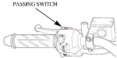
When this switch is pressed, the headlight flashes on to signal approaching cars or when passing.

JKER SWITCH

natural_image
Technical line drawing of a mechanical device with no visible text or symbolsWINKER SWITCH
s switch is turned on when the main h is in an ON position, the winker will .tc.
(R)....used when making a right turn.
(L)....used when making a left turn.
CAUTION
- The winker switch does not automatically turn back to its original position after completing the turn. Please set the switch back to its center position after turning.
HORN BUTTON

natural_image
Technical line drawing of a mechanical device with no visible text or symbolsHORN BUTTON
The horn will sound if the horn button is pressed when the main switch is in an ON position.
IPMENT USAGE
EERING STEM LOCK
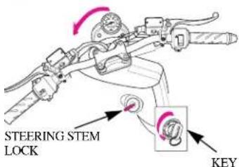
parking, make sure to lock handle to prevent theft of the vehicle.
CKING>
ck the steering, turn the handlebars e way to the left, turn the key to < while pushing in. Remove the key.
LOCKING>
lock the steering, turn the key to the position.
CAUTION
Check to see if the steering stem is locked securely by lightly moving to the left and light. Pay attention not to obstruct traffic when the parking.
- The seat automatically locks when the seat is pushed in its downward position,
- Lightly pull upward on the seat to make sure the seat has been properly locked.
- Turn the main switch key from OFF to OPEN to open the seat.
CAUTION
- As the seat automatically locks, take special care not to accidentally leave the key in the trunk.
- When the seat lock is out of order, do not operate it further and inspect it in the closest authorized repair center.

HOLE FOR A CHAIN LOCKSEAT LOCK
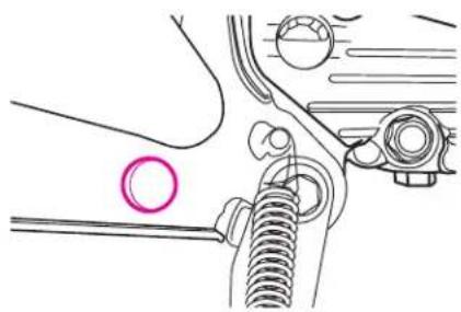
When main stand is in use, a chain lock can be put through this hole and through rear tire or a nearby xed item to prevent theft.
natural_image
Mechanical assembly diagram showing a spring-loaded connector and housing (no text or symbols)
ake sure to check the oil, gasoline, .., before starting the engine. case ensure that the main stand is in a wn position when starting the gine.
CAUTION
Take sure that the rear wheel is locked when starting the engine to prevent an unexpected quick start of the vehicle.
ocking is not possible if the rear heel brake is not adjusted correctly.
ive with care for both safety reasons 1 longer vehicle life.
r 1 month (or 1,000km) after pur- asing the vehicle, drive moderately oiding fast starts and fast celeration.
STARTING THE ENGINE
① Lock the rear wheel.

natural_image
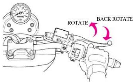
Illustration of a hand holding a mechanical device with a pink arrow indicating direction (no text or symbols present)- Be sure to grab the front / rear brake lever when starting the engine.
② Turn the main switch to an ON position.
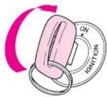
③ Open the throttle grip to 1/8\~1/4 of a rotation, and press the starter button.
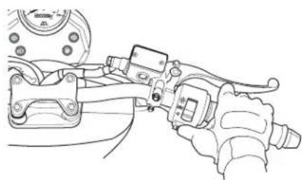
natural_image
Technical line drawing of a mechanical clamp or grip assembly (no text or symbols)CAUTION
- Immediately release the starter button as soon as the vehicle has started.
- Do not press the starter button when the engine is running.
This can damage the start motor.
the engine is hot and does not start or pressing the starter button for 3\~4 seconds, rotate the throttle grip to 1/8 \~ 1 of a rotation and try again. This ll allow easy starting.

- It is possible that starting will be more difficult if the vehicle has not been used for a long period of time or if the fuel hole is plugged up(starting problems even when there is sufficient fuel in the fuel tank may be an indication of a plugged fuel hole). When this happens, do not rotate the throttle grip and try the starter button a few times.
CAUTION
- Do not keep the statter button pressed for more than 5 seconds at a time. Release the starter button for approximately 10 seconds before pressing it again.
- Keep holding rear brake until start.
- Exhaust has contains harmful substance such as carbon monoxide.
Start engine in well-ventilated places.
4 When the engine is cold (morning or winter or the vehicle has not been used for a long period of time) let the engine idle for a short period allow the engine to warm up.
WARNING
- Never run the engine in an enclosed area. The exhaust contains poisonous carbon monoxide gas that can cause loss of consciousness and lead to death.
- While the scooter is on its stand you should never apply full throttle: if the rear wheel touches the ground the scooter would set off at full speed. (Remember that the scooter has a centrifugal automatic speed control)

'ER STARTING ENGINE
Fold the main stand.
sh the vehicle forward to fold the tin stand and make sure that the ke lever does not become released ring this operation.

natural_image
Illustration of a person riding a motorcycle with a red arrow indicating direction (no text or symbols)CAUTION
to not excessively open the throttle until you actually start the driving operation of the vehicle.
② Get on the vehicle.
- Mounting should be done from the left side, and you should sit squarely on the seat. Leave either one foot or both feet planted on the ground
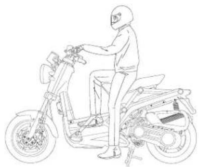
natural_image
Line drawing of a person riding a motorcycle, no text or symbols presentCAUTION
- Keep holding rear brake lever before starting.
3 Release the squeezing tension on the rear brake lever and slowly begin to rotate the throttle grip to allow for a slow and easy start.

natural_image
Technical illustration showing mechanical assembly with arrows indicating motion (no text or symbols)CAUTION
- A quick rotating of throttle grip will cause the vehicle to move forward abruptly.
- If the engine RPM will not turn down after throttle grip return to original position, stop operating and inspect it registered repair center nearby.
OPER DRIVING METHODS
fore entering traffic, use the correct n signal to foreward other drivers of ur intentions.

natural_image
Line drawing of a motorcyclist riding on a road with directional arrows indicating motion (no text or symbols)- If the throttle grip is rotated......
The speed of the vehicle increases. Please rotate the throttle grip slowly. When climbing a hill, the throttle grip need to be rotated further to give the vehicle more power.
- If the throttle grip is allowed to rotate back......
Speed decreases. This can be done slowly or quickly, depending on how quickly you need to decelerate.
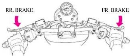
- Allow the throttle grip to rotate back to its beginning position and then squeeze the brake levers.
- If is best to operate the brakes by first lightly squeezing the brake levers and then changing to a more rm squeeze.
CAUTION
- If only one of the brakes is used, it is possible for the vehicle to sliding.
brakes should never be denly applied and the handle s should never be suddenly ned.>
dden braking or turning can cause vehicle to slide and tip over. is especially dangerous to perform lden braking on wet roads or in rainy rather as the tires can lose traction and slip easily.

natural_image
Line drawing of a person riding a motorcycle with motion lines indicating speed (no text or symbols)- More braking distance is needed when driving on wet roads or in the rain. Reduce speed and be sure to initiate the braking operation sooner than when driving in normal conditions.
- On downgrades, allow the throttle grip to rotate back to its initial position to reduce speed, and apply the brakes and drive slowly down the hill.
- It is possible for the brakes to temporarily lose operative ability after driving through a puddle or when driving in the rain. To ensure that the brakes are operating properly, slow down(after checking for other vehicles) and while driving slowly, lightly apply the brakes to rid the brakes of any excess water and to dry them.
- Be extremely careful when driving in the snow or on icy roads. When driving in these conditions, both the tires lose much of their traction and the rear tire can slip when opening the throttle.
STOPPING
When approaching the desired stopping area.
- Activate the proper winker, and after checking for other vehicles, slowly turn into the area in which you want to stop.
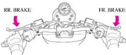
- Allow the throttle grip to rotate completely back and apply the front and rear brakes. The brake light will shine to alert vehicles in back of you that you are stopping.
After the vehicle has come to a complete stop.
turn the winker switch to the center sition and turn the main switch to 'F. This will turn the engine off.

CAUTION
Do not rotate the main switch key while driving. If the main switch is turned to an OFF or LOCK position, the electrical system will not operate. Operating the main switch key while driving can be very hazardous. Only turn the main switch key to OFF or LOCK position after completing topping the vehicle.
③ Dismount on the left side and lower the main stand on a at surface.
- Be sure to park in an area that is free of traffic. Also, the vehicle can tip over if the main stand is not placed on a stable and at surface.
- The main stand is lowered by grasping the handle bars with the left hand, holding the rear carrier with the right hand, and stepping rmly on the stand with the right foot. In this position, lift the rear carrier upward, which will secure the main stand.

natural_image
Line drawing of a person working on a motorcycle with an inset showing close-up of the wheel (no text or symbols)4 To prevent theft, be sure to lock the steering when parking.
CAUTION
- Park in a safe area that will not block traf c. When you parked the vehicle after driving, make sure foot the vehicle beyond man's reach because engine and muffler are still hot.
- Park the motorcycle on firm, level ground to prevent it from failing over.
- If you must park on a slight incline, aim the front of the motorcycle uphill to reduce the possibility of rolling off the side stand or overturning.
: INSPECTIONS BEFORE OPERATION
inspect the vehicle and have regular tenance inspections for increased and the prevention of accidents. lar maintenance inspections should rformed even if the vehicle has not used for a long period of time.
nspections before operation should rformed on a daily basis prior to ting the vehicle.
spections of concerned Area ake inspection re inspection el check gine oil check ghts and winker inspection ck mirror inspection el leak inspection cense plate inspection rottle grip inspection.
CAUTION
Observe safety rules when conducting inspections.
- Exhaust gas contains harmful substance such as carbon mono-xide. Do not carry out inspections on vehicle in closed places, or in poorly ventilated places, with engine running.
- Conduct inspections on flat, solid ground with the stand erected.
- Be careful of burns when conducting inspections immediately after engine is stopped because the engine and muf er are hot.
- Stop engine and remove the key prior to the vehicle maintenance service.
- Use appropriate types of tools.
- If you are unable to correct trouble even after you make adjustment or correction, contact authorized maintenance shops, dealers or designated repair shops for necessary inspection and repairs.
INSPECTION OF CONCENED AREA
- Check areas which caused for concern when last operating the vehicle.
- If happened, contact authorized maintenance shops for necessary inspection and repairs.
AKE INSPECTION
itly squeeze the brake levers until on is felt to check for an appropriate nt of free play. No free play in the levers or overly loose brake levers indication of a problem in the brake n.
AKE LEVER FREE PLAY: 10\~20mm

CAUTION
specified brake lever free play must be maintained. Excessive free play may cause long stopping distance, rake operational fault and slow reacting time resulting in the dangerous situation and insufficient free play may cause short stopping distance and damage brake system(pad, lining, etc.)
This is checked by placing the vehicle on its main stand on a flat surface. Make sure that the handle bars are at a horizontal level. Check to see if the uid is below the LOWER level.
If brake fluid is significantly low, this may indicate that there is leakage in the brake system. Inspect the brake hose to check for leaks.

CAUTION
- If the brake fluid is remarkably lower than the specified level, inspect not only brake uid but also check the front brake pad for wear.
TIRE INSPECTION
Check for an appropriate level of air pressure by examining how the tire sits on the ground.
If you notice any abnormalities in the shape of the tire with regard to the area contacting the ground, use a tire gauge to check tire pressure and adjust the tire pressure to the appropriate level.
| SIZE | FRONT | 120/70-13 | |
| REAR | 130/60-13 | ||
| TIRE PRESSURE (kgf/dml) | DRIVER ONLY | FR. | 1.75 |
| RR. | 2.00 | ||
| DRIVER & PASSENGER | FR. | 2.25 | |
| RR. | 2.25 | ||
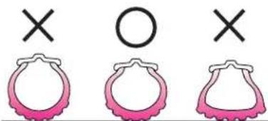

ACKS/DAMAGE>
a tire tread and sides for cracks and ge.

NORMAL WEAR>
k tire tread for signs of abnormal

Check tire tread and sides for nails, rocks, etc. That might have become wedged in the tire.

- Check the wear indicator (wear limit marking) to see if there is an insuf cient amount of tread remaining.
- If the indicators are visible, replace tire with a new one.
WEAR INDICATOR
(WEAR LIMIT MARKING)
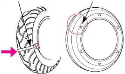
natural_image
Technical illustration of a mechanical bearing assembly showing two views (top and side) with arrows indicating direction and a pink arrow pointing to a specific component.WEAR INDICATOR LOCATION MARKING
CAUTION
- If air pressure is inadequate or if there are cracks, damage or abnormal wear on tires, it may cause trembling steering wheel and flat tire.
- Insufficient air pressure may cause the heavy steering wheel making handling difficult, fuel over consumption and the excessive wear of tire outer area and excessive air pressure may cause easier wheel handling and lower fuel consumption. But it may also cause the excessive wear of tire center area.
- This vehicle is equipped with tubeless tires. If you have flat tires, please contact authorised maintenance shops for inspection.

EL CHECK
ECK>
c gasoline to see if there is a sufficient int of gasoline to reach your ation.
ice the main switch to "ON" position. the fuel meter needle indicates E urk (red portion), fill fuel tank with soline as soon as possible.
SERVE FUEL CAPACITY : 1.2 /
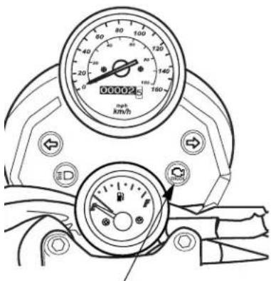


FUEL WARNING LAMP)
- Open the key cover on fuel tank cap, and turn the key clockwise to remove the cap.
- Fill the tank with gasoline until it reaches the bottom of the level plate.
- Press the cap firmly, and pull out the main key.

CAUTION
- Gasoline is extremely ammable and is explosive under certain conditions. Refuel in a well-ventilated area.
- Make sure to stop engine and stay away from fire when refueling.
- Do not fill gasoline past the level plate. Gasoline may leak out of the fuel tank when replacing the fuel tank cap if too much gasoline is put in the fuel tank.
- Don't fill low grade gasoline. Using it can cause damage (bending, getting worn, etc.) to combustion chamber and parts of fuel.
- Do not close the fuel cap with excessive strength. It may cause the damage of the cap and the rubber packing resulting in the leak of fuel and may cause fire in case of electrical short or the overturn of the vehicle.
- Avoid repeated or prolonged contact with skin or breathing of vapor.
- Keep out of reach of children.
GINE OIL CHECK
ECK>
il level must be maintained between oper and lower level marks on the glass.
ind the motorcycle on the main stand level ground.
art the engine and let it idle for proximately 2\~3 minutes.
eck the engine oil level.
required, add the specified oil. Do not erfill.

to not allow the engine to stay at a low level. The engine will become severely damaged if the vehicle is driven without the engine oil.
LIGHTS AND WINKER INSPECTION
Turn a main switch "ON". Check the lights for proper operation by operating the switch and also a lens for damage or contamination.
CAUTION
- The lighting head light emits very hot heat. If you touch with naked hand, it may be burned.
- When replacing head light lamp, stop lame and winker lamp, use only a bulb of rated capacity. Using a lamp exceeding the rated capacity can cause over-discharge of battery and wire burning. It can lead a fire.
- If the head light is turned off due to aging while driving at night, it will cause an accident by obstructing driver's view. Check the condition daily.
- If the tail light is off while driving at night, it will cause an accident by failure of notice by the other drivers. Check the condition daily.
Turn a main switch "ON". Check the lamp for proper operation (front/rear and right/left) and sound by operating the switch, and also a lens for damage or contamination.
Turn a main switch "ON". Check a stop lamp for proper operation by operating the front wheel and the rear wheel brakes, and also a lens for damage or contamination.

LB REPLACEMENT METHOD
sure to turn a main switch "OFF" or to replacement of a bulb. e only a bulb of rated capacity. ter replacement with new bulb, eck for proper operation.
CAUTION
Care is to be taken to avoid leaving fingerprints on a headlight bulb. Tailing to observe this may cause early damage of the headlight bulb resulted from concentration of heat. We sure to wear clean gloves when replacing a bulb. If touched to it with are hands, clean it with a cloth soaked with alcohol to prevent from early damage.
ADLIGHT BULB>
k to see if the switch has a contact em, before replace the bulb.
osen 4 washer screw and remove the adlight.
ess the socket spring, turn counter ck wise.
③ Remove the headlight bulb. ④ Replace the bulb with new one. Install in the reverse order of removal.
HEADLIGHT BULB : 12V 35/35W
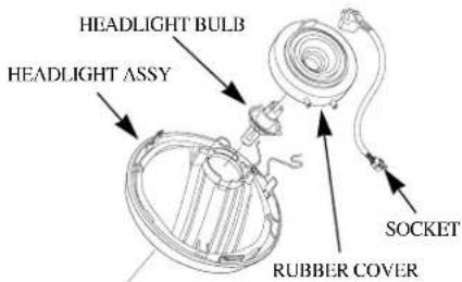
①Loosen two tapping screws to disassemble a lens.
② Press a bulb with a light force and rotate it to counterclockwise to disassemble it.
③Replace it with new bulb. Install in the reverse order of removal.
FRONT / REAR WINKER BULB :
12V 10W X 2

REAR VIEW MIRROR
Check the objects at the back are well noticed when seating on a driver's seat, and also mirror for damage or contamination.
FUEL LEAK INSPECTION
Check there is no gasoline leakage from fuel tank, hoses, carburetor, etc.
ITENANCE
INTENANCE SCHEDULE
m the Self Inspections Before Operation at each scheduled maintenance period.
SPECT AND, CLEAN, ADJUST, LUBRICATE OR REPLACE IF NECESSARY
EPLACE
JBRICATE
LEAN
| EM\FREQUENCY | ODOMETER READING(NOTE1) | REMARK | ||||||
| ×1,000Km | 481216 | |||||||
| MONTH | 6121824 | |||||||
| FUEL LINE | I | I | I | I | I | |||
| THROTTLE OPERATION | I | I | I | I | I | |||
| AIR CLEANER ELEMENT | R | R | R | R | ||||
| SPARK PLUG | I | I | I | I | I | |||
| ENGINE OIL | R | R | R | R | R | |||
| ENGINE OIL FILTER | R | R | R | R | R | |||
| OIL FILTER SCREEN | C | C | C | C | C | |||
| TRANSMISSION OIL | R | R | R | |||||
| BRAKE FLUID | I | I | I | I | R | |||
| VALVE CLEARANCE | I | I | I | I | I | |||
| (FUEL STRAINER) | I | I | I | R | Apply to EU2 ONLY | |||
| (CARBURATOR IDLE ROTATION) | I | I | I | I | I | Apply to EU2 ONLY | ||

| FREQUENCYITEM | ODOMETER READING(NOTE 1) | REMARK | ||||||
| Km 1,000Km 4,000Km 8,000Km 12,000Km | 16,000Km | |||||||
| MONTH 1 | 6 12 18 24 | |||||||
| ★ | BRAKE SHOE / PAD WEAR | I | I | I | I | I | ||
| BRAKE SYSTEM | I | I | I | I | I | |||
| ★ | BRAKE STOP SWITCH | I | I | I | I | I | ||
| ★ | HEADLIGHT ADJUSTMENT | I | I | I | I | |||
| ★ | CLUTCH SHOE WEAR | I | I | I | I | |||
| ★ | SUSPENSION | I | I | I | I | |||
| ★ | BOLTS, NUTS, FASTENERS | I | I | I | ||||
| ★ | WHEELS / TIRES | I | I | I | I | I | ||
| ★ | STEERING HANDLE BEARING | I | I | I | ||||
| ★ | DRIVE BELT | I | I | I | I | |||
| ★ | WEIGHT ROLLER | I | I | I | I | |||
| ★ | SLIDE PIECE | I | I | I | I | |||
If you do not have the appropriate tools or information to conduct maintenance, or if you feel you are not capable to perform maintenance on this vehicle, contact authorized dealers or repair shops for maintenance and repairs.
To ensure safety, inspections and maintenance of these parts must be carried out by dealers, or repair centers.
TES : (1) At higher odometer readings(16,000Km), repeat at the frequency interval established here.
(2) Service more frequently when riding in unusually wet or dusty areas.
(3) Replace every 2 years, or at indicated odometer interval, whichever comes first. Replacement requires mechanical skill.

INTENANCE PRECAUTIONS
following is an explanation of correct ction methods, cleaning and parts cing. Please always refer to this n when wanting to inspect or repair vehicle.
CAUTION
always observe safety rules when performing maintenance on the vehicle.
choose a at surface and make sure the main stand is in a secure down position.
se correct tools.
conduct engine maintenance with the engine key out of the ignition.
e careful around the engine and ruffler when performing mainte- ance as these areas can become ktremely hot.
after self maintenance, the waste material must be packed in the specified container and entrusted disposal to the authorized disposal company.
- Check that the uid level is above the LOWER level mark with the motorcycle in an upright position.
-
Brake fluid must be added to the reservoir whenever the fluid level begins to reach the LOWER level mark.
-
Remove the screws.
-
Clean dust and other foreign materials around reserve tank to prevent foreign materials from falling inside tank.
-
Remove the screws and take oil cup cap, diaphragm plate, diaphragm off.
-
Replenish recommended brake oil to the upper level inside reserve tank.
- After replenishing bralce oil and when assembly, pay attention to assembly direction and jammed of diaphragm. Install in the reverse order of removal.

CAUTION
When adding brake fluid, be very careful not to allow foreign materials to enter the reserve tank.
foreign materials can clog the system, causing a reduction or complete loss of braking ability.
Do not ll past upper level.
his can cause brake uid to leak out of the reserve tank.
Do not let brake uid contact vehicle parts as this damages painted areas. If oil contacts parts, quickly clean the uid off using a dry cloth.
Ise recommended brake fluid as ther types can undergo chemical hanges.
f brake fluid is exceedingly low, this can be indication of damage to the brake system.
leak in the brake system can lead to reduced braking efficiency and possible loss of braking ability.
BRAKE HOSE, PIPE LEAKAGE, DAMAGE, ASSEMBLY STATE
Visually check for fluid leaks or damage and, using a spanner, check joints and clamps for clearance.
Also, check hose and pipe protective parts to see if they contact other parts when turning the handle bars or due to vibration when driving. (Bent, Distorted, Tear)
Brake pad wear depends upon the severity of usage, the type of riding, and road conditions. (Generally, the pads will wear faster on wet and dirty roads.)
Inspect the pads at each regular maintenance interval (page 30).
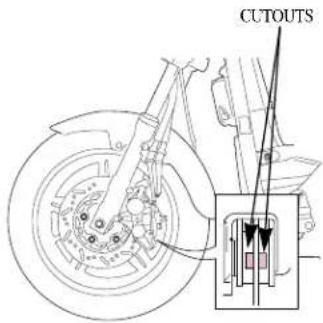
WARNING
- Check to see if the pad out of the standard. If the pad exceed the breaking point, it may cause severe injury or death due to reduced braking efficiency and possible loss of braking ability.

ANGING ENGINE OIL
the engine oil is contaminated, the life gine will be remarkably shortened. the proper oil level, kind and replacing
ice the vehicle on a flat surface, and 2 (warm up) the engine 2\~3 minutes.
op the engine, separate the oil level age, place a vessel under the engine, I remove the oil drain bolt to drain the
move the adjusting hole cap, and clean oil filter screen.
eck the condition of O-ring of oil filter een.
stall the oil filter screen, spring, usting hole cap.
tall the oil drain bolt.
eck the oil level gauge, and add the gine oil until it reaches the specified el (between max and min)
stall the oil level gauge, and idle the gine for a while.
ait for 20\~30 seconds after stopping the gine, check again the oil level gauge.
EN CHANGING OIL : 0.8 l
EN CLEANING THE FILTER SCREEN :
\~ 0.75

[SPECIFIED GENUINE OIL]
Don't fill the low grade oil. Using it can cause damage to engine, and can't receive the warranty. Use only the genuine oil.
Genuine oil: Motics 4 oil
SF, SL grade (SAE : 10W40)
![DAELIM B-Bone - [SPECIFIED GENUINE OIL] - 1](/content/2026/06/1371498/images/b97fc8b90627c8ce32692ac99f8d4625416b06ec2228f31c8171de233c525a9d.jpg)
WARNING
- If changing the oil by loosening the oil drain bolt, always clean the oil liter screen.
CAUTION
- When changing the engine oil immediately after stopping the engine, be careful not to be burned the hot oil.
- When refueling, make sure not to enter the dirt into oil pouring port.
- If the oil overflows, wipe it clearly.
- Do not fill the oil past the level plate. It can cause damage to engine.
- Don't fill the low grade oil. Using it can cause damage to engine and parts. If the engine is stuck while traveling due to this, it may lead death or serious injury. Use only the genuine oil.
- Do not pour the 2 cycle engine oil. Using it can cause serious damage to engine. If the engine is stuck while traveling due to this, it may lead death or serious injury.
- If the tire is stained with oil while or after refueling, the vehicle may slip while traveling to cause roll over.
- Do not discard the engine oil other than specified place. It will bring environmental contamination, and be brought under the law.
ANSMISSION OIL INSPECTION
urt the engine and let it idle for a few nutes.
op the engine and put the motorcycle its mainstand on level ground.
eck to see if transmission oil leaks t of the transmission case.
I the recommended oil when you ed.

RECOMMENDED OIL : SAE80W-90
OIL CAPACITY : 0.15 L
CAUTION
- When draining the oil, make sure that all of the oil is removed.
- The engine can be harmed if there is too much or not enough oil.
- Do not use low-quality oil. These oils can change quality overtime and can cause damage.
Check to see it transmission oil leaks out of the transmission case.

natural_image
Diagram of a car brake system showing a piston and wheel assembly with a pink liquid dripping (no text or labels)
E PRESSURE INSPECTION
the tire pressure using a tire gauge.
k tire pressure when the tires are
| ZE | FRONT | 120/70-13 | |
| REAR | 130/60-13 | ||
| TRESSUREf/oml | DRIVERONLY | FR. | 1.75 |
| RR. | 2.00 | ||
| DRIVER &PASSENGER | FR. | 2.25 | |
| RR. | 2.25 | ||

natural_image
Line drawing of a hand holding a circular gauge or dial, with motion lines indicating speed (no text or symbols)WARNING
air pressure is inadequate or it there e cracks, damage or abnormal wear n tires, it may cause trembling eering wheel and flat tire.
BATTERY INSPECTION
When removing the pillion seat and open the battery box cover, you can find the battery. If the battery terminal is polluted or in-rust, separate battery and clean it.
- Battery terminal in rust with white powder should be cleaned with warm water.
- In case of serious rust of battery terminal, disassemble the battery cord and grind it with wire brush or sandpaper.

natural_image
Technical line drawing of a mechanical assembly with labeled components (no text or symbols)CAUTION
- Turn the ignition switch OFF before disconnecting the terminal from the battery. Disconnect the negative(-) terminal lead from the battery first. When connecting, connect the positive(+) terminal lead first. If you work in reverse order, short circuit will occur resulting in fire.
- Make sure that terminals do not contact with other adjacent parts when handling (+), (-) terminals. Contact with other parts may cause spark resulting in electrical equipment malfunction, fire and electric shock.
- Do not apply excessive impact. When handling the battery, stay away from flammable materials.
- If the electrolyte contact with terminal, it will be corroded earlier.
- The battery is shield type, so do not disassemble the pouring plug.
- When not using vehicle during a long time, take off the battery from the vehicle to keep from self-discharge and electric discharge. Put the battery in a well ventilated place after charging fully. In case it isn't available to take battery off from the vehicle, disconnect (-) terminal.
CAUTION
/hen using the battery without cover, (-), (-) terminals may be connected to cause short circuit resulting in fire. /hen handling the battery, stay away from flammable materials.
our battery is a maintenance-free type to check or refilling of electrolyte will not be required. If there is any nonnormal, contact to Daelim service center.
you reform the battery for car, battery will be improperly installed to cause short circuit resulting in fire.
' the electrolyte gets into your eyes or skin, it'll cause a serious injury.
to not discard the battery other than specified place. It will bring environmental contamination, and be brought under the law
FUSE REPLACEMENT
Turn off the main switch to see if the fuse is severed. If the fuse is severed, exchange the fuse into a fuse with same capacity.
- Fuse is installed in fuse box around the battery.
- To change a fuse, first take off fuse cover. Then, remove the disconnected fuse, and insert the reserved fuse with same capacity.
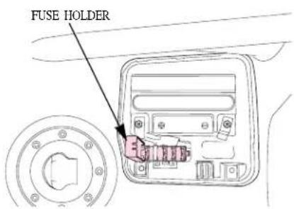
- If the fuse immediately becomes severed after being changed with the new one, check another problem of the electric system. Contact to Daclim service center.


| Fuse A | 30A | Charging, combi S/W,regulator |
| Fuse B | 15A | Winker relay, meterlighting, horn, headlight(LO/HI), front/rear stopswitch, taillight, fuel meter |
| Fuse C | 15A | Ignition coil, EcuO2 Sensor |
| Fuse D | 15A | Ecu, Fuel pump relay |
o not use screw driver or other metal arts to remove the fuse, as short circuit can be occurred to cause damage to electric system.
o not use a fuse having a larger poltage, as the wire can become overheated and damaged.
Then replacing any of the electrical parts (lights and gauges), be sure to replace them with the recommended parts. Using different parts can lead to the fuses burning out or damage to the battery.
Then washing the vehicle, take special care not to allow to be splashed the area of the fuses.
AIR CLEANER ELEMENT INSPECTION
① Loosen the 6 washer screws and 1 flange bolt, and remove the tube clip and air cleaner case cover.
② Inspect the air cleaner element.
③ If the air cleaner element is excessively dirt or damaged, replace it with a new one.

CAUTION
- If the air cleaner element is inadequately assembled, dust and other waste materials can directly enter the engine. This results in increased cylinder wear and reduced power, and reduced durability of the engine.
- When washing the vehicle, be careful not to allow water to get into the air cleaner. Difficulties in starting the engine may result if this happens.
- If the engine start is failed during rain or after driving across water pool, check to see if the water is in litrated in the air cleaner and clean it.
- Do not drive in the flooded area. If the water enters the air cleaner or engine, the vehicle may be subjected to the rear-end collision due to the power failure.

BLE RUBBER PART
ber boots is assembled on the cable ect the inner cable.
sure that this part is placed firmly d the correct part of the cable. When ng the vehicle, do not directly spray on to the rubber boots or scrub it brush. Use a dry cloth to clean this

k the installing condition of rubber daily. After adjusting the free play bottle grip, never forget to place the r boots to the original position.

WARNING
- Infiltration of the foreign materials or water caused by damage of rubber boots (disengagement, tearing, etc.) may cause freezing in winter season resulting in faulty operation. It may lead death or serious injury by decreasing of sudden acceleration and braking force due to engine rpm.
- If any damage is found, replace with the new on immediately.
SPARK PLUG
If electrode is stained or clearance is not right, satisfactory spark is not produced.
Clean and make adjustment.
- Remove the spark plug cap.
- Clean around the plug.
• Using a plug wrench, remove the plug.

natural_image
Technical line drawing of a mechanical component with arrows indicating direction (no text or symbols)SPARK PLUGSPARK PLUG CAP


ean plug with plug cleaner.
neck electrode for wear and rosion. If the ends become round, place it with a new one.
neck the plug gap using a feeler age.
JG GAP : 0.8\~0.9mm>
ghten with hands until the plug sher touches cylinder head.
NDARD PLUG : CR8EH-9>
new plug is installed, turn 1/2 and hten using a plug wrench.
plug is reused, turn 1/3\~1/4 and hten.
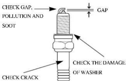
HANDLING FOR POOR STARTING
During cold season or when frequent short-distance traveling, the starting may be poor and even the engine will be OFF. this may be prevented by use of spark plug. The spark plug of this vehicle is equipped as standard when delivery. However, the starting will be poor if the vehicle is continuously driven under low speed.
CAUTION
- If plug of different maker or different heat value is used, it causes unsatisfactory engine starting, inadequate engine revolution and output deterioration.
- After driving, the spark plug become very hot. When inspecting, pay attention not to be burned.

E STAND INSPECTION
ect main stand and place vehicle in right position on level ground.
eck the spring for damage or loss of sion and the side stand assembly for edom of movement.
eck the side stand ignition cut-off stem;
?ut the side stand up.
Start the engine.
Lower the side stand. The engine would stop as you put the side stand own.
the side stand system does not erate as described, inspect it in the ofest authorized repair center.

CLEANING
- Make sure to stop the engine prior to car washing.
- Be careful not to allow water to enter the muffler during the washing. Water inside the muffler may cause an improper engine starting or rust occurrence.
- Do not let water get inside the braking system during the washing, as water inside the brake system may weaken the braking power. Upon completion of washing, select a safe place where there is no traffic obstruction, and start the vehicle.
Lightly apply the brake while driving at a slow speed and check the braking power. If the braking power has been weakened, apply brake lightly while driving at a slow speed to dry up the brake system.
- Take precautions when waxing the vehicle. Excessive polish of the painted section and/or the resin part with compound wax might damage the painted section causing discoloration of the affected area.
preserve the finish of metal parts and ntwork, wash and clean your motorcycle egular intervals, anyway according to the d conditions you ride in.
especially during winter period through road t a continuous cleaning of the vehicle is necessary so that remove the road salt. Use excic products only.
'oid aggressive detergents or solents
- Do not wash your motorcycle right after use. When the motorcycle is still hot, water drops will evaporate faster and spot hot surfaces.
- Do not use high pressure water jets.
- Never aim the nozzle direct at wheel bearings, front fork seals, electric items, air inlets or exhaust pipe ends.
- Clean off stubborn dirt or exceeding grease from engine parts using a degreasing agent.
- Be sure to avoid contact with drive parts (chain, sprockets, etc)
Rinse with warm water and dry all surfaces with chamois leather.

natural_image
Illustration of a person using a motorcycle to adjust the engine compartment, with no visible text or symbols.STORAGE GUIDEGENERAL CLEANING
Extended storage, such as for winter, requires that you take certain steps to reduce the effects of deterioration from non-use of the motorcycle.
In addition, necessary repairs should be made BEFORE storing the motorcycle; otherwise, these repairs may be forgotten by the time the motorcycle is removed from storage.
- Empty the fuel tank into an approved petrol container using a commercially available hand siphon or an equivalent method.
- If storage will last more than one month, carburetor draining is very important, to assure proper performance after storage.
AME AND ENGINE NUMBER
e frame number is stamped on the nt central part of the frame.
e engine number is stamped on the per part of the right crankcase.
e frame and engine numbers will be ed as the basis of recovering the nicle when is stolen.
cord the frame and engine numbers ong with the vehicle license plate mbers and keep them separately m the vehicle.
FRAME NUMBER

natural_image
Technical line drawing of a mechanical component with a circular feature and directional arrow (no text or symbols)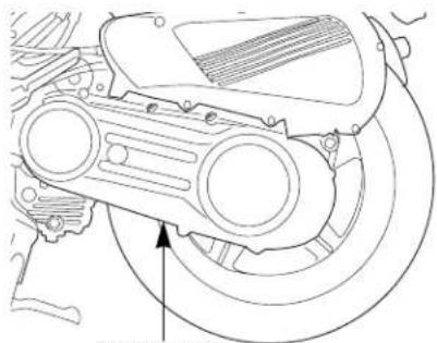
natural_image
Technical line drawing of a mechanical component with no visible text or symbolsENGINE NUMBER
/ING METHOD
IVING POSITION
appropriate driving position is most important thing to ng safely.
Eyes :
- Look at the front direction widely.
Shoulders :
- Relieve the tension.
Arms :
- Relieve the tension and bend arms to inside and let them act as the spring.
Hands :
-Grip the handle the position away from the inside end of the handle with distance of one finger to facilitate the operation of the switch and lever.
Wrist :
- Keep the state to act freely without applying excessive force to the shoulder and arms.
Knees / Feet :
- Place the feet to face the front parallel and make the step bar be placed in the center of feet.

ECAUTION WHEN DRIVING
cure the safe distance.
ive protectively.
not obstruct the traffic.
not drive on the pedestrian way or walkway.
ive on the left driveway when passing away.
ike sure that you can apply the brake anytime.
ways apply the brake when stopping temporarily.
not drive excessively long distance and take enough break.
- If any abnormality is found, stop driving and contact service center to inspect the vehicle.
- Restart the vehicle after 2\~3 min when it is turned over.
• Always turn on the headlight at night. - If any abnormality is found, stop driving and contact service center to inspect the vehicle.
- Restart the vehicle after 2\~3 min when it is turned over.
• Always turn on the headlight at night.
ARTING
: to starting always look around to avoid accident.
Get on the vehicle after pulling back the stand.
Start driving slowly after turning on the winker and releasing the brake while ensuring the safety around the vehicle.
CAUTION
Return the side stand to its original position. Keep driving without doing this may cause turnover accident.
Drive the vehicle only on the driveway. Driving on the walkway can cause accident. Also, if the wheel is transformed when advancing directly to the walkway, the vehicle can be overturned resulting in injury of the driver due to the driving instability.
Overspeed driving on the unpaved road can cause the vehicle to be overturned resulting in injury of the driver due to the driving instability.
Do not drive in the gravel road. If any gravel enters the wheel or engine case, the vehicle can be overturned resulting in injury of the driver.
If possible, do not drive close to the sea or on the road where calcium chloride is treated.
The muffler, external parts and welded parts can be corroded rapidly, and also in case of damage of the frame, the vehicle can be overturned resulting in injury of the driver.

natural_image
Three technical line drawings showing a person operating a motorcycle, with no visible text or symbols.basic principle of turn is balancing using the centrifugal e which makes vehicle go outside and the gravity which es vehicle fall inside.

natural_image
Illustration of two people riding scooters with curved arrows indicating motion (no text or symbols)The centrifugal force increases in inverse portion to the radius of a curve and in portion to the square speed. Decelerate prior to entering the curved way to reduce the centrifugal force.

OSITIONS OF TURNING
basic principle of turn is balancing using combined force of centrifugal force and the gravity.
3 positions require straightening the head and keeping the horizontally.
EAN-WITH >
is a turning position with motorcycle and driver in a line. position is the most natural and exact, so driver must learn roughly.
This is a turning position with driver leaned inside more than motorcycle. This position is adequate to drive on the rained or slippery road because it has best road holding.
However, special attention is required because front visual field is poor when driver leans inside more than motorcycle.

natural_image
Line drawing of a person riding a motorcycle with visible engine and wheel (no text or symbols)
natural_image
Line drawing of a person riding a motorcycle with visible engine and wheel (no text or symbols)
TURNING METHOD
EAN-OUT >
s is a turning position with motorcycle leaned inside e than driver, which is opposite to the lean-in position. n this position, quick turn is well performed and driver can in wide front visual field adequate to drive on the rained or py road because it has best road holding. However, special tion is required because there is danger of slipping on the holding road.

natural_image
Line drawing of a person riding a motorcycle with no visible text or symbols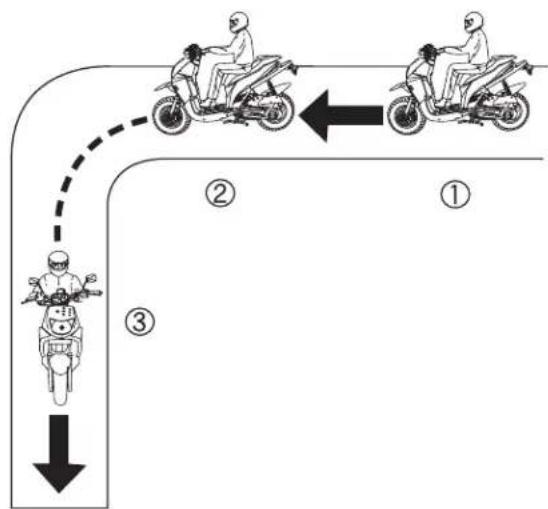
flowchart
graph TD
    A["Top: Motorcyclist at top"] --> B["Left: Route to Road"]
    B --> C["Right: Route to Road"]
    D["Bottom: Motorcyclist at bottom"] --> E["Right: Route to Road"]
    style A fill:#f9f,stroke:#333
    style B fill:#ccf,stroke:#333
    style C fill:#cfc,stroke:#333
    style D fill:#fcc,stroke:#333
① Turn the throttle grip to its original position and decelerate using both front and rear brakes.
② Lean the vehicle toward inside of turn circle while driving slowly at constant speed.
③ Accelerate gradually.
ECAUTION WHEN TURNING
not drive inside of large truck's turn circle.
EAD ANGLE ZONE >
I angle zone is the sight range which cannot be identified by er and increases in proportion to the width of the vehicle.
< DISTANCE BETWEEN THE FRONT AND REAR WHEEL TURN>
It is distance between path of the front and rear wheel and increases in proportion to the length of the vehicle.

natural_image
Diagram of a vehicle ramp with three motorcyclists below, no text or symbols present
natural_image
Diagram of a person riding a scooter through a curved ramp (no text or symbols)AKING METHOD
SIC PRINCIPLE OF BRAKE (FRICTION FORCE) RESTRAINT OF BRAKE EFFECT (INERTIA)
hicle is braked using friction between road surface and 's.
aking distance increases 1.5 times on wet road and 3 yes on icy road because friction force of road surface is creased.


natural_image
Cartoon illustration of a child playing soccer with a motorcycle, no text or symbols presentDue to the inertia, vehicle does not stop immediately after applying the brake.

AKING METHOD IMPACT WHEN COLLISION
rn the throttle grip to its original position and decelerate ng the engine brake.
ect the vehicle straight.
ake using both front and rear brakes.
natural_image
Two identical line drawings of a person riding a motorcycle, one with a helmet and the other with a gear (no text or symbols)then using both front and rear brakes
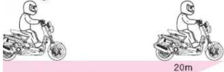
natural_image
Two identical cartoon figures riding motorcycles, one on the left and one on the right, with a pink background and '20m' label (no text or symbols on the figures themselves)then using only front brake

natural_image
Two identical line drawings of a person riding a motorcycle, one labeled 28m (no text or symbols on the figures)then using only rear brake
Learn the proper braking method to prevent accident.
natural_image
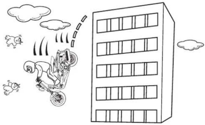
Cartoon illustration of a motorcycle flying near a multi-story building with clouds and sheep (no text or symbols)Impact increases in proportion to the speed and weight. The impact when collision to concrete wall at 50 km/h is same as one when falling from the height of 10m.
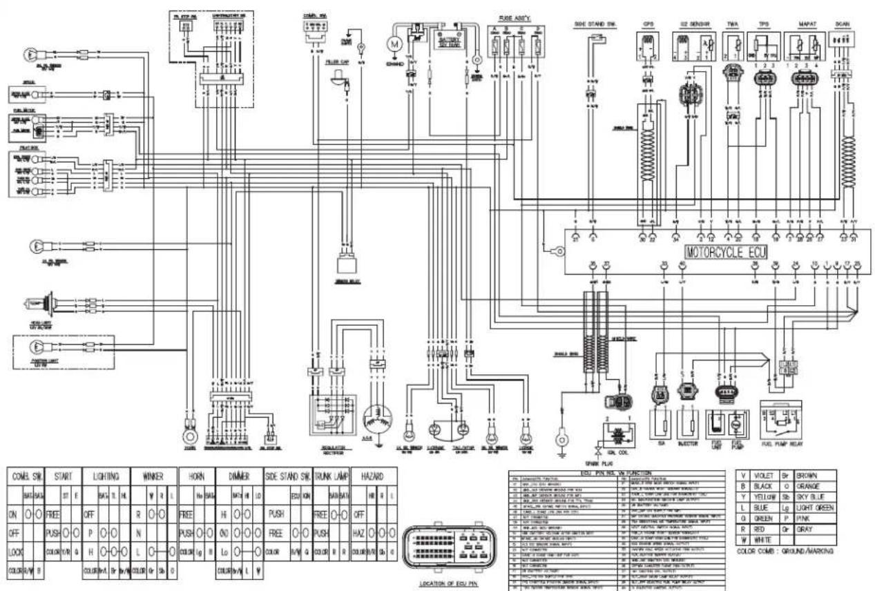
IRING DIAGRAM (EURO-2)

| COMB. SW. | START | LIGHT S/W | WINKER | HORN | DIMMER | PASSING | SIDE STAND SW. | |||||||||||||||||||||
| BAT# | BAT# | ST | E | HL | TL | C1 | RE | W | R | L | Ho | BAT# | BAT# | H | LO | BAT# | BAT# | H | E | CD | ||||||||
| ON | FREE | OFF | R | FREE | HI | FREE | FREE | |||||||||||||||||||||
| OFF | PUSH | P | N | PUSH | ON | PUSH | PUSH | |||||||||||||||||||||
| LOCK | COLOR | Y/R | O | ON | L | COLOR | Lg | B | Lo | COLOR | S | L | COLOR | 0 | B/M | |||||||||||||
| COLOR | R | B | COLOR | L/W | Ir | Y | P | COLOR | Gr | Sb | O | COLOR | Br/W | L | W | S | ||||||||||||
| V | VIOLET | Br | BROWN |
| B | BLACK | O | ORANGE |
| Y | YELLOW | Sb | SKY BLUE |
| L | BLUE | Lg | LIGHT GREEN |
| G | GREEN | P | PINK |
| R | RED | Gr | GRAY |
| W | WHITE |
COLOR COMB : GROUND/MARKING
RING DIAGRAM (EURO-3)
- ERATOR AND PASSENGER
- WARNING
- -ROAD USE
- AD THIS OWNER'S MANUAL CAREFULLY
- CAUTION
- NOTE
- CONTENTS
- SPECIFICATION
- ERATION INSTRUCTION
- SAFETY PRECAUTIONS
- OR TO STARTING VEHICLE FOR SAFE DRIVING
- OPERATION
- RRECT ATTIRE
- MODIFICATION
- ГАСНМЕНТ
- MUFFLER
- TS LOCATION
- ER READING AND USAGE
- TER
- EL METER>
- TANK CAPACITY : 7.1ℓ (EU2 : 6.8ℓ) ERVE FUEL CAPACITY : 1.2ℓ CEDOMETER>
- OMETER>
- WARNING AND INDICATOR LAMPS
- MIL
- TCH OPERATION
- IN SWITCH
- START BUTTON
- ADLIGHT
- RNING ON HEADLIGHT>
- HIGH BEAM
- LOW BEAM
- PASSING SWITCH
- JKER SWITCH
- HORN BUTTON
- IPMENT USAGE
- EERING STEM LOCK
- CKING>
- LOCKING>
- HOLE FOR A CHAIN LOCKSEAT LOCK
- STARTING THE ENGINE
- 'ER STARTING ENGINE
- OPER DRIVING METHODS
- brakes should never be denly applied and the handle s should never be suddenly ned.>
- STOPPING
- : INSPECTIONS BEFORE OPERATION
- INSPECTION OF CONCENED AREA
- AKE INSPECTION
- TIRE INSPECTION
- ACKS/DAMAGE>
- NORMAL WEAR>
- EL CHECK
- ECK>
- GINE OIL CHECK
- LIGHTS AND WINKER INSPECTION
- LB REPLACEMENT METHOD
- ADLIGHT BULB>
- REAR VIEW MIRROR
- FUEL LEAK INSPECTION
- ITENANCE
- INTENANCE SCHEDULE
- INTENANCE PRECAUTIONS
- BRAKE HOSE, PIPE LEAKAGE, DAMAGE, ASSEMBLY STATE
- ANGING ENGINE OIL
- [SPECIFIED GENUINE OIL]
- ANSMISSION OIL INSPECTION
- RECOMMENDED OIL : SAE80W-90
- E PRESSURE INSPECTION
- BATTERY INSPECTION
- FUSE REPLACEMENT
- AIR CLEANER ELEMENT INSPECTION
- BLE RUBBER PART
- SPARK PLUG
- JG GAP : 0.8\~0.9mm>
- NDARD PLUG : CR8EH-9>
- HANDLING FOR POOR STARTING
- E STAND INSPECTION
- CLEANING
- STORAGE GUIDEGENERAL CLEANING
- AME AND ENGINE NUMBER
- /ING METHOD
- IVING POSITION
- ECAUTION WHEN DRIVING
- ARTING
- OSITIONS OF TURNING
- EAN-WITH >
- TURNING METHOD
- EAN-OUT >
- ECAUTION WHEN TURNING
- EAD ANGLE ZONE >
- < DISTANCE BETWEEN THE FRONT AND REAR WHEEL TURN>
- AKING METHOD
- SIC PRINCIPLE OF BRAKE (FRICTION FORCE) RESTRAINT OF BRAKE EFFECT (INERTIA)
- AKING METHOD IMPACT WHEN COLLISION
- RING DIAGRAM (EURO-3)
Brand : DAELIM
Model : B-Bone
Category : Scooter