DC 2020 - Audio Mixer SOUNDCRAFT - Free user manual and instructions
Find the device manual for free DC 2020 SOUNDCRAFT in PDF.


| Product Type | Digital Mixing Console |
| Brand | Soundcraft |
| Model | DC 2020 |
| Channels | 20 Input Channels |
| Dimensions (W x D x H) | 550 x 400 x 150 mm |
| Weight | 8.5 kg |
| Power Supply | AC 100-240V, 50/60Hz |
| Power Consumption | 40W |
| Frequency Response | 20 Hz - 20 kHz (+0.5/-1 dB) |
| Total Harmonic Distortion | < 0.005% @ 1 kHz, +20 dBu |
| Signal-to-Noise Ratio | > 90 dB (unweighted, 22 kHz BW) |
| Max Input Level | +24 dBu (XLR) |
| Max Output Level | +24 dBu (XLR) |
| Built-in Effects | 24-bit digital effects (delay, reverb, chorus) |
| EQ | 4-band parametric on each channel |
| Interfaces | USB Audio, MIDI, Ethernet (control) |
| Output Connectors | XLR (main, monitor), 1/4" TRS (aux, insert) |
| Cleaning | Use dry cloth; avoid solvents |
| Safety | Operate in well-ventilated area; do not expose to moisture |
| Spare Parts / Repairability | Contact authorized service center |
Frequently Asked Questions - DC 2020 SOUNDCRAFT
User questions about DC 2020 SOUNDCRAFT
0 question about this device. Answer the ones you know or ask your own.
Ask a new question about this device
Download the instructions for your Audio Mixer in PDF format for free! Find your manual DC 2020 - SOUNDCRAFT and take your electronic device back in hand. On this page are published all the documents necessary for the use of your device. DC 2020 by SOUNDCRAFT.
USER MANUAL DC 2020 SOUNDCRAFT
This equipment complies with the EMC Directive 89/336/EEC
For further details contact:
Harman International Industries Ltd, Cranborne House, Cranborne Road, Potters Bar, Hertfordshire, EN6 3JN, U.K.
Tel: +44 (0) 1707 665000 Fax: +44 (0) 1707 660482
© Soundcraft Electronics Ltd. 1995
All rights reserved
Parts of the design of this product are protected by worldwide patents.
Part No. ZM0103-01
Information in this manual is subject to change without notice and does not represent a commitment on the part of the vendor. Soundcraft Electronics Ltd. shall not be liable for any loss or damage whatsoever arising from the use of information or any error contained in this manual, or through any mis-operation or fault in hardware or software contained in the product.
No part of this manual may be reproduced, stored in a retrieval system, or transmitted, in any form or by any means, electronic, electrical, mechanical, optical, chemical, including photocopying and recording, for any purpose without the express written permission of Soundcraft Electronics Ltd.
It is recommended that all maintenance and service on the product should be carried out by Soundcraft Electronics Ltd. or its authorised agents. Soundcraft Electronics Ltd. cannot accept any liability whatsoever for any loss or damage caused by service, maintenance or repair by unauthorised personnel.
Soundcraft Electronics Ltd.
Cranborne House
Cranborne Industrial Estate
Cranborne Road
Potters Bar
Hertfordshire
England
Tel: 01707 665000
Fax: 01707 660482
Table of Contents
Introduction 1.1
Introduction 1.2
Typical-Use Environment 1.3
Warranty 1.4
Installation 2.1
Dimensions 2.2
Assembling The Console Stand 2.3
Precautions and Safety Instructions 2.4
Installation 2.6
Connections 2.7
Connecting the DC2020 to a MAC or to a PC 2.9
Installing the MAC or PC Emulation Software 2.10
Patchbay EDAC Pin Identification Chart and
Pinouts 2.11
Block Diagrams 3.1
Functional Descriptions 4.1
Mono Inputs 4.3
Mono Input 4.4
Group/Stereo Input 4.11
Group/Stereo Input 4.12
Auxiliary Master 4.15
Auxiliary Master 4.16
Studio Outputs & FB Masters 4.19
Studio Outputs & Foldback Masters 4.20
Oscillator & Talkback Panel 4.23
Oscillator and Talkback Panel 4.24
Control Groups 4.27
Control Groups 4.28
Stereo Master 4.31
Stereo Master 4.32
Control-room Phones and Speakers 4.35
Control-room Phones and Speakers 4.36
Patchbay 4.39
Patchbay Fascia 4.40
Patchbay Wiring 4.41
Automation Guide 4.47
Introduction 4.49
Introduction to the Automation 4.50
Project Management 4.55
Introduction 4.56
The Automation Pages 4.61
The Automation Pages 4.62
Alphanumeric Keypad 4.64
Channel List 4.65
Channel Solo-In-Place Safe 4.66
Default Mode On Stop 4.67
Default Settings 4.68
Edit Midi Events 4.69
Glideback 4.70
Group Assignments 4.71
Meterbridge Set-up 4.72
Midi Events 4.73
Mix 4.75
Mix Information 4.77
Mix List 4.79
Monitor Solo-In-Place Safe 4.81
On Line Mix Edit Options 4.82
Presets 4.83
Project 4.89
Project Configuration 4.91
Project Utilities 4.92
Record Enable 4.93
Record Track Remap 4.94
Remap Console 4.95
Set-up 4.96
Stereo Inputs Safe 4.97
Stop Edit Options 4.98
Studio 4.99
Studio Configuration 4.100
Studio Utilities 4.101
Switch Select On Tape Stop 4.102
Tape Machine Selection 4.103
Timecode Generator 4.104
Title Configuration 4.105
Title Utilities 4.107
Track List 4.108
User 4.109
User Configuration 4.110
User Utilities 4.111
Automated Mixing 4.113
Starting The Automation 4.114
Automated Mixing 4.115
Cue Points 4.116
Automated Fader and Switch Modes 4.117
Using Control Groups 4.120
Moving the Tape 4.122
Mixing a New Title 4.123
Editing an Existing Mix 4.124
Starting a New Mix 4.125
Drop-in/Drop-out During the Original
Track-laying 4.126
Specifications 5.1
Specifications 5.2
Appendices
Notes For Machine Control for Software Release 7.00 A.1
DC2020 Error Messages B.1
DC2020 Printer Port C.1
DC2020 Diagnostics Disk D.1
Introduction
Overview
The DC2020 is an in-line studio mixing console. It is available in three sizes; 24, 32 and 40 input channels. Each of these is available with a patchbay.
The console features the following:
- Mix Automation, which controls:
4 switches and 1 fader per input channel (Aux1 ON, Aux3 ON, Channel CUT, Monitor CUT and the Monitor Fader);
Automated switches (Global mode switches) and fader on the Master Section;
Project Management functions;
Tape Machine transport functions.
- A 4-band semi-parametric EQ which is splittable and switchable between channel and monitor paths.
- Four Stereo Returns with a 2-band EQ.
- Four Stereo Groups.
- Four Automated Control Groups.
- Six Auxiliaries.
- LED Meterbridge, with a choice of meter laws plus Timecode display.
• MIDI IN/OUT/THRU.
- SMPTE IN/OUT.
- Video Sync Input
- Printer Interface.
- Serial Interface to Remote Tape Machines.
- Serial Interface to PC or MAC for Touch-screen Emulation.
- A Hard-disk Drive.
- Extended RAM for longer mixes.
• One IBM PC-format 3.5" Floppy-disk Drive.
- Touch-sensitive LCD display of Automation functions.
Typical-Use Environment
| The console is designed to be used with a multi-track tape machine or any LTC/MIDI Timecode generating device. Timecode is read by the console to provide the time base for the Mix Automation. | |
| Software | The program which runs the automation system within the console is held on the hard-disk drive. New releases may be loaded onto the hard-disk drive via the floppy drive. |
| Power Supply Unit | The DC2020 uses an APS520 Power Supply Unit. Note that this power supply has powerful cooling fans: it is therefore advisable to install it away from the control room. |
Good Housekeeping | We strongly recommend that you take regular backups of your hard disk.This is done by selecting the appropriate backup option from one of the following screens: Studio Utilities, User Utilities, Project Utilities or Title Utilities. |
| Shutting-Down The Console | |
 | It is important that you do not switch the power supply off without first shutting down the automation system correctly.This is done by selecting the Shutdown Console from one of the following screens: Studio Utilities, User Utilities, Project Utilities or Title Utilities.The Shutdown Console utility writes the contents of RAM to disk, closes all of the open disk files and then prompts you to switch the console off. |
1 Soundcraft means Soundcraft Electronics Ltd.
End User means the person who first puts the equipment into regular operation.
Dealer means the person other than Soundcraft (if any) from whom the End User purchased the Equipment, provided such a person is authorised for this purpose by Soundcraft or its accredited Distributor.
Equipment means the equipment supplied with this manual.
2 If within the period of twelve months from the date of delivery of the Equipment to the End User it shall prove defective by reason only of faulty materials and/or workmanship to such an extent that the effectiveness and/or usability thereof is materially affected the Equipment or the defective component should be returned to the Dealer or to Soundcraft and subject to the following conditions the Dealer or Soundcraft will repair or replace the defective components. Any components replaced will become the property of Soundcraft.
3 Any Equipment or component returned will be at the risk of the End User whilst in transit (both to and from the Dealer or Soundcraft) and postage must be prepaid.
4 This warranty shall only be available if:
a) the Equipment has been properly installed in accordance with instructions contained in Soundcraft's manual; and
b) the End User has notified Soundcraft or the Dealer within 14 days of the defect appearing; and
c) no persons other than authorised representatives of Soundcraft or the Dealer have effected any replacement of parts maintenance adjustments or repairs to the Equipment; and
d) the End User has used the Equipment only for such purposes as Soundcraft recommends, with only such operating supplies as meet Soundcraft's specifications and otherwise in all respects in accordance Soundcraft's recommendations.
5 Defects arising as a result of the following are not covered by this Warranty: faulty or negligent handling, chemical or electro-chemical or electrical influences, accidental damage, Acts of God, neglect, deficiency in electrical power, air-conditioning or humidity control.
-
The benefit of this Warranty may not be assigned by the End User.
-
End Users who are consumers should note their rights under this Warranty are in addition to and do not affect any other rights to which they may be entitled against the seller of the Equipment.
Installation

| CONSOLE WIDTH WEIGHT | ||||
| 24 ch | 1368.40mm | 53.87" | 72kgs | 158lbs |
| 24ch + Patchbay | 1688.00mm | 66.46" | 80kgs | 176lbs |
| 32ch | 1688.00mm | 66.46" | 80kgs | 176lbs |
| 32ch + Patchbay | 2007.60mm | 79.04" | 88kgs | 194lbs |
| 40ch | 2007.60mm | 79.04" | 88kgs | 194lbs |
| 40ch + Patchbay | 2327.20mm | 91.62" | 96kgs | 212lbs |
Assembling The Console Stand

Precautions and Safety Instructions
General Precautions
Avoid storing or using the mixing console in conditions of excessive heat or cold, or in positions where it is likely to be subject to vibration, dust or moisture. Do not use any liquids to clean the fascia of the unit: a soft dry brush is ideal. Use only water or ethyl alcohol to clean the trim and scribble strips. Other solvents may cause damage to paint or plastic parts.
Avoid using the console close to strong sources of electromagnetic radiation (e.g. video monitors, highpower electric cabling): this may cause degradation of the audio quality due to induced voltages in connecting leads and chassis. For the same reason, always site the power supply away from the unit.
Caution! In all cases, refer servicing to qualified personnel.
Handling and Transport
The console is supplied in a wooden crate. If it is necessary to move it any distance after installation it is recommended that this packing is used to protect it. Be sure to disconnect all cabling before moving. If the console is to be regularly moved we recommend that it is installed in a foamlined flightcase. At all times avoid applying excessive force to any knobs, switches or connectors.
Power Supplies & cables
Always make sure that the power supply unit (PSU) has been set to the same voltage as the mains supply
Always use the power supply and cable supplied with the mixer: the use of alternative supplies may cause damage and voids the warranty; the extension of power cables may result in malfunction of the mixing console.
Warning!
Always switch the power supply off before connecting or disconnecting the mixer power cable, removing of installing modules, and servicing. In the event of an electrical storm, or large mains voltage fluctuations, immediately switch off the PSU and unplug from the mains.
Always ensure that you use the correct PSU for your mixer. The DC2020 uses a APS500A power supply.
Signal Levels
It is important to supply the correct input levels to the console, otherwise signalto noise ratio or distortion performance may be degraded; and in extreme cases, damage to the internal circuitry may result. Likewise, on all balanced inputs avoid sources with large commonmode DC, AC or RF voltages, as these will reduce the available signal range on the inputs. Note that 0dBu = 0.775V RMS.
The microphone inputs are designed for use with balanced low impedance (150 or 200 ohms) microphones.
Caution!
DO NOT use unbalanced microphones or battery powered condenser microphones without isolating the +48V phantom power: degraded performance or damage to the microphone may result.
The sensitivity of the XLR inputs is variable from -2dBu to -70dBu and +10dBu to -20dBu in two ranges (for +4dBu at the Mix outputs). The maximum input level is +28dBu.
The Hi-Z inputs have a sensitivity variable between +10dBu and -20dBu. The maximum input level is +30dBu.
The main outputs of the console (stereo mix, groups, wedge and mix and group insert sends) are balanced at a nominal level of +4dBu, with a maximum output level of +26dBu.
The input insert sends and direct outputs are ground compensated at a nominal level of -2dBu, with a maximum output level of +20dBu.
All external inputs and mix and group insert returns have a nominal level of +4dBu, and a maximum input level of +26dBu.
Input insert returns have a nominal level of -2dBu, and a maximum input level of +20dBu.
Installation
| The DC2020 is designed for reliability and high performance, and is built to the highest standards. Whilst great care has been taken to ensure that installations are made as troublefree as possible, care taken at this stage, followed by correct setting up will be rewarded by a long life and reliable operation. | |
| Wiring Considerations | A For optimum performance it is essential for the earthing system to be clean and noisefree, as all signals are referenced to this earth. A central point should be decided on for the main earth point, and all earths should be ’star-fed’ from this point. It is recommended that an individual earth wire be run from each electrical outlet, back to the system star point to provide a safety earth reference for each piece of equipment.B Install separate mains outlets for the audio equipment, and feed these independently from any other equipment.C Avoid locating mains distribution boxes near audio equipment, especially tape recorders, which are very sensitive to electromagnetic fields.D Where possible ensure that all audio cable screens and signal earths are connected to ground only at their source. |
| Power Supply (APS520) | Always ensure that you use the correct PSU for your mixer. The DC2020 uses a APS520 power supply. |
| Warning! | Before switching on your DC2020 console, check that the mains voltage selectors on the power supply unit is set to the correct mains voltage for your area, and that the fuse is of the correct rating and type. This is clearly marked on the case of the power supply. Do not replace the fuse with any other type, as this could become a safety hazard and will void the warranty. |
Wiring conventions
The DC2020 uses two different types of audio connector: 3-pin XLR and/4" 3-pole jacks. The latter are used in several configurations, as shown below (note that the patchbay versions have no 1/4" jack sockets except for the SMPTE In and Out connections). The DC2020 also uses DIN, D-type and BNC connectors: these are shown on the next page.
MICROPHONE INPUTS

1/4" 'A' Gauge Stereo Jack Plug used as balanced input: Line Inputs, Stereo Inputs, Tape Inputs, 2-Trk Inputs, Group Inserts and SMPTE Timecode In

1/4" 'A' Gauge Stereo Jack Plug used as Insert Send/Return Point: Mono Input Insert, Mix Insert
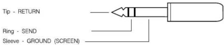
1/4" 'A' Gauge Stereo Jack Plug used as ground compensated output: Tape Sends, Group Outputs, Aux Outputs, Studio Phones, Studio Speakers, FB Outputs, Mix Outputs, Control-room Outputs, Alt Outputs and SMPTE Timecode Out

1/4" 'A' Gauge Stereo Jack Plug used as stereo output: Headphones

DIN Connectors
The MIDI IN signal is buffered by an opto-isolator.

MIDI THRU

MIDI OUT

D-Type Connectors
Ports 1, 2 and 4 are not used.

PORT 3 Female
Port 3 conforms to EIA RS-422A. It is used to connect to Sony 9-pin connectors, see Appendix A for details.

PORT 5
Male
Port 5 connects to a MAC or a PC for remote emulation of the Touch Screen. See the next page for details of the cable required.

PARALLEL Female
The Parallel Port is an industry-standard Centronics interface. See Appendix C for more details.
BNC Connector
Video Sync Input

Centre Pin Standard Composite Video Signal (1v pk-pk 75ohms) Body Ground
Connecting the DC2020 to a MAC or to a PC
You may connect the DC2020 to either a MAC or a PC to provide touch-screen emulation. In either case you will need to make or obtain a suitable connecting lead. The connections required are shown in the diagrams below.
DC2020 To MAC Connection
Port 5 on DC2020
9-way Male D-type
Macintosh Modem Port
8-pin MiniDIN

DC2020 To PC Connection
Port 5 on DC2020
9-way Male D-type
Serial Port on PC
9-way Male D-type

Installing the MAC or PC Emulation Software
Software is provided with the DC2020 which allows the touch screen of the console to be used via a computer interface. Such software is available for either the PC or the Macintosh. The software is an emulation of the touch screen but allows use of a mouse (or other pointing device) and input from the computer keyboard.
Installing the DC2020 Emulation Software
DC for Macintosh
- From the File Menu select new to create a new folder on your hard disk.
- Click on the folder label and change the name of the folder to DC2020.
- Insert the floppy disk RX3023 into the disk drive.
- Double click the disk icon.
- Drag the DC2020 icon from the disk window to the DC2020 folder on the hard disk.
- In order to run the emulation software, double click the DC2020 icon.
On powering up the DC2020 console, an image of the DC2020 touch screen will appear on the Macintosh screen.
DC for Windows.
- Run Microsoft Windows.
- Run File Manager.
- Insert the floppy disk RX3026 into drive A.
- Using File Manager copy dcfw.exe from drive A to your hard disk.
- While in File Manager drag the dcfw.exe filename into a window on your desktop.
- In the Program Manager select File Properties...
i. type DC2020 display in the description box
ii. click OK
-
To run the emulation software double click the DC for Windows icon
-
Once the DC2020 emulation is running, choose Select Port... from the Settings pull down menu. Select the PC port to which your PC-to-Console cable is connected e.g. port 1.
IMPORTANT:
It is important to understand that the Windows / Macintosh interface is an emulation of the DC2020 touch sensitive screen. Therefore, the location of a mouse click on the computer screen is translated into a press on one or more cells of the touch sensitive screen. Consequently a touch pad in close proximity to the mouse click may respond, even though the mouse pointer is not strictly within the box. This may run contrary to expectations if one is familiar with Windows or Macintosh applications.
Patchbay EDAC Pin Identification Chart and Pinouts

TAPE TRACKS 1-8
A....TRET+6
B . . . . . . . . . . . . . . . . . TRET-6
C GND
D....TSND+7
E....TSND-6
F....GND
H . . . . . . . . . . . . . . . . . . . . GND
J GND
K....TSND-7
L....TSND+6
M. . . . . . . . . . . . . . . . . . . GND
N . . . . . . . . . . . . . . . . . TRET-7
P....TRET+7
R....TRET+5
S....TRET-5
T....GND
U....GND
V....TSND+8
W....TSND-5
X....GND
Y GND
Z. TSND-8
a . . . . . . . . . . . . . . TSND+5
b GND
c....TRET-8
d....TRET+8
e . . . . . . . . . . . . . . . . . GND
f....GND
h. . . . . . . . . . . . . . . . . . . . GND
j....GND
k....TRET+4
- TRET-4
m....GND
n. TSND+1
p....TSND-4
r....GND
s. GND
t . . . . . . . . . . . . . . . TSND-1
u....TSND+4
V. . . . . . . . . . . . . . . . . . . . . GND
W . . . . . . . . . . . . . . . . . . GND
x....TRET-1
y....TRET+1
Z. TRET+3
AA . . . . . . . . . . . . . . . TRET-3
BB GND
CC....TSND+2
DD....TSND-3
EE....GND
FF....GND
HH GND
JJ TSND-2
KK....TSND+3
LL. . . . . . . . . . . . . . . . . . . GND
MM....TRET-2
NN . . . . . . . . . . . . . . . TRET+2
TAPE TRACKS 9-16
A . . . . . . . . . . . . . . . . . . TRET+14
B....TRET-14
C GND
D....TSND+15
E....TSND-14
F....GND
H. . . . . . . . . . . . . . . . . . . GND
J....GND
K....TSND-15
L....TSND+14
M....GND
N....TRET-15
P....TRET+15
R....TRET+13
S....TRET-13
T....GND
U GND
V....TSND+16
W....TSND-13
X....GND
Y GND
Z....TSND-16
a. TSND+13
b. GND
c....TRET-16
d....TRET+16
e . . . . . . . . . . . . . . . . . . GND
f....GND
h. . . . . . . . . . . . . . . . . . GND
j GND
k....TRET+12
- TRET-12
m . . . . . . . . . . . . . . . . . . GND
n. TSND+9
p....TSND-12
r....GND
S. GND
t....TSND-9
u....TSND+12
V. . . . . . . . . . . . . . . . . . . . . . . GND
W GND
x....TRET-9
y....TRET+9
Z....TRET+11
AA....TRET-11
BB GND
CC . . . . . . . . . . . . . TSND+10
DD . . . . . . . . . . . . . . TSND-11
EE....GND
FF GND
HH....GND
JJ . . . . . . . . . . . . . . . TSND-10
KK . . . . . . . . . . . . TSND+11
LL....GND
MM....TRET-10
NN....TRET+10
TAPE TRACKS 17-24
A . . . . . . . . . . . . . . . . . . TRET+22
B . . . . . . . . . . . . . . . . . TRET-22
C GND
D....TSND+23
E....TSND-22
F....GND
H. . . . . . . . . . . . . . . . . . . GND
J....GND
K....TSND-23
L....TSND+22
M....GND
N....TRET-23
P....TRET+23
R....TRET+21
S....TRET-21
T....GND
U GND
V....TSND+24
W....TSND-21
X....GND
Y GND
Z. TSND-24
a. TSND+21
b. GND
c....TRET-24
d....TRET+24
e . . . . . . . . . . . . . . . . . GND
f....GND
h. . . . . . . . . . . . . . . . . . GND
j GND
k....TRET+20
- TRET-20
m . . . . . . . . . . . . . . . . . . . GND
n....TSND+17
p....TSND-20
r....GND
S. GND
t....TSND-17
u....TSND+20
V. . . . . . . . . . . . . . . . . . . . . . . GND
W GND
x....TRET-17
y....TRET+17
z....TRET+19
AA....TRET-19
BB GND
CC . . . . . . . . . . . . . TSND+18
DD....TSND-19
![graph TD A["GP BUS ODD"] --> B["SUM AMP ODD"] B --> C["INSERT"] C --> D["CUT"] D --> E["GROUP FADER"] E --> F["GROUP OUT ODD GNDCOMP"] F --> G["MIX"] G --> H["MIX BUS L & R"] I["GP BUS EVEN"] --> J["SUM AMP EVEN"] J --> K["INSERT"] K --> L["CUT"] L --> M["GROUP OUT EVEN GNDCOMP"] M --> N["GROUP METE…](/content/2026/06/1370664/images/24144bb990ef8a06b62725575297d4fa7b02f76ab3aee962340acda5cb26eadd.jpg)
Aux Master
![graph TD subgraph Top_Layer A["AFL EN"] --> B["APL SWITCH"] B --> C["AUX2 OUTPUT (GNDCOMP)"] C --> D["AMPLIFIER"] D --> E["AUX ELECT SWITCH"] E --> F["AUX1 OUTPUT (PFL BUS)"] F --> G["AFL EN"] G --> H["AFL SWITCH"] H --> I["AUX4 OUTPUT (GNDCOMP)"] I --> J["AMPLIFIER"] end subgraph Bottom_Layer K["AF…](/content/2026/06/1370664/images/c68dc81641449b2d626e2e07e36e18703a75d64f7679c765f728950a85458670.jpg)
3.4 DC2020 Block Diagrams
Studio, Foldback and Oscillator/Talkback
![graph LR A["MONITOR SELECT LEFT"] --> B["FOLBACK/CRM SUB MIXER"] C["MONITOR SELECT RIGHT"] --> D["FOLBACK/CRM SUB MIXER"] B --> E["AMBI"] D --> E E --> F["AFL"] F --> G["AFL SWITCH"] G --> H["TALK BACK TO STU PHONES"] H --> I["AMPLIFIER"] I --> J["OUTPUT TO STUDIO PHONES LEFT (GNDCOMP)"] J --> K["TA…](/content/2026/06/1370664/images/a6ba0f9aea9f8fca6ea93a6b468322f3784b168a4ec0decdd6504f79dd7b3b43.jpg)
![graph LR subgraph FOLDBACK_MASTERS A["FOLDBACK BUSSES"] --> B["FOLDBACK 1 SUMMING AMPLIFIER"] C["FOLDBACK BUSSES"] --> D["FOLDBACK 2 SUMMING AMPLIFIER"] E["FROM INPUT SENS"] --> B F["FOLDBACK BUSSES"] --> G["FOLDBACK BUSSES"] H["FOLDBACK BUSSES"] --> I["FOLDBACK BUSSES"] J["FOLDBACK BUSSES"] --> K["…](/content/2026/06/1370664/images/1d92711be78b0c384f4820da04598232520168de1c2779417ee42bf139c73014.jpg)
Mix and Control Room Monitor
![graph TD subgraph STEREO_MIX_SECTION A["TALKBACK TO MIX"] --> B["SUMMING AMPLIFIER"] C["MONL BUS"] --> D["SUMMING AMPLIFIER"] E["INSERT SEND/RETURN (UNBAL)"] --> F["VCA"] G["CONTROL FROM CADENCE"] --> H["AMPLIFIER"] I["TALBACK TO MIX"] --> J["SUMMING AMPLIFIER"] K["MONR BUS"] --> L["SUMMING AMPLIFIE…](/content/2026/06/1370664/images/2028002de1c7f45e007076cbcf41c2f1de30c6754c23e7ab7f9336d87a0ddd83.jpg)
3.6 DC2020 Block Diagrams
Functional Descriptions
Mono Inputs
Mono Input

Input Control Section
1 If the +48V switch is depressed then +48V phantom power is supplied to the rear-panel Mic XLR socket
2 When the LINE switch is released the input to the channel is via the Mic XLR socket; when the LINE switch is depressed the input is via the 1/4"Line socket
The input sensitivity is -40dBu to +10dBu for Line input and -60dBu to -10 dBu for Mic input.
3 The gain of the input amplifier is controlled by the INPUT Gain pot., the gain range is +10db to +60dB.
4 The (Phase) button reverses the phase of the input signal.
5 The input amplifier is followed by a 100Hz high-pass filter. This is switched in or out of the circuit by the 100Hz switch: when the switch is depressed the filter is in circuit.
Tape Return
The electronically balanced tape return is switchable, via a switch which is accessible on the underside of the console, between nominal levels of +4dBu and -10dBV.
6 The Tape Return Trim control has a gain range of +/-10dB.
7 The Monitor Source switch (MON SRC) selects either the Tape Return or the Tape Send as the monitor source. When the switch is released the Tape Return is the monitor source.
8 The Tape Source switch (TAPE SRC) selects either the Channel post-fade signal direct (DIR) or the Group Return signal as the Tape Send source. When the switch is released the direct signal is used as the Tape Send source. When the switch is depressed the Group Return is the source. The Groups Returns feed the Channels as follows:
Group 1 - Channels 1,9,17,25,33.
Group 2 - Channels 2,10,18,26,34.
Group 3 - Channels 3,11,19,27,35.
Group 4 - Channels 4,12,20,28,36.
Group 5 - Channels 5,13,21,29,37.
Group 6 - Channels 6,14,22,30,38.
Group 7 - Channels 7,15,23,31,39.
Group 8 - Channels 8,16,24,32,40.
Note: Channels 25-40 may not be present on your console.
EQ
The EQ is split into two parts. The first part is the HF/LF EQ, this consists of two equalisers which may be independently configured as shelving or bell-response filters.
9 The HF Bell/Shelf switch configures the HF EQ. The bell-response Q factor is 1.5.
10 The HF Cut/Boost control provides a cut and boost of +/-15dB.
11 The HF Frequency control, which is calibrated from 500Hz to 16kHz, sets the shelving frequency cut-off point (-3dB) or the peak frequency, depending upon whether shelving or bell response has been selected.
12 The LF Bell/Shelf switch configures the LF EQ. The bell-response Q factor is 1.3.
13 The LF Cut/Boost control provides a cut and boost of +/-15dB.
14 The LF Frequency control, which is calibrated from 50Hz to 1.6kHz, sets the shelving frequency cut-off point (-3dB) or the peak frequency, depending upon whether shelving or bell response has been selected.
15 The HF/LF EQ can be switched into the Channel signal path or the Monitor signal path via the MON switch: when the switch is depressed the HF/LF EQ is placed in the Monitor signal path.
The second part is the HI MID/LO MID EQ. This consists of two bell-response equalisers. Each of these may be set one of two Q-factors.
16 The Hi Mid Lo Q/Hi Q switch switches the Q factor between 1.2 and 2.0.
17 The Hi Mid Cut/Boost control provides a cut and boost of +/-15dB.
18 The Hi Mid Frequency control, which is calibrated from 500Hz to 16kHz, sets the peak frequency.
19 The Lo Mid Lo Q/Hi Q switch switches the Q factor between 1.2 and 2.0.
20 The Lo Mid Cut/Boost control provides a cut and boost of +/-15dB.
21 The Lo Mid Frequency control, which is calibrated from 50Hz to 1.6kHz, sets the peak frequency.
22 The HI MID/LO MID EQ can be switched into the Channel signal path or the Monitor signal path via the MON switch: when the switch is depressed the HI MID/LO MID EQ is placed in the Monitor signal path.
23 The EQ IN switch will, when depressed, switch both EQ sections into their selected paths. When the switch is released neither EQ sections are in their respective paths. This switch does not affect the Insert Point.


Note: the Insert Point (via rearcon panel, or patchbay if fitted) is placed after the HF/LF EQ and is switched, with this EQ section, between the Channel path and the Monitor path, via the HF/LF EQ's EQ TO MON switch.
Auxiliary Controls
24 The AUX1 Level control is permanently connected to the Monitor path and is post the Monitor Cut and the Monitor Fader.
25 The Aux1 ON switch is a soft switch, i.e. this switch provides an input to the Automation. The Automation, in turn, controls the ON LED (green), the Arm LED (amber) and switches the signal from the Aux1 level control to the Aux1 bus.
The green ON LED glows when the channel's Aux1 signal is being fed to the Aux1 bus.
26 The AUX2 Level control is permanently connected to the Monitor path and is post the Monitor Cut and the Monitor Fader.
27 The AUX3 and AUX4 level controls are switchable (together) between the Monitor and the Channel paths. Both Aux3 and Aux4 feeds are connected to the Channel path when the CHAN switch is depressed.
For either path, the Aux3 and Aux4 feeds are taken post the Cut and the Fader of the relevant path.
28 The Aux3 ON switch is a soft switch, i.e. this switch provides an input to the Automation. The Automation, in turn, controls the ON LED (green), the Arm LED (amber) and switches the signal from the Aux3 level control to the Aux3 bus.
The green ON LED glows when the channel's Aux3 signal is being fed to the Aux3 bus.
Foldback
29 The Foldback 1 Level Control, marked as FB1/L CH/MON, sends two signals to the Foldback Masters & Studio Outputs PCB, as follows:
1 The Channel pre-fade or post-fade signal (depending upon the position of the POST switch, see below).
2 The Monitor pre-fade or post-fade signal (depending upon the position of the POST switch, see below).
The Foldback 1 Control may therefore be used for the Channel path signals or the Monitor Path signals. Its use is controlled by the CH/MON switch which is located on the Foldback Masters & Studio Outputs panel (see the Foldback Masters & Studio Outputs section for more details).
30 The Foldback 2 Level Control, marked as FB2/R MON, sends the Monitor pre-fade or post-fade signal (depending upon the position of the POST switch, see below) to the Foldback Masters & Studio Outputs PCB.
Note. The FB1 and FB2 signals may be used as the Left and Right channels of a stereo Foldback signal. This feature is also controlled by the Foldback Masters & Studio Outputs panel, via a switch labelled STEREO (see the Foldback Masters & Studio Outputs chapter for more details).

31 When the POST switch is depressed, both the FB1 and FB2 paths are fed post-fade; when the POST switch is released the signals are pre-fade.
Pan Control
32 The MON PAN control positions the Monitor signal within the stereo image carried by the MONL and MONR buses. These buses connect with the Mix Left & Right board where they are summed with signals carried by the MIXL and MIXR buses, and also summed with Talkback signals (see the Stereo Master chapter for more details).
33 The CHAN PAN control positions the Channel post-fade signal within a stereo image. This stereo image may be connected to the MIXL and MIXR buses, and also to the Group buses (1-8) by the use of the Routing switches (see Routing section below).
Routing
34 Normally the post-fade, post-pan Channel signal is sent to the routing matrix. This matrix is controlled by the switches marked, 1-2, 3-4, 5-6 and 7-8. When, for example, the switch marked, 1-2 is depressed, the post-fade, post-pan Channel signal is fed onto the Group 1 bus and the Group 2 bus. The Group 1 bus carries the Left image from the Channel Pan control, whilst the Group 2 bus carries the Right image from the Channel Pan control. Similarly for the remaining 3 matrix switches, the odd numbered Groups carry the Left image and the even numbered Groups carry the Right image.
The Group buses may be used to route the signal from one input channel to the tape send of a different channel.
35 The stereo image may also be connected to the MIXL and MIXR buses, this is done by depressing the MIX switch.
36 When the BOUNCE switch is depressed, the routing matrix is disconnected from the Channel path and is, instead, connected to the Monitor path. This allows the Group buses to be used for track bouncing.
Channel Path
37 The non-motorised Channel Fader feeds the CHAN PAN control and also normally feeds the Tape Send. It may also be switched to feed Aux3 & Aux4, and FB1
38 A multi-point peak detector illuminates the CHAN PEAK LED when less than 6dB of headroom remains at two critical places in the signal path: the Input preamp and the pre-fade connection to the Channel Fader.
39 The Channel SOLO switch is a soft switch, i.e. this switch provides an input to the Automation. The Automation, in turn, passes the Channel signal onto the PFL bus and also switches the input of the Control-room/Headphones (CRM/PH) circuit from its selected input to the PFL bus.
The Automation also indicates, by switching on the associated SOLO LED, that the Solo is active on the Channel.
The Automation gives the Solo switch a toggle action: note that the switch itself does not physically latch.

40 The Channel CUT switch is a soft switch, i.e. this switch provides an input to the Automation. The Automation, in turn, controls the Cut circuit and also the Channel CUT and Arm LEDs
41 The REC LED indicates when the tape machine is in record mode for the track which is connected to this channel.
Monitor Path
42 The motorised Monitor Fader feeds the MON PAN control, it also feeds the Aux1 and Aux2 Level controls and normally feeds the Aux3 and Aux4 Level controls. It may also be switched to feed the FB1MON and FB2 buses.
43 A multi-point peak detector illuminates the MON PEAK LED when less than 6dB of headroom remains at two critical places in the signal path: the Monitor Source switch and the pre-fade connection to the Monitor Fader.
44 The Monitor SOLO switch is a soft switch, i.e. this switch provides an input to the Automation. The Automation, in turn, passes the Monitor signal onto the PFL bus and also switches the input of the Control-room/Headphones circuit from its selected input to the PFL bus.
The Automation also indicates, by switching on the associated SOLO LED, that the Solo is active on the Monitor.
The Automation gives the Solo switch a toggle action: note that the switch itself does not physically latch.
45 The Monitor CUT switch is a soft switch, i.e. this switch provides an input to the Automation. The Automation, in turn, controls the Cut circuit and also the Monitor CUT and Arm LEDs
46 The SEL switch is a soft switch, i.e. this switch provides an input to the Automation. This switch has three functions.
Firstly, it is used to arm the Aux1, Aux3, Channel Cut and Monitor Cut switches. To Arm one of these switches, you press and hold the SEL switch and then press the CUT or Aux ON switch in question, then release both switches.
Secondly, it is used in conjunction with the Group Assignments pag. This allows you to assign channels to Control Groups, see page 4.71.
Finally, if the RECORD ENABLE or PREVIEW modes are selected (via the control panel keyboard) the SEL button may be used to Record Enable the tape track in question. The REC LED indicates when this has happened.
Automated Fader and Switch Modes
Each Automated Fader and Switches can be in one of four modes, which are as follows:
Manual.. The Fader or Switch operates normally as if it were not automated.
Read. Changes to the Fader or Switches which have previously been recorded against the Timecode are played back, i.e. the changes are read from the Automation.
Armed. This mode is the same as Read mode until you make a change, at which point the change(s) are written into the Mix Data.

Write. If the Fader is moved or a Switch is pressed this is written into the Mix Data, creating a new Mix, or writing over any previous Mix data.
47 The mode of a Fader or Switch is changed by pressing the appropriate mode switch, labelled SW for Switches and FDR for the Fader. Pressing the Mode switch causes the mode to be cycled through in the following sequence: Manual, Read, Armed and Write. Note that Manual Mode is not available whilst the Tape is running with Mix on.
48 The WR (Write) and RD (Read) LEDs indicate which mode the Fader and Switches are currently in. There are separate LEDs on each channel for Fader and Switches. The modes are indicated as follows:
RD WR
Manual: OFF OFF
Read: ON OFF
Armed: ON ON
Write: OFF ON
49 The Control Group Assigned LEDs (CNTR GRP ASN) indicate which Control Group, if any, each Input Channel is assigned to.
The Solo System
The Solo System works in two ways.
Solo
In Solo mode (the SIP LED on the Master Panel will be off) the Solo switches on both the Channel and Monitor sections behave as Pre-fade Listens, i.e. they feed the PFL signal to the Headphones./Control Room Output.
Solo In Place
In Solo-In-Place mode (the SIP LED on the Master Panel will be on) the Solo switches on both the Channel and Monitor sections will mute all other Channel or Monitor sections respectively.
Any of the Channels or Monitors may be Solo-In-Place protected (safed) so that they are not muted by other solo switches. This is done via the Monitor SIP Safe and Channel SIP Safe pages.
Meters
The Meter may be used to monitor the Channel (send) or the Monitor (return) section. The meters are switchable in groups of eight inputs. They are switched via the Meterbridge Set-up page. The current setting is indicated by the SEND and RETURN LEDs on the overbridge.
Rear Connector Panel

Microphone Input - Female XLR
Pin 1 Screen
Pin 2 Hot (in phase signal)
Pin 3 Cold (out of phase signal
The Patchbay version does not have the following connectors on the Input Rear Connector Panel: see the Patchbay section of this chapter, and the EDAC connector pin lists in chapter2, for details.
Line Input - 3-pole Jack
Tip Hot (in phase signal)
Ring Cold (out of phase signal)
Sleeve Ground
Insert
Tip Return
Ring Send
Sleeve Ground
Tape Return
Tip Hot (in phase signal)
Ring Cold (out of phase signal)
Sleeve Ground
Tape Send
Tip Hot (in phase signal)
Ring Cold (out of phase signal)
Sleeve Ground
Group/Stereo Input
Group/Stereo Input

Stereo Input
1 The -10 switch changes the nominal input level from +4dBu, when the switch is released, to -10dBV, when the switch is depressed.
EQ
2 The stereo 2-band shelving EQ has a +/-15dB cut and boost at 3kHz, which is controlled by the HF control, and a +/-15dB cut and boost at 150Hz, which is controlled by the LF control.
Routing
3 The output of the EQ section is normally fed to the Foldback level controls, marked FB1/L and FB2/R. The FB1/L control sends the Left stereo signal to the FBL bus and also a mono (L+R) signal to the FB1S bus. The FB2/R control sends the Right stereo signal to the FBR bus and also a mono (L+R) to the FB2S bus. These buses are connected to the Foldback Master & Studio Outputs panel.
4 The output of the EQ section is also fed to the Rotary FADER. The Fader has a max. gain of +10dB. It is advisable to turn this fader fully off (anti-clockwise) if the Stereo Input in question is not being used.
5 The Fader feeds the BALance control, which adjusts the relative levels of the Left and Right stereo image.
6 The output of the Balance control normally feeds the MIXL and MIXR buses, via the MIX switch; the output of the Balance control is switched over to a pair of Group buses when the MIX switch is depressed: the Group buses are identified on the panel legend, under the word, 'MIX'.
7 The Foldback level controls are fed post-fade when the POST switch is depressed.
8 The SOLO switch is a soft switch, i.e. this switch provides an input to the Automation. The Automation, in turn, controls the PFL circuit, which switches a mono (L+R) signal onto the PFL bus. The adjacent LED illuminates when the PFL circuit is active on any particular Stereo Input panel.
The Automation also activates the PFL circuit in the Control-room Phones/Speakers Panel: this feeds the Signal from the Stereo Input to the Control-room Phones/Speakers.
9 The CUT switch is a soft switch, i.e. this switch provides an input to the Automation. The Automation, in turn, controls the Cut circuit, which is post-fade.
GROUP
The 8 Group buses are processed in pairs. There are, therefore, four Group panels. The pair of Groups which each panel controls is marked on the panel.
The Group buses have two functions. The first is to allow you to route a signal from an Input Channel to a different numbered Tape send. The second is to allow track
bouncing.
Only one of the pair of signals is considered here.
The summed Group signal is passed through an unbalanced Insert point on the rear connector panel.
10 The Insert-point Return signal is fed to the Fader, which provides a gain of +10dB at the top of its travel.
11 The Insert-point Return signal is also fed to an electronic PFL switch. The input to this switch is the sum of both of the Group pair signals. The PFL switch is controlled by the Automation. The Automation reads the state of the SOLO switch to decide when to activate the electronic PFL switch. When the PFL is active, the LED adjacent to the SOLO switch is illuminated. The PFL signal is sent to the Control-room Phones/Speakers.
12 The post-fade signal is fed to an electronic cut switch. This switch is controlled by the Automation in response to the soft CUT switch. The adjacent LED illuminated when the CUT is active.
The post-cut signal is fed to its appropriate Group Return bus. The eight Group Return buses in the console facilitate the connection of any Input Channel to any Tape Send, and they are also used when track bouncing.
13 The post-cut signal is also fed, via the MIX switch, to the MIXL bus (odd-numbered Groups) or the MIXR bus (even-numbered Groups); these buses are the Stereo Master Mix buses.
The post-cut signal is also fed to an output socket on the rearcon panel.
Meters
The Metering consists of twin 16-LED bargraph meters. They may be connected to the pre-fade section of the Stereo Inputs or to the post-fade, post-cut section of the Groups. The switching is under the control of the Automation: they are switched via the Meterbridge Set-up page. The current setting is indicated by the STE and GRP LEDs on the overbridge.
Rear Connector Panel (Non-Patchbay Only)
Stereo Input
The stereo inputs are electronically balanced. The left input is normalled to the right input on the rear panel Jack sockets: if only a mono signal is available it is automatically routed to both Left and Right signal paths. Plugging a Jack plug into the Right socket disconnects the normalling.
Tip Hot (in phase signal)
Ring Cold (out of phase signal)
Sleeve Ground
Groups
Group Inserts
Tip Return
Ring Send
Sleeve Ground
Group Outputs - 3-pole Jack
The Group outputs are ground compensated. This provides a very effective way of optimising noise immunity, without the complexity of balanced outputs. Ground compensated outputs cancel the effects of variation in ground potential between the mixer and other equipment which would otherwise show up as hum.
If the output is driving an amplifier that has an unbalanced input, connect the -ive (cold) signal to the ground at the destination, not at the output of the console.
Tip Hot (in phase signal)
Ring Cold (ground sense)
Sleeve Ground

4.14 DC2020 Group/Stereo Input
Auxiliary Master
Auxiliary Master

There are four auxiliary buses. Each Input Module is able to put signals on each of the four Aux buses. Aux1 & Aux2 are only fed from the Monitor path, post-fade. Aux3 & Aux4 may be fed from The Channel path or the Monitor path, both post-fade.
Auxiliary 1
1 The signal level from the Aux1 summing amp is controlled by the AUX1 pot.
2 The AFL switch causes the post-pot, post-cut signal to be sent to the Control-room PFL/AFL system.
3 The CUT switch is a soft switch, i.e. this switch provides an input to the Automation. The Automation, in turn, controls the electronic Cut circuit, which is post-pot. The Automation also controls the adjacent CUT and ARM LEDS (red and amber respectively).
Auxiliary 2
4 The signal level from the Aux2 summing amp is controlled by the AUX2 pot.
5 The AFL switch causes the post-pot, post-cut signal to be sent to the Control-room PFL/AFL system.
6 The CUT switch is a soft switch, i.e. this switch provides an input to the Automation. The Automation, in turn, controls the electronic Cut circuit, which is post-pot. The Automation also controls the adjacent CUT and ARM LEDS (red and amber respectively).
Auxiliary 3
7 The signal level from the Aux3 summing amp is controlled by the AUX3 pot.
8 The AFL switch causes the post-pot, post-cut signal to be sent to the Control-room PFL/AFL system.
9 The CUT switch is a soft switch, i.e. this switch provides an input to the Automation. The Automation, in turn, controls the electronic Cut circuit, which is post-pot. The Automation also controls the adjacent CUT and ARM LEDS (red and amber respectively).
10 The AUX3 TO AUX1 switch, connects the Aux3 post-pot, post-cut signal to the Aux1 Master signal path, at a point which is post the Aux1 Cut circuit.
Auxiliary 4
11 The signal level from the Aux4 summing amp is controlled by the AUX4 pot.
12 The AFL switch causes the post-pot, post-cut signal to be sent to the Control-room PFL/AFL system.
13 The CUT switch is a soft switch, i.e. this switch provides an input to the Automation. The Automation, in turn, controls the electronic Cut circuit, which is post-pot. The Automation also controls the adjacent CUT and Arm LEDs (red and amber respectively).
14 The AUX4 TO AUX2 switch, connects the Aux4 post-pot, post-cut signal to the Aux2 Master signal path, at a point which is post the Aux2 Cut circuit.
Rear Connector Panel (Non-Patchbay Only)
Aux OUT 1 to AUX OUT 4 - 3-pole Jack
The Aux outputs are ground compensated. This provides a very effective way of optimising noise immunity, without the complexity of balanced outputs. Ground compensated outputs cancel the effects of variation in ground potential between the mixer and other equipment which would otherwise show up as hum.
If the output is driving an amplifier that has an unbalanced input, connect the -ive (cold) signal to the ground at the destination, not at the output of the console.
The connections are:
Tip Hot (in phase signal)
Ring Cold (ground sense)
Sleeve Ground

Studio Outputs & FB Masters
Studio Outputs & Foldback Masters

Studio Outputs
1 The signal level available at the Studio Speakers Output jacks on the rearcon panel is controlled by the C/RM TO STUDIO SPKRS pot. The input to this control is taken from the source selector switches on the Control-room Speakers/Phones Panel.
When the Talkback-to-Speakers signal (from the Talkback Panel) is present, the normal signal is dimmed and the Talkback signal is superimposed. The level of the Talkback signal is not affected by the setting of the C/RM TO STUDIO SPKRS control, it is set by the GAIN control on the TALKBACK Panel.
2 The signal level available at the Studio Headphones Output jacks on the rearcon panel is controlled by the C/RM TO PHNS pot. The input to this control is taken from the source selector switches on the Control-room Speakers/Phones Panel.
3 The FB1 switch adds in the Foldback 1 post-fade signal to the Studio Phones post-pot signal (both Left and Right signals of the Headphone stereo image).
4 Similarly, the FB2 switch adds in the Foldback 2 signal to the post-pot signal.
Both of these switches, FB1 and FB2, may be depressed at the same time. If, however the STEREO switch on the Foldback panel is depressed then the FB1 signal is only sent to the Left channel, whilst the FB2 signal is only sent to the Right channel.
5 These signals are then passed through the STUDIO PHNS level control.
When the Talkback-to-Phones signal (from the Talkback Panel) is present, the normal signal is dimmed and the Talkback signal is superimposed. The level of the Talkback signal is not affected by the setting of the STUDIO PHNS control, it is set by the GAIN control on the TALKBACK Panel.
6 The AFL switch sends a mono (L+R) signal to the PFL/AFL circuit of the Control-room Monitor. Its associated LED indicates when the switch is depressed.
Foldback Masters
The Foldback system has 2 channels: FB1 and FB2. These are controlled by the section described below.
The Foldback Master section receives inputs from two Module types: the Input Modules and the Stereo Input Modules.
Signals from Input Modules
7 The FB1 signal is switchable between the Channel and the Monitor path. The switching is done by the CH/MON switch. The level of the FB1 signal from each Input Module is controlled by the FB1/L CH/MON pot on each Input Module.
The FB2 signal is always connected to the Monitor path, its level from each Input Module is controlled by the FB2/R MON pot on each Input Module.
Both of the FB1 and FB2 signals described above are available pre-fade or post-fade

from each Input Module: they are both switched (together) by the POST switch on each Input Module.
Signals from Stereo Input Modules
8 When the STEREO switch is released, Mono signals (L+R) from the Stereo Input channels are connected to both the FB1 and the FB2 channels. The level of the signal from each of the Stereo Inputs is controlled by the FB1/L and FB2/R level controls on each of the Stereo Inputs.
When the STEREO switch is depressed, the Left signals from the Stereo inputs are connected to the FB1 channel and the Right signals are connected to the FB2 channel. Again, the level from each of the Stereo inputs is controlled by the FB1/L and FB2/R level controls.
Note: When the STEREO switch is depressed it is recommended that the CH/MON switch is also depressed.
Note: The Foldback Master panel mixes the signals from all of the Input Modules and the Stereo Input Modules. The relative level of each depends upon the setting of the Level control on each individual module.
9 After mixing the Foldback signals are fed through their respective faders, FB1/L and FB2/R.
From this point in the description only one of the two Foldback channels will be described.
10 After the fader there is an electronic cut switch. This is controlled by the Automation. The Automation also reads the state of the CUT switch, and controls the state of the adjacent CUT LED and the ARM LED.
The Automation Operates the Cut as follows:
11 The AFL switch connects the post-fade post-cut signal to PFL/AFL bus. The position of this switch is also read by the Automation: the Automation switches the Control-room Phones/Speakers to listen to the PFL signal.
Rear Connector Panel (Non-Patchbay Only)
The Studio and Foldback outputs are ground compensated. This provides a very effective way of optimising noise immunity, without the complexity of balanced outputs. Ground compensated outputs cancel the effects of variation in ground potential between the mixer and other equipment which would otherwise show up as hum.
If the output is driving an amplifier that has an unbalanced input, connect the -ive (cold) signal to the ground at the destination, not at the output of the console.
FB1
Tip Hot (in phase signal)
Ring Cold (ground sense)
Sleeve Ground
FB2
Tip Hot (in phase signal)
Ring Cold (ground sense)
Sleeve Ground
Studio Phones L
Tip Hot (in phase signal)
Ring Cold (ground sense)
Sleeve Ground
Studio Phones R
Tip Hot (in phase signal)
Ring Cold (ground sense)
Sleeve Ground
Studio Speakers L
Tip Hot (in phase signal)
Ring Cold (ground sense)
Sleeve Ground
Studio Speakers R
Tip Hot (in phase signal)
Ring Cold (ground sense)
Sleeve Ground

4.22 DC2020 Studio Outputs & FB Masters
Oscillator & Talkback Panel
Oscillator and Talkback Panel

Power Indicators
1 There are four LEDs which indicate the presence of power on power rails within the machine. They are 48V, 17V, 12V and 5V
Oscillator
The Oscillator is used to set signal levels at the tape machine. This oscillator isn't to be confused with the Slate Oscillator which is used for marking the tape.
2 The sine wave oscillator is switchable between 1kHz and 10kHz.
3 The OSC control adjusts the level of the oscillator signal: it has a maximum of 10VU.
4 Pressing the CAL switch fixes the level at 0dBu at the mix output, this level is adjustable via the preset pot which is accessible through the small hole near the OSC pot.
5 The TAPE switch routes the oscillator signal to the SLATE bus and also activates the Slate Enable (SLATEN) bus: this causes all the Input Modules to switch their Tape Sends to the Oscillator signal. The MIX switch adds the Oscillator signal to the MIXL and MIXR buses. The LED between the TAPE and MIX buttons glows if either of these switches are pressed.
Talkback
The Talkback system includes the Slate Oscillator: the nominal frequency of the tape oscillator is 25Hz.
6 The GAIN pot controls the amplification of the inbuilt mic Talkback Amplifier.
7 The inbuilt microphone.
8 When the TAPE switch is pressed the Slate Oscillator is switched on. Its output is summed with the output of the Talkback Amplifier. The summed output signal is routed to the SLATE bus and is also summed with the MIXL and MIXR buses; the routing is done via the TAPE and MIX switches in the Oscillator section, so pressing either of these will override the talkback to their respective destinations. The SLATEN bus is also activated: this causes all the Input Modules to switch their Tape Sends to the Slate Oscillator + Talkback signal.
The Control-room phones/speakers signals are attenuated by a nominal 20dB when the TAPE switch is pressed.
9 When the Talkback to STUDIO SPeaKeRS switch is pressed the signals to Studio Speakers are attenuated by 20dB (nominal) and the talkback signal from the in-built mic is added to the attenuated signal.
The Control-room phones/speakers signals are also attenuated by a nominal 20dB when the STUDIO SPEAKERS switch is pressed.
10 When the Talkback to STUDIO PHONES switch is pressed the signals to the Studio Phones are attenuated by 20dB (nominal) and the talkback signal from the in-built mic is added to the attenuated signal.
The Control-room phones/speakers signals are also attenuated by a nominal 20dB when the STUDIO PHONES switch is pressed.
Control Groups
Control Groups

There are four Control Groups. Each Mono Input strip may be assigned to one of the Control Groups at a time, or assigned to none of them.
Channel
1 Pressing the SOLO switch will put all of the Channels of the Mono Inputs which are assigned to this particular Control Group into Solo mode: the solo mode will be either Solo or Solo-in-place, depending upon the status of the SIP switch on the Stereo Master panel.
2 Pressing the UNCUT switch will release any Cut Channels on Mono Inputs which are assigned to the Control Group in question.
3 Pressing the CUT switch will Cut any Channels on Mono Inputs which are assigned to the Control Group in question.
Note: the Uncut and Cut functions are momentary and do not force the state of the assigned channels after they have been pressed.
Monitor
4 Pressing the SOLO switch will put all of the Monitors of the Mono Inputs which are assigned to this particular Control Group into Solo mode: the solo mode will be either Solo or Solo-in-place, depending upon the status of the SIP switch on the Stereo Master panel.
5 Pressing the UNCUT switch will release any cut Monitors on Mono Inputs which are assigned to the Control Group in question.
6 Pressing the CUT switch will Cut any Monitors on Mono Inputs which are assigned to the Control Group in question.
Note: the Uncut and Cut functions are momentary and do not force the state of the assigned monitors after they have been pressed.
Fader Disengage
7 The SEL switch is used to temporarily disengage the Control Group fader: press and hold the SEL button on the appropriate Control Group panel, and move the fader to a new position, then release the SEL button.
Switch and Fader Modes
![graph TD A["CHANNEL"] --> B["SOLO"] B --> C["1"] A --> D["UNCUT"] A --> E["3"] A --> F["CUT"] G["MONITOR"] --> H["SOLO"] H --> I["4"] G --> J["UNCUT"] J --> K["5"] G --> L["CUT"] M["CONTROL GROUP 1"] --> N["0"] M --> O["5"] M --> P["10"] M --> Q["15"] M --> R["20"] M --> S["25"] M --> T["30"] M -->…](/content/2026/06/1370664/images/fb4ccbeff6297fa9cc7dea841e0b983a22190fff01935d0105c92ff566a52f29.jpg)
8 The mode of the Switches or Faders on all of the assigned Mono Inputs is changed by pressing the appropriate mode switch, labelled SW for Switches and FDR for the Fader. Pressing the Mode switch causes the mode to be cycled through in the following sequence: Manual, Read, Armed and Write. Note that Manual Mode is not available whilst the Tape is running. with Mix on
9 The WR (Write) and RD (Read) LEDs indicate which mode the assigned Faders and Switches are currently in, unless the mode of an assigned channel has been changed independently. There are separate LEDs for Faders and Switches. The modes are indicated as follows:
RD WR
Manual: OFF OFF
Read: ON OFF
Armed: ON ON
Write: OFF ON
Note: the mode displayed by the Switches LEDs only applies to those switches on Mono Inputs which have been selected (the amber LED next to the switch will be on to indicate that a particular switch has been selected).
Fader
10 The Fader allows you to add offsets to the fader positions of all of the Mono Input Faders which are assigned to the Control Group in question.
Stereo Master
Stereo Master

All of the controls on the Stereo Master panel interface directly with the Automation.
The Solo System
The Channel and Monitor paths on each Input Module have SOLO switches.
Normally, if a SOLO switch is pressed, the signal it represents is routed to the PFL/AFL system and the Control-room output is switched to listen to the Soloed signal.
1 The Console can also be configured to work in SIP (Solo-In-Place) mode. If SIP is selected, and a SOLO switch is pushed, the signal it represents is left as it is, whilst all other signals (Monitor, Channel, Stereo Input and Group) are cut; it is possible, however, to Solo-safe particular signals so that they are not cut when another signal is Soloed.
Signals can be Solo-safed via the Monitor SIP Safe and Channel SIP Safe pages.
The SIP LED indicates the Status of the Solo System: when the LED is illuminated, the console is in Solo-In-Place mode. The SIP switch toggles the SIP mode on and off.
2 The SOLO/AFL LED indicates if any signal is Soloed (either PFL or SIP), or if any signal is AFL'd.
3 The SOLO/PFL CLR switch will reset the Solo System so that no signals, with the exception of AFL'd signals, are soloed.
Global Mode Changes
4 At any time the mode of all of the automated functions can be changed by pressing the Global Mode switches. Switches which are not selected are not affected by the Global Mode switches
There are four Global Mode switches: WRite, ARMed, ReaD and MANual.
They may be configured to affect faders or selected switches via the Default mode setup page.
Control of Master Panel Switch Modes
5 The SEL switch allows you to select any of the Automated switches on the following panels on the master panel:
• The CUT switches on the Stereo Input panels
• The CUT switches on the Audio Group panels
• The CUT switches on the Aux Master panel
- The CUT switches on the Foldback panel.
To select any, or all, of these switches, proceed as follows:

Press and hold the SEL switch on the Stereo Master panel, then press whichever Cut switches on the panels listed above which you wish to select. The amber LED associated with each selected CUT switch will illuminate to indicate that the switch is selected.
To de-select a switch, press and hold SEL on the Master panel and press the CUT switch which you want to de-select. Its amber LED will go out.
6 The SW switch controls the mode of those switches, on the master panel, which have been selected by the SEL switch.
Pressing the SW switch causes the mode to be cycled through in the following sequence: Manual, Read, Armed and Write. Note that Manual Mode is not available whilst the Tape is running with Mix on.
The WR (Write) and RD (Read) LEDs indicate which mode the selected switches are currently in. The modes are indicated as follows:
RD WR
Manual: OFF OFF
Read: ON OFF
Armed: ON ON
Write: OFF ON
7 The FDR switch controls the mode of the Master Fader.
Pressing the FDR switch causes the mode to be cycled through in the following sequence: Manual, Read, Armed and Write. Note that Manual Mode is not available whilst the Tape is running with Mix on.
The WR (Write) and RD (Read) LEDs indicate which mode the Master Fader is currently in. The modes are indicated as follows:
RD WR
Manual: OFF OFF
Read: ON OFF
Armed: ON ON
Write: OFF ON
Fader
8 The automated Master Fader controls the level of the main mix outputs.
Meters
The Meters can be switched, via the Meterbridge Set-up Page, to follow the Main Mix or the Control-room outputs. Its current setting is indicated by the MIX and C/RM LEDs
Rear Connector Panel (Non-Patchbay Only)
Mix Out Left - 3-pole Jack
Tip Hot (in phase signal)
Ring Cold (out of phase signal)
Sleeve Ground
Mix Out Right - 3-pole Jack
Tip Hot (in phase signal)
Ring Cold (out of phase signal)
Sleeve Ground
Mix Insert Left- 3-pole Jack
Tip Return
Ring Send
Sleeve Ground
Mix Insert Right- 3-pole Jack
Tip Return
Ring Send
Sleeve Ground
Control-room Phones and Speakers
Control-room Phones and Speakers

The stereo Control-room signals are sourced from either one of two 2-track inputs from Jacks on the rear connector panel, or from the main mix. The sources can be mixed by pressing more than one source switch.
In addition the Control-room signals can be sourced from the Solo/PFL/AFL system. This allows the Control-room to listen to single, selected inputs rather than the Mix.
1 The SOLO TRIM control sets the signal level for the Solo/PFL/AFL signals. It provides a cut and boost of +/-10dB.
Control-room Source
2 The Control-room source selection is controlled by the 2TA, 2TB and MIX switches.
3 The signal level available at the Phones/Speaker outputs is controlled by the C/RM pot.
4 The two paths of the stereo signal, left & right, may be connected together by pressing the MONO switch.
5 The output signals are attenuated by 20dB (nominal) when the latching DIM switch is depressed.
6 The Control-room output can be switched to feed the ALTERNATIVE SPEAKER outputs.
7 Both speaker outputs are disconnected by plugging a headphone Jack into the PHONES socket.
Input Rear Connector Panel (Non-Patchbay Only) 2
2-Track A Left and Right Inputs - 3-pole Jacks
Tip Hot (in phase signal)
Ring Cold (out of phase signal)
Sleeve Ground
2-Track B Left and Right Inputs - 3-pole Jacks
Tip Hot (in phase signal)
Ring Cold (out of phase signal)
Sleeve Ground
Output Rear Connector Panel (Non-Patchbay Only) The
The Control-room outputs are ground compensated. This provides a very effective way of optimising noise immunity, without the complexity of balanced outputs. Ground compensated outputs cancel the effects of variation in ground potential between the mixer and other equipment which would otherwise show up as hum.
If the output is driving an amplifier that has an unbalanced input, connect the -ive (cold) signal to the ground at the destination, not at the output of the console.
Control-room Left and Right Outputs - 3-pole Jacks
Tip Hot (in phase signal)
Ring Cold (ground sense)
Sleeve Ground
Alternate Left and Right Outputs - 3-pole Jacks
Tip Hot (in phase signal)
Ring Cold (ground sense)
Sleeve Ground

Patchbay
Patchbay Fascia


Patchbay Wiring
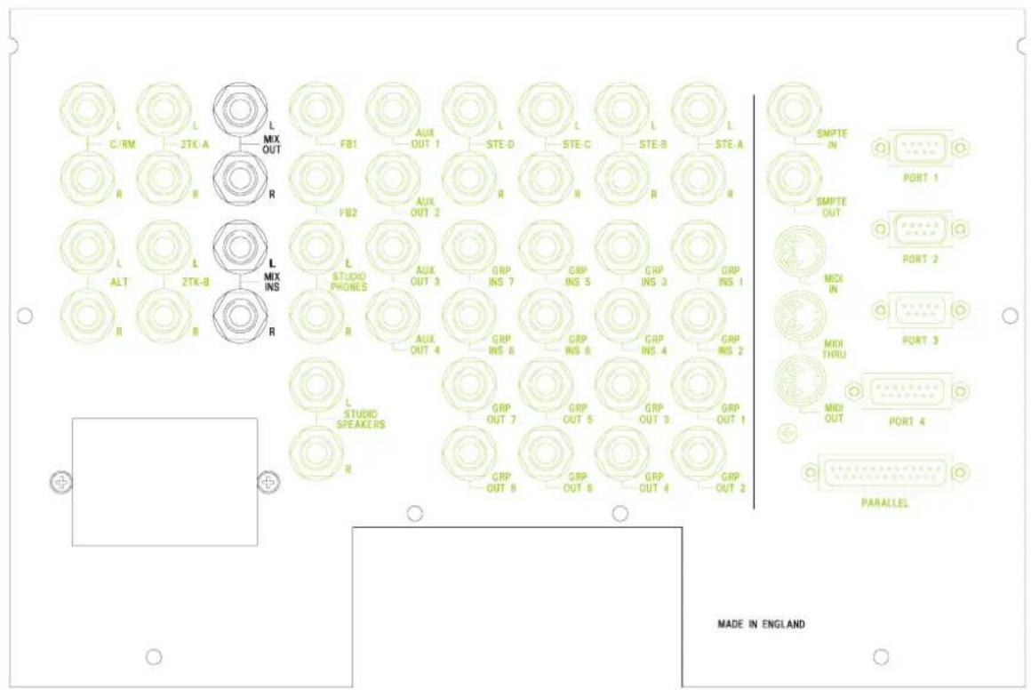
The DC2020 Patchbay is an 8-module wide panel which provides patching for up to 40 inputs, master functions and a maximum of 120 tie lines.
The following simplified diagrams show how the Bantam-type sockets are wired. The complete list of EDAC plug connections is given in Chapter 2.
The diagram on the right shows the convention used in drawing the sockets.
![graph TD A["Non-break Contact\n(Makes contact with inserted plug)"] --> B["Break Contact\n(Disconnects when plug is inserted)"]](/content/2026/06/1370664/images/8dfad522b32918b2d3fe1d94abcd3b92ab760e93879728952cd3d37ba109d0f4.jpg)
Line Inputs 1-24
![graph TD A["Line Inputs EDAC"] --> B["Line Input n Normalling"] B --> C["Line normalling Patchcard, located just above the tie lines"] C --> D["To Line Input n on console"] E["From Channel Input n"] --> F["CH OUT n"] F --> G["Tape Set EDAC N"] H["To Monitor Input n"] --> I["TP RET n"] I --> J["MON I…](/content/2026/06/1370664/images/5c5449f5d3b167c1ef58d972521531a195736919cbc55c97db7a694d7c3ddd7c.jpg)
Line Inputs 25-40
Input Channel 25-40
n
LINE IN

Note: Line Inputs 25 to 40 appear on their associated input patchcard only, they do not have a normalling patchcard.
![graph LR A["From Insert Send Amp."] --> B["INS SND n"] B --> C["To Insert Return Amp."] D["INS RET n"] --> E["INS SND n"] E --> F["To Insert Return Amp."]](/content/2026/06/1370664/images/33d5eb42c77df7e2903ce68d1b1d56d5441406e6fc50d2d547a07c2feddbf0f6.jpg)

![graph TD A["TP RET n"] --> B["AND"] C["MON IN n"] --> D["AND"] B --> E["Output"] D --> E E --> F["To Monitor Input n"]](/content/2026/06/1370664/images/06d9e4f7fdea5f83c642979d55b94004bea57d5109adb76b788b1a5977896bd7.jpg)
Group Inserts
Group Inserts
![graph TD A["From Group Send Amp."] --> B["SND"] B --> C["To Group Return Amp."] D["RET"] --> E["To Group Return Amp."] style A fill:#f9f,stroke:#333 style D fill:#f9f,stroke:#333 style B fill:#ccf,stroke:#333 style E fill:#ccf,stroke:#333](/content/2026/06/1370664/images/3950128305a9a826c78b274a0204fa22d6dbe615803ca7deefa5ad2fe2e3e4ff.jpg)
Group Outputs
Group Outputs
![graph TD A["From Group Output n"] --> B["Group OUTPUT n"] B --> C["Output n"]](/content/2026/06/1370664/images/cfae465c31f43f415a9f22b2a3fef227f972f048a17f65c7a46ecde09a9d2807.jpg)
SMPTE Timecode
SMPTE Timecode
![graph TD A["From SMPTE Sender"] --> B["SMPTE OUT on back of console"] B --> C["SMPTE OUT on patchbay"] D["To SMPTE Reader"] --> E["SMPTE IN on back of console"] E --> F["SMPTE IN on patchbay"]](/content/2026/06/1370664/images/1cb2de1a9fb3b9eb2d311b02e03881490f2ec527cf613f40767606e347912c13.jpg)
Stereo Inputs
STEREO INPUTS
![graph LR A["STE IN on EDAC"] --> B["To Stereo Input on Console"] B --> C["L or R"] C --> D["n"]](/content/2026/06/1370664/images/1d6535291992f14de54a6f9a1f7554c931675e626aa81dc4635c2ce33b650a5a.jpg)
Aux Outputs
Aux Outputs
![graph LR A["Aux Output From Console."] --> B["UX OUTPUT"] B --> C["EDAC"] style A fill:#f9f,stroke:#333 style C fill:#ccf,stroke:#333](/content/2026/06/1370664/images/53284a79d0526f1ce8627ad24fe7500cd1a59580eba64a01b1588c068f70374b.jpg)
Foldback Outputs
Foldback Outputs
![graph LR A["Foldback Output From Console."] --> B["FOLDBACK O/Ps"] B --> C["F/B OUTPUT ON EDAC"] C --> D["Feedback Loop"] D --> E["n-bit Delay"]](/content/2026/06/1370664/images/e72683481fdd368641be0b82fccfd27779bc3e2f847fe2b604224c647a5d4967.jpg)
Studio Phones
Studio Phones Outputs
![graph LR A["Studio Phones Output From Console."] --> B["L or R"] B --> C["EDAC"] C --> D["Output"]](/content/2026/06/1370664/images/d1e470adf2c04876afb751b610afbe4a66a29b8f2b41201b36eff888b8fc2f59.jpg)
Studio Speakers
Studio Speakers Outputs
![graph LR A["Studio Speakers Output From Console."] --> B["STUDIO SPEAKERS L or R"] B --> C["STUDIO SPEAKERS OUTPUT ON EDAC"] C --> D["Output"]](/content/2026/06/1370664/images/4cd23f1d83478ba040e7af1edbfaf771caf4038234e67cab3cf596e5ef9176d6.jpg)
Mix Inserts & 2-Track Sends
Mix Outputs and 2-Track Sends
![graph TD A["From Mix Output L or R"] --> B["2-TRK A L or R"] A --> C["2-TRK B L or R"] B --> D["Mix and 2-Trk Outputs on EDAC"] C --> D D --> E["MIX OUTPUT L or R"]](/content/2026/06/1370664/images/f3f9b1ebdedc0d66b629a0c4f904b8726f662081e175babf4ad419cb86790556.jpg)
2-Track Returns
![graph LR A["2-TRK Inputs on EDAC"] --> B["2-TRK A or B"] B --> C["To 2-Trk Input in Console"] C --> D["Feedback Loop"] D --> B](/content/2026/06/1370664/images/49f1bc1643004281196b0f992e056ab66be0ff46d7f7703273ad6563774d88b0.jpg)
Control-room & Alternative Speaker Outputs
![graph TD A["CROOM OUTPUT\nL or R"] --> B["CRM OUTPUT\nON EDAC"] C["CROOM OUTPUT\nFrom Console"] --> B D["ALT OUTPUT\nL or R"] --> B E["Alternative Speaker\nOutput From Console"] --> B B --> F["ALT OUTPUT\nON EDAC"]](/content/2026/06/1370664/images/8030ae75a1afa7ef66224d19ce4ddf69c2ae7b86d1a27282d2f0750088a20c63.jpg)
Parallel Sockets

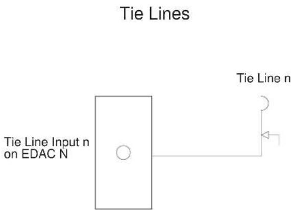
Tie Lines
Automation Guide
Introduction
Introduction to the Automation
Control Panel
The Central Control Panel is the user interface for the Automation System.
The Automation Control Panel appears as follows:

Screen
The Screen is a touch-sensitive LCD unit. There are 60 touch-sensitive areas on the display: 10 columns by 6 rows. The display itself consists of 76800 individual pixels, arranged as 320 columns by 240 rows.
To the right of the Screen there is a small thumbwheel. This adjusts the contrast of the screen for optimum viewing characteristics.
Most of the screen pages follow the format shown below. There are a number of areas on the screen: The Screen Title area, the Subsidiary Data area, the Cursor Line (which is touch-sensitive on most pages), the Scroll Bar with its touch-sensitive Up and Down areas, and the Touch-pads.

Keyboard
There are 22 buttons, some with illumination, which are for the functions most commonly used during mixing; there is also a Jog Wheel which is used for selecting pages and timecodes. The Jog Wheel may also be used to control the Tape Machine, providing that the Tape Machine will support this function.
The 22 buttons are in several groups, according to functionality. They are described below.
Tape Machine Manual Control
Manual control of the tape machine is achieved with the five momentary buttons which are located on the lower part of the Central Control Panel. These buttons, which are illuminated, are:
REW, FF, PLAY, STOP and RECORD. The Tape Machine must, of course, be suitable for remote control.
In addition to the manual command switches there are further commands for moving the tape. These are:
LOC0: Pressing LOC0 will cause the tape to re/wind to the position stored in LOCATE0. LOCATE0 is stored as a time-code value.
LOC1 is similar to LOC0.
AUTOPLAY is selected by pressing the AUTOPLAY button, a LED above the button glows to indicate selection. It is deselected by pressing the AUTOPLAY button again. If AUTOPLAY is selected and a locate key (LOCATE0, LOCATE1, DROP IN or DROP OUT) is pressed, then the tape will re/wind to the Cue point and start playing. If AUTOPLAY is not selected then the tape will stop at the Cue point.
Note: AUTOPLAY only operates when a locate button has been used. If a cue point is selected via the touch-screen, the tape will move to the selected location and stop.
AUTORETURN is selected in a similar way to AUTOPLAY.
If AUTORETURN is selected and the tape rolls past the LOCATE1 position the tape will rewind to LOCATE0 (unless Record Enable or Preview is selected). If AUTOPLAY is selected the tape will start playing again from LOCATE0. If LOCATE0 is after LOCATE1 then AUTORETURN cannot be selected.
The STORE button is used to enter the tape positions which are stored in LOCATE0 and LOCATE1. The position to be stored is selected from a list of cue points on the page. Holding down STORE and pressing LOC0 or LOC1 will store the selected Cue point on the LCD in the appropriate locate point.
Track Record Enable
The DROP IN and DROP OUT buttons are used to set the drop-in and drop-out points for recording onto the tape machine. They are set up in a similar way to LOCATE0 and LOCATE1, i.e. any cue point in the cue list may be selected.
The DROP IN and DROP OUT buttons are also 'locate keys': when they are pressed the tape machine will re/wind to them, and start playing if AUTOPLAY is selected. If Record Enable or Preview are selected, and Auto Return is selected, then when the tape plays through the Drop out point, the tape will rewind to the Drop In point. It will play if again if Auto Play is selected.
Note: pre-roll and post-roll times may be set up for the Locate points and the Drop In and Drop Out points.
RECORD ENABLE is selected by pressing the RECORD ENABLE button: a LED above the switch glows to indicate selection. It is deselected by pressing the RECORD ENABLE button again.
The Drop In and Drop Out points become active when RECORD ENABLE is selected, i.e. the enabled tracks on the tape machine will drop into record when the tape plays through, or starts from, the Drop In point. Similarly, the tracks will drop out of record when the tape plays through the Drop Out point.
Note: the Sync. head on the tape machine should be selected when RECORD ENABLE is selected. This is done automatically on supported tape machines.
PREVIEW is selected by pressing the PREVIEW button, a LED above the switch glows to indicate selection. It is deselected by pressing the PREVIEW button again.
The tape machine will not drop into record at the Drop In point when PREVIEW is selected; Instead, the inputs of the channels which would have been recorded are monitored between the RECORD IN and RECORD OUT points. This allows the material to be previewed.
The Repro. head on the tape machine should be selected when RECORD PREVIEW is selected. This is done automatically on supported tape machines.
When RECORD ENABLE is selected, tracks may be individually enabled by pressing the SEL switch (located next to the fader).
Individual tracks on the tape machine may be record enabled by using the appropriate switches on the tape machine, or in the case of supported machines, by using the Record Enable page which may be displayed on the Automation Display.
Jog Wheel
The Jog Wheel has a variety of functions, as follows:
Associated with the Jog Wheel is the SEARCH button. When the SEARCH button is selected it causes the Jog Wheel to become a shuttle control, jogging the tape backwards and forwards relative to a timecode reading. This is only available with supported tape machines. When SEARCH is not selected, the Jog Wheel is used for scrolling the LCD, and for setting numerical values on the LCD.
The Jog Wheel also has an integral switch which is activated by pressing down on the Jog Wheel. It is used in the alphanumeric and timecode editing screens.
Mix Automation
Automated Mixing is selected by pressing the MIX ON button, a LED beside the switch glows to indicate selection. It is deselected by pressing the MIX ON button again.
The ABORT button is used if you decide that you do not want to save a new mix. The adjacent LED glows when ABORT is active.
The TRANSFER button is used to create a cue in the cue list. The timecode associated with the cue is the timecode at the instant the TRANSFER button is pressed.
The SETUP button takes you straight into the Set-up Screen.
The GLIDEBACK button switches GLIDEBACK mode on and off: an adjacent LED indicates its status.
Glideback determines how motorised faders react when they are in Armed mode, and when they change from Write to Read Mode.
The MODE SNAP button may be used at any time to store a snapshot of the modes of all of the Automated functions. Only one such snapshot may be stored at any time.
To store a snapshot you press and hold the STORE button and then press the MODE SNAP button.
To recall the snapshot you press the MODE SNAP button.
The GROUP ASSIGN button takes you to the GROUP ASSIGN page. When the Group Assign page is active, input channels may be assigned to the Control Groups by using the SEL switches on the channels.
Disk Drives
A 3.5 inch 1.44Mbyte floppy disk drive is mounted underneath the armrest. It is used as the removable storage medium for the system. The disks use the same format as an IBM-compatible PC.
A Hard Disk Drive is fitted internally.
Project Management
Introduction
The DC2020 features a project management system, designed to provide easy storage and retrieval of mix data. The system means that the console can be used by a large number of different engineers, each working on their own projects, and enables each engineer to store mixes for his/her various projects in a directory system, where they can be easily located and recalled in the future. In addition, other information and text relating to each mix can be stored in the same location, and can also be recalled later.
The directory system is accessed and displayed via the touch screen, but as each screen page only shows one level of the system at a time, it is not easy at first to visualise the structure by looking at the touch screen. The following diagram shows the structure of the directory system.
The Directory Structure
![graph TD A["Studio"] --> B["User 1 User 2 User 3"] A --> C["Fader Recall, Backup Depth, Password"] B --> D["Project 1 Project 2 Project 3"] C --> E["Memos, Elapsed Time"] D --> F["Title 1 Title 2 Title 3"] D --> G["Timecode, Frame Rate, Pre & Post-roll, Console Remapping, Channel & Track Lists, Mix…](/content/2026/06/1370664/images/2831176ca82242d7cdabd2d0bf8f44dc346062b24a701368bb8ada0bdc92fc51.jpg)
As shown, the system is a tree structure starting from the root directory, 'Studio'. Below this are a number of 'Users', below each User a number of 'Projects', below each project a number of 'Titles', and finally within each Title, a 'Cue List' and a number of 'Mix Passes'.
It is possible to create any number of Users, Projects, Titles and Mix Passes within each level, the only limit is the amount of Hard Disk storage available for mix data. Note that the mix data itself from each Mix Pass is only actually stored at the bottom of the directory system, within each Title file. No mix data is stored at any other level, so even if you create 50 User directories, you will not have used up any Hard Disk Space until you start to save mixes in one of those directories.
On power-up, the console defaults to the bottom level, known as the 'Mix Page', of the directory which was last being used. This allows mixing to begin immediately assuming the same user is still working on the same project. This page displays the Cue List for the last title worked on, plus some touch-pads to allow access to other pages and functions and the rest of the directory system.
So to view the directory system having powered up the console, carry out the following instructions:
Exit the Mix Page by pressing the 'Project' touch-pad on the touch screen, which moves you upwards in the directory system by one level. You are now on the Project Page.
Press the 'User' touch-pad on the screen, which moves you upwards one more level, to the User Page.
Press the 'Studio' touch-pad on the screen to take you up finally to the Studio Page, which is the top level in the directory system.
The Studio page
This consists of a list of Users, although with a new console from the factory, there will be only one 'default' user, 'User 0001'.
You can create as many user directories as necessary by pressing the 'New User' touch-pad on the screen, and name them by pressing the 'Edit User' touch-pad. A newly created User is given the default name 'User 000X' until it is edited.
Once you have more than one User directory, you can select the one you want by either turning the jog wheel on the computer surround, or touching the up or down arrows on the right hand side of the screen. This moves the list up or down through the cursor line (two horizontal lines in the centre of the screen).
To activate the selected user, either touch the screen in the central area, or press down on the jog wheel. In either case, you can only select the item which is between the two lines of the cursor line.
Selecting a User takes you down to the next level down on the Directory system, which is the User page.
Before exiting the Studio Page, let's have a look at the peripheral pages available at this level. Press the 'Studio Config' touch-pad on the screen. This brings up the 'Studio Config' page, which allows you to set up or change the following:
"The name of the studio (set to 'Soundcraft' at the factory)"
"The type of tape machine being used (set to Midi Timecode Master at the factory)"
"The local date and time. (set to UK local time at the factory)"
To change any of these, simply touch the relevant part of the screen, which will bring up either the QWERTY keyboard, list of supported machines, or numerical keypad respectively.
Other information displayed on this page includes the percentage amount of free hard disk space available, the software version number being run, and the number of channels in the console.
Return to the Studio page by pressing 'OK' on the screen.
You may also visit the Studio Utilities page. A description of these utilities is given in the Automation Pages section of this manual.
Descending the Directory system
We can now work back down the directory system, looking in more detail at the other facilities available at each level. Select a User, as described earlier.
The User Page
The User page displays a list of the Projects available for the currently selected User, and as with the Studio page, with a new console from the factory there will be only one 'default' project, 'Project 0001'. You can create as many Projects as necessary, using the New Project touch-pad on the screen, and name them using the Edit User touch-pad.
There is a User Configuration page and a User Utilities page which are accessible via touch-pads.
A Project is selected in the same way as for the User, and selecting a Project takes you down to the next level down on the Directory system, which is the Project page.
The Project page
The Project page displays a list of all the Titles available in the currently-selected Project, and with a new console from the factory there will be only one 'default' Title, 'Title0001'.
You can create as many Titles as necessary, using the New Title touch-pad on the screen, and name them using the Edit Title touch-pad.
A Title is selected in the same way as for the previous pages, and selecting a Title takes you down to the next level down on the Directory system, which is the Mix page.
The Mix Page
We have now returned to the page which is always displayed immediately after power-up. The console remembers which directory you were working in when the power is turned off, and returns to the same place on power-up.
The Mix page has a slightly different format to the Studio, User and Project pages. It displays the 'Cue List' for the currently selected Title, as well as touch-pads to access other automation functions, the most important being the list of 'Mix Passes' associated with the Title. This is accessed by pressing the Mix List touch-pad on the screen. (With a new console from the factory, the list will be empty and will say 'No Mixes')
The Mix List is very useful, as it allows you to keep track of the number of Mixes you have saved for the current Title, the size of the data file for each mix, the date and time the mix was saved as well as allowing you to select any previous mix and
recall it, delete unwanted mixes or 'protect' valuable mixes to guard against accidental deletion. You can also name each individual mix if required, although the system gives each mix a default number as they are created, so naming is not essential.
The Mix list is exited by selecting the required mix using the jog wheel or side-arrows on the screen, in the same way as for the other directory pages.
Selecting a mix returns you to the Mix page, with the newly selected mix pass loaded and ready to play. The name of the mix (if previously entered) and its number are displayed at the top of the screen. This will also say 'No Mixes' if the console has never been used before.
The Automation Pages
The Automation Pages
The Pages which appear on the Automation System's screen belong to either the Main Automation System or to the Setup System. There is one page which is in neither of these systems: the Group Assignments page is accessed directly from the Group Assign button on the Automation Panel.
The Main Automation System
The interconnection map for this system is as follows:
![graph TD A["Studio Utilities"] --> B["Studio"] C["User Utilities"] --> D["User"] E["Project Utilities"] --> F["Project"] G["Title Utilities"] --> H["Mix"] I["Track List"] --> J["Mix Info"] K["Channel List"] --> L["Mix List"] B --> M["Studio Config"] D --> N["User Config"] F --> O["Project Config"] H…](/content/2026/06/1370664/images/dfe65c7b8477f94e7784e8aebbf2e69d86ea6e5effcf351324e8865e8d57baf7.jpg)
The hierarchy is based on the directory structure of the disk drive. The directory structure has a top level which holds Studio Information. This directory contains other directories: one for each of the Users.
Each User may have a number of Projects, and within each Project there may be a
number of Titles. The Title directory is the bottom level of the directory structure: individual mix passes are stored as files in the Title directory.
Configuration data is stored on disk. This data is stored at an appropriate level in the directory structure. For example, a User may set up a password at the user level: this would allow access to any of the user's Projects. As a further example, the timecode frame-rate is held in the Title directory: this allows a different frame-rate to be set up for different titles.
At any one time, there is a current directory path of user/project/title. This is where the user is currently working. When the console is powered down and then powered up again, the system always goes back to the mix page of the current path, i.e. the same path which was is use when the system was powered down.
Note: when the console is powered on for the first time, the system creates a default path of USER0/PROJECT0/TITLE0. This allows you to begin mixing immediately.
When a page is selected, some of the touch-pads on it may be inactive due to the context of what is currently happening. Buttons which are inactive are marked with a diagonal cross.
Setup System
The Setup system is accessed by pressing the Setup button on the Automation panel. The page interconnection map is shown below.
![graph TD A["Setup Menu"] --> B["Meter-bridge Setup"] A --> C["Default Mode On Stop"] A --> D["Switch Select On Tape Stop"] A --> E["Tape Machine Select"] A --> F["Monitor SIP Safe"] A --> G["Channel SIP Safe"] A --> H["Timecode Generator"] A --> I["Default Settings"] A --> J["MIDI Events"] A --> K["…](/content/2026/06/1370664/images/beed2b5c9d59e4ec10cdd98feb361e1cfa899f600cb6461c69f4b66a98c23722.jpg)
In the following pages in the manual, any automation pages which belong to the Main Automation System are headed with a black banner with white text. The pages which are in the Setup System are headed with a grey banner with black text.
The Alphanumeric Keypad appears as follows:

The functionality of this page is probably self-evident. However it will be helpful if the following features are brought to your attention:
Edit Line
The text to be entered/edited is displayed at the top of the screen. The character cursor position is indicated by a reverse-video character.
Jog Wheel
This may be used to move the cursor position. You may also insert extra characters by pressing the wheel.
Special Keys
Shift. Press to make the next letter pressed an upper case letter, or to select the symbols above the numbers.
Lck. This is a letter shift lock
Delete (<-). This deletes the character at the cursor position and moves the cursor position to the left.
OK. This returns you to the previous page and inserts the text, which is in the Edit Line, into the previous page.
Cancel. This returns you to the previous page, but it does not insert the text, which is in the Edit Line, into the previous page.
The Channel List page appears as follows:

The following information is presented:
Screen Title Area
Title only.
Scrollable Data
The list of Channels together with a description of each input is displayed.
To view the description for a particular Channel, scroll the data until the required Channel is in the Cursor Line. To add a description, touch the Cursor Line: a list of instrument types will be displayed; following the selection of one of these, a further list of instruments of the appropriate type will be displayed. Choosing one of these will cause this choice to be entered against the Channel in question.
Touch-pads
Insert. Pressing this inserts a new line into the Channel List.
Delete. Pressing this deletes the current line in the Channel List.
Blank Channel. Pressing this deletes the entry for the current line.
Copy to Tracks. Pressing this copies the entries to the Track List.
Edit. Pressing this allows you to edit the entry for the current line. This is done via the Alphanumeric keypad page.
Print. This sends the list to the printer port.
Cancel. Pressing this returns you to the Old Mixes screen without saving any changes.
OK. Pressing this returns you to the Old Mixes screen and saves any changes.
The Channel Solo-in-Place Safe page appears as follows:

This page allows you to set and clear the SIP safe status of individual Channels. Channels which are set to safe are shown in reverse text.
Set all safe. Pressing this sets the Safe status of all of the Channels.
Clear all safe. Pressing this clears the Safe status of all of the Channels.
Monitor SIP Safe. Pressing this takes you to the Monitor SIP Safe page.
Stereo Inputs. Pressing this takes you to the Stereo Inputs Safe page.
The Modes page appears as follows:
![graph TD A["Default mode on stop"] --> B["Switches"] A --> C["Faders"] A --> D["Master Switches"] A --> E["Master Fader"] F["Global Status"] --> G["Switches"] F --> H["Faders"] F --> I["Switch Select"]](/content/2026/06/1370664/images/56821c29d635fdb325bcddf033839cb464fb2207646ca73a385a2348cb1b57ee.jpg)
Touch-pads
Default Mode on stop
These Touch-pads allow you to define the modes which the switches and faders will go into when the Tape Machine stops. The options are: ARMED, WRITE, MANUAL and READ.
In practice you should set these to Read or Armed as these are modes where the existing mix data will be played back. This reduces the chance of accidentally overwriting a mix which is approaching perfection.
Global Status
These Touch-pads allow you to select or de-select the effect of the Global Mode switches on the Stereo Master panel. The options are: ON and OFF.
Switch Select. Pressing this takes you to the Switch Select On Tape Stop page.
Exit
To Exit, press the Set-up button.
The Default Settings page appears as follows:

The Frame Rate is the default setting for a newly-created Title. The value in the touch-pad may be cycled through by repeated pressing.
Fine Tuning Of Moving Faders
It is possible to fine-tine the motion of the faders to optimise the fader movements for either quiet operation or for the fastest response, depending on the demands of the application.
The figure in the Fader Gain touch pad may be set to a value from 0 to 4095. The higher this figure is, the faster the faders will move. Values below 300 are not recommended.
To change the value, press Fader Gain. A numeric keypad will then be displayed and you may change the number using the number buttons or the jog wheel. Press OK to enter the number.
The new number will be displayed but it will not be put into effect until you press the Change Gain button.
The appearance of the Edit Midi Events page changes according to the Event Type.
The blank Event screen appears as follows.
Edit Midi Event
Event Type


Note: Extra fields appear according to the Event type selected. To change the event type, press the Event type field. You will be presented with a list of options.
Touch Pads
Test. This transmits the currently displayed event. This is useful for testing purposes.
OK. This writes any changes into the Event list
Cancel. This exits without saving any changes.
The Glideback page appears as follows:
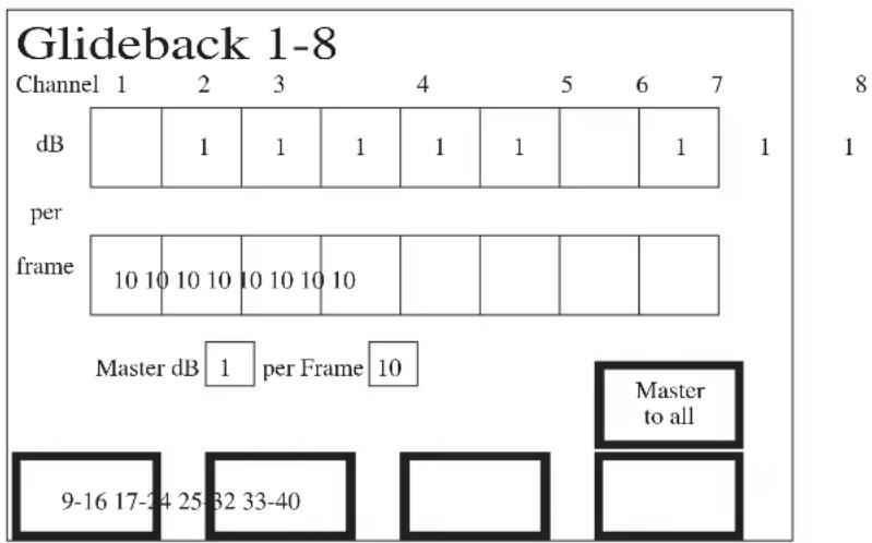
Touch-pads
The Glide rate is expressed in dB per frame. The default setting is 1dB per 10 frames. Pressing any of the dB or frames Touch-pads will cause a small numeric keypad to be displayed. This allows you to enter a new value for the appropriate parameter. The minimum value which you may enter for any of these parameters is 1, and the maximum is 99.
1-8, 9-16, 17-24, 25-32. These Touch-pads are interactive with the range of channels which is being displayed. They are used to change the range of inputs for which settings are displayed on the screen.
Master to all. Pressing this causes the settings which are stored for the Master Fader to be copied to all the other automated faders.
Exit
To exit, press the SETUP button on the Automation panel.
The Group Assignments page is accessed by pressing the Group Assign button on the Automation panel. It appears as follows:

This page shows which Control Group, if any, each Input is assigned to.
To assign Input Channels to Control Groups proceed as follows:
- Press the GROUP ASSIGN button on the Automation Panel, the green LED will glow to indicate that the mode is active, and the Group Assign page will be displayed on the screen.
- Press the appropriate Select Group touch-pad for the particular Control Group you wish to assign Mono Inputs to. The touch-pad in question will then be displayed in reverse video to indicate that this is the currently selected Group.
- Press the SEL switch on the Inputs you wish to assign. The appropriate Control Group Assign LED on the Mono Input will glow. In addition the small square on the screen which represents the Monitor will be displayed in reverse video.
Touch-pads
Select Group 1 /2 /3 /4. Pressing these allows you to assign individual Inputs to Control Groups. Press the SEL switch on an Input to assign it to the currently-selected Group.
Clear Group 1 /2 /3 /4. Pressing these removes all of the assigned channels from the Group in question.
Note: The Group Assignments are stored against each Title: they will, therefore, be reassigned every time a different Title is selected.
The Group Assignments are not put into effect until you exit from this page. This is done by pressing the Group Assign button again.
The Meterbridge Set-up page appears as follows:
![graph TD A["Meter Bridge Setup"] --> B["1-8 9-16 Return Return"] B --> C["Return Send Return"] C --> D["17-24 25-32 33-40"] D --> E[" "] F["MIX CRM"] --> G["Mix"] G --> H["Control Room"] H --> I["STE GRP"] I --> J["Stereo Inputs"] J --> K["Groups"] L["Brightness"] --> M["←"] M --> N[" "] N --> O["→"…](/content/2026/06/1370664/images/4577cb142df653a5e484acf3d6505e730cef54488ce167a1a95ee723e76c3faf.jpg)
Touch-pads
The meters for the input channels are switched, in groups of eight, between following the tape send or tape return signals. The Send / Return Touch-pads are used to control each group-of-eight. These touch-pads have a toggling action.
The MIX/CRM Meter may be switched to follow the Mix output or the Control-room output by using the, 'Mix' or the, 'Control Room' Touch-pads. The currently selected settings are shown in reverse text.
If Mix is selected the meters operate as follows: when you use a PFL switch, the meters will automatically switch to CRM so that the PFL bus is metered. When all PFLs are cleared the meters will switch back to Mix.
The STE/GRP Meters may be switched to follow the Stereo Inputs or the Stereo Groups outputs by using the, 'Stereo Inputs' or the, 'Groups' Touch-pads. The currently selected settings are shown in reverse text.
The meters may be set to obey one of three meter laws: this is done via the, 'VU', 'PPM', or the, 'Peak Hold' Touch-pads.
Slider Bar
The brightness of the meter LEDS is controlled by the slider bar: this has a touch-sensitive direction control on each end. The relative brightness setting is indicated by the position of the slider.
Exit
To exit from this page, press the SETUP button on the Control Panel.
The Midi Events page appears as follows:

The following information is presented:
Screen Title Area
The page title
Subsidiary Data Area
The Title, the Project and the User.
Scrollable Data
The list of MIDI events is displayed in timecode order. The Event Type or the Event Name may be displayed. If the Event Type is blank then the Midi Event is a NO EVENT.
If you press the cursor line the displayed MIDI event will be output. This is useful for testing MIDI commands.
Touch-pads
Edit event. This takes you to the Edit Midi Event page
Copy from Cue List. Pressing this will copy into the existing list all the timecodes from the cue list. The Midi Event associated with these timecodes will be No Events. You may edit these if you wish.
Playback ON/Playback OFF. This toggles between the two settings. Playback must be ON to enable MIDI codes to be transmitted against timecode. Playback is on when the touchpad displays, 'Playback ON'.
New Event. This inserts a new NO EVENT command with the currently-displayed timecode.
Edit Name. This allows you to edit the Event Name (even if Event Type is currently being displayed). The default name given to all Midi Events is MIDI EVENT X
where X is the next available number. Note that the numbers are not in timecode order: they are in the order that the Midi Events were inserted into the list.
Edit Timecode. This allows you to edit the timecode value of the Midi Event which is displayed in the Cursor Line.
Delete Event. This deletes the Midi Event which is displayed in the Cursor Line.
Display Names/Display Events. Toggles between displaying the Event Types and Event Names. Note that if the event type for a particular event is blank, the event is a NO TYPE event.
The Mix page appears as follows:

The following information is presented:
Screen Title Area
The Mix name. Note that the Pass Number is shown at the top right of the screen.
Subsidiary Data Area
The Title name, the Percentage of disk space which is free, the Project name and the User name.
Scrollable Data
The list of Cue Points for the Mix are displayed.
If you touch the Cursor Line, the tape machine will transport to the appropriate Cue (providing that the tape machine supports this function).
The four cue points, LOCATE0, LOCATE1, DROP IN and DROP OUT, are shown against their assigned cues as L0, L1, D1 and DO.
Touch-pads
Title Config. This takes you to the Title Configuration Page.
Project. This takes you to the Project page.
Mix List. This takes you to the Mix List page.
New Mix. This prepares a new Mix number with no recorded actions, and drops all automated functions into write mode, ready to start a new Mix. This allows you to try again from scratch. The previous Mix is, of course, saved on disk and you may come back to it at a later stage.
Edit Cue Name. This, not surprisingly, allows you to edit the Cue name.
Edit Timecode. This presents a small numeric keypad on the screen. This allows you to enter new time information into the Cue which is on the Cursor Line. You may also use the Jog Wheel to change the time information frame-by-frame.
Delete Cue. This deletes the Cue which is in the Cursor Line.
Title Utilities. Pressing this takes you to the Title Utilities page.
Mix Information
The Mix Information page appears as follows:
The following information is presented:

Screen Title Area
Title only.
Scrollable Data
The following fields are available within the scrollable area. Each of them may be positioned within the Cursor Line, and selected by touching the Cursor Line.
The data which you enter here is stored for information only: it has no meaning to the Automation system.
Tape Speed. Touching this field whilst it is in the Cursor Line takes you to the Alphanumeric Keypad page.
Noise reduction. Touching this field whilst it is in the Cursor Line takes you to the Alphanumeric Keypad page.
Sample Rate. Touching this field whilst it is in the Cursor Line takes you to the Alphanumeric Keypad page.
Client. Touching this field whilst it is in the Cursor Line takes you to the Alphanumeric Keypad page.
Producer. Touching this field whilst it is in the Cursor Line takes you to the Alphanumeric Keypad page.
Artist. Touching this field whilst it is in the Cursor Line takes you to the Alphanumeric Keypad page.
Engineer. Touching this field whilst it is in the Cursor Line takes you to the Alphanumeric Keypad page.
Memo. Touching this field whilst it is in the Cursor Line takes you to the Alphanumeric Keypad page.
Touch-pads
Print Info. This prints the Mix Information to the parallel port.
Track List. This takes you to the Track List page.
Channel List. This takes you to the Channel List page.
OK. This returns you to the Mix List page.
The Mix List page appears as follows:

The following information is presented:
Screen Title Area
The Title name.
Subsidiary Data Area
The Project and User names.
Scrollable Data
The list of Mix passes which have been saved for the Title are displayed.
To select a particular Mix and to go back to the Mix Page, scroll the data until the required Mix is in the Cursor Line, then touch the Cursor Line. The current Mix pass is indicated by a '*' to the left of the Mix.
Touch-pads
Mix Info. This takes you to the Mix Information page.
Mix Page. This takes you to the Mix page.
Display Date/Size. This toggles between displaying Name & Number of the Mix, and Date & Time the Mix was saved, plus its size in kBytes.
Edit Mix. This takes you to the Alphanumeric Keypad Page. You may then edit the Mix name which is in the Cursor Line.
Protect Mix. This will toggle the protect status of the Mix pass in the Cursor Line. A protected Mix is indicated by a 'P' next to its name. When a Mix is protected it cannot be deleted or amended, nor will it be written over when Mixes are automatically saved.
Delete Mix. This deletes the Mix in the Cursor Line.
Title Utilities. Pressing this takes you to the Title Utilities page.
The Monitor Solo-In-Place Safe page appears as follows:

This page allows you to set and clear the SIP safe status of individual Monitors. Monitors which are set to safe are shown in reverse text.
Touch-pads
Individual, Numbered pads. You may enable/disable individual Channels by using these.
Set all safe. Pressing this sets the Safe status of all of the Monitors.
Clear all safe. Pressing this clears the Safe status of all of the Monitors.
Channel SIP Safe. Pressing this takes you to the Channel SIP Safe page.
Stereo Inputs. Pressing this takes you to the Stereo Inputs Safe page.
On-Line Mix Edit Options
The On-Line Mix Edit Options page is selected via the Titles Utilities page. It appears as follows:

The Edit Mode touch-pad toggles between On and Off. When it is set to 'On' the shuttle wheel may be used to run the tape transport(s) forwards and backwards. This is especially useful if you are editing video sound-tracks: it allows you to enter automation moves to an accuracy of 1/4 frame (the video machine will also move under the control of the shuttle wheel, provided that the video machine is able to support this).
Assuming that Edit Mode is set to 'On', you may activate the shuttle wheel by pressing the SEARCH button.
Note: there is a quick method of toggling Edit Mode without having to go into this page - press and hold STORE followed by MIX ON. Repeating this sequence toggles Edit Mode to Off again.
Pressing the OK pad returns you to the Title Utilities page.
Note!
When On-line mixing you cannot scroll the timecode back once you have made a change to the mix, i.e. once you have:
- touched a fader which is in ARMED mode
- put a fader or switch into WRITE mode
- changed the status of a switch which is in ARMED mode
The editing principles when using the On-line mixing facility are identical to those which apply to mixing at normal PLAY speed (see section entitled Controlling the Faders & Switches on page 4.118). Bear in mind, though, that if you are On-line mixing, and you make a change to the mix with the timecode stationary, say at timecode X, you must scroll the timecode forward (even if only by 1/4 frame), before pressing STOP, if you wish for the change made at timecode X to be stored into the mix.
Also note that when On-line mixing is in use, the automatic mix saving to hard disk does not occur until the stop button is pressed (as is also the case with the normal mixing mode). The Mix On LED flashes to remind you that On-line edit is being used.
Presets
Warning!
It is important to state that presets cannot be added to a title which already contains cues or mixes.
Important Note!
It is not possible to access the Presets page when MIX ON is selected.
Should you press SETUP when MIX ON is selected, the SETUP menu has a cross displayed over the touch pad labelled Presets to indicate that the Presets facility is unavailable at the present time.
If you press the MIX ON button, the amber LED is switched off, but the screen is not re-drawn to make the Presets available. To access the Presets you must press the SETUP button to leave the SETUP menu, and then press SETUP again to re-enter the menu.
The SETUP menu then appears and shows that presets are available.
Presets
A preset stores the state of all the automated functions i.e.
- Monitor faders.
- Monitor cuts.
- Channel cuts.
- Aux1 ON/OFF.
- Aux3 ON/OFF.
- Stereo cuts.
- Group cuts.
It does not store any information about the status of Automation MODES, i.e. read, write, armed and manual.
Presets represent a convenient way to store important configurations. One user might choose to set up a number of presets that will likely be used in the recording/Mix process.
e.g. Useful groups of cuts.
- All Drum Channels.
- All Brass Channels.
- All except the Rhythm Section channels.
A Preset can be recalled by pressing the highlighted bar over the required Preset on the touch-screen.
Alternatively you may recall presets by assigning a timecode value to each one. If Playback On is selected, then when that timecode value is reached, that preset will be recalled.
It is intended that these timed presets could be used to create an initial mix (using the "Create Mix" option on the Preset Utilities page). For instance, someone working with film/video could set up a preset to co-incide with the start of each scene.

Press Pad Labelled PLAYBACK ON (Screen will Change As Shown Below).

The list of stored presets available is displayed. To return to the Set-Up menu press the Set Up key
Touch Pads:
Preset Utilities. This takes you to the preset utilities page.
Preset Utilities


- Create Mix: This creates a new mix based on the list of timed presets which has been created.
- Timecode sort: This arranges the list of presets on the presets page in the timecode order. The presets must be listed in sequential order prior to being played back against Timecode (PLAYBACK ON Mode).
Playback ON/ Playback OFF:
This pad is used to toggle the playback mode. When the pad is labelled PLAYBACK ON the playback mode is ON and next to each Preset name will be the timecode value at which the preset will be output.
When the pad is labelled PLAYBACK OFF the playback mode is OFF, and the reference number will be shown next to each preset name.
Overwrite Preset:
This will enable you to overwrite the settings associated with the current preset (i.e. The preset on the cursor line) with the current desk settings.
This is a potentially dangerous operation so the user is asked to confirm that the operation should in fact go ahead.
Replace: Are You Sure?


New Preset:
This will create a new preset to which the current desk settings are assigned. It will be labelled
Edit Name:
This will allow the user to give the current preset (i.e. the preset on the cursor line) a new label. Upon pressing the pad a "QWERTY" Keyboard will appear. The user can then type a new label and/or edit the label using the jog wheel.

Edit Timecode:
This can be used to edit the timecode value associated with each preset. Upon pressing the pad a numeric keypad will appear. The user can then enter a timecode value and/or edit a timecode value using the jog wheel.
Pressing the jog wheel tabs between
Hours < Minutes < Seconds < Frames
Spinning the jog wheel either increments or decrements the timecode by a unit defined by the position of the "=" symbol. i.e. Hours/Minutes/Seconds or Frames.

Delete Preset:
This will enable you to delete the current preset (i.e The presets on the cursor line)
Like Overwrite Preset, this is a potentially dangerous operation, so the user is asked to confirm whether you wish to delete the preset.
Delete Preset: Are You Sure?
Insert Preset:
This enables you to insert a new preset above the preset on the cursor line.
At this point it might be useful to mention the numbering scheme used to identify Presets.
The scheme has three levels
• Top Level Preset (e.g 1, 3, 17, 531)
• 2nd Level Preset (e.g 1.1, 1.2, 10.3, 70.7)
• 3rd Level Preset (e.g. 1.1.1, 1.2.3, 10.5.6)
If the user repeatedly inserts presets, the maximum allowable will be 10 within each reference no.
(i.e. 1.10, 2.3.10)
If there is room in the numbering scheme for a new preset, then it will be created above the cursor line.
| 1 | 1.1 | 1.1 | 2.3.6 | |
| Cursor Line | 2 | 2 | 1.2 | 2.3.7 |
| ↓ | ↓ | ↓ | ↓ | |
| 1 | 1.1 | 1.1 | "BEEP"↓ | |
| 1.1 | 1.2 | 1.1.1 | Means you can not insert here.You must Re-number first. | |
| Cursor Line | 2 | 2 | 1.2 |
Renumber Presets:
This will renumber the presets so that the number for each preset will only comprise one part (i.e. a single integer).
The Project page appears as follows:

The following information is presented:
Screen Title Area
Project Name
Subsidiary Data Area
User Name.
Scrollable Data
The list of Titles are displayed. To view the Mix Page of a Title, scroll the data until the required Title is in the Cursor Line, then touch the Cursor Line. The Mix page will then be displayed. A '*' on the left indicates the currently selected Title.
Touch-pads
Project Config. This takes you to the Project Configuration page.
User. This returns you to the User page.
Mix Page. This takes you to the most recently used Mix Page. The current content of the Cursor Line is irrelevant.
Protect Title. This protects the Project in the Cursor Line from being deleted. A 'P' on the right hand side of the Cursor Line indicates that protection is in place. A '!' indicates that a Mix in the Title is protected.
Edit Title. This takes you to the Alphanumeric Keypad Page. You may then edit the Title name which is in the Cursor Line.
New Title. This creates a new entry at the bottom of the Title list. It will be in the form, 'Title 0001'. The actual number will be the next available one in sequence.
Delete Title. This deletes the Title in the Cursor Line.
Project Utilities. Pressing this takes you to the Project Utilities page.
The Project Configuration page appears as follows:
Project config
Memo
Elapsed Time 0:11:18:25
OK
The following information is presented:
Screen Title Area
The page title only.
Memo Fields
There are two fields which may be used for notes. Each field may contain up to 30 characters.
To change the contents of a field, you may touch the field: the alphanumeric keypad will then be displayed.
Elapsed Time
This shows the time that has been spent on the Project in question. The fields show, from left to right, Days: Hours: Mins: Secs. The example on the screen above therefore shows 11 hours, 18 mins and 25 seconds. The elapsed time for the Project in question is only incrementing when the Project is selected (via the Project page): all other Projects, if there are any, are therefore not incrementing.
The time starts from zero when a Project is created (again, via the Project page).
Touch-pads
OK. This returns you to the Project page.
The Project Utilities menu appears as follows:
Project Utilities


![graph TD A["Duplicate Project"] --> B["Copy Floppy"] B --> C["Disable Screen"] C --> D["OK"]](/content/2026/06/1370664/images/4c70cd0c180d0dc1eb2c8e3a8e231ada143bd73a318943ea84b02aba89612dd0.jpg)
Touch Pads
Backup Project. This will backup the data, which relates to the Project, on the hard disk to floppy disks. You will be prompted to remove each floppy disk when it is full and to insert the next floppy. If there is data already on a floppy you will be prompted to confirm that you wish to over-write the data on it.
Readability of backups may be checked on a PC, or you may use the verify facility which is offered after the backup process has finished.
Restore Project. This restores data from floppy disks onto the hard disk.
Duplicate Project. This copies the current Project to its user. The copy has the same name as the original name plus (dup) as a prefix.
Change Mix Disk. Allows you to change the drive to which Mixes are saved.
Format Floppy. You will be prompted to insert a floppy disk in the drive. You will be warned if the disk is already formatted, and you will have the option to continue or not.
Copy Floppy. This allows you to make a backup copy of a floppy disk. You will be prompted to insert the Source disk or to cancel. Assuming that you insert a source disk and press 'Continue', the contents of the disk will be read into RAM. Then the system will prompt you to insert the Target disk and to press 'Continue'. The copy of the Source disk which is currently held in RAM will then be copied onto the Target disk.
Shutdown Console. This writes the contents of RAM to disk, closes all of the open disk files and then prompts you to switch the console off.
Recalibrate Console. This recalibrates the Automated Faders' Laws. This Utility takes approximately five minutes per bank of 8 Faders to execute.
Disable Screen. This allows you to clean the surface of the screen without activating any touch-pads.
OK. Press the OK touch-pad to return to the Project page.
The Record Enable page appears as follows:

This page allows you to enable and disable the Record status of individual Channels.
The REC LEDs (on the input strips) pulse whenever their respective Channel is record enabled. The pulsing changes to a constant illumination when the tape machine is actually recording.
Touch-pads
Individual, Numbered pads. You may enable/disable individual Channels by using these.
Enable All. This enables every Channel.
Disable All. This disables every Channel.
OK. This returns you to the Mix page
Note
Record enabling/disabling may also be done by pressing the Record Enable button on the Automation panel and then pressing the SEL switch on the required input strip.
The Record Track Remap page appears as follows:
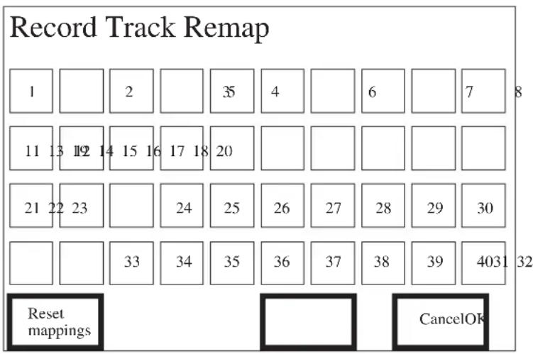
This facility allows you to use any track on a tape machine with any input channel on the console, and still retain control of the correct track when using drop-in and drop-out.
Touch Pads
Individual, Numbered pads. To swap two inputs with each other you press one of their numbers, followed by the other one. The numbers in the two pads in question will swap over.
It may be helpful to think of the pad itself as representing the physical input strip, and the number in it as representing the track number on the tape machine.
Reset Mappings. This resets everything back to the default values as shown in the diagram above.
OK. Pressing this implements any changes and returns you to the Mix page.
Cancel. Pressing this returns you to the Mix page without implementing any changes.
The Remap Console page appears as follows:

This facility allows you to swap the stored mix movements for one input with that of another input. This would be useful if, for example, an input strip failed during a Mix session. You could swap the affected input with an unused input (and swap the leads to the tape machine etc).
Touch Pads
Individual, Numbered pads. To swap two inputs with each other you press one of their numbers, followed by the other one. The numbers in the two pads in question will swap over.
It may be helpful to think of the pad itself as representing the physical input strip, and the number in it as representing stored moves in the Mix.
Reset Mappings. This resets everything back to the default values as shown in the diagram above.
OK. Pressing this implements any changes and returns you to the Mix page.
Cancel. Pressing this returns you to the Mix page without implementing any changes.
The Set-up menu is accessed by pressing the Set-up button on the Automation Control Panel. When the Menu is active the Set-up LED, which is next to the Set-up button, will be on.
The Setup Menu allows access to pages which, in turn, allow you to set-up the console as required. The information is saved separately with each Title. It is recalled each time a different Title is selected.
The Set-up Menu appears as follows:
Setup
![graph TD A["Meter Bridge"] --> B["Modes Glickback"] B --> C["Solos"] C --> D["Default Settings"]](/content/2026/06/1370664/images/797de3ae2788cca502c98ec6ed3054e1862ee53bcf5118b98da696fcd82bd34f.jpg)

![graph TD A["Presets"] --> B["Timecode Generator"] B --> C["Solos Remix"] C --> D["Machine Selects"]](/content/2026/06/1370664/images/c1604c11e442c58a2385239df1394566273c3c5a7d865f326c0b45294264a51d.jpg)
Touch-pads
The following Touch-pads are presented:
Meter Bridge. This takes you to the Meterbridge Set-up page.
Midi Events. This takes you to the Midi Events page.
Presets. This takes you to the Presets page.
Modes. This takes you to the Default Mode On Stop page.
Glideback. This takes you to the Glideback page.
Timecode Generator. This takes you to the Timecode Generator Page.
Solos. This takes you to the Monitor Solo-in-place page. You may also access the Channel Solo-in-place page and the Group/Stereo Safe page via the Monitor Solo-in-place page.
Solos Record. This is the default Solo mode of the console. Only the Monitor Cuts are actually cut on a Monitor Solo command, the Channel Solo will have no effect.
Solos Remix. This touch-pad activates the alternative mode. This mode causes a cut to the channels when a Monitor SIP is done, also the Monitors are cut when a Channel is soloed.
Default Settings. This takes you to the Default Settings page.
Stop Edit Options. This takes you to the Stop Edit Options page.
To Exit press the Set-up button again.
The Stereo Inputs Safe page appears as follows:
![graph TD A["Stereo SIP safe"] --> B["A"] B --> C["B"] C --> D["C"] D --> E["D"] F["Set All"] --> G["Clear All"] G --> H["Channel SIP Safe"] H --> I["Monitor SIP Safe"]](/content/2026/06/1370664/images/15a540df14a38af3d18bb16ad6127beea27e087911e55d718725b0bf8730cf65.jpg)
This page allows you to set and clear the SIP safe status of the Stereo Inputs.
Touch-pads
A, B, C, D. Pressing any of these makes the appropriate Stereo Input safe.
Set all. Pressing this sets the Safe status of all four Stereo Inputs.
Clear all. Pressing this clears the Safe status of all four Stereo Inputs.
Channel SIP Safe. Pressing this takes you to the Channel SIP Safe page.
Monitor SIP Safe. Pressing this takes you to the Monitor SIP Safe page.
The Stop Edit Options page appears as follows:
Stop Edit Options
Write Faders to end of Mix

Write Switches to end of Mix

Update Faders to end of Mix

Touch-pads
Each of the Touch-pads toggles between ON and OFF.
Write Fader to end of Mix. If this is set to ON, all the Faders which are in Write mode will have their positions, at which they happen to be when the tape machine is stopped, overwritten to the end of the Mix.
The touch-pad field automatically cancels to OFF after each Mix pass because this facility is potentially very destructive.
Write Switches to end of Mix. If this is set to ON, all the Switches which are in Write mode will have their settings, at which they happen to be when the tape machine is stopped, overwritten to the end of the Mix.
The touch-pad field automatically cancels to OFF after each Mix pass because this facility is potentially very destructive.
Update Fader to end of Mix. If this is set to ON, all the Faders which are in Armed mode will have any offset which exists, between their positions at which they happen to be when the tape machine is stopped and their previously recorded positions, added to the fader movements up to the end of the Mix.
Studio
The Studio page is at the top of the hierarchical tree. To get here from the Mix page, which appears after the DC2020 is powered on, do the following: In the Mix page press the Project touch-pad; this takes you to the Project page, then press the User touch-pad; this takes you to the User page, then press the Studio touch-pad; this will take you to the Studio page, which appears as follows:
| Studio: Soundcraft | |||
| ↑ | |||
| ■ | |||
| DC2000 User 0001 | |||
| DC2000 User 0002 DC2000 User 0003 | |||
| ↓ | |||
| Studio Config | Mix Page | Protect User | |
| Edit User | New User | Delete User | Studio Utilities |
The following information is presented:
Screen Title Area
The Studio name.
Scrollable Data
The list of current users is displayed.
To go to the User Page, scroll the data until the required User is in the Cursor Line, then touch the Cursor Line. A '*' on the left-hand side indicates the currently selected User.
Touch-pads
Studio Config. Pressing this takes you to the Studio Configuration Page.
Mix Page. Pressing this takes you to the most recently used Mix Page.
Protect User. Pressing this protects the User from being deleted. A 'P' on the right hand side of the Cursor Line indicates that protection is in place. A '!' on the right hand side of the Cursor Line indicates that a Project, Title or Mix in that User is protected and therefore the User cannot be deleted.
Edit User. Pressing this takes you to the Alphanumeric Keypad Page. You may then edit the User's name which is in the Cursor Line.
New User. Pressing this creates a new entry at the bottom of the user list. It will be in the form, 'User 0001'. The actual number will be the next available one in sequence.
Delete User. Pressing this deletes the User in the Cursor Line.
Studio Utilities. Pressing this takes you to the Studio Utilities page.
The Studio Configuration page appears as follows:

The following information is presented:
Screen Title Area
Software version number and date.
Subsidiary Data Area
Console Size, Floppy Disk Status, Hard Disk Status, the active drive to which mixes are currently being saved, and the percentage free space on the active drive.
Data Fields
The following data is available:
Studio Name. When this is in the Cursor Line, and you press the Cursor Line, the Studio name may be edited via the Alphanumeric Keypad page.
Tape Machine. When this is in the Cursor Line, and you press the Cursor Line, the Tape Machine Select panel is presented.
Time. The current Time is displayed and may be edited.
Date. The current Date is displayed and may be edited.
Touch-pads
Configure Port 1. This takes you to the Port Config. page. Not yet implemented.
Configure Port 2. This takes you to the Port Config. page. Not yet implemented.
Configure Port 3. This takes you to the Port Config. page. Not yet implemented.
OK. This returns you to the Studio page.
The Studio Utilities page appears as follows:
Studio utilities


![graph TD A["Identify Disk"] --> B["Copy Floppy"] B --> C["Disable Screen"] C --> D["OK"]](/content/2026/06/1370664/images/3b93b32f83abacf6ee5960ffbe2b0fd348071cf53e819d4ae46d15c5929b871d.jpg)
Touch-pads
Backup Console. This will backup the data on the hard disk to floppy disks. You will be prompted to remove each floppy disk when it is full and to insert the next floppy. If there is data already on a floppy you will be prompted to confirm that you wish to over-write the data on it.
Readability of backups may be checked on a PC, or you may use the verify facility which is offered after the backup process has finished.
Restore Console. This restores data from floppy disks onto the hard disk.
Identify Disk. This will tell you about the disk in the floppy drive. It can identify thr following types of disk: mix, backup, DC2020 program, password removal, MS-DOS or unformatted. You may also verify the disk, i.e. check that the disk is readable.
Change Mix Disk. Allows you to change the drive to which Mixes are saved.
Format Floppy. You will be prompted to insert a floppy disk in the drive. You will be warned if the disk is already formatted, and you will have the option to continue or not.
Copy Floppy. This allows you to make a backup copy of a floppy disk. You will be prompted to insert the Source disk or to cancel. Assuming that you insert a source disk and press 'Continue', the contents of the disk will be read into RAM. Then the system will prompt you to insert the Target disk and to press 'Continue'. The copy of the Source disk which is currently held in RAM will then be copied onto the Target disk.
Shutdown Console. This writes the contents of RAM to disk, closes all of the open disk files and then prompts you to switch the console off.
Recalibrate Console. This recalibrates the Automated Faders' Laws. This Utility takes approximately five minutes per bank of eight faders to execute.
Disable Screen. This allows you to clean the surface of the screen without activating any touch-pads.
OK. Press the OK touch-pad to return to the Studio page.
Switch Select On Tape Stop
The Switch Select On Tape Stop page appears as follows:
Switch select on tape stop
![graph TD A["Mon Cut"] --> B["ON"] C["Chan Cut"] --> D["ON"] E["Aux 1"] --> F["ON"] G["Aux 3"] --> H["ON"] I["Stereo Cut"] --> J["ON"] K["Group Cut"] --> L["ON"] M["Aux Master Cut"] --> N["ON"] O["Foldback Cut"] --> P["ON"] Q["Global Modes"] --> R["ON"]](/content/2026/06/1370664/images/1fc2efb4eab17c3daea76468e0adc184996d087d5a15dabdd740075fcf181588.jpg)
Touch-pads
The Touch-pads allow you to define which switches will be selected when the Tape Machine stops.
Global Modes. Pressing this takes you to the Default Mode On Stop page.
Exit
To Exit, press the Set-up button.
The Tape Machine Selection page appears as follows:
Tape Machine Selection
Tascam DA-88 (MTC)
Midi Timecode Master
LTC Timecode Client
Machine A
Machine B
Machine C
This page allows you to pre-select three tape machines from those which are currently available, and to then easily select one of these three machines.
To pre-select a machine touch one of the left-hand touch-pads. This will then display a list of the available machines which you may scroll through. Touching the cursor line will then insert the machine displayed in the cursor line into the touch-pad in question on the Tape Machine Selection page. This procedure may be repeated for the other two touch-pads.
To select one of the machines, you touch one of the right-hand pads: Machine A, B or C. The currently selected machine is shown in white text on a dark background.
Timecode Generator
The Timecode Generator is used to stripe tape on the tape machine. The timecode signal appears on the SMPTE out rearcon jack/patchbay socket.
The Timecode Set-up page appears as follows:
Timecode Generator
Reader Frame Rate
Generator Frame Rate
25
25
Start
00:00:00:00
RUN
STOP
Reader Frame Rate. This displays the frame rate for the timecode reader. The reader may be changed via the Title Configuration page.
Generator Frame Rate. This allows you to change the frame rate of the timecode which will be generated when you press Run.
Start. This is the start time of the generator. Press this pad to edit the value with the keypad or jog wheel.
Run. Press to make the generator run. The text is white on a black background when it is running.
Stop. Press to make the generator stop. The text is white on a black background when it is stopped.
Title Configuration
The Title Configuration page appears as follows:

The following information is presented:
Screen Title Area
Title only.
Data Fields
The following fields are available:
Locate Pre-roll. Pressing this presents a small numeric keypad on the screen. This allows you to enter or edit the Locate Pre-roll time. You may also use the Jog Wheel to change the time information frame-by-frame.
If AUTO PLAY is selected on the Control Panel, and you then press LOCATE0, the tape machine will wind the tape to the position which is equal to the pre-roll time before the LOCATE0 time. The tape will then start playing. For example, if the pre-roll time is set to 2 seconds, and LOCATE0 is set to 1:10:20:15, the tape would fast-wind to 1:10:18:15 and then play.
Locate Post-roll. Pressing this presents a small numeric keypad on the screen. This allows you to enter or edit the Locate Post-roll time. You may also use the Jog Wheel to change the time information frame-by-frame.
If AUTO RETURN is selected on the Control Panel, the tape machine will play the tape to the position which is equal to the post-roll time after the LOCATE1 time. The tape will then rewind to LOCATE0. For example, if the post-roll time is set to 3 seconds, and LOCATE1 is set to 1:15:25:03, the tape would stop and rewind at 1:15:28:03.
Drop-in Pre-roll. Pressing this presents a small numeric keypad on the screen. This allows you to enter or edit the Drop-in Pre-roll time. You may also use the Jog Wheel to change the time information frame-by-frame.
Drop-out Post-roll. Pressing this presents a small numeric keypad on the screen. This allows you to enter or edit the Drop-out Post-roll time. You may also use the Jog Wheel to change the time information frame-by-frame.
Using Drop-in Pre-roll and Drop-out Post-roll
If RECORD ENABLE is selected on the Control Panel, and you then press DROP IN, the tape machine will wind the tape to the position which is equal to the Drop-in pre-roll time before the Drop-in time. The tape will then start playing. At the Drop-In cue the tape machine will then drop-in to record on the selected tracks. For example, if the drop-in pre-roll time is set to 10 seconds, and Drop-in is set to 1:10:20:15, the tape would fast-wind to 1:10:10:15 and then play until 1:10:20:15, at which point it would drop-in to record.
The tape machine will play the tape to the position which is equal to the Drop-out post-roll time after the Drop-out time. The tape will then rewind to the Drop-in cue. For example, if the post-roll time is set to 3 seconds, and Drop-out is set to 1:15:25:03, the tape would stop and rewind at 1:15:28:03.
Note: If PREVIEW is selected instead of RECORD ENABLE the tape machine will not drop into record, instead, the input channel signal will replace the tape track signal on the control-room signal: This allows the artiste to practice an overdub.
Note: The Preview function may be executed as many times as you wish. The Record Enable function however will only execute once: at the end of the overdub the Control Panel will automatically go into Review Mode (this is indicated by the PREVIEW LED flashing). The Review function will then play the tape between the Drop-in minus Drop-in pre-roll, and the Drop-out plus Drop-out post-roll times.
Mix Offset. This facility is not yet implemented.
Mix Frame Rate. This field allows you to change the Timecode reader frame rate.
Note: You cannot change the Mix Frame Rate after a Mix has been started: specifically, once cue points have been inserted or fader movement data or switch position data have been recorded.
Mix Pass Save Option. This toggles between AUTO and OFF. When it is set to AUTO each mix pass is saved to disk when the tape machine is stopped, and the current Mix Pass number, which is displayed at the top right hand side of the Mix page, is incremented for the next Mix Pass. When this option is set to OFF the Mix pass is not saved to disk when the tape machine is stopped, the Mix Pass is however still present in RAM. The Mix will be saved to disk when you exit the Mix page.
This option is intended for use when small changes are being made to a long mix. It will reduce the time taken between mix passes.
This option is reset to Auto whenever a new Title is loaded.
Touch-pads
Record remap. This takes you to the Record Track Remap page.
Record Enable. This takes you to the Record Enable Page.
Remap Console. This takes you to the Remap Console Page.
OK. This returns you to the Studio page.
The Title Utilities menu appears as follows:
Title Utilities
![graph TD A["Backup Title"] --> B["Change Mix disk"] B --> C["Shutdown Console"] C --> D["On Line Mix Edit"] E["Restore Title"] --> F["Format Floppy"] F --> G["Recalibrate Console"] G --> H["Off Line Mix Edit"] I["Duplicate Title"] --> J["Copy Floppy"] J --> K["Disable Screen"] L["OK"] --> M["End"]](/content/2026/06/1370664/images/823e0fe38e5b05567771f929beb3fc9ef6abfabe46926dfd2002fb3cfd24ed60.jpg)
Touch Pads
Backup Title. This will backup the data, which relates to the Title, on the hard disk to floppy disks. You will be prompted to remove each floppy disk when it is full and to insert the next floppy. If there is data already on a floppy you will be prompted to confirm that you wish to over-write the data on it.
Readability of backups may be checked on a PC, or you may use the verify facility which is offered after the backup process has finished.
Restore Title. This restores data from floppy disks onto the hard disk.
Duplicate Title. This copies the current Title to its Project. The copy has the same name as the original name plus (dup) as a prefix.
Change Mix Disk. Allows you to change the drive to which Mixes are saved.
Format Floppy. You will be prompted to insert a floppy disk in the drive. You will be warned if the disk is already formatted, and you will have the option to continue or not.
Copy Floppy. This allows you to make a backup copy of a floppy disk. You will be prompted to insert the Source disk or to cancel. Assuming that you insert a source disk and press 'Continue', the contents of the disk will be read into RAM. Then the system will prompt you to insert the Target disk and to press 'Continue'. The copy of the Source disk which is currently held in RAM will then be copied onto the Target disk.
Shutdown Console. This writes the contents of RAM to disk, closes all of the open disk files and then prompts you to switch the console off.
Recalibrate Console. This recalibrates the Automated Faders' Laws. This Utility takes approximately five minutes per bank of 8 Faders to execute.
Disable Screen. This allows you to clean the surface of the screen without activating any touch-pads. Press any Automation Panel button to activate the screen again.
OK. Press the OK touch-pad to return to the page from which you accessed the Title Utilities menu.
The Track List page appears as follows:

The following information is presented:
Screen Title Area
Title only.
Scrollable Data
The list of Tracks together with a description of each instrument is displayed.
To view the description for a particular Track, scroll the data until the required Track is in the Cursor Line. To add a description, touch the Cursor Line: a list of instrument types will be displayed; following the selection of one of these, a further list of instruments of the appropriate type will be displayed. Choosing one of these will cause this choice to be entered against the Track in question.
Touch-pads
Insert. Pressing this inserts a new line into the Track List.
Delete. Pressing this deletes the current line in the Track List.
Blank Channel. Pressing this deletes the entry for the current line.
Copy to Channels. Pressing this copies the entries to the Channels List.
Edit. Pressing this allows you to edit the entry for the current line. This is done via the Alphanumeric keypad page.
Print. This sends the list to the printer port.
Cancel. Pressing this returns you to the Old Mixes screen without saving any changes.
OK. Pressing this returns you to the Old Mixes screen and saves any changes.
The User page appears as follows:
| User: DC2000 User 0001 | |||
| PROJECT 0001 | |||
| PROJECT 0002 PROJECT 0003 | |||
| User Config | Studio | Mix Page | Protect Project |
| Edit Project | New Project | Delete Project | User Utilities |
The following information is presented:
Screen Title Area
The User Name.
Scrollable Data
The list of the User's Projects (e.g. Albums) is displayed.
To go to the Project Page, scroll the data until the required Project is in the Cursor Line, then touch the Cursor Line. A '*' on the left indicates the currently selected Project.
Touch-pads
User Config. Pressing this takes you to the User Configuration page.
Studio. This returns you to the Studio page.
Mix Page. Pressing this takes you to the most recently used Mix Page.
Protect Project. Pressing this protects the project in the Cursor Line from being deleted. A 'P' on the right hand side of the Cursor Line indicates that protection is in place. A '!' indicates that a Title or Mix in that project is protected, and therefore the Project cannot be deleted.
Edit Project. Pressing this takes you to the Alphanumeric Keypad Page. You may then edit the Project's name which is in the Cursor Line.
New Project. Pressing this creates a new entry at the bottom of the Project list. It will be in the form, 'Project 0001'. The actual number will be the next available one in sequence.
Delete Project. Pressing this deletes the Project in the Cursor Line.
User Utilities. Pressing this takes you to the User Utilities page.
The User Configuration page appears as follows:
![graph TD A["User config"] --> B["Recall Console"] A --> C["Backup Depth"] A --> D["Password"] A --> E["Mix Sound"] E --> F["OK"]](/content/2026/06/1370664/images/081d1cae46bd9d35d2a7e40406082f5d2c9e8057aa898816f88ca87207371d5f.jpg)
The following information is presented:
Screen Title Area
Screen Title only.
Touch-pad
Recall Console. If this is set to ON the faders will be moved to the positions they occupied at power-off when the console is powered on again.
Backup Depth. This field shows the number of mix backup files, per Title, which the system keeps. It may not be set to greater than 99.
To change the value in the field, you may touch the field: a numeric keypad will then be displayed over the current page. The backup depth cannot be set to less than the number of Mixes which are currently saved in any of the titles in the User directory
Password. This field is used to enter a User password. If this is done the User's Projects, Titles and Mixes will not be usable without entering the correct password at the User page. The system will automatically prompt you if a password is required at the User page.
To change the password, you may touch the field: the alphanumeric keypad will then be displayed.
The password is also needed to delete the User.
Warning!
If you forget the password you cannot gain access to, or delete, the User directory.
Mix Sound. The Mix Sound option allows you to chose when the indicator beep occurs during a Mix. The options are: Start, End, Off or Both.
OK. This returns you to the Studio page.
The User Utilities menu appears as follows:
User Utilities

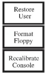
![graph TD A["Duplicate User"] --> B["Copy Floppy"] B --> C["Disable Screen"] C --> D["OK"]](/content/2026/06/1370664/images/74171f4b909c66591b9feb50b7b00ad47103ade55d8b73a2f5901cc5b9159fff.jpg)
Touch Pads
Backup User. This will backup the data, which relates to the User, on the hard disk to floppy disks. You will be prompted to remove each floppy disk when it is full and to insert the next floppy. If there is data already on a floppy you will be prompted to confirm that you wish to over-write the data on it.
Readability of backups may be checked on a PC, or you may use the verify facility which is offered after the backup process has finished.
Restore User. This restores data from floppy disks onto the hard disk.
Duplicate User. This copies the current User. The copy has the same name as the original name plus (dup) as a prefix.
Change Mix Disk. Allows you to change the drive to which Mixes are saved.
Format Floppy. You will be prompted to insert a floppy disk in the drive. You will be warned if the disk is already formatted, and you will have the option to continue or not.
Copy Floppy. This allows you to make a backup copy of a floppy disk. You will be prompted to insert the Source disk or to cancel. Assuming that you insert a source disk and press 'Continue', the contents of the disk will be read into RAM. Then the system will prompt you to insert the Target disk and to press 'Continue'. The copy of the Source disk which is currently held in RAM will then be copied onto the Target disk.
Shutdown Console. This writes the contents of RAM to disk, closes all of the open disk files and then prompts you to switch the console off.
Recalibrate Console. This recalibrates the Automated Faders' Laws. This Utility takes approximately five minutes per bank of 8 Faders to execute.
Disable Screen. This allows you to clean the surface of the screen without activating any touch-pads.
OK. Press the OK touch-pad to return to the User page.
Automated Mixing
Starting The Automation
Switching On
When the console is switched on the LCD display (the screen) will illuminate. The system will then execute several routines and checks, and it displays its progress on the screen.
If there is a system disk in the floppy drive, the automation will load the program from the floppy disk into RAM and will then run it. If you hold down the Setup button, within approximately 5 seconds of power on, the program will also be copied to the hard disk, and the previous version will be deleted from the hard disk: you will know if you have pressed Setup within the time allowed because its LED will light up.
If there is no floppy disk in the floppy drive, the automation will load the program from the hard disk into RAM and will then run it.
Automated Mixing
Whenever the console is powered up, and has successfully finished its self-checks, the following page is displayed.

The Mix Page
The most recently used Mix Pass will be displayed.
At this point the console is in manual mode. The Automated faders and switches may be moved at will.
In order to use Automated mixing you must press the MIX ON button on the Control Panel: the amber LED next to the button will glow to indicate that Automated Mixing is on.
At this point you have the choice of starting a new mix pass or of editing an existing one (if any exist at this time).
The following pages deal with each of these options in detail.
The Cue Points for a Mix are stored under the Title name: therefore if you change, add or delete Cue Points the old set of cues cannot be recalled even if you load an earlier mix pass which was done with the old Cue Point values. The following diagram shows this concept. Note that you do not need to use Cue Points to do a mix, they will, however, make the mix easier to do.

In the diagram above, the Title is shown as the piece of tape with which it is associated: the tape has 3 verses, each followed by the chorus. At the time that the first mix was done only 3 cues were used. The movement of one fader is shown against the mix. Suppose that the tape was stopped at the end of the first chorus: the dotted line running to the end of the title shows that the fader would stay in this position if the tape was later run for the whole of the title. Similarly, the dotted line to the left of the fader's movement indicates that the fader would go to this position if the tape were subsequently played from a position before the start of verse 1.
Now suppose that you wanted to start again with a new mix (mix 2). This time you run the whole tape and put in more Cue Points and edit one of the old ones. You also have different fader movements on the channel in question.
Finally, you decide that mix 1 shows more promise and you want to edit it. You can see from the final part of the diagram above that the old fader movements are reloaded but that the original Cue Points are not.
How To Insert Cue Points
Whilst the tape is running you may insert Cue Points at musically significant moments: this is done by pressing the TRANSFER button on the Control Panel. The mix automation does not need to be on to do this. It may be convenient therefore to run the tape through with the console in manual mode and put the required cues in. You may edit the cues later if they are, say, a few frames out.
The Automation will accept up to 50 Cue Points per Title. Before any mixing has been done for a Title there are 50 unused Cue Points listed. Every time you press the TRANSFER button a numbered cue is inserted into the list in timecode order. You may edit the cue name for convenience.
Automated Fader and Switch Modes
Each Automated Fader and the Switches can be in one of four modes, which are as follows:
Manual. The Fader or Switch operates normally as if it were not automated.
Read. Changes to the Fader or Switches which have previously been recorded against the Timecode are played back, i.e. the changes are read from the Automation.
Armed. This mode is the same as Read mode until you make a change, at which point the change is written into the Mix Data.
Write. The Fader position and Switch states are written into the Mix Data, writing over all previous Mix data.
The mode of a Fader or Switch is changed by pressing the appropriate mode switch, labelled SW for Switches and FDR for the Fader. Pressing the Mode switch causes the mode to be cycled through in the order shown in the following list.
The WR (Write) and RD (Read) LEDs indicate which mode the Fader and Switches are currently in. There are separate LEDs on each channel for Fader and Switches. The modes are indicated as follows:
RD WR
Manual: OFF OFF
Read: ON OFF
Armed: ON ON
Write: OFF ON
When timecode is running and mixing is selected, it is not possible to change mode to Manual.
The Faders are touch-sensitive, the Automation is able to detect when you are attempting to move them and it will turn off the drive to the motors to allow you to do this.
The following faders are Automated:
- Input Monitor Faders
- Master Output Fader.
All automated switches have independent modes, however the selected switches on a particular input strip all have the same mode, i.e. the mode which the LEDs are displaying. Switches are selected by holding down the SEL switch on a particular input strip, and then pressing the required switch. A selected switch is indicated by the adjacent amber LED. Once selected its mode may be changed by pressing the SW switch. Non-selected switches will be in the default mode which is stored via the Mode Setup page; if this default mode is Armed then changes may be added into the mix even though the switch is not selected. If the default mode is Read the non-selected switches, if pressed, will change to Manual for the rest of the Mix pass.
The following switches are Automated:
- Input strip: Aux1 On, Aux3 On, Channel Cut, Monitor Cut.
- Group/Stereo Input: Group Cut, Stereo Cut.
- Aux Master: Cut
- Foldback Master & Studio Output: FB Cut Switches
Group Assignments
Each of the Inputs may be assigned to one of the four Control Groups (see Group Assignments).
The Fader and Switch modes of all of the Inputs which are assigned to a particular Group may be changed by using the Group's FDR and SW buttons.
You may also use the Control Group Faders to add (or subtract) an offset (in dBs) to all of the Faders in the assigned Group.
Controlling the Faders and Switches
Before attempting to edit a Mix Pass it will be helpful if you understand the following differences between Fader and Switch positional-data storage.
Faders
The following diagram shows the effect of moving a fader which is in armed mode. The top trace shows the Fader's movement during the first Mix. The second trace shows what happens if the Fader is in Armed mode during the next mix, and you move it in order to edit its position. When you touch the Fader at the position shown the Fader will go into Write mode and the drive to its motor will be removed to allow you to move it freely. You then make the movements as shown and then release the Fader. When you release the Fader it will go back into Armed Mode and it will follow one of the two alternative traces: if Glideback is on, the Fader will move back to the position it had in the previous mix (the speed with which it moves back to its original position depends upon the Glide-rate setting); if Glideback is off the Fader position will be offset by the difference in level between the position when you released the Fader and its position in the previous mix.
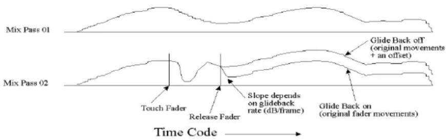
Switches
The Automation deals with switches differently to Faders, since only transitions (from On to Off and vice versa) are recorded by the automation: instantaneous values for the duration of the Mix are not recorded. This has implications when you want to edit switch settings within the Mix.
The top trace in the diagram below shows, by way of an example, the setting of a Cut switch as the Mix proceeds. Suppose that you wanted to make some adjustments to the time that the Cut switch is operated. In the diagram two changes are made, in both cases the dotted line show the original transitions, and the solid line shows the new transitions.
![graph TD A["Mix Pass 01"] --> B["Cut Off"] C["Mix Pass 02"] --> D["Cut Off"] E["Time Code"] --> F["Change may be made in Armed mode"] G["Time Code"] --> H["Put Switch into Write mode here"] I["Time Code"] --> J["Change must be made in Write mode"] K["Time Code"] --> L["Put switch into Armed or Read…](/content/2026/06/1370664/images/a6efdcaaace86e685ef7399ef20df170998bc0ed149ae64cf5101e1439b3181e.jpg)
The first change is easier to make for the reason that you are moving the event forward in time (i.e. earlier). Because of this you can put the switch into Armed mode at some time before the change is to be made and at the appropriate time press the Cut switch. Because it is still in Armed mode after the new event it will follow the next recorded event, i.e. the transition from On to Off.
The second change is more difficult because you are moving the event backwards in time (i.e. later). If the switch were to remain in Armed mode the old transition would still be replayed, all you could do would be to quickly turn it off again. The way to deal with this correctly is to put the switch into Write mode at some time before the required change (see diagram). The Automation will then overwrite the existing transitions with the transitions from the switch. You may then make the new transition at whatever time you wish. If there are more transitions which you want to keep you must put the switch back into Armed Mode, or Read mode, as soon as you have made the change.
As was explained in an earlier section, the selected Switches may not be put into different modes independently of each other. The selected switches (on a particular input strip) will all be in the same mode as each other, i.e. the mode which the LEDs are displaying. The non-selected switches will be in Read or Armed mode. It is therefore essential, when putting a switch into Write mode, that it is the only selected Switch on the input strip. Failure to do this will mean that you overwrite switch transitions on other switches.
Using Control Groups
There are four Control Groups. Each Mono Input Monitor may be assigned to one of the Control Groups at a time, or assigned to none of them.
To assign Mono Input Monitors to Control Groups proceed as follows:
- Press the GROUP ASSIGN button on the Automation Panel, the green LED will glow to indicate that the mode is active, and the Group Assign page will be displayed on the screen.
- Press the appropriate touch-pad for the particular Control Group you wish to assign Mono Inputs to.
Press the SEL switch on the Mono Inputs you wish to assign. The appropriate Control Group Assign LED on the Mono Input will glow.
Switch and Fader Modes
The mode of the Switches or Faders on all of the assigned Mono Inputs is changed by pressing the appropriate mode switch, labelled SW for Switches and FDR for the Fader. Pressing the Mode switch causes the mode to be cycled through in the following sequence: Manual, Read, Armed and Write. Note that Manual Mode is not available whilst the Tape is running.
Note: the mode of faders and switches of individual Mono Inputs may still be changed by using the mode switches on individual Mono Inputs. However, any subsequent changes made from the Control Group switches will over-ride individual changes.
The WR (Write) and RD (Read) LEDs indicate which mode the Fader and Switches are currently in. There are separate LEDs for Faders and Switches. The modes are indicated as follows:
RD WR
Manual: OFF OFF
Read: ON OFF
Armed: ON ON
Write: OFF ON
Note: the mode displayed by the Switches LEDs only applies to those switches on Mono Inputs which have been selected (the amber LED next to the switch will be on to indicate that a particular switch has been selected).
Control Group Fader
The Fader allows you to move all of the Mono Input Monitor Faders which are assigned to the Control Group in question. Any offset in positions are added to the Monitor faders movements.
One particular advantage of using Control Groups to move Monitor faders is where, for example, you have set up fairly complex fader movements during a musical piece but then decide that they are 5dB too low. By using a Control Group it is very easy to add an offset to all of the faders in question, while still retaining all the nuances of fader movements. Compare this with what happens if you individually move a Monitor fader in Armed or Write mode: i.e. the original fader movements are
overwritten with new ones.
The Monitor faders will only follow the Control Group faders when the Monitor faders are in Read, Write or Armed mode. If the Monitor faders are switched into Manual mode, and the Control Group fader is moved, and then the Monitor faders are switched into one of the three active modes they will immediately move to their new positions: i.e. switching them into Manual Mode does not change the offset between them and the Control Group's fader position.
The use of the Control Group faders is best explained by use of the examples given below.
• Example 1
Suppose that a Mono Input fader is at 0dB at the time that it is assigned to a Control Group. The Control Group's fader is also at 0dB. If the Control Group's fader is moved then the Monitor fader will follow it (provided it is not in Manual mode).
• Example 2
Suppose now that you put the Control Group's fader back to the 0dB position. Suppose also that the Mono Input Monitor fader is in Write or Armed mode and that you move it individually to, say, -10dB. If you then move the Control Group's fader the Monitor fader will follow it but with a -10dB offset.
Note what happens when the Control Group's fader is moved to -∞ : the Monitor fader also goes to -∞ , but when the Control Group's fader is moved back up again the -10dB offset is still in operation.
• Example 3
Suppose again that you put the Control Group's fader back to the 0dB position. Also suppose that the Mono Input Monitor fader is in Write or Armed mode and that you move it individually to, say, +10dB. If you then move the Control Group's fader the Monitor fader will follow it but with a +10dB offset.
Again note what happens when the Control Group's fader is moved to -∞ : the Monitor fader also goes to -∞ , but when the Control Group's fader is moved back up again the +10dB offset is still in operation.
Also notice what happens as the Control Group's fader moves towards the +10dB mark (top of its travel): the Monitor will already have reached the top, but when the Control Group's fader is moved back down again the +10dB offset is still in operation.
• Example 4
In this final example suppose that the Control Group's fader is at, or near, -∞ . A Monitor fader is at, say -10dB. A small movement of the Control Group's fader will cause large movements on the Monitor fader in question. You will notice from this that you will not have very fine control when a large offset exists. To regain this fine control you may use the Fader Disengage facility described in the next paragraph.
Fader Disengage
If you have run out of fader travel, or you no longer have fine control as described in example 4 above, you may temporarily disengage the Control Group faders as follows: press and hold the SEL button on the appropriate Control Group panel, and move the fader to a new position, then release the SEL button.
Moving the Tape
There are a number of tools provided to enable you to move the tape. Note, however, that they all depend upon your tape machine being able to accept remote control commands.
They are as follows:
- The Remote Control buttons on the Control Panel, i.e. Fast Forward, Fast Rewind, Play, Stop and Record.
- The Jog Wheel. If you press the SEARCH button the Jog/Shuttle Wheel will be in Shuttle mode (the green LED will be on continuously to indicate this) the tape machine may be fast forwarded or rewound by moving the Jog/Shuttle wheel.
The Jog/Shuttle wheel may be put into Jog mode by pushing it down and then releasing it (the green LED will be flashing to indicate this). The tape may then be jogged frame-by-frame.
- Assuming that you have set some Cue Points, you will be able to move the tape to any of these Cue Points by positioning the required one in the Cursor Line and then touching the Cursor Line.
- The four Cue Point Markers may also be used. The markers are LOCATE0, LOCATE1, Drop In and Drop Out. These are assigned by locating the required Cue Point in the Cursor Line and then pressing STORE and the required Cue Point Marker button. Once these Markers are assigned you may move the tape to their Cue Points by pressing the appropriate Marker buttons.
Those Cue Points which have a Marker assigned to them indicate this by having the following characters to the left of them on the display:
L0 = LOCATE0
L1 = LOCATE1
D1 = Drop In
DO = Drop Out.
- Auto Play. If Auto Play is on, and you then press any of the Cue Point Marker buttons, the tape will wind to the appropriate Cue Point and then will play.
- Auto Return. If Auto Return is on, the tape will stop when it gets to L1 (plus any post-roll value). It will then rewind to L0 (minus any pre-roll value). If L0 is after L1, Auto Return cannot be selected. When the tape starts to rewind the faders and Switches will go into whichever mode has been selected in the Modes Set-up page.
Mixing a New Title
When the Mix Page for a new Title is selected, the Screen Title will read, 'Mix: No Mixes'. The first mix pass number will only be allocated when the tape has been run and then stopped again.
The First Run-Through
The purpose of the first run-through is to get the fader positions roughly correct. The following steps should be performed:
- Press the MIX ON button.
- The Faders and Switches will automatically be put into Write mode ready for the first pass.
- Position and then play the tape from the start. You may freely move the Monitor and Master Faders: their positions will be written to the mix pass. Note that as soon as you press PLAY the ABORT LED will start to flash: this indicates that new fader/switch data is being stored. If you wish to discard this Mix Pass press the ABORT button before you press the STOP button. If you do press the ABORT button, its LED will turn on all the time: this indicates that the new data will not be stored.
- Stop the tape at the end of the end of the musical piece.
If you have not aborted this Mix Pass the Screen Title will now read, 'Mix: New Mix Pass 01'.
The Fader status LEDs will now indicate either ARMED (Both LEDs on) or READ (green LED on): the actual setting is determined by the appropriate setting in the Modes page.
At this stage you may edit the current Mix Pass, or you may start again with a new Mix Pass.
Editing an Existing Mix
Assuming that you have a Mix Pass (by default it will be named, 'New Mix Pass 01'), you may now edit it.
A convenient way of working is to assign the Cue0 Marker to the first Cue Point, and Cue1 to the last Cue Point. You may also wish to turn the Auto Return mode on.
Proceed as follows:
- Press LOCATE0 to rewind tape.
- Ensure Mix On mode is active.
- Put into Read mode, those faders and switches which you do not want to alter.
- Put into Armed (or Write) mode those faders and switches which you do want to alter.
- Press PLAY.
You may now make changes to the Mix. Bear in mind the way in which the Fader and Switch transition data is recorded by the Automation.
When the tape stops (and assuming that you have not Aborted the Pass) the New Mix Pass will be saved. The way in which the default Mix Names are assigned is explained below.
Mix Names
Action PerformedName of Mix PassNotes when the tape stops.
Do the first run through New Mix Pass 01 (The first new mix pass) Run mix1 and do changes Untitled Mix Pass 02 (The edited version of 01) Run mix2 and do changes Untitled Mix Pass 03 (The edited version of 02) Press New Mix & do run through New Mix Pass 04 (The second new mix pass) Run mix4 and do changes Untitled Mix Pass 05 (The edited version of 04) Run mix5 and do changes Untitled Mix Pass 06 (The edited version of 05) Reload Mix Pass 03 & do changes Untitled Mix Pass 07 (The edited version of 03) Run mix7 and do changes Untitled Mix Pass 08 (The edited version of 07) Run mix8 and do changes Untitled Mix Pass 09 (The edited version of 08)
You may see from the above table that it could become very difficult to keep track of the evolution of a Mix, especially if you do more than 50 passes and the software starts to wrap-around the mix names (i.e. it overwrites Mix 01 with a new version and so on). It is suggested that you make use of the facility to edit Mix names and also the facility to protect mixes against being overwritten on wrap-around.
Starting a New Mix
If you wish to abandon a series of Mix Passes, and to start again, press the New Mix Touch-pad on the Mix page.
The following will then happen:
- The Switches and Faders will go into Write Mode.
- The Mix Title will become, 'New Mix Pass' followed by the current Mix number (remember that the next Mix Number is only assigned when the tape stops at the end of a Mix Pass).
After positioning the tape to the correct place, press Start. You will then have a New Mix Pass with no previously recorded movements to interfere with the Mix that you are about to begin.
Note: the old Mix Passes will still be stored on disk and you may reload them later (provided that they have not been overwritten by wrap around versions).
Drop-in/Drop-out During the Original Track-laying
If the tape machine you are using supports this function you may drop-in/drop-out sections of tracks.
The principle of operation is that you set up a Cue point at the start of the section to be dropped-in/dropped-out and another at the end of the section. Then set the DROP IN and DROP OUT markers to these cue points.
Preview Mode
Setting the automation to Preview mode allows you to practice the drop-in/drop-out without recording to tape.
PREVIEW is selected by pressing the PREVIEW button, a LED above the switch glows to indicate selection. It is deselected by pressing the PREVIEW button again.
The tape machine will not drop into record at the Drop |n point when RECORD PREVIEW is selected; Instead, the inputs of the channels which would have been recorded are monitored between the Drop |n and Drop Out points. This allows the material to be previewed.
The Repro. head on the tape machine should be selected when RECORD PREVIEW is selected. This is done automatically on supported tape machines.
Record Mode
Record Enable is selected by pressing the RECORD ENABLE button, a LED above the switch glows to indicate selection. It is deselected by pressing the RECORD ENABLE button again.
The Drop |n and Drop Out points become active when RECORD ENABLE is selected, i.e. the enabled tracks on the tape machine will drop into record when the tape plays through, or starts from, the Drop |n point. Similarly, the tracks will drop out of record when the tape plays through the Drop Out point.
Note: the Sync. head on the tape machine should be selected when RECORD ENABLE is selected. This is done automatically on supported tape machines.
Track Selection
You may chose which tracks to drop-in/drop-out via the Record Enable page, or by pressing the SEL switch on the required channel when Record Enable is active.
Review Mode
Review allows you to do a drop-in loop, i.e. a loop using Auto Return and Auto Play between the Drop-in and Drop-out points, without being in Preview mode or in Record Enable mode. Review mode is entered when the PREVIEW button is pressed twice in succession, and is indicated by the Preview LED flashing.
Record Loops
A Record Loop is set up by setting the Drop-in and Drop-out points, and selecting Auto Play and Auto Return with appropriate pre-roll and post-roll times.
Select Preview and Arm the required tracks. Initiate the loop by pressing the Drop-in Locate button. The machine will then start looping between the Drop-in/out points
(with pre/post-roll), and will switch over to input monitoring at the Drop-in/out points (because it is in Preview mode). When you want to record, press Record Enable: on the next pass, the Armed tracks will drop-in to record at the Drop-in point.
After recording, the final pass will automatically switch to Review mode so that you may listen to the material. The tape will then stop.
Specifications
Specifications
Frequency Response
Any input to any output 20Hz - 20kHz +0/-0.5dB
Total Harmonic Distortion
(All Measurements at +20dBu)
Line In to Tape Send Less than 0.002% @ 1kHz
Line In to Mix Out Less than 0.02% @ 1kHz
Tape Return to Mix Out Less than 0.02% @ 1kHz
Noise
(22Hz - 22kHz bandwidth, unweighted)
Mic Input EIN Less than -127dBu (200 ohm source)
Tape Send noise Less than -85dBu
Group Output Noise Less than -80dBu (32 ch routed)
Mix Output Noise Less than -75dBu (32 ch routed)
CMRR
Mic Input (maximum gain) Greater than 90dB
Line Input (unity gain) Greater than 55dB
Crosstalk
(All measurements at 1kHz)
Input Channel Muting Greater than 95dB
Input Channel Fader isolation Greater than 70dB
Mix Routing isolation Greater than 90dB
Group Routing isolation Greater than 90db
Group to Group crosstalk less than -75dB
Group to Mix crosstalk Less than -80dB
Input and Output Impedances
Mic Input 2k ohms balanced
Line Input Greater than 10k ohms balanced
Insert Send Less than 75ohms, gnd comp.
Insert Return Greater than 10k ohms unbalanced
Tape Send Less than 75ohms, gnd comp.
Tape Return (+4dBu) Greater than 20k ohms balanced) (-10dBv) Greater than 10k ohms balanced)
Mix/Control Room Outputs Less than 75ohms, gnd comp.
Video Sync 75 Ohms
Input/Output Capability
Mic Maximum Input Level +10dBu
Line Maximum Input Level +30dBu
Tape Send Output Level +21dBu into 600 ohms
Tape Return Input Level +26dBu
Mix/Control Room Outputs +21dBu into 600 ohms
Headphone Output +20dBu into 600 ohms
50mW into 8 ohms
Input/Output Levels
Mic Input Sensitivity (XLR) -10dBu to -60dBu
Line Input Sensitivity (1/4" jack) +10dBu to -40dBu
Insert Send/Return -2dBu nominal
Tape Send/Return +4dBV nominal (selectable)
Mix/Control Room Outputs +4dBu for 0VU
Video Sync 1V pk-pk
Notes For Machine Control for Software Release 7.05
Notes for machine control
Protocol Support
At the time of writing (May 1995) the following tape machines/protocols are supported:
Machine/Protocol Timecode source
MIDI Timecode master internal
MIDI MT(Tin(ModilFirchenCode)
Fostex MTG series
Fostex MTR series
Fostex RD-8 LTC (Using Midi Machine Control)
Midi Machine Control MTC
Midi Machine Control LTC (S.M.P.T.E)
MMC Open Loop MTC
LTC Timecode Master LTC
LTC Timecode Client LTC
Akai DR4 LTC & MTC
Alesis ADAT AI-2
Alesis BRC MTC
Sony 9-Pin Compatible Machines, which include the following record types:
ATR Type I Record LTC
ATR Type II Record LTC
P2 AUTO VTR LTC
P2 No Record LTC
P2 Type I Record LTC
P2 Type II Record LTC
D2 Type III Record LTC
Sony UVW 1800P LTC
Sony UVW 1800P / TascamDA-88 LTC
Tascam DA-88 LTC
Tascam DA-88 MTC
All Trademarks acknowledged.
Timecode Support
The console will display the last timecode value sent by the tape machine. This means that, for some machines, when you rewind the tape the displayed timecode will be that at which the tape was stopped. This will be displayed until the tape is played again, at which point the display will update to the new value being sent.
To cope with tape dropout the SMPTE reader 'flywheels' for ten frames after which the timecode stops.
Control Button Support
To provide feedback to the console transport control buttons the tape machine should support 'tally' messages (i.e., feedback from the tape machine of its status). If this is not provided the console tries to interpret any timecode being sent to produce these 'tally' messages internally.
MIDI timecode master
The DC2020 uses its own internal clock as a timecode reference for mixing. It also sends out MIDI timecode. This mode would normally be used with sequencers which can chase to MTC.
Transport Controls
Control timecode sent out by the DC2020.
Locate To Timecode
Supported. (assuming all other devices will chase to MTC)
Record Enable/Rehearse
Not supported.
Jog/Shuttle
Shuttle not supported (Use FF or REW).
Jog mode supported.
Setup Notes
Connect MIDI cable from DC2020 to sequencers etc.
MIDI timecode client
The Automation clients to incoming MIDI Timecode. The transport buttons on the console indicate whether timecode is running, stopped etc. The console transport controls have no effect on the tape machine.
Transport Controls
Display only, by using timecode values returned by the tape machine.
Setup Notes
Connect MIDI cable from external MIDI Timecode source to console.
MIDI machine control (MTC)
This allows the DC2020 to work with a tape machine which can be controlled using the generic MIDI Machine Control (MMC) protocol and which also sends the timecode as MIDI Timecode (MTC) on the same MIDI output as the MMC tallies.
Transport Controls
All supported, machine required to send back tallies
Locate To Timecode
Supported.
Record Enable/Rehearse
Supported
Jog/Shuttle
Not supported
Setup Notes
See tape machine manual
Other Notes
Closed loop system required. Open loop users may wish to try the Alesis driver (Alesis ADAT AI-2).
MIDI machine control with LTC
This allows the DC2020 to work with a tape machine which can be controlled using the generic MIDI Machine Control (MMC) protocol and which sends the timecode as SMPTE Longitudinal Timecode (LTC).
Transport Controls
All supported, machine required to send back tallies
Locate To Timecode
Supported.
Record Enable/Rehearse
Supported
Jog/Shuttle
Not supported
Setup Notes
Connect SMPTE IN on the DC2020 to the Timecode Output of the Tape Machine. Connect MIDI cables from the Tape Machine MIDI Controller to the DC2020 MIDI IN.
Other Notes
Closed loop system required.
LTC timecode (client)
The Automation clients to incoming SMPTE Timecode.
This mode would be used for a tape machine which has no interface for the DC2020 to control it, but which has SMPTE Timecode recorded on one track of the Tape Machine.
Transport Controls
Display only, by using timecode values returned by the tape machine. The transport buttons on the console indicate whether timecode is running, stopped etc.
Setup Notes
Connect tape machine SMPTE signal to SMPTE IN on the DC2020.
Additional Hardware Required
IB-113M-V3.0 MIDI Interface Board
IB-112T-V3.0 SMPTE/EBU Timecode Interface Board (optional)
Transport Controls
All supported, except record.
Locate To Timecode
Supported.
Record Enable/Rehearse
Not supported by the DR4
Jog/Shuttle
Not supported by the DR4
Setup Notes
See the DR4 user documentation.
![graph TD A["AKAI DR4"] --> B["MIDI INSMPTEND OUT"] A --> C["MIDI OUTSMPTEND IN"] B --> D["Device Array"] C --> D D --> E["Display Grid"] style A fill:#f9f,stroke:#333 style B fill:#ccf,stroke:#333 style C fill:#cfc,stroke:#333](/content/2026/06/1370664/images/972877359e09d3e3899ffa11f7af0fd0743220060d6d00403ec3c58267f56a13.jpg)
Additional Hardware Required
AI-2 Synchronisation Interface
Transport Controls
All supported, except record. Display tallies created from MTC fed to the DC2020.
Locate To Timecode
Supported.
Record Enable/Rehearse
Not supported by the Al-2
Jog/Shuttle
Not supported by the Al-2
Setup Notes
The following parameters should be set-up on the AI-2 Menus.
Menu Submenu Option
Control Mode Auto
MIDI MTC ON
REFERENCE Input IntFix
REFERENCE GEN Play/Wind
REFERENCE GEN STILL ON
The following diagram shows how to connect the MIDI and sync cables.
Put the AI-2 on-line by pressing its ON-LINE switch.
Other Notes
Open loop control system, uses MMC to control tape machine, may be useful on other 'dumb' machines.
![graph TD A["AT-2"] --> B["SYNC OUT"] B --> C["SYNC IN"] C --> D["MASTER ADAT"] D --> E["SYNC OUT"] E --> F["CLIENT ADAT"] F --> G["MIDI IN"] G --> H["MIDI OUT"] H --> I["Output"]](/content/2026/06/1370664/images/9182e6e7cb23b54127188af787b001b22fe9f67394a213109c6de2f17ff63116.jpg)
Alesis BRC (MTC)
Transport Controls
All supported, BRC sends back tallies
Locate to timecode
Supported
Record Enable/Rehearse
Supported.
Jog/Shuttle
This function is not supported by Alesis BRC.
Setup Notes
Use the MIDI/UTIL button on the BRC to select page 1 on the LCD display
[1. MIDI Echo]
[ OFF ] Use the keys to select option to OFF.
Select page 8
[8. Output Rew/FF]
[ SMPTE & MTC ON ] Use the ↑↓ keys to select option to ON.
Select page 9
[9. Sysex Output]
[ Enable ] Use the keys to select option to Enable.
Enable the timecode output using the GEN SYNC button on the BRC.
A10516 BRC
Alesis BRC


Fostex G series (MIDI)
Additional Hardware Required
G series synchroniser card required, to be fitted to tape machine (Fostex Part no. 8330).
Transport Controls
All supported, machine sends back tallies.
Locate To Timecode
Supported.
Record Enable/Rehearse
Supported.
Jog/Shuttle
Not supported by Fostex G series machines.
Setup Notes
The following procedure should be followed on the front panel of the G24 to set-up the parameters on the synchroniser card.
Hold down RCL, while held down press STO
Type 60, use "." to change to SIO MIDI.
Press STO.
Hold down RCL, while held down press STO
Type 63. Type 01.
Press STO.
Hold down RCL, while held down press STO
Type 64, use "." to change to ADFr oF.
Press STO.
Hold down RCL, while held down press STO
Type 65, use "." to change to change to Chuc of F.
Press STO.
Don't forget to connect timecode output from the tape to CODE IN. See diagram below.
![graph TD A["FocIOX-0 Series"] --> B["Track Out"] B --> C["TIME CODE IN"] C --> D["MIDI OUT"] D --> E["Output 1"] D --> F["Output 2"] D --> G["Output 3"]](/content/2026/06/1370664/images/ec636d1fa99fd0d7aa1968dc7b8b66cfe64e69753ff05f8bc7b2be9e87f1c947.jpg)
Fostex R series (MIDI)
Additional Hardware Required
Fostex MTC-1 Interface (Software version greater than 1.3 required for full functionality)
Transport Controls
All supported, machine sends back tallies
Locate To Timecode
Supported.
Record Enable/Rehearse
Supported. Possible problem with old Fostex exclusive messages on machines earlier than rom revision 1.4.
Jog/Shuttle
Not supported by Fostex R series machines.
Setup Notes
Remember to connect Timecode from tape track to MTC1. See diagram below.
Set dipswitch on back to all zeros except switches 8 & 6.
![graph TD A["Foster-R Series"] --> B["MIDI IN"] A --> C["MIDI OUT"] A --> D["TIME CODE TRACK OUT"] A --> E["MIDI OUT"] A --> F["MIDI IN"]](/content/2026/06/1370664/images/2f23414b5da826187adf533b7cdffbc555e04567a02ac08622288438afa6e1c8.jpg)
Fostex RD-8 (LTC)(Midi Machine Control)
Transport Controls
All Supported, Tallies generated by LTC.
Locate to Timecode
Supported
Record Enable/Rehearse
This function is supported, but automatic drop-ins are not supported by the Fostex RD-8 using MMC. (RD-8 Software version 1.04).
Jog/Shuttle
This function is not supported by Fostex RD-8.
Setup Notes
Using the buttons on the Fostex RD-8 the following setup is required.
Press button marked Edit Data followed by Remote/Local then F3. This will select Remote In: Midi.
Deselect Edit Data
Using the Remote/Local Button select both modes (RED and GREEN LED on).
Press Home button to access the main menu. Using the Next button select main menu 3.
Press F3 to select TCFrame. If the Tape is striped with Timecode then Press or To select TCOut FR TAPE. If the tape has no Timecode on it then Press or To select TCOut FR 24, 25, 29.97df or 30.
Press Home button to access main menu. Using the Next button select main menu 4.
Press F1 to select TCRew. Press or To select TC REW/FWD to ON.
Press Home to select Main menu 4. Using the Next button select main menu 6.
Select MMCOut by pressing F3. Press or To select MMC Output: to ON.

Sony 9-pin Compatible Machines
The following machine types may be selected from the Tape Machine Selection page:
- ATR type 1 Record
- ATR Type II Record
• P2 AUTO VTR
• P2 No Record
• P2 Type I Record
• P2 Type II Record
• D2 Type III Record
Depending upon the type selected, one of the following pages will appear on the Touch-screen.
Note: to access these psges you must exit SETUP and then access RECORD ENABLE via the TITLE CONFIG page.
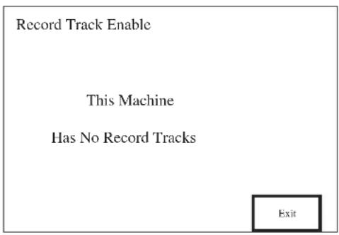
![graph TD A["VTR I Record Enable"] --> B["Insert"] A --> C["Assemble Video"] A --> D["Audio CII 1"] A --> E["Audio CII 2"] A --> F["Timecode"] A --> G["Disable all"] A --> H["OK"]](/content/2026/06/1370664/images/b0a923051020f833a456fc47c88443900a2d456cabfb4f0132e90c66e4431ddf.jpg)
![graph TD A["VTR II Record Enable"] --> B["Insert"] A --> C["Assemble Video"] A --> D["Audio CH 1"] A --> E["Audio CH 2"] A --> F["Digital Audio 1"] A --> G["Digital Audio 2"] A --> H["Timecode"] A --> I["Digital Audio 3"] A --> J["Digital Audio 4"] A --> K["Disable all"] A --> L["OK"]](/content/2026/06/1370664/images/077dc2bb606f57e4e0d0ad7e2519d7d5cec2b349efa3aa10a04d34e32ad09b1a.jpg)
![graph TD A["VTR II Record Enable"] --> B["Insert"] A --> C["Assemble Video"] A --> D["Audio CII 1"] A --> E["Audio CII 2"] A --> F["Digital Audio 1"] A --> G["Digital Audio 2"] A --> H["Timecode"] A --> I["Disable all"] A --> J["OK"]](/content/2026/06/1370664/images/009e304f890fa15c5ad82119de1ee2008a3c89bc24f2e9674decdcffe22730ef.jpg)
![graph TD A["Insert"] --> B["Assemble"] C["Audio CH 1"] --> D["Audio CH 2"] E["Disable all"] --> F["Audio Tracks"] G["OK"] --> H["Timecode"]](/content/2026/06/1370664/images/3acc51fcc2b7f095712e2f4adcb077106e48e43c71e3342a02aac755752c2dd4.jpg)
Touch-Pads
Most of the touch-pads are self explanatory in that they enable various tape tracks. The enabled ones are shown in reverse video (white text in a black pad).
The Insert and Assemble touch pads are mutually exclusive, and they may both be off.
Additional hardware Required
DC2020 to Sony 9 Pin interface cable
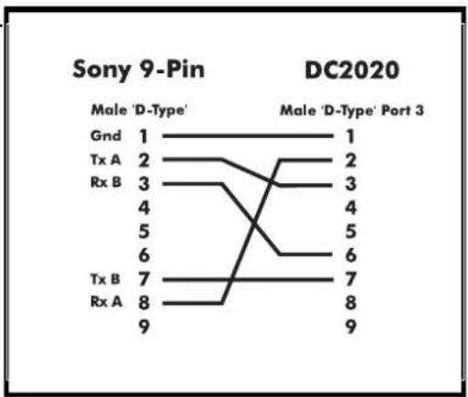
Transport Controls
Supported.
Locate to Timecode
Supported.
Record Enable/Rehearse
Not supported by DC2020
Jog/Shuttle
Supported.
Setup Notes
The Sony 9p machine must be set to remote.(9 pin remote).

On selecting this mode, the Tascam DA-88 is put into chase mode and will chase in-coming timecode. The timecode from the Sony VTR is linked to both the timecode input of the DA-88 and the SMPTE in of the DC2020. In this configuration the DC2020 sends all transport command to the Sony video machine, but sends record command and the track record enables to the Tascam DA-88.
Additional Hardware Required
SY-88 Card fitted to DA-88.
DC2020 to Sony 9 Pin interface cable.

Transport Controls
Supported.
Locate to Timecode
Supported.
Record Enable/Rehearse
Record commands not sent to Sony. Command routed to Tascam DA-88.
Jog/Shuttle
Supported.
Setup Notes
For Tascam DA-88 see [TASCAM DA-88 (MTC)]
Sony UWV 1800p (or any Sony 9p machine) must be set to remote.(9 pin remote).
![graph TD A["Sony UVW 1800P"] --> B["9 Pin Remote"] B --> C["PORT 3"] C --> D["Timecode out"] D --> E["Timecode In"] E --> F["MIDI IN"] F --> G["MIDI OUT"] G --> H["Tascam DA-88"] H --> I["9 Pin Remote"] I --> J["Timecode out"] J --> K["Timecode In"] K --> L["MIDI IN"] L --> M["MIDI OUT"] M --> N["9…](/content/2026/06/1370664/images/3fd767675781401f3d8ac16469a7564bb0352fbf733545909716efe6678a017e.jpg)
Additional Hardware Required
SY-88 card fitted to DA-88.
Transport Controls
All supported, machine sends back tallies
Locate To Timecode
Supported.
Record Enable/Rehearse
Only supported on Master machine: the Tascam SY88 card currently only supports a single tape machine for Record Enable/Rehearse, therefore client machines require manual intervention.
Jog/Shuttle
Not supported by the DA-88 with its current software.
Setup Notes
TIMECODE OUT from the DA-88 should be connected to SMPTE IN on the DC2020. See the diagram below.
Tapes must be formatted before use: this puts ABS-time onto the tape.
You may set the DA-88 to output timecode using the ABS -time or you may put a timecode signal on the tape, in addition to the ABS-time, and use that instead.
Care must be taken in setting up timecode on the DA-88. There are two menus which need to be set correctly. The ABS menu must be set to timecode(P.in = tc) (even if there is no time code on the tape: the locate function will not work otherwise), and the TC menu must be set to whichever code you are going to use (t.out = ABS or t.out = tc). See the Tascam DA-88 and SY-88 manuals for more details.
![graph TD A["Taccam DA-88 (LTC)"] --> B["MASTER DA-88"] A --> C["CLIENT DA-88"] B --> D["MIDI IN"] B --> E["MIDI OUT"] B --> F["TIME CODE OUT"] B --> G["SYNC OUT"] B --> H["SYNC IN"] C --> I["MIDI IN"] C --> J["SMPTE IN"] C --> K["MIDI OUT"]](/content/2026/06/1370664/images/a3f17fb1739bea12be67c1a1b6a0bbe219efb9defdfac90d591a3f7686d8f9b3.jpg)
Additional Hardware required
SY-88 Card fitted to DA-88 (software version 2.03 or better)
Transport Controls
All supported, machine sends back tallies
Locate to Timecode
Supported.
Record Enable/Rehearse
Tascam SY88 card currently only supports a single machine for record Enable/Rehearse, using the Midi machine Control protocol.
Jog/Shuttle
This Function is not supported by Tascam DA-88 via MMC (midi machine control).
Setup Notes
Tape must be formatted before use: this puts ABS-time onto the tape.
SY-88 Switch S1 #2: MIDI/9 PIN set to MIDI 0.
You may set the DA-88 to output timecode using the ABS-time or you may put a timecode signal on the tape, in addition to the ABS-time, and use that instead.
Care must be taken in setting up timecode on the DA-88. There are two menus that need to be set correctly. The ABS menu must be set to (P. In = tc)(even if there is no timecode on the tape: the locate function will not work otherwise), and the TC menu must be set to whichever code you are going to use (t. Out = ABS or t. Out = tc). See Tascam DA-88 and SY-88 Manual for more details.

Additional Hardware Required
SY-88 Card fitted to DA-88
(Software version 2,03 or better)
DC2020 to Sony 9-pin interface cable.
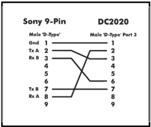
Transport Controls
All supported, machine sends back tallies.
Locate To Timecode
Supported.
Record Enable/Rehearse
This function is supported by DC2020.
Jog/Shuttle
Supported.
Setup Notes
Tape must be formatted before use: this puts ABS-time onto the tape.
SY-88 Switch S1 #2: MIDI/9 PIN set to 9 PIN 1.
You may set the DA-88 to output timecode using the ABS-time or you may put a timecode signal on the tape, in addition to the ABS-time, and use that instead.
Care must be taken in setting up timecode on the DA-88. There are two menus that need to be set correctly. The ABS menu must be set to (P.in = tc)(even if there is no timecode on the tape: the locate function will not work otherwise), and the TC menu must be set to whichever code you are going to use (t.out = ABS or t.out = Tc). See Tascam DA-88 and SY-88 Manual for more details.
![graph TD A["Tascam DA-88"] --> B["Timecode outRS-422"] B --> C["PORT 3"] B --> D["SMPTE IN"]](/content/2026/06/1370664/images/b33b0e55b8a12c13a570bbc17fae1f1919e998c0e494e104c9d30aa8bbcace67.jpg)
- TABLE OF CONTENTS
- INTRODUCTION 1.1
- INSTALLATION 2.1
- BLOCK DIAGRAMS 3.1
- FUNCTIONAL DESCRIPTIONS 4.1
- MONO INPUTS 4.3
- GROUP/STEREO INPUT 4.11
- AUXILIARY MASTER 4.15
- STUDIO OUTPUTS & FB MASTERS 4.19
- OSCILLATOR & TALKBACK PANEL 4.23
- CONTROL GROUPS 4.27
- STEREO MASTER 4.31
- CONTROL-ROOM PHONES AND SPEAKERS 4.35
- PATCHBAY 4.39
- AUTOMATION GUIDE 4.47
- INTRODUCTION 4.49
- PROJECT MANAGEMENT 4.55
- THE AUTOMATION PAGES 4.61
- AUTOMATED MIXING 4.113
- SPECIFICATIONS 5.1
- APPENDICES
- NOTES FOR MACHINE CONTROL FOR SOFTWARE RELEASE 7.00 A.1
- DC2020 ERROR MESSAGES B.1
- DC2020 PRINTER PORT C.1
- DC2020 DIAGNOSTICS DISK D.1
- INTRODUCTION
- OVERVIEW
- TYPICAL-USE ENVIRONMENT
- INSTALLATION
- ASSEMBLING THE CONSOLE STAND
- PRECAUTIONS AND SAFETY INSTRUCTIONS
- GENERAL PRECAUTIONS
- HANDLING AND TRANSPORT
- POWER SUPPLIES & CABLES
- WARNING
- SIGNAL LEVELS
- CAUTION
- WIRING CONVENTIONS
- DIN CONNECTORS
- D-TYPE CONNECTORS
- BNC CONNECTOR
- CONNECTING THE DC2020 TO A MAC OR TO A PC
- DC2020 TO MAC CONNECTION
- DC2020 TO PC CONNECTION
- INSTALLING THE MAC OR PC EMULATION SOFTWARE
- INSTALLING THE DC2020 EMULATION SOFTWARE
- DC FOR MACINTOSH
- DC FOR WINDOWS
- IMPORTANT
- PATCHBAY EDAC PIN IDENTIFICATION CHART AND PINOUTS
- TAPE TRACKS 1-8
- TAPE TRACKS 9-16
- TAPE TRACKS 17-24
- FUNCTIONAL DESCRIPTIONS
- MONO INPUTS
- MONO INPUT
- INPUT CONTROL SECTION
- TAPE RETURN
- EQ
- AUXILIARY CONTROLS
- FOLDBACK
- PAN CONTROL
- ROUTING
- CHANNEL PATH
- MONITOR PATH
- AUTOMATED FADER AND SWITCH MODES
- RD WR
- THE SOLO SYSTEM
- SOLO
- SOLO IN PLACE
- METERS
- REAR CONNECTOR PANEL
- MICROPHONE INPUT - FEMALE XLR
- LINE INPUT - 3-POLE JACK
- INSERT
- TAPE SEND
- GROUP/STEREO INPUT
- STEREO INPUT
- GROUP
- REAR CONNECTOR PANEL (NON-PATCHBAY ONLY)
- GROUPS
- GROUP INSERTS
- GROUP OUTPUTS - 3-POLE JACK
- AUXILIARY MASTER
- AUXILIARY 1
- AUXILIARY 2
- AUXILIARY 3
- AUXILIARY 4
- AUX OUT 1 TO AUX OUT 4 - 3-POLE JACK
- STUDIO OUTPUTS & FB MASTERS
- STUDIO OUTPUTS & FOLDBACK MASTERS
- STUDIO OUTPUTS
- FOLDBACK MASTERS
- SIGNALS FROM INPUT MODULES
- SIGNALS FROM STEREO INPUT MODULES
- FB1
- FB2
- STUDIO PHONES L
- STUDIO PHONES R
- STUDIO SPEAKERS L
- STUDIO SPEAKERS R
- OSCILLATOR & TALKBACK PANEL
- OSCILLATOR AND TALKBACK PANEL
- POWER INDICATORS
- OSCILLATOR
- TALKBACK
- CONTROL GROUPS
- CHANNEL
- MONITOR
- FADER DISENGAGE
- SWITCH AND FADER MODES
- FADER
- STEREO MASTER
- GLOBAL MODE CHANGES
- CONTROL OF MASTER PANEL SWITCH MODES
- CONTROL-ROOM PHONES AND SPEAKERS
- CONTROL-ROOM SOURCE
- INPUT REAR CONNECTOR PANEL (NON-PATCHBAY ONLY) 2
- OUTPUT REAR CONNECTOR PANEL (NON-PATCHBAY ONLY) THE
- PATCHBAY
- PATCHBAY FASCIA
- PATCHBAY WIRING
- LINE INPUTS 25-40
- GROUP OUTPUTS
- SMPTE TIMECODE
- STEREO INPUTS
- AUX OUTPUTS
- FOLDBACK OUTPUTS
- STUDIO PHONES
- STUDIO SPEAKERS
- MIX INSERTS & 2-TRACK SENDS
- AUTOMATION GUIDE
- INTRODUCTION TO THE AUTOMATION
- CONTROL PANEL
- SCREEN
- KEYBOARD
- TAPE MACHINE MANUAL CONTROL
- TRACK RECORD ENABLE
- JOG WHEEL
- MIX AUTOMATION
- DISK DRIVES
- PROJECT MANAGEMENT
- THE STUDIO PAGE
- THE USER PAGE
- THE PROJECT PAGE
- THE MIX PAGE
- THE AUTOMATION PAGES
- THE MAIN AUTOMATION SYSTEM
- SETUP SYSTEM
- EDIT LINE
- SPECIAL KEYS
- TOUCH-PADS
- FINE TUNING OF MOVING FADERS
- EXIT
- SLIDER BAR
- SCROLLABLE DATA
- SCREEN TITLE AREA
- SUBSIDIARY DATA AREA
- MIX INFORMATION
- ON-LINE MIX EDIT OPTIONS
- NOTE
- PRESETS
- IMPORTANT NOTE
- TOUCH PADS
- PRESET UTILITIES
- PLAYBACK ON/ PLAYBACK OFF
- OVERWRITE PRESET
- NEW PRESET
- EDIT NAME
- EDIT TIMECODE
- DELETE PRESET
- INSERT PRESET
- RENUMBER PRESETS
- ELAPSED TIME
- SETUP
- STOP EDIT OPTIONS
- STUDIO
- STUDIO UTILITIES
- SWITCH SELECT ON TAPE STOP
- TAPE MACHINE SELECTION
- TIMECODE GENERATOR
- TITLE CONFIGURATION
- USING DROP-IN PRE-ROLL AND DROP-OUT POST-ROLL
- USER UTILITIES
- AUTOMATED MIXING
- STARTING THE AUTOMATION
- SWITCHING ON
- HOW TO INSERT CUE POINTS
- GROUP ASSIGNMENTS
- CONTROLLING THE FADERS AND SWITCHES
- FADERS
- SWITCHES
- USING CONTROL GROUPS
- CONTROL GROUP FADER
- MOVING THE TAPE
- MIXING A NEW TITLE
- THE FIRST RUN-THROUGH
- EDITING AN EXISTING MIX
- MIX NAMES
- STARTING A NEW MIX
- DROP-IN/DROP-OUT DURING THE ORIGINAL TRACK-LAYING
- PREVIEW MODE
- RECORD MODE
- TRACK SELECTION
- REVIEW MODE
- RECORD LOOPS
- SPECIFICATIONS
- FREQUENCY RESPONSE
- TOTAL HARMONIC DISTORTION
- NOISE
- CMRR
- CROSSTALK
- INPUT AND OUTPUT IMPEDANCES
- INPUT/OUTPUT CAPABILITY
- INPUT/OUTPUT LEVELS
- NOTES FOR MACHINE CONTROL FOR SOFTWARE RELEASE 7.05
- NOTES FOR MACHINE CONTROL
- PROTOCOL SUPPORT
- TIMECODE SUPPORT
- CONTROL BUTTON SUPPORT
- MIDI TIMECODE MASTER
- TRANSPORT CONTROLS
- LOCATE TO TIMECODE
- RECORD ENABLE/REHEARSE
- JOG/SHUTTLE
- SETUP NOTES
- MIDI TIMECODE CLIENT
- MIDI MACHINE CONTROL (MTC)
- OTHER NOTES
- MIDI MACHINE CONTROL WITH LTC
- LTC TIMECODE (CLIENT)
- ADDITIONAL HARDWARE REQUIRED
- MENU SUBMENU OPTION
- ALESIS BRC (MTC)
- FOSTEX G SERIES (MIDI)
- FOSTEX R SERIES (MIDI)
- FOSTEX RD-8 (LTC)(MIDI MACHINE CONTROL)
- SONY 9-PIN COMPATIBLE MACHINES
Brand : SOUNDCRAFT
Model : DC 2020
Category : Audio Mixer